Embed Size (px)
Citation preview

CoaguChek XS Pro®
P O I N T O F C A R ET E S T I N G
Operator’s Manual

Revision History
Manual version Revision date Changes
Version 1.0 2009-09 New document
Version 2.0 2010-04 Update cleaning/disinfection, minor revisions
Version 3.0 2010-10 Update to SW 03
Version 4.0 2012-04 Update to SW 03.01, new functions
Version 5.0 2013-12 Manual update: LAN safety message, informa-tion on barcode symbologies and barcode masking added; updated cleaning/disinfection information; minor revisions
Version 6.0 2015-05 Manual update: updated cleaning/disinfection section, added safety information on battery packs, deleted appendix for addresses, minor revisions

0 5548829001 (05) 2015-05 EN
Operator’s Manual
Version 6.0
CoaguChek XS Pro®

4
© 2009-2015 Roche Diagnostics GmbH. All rights reserved
The contents of this document, including all graphics, are the property of Roche Diagnostics. Information in this document is subject to change without notice. Roche Diagnostics shall not be liable for technical or editorial errors or omissions contained herein. No part of this document may be reproduced or transmitted in any form or by any means, electronic or mechanical, for any purpose, without the express written permission of Roche Diagnostics.
Please send questions or comments about this manual to your local Roche representative.
ACCU-CHEK, COAGUCHEK and SAFE-T-PRO are trademarks of Roche.
All other trademarks are the property of their respective owners.
On the packaging and on the identification plate of the instrument you may encounter the following symbols, shown here with their meaning:
Caution, consult accompanying documents. Refer to safety-related notes in the instructions for use accompanying this product. Temperature limitation (Store at)
Use by
Manufacturer
Batch code/ Lot number
Catalog number
In vitro diagnostic medical device
This product fulfills the requirements of the European Directive 98/79/EC on in vitro diagnostic medical devices.Consult instructions for use
The system fulfills the Canadian and U.S. safety requirements (UL LISTED, in accordance with UL 61010A-1:02 and CAN/CSA-C22.2 No. 61010-1-04).
LOT
IVD

5
1 Introduction 91.1 Before you start........................................................................................................................................... 9
Intended use ........................................................................................................................................ 9Important information regarding use ......................................................................................... 9If you need help ................................................................................................................................ 10General note....................................................................................................................................... 10What can the system do for you? .............................................................................................. 10Test principle ..................................................................................................................................... 11
1.2 Important safety instructions and additional information......................................................... 12Safety Information............................................................................................................................ 14Disposal of the System................................................................................................................... 15General Care ...................................................................................................................................... 17Laser Scanner.................................................................................................................................... 18Electromagnetic Interference ...................................................................................................... 18Touchscreen....................................................................................................................................... 18Local Area Network: protection from unauthorized access ............................................ 18Wired network connection ........................................................................................................... 19Operating conditions ...................................................................................................................... 20Quality control ................................................................................................................................... 20
2 The CoaguChek XS Pro Meter 212.1 Overview of the meter elements......................................................................................................... 222.2 Buttons and icons overview ................................................................................................................. 232.3 Power supply.............................................................................................................................................. 25
3 Putting the Meter into Operation 273.1 Inserting the batteries ............................................................................................................................ 283.2 Powering the meter on and off ........................................................................................................... 29
Checking the software version ................................................................................................... 30
4 Meter Setup 31Note on presentation of screen elements in this manual................................................. 31
4.1 Settings summary ................................................................................................................................... 334.2 Screen setup .............................................................................................................................................. 37
Contrast ............................................................................................................................................... 37Result Units ........................................................................................................................................ 38Result Confirmation......................................................................................................................... 39Language Selection......................................................................................................................... 40Setting the date................................................................................................................................. 41Setting the time................................................................................................................................. 43Setting the display options for date and time ....................................................................... 44
4.3 Options setup ........................................................................................................................................... 46Sort ........................................................................................................................................................ 46Beeper .................................................................................................................................................. 48Auto Off ............................................................................................................................................... 50Connection ......................................................................................................................................... 51Computer............................................................................................................................................. 52Printer ................................................................................................................................................... 53

6
4.4 ID setup........................................................................................................................................................ 54System Administrator (Admin.)................................................................................................... 56Operator ID ........................................................................................................................................ 60Patient ID ............................................................................................................................................ 61
4.5 QC Settings setup .................................................................................................................................... 63QC Range ............................................................................................................................................ 64QC (quality control) Lockout........................................................................................................ 67Operator Lockout ............................................................................................................................. 69STAT Test Configuration................................................................................................................ 71
5 Testing a Blood Sample 735.1 Important notes......................................................................................................................................... 73
Getting a good capillary blood sample .................................................................................... 75Getting a good result from venous whole blood.................................................................. 76
5.2 Preparing to test ....................................................................................................................................... 77Test strip code chip ......................................................................................................................... 77Inserting the code chip .................................................................................................................. 78Powering on the meter................................................................................................................... 79
5.3 Performing a test ..................................................................................................................................... 82Accepting or rejecting a test result ........................................................................................... 91Adding comments............................................................................................................................ 92STAT tests ........................................................................................................................................... 94
6 Control Testing and Quality Control 956.1 Preparing to run a liquid quality control test ................................................................................. 966.2 Performing a liquid quality control test............................................................................................ 98
7 Review Results 1057.1 Viewing test results .............................................................................................................................. 106
Display patient result memory.................................................................................................. 108Display QC (quality control) result memory ........................................................................ 109
8 Extended Functionalities 1118.1 Data handling ......................................................................................................................................... 111
Computer (Setup option)............................................................................................................ 113Operator lists................................................................................................................................... 114Patient lists....................................................................................................................................... 115Patient list validation .................................................................................................................... 116Configuring operator and patient IDs.................................................................................... 117Barcode scanner............................................................................................................................ 117Stored test results and comments .......................................................................................... 117

7
9 Maintenance and Care 1199.1 Conditions for storage and shipping ............................................................................................. 119
Storage.............................................................................................................................................. 119Shipping............................................................................................................................................ 120
9.2 Cleaning and Disinfecting the Meter ............................................................................................ 121Difference between cleaning and disinfecting.................................................................. 121When should the meter be cleaned and disinfected? .................................................... 121What to clean and disinfect? .................................................................................................... 121
9.3 Recommended cleaning/disinfecting agents............................................................................. 1239.4 Cleaning/disinfecting the exterior (meter housing)................................................................. 1249.5 Cleaning/disinfecting the test strip guide ................................................................................... 1259.6 Cleaning the scanner window.......................................................................................................... 126
10 Troubleshooting 127Additional information on error E-406 .................................................................................. 128Errors and unusual behavior without error messages .................................................... 129
11 General Product Specifications 13111.1 Technical data ....................................................................................................................................... 131
Sample material ............................................................................................................................ 131Storage and transport conditions ........................................................................................... 132
11.2 Further Information .............................................................................................................................. 132Ordering .......................................................................................................................................... 132Reagents and solutions .............................................................................................................. 132Product limitations........................................................................................................................ 132Information about software licenses .................................................................................... 133Repairs .............................................................................................................................................. 133Contact Roche................................................................................................................................ 134
12 Warranty 134
A Appendix 135A.1 Working with barcodes.........................................................................................................................135A.2 Operator and patient ID barcode masks........................................................................................136A.3 Example of barcode symbologies .....................................................................................................137
B Appendix 139B.1 Supplement for Observed Test Sequence .....................................................................................139
Observed Test Sequence (OTS) ............................................................................................. 139Using the OTS function............................................................................................................... 140
Index 143

8
This page intentionally left blank.

Introduction • 1
9
1 Introduction
1.1 Before you start
Intended use The CoaguChek® XS Pro system (CoaguChek XS Pro meter and CoaguChek XS PT Test strips) quantitatively determines prothrombin time (“PT”), using capillary blood or whole blood from a vein (nonanticoagulated venous whole blood). It is indicated for use by healthcare profes-sionals. The system is ideally suited to monitor coagula-tion values in people who are taking oral anticoagulation medication (vitamin K antagonists, VKAs).
Important information regarding use
Read this operator's manual, as well as the package inserts for all relevant consumables, before using the system for the first time.
You must configure the CoaguChek XS Pro meter accord-ing to your needs before initial use. Refer to chapter 4, Meter Setup. Be sure to read the “Important safety instructions and additional information” section in this chapter before operating the system.
Before you use the meter for the first time (after you have first inserted the batteries), you must set the date and time correctly to allow you to perform measure-ments properly. Each time you replace the batteries you need to check (and, if necessary adjust) the date and time.

1 • Introduction
10
If you need help Information about using the system, the screen menus, and performing a test can be found in this manual.
When error messages appear on the screen, refer to chapter 10, Troubleshooting.
For all questions about the CoaguChek XS Pro system that are not answered in this manual, contact your Roche representative. In order to expedite troubleshooting, please have ready your CoaguChek XS Pro meter, its serial number, this manual, and all related consumables when you call.
General note The data and information provided in this manual are current as of issue. Any substantial changes will be incor-porated in the next edition. If there is any conflict of infor-mation, the package insert included with the CoaguChek XS PT Test strips shall prevail.
What can the system do for you? The CoaguChek XS Pro system makes coagulation test-ing easy. You only need to insert the code chip, power the meter on, insert the test strip, and apply a small blood sample. The blood mixes with the reagents on the test strip, and the meter determines when the blood clots. The meter displays the results in about one minute. After the measurement, the meter automatically stores the test result, together with date/time and patient ID (and opera-tor ID, if that option is enabled) to memory.
The CoaguChek XS Pro meter displays test results in units equivalent to laboratory plasma measurements. Results may be displayed in three ways:
■ International Normalized Ratio (INR)
■ combination of INR/seconds, or
■ combination of INR/%Quick
INR is a standardized measurement of the rate at which blood clots. A low INR can indicate an increased risk of blood clots, while an elevated INR can indicate increased risk of bleeding.

Introduction • 1
11
The meter guides you through the test, step by step, using icons and instructions on the display. Each box of test strips has its own code chip that you insert into the meter. This code chip contains lot-specific information about its test strips, such as the expiration date and cali-bration data. Optional liquid controls for the system are also available.
The CoaguChek XS Pro meter has the ability to connect to a data management system (DMS) through the Hand-held Base Unit from Roche (available separately). The CoaguChek XS Pro meter supports data exchange via the POCT1A standard. Data management systems may have the ability to expand the security features of the meter, such as enabling operator lockouts. Data management systems may also enable data transfer to an LIS or HIS. Refer to the manuals of the Handheld Base Unit and of your DMS for technical details.
Test principle The CoaguChek XS PT Test contains a lyophilized rea-gent. The reactive components of this reagent consist of thromboplastin and a peptide substrate. When a sample is applied, thromboplastin activates coagulation, which leads to the formation of thrombin. At the same time the meter starts to measure the time. The enzyme thrombin cleaves the peptide substrate, generating an electro-chemical signal. Depending on the time elapsed when it first appears, this signal is then converted by means of an algorithm into customary coagulation units (INR, %Quick, seconds) and the result is displayed.

1 • Introduction
12
1.2 Important safety instructions and additional information
This section explains how safety-related messages and information related to the proper handling of the system are presented in the CoaguChek XS Pro Operator’s Manual. Read these passages carefully.
These symbols and signal words are used for specific hazards:
The safety alert symbol alone (without a signal word) promotes awareness to hazards which are generic or directs the reader to related safety information.
WARNING
WARNINGIndicates a hazardous situation which, if not avoided, could result in death or serious injury.
CAUTION
CAUTIONIndicates a hazardous situation which, if not avoided, could result in minor or moderate injury.
NOTICE NOTICEIndicates a hazardous situation which, if not avoided, may result in damage to the system.
Important information that is not safety relevant is pre-sented against a colored background (without a sym-bol). Here you will find additional information on correct use of the meter or useful tips.

Introduction • 1
13
Illustrations in this manual show two different kinds of hands:
Hand without glove Hand with glove
A dashed arrow between screen illustrations indicates that some screens have been skipped in these illustrations.
1 • Introduction
14
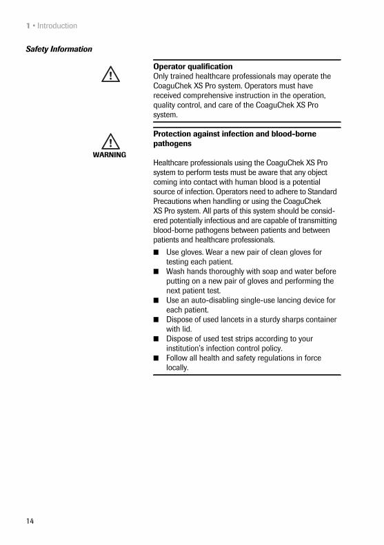
Safety Information
Operator qualification Only trained healthcare professionals may operate the CoaguChek XS Pro system. Operators must have received comprehensive instruction in the operation, quality control, and care of the CoaguChek XS Pro system.
WARNING
Protection against infection and blood-borne pathogens
Healthcare professionals using the CoaguChek XS Pro system to perform tests must be aware that any object coming into contact with human blood is a potential source of infection. Operators need to adhere to Standard Precautions when handling or using the CoaguChek XS Pro system. All parts of this system should be consid-ered potentially infectious and are capable of transmitting blood-borne pathogens between patients and between patients and healthcare professionals.
■ Use gloves. Wear a new pair of clean gloves for testing each patient.
■ Wash hands thoroughly with soap and water before putting on a new pair of gloves and performing the next patient test.
■ Use an auto-disabling single-use lancing device for each patient.
■ Dispose of used lancets in a sturdy sharps container with lid.
■ Dispose of used test strips according to your institution’s infection control policy.
■ Follow all health and safety regulations in force locally.

Introduction • 1
15
Disposal of the System
WARNING
Avoidance of electrical shock, fire, and explosions■ Only use Roche Diagnostics original accessories
(cables, power supply units, battery packs, and spare parts). Third-party cables, power supply units, and battery packs can cause the battery pack to explode or the meter to become damaged.
■ Do not use loose power sockets or damaged power supply units, cables, plugs, or battery packs.
■ Do not short circuit the power supply unit, the hand-held base unit contacts, or the battery pack.
■ Do not drop the CoaguChek XS Pro meter, the power supply unit, or the battery pack and protect these against shaking and vibrations.
WARNING
Infection by a potentially biohazardous instrumentThe CoaguChek XS Pro system or its components must be treated as potentially biohazardous waste. Decontam-ination (i.e., a combination of processes including clean-ing, disinfection and/or sterilization) is required before reuse, recycling, or disposal.
Dispose of the system or its components according to the appropriate local regulations.

1 • Introduction
16
WARNING
Possible hazards posed by the lithium-ion battery packDamaged or swollen lithium-ion (Li-ion) battery packs can overheat, catch fire, or leak. Immediately cease use of CoaguChek XS Pro meters with damaged or swollen Li-ion battery packs. Under no circumstances recharge meters with damaged or swollen Li-ion battery packs by placing them in the handheld base unit or connecting them to the power adapter.
Overheating can cause the battery pack to catch fire or explode.
■ Never throw the battery pack or the meters onto a fire. Do not dismantle, compress, or pierce the battery pack as this could cause an internal short circuit that leads to overheating.
■ Do not place either the battery pack or the CoaguChek XS Pro meter on or in heating appli-ances, such as a microwave, conventional oven, or radiator.
■ Avoid prolonged exposure to direct sunlight, e.g., when the meter is docked in the handheld base unit. Keep this in mind when positioning the handheld base unit.
Battery fluid or materials leaking from damaged battery packs can irritate your skin or cause burns due to high temperatures.
■ Avoid contact with leaking battery fluid. In the event of accidental contact with the skin, rinse with water. If you get battery fluid in your eye(s), you should also seek medical attention.
Handle and dispose of battery packs with care.
Extreme temperatures reduce the charging capacity and usage period of the meter and the battery pack.

Introduction • 1
17
General Care
Disposal of used batteriesDo not dispose of the batteries with normal domestic waste. Dispose of used batteries in an environmentally responsible manner and in accordance with applicable local regulations and directives. Contact your local council/local authority or the manufacturer of the used batteries for advice on correct disposal.
NOTICE Clean the meter only with the solutions recommended (see page 119). Using other solutions may result in incorrect operation and possible system failure. Do not let cleaning solution enter the instrument. Make sure that the meter is thoroughly dried after cleaning or disinfecting.

1 • Introduction
18
Laser Scanner The built-in barcode scanner emits a laser beam when activated.
The built-in barcode scanner is a Class 1 laser, according to EN 60825-1:2007.
Electromagnetic Interference
Touchscreen
Local Area Network: protection from unauthorized access
If this product is connected to a local area network, this network must be protected against unauthorized access. In particular, it must not be linked directly to any other network or the Internet. Customers are responsible for the security of their local area network, especially in pro-tecting it against malicious software and attacks. This protection might include measures, such as a firewall, to separate the device from uncontrolled networks as well as measures that ensure that the connected network is free of malicious code.
WARNING
A barcode does not need to be present for the laser scanner to become active. Do not stare directly into the laser beam.
Do not use the meter near strong electromagnetic fields, which could interfere with the proper operation of the meter.
NOTICE ■ Use only your finger (even when wearing gloves) or special pens designed for use with touchscreens to touch the screen elements. Using pointed or sharp-edged objects can damage the touchscreen.
■ Avoid prolonged exposure to direct sunlight. Direct sunlight may reduce the life expectancy and func-tionality of the display.

Introduction • 1
19
Wired network connection If the Handheld Base Unit from Roche is used to connect this meter to a local area network, the Handheld Base Unit must be protected against unauthorized access by means of a strong password management. Observe your own facility guidelines on password management where available, or apply the following rules:
Characteristics of strong passwords
■ Passwords must not contain the user’s account name or parts of the user’s full name that exceed two consecutive characters.
■ Passwords must be at least eight characters in length.
■ Passwords must contain characters from at least three of the following four categories:
– English uppercase alphabetic characters (A through Z)
– English lowercase alphabetic characters (a through z)
– Numeric characters (0 through 9)
– Non-alphabetic characters (for example, !, $, #, %)
Examples of weak passwords
■ uhxwze11 contains no upper case letter.
■ UHXW13SF contains no lower case letter.
■ uxxxxx7F contains the same character more than four times.
■ x12useridF contains a substring of the user ID longer than four characters.

1 • Introduction
20
Operating conditions To ensure that the meter functions properly, please observe the following guidelines:
■ Only use the meter at a room temperature between 15 °C and 32 °C (59 °F and 90 °F).
■ Only use the meter at a relative humidity between 10% and 85% (no condensation).
■ When operating the meter using the power adapter, use only a voltage of 100 V to 240 V (± 10%) , 50/60 Hz.
■ When testing, place the meter on a level, vibration-free surface, or hold it so it is roughly horizontal.
Quality control The meter has a number of built-in quality-control func-tions:
■ A check of the electronic components and func-tions every time the meter is powered on.
■ A check of the test strip temperature while a test is in progress.
■ A check of the expiration date and lot information on the test strip based on the code chip data.
■ A two-level, onboard quality control test and patient result determination within a single test chamber.
Roche Diagnostics has available optional liquid quality controls for the CoaguChek XS Pro system. These con-trols are provided to assist with meeting regulatory com-pliance requirements as applicable to your facility.

The CoaguChek XS Pro Meter • 2
21
2 The CoaguChek XS Pro Meter
AB
C
DG
I J
F
H K L
E

2 • The CoaguChek XS Pro Meter
22
2.1 Overview of the meter elements
A TouchscreenShows test results, information, icons, and results recalled from memory. To select an option, simply touch the button lightly.
B On/Off buttonPress and hold this button to power the meter on or off.
C Test strip guide coverRemove this cover to clean the test strip guide (if it has become soiled, e.g., with blood).
D Test strip guideInsert the test strip here.
E Barcode scanner (Laser)The integrated barcode scanner can read operator and patient IDs into the meter.
F Tab for battery compartment cover
G Battery compartment coverCovers the battery compartment (4 standard AA alkali-manganese batteries or the rechargeable battery pack).
H Charging terminalsUsed for power supply and/or charging the battery pack, when the meter is docked in the (optional) Handheld Base Unit.
I Code chip slotInsert the code chip here.
J Connection socket for power adapterPlug in the power adapter here.
K Infrared interface (Covered by the semi-transparent panel) Supports data communication.
L Reset buttonUse this button to reset the meter in case of software or power-up errors.

The CoaguChek XS Pro Meter • 2
23
2.2 Buttons and icons overview
The buttons and icons that appear during normal opera-tion are shown here, along with their respective mean-ings. Error messages and the description of the icons linked to them are provided in a separate chapter. See “Troubleshooting” starting on page 127.
Button/Icon MeaningGo to Main Menu
OK; save setting
Cancel; discard setting
Return (to previous menu)
Reduce/increase the value displayed.Scroll through lists that are too long to be displayed all at once.Inactive button:Value cannot be further decreased/increased or:End of list in this direction is reachedList of tests of a specific patient
Print after test result or from memory
Add a comment
Operator must wait until the meter has completed an action
Insert test strip
Remove test strip
Apply sample (the time left to apply sample is counted down in the display)
180 SEC

2 • The CoaguChek XS Pro Meter
24
Apply liquid control (QC) sample (the time left to apply sample is counted down in the display)
Insert the test strip code chip
Insert the QC code chip
Automatic quality control completed successfully
Results are displayed as a Quick percentage value
Results are displayed in seconds
Results are displayed in INR units
Result in the chosen unit of measure is above the measuring range.
Result in the chosen unit of measure is below the measuring range.
Quality control: Result is above the specified range
Quality control: Result is below the specified range
Battery status:
■ When the batteries still have their full charge, all segments are lit.■ Individual segments disappear one by one as the batteries
become weaker.■ When there is no segment remaining, you can no longer perform
a test. You can, however, still access the meter's memory.Operation with power supply adapter
Time between midnight and noon (in 12-hour time format)
Time between noon and midnight (in 12-hour time format)
Room or meter temperature is outside the acceptable range
Button/Icon Meaning
180 SEC
QC
QC%QSecINR
am
pm

The CoaguChek XS Pro Meter • 2
25
2.3 Power supply
The CoaguChek XS Pro meter can be operated with either the power adapter provided, four standard type AA alkaline, non-rechargeable batteries, or a special rechargeable battery pack (optional). Insert the batteries or the optional rechargeable battery pack even when you use the power adapter. This ensures that you will not lose the date and time settings if the power goes out.
To save power, the CoaguChek XS Pro meter has the option to automatically power itself off based on your setup selections, unless a button has been pressed or a new test strip has been inserted. The default setting is set to 5 minutes. When the meter powers itself off, all results obtained up to that point remain in memory and the set-tings will still be there when you power the meter back on. (Refer to “Auto Off” on page 50.)
The test strip guide cover is open
Communication is taking place via the infrared interface
Reports a status message (see: Chapter 10, Troubleshooting)
Reports an error message or a warning (see: Chapter 10, Troubleshooting)
Button/Icon Meaning
The power adapter also serves as a charger if you use it with the special rechargeable battery pack.
2 • The CoaguChek XS Pro Meter
26
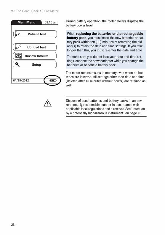
During battery operation, the meter always displays the battery power level.
The meter retains results in memory even when no bat-teries are inserted. All settings other than date and time (deleted after 10 minutes without power) are retained as well.
When replacing the batteries or the rechargeable battery pack, you must insert the new batteries or bat-tery pack within ten (10) minutes of removing the old one(s) to retain the date and time settings. If you take longer than this, you must re-enter the date and time.
To make sure you do not lose your date and time set-tings, connect the power adapter while you change the batteries or handheld battery pack.
Main Menu 09:15 am
04/19/2012
Control Test
Review Results
Setup
Patient Test
Dispose of used batteries and battery packs in an envi-ronmentally responsible manner in accordance with applicable local regulations and directives. See “Infection by a potentially biohazardous instrument” on page 15.

Putting the Meter into Operation • 3
27
3 Putting the Meter into Operation
Before using the meter for the first time, perform the fol-lowing steps:
1 Insert batteries and/or connect the power adapter
2 Set the current date and time
3 Enter the settings of choice (language, unit of measure, user administration if applicable, etc.)
Instead of batteries, you can use a special rechargeable battery pack. If you choose this option, order the pack separately from Roche Diagnostics. To recharge, con-nect the power adapter to the CoaguChek XS Pro meter or to the optional Handheld Base Unit (HBU) and dock the meter.
The meter’s battery power level indicator is designed for use with either standard, non-rechargeable AA batter-ies or the dedicated Roche handheld battery pack. We do not recommend the use of off-the-shelf rechargea-ble batteries in AA format. These have lower voltages than standard AA batteries or the special Roche hand-held battery pack. This can lead to incorrect battery power level indications on the meter.

3 • Putting the Meter into Operation
28
3.1 Inserting the batteries
1 With the meter powered off, press the battery com-partment cover release tab and slide the cover off.
2 Insert the four batteries in the battery compartment as indicated.
The batteries should last about 80 tests, depending on the type of battery used.

Putting the Meter into Operation • 3
29
3 Slide the battery compartment back onto the meter and close it.
The meter powers itself on after the batteries have been inserted.
3.2 Powering the meter on and off
1 Place the meter on a level, vibration-free surface, or hold it in your hand so it is roughly horizontal.
2 Power the meter on by pressing the button for approximately 1 second.
3 To power the meter off after use, press the button for approximately 1 second.
You can also power on the meter directly by inserting a test strip or connecting the power adapter.

3 • Putting the Meter into Operation
30
Checking the software version
After displaying the Roche logo, the meter briefly displays the Init (for “initialization”) screen. Here you can check which software version is currently running on your meter. (The Init screen shown here is for illustration pur-poses only. Version numbers on your meter may differ.)
Init
CoaguChekXS Pro
03.01.03

Meter Setup • 4
31
4 Meter Setup
Note on presentation of screen elements in this manual
Buttons are screen prompts that cause something to happen when touched. The names of all buttons are either shown as bold text or as the icon used on the button (e.g., for OK).
Other screen elements (e.g., Menu titles) are written in italics. These screen elements are not active.
You can open any displayed function by touching (or tap-ping) the button for it with your finger (or a special pen for this purpose). “Tap” means: Touch the button, then remove your finger from the touchscreen. The next screen appears once you remove your finger.
If the meter did not automatically enter the Setup mode (e.g., after the batteries were replaced), you can open the Setup menu from the Main Menu.
If you have not set the date and time (after powering on for the first time or because the batteries were removed from the meter for more than 10 minutes), you cannot perform a test. In that case powering on the meter takes you immediately to the Setup mode, where you must set the date and time (see page 41 and following).
After date and time have been set, the meter automati-cally moves to the Main Menu, where you can start a test or enter more settings.

4 • Meter Setup
32
1 Touch Setup to open the meter settings.
2 Select the group of settings of choice (see the Settings summary following this section.).
Main Menu 09:15 am
04/19/2012
Control Test
Review Results
Setup
Patient Test
Setup Menu 09:15 am
04/19/2012
ID Setup
QC Settings
Options
Screen

Meter Setup • 4
33
4.1 Settings summary
The diagram below shows all of the setup areas that can be accessed on the meter.
Setup
Screen
Options
ID Setup
QC Settings
Result Units
QC Lockout
Beeper
Operator
Contrast
QC Range
Sort
Admin.
Language Selection
Result Confirmation
Operator Lockout
Auto Off
Date / Time
STAT Test Config.
Connection
Patient

4 • Meter Setup
34
* Default settings are labeled with an asterisk (*).
Group Subgroup Setting Values *
Screen Contrast 0 – 10 (5 *)
Result Units INR *INR/SECINR/%Q
Result Confirmation EnableDisable *
Language Selection DanskDeutschEnglish *EspañolFrançaisItalianoNederlandsNorskPortuguêsSuomiSvenska
Date/Time Date 01/01/2012 *Time 12:00 am *Date formats DD.MM.YYYY (01.01.2012)
MM/DD/YYYY (01/01/2012) *YYYY-MM-DD (2012-01-01)
Time formats 24-hour time format (24h)12-hour time format (12h), with am/pm *

Meter Setup • 4
35
* Default settings are labeled with an asterisk (*).
Group Subgroup Setting Values *
Options Sort Date/Time *
Patient ID Patient Name
Beeper Beeper OffLowMedium *High
Key Click Off *On
Auto Off [minutes] Off1 … (5*) … 10 15202530405060
Connection Off *ComputerPrinter

4 • Meter Setup
36
* Default settings are labeled with an asterisk (*).
Group Subgroup Setting Values *
ID Setup Admin. (Administrator) Blank (Off) *
Operator (Operator List is optional) ActiveInactive *
Patient No *OptionalRequired
QC Settings QC Range Default Range*
Custom Range Display Target Value On/Off *Deviation from Target ValuePercentage (%)
Operator Lockout (only if the Operator option is set to Active and an operator list is available)
Off *WeeklyMonthlyEvery 3 monthsEvery 6 monthsYearly
QC Lockout New code YesNo *
General No *DailyWeeklyMonthly
STAT Test Config. EnableDisable *Quantity

Meter Setup • 4
37
4.2 Screen setup
The Screen setup area contains the options for changing the display.
Contrast Use the Contrast menu to adjust the display to your ambi-ent light conditions and make it easier to read.
1 From the Main Menu, touch Setup to open the meter settings.
2 From the Setup Menu, touch Screen.
3 From the Screen menu, touch Contrast.
4 Touch or to change the contrast in a range from 0 to 10.
■ Contrast “0” makes the display very dark.
■ Contrast “10” makes the display very light.
5 Touch to save this setting, or touch to exit this menu without saving any changes. The display automatically returns to the previous screen.
Main Menu 09:15 am
04/19/2012
Control Test
Review Results
Setup
Patient Test
Setup Menu 09:15 am
04/19/2012
ID Setup
QC Settings
Options
Screen
Screen 09:15 am
04/19/2012
Language Selection
Date / Time
Result Units
Contrast
Result Confirmation
If a button is grayed out, this means the function is not available.
Contrast 09:15 am
04/19/2012
Contrast (0-10):
5

4 • Meter Setup
38
Result Units Use this setting to select the unit(s) of measure to be dis-played with the results.
1 From the Main Menu, touch Setup to open the meter settings.
2 From the Setup Menu, touch Screen.
3 From the Screen menu, touch Result Units.
The current unit of measure setting is highlighted (white type on a blue background). You can select either:
■ INR
■ INR and seconds
■ INR and Quick value in %
4 Touch the button to select the unit of measure of choice. Your selection is now highlighted.
5 Touch to save this setting, or touch to exit this menu without saving any changes. The display automatically returns to the previous screen.
Main Menu 09:15 am
04/19/2012
Control Test
Review Results
Setup
Patient Test
Setup Menu 09:15 am
04/19/2012
ID Setup
QC Settings
Options
Screen
Screen 09:15 am
04/19/2012
Language Selection
Result Confirmation
Date / Time
Result Units
Contrast
Units 09:15 am
04/19/2012
INR
INR/SEC
INR/%Q

Meter Setup • 4
39
Result Confirmation In some circumstances, it may be useful for operators to confirm the validity of their results. Use this setting to prompt operators to confirm the results of every test.
1 From the Main Menu, touch Setup to open the meter settings.
2 From the Setup Menu, touch Screen.
3 From the Screen menu, touch Result Confirma-tion.
4 Touch Enable or Disable. Your selection is now highlighted.
5 Touch to save this setting, or touch to exit this menu without saving any changes. The display automatically returns to the previous screen.
Main Menu 09:15 am
04/19/2012
Control Test
Review Results
Setup
Patient Test
Setup Menu 09:15 am
04/19/2012
ID Setup
QC Settings
Options
Screen
Screen 09:15 am
04/19/2012
Language Selection
Result Confirmation
Date / Time
Result Units
Contrast
Units 09:15 am
04/19/2012
INR
INR/SEC
INR/%Q

4 • Meter Setup
40
Language Selection Use this setting to select the language for all displays (that contain text).
1 From the Main Menu, touch Setup to open the meter settings.
2 From the Setup Menu, touch Screen.
3 From the Screen menu, touch Language Selec-tion.
The current language setting is highlighted (white type on a blue background). You can select either:
■ Dansk
■ Deutsch
■ English
■ Español
■ Français
■ Italiano
■ Nederlands
■ Norsk
■ Português
■ Suomi
■ Svenska
Main Menu 09:15 am
04/19/2012
Control Test
Review Results
Setup
Patient Test
Setup Menu 09:15 am
04/19/2012
ID Setup
QC Settings
Options
Screen
Screen 09:15 am
04/19/2012
Language Selection
Result Confirmation
Date / Time
Result Units
Contrast

Meter Setup • 4
41
4 Touch or to display the language of choice on the screen.
If the arrow is just an outline , you have reached the end of the list in the repective direction.
5 Touch the button to select the language of choice. Your selection is now highlighted.
6 Touch to save this setting, or touch to exit this menu without saving any changes. The display automatically returns to the previous screen.
Setting the date When you power on the meter for the first time (or after a long period without power), the input field for the date automatically appears first. The date (and time) must be entered before the meter can be used further. If at a later time a date adjustment is needed, go to the Setup menu, then select the menu of choice.
Language 09:15 am
04/19/2012
Deutsch
English
Español
Dansk
Français
Both Date and Time display formats are controlled by the Format options you select (see page 44). Options shown in the Date and Time menus may vary depending on the chosen formats. You can choose between the following display formats:
■ Date: Day.Month.Year, e.g., 01.01.2012 ■ Date: Month/Day/Year, e.g., 01/01/2012 ■ Date: Year-Month-Day, e.g., 2012-01-01 ■ Time: 24H or 12H

4 • Meter Setup
42
1 From the Main Menu, touch Setup to open the meter settings.
2 From the Setup Menu, touch Screen.
3 From the Screen menu, touch Date/Time.
4 From the Date/Time menu, touch Set Date.
5 Touch and to set the year, then the month, then the day.
6 Touch to save this setting, or touch to exit this menu without saving any changes. The display automatically returns to the previous screen.
If this setup menu appeared automatically after powering the meter on, you must touch to complete the first date setting.
7 Touch to return to the Screen menu.
Main Menu 09:15 am
04/19/2012
Control Test
Review Results
Setup
Patient Test
Setup Menu 09:15 am
04/19/2012
ID Setup
QC Settings
Options
Screen
Screen 09:15 am
04/19/2012
Language Selection
Result Confirmation
Date / Time
Result Units
Contrast
Date/Time 09:15 am
04/19/2012
Format
Set Time
Set Date
Date 09:15 am
04/19/2012
Month: 1
Day: 1
Year: 2012

Meter Setup • 4
43
Setting the time When you power on the meter for the first time (or after a long period without power), this Setup menu appears automatically after you set the date. If at a later time a time adjustment is needed, go to the Setup menu, then select the menu of choice.
1 From the Main Menu, touch Setup to open the meter settings.
2 From the Setup Menu, touch Screen.
3 From the Screen menu, touch Date/Time.
4 From the Date/Time menu, touch Set Time.
5 Touch and to set the hours, then the min-utes.
6 Touch to save this setting, or touch to exit this menu without saving any changes. The display automatically returns to the previous screen.
If this setup menu appeared automatically after powering the meter on, you must touch to complete the first time setting.
7 Touch to return to the Screen menu.
Main Menu 09:15 am
04/19/2012
Control Test
Review Results
Setup
Patient Test
Setup Menu 09:15 am
04/19/2012
ID Setup
QC Settings
Options
Screen
Screen 09:15 am
04/19/2012
Language Selection
Result Confirmation
Date / Time
Result Units
Contrast
Date/Time 09:15 am
04/19/2012
Format
Set Time
Set Date
Time 09:15 am
04/19/2012
Minute: 59
Hour: 9
AM PM

4 • Meter Setup
44
Setting the display options for date and time
Select your preferred format for the date and time display.
1 From the Main Menu, touch Setup to open the meter settings.
2 From the Setup Menu, touch Screen.
3 From the Screen menu, touch Date/Time.
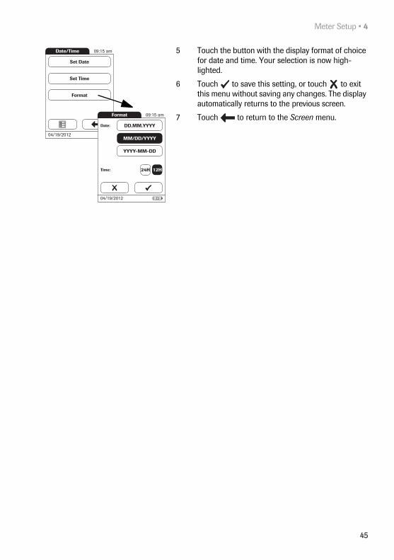
4 From the Date/Time menu screen, touch Format.
The current settings are highlighted. You can select one of the following display formats:
■ Date: DD.MM.YYYY (Day.Month.Year), e.g., 30.09.2012
■ Date: MM/DD/YYYY (Month/Day/Year), e.g., 09/30/2012
■ Date: YYYY-MM-DD (Year-Month-Day), e.g., 2012-09-30
■ Time: 24H or 12H
Main Menu 09:15 am
04/19/2012
Control Test
Review Results
Setup
Patient Test
Setup Menu 09:15 am
04/19/2012
ID Setup
QC Settings
Options
Screen
Screen 09:15 am
04/19/2012
Language Selection
Result Confirmation
Date / Time
Result Units
Contrast
Meter Setup • 4
45
5 Touch the button with the display format of choice for date and time. Your selection is now high-lighted.
6 Touch to save this setting, or touch to exit this menu without saving any changes. The display automatically returns to the previous screen.
7 Touch to return to the Screen menu.
Date/Time 09:15 am
04/19/2012
Format
Set Time
Set Date
Format 09:15 am
04/19/2012
Date: DD.MM.YYYY
MM/DD/YYYY
YYYY-MM-DD
Time: 24H 12H

4 • Meter Setup
46
4.3 Options setup
Sort Sort refers to the order in which measured and stored results are displayed when you use the Review Results function of the CoaguChek XS Pro meter. You can display stored results chronologically by date and time or by per-son, based on the Patient ID. If you are working with a DMS and a patient list, you can also display the patient list and the stored results sorted by Patient Name.
1 From the Main Menu, touch Setup to open the meter settings.
2 From the Setup Menu, touch Options.
3 From the Options menu, touch Sort.
Options 09:15 am
04/19/2012
Auto Off
Connection
Beeper
Sort
Main Menu 09:15 am
04/19/2012
Control Test
Review Results
Setup
Patient Test
Setup Menu 09:15 am
04/19/2012
ID Setup
QC Settings
Options
Screen

Meter Setup • 4
47
The current setting is highlighted. You may select from the following sort options:
■ By Date/Time
■ By Patient ID
■ By Patient Name
4 Touch the button to select the Sort by option of choice. Your selection is now highlighted.
5 Touch to save this setting, or touch to exit this menu without saving any changes. The display automatically returns to the previous screen.
The sort option Patient Name is available only when used together with a patient list. Patient lists can only be created with a DMS. For more details see “Data han-dling”, starting on page 111.
Sort 09:15 am
04/19/2012
Date / Time
Patient ID
Sort By:
Patient Name

4 • Meter Setup
48
Beeper The CoaguChek XS Pro meter can display information visually and alert you to special circumstances with a Beeper. When the Beeper is enabled, the meter beeps when:
■ it is switched on
■ it detects a test strip
■ pre-heating of the test strip is complete and you need to apply a sample
■ it detects a sample
■ the test is completed and the results are displayed (a long beep)
■ an error occurs (three short beeps)
■ an external power adapter is connected when the meter is on
■ a barcode is scanned
You can also activate a Key Click. When a Key Click is enabled, the meter clicks briefly every time a button is touched, facilitating the input of information.
We recommend that you keep the Beeper enabled at all times.

Meter Setup • 4
49
1 From the Main Menu, touch Setup to open the meter settings..
2 From the Setup Menu, touch Options.
3 From the Options menu, touch Beeper.
The current setting is highlighted. You may select from the following options:
For the Beeper
■ Off
■ Low
■ Medium
■ High
For the Key Click
■ On
■ Off
4 Touch the button with the desired setting for the Beeper, then touch the button with the setting of choice for the Key Click. Both selections are now highlighted.
5 Touch to save this setting, or touch to exit this menu without saving any changes. The display automatically returns to the previous screen.
Options 09:15 am
04/19/2012
Auto Off
Connection
Beeper
Sort
Main Menu 09:15 am
04/19/2012
Control Test
Review Results
Setup
Patient Test
Setup Menu 09:15 am
04/19/2012
ID Setup
QC Settings
Options
Screen
Beeper 09:15 am
04/19/2012
Key Click:On Off
Low
Medium
High
Off

4 • Meter Setup
50
Auto Off You can set up your CoaguChek XS Pro meter so that it powers itself off automatically if it has not been used (no buttons touched or tests run) for a preselected time period. Use this feature to save power and extend the life of the batteries.
1 From the Main Menu, touch Setup to open the meter settings.
2 From the Setup Menu, touch Options.
3 From the Options menu, touch Auto Off.
Options 09:15 am
04/19/2012
Auto Off
Connection
Beeper
Sort
Main Menu 09:15 am
04/19/2012
Control Test
Review Results
Setup
Patient Test
Setup Menu 09:15 am
04/19/2012
ID Setup
QC Settings
Options
Screen
If the meter is connected to the power adapter or the Handheld Base Unit, the Auto Off function has a differ-ent effect:
■ If you work with operator IDs, the meter switches to Operator Login, once Auto Off is triggered.
■ If you do not work with operator IDs, the meter switches to the Main Menu, once Auto Off is triggered.
For information on Operator ID, see “Operator ID” on page 60.

Meter Setup • 4
51
You may select from the following options:
■ Off (meter never powers itself off)
■ Time until meter powers itself off:1…10, 15, 20, 25, 30, 40, 50, 60 minutes
4 Touch or to select the time of choice in minutes or to switch the feature off.
5 Touch to save this setting, or touch to exit this menu without saving any changes. The display automatically returns to the previous screen.
Connection In the Connection menu you can configure the data exchange with external devices. The meter can be con-nected either to a computer or a printer.
1 From the Main Menu, touch Setup to open the meter settings.
2 From the Setup Menu, touch Options.
3 From the Options menu, touch Connection.
Auto Off 09:15 am
04/19/2012
5
Minutes:
Options 09:15 am
04/19/2012
Auto Off
Connection
Beeper
Sort
Main Menu 09:15 am
04/19/2012
Control Test
Review Results
Setup
Patient Test
Setup Menu 09:15 am
04/19/2012
ID Setup
QC Settings
Options
Screen
4 • Meter Setup
52
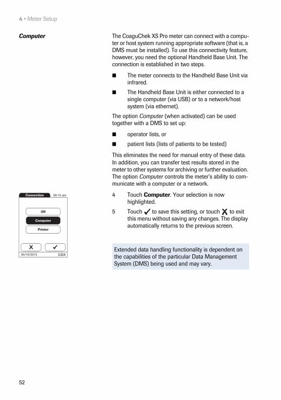
Computer The CoaguChek XS Pro meter can connect with a compu-ter or host system running appropriate software (that is, a DMS must be installed). To use this connectivity feature, however, you need the optional Handheld Base Unit. The connection is established in two steps.
■ The meter connects to the Handheld Base Unit via infrared.
■ The Handheld Base Unit is either connected to a single computer (via USB) or to a network/host system (via ethernet).
The option Computer (when activated) can be used together with a DMS to set up:
■ operator lists, or
■ patient lists (lists of patients to be tested)
This eliminates the need for manual entry of these data. In addition, you can transfer test results stored in the meter to other systems for archiving or further evaluation. The option Computer controls the meter’s ability to com-municate with a computer or a network.
4 Touch Computer. Your selection is now highlighted.
5 Touch to save this setting, or touch to exit this menu without saving any changes. The display automatically returns to the previous screen.
Extended data handling functionality is dependent on the capabilities of the particular Data Management System (DMS) being used and may vary.
Connection 09:15 am
04/19/2012
Printer
Computer
Off

Meter Setup • 4
53
Printer The CoaguChek XS Pro meter can also connect directly to a printer. To use the printing feature you need an optional infrared printer.
1 From the Main Menu, touch Setup to open the meter settings.
2 From the Setup Menu, touch Options.
3 From the Options menu, touch Connection.
4 Touch Printer. Your selection is now highlighted.
5 Touch to save this setting, or touch to exit this menu without saving any changes. The display automatically returns to the previous screen.
To print :
■ Align the meter with the IR printer.
■ At any test or memory screen, touch .
Options 09:15 am
04/19/2012
Auto Off
Connection
Beeper
Sort
Main Menu 09:15 am
04/19/2012
Control Test
Review Results
Setup
Patient Test
Setup Menu 09:15 am
04/19/2012
ID Setup
QC Settings
Options
Screen
The printer icon only appears if the printer function is activated. Otherwise it is not displayed.
If you work with the meter in a language other than English: With the exception of information you have entered - such as patient ID and name, operator ID, comments - the printout will be in English. (See “Lan-guage Selection” on page 40.)
Connection 09:15 am
04/19/2012
Printer
Computer
Off
Memory 09:15 am
04/19/2012
P-ID: PID01
Code: 184
2.5INR
Smith, HenryOp: Operator 1Par: PT
Doctor NotifiedSick
Travel
21%Q
04/18/2012 11:31 am

4 • Meter Setup
54
4.4 ID setup
Use the ID Setup menu to enter settings for user man-agement and patient management. These settings are optional and set to Off/Inactive by default; the meter can be operated without these settings.
There are three types of identification used with the meter:
■ System Administrator: The Admin. (Administra-tor) has special rights to enter certain meter set-tings and is the only one who can enter and change these settings. It is not necessary for Admin. identi-fication to be activated to use the CoaguChek XS Pro meter. However, it might be desired or neces-sary, depending on the regulatory environment and the site of use.
■ Operator: The Operator ID is assigned to persons who use the meter to run tests. If you want to use Operator IDs, you have several options:
– You may use Operator IDs to restrict the use of the meter to qualified personnel or a predefined group of users. In this case an operator list created exter-nally must be transferred to the meter, enabling you to select an Operator ID when logging in. For more details see “Data handling”, starting on page 111.
– You may use Operator IDs for informational pur-poses only, in order to assign stored measurement results to the users who performed the test. In this case Operator IDs may be entered directly on the meter (by keypad or scanner), with or without an operator list being available.

Meter Setup • 4
55
■ Patient: The Patient ID is assigned to the person, whose test results are recorded. You can either:
– block input of a unique Patient ID (in this case, every test is simply numbered in consecutive order)
– allow a unique Patient ID as optional, or
– require a unique Patient ID for every test. Patient lists created externally can also be transferred to the meter, enabling you to select Patient IDs for a test from these lists. For more details see “Data handling”, starting on page 111.
Operator IDs can be selected from a list (if available) or read by the barcode scanner on the side of the meter. If passwords were created, they must be entered via the onscreen keypad. Patient IDs can be entered by using the onscreen keypad or the barcode scanner on the side of the meter. For more information on working with operator and patient ID barcodes, see “Data handling”, starting on page 111.
The buttons in the ID Setup menu show what the current settings are (this is just an example, the screen may look different on your meter):
■ The standard display of the Admin. button means the function is available but not activated (a pass-word for the system administrator/supervisor has not been assigned).
■ The standard display of the Operator button means the Operator login is available but not acti-vated.
■ When the Patient button is highlighted (that is, when it has a blue background) this means the function is available and activated (either as Optional or Required).
ID Setup 09:15 am
04/19/2012
Patient
Operator
Admin.

4 • Meter Setup
56
System Administrator (Admin.) In the default setting, the meter is not protected with an Admin. password, and all setup options are accessible to every user. If you set up an Admin. password, the follow-ing setup areas are automatically reserved only for the system administrator/supervisor (i.e., the person who knows the password).
■ Screen: Result Units, Date/Time
■ Options: Connection (to a computer or a printer)
■ ID Setup (the entire area)
■ QC Lockout
■ QC Range
■ Operator Lockout (only available in combination with a data management system)
If an Admin. password has not been set up yet:
1 From the Main Menu, touch Setup to open the meter settings.
2 From the Setup Menu, touch ID Setup.
3 From the ID Setup menu , touch Admin.
When you enter an Admin. password, this password will have to be entered from this point forward before any of the settings above can be changed. The Admin. pass-word must also be entered before you can delete or change the Admin. password itself. If you forget the Admin. password, contact your Roche representative.
ID Setup 09:15 am
04/19/2012
Patient
Operator
Admin.
Main Menu 09:15 am
04/19/2012
Control Test
Review Results
Setup
Patient Test
Setup Menu 09:15 am
04/19/2012
ID Setup
QC Settings
Options
Screen

Meter Setup • 4
57
4 Using the keypad displayed on the screen, enter the Admin. password of choice. The password can con-sist of up to 20 characters.
5 Use to switch to input of numbers.
6 Use to switch back to input of text.
7 Use to backspace and correct a mistake.
8 Touch to save this setting, or touch to exit this menu without saving any changes. The display automatically returns to the previous screen.
9 Enter the Admin. password again (the keypad is automatically displayed again on the screen) to confirm the first entry.
10 Touch to save this entry, (the Admin. password is now set), or touch to exit this menu, the Admin. password is not set and is therefore still inactive.
The display automatically returns to the ID Setup menu. After you exit the Setup menu, only an authenticated administrator may further edit the setup areas as listed before (see page 56).
Pay close attention to the buttons you press, because the characters are not displayed on the screen. Aster-isks are displayed instead (as if entering a password on a computer).
Admin.
A
***|B C D E
F G H I J
K L M N O
P Q R S T
U V W X Y
Z 123
09:15 am
Admin.
0
|1 2 3 4
5 6 7 8 9
ABC
09:15 am
Repeat ID
A
***|B C D E
F G H I J
K L M N O
P Q R S T
U V W X Y
Z 123
09:15 am
123
ABC

4 • Meter Setup
58
Changing an existing Admin. password:
1 From the Main Menu, touch Setup to open the meter settings.
2 From the Setup Menu, touch ID Setup.
3 Using the keypad displayed on the screen, enter the valid Admin. password.
The ID Setup menu is displayed. The Admin. button is highlighted, which means an Admin. password is active.
4 Touch Admin.
5 Using the keypad displayed on the screen, enter (and confirm) the new Admin. password of choice.
Admin.
A
***|B C D E
F G H I J
K L M N O
P Q R S T
U V W X Y
Z 123
09:15 amID Setup 09:15 am
04/19/2012
Patient
Operator
Admin.
Main Menu 09:15 am
04/19/2012
Control Test
Review Results
Setup
Patient Test
Setup Menu 09:15 am
04/19/2012
ID Setup
QC Settings
Options
Screen

Meter Setup • 4
59
Deactivating an existing Admin. password:
1 From the Main Menu, touch Setup to open the meter settings.
2 From the Setup Menu, touch ID Setup.
3 Using the keypad displayed on the screen, enter the valid Admin. password.
The ID Setup menu is displayed. The Admin. button is highlighted, which means an Admin. password is active.
4 Touch Admin.
5 Immediately touch to close the keypad on the screen without entering a password.
The Admin. password has been deleted and therefore deactivated. The Admin. button is no longer highlighted.
Admin.
A
***|B C D E
F G H I J
K L M N O
P Q R S T
U V W X Y
Z 123
09:15 amID Setup 09:15 am
04/19/2012
Patient
Operator
Admin.
Main Menu 09:15 am
04/19/2012
Control Test
Review Results
Setup
Patient Test
Setup Menu 09:15 am
04/19/2012
ID Setup
QC Settings
Options
Screen
ID Setup 09:15 am
04/19/2012
Patient
Operator
Admin.
Admin.
A
|B C D E
F G H I J
K L M N O
P Q R S T
U V W X Y
Z 123
09:15 am

4 • Meter Setup
60
Operator ID
In the default setting, the Operator login is not activated. You can either activate or deactivate Operator login on the meter. If activated, an Operator has to log in before the Main Menu will be displayed and measurements can be performed.
To activate Operator login:
1 From the Main Menu, touch Setup to open the meter settings.
2 From the Setup Menu, touch ID Setup.
3 From the ID Setup menu, touch Operator.
4 Touch the button with the setting of choice for set-ting up the Operator login. Your selection is now highlighted.
5 Touch to save this setting, or touch to exit this menu without saving any changes. The display automatically returns to the previous screen.
If you want to create a list of Operator IDs from which you can select an operator, additional software (a data management system) and the Handheld Base Unit are required (for more details see “Data handling”, starting on page 111).
ID Setup 09:15 am
04/19/2012
Patient
Operator
Admin.
Main Menu 09:15 am
04/19/2012
Control Test
Review Results
Setup
Patient Test
Setup Menu 09:15 am
04/19/2012
ID Setup
QC Settings
Options
Screen
Operator ID 09:15 am
04/19/2012
Inactive
Active

Meter Setup • 4
61
Patient ID
In the default setting, input of Patient IDs is set to No. This means each test is simply assigned a consecutive number. However, you can require that a Patient ID be entered or make it optional.
1 From the Main Menu, touch Setup to open the meter settings.
2 From the Setup Menu, touch ID Setup.
3 From the ID Setup menu, touch Patient.
You may select from the following options:
■ No (tests will be assigned numbers automatically)
■ Optional (automatic numbering or list/scan/manual input)
■ Required (list/scan/manual input)
4 Touch the button with the setting of choice. Your selection is now highlighted.
5 Touch to save this setting, or touch to exit this menu without saving any changes.
The settings for the option No are now completed. For the options Optional and Required, continue by selecting the input format.
If you want to create a list of Patient IDs from which you can select a patient for testing, additional software (a data management system) and the Handheld Base Unit are required (see page 111).
ID Setup 09:15 am
04/19/2012
Patient
Operator
Admin.
Main Menu 09:15 am
04/19/2012
Control Test
Review Results
Setup
Patient Test
Setup Menu 09:15 am
04/19/2012
ID Setup
QC Settings
Options
Screen
Patient ID 09:15 am
04/19/2012
No
Optional
Required

4 • Meter Setup
62
6 Select the form for input of the Patient ID.
You may select from the following options:
■ Alphanumeric Enter any combination of letters and numbers, e.g., “J. DOE 3378”
■ Numeric Enter numbers only, e.g., “3387”
■ Min. Length Enter the minimum number of characters (1 … 20) the Patient ID must have.
■ Max. Length Enter the maximum number of characters (1 … 20) the Patient ID can have.
7 Touch the button with the format of choice for the Patient ID. Your selection is now highlighted.
8 Touch or to set the number of characters (length) of choice.
9 Touch to save this setting, or touch to exit this menu without saving any changes. The display automatically returns to the previous screen.
Patient ID 09:15 am
04/19/2012
Max. Length:
Numeric
Alphanumeric
20
Min. Length:
1

Meter Setup • 4
63
4.5 QC Settings setup
The QC Settings menu contains options for enforcing the performance of liquid quality controls by the operator at specified intervals. It also provides the option of custom-izing the QC Range in accordance with applicable local guidelines.
QC Range
There are two options:■ Default Range: The meter displays the QC Range
provided by Roche in the code chip.
■ Custom Range: The option Custom Range lets the user define their own QC Range within the default range.
Lockouts (QC Lockout and Operator Lockout)
If the liquid quality control test is not performed correctly, or if the result is outside the target value range, the meter is locked from further use. The Lockout can also be set up selectively for individual operators.
A liquid quality control test must be completed success-fully before the meter is available again for testing (either by the operator or in general).
The option of setting up an Operator Lockout is availa-ble only when operator lists are created on a data man-agement system (DMS), stored in the meter, and Operator login is activated. These lists are only available in connection with a data management system. For more details see “Data handling”, starting on page 111.

4 • Meter Setup
64
QC Range Liquid Quality control ranges can be customized to comply with local guidelines. The QC Range function enables you to narrow the default range.
1 From the Main Menu, touch Setup to open the meter settings.
2 From the Setup Menu, touch QC Settings.
3 From the QC Settings menu, touch QC Range.
You may select from the following options:
■ Default Range (Range provided in the code chip is selected and displayed. No target value is dis-played.)
■ Custom Range (The allowed percentage deviation from target value can now be customized. Addi-tionally, you can choose between displaying the target value along with a control test result or not displaying the target value with the control test result.)
4 Touch the button with the setting of choice. Your selection is now highlighted.
■ If you selected Default Range, touch to save this setting, or touch to exit this menu without saving any changes.
■ If you selected Custom Range, touch to pro-ceed with corresponding settings, or touch to exit this menu without saving any changes. The dis-play automatically returns to the previous screen.
QC Settings 09:15 am
04/19/2012
QC Lockout
Operator Lockout
STAT Test Config.
QC Range
Main Menu 09:15 am
04/19/2012
Control Test
Review Results
Setup
Patient Test
Setup Menu 09:15 am
04/19/2012
ID Setup
QC Settings
Options
Screen
QC Range 09:15 am
04/19/2012
Custom Range
Default Range

Meter Setup • 4
65
If you selected Custom Range, the QC Range screen opens and offers you the following options:
■ Display target value (On/Off)
■ Deviation from target value (percentage value). See page 64.
For the control solutions, the target value always comes from the information stored in the code chip. If you have chosen Custom Range, you can now select an allowed deviation from target value in the range of 0 to 22.5% (in the illustration, 11.5%).
Note: Percentage deviation from target value is always defined using INR values. Even if you have activated % Quick in the setup, the meter always calculates the deviation using INR values; this range is then converted to % Quick in a second step. As there is no linear correlation between values expressed as INR and values expressed as % Quick, if you calculate the per-centage deviation (11.5 % in the example) using the % Quick target value, your result may deviate from the result calculated by the meter using the INR target value.
QC Range 09:15 am
04/19/2012
Custom Range
Default Range
QC Range 09:15 am
04/19/2012
Deviation from target value
Display target value On Off
11.5 %

4 • Meter Setup
66
5 Touch On (the target value will be displayed with a test result) or Off (the target value will not be dis-played). Your selection is now highlighted.
6 Use the arrows to to set the allowed percentage deviation from the target value.
Use the arrows on the left to adjust the whole number before the decimal point. Use the arrows on the right to adjust the number after the decimal point.
7 Touch to save this setting, or touch to exit this menu without saving any changes. The display automatically returns to the QC Settings screen.
The Custom Range and Target Value (if set to On) appear in a line below the control test result in the QC test and QC memory screens.
In the left hand screen, Display target value is set to Off: the custom range only is displayed below the control test result.
In the right hand screen, Display target value is set to On: both the custom range and the target value are displayed. The target value (here: 2.9) appears in front of the custom range.
QC Range 09:15 am
04/19/2012
Deviation from target value
Display target value On Off
11.5 %
QC Test 09:15 am
04/19/2012
3.0 INR04/19/2012 09:15 am
QC: 999Code: 184Op: Operator 1
Par: PTLevel: 2
(2.6 - 3.2 INR)16 %Q
(16 - 20 %Q)
QC Test 09:15 am
04/19/2012
3.0 INR04/19/2012 09:15 am
QC: 999Code: 184Op: Operator 1
Par: PTLevel: 2
(2.9, 2.6 - 3.2 INR)16 %Q
(17, 16 - 20 %Q)

Meter Setup • 4
67
QC (quality control) Lockout The QC Lockout ensures that the optional quality control tests are run on a regular basis. This is independent of the operator, however. This option should be used if you work without operator lists. It is also possible to mandate Operator Lockouts and QC Lockouts in parallel. In addition to defining time intervals, QC Lockout can also be used to specify that a quality control test must be car-ried out when a new test strip lot is used (New Code).
1 From the Main Menu, touch Setup to open the meter settings.
2 From the Setup Menu, touch QC Settings.
3 From the QC Settings menu, touch QC Lockout.
QC Settings 09:15 am
04/19/2012
QC Lockout
Operator Lockout
STAT Test Config.
QC Range
Main Menu 09:15 am
04/19/2012
Control Test
Review Results
Setup
Patient Test
Setup Menu 09:15 am
04/19/2012
ID Setup
QC Settings
Options
Screen

4 • Meter Setup
68
4 Select the triggers, based on lot and/or time, for requiring a quality control test.
You may select from the following options:
■ New Code Yes/No (applies every time a new test strip lot is used)
The general intervals are:
■ No
■ Daily
■ Weekly
■ Monthly
5 Touch the button with the option of choice when changing the test strip lot.
6 Touch the button to select the interval of choice. Your selection is now highlighted.
7 Touch to save this setting, or touch to exit this menu without saving any changes.
8 For every option except for No, you must now indi-cate the number of levels in which the quality con-trol must be performed.
9 Touch to save this setting, or touch to exit this menu without saving any changes. The display automatically returns to the previous screen.
QC Lockout 09:15 am
04/19/2012
New CodeYes No
Daily
Weekly
Monthly
No
QC Lockout 09:15 am
04/19/2012
One Level
Two Levels
Number of Levels

Meter Setup • 4
69
Operator Lockout Optional liquid quality controls can be used to ensure that an operator is performing tests properly on the CoaguChek XS Pro meter.
The Operator Lockout function constrains an operator, who has been set up in the list, to perform these quality controls on a regular basis.
1 From the Main Menu, touch Setup to open the meter settings.
2 From the Setup Menu, touch QC Settings.
3 From the QC Settings menu, touch Operator Lockout. If this button is disabled (grayed out), either no operators have been set up or the Operator ID option has been deactivated.
QC Settings 09:15 am
04/19/2012
QC Lockout
Operator Lockout
STAT Test Config.
QC Range
Main Menu 09:15 am
04/19/2012
Control Test
Review Results
Setup
Patient Test
Setup Menu 09:15 am
04/19/2012
ID Setup
QC Settings
Options
Screen
The option of setting up an Operator Lockout is availa-ble only when operator lists are created on the DMS. For more details see “Data handling”, starting on page 111. If you are not working with a DMS, only the QC Lockout is available (see “QC (quality control) Lock-out” on page 67).

4 • Meter Setup
70
4 Select the interval of choice in which the mandatory quality control tests must be performed.
You may select from the following options:
■ No (deactivated)
■ Weekly
■ Monthly
■ Every 3 Months or Every 6 Months
■ Yearly
5 Touch and to display the option of choice on the screen.
6 Touch the button to select the interval of choice. Your selection is now highlighted.
7 Touch to save this setting, or touch to exit this menu without saving any changes.
8 For every option except for No, you must now indi-cate the number of levels in which the quality con-trol must be performed.
9 Touch to save this setting, or touch to exit this menu without saving any changes. The display automatically returns to the previous screen.
Op. Lockout 09:15 am
04/19/2012
Weekly
Monthly
Every 3 Months
No
Every 6 Months
Op. Lockout 09:15 am
04/19/2012
Monthly
Every 3 Months
Every 6 Months
Weekly
Yearly
Op. Lockout 09:15 am
04/19/2012
One Level
Two Levels
Number of Levels

Meter Setup • 4
71
STAT Test Configuration Quality control tests ensure consistent quality and accu-rate measurements. In emergency situations, however, it may be necessary to perform a test without delay. To override an active lockout1, you can allow for STAT Tests (STAT = Short TurnAround Time).
You can set the number of tests (up to a maximum of nine) permitted beyond the lockout. Once the number of STAT Tests allowed has been reached, additional tests cannot be performed until you have successfully com-pleted a quality control test. The default setting is three STAT tests.
1. QC, operator, or new lot lockout
The results of STAT tests are always identified by the label STAT Test when they are displayed (see page 94).

4 • Meter Setup
72
1 From the Main Menu, touch Setup to open the meter settings.
2 From the Setup menu, touch QC Settings.
3 From the QC Settings menu, touch STAT Test Config.
4 Touch Enable to allow STAT Tests or touch Disable to prohibit STAT Tests. Your selection is now highlighted.
5 If you have enabled the option, touch and to set the number of additional tests.
6 Touch to save this setting, or touch to exit this menu without saving any changes.
QC Settings 09:15 am
04/19/2012
QC Lockout
Operator Lockout
STAT Test Config.
QC Range
Main Menu 09:15 am
04/19/2012
Control Test
Review Results
Setup
Patient Test
Setup Menu 09:15 am
04/19/2012
ID Setup
QC Settings
Options
Screen
STAT Test Config. 09:15 am
04/19/2012
Quantity:
Enable
Disable
3

Testing a Blood Sample • 5
73
5 Testing a Blood Sample
What you need:
■ CoaguChek XS Pro meter
■ CoaguChek XS PT Test Strips and matching code chip
■ When testing with venous blood:
– Standard blood collection device (syringe)
■ When testing with capillary blood:
– Lancing device approved for professional use (e.g., the Accu-Chek Safe-T-Pro Plus lancing device or the CoaguChek Lancets)
– CoaguChek Capillary Tubes/Bulbs (optional)
■ Cotton ball and alcohol wipe
5.1 Important notes
Always …
■ close the strip container immediately after remov-ing a test strip.
■ operate the meter at an ambient temperature between 15 °C and 32 °C (59 °F and 90 °F).
■ place the meter on a level, stable surface (table) or hold it so it is roughly horizontal.
■ follow the information on correct handling of test strips in the package insert.
■ keep the test strip guide and housing clean. See also the chapter entitled “Maintenance and Care” (starting on page119).
Do not use glass capillary tubes or capillary tubes that contain anticoagulants.

5 • Testing a Blood Sample
74
Never …
■ store the meter at extreme temperatures (above 40 °C or 104 °F) while it is in regular use.
■ store the meter in damp or humid conditions with-out protection.
■ remove or insert the code chip while the meter is performing a test.
■ use the code chip from a pack of strips other than the one in use.
■ touch or remove the test strip during a test.
■ wait more than 15 seconds after a fingerstick before applying the blood.
■ fingerstick a patient with wet hands (residues of water, sweat, or alcohol).
■ add more blood after the test has begun.
■ perform a test with a drop of blood from a previous puncture.
Protection against infection: When collecting samples always observe the general precautions and guidelines relating to blood sampling (see page 14).
Dispose of all test strips used for patient testing in accordance with the disposal policy of your laboratory or practice (see page 14)
CAUTION
Accuracy/precision of measured results:Failure to comply with the above may lead to inaccurate results. An incorrect result may lead to an error in diag-nosis, therefore posing danger to the patient.

Testing a Blood Sample • 5
75
Getting a good capillary blood sample
To get a suitable drop of blood:
■ Warm the hand. Have the patient hold it under his or her arm or use a hand warmer. Wash hands with soap and warm water. Dry thoroughly.
■ Have the patient let that arm hang down by his or her side before lancing a finger.
■ Massage the finger from its base.
Use these techniques until the fingertip has increased color.
■ Immediately after lancing, massage gently along the side of the finger to obtain a good blood drop without pressing or squeezing too hard.
■ Apply the blood drop to the test strip immediately (within 15 seconds).
■ Optionally, you may use a CoaguChek Capillary tube/bulb to collect the fingerstick blood sample.
CAUTION
When washing and disinfecting the patient's finger, allow it to dry thoroughly. Residues of water or disinfectant on the skin can dilute the drop of blood and so produce false results.

5 • Testing a Blood Sample
76
Getting a good result from venous whole blood
For sample collection use a standard blood collection device. Do not use anti-coagulants (e.g., EDTA, citrate, fluoride, oxalate, or heparin) to collect the blood sample. Venous blood samples may be collected from a venous line.
If venous samples are collected by venipuncture, note the following:
■ Use a needle at least 23 G (approx. 0.65 mm) or larger in size.
■ Discard the first four drops of blood collected (within the first 10 seconds). Then immediately apply one drop of blood (at least 8 μL) directly onto the target area of the test strip. Ensure that no air bubbles are introduced into the sample.
Protection against infection: When collecting samples always observe the general precautions and guidelines relating to blood sampling (see page 14).
Dispose of all test strips used for patient testing in accordance with the disposal policy of your laboratory or practice (see page 14)

Testing a Blood Sample • 5
77
5.2 Preparing to test
1 Have the test strip container at hand.
2 Make sure that the code chip supplied with these test strips is at hand.
Test strip code chip The code chip provides the meter with important infor-mation that it needs to perform the coagulation test. The chip contains information about the test method, the lot number, and the expiration date. The code chip is required, whenever a new test strip lot is used, so that the meter can read and store the lot information about that particular lot of test strips.
The CoaguChek XS Pro meter stores the data from up to 60 code chips that have been inserted.
■ Do not forget to use the test strip code chip that is supplied with each pack of test strips before you perform the first test with these strips. We recom-mend that you leave the code chip in the meter to protect the electrical contacts in the meter from becoming dirty.
■ Each code chip belongs to a particular lot of test strips. Only remove the code chip when you are testing with test strips taken from a new pack.
■ Protect the code chip from moisture and equipment that produces magnetic fields.
Each pack of test strips contains a code chip. The number on the code chip and the number on the test strip container must match. A capital S in front of the number indicates that this code chip is for test strips. (A capital C in front of the number indicates that it is a control solution code chip. See Chapter 6, Control Test-ing and Quality Control).

5 • Testing a Blood Sample
78
Inserting the code chip
1 Remove the old code chip, if one is inserted in the meter.
2 Check that the number on the code chip matches the number on the label of the test strip container.
3 Slide the new code chip into the code chip slot (as shown) until you feel it snap into place.
If the code chip is missing or incorrectly inserted, error messages appear in the display (refer to the “Trouble-shooting” section of this manual).
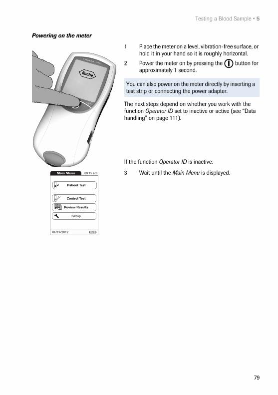
Testing a Blood Sample • 5
79
Powering on the meter
1 Place the meter on a level, vibration-free surface, or hold it in your hand so it is roughly horizontal.
2 Power the meter on by pressing the button for approximately 1 second.
The next steps depend on whether you work with the function Operator ID set to inactive or active (see “Data handling” on page 111).
If the function Operator ID is inactive:
3 Wait until the Main Menu is displayed.
You can also power on the meter directly by inserting a test strip or connecting the power adapter.
Main Menu 09:15 am
04/19/2012
Control Test
Review Results
Setup
Patient Test

5 • Testing a Blood Sample
80
If the function Operator ID is active:
Without operator list:
3 You are now prompted to enter an Operator ID1.
■ Enter the Operator ID using the keypad. Touch to move to the next screen.
■ Alternatively, the Operator ID can also be entered using the built-in barcode scanner2. Touch Scan and scan the operator barcode from a dis-tance of approx. 10 cm (4 inches). The meter beeps once the barcode has been read successfully. The barcode information appears in the operator ID field. The scanner turns off after 10 seconds, if a barcode is not scanned.
1. For configuring operator and patient IDs, see page 117.
Operator ID
A
|B C D E
F G H I J
K L M N O
P Q R S T
U V W X Y
Z 123
09:15 am
Scan
,
2. A list of supported barcode symbologies can be found in Appendix A.3 on page 137.
WARNING
A barcode does not need to be present for the laser scanner to become active. Do not stare directly into the laser beam.

Testing a Blood Sample • 5
81
With operator list:
3 Wait until the operator list is displayed.
4 Select the operator of choice by touching the cor-responding button.
5 Enter the (optional) password.
6 After you enter the password, touch to log on. The Main Menu is displayed and you can start the test.
7 When you touch , the operator pick list is dis-played again.
When the tests are completed or another operator wants to perform additional tests, touch Logout to log out (this button is available only when the Operator ID is acti-vated). The meter returns to the display of the operator pick list.
Note: Extended data handling functionality is depend-ent on the capabilities of the particular Data Manage-ment System (DMS) being used and may vary. For more details see “Data handling”, starting on page 111.
Operator 09:15 am
04/19/2012
Jane Brown
Ann Casey
Joe Dalton
Alan Smithee
Scan
Password
0
|1 2 3 4
5 6 7 8 9
ABC
09:15 am
Main Menu 09:15 am
04/19/2012
Control Test
Review Results
Setup
Patient Test
Logout

5 • Testing a Blood Sample
82
5.3 Performing a test
1 Check the battery level.
2 Check that the date and time are correct. Correct any wrong entries as described in Chapter 4, Meter Setup/“Setting the date”.
If a lockout (Operator or QC Lockout) is displayed instead of the Patient Test button, you must run a liquid quality control test before you can perform a patient test (refer to Chapter 6, Control Testing and Quality Control). When the meter is in lockout status, a test cannot be performed.
The next steps depend on whether you work with or without patient lists.
If the Patient Test button is available, but a lockout is displayed, a test can only be performed as a STAT test (if this function is enabled and if there are still STAT tests available).
For more details on STAT test configuration see pages 71 and 94.
■ If the battery icon turns red (one bar left), there may not be enough power left for another test.
■ If there are no bars left in the battery icon, you cannot perform any more tests. Power the meter off using the
button.
In both cases, restore power by inserting new batter-ies, recharging the battery pack, or using the power adapter.
Main Menu 09:15 am
04/19/2012
Control Test
Review Results
Setup
Patient Test
Main Menu 09:15 am
04/19/2012
Control Test
Review Results
Setup
QC Lockout
Logout
Main Menu 09:15 am
04/19/2012
Control Test
Review Results
Setup
Patient Test
Logout
QC!

Testing a Blood Sample • 5
83
Without patient list
3 Touch Patient Test.
4 If the Patient ID option was chosen as either Optional or Required when the meter was set up (see “Meter Setup”/“Patient ID”), you are prompted to enter a Patient ID1.
■ If Required, enter the Patient ID, then touch to move to the next screen.
■ If Optional, ignore the prompt and touch to move to the next screen. The meter will assign the test a consecutive number.
■ If neither option was chosen, a screen appears that prompts you to insert a test strip.
■ Continue with Step 8.
1. For configuring operator and patient IDs, see page 117.
Patient ID
A
|B C D E
F G H I J
K L M N O
P Q R S T
U V W X Y
Z , 123
09:15 am
Scan

5 • Testing a Blood Sample
84
With patient list
5 Touch Patient Test.
6 Touch and to display the entry of choice. Select the patient to be tested from the list.
7 If the patient is not in the list, touch New to create a new entry. You must now enter a Patient ID using the keypad.
Test 09:15 am
04/19/2012
PID02Jones, Walther
PID03Hamilton, Fran
PID04Miller, Ted
PID01Smith, Henry
New Scan
PID05Reed, William
Patient ID
A
|B C D E
F G H I J
K L M N O
P Q R S T
U V W X Y
Z , 123
09:15 am
Scan

Testing a Blood Sample • 5
85
Alternatively, the Patient ID can also be entered using the built-in barcode scanner1. Touch Scan and scan the patient barcode from a distance of approx. 10 cm (4 inches).
The meter beeps once the barcode has been read suc-cessfully. The barcode information appears in the patient ID field. The scanner turns off after 10 seconds, if a bar-code is not scanned.
Note: Extended data handling functionality is depend-ent on the capabilities of the particular Data Manage-ment System (DMS) being used and may vary. For more details see “Data handling”, starting on page 111.
1. A list of supported barcode symbologies can be found in Appendix A.3 on page 137.
WARNING
A barcode does not need to be present for the laser scanner to become active. Do not stare directly into the laser beam.

5 • Testing a Blood Sample
86
8 The test strip icon prompts you to insert a test strip. Remove a test strip from its container and close the container again with the stopper.
9 Hold the test strip so the lettering with the test name is facing upward.
10 Slide the test strip into the test strip guide in the direction indicated by the arrows.Slide the test strip in as far as it will go. A beep indi-cates that the meter has detected the test strip (provided the beeper is enabled).
Test 09:15 am
04/19/2012
P-ID: PID01Müller, David
Op: SchulzPar: PT
Exposure to external influences (such as humidity) may deteriorate the test strips and may lead to error mes-sages. Therefore, always close the strip container immediately after removing a test strip.

Testing a Blood Sample • 5
87
If you use a new test strip lot and have not inserted the code chip yet, you must do so now. Otherwise you cannot perform a test. The meter displays the number of the code chip belonging to the new test strip lot. Depending on the setting, you may also be required to run a liquid quality control test at this point.
The hourglass icon shows that the test strip is warming up. When the warming-up process is complete, a further beep (provided the beeper is enabled) indicates that you can now apply blood.
The blood drop icon flashes to indicate that the meter is ready to perform the test and is waiting for blood to be applied. A 180 second countdown begins. You must apply the drop of blood to the test strip before the countdown ends. Otherwise you will receive an error message.
Test 09:15 am
04/19/2012
184
P-ID: PID01Smith, Henry
Op: Operator 1Par: PT
Test 09:15 am
04/19/2012
P-ID: PID01
Code: 184
Smith, HenryOp: Operator 1Par: PT
Test 09:15 am
04/19/2012
P-ID: PID01
Code: 184
180 SEC
Smith, HenryOp: Operator 1Par: PT

5 • Testing a Blood Sample
88
11 Now lance the side of a fingertip with the lancing device.
12 Apply the blood (8 μL) directly from the finger to the semicircular, transparent sample application area on top of the test strip.
… or you can touch the blood drop against the side of the sample application area. The test strip draws up the blood by capillary action.During this process you must hold the blood drop to the test strip until the flashing blood drop icon has disappeared and the meter beeps (provided the beeper is enabled).
… you can also apply the blood using the optional CoaguChek capillary tube.
Apply the blood drop to the test strip within 15 seconds of lancing the fingertip. Applying blood after this period of time may lead to an erroneous result (as the coagula-tion process would already have started).
WARNING
Use only a lancing device that is approved for use by healthcare professionals, such as the Accu-Chek Safe-T-Pro or Safe-T-Pro Plus lancing devices, or the Coag-uChek Lancets (professional-use lancets available only in the United States). Follow the manufacturer’s instruc-tions.
We recommend obtaining the capillary blood from the side of the fingertip as this causes the least pain.
Massage the lanced finger gently until a drop of blood is formed. Do not press or squeeze the finger.
Apply the first drop of blood from the finger.
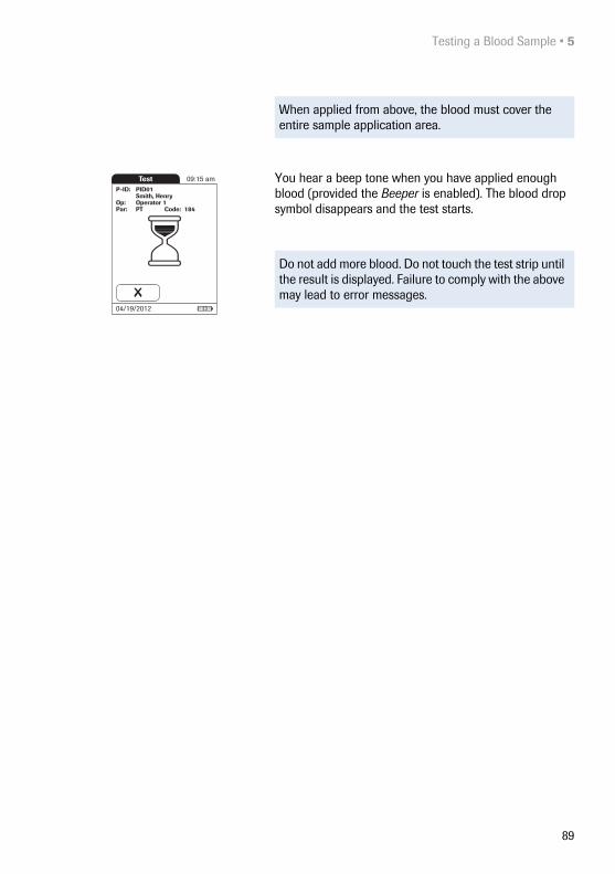
Testing a Blood Sample • 5
89
You hear a beep tone when you have applied enough blood (provided the Beeper is enabled). The blood drop symbol disappears and the test starts.
When applied from above, the blood must cover the entire sample application area.
Do not add more blood. Do not touch the test strip until the result is displayed. Failure to comply with the above may lead to error messages.
Test 09:15 am
04/19/2012
P-ID: PID01
Code: 184
Smith, HenryOp: Operator 1Par: PT

5 • Testing a Blood Sample
90
The meter performs an automatic quality control test on the test strip before it displays the test result. “QC” appears in the display.
Following a successful outcome of the quality control test, a checkmark appears after “QC.”
The result is displayed in the unit you chose when setting up the meter. It is automatically saved.
The valid measuring ranges for CoaguChek XS PT test strips are:
■ INR: 0.8–8.0
■ %Q: 120–5
■ Sec: 9.6–96
Results that are above or below the measuring range are indicated by the symbols > (above) or < (below).
When interpreting results, refer to the detailed informa-tion on limitations and interferences included in the limi-tations section of the test strip package insert.
If a “c” is displayed along with the result:This may occur if the hematocrit value is very low or due to erroneous blood collection (e.g., wet hands). Repeat the measurement and make sure that the patient's hands are dry. If the message persists, perform a hematocrit check.
Test 09:15 am
04/19/2012
P-ID: PID01
Code: 184
Smith, HenryOp: Operator 1Par: PT
QCTest 09:15 am
04/19/2012
P-ID: PID01
Code: 184
2.5INR
Smith, HenryOp: Operator 1Par: PT
21%Q
04/19/2012 09:14 am
Test 09:15 am
04/19/2012
P-ID: PID01
Code: 184
Smith, HenryOp: Operator 1Par: PT
04/19/2012 09:14 am
> 8.0INR
Test 09:15 am
04/19/2012
P-ID: PID05
Code: 208
1.6INR
Müller, DavidOp: SchulzPar: PT
AsymptomaticDoctor Notified
NEW MEDICATION
04/19/2012 09:14 am
C

Testing a Blood Sample • 5
91
Accepting or rejecting a test result
If this function is enabled, you may choose to accept or reject a test result. When the result is displayed, touch
■ Reject or
■ Accept
If you reject a result, you must enter a comment with an explanation.
If you reject the result, this test result is no longer dis-played. However, the test entry is stored.
Test 09:15 am
04/19/2012
P-ID: PID01
Code: 184
2.5INR
Smith, HenryOp: Operator 1Par: PT
Measurement Result OK?
21%Q
04/19/2012 09:14 am
AcceptReject
Comment Required
A comment is required if you reject a result. Please enter a comment.
I-009
Test 09:15 am
04/19/2012
P-ID: PID01
Code: 184
Smith, HenryOp: Operator 1Par: PT
Will Repeat Test
Rejected
04/19/2012 09:14 am

5 • Testing a Blood Sample
92
Adding comments
You can add up to three comments to a test result. Com-ments can provide, for example, additional information about the test conditions or the patient. A comment may be up to 20 characters in length. You can open the func-tion for adding comments directly in the results screen. To add comments:
1 In the Test screen, touch .
2 Select the desired predefined comment(s) from the display list (if configured) or
3 Touch Custom to enter your own custom com-ment. Use the keypad (as with login) to enter your comment.
4 Once you have selected the desired comment(s), touch to return to the results screen.
If you want to add a comment, do not remove the test strip. Once the strip is removed, the meter automatically returns to Main Menu and a comment can no longer be added.
The printer icon only appears if the printer function is activated. Otherwise it is not displayed.
Test results are also saved when the meter is powered off in the results screen or automatically powers off.
Test 09:15 am
04/19/2012
P-ID: PID01
Code: 184
2.5INR
Smith, HenryOp: Operator 1Par: PT
21%Q
04/19/2012 09:14 am
Comment 09:15 am
04/19/2012
Cleaned Meter
Doctor Notified
Sick
Asymptomatic
Custom
Test 09:15 am
04/19/2012
P-ID: PID01
Code: 184
2.5INR
Smith, HenryOp: Operator 1Par: PT
Doctor NotifiedSick
NEW MEDICATION
21%Q
04/19/2012 09:14 am

Testing a Blood Sample • 5
93
After the test result is displayed, touch . You will be prompted to remove the strip.
5 Remove the test strip from the meter.
6 Power the meter off.
7 Clean the meter if necessary (see Chapter 9, Main-tenance and Care).
Remove 09:15 am
04/19/2012
Protection against infection: When collecting samples always observe the general precautions and guidelines relating to blood sampling (see page 14).
Dispose of all test strips used for patient testing in accordance with the disposal policy of your laboratory or practice (see page 14).

5 • Testing a Blood Sample
94
STAT tests STAT tests are a limited number of tests that can be per-formed in emergency situations, see page 71. If the meter is configured to perform STAT tests, you have the option of performing a test by choosing STAT even though a QC Lockout is in place.
1 To perform the measurement without performing a quality control test, touch Patient Test:
2 Touch to confirm the number of remaining STAT tests.
3 Perform the test.
When a STAT test is performed, this information is stored with the result. The number of STAT tests allowed is reduced by 1. After all pending quality control tests are performed, the specified number of STAT tests is availa-ble again in case of a new lockout.
The default setting is three for the number of STAT tests allowed when in QC Lockout.
Main Menu 09:15 am
04/19/2012
Control Test
Review Results
Setup
Patient Test
Logout
QC!
STAT Info
3 STAT tests remaining before lockout.
I-011
Test 09:15 am
04/19/2012
P-ID: PID01
Code: 184
2.5INR
Smith, HenryOp: Operator 1Par: PT
STAT Test
21%Q
04/19/2012 09:14 am

Control Testing and Quality Control • 6
95
6 Control Testing and Quality Control
The CoaguChek XS Pro meter has a number of built-in quality control functions.
■ A check of the electronic components and func-tions every time the meter is powered on.
■ A check of the test strip temperature while a test is in progress.
■ A check of the expiration date and lot information on the test strip carried out by the code chip.
■ A two-level, onboard quality control test and patient result determination within a single test chamber.
Roche offers optional liquid quality controls for the CoaguChek XS Pro system. These controls are provided to assist with regulatory compliance requirements as applicable to your facility.
To perform an optional liquid quality control test using control solutions, you need:
■ CoaguChek XS Pro meter
■ The test strip code chip supplied with the test strip container you are using. A code chip is provided with every test strip pack.
■ Test strips that came with the code chip mentioned above
■ Bottles of CoaguChek XS PT Controls (not available in the United States) or CoaguChek XS Pro PT Con-trols, diluent droppers, and the quality control code chip provided.
You can choose the frequency of liquid quality control tests in the meter setup. (Refer to the chapter entitled “Meter Setup”/“QC (quality control) Lockout” starting on page 67). If the control results in the display are in the specified range, this confirms that the liquid control test was performed correctly.

6 • Control Testing and Quality Control
96
6.1 Preparing to run a liquid quality control test
Prepare for a liquid quality control test in the same way you would prepare to perform a test with a capillary blood sample. The only difference is the use of control solution instead of blood.
1 Have the test strip container at hand.
2 If you are using the test strip lot for the first time, make sure that the code chip that came with these test strips is at hand.
3 Make sure the bottle of freeze-dried (lyophilized) con-trol plasma and the dropper for making the control solution are at hand. This bottle should remain refrig-erated (not frozen) until use.
4 Make sure that the quality control code chip that came with the control solution is at hand.
5 Open the lid of the bottle and remove the rubber cap.
6 Hold the dropper with the sealed dropper neck point-ing upward, then cut off the end of the cap with scis-sors. Do not hold the dropper close to your face.
To avoid loss of diluent, hold the dropper by the stem; do not squeeze the bulb of the dropper while cutting the tip.

Control Testing and Quality Control • 6
97
7 Apply gentle pressure to the reservoir to transfer the entire contents of the dropper to the bottle. Make sure that the dropper does not come into contact with the dried control plasma.
8 Close the bottle again.
9 Make sure the dropper is at hand for the next steps in the liquid quality control test.
10 Swirl the bottle using a circular motion to com-pletely dissolve all of the control plasma inside. Do not shake the bottle or turn it on its side. Doing so can cause components in the control plasma to stick to the sides of the bottle. Please refer to the control solution package insert.
The control solution is now ready to be applied to the test strip.
The control solutions may be reconstituted (mixed) after removal from the refrigerator. The resulting solution may be used up to 30 minutes after reconstitution.

6 • Control Testing and Quality Control
98
6.2 Performing a liquid quality control test
1 Place the meter on a level, vibration-free surface or hold it in your hand so it is roughly horizontal.
2 Power the meter on by pressing the button for approximately 1 second.
You can also power on the meter directly by inserting a test strip or connecting the power adapter.
3 Wait until the Main Menu is displayed, or log on as described on page 80.
4 Check the battery level.
5 Check that the date and time are correct. Correct any wrong entries as described in Chapter 4, Meter Setup/“Setting the date”.
■ If the battery icon turns red (one bar left), there may not be enough power left for another test.
■ If there are no bars left in the battery icon, you cannot perform any more tests. Power the meter off using the
button. In both cases, restore power by inserting new batteries, recharging the battery pack, or using the power adapter.
Main Menu 09:15 am
04/19/2012
Control Test
Review Results
Setup
Patient Test

Control Testing and Quality Control • 6
99
6 Touch Control Test.
7 The test strip icon prompts you to insert a test strip. Remove a test strip from its container and close the container again with the stopper.
8 Hold the test strip so the lettering with the test name is facing upward.
9 Slide the test strip into the test strip guide in the direction indicated by the arrows. Slide the test strip in as far as it will go.
A beep tone indicates that the meter has detected the test strip (provided the beeper is enabled).
Exposure to external influences (such as humidity) may deteriorate the test strips and may lead to error mes-sages. Therefore, always close the container immedi-ately after removing a test strip.
Main Menu 09:15 am
04/19/2012
Control Test
Review Results
Setup
Patient Test
QC Test 09:15 am
04/19/2012
Op: SchulzPar: PT

6 • Control Testing and Quality Control
100
If you are using a new test strip lot and have not inserted the test strip code chip yet, you must do so now. Other-wise you cannot perform a quality control test.
As with the test strips, a quality control code chip is also provided with the control solutions. This chip informs the meter about the acceptable ranges of results for that lot of controls. The information on the code chip is retained in the memory so you can use the same control solutions at any time.
10 Select the code stored for your current control solu-tion, or touch New Code to use a new control solu-tion.
If you are using a new control solution, remove the strip code chip from the meter and insert the code chip that came with the control solution instead.
The first time you run a control, the meter skips this QC Test screen option because there are no code chip parameters in memory yet. The next time you use the control, this screen will display, offering you a pick of the code(s) already stored as well as the option New Code.
If the code chips get mixed up, check the letter on the code chips to tell them apart. A capital S in front of the number indicates that this code chip is for test strips. A capital C in front of the number indicates that it is a control solution code chip.
QC Test 09:15 am
04/19/2012
184Op: Operator 1
QC Test 09:15 am
04/19/2012
QC 070
QC 060
QC 050
New Code
QC 048
*
QC Test 09:15 am
04/19/2012
Code: 184Op: Operator 1
Par: PT
QC

Control Testing and Quality Control • 6
101
11 If performing more than one level, select the level for this measurement.
The hourglass icon shows that the test strip is warming up. When the warming-up process is complete, a further beep (provided the beeper is enabled) indicates that you can now apply the control solution.
The dropper icon flashes to indicate that the meter is ready to perform the test and is waiting for the sample to be applied.
At the same time a 180-second countdown begins. You must apply the sample within this time, otherwise you will receive an error message.
QC Test 09:15 am
04/19/2012
180 SEC
QC: 999Code: 184Op: Operator 1
Par: PTLevel: 1
QC Test 09:15 am
04/19/2012
QC: 999Code: 184Op: Operator 1
Par: PTLevel: 1
QC Test 09:15 am
04/19/2012
QC: 999Code: 184Op: Operator 1
Par: PT
Level 1
Level 2

6 • Control Testing and Quality Control
102
12 Using the dropper, draw up the dissolved contents of the bottle.
13 Apply a single drop of control solution directly from the dropper to the semicircular, transparent sample application area on top of the test strip. Do not add more control solution.

Control Testing and Quality Control • 6
103
You hear a beep when you have applied enough control solution (provided the beeper is enabled). The dropper icon disappears and the test starts.
The result of the liquid quality control test is displayed. It is automatically saved to memory.
The acceptable range of results for the liquid control is displayed below the current result, along with Pass or Fail.
If a quality control test fails, an up arrow (too high) or down arrow (too low) is displayed and flashes.
Note: The arrow (next to the result) refers to the INR result only.
If you have selected to display INR and %Quick or INR and seconds, the (up or down) arrow next to the result refers only to the INR value.
The printer icon only appears if the printer function is activated. Otherwise it is not displayed.
QC Test 09:15 am
04/19/2012
0.9 INRFail:
110 %Q
04/19/2012 09:15 am
QC: 999Code: 184Op: Operator 1
Par: PTLevel: 1
(1.0 - 1.4 INR)
(53 - 99 %Q)
QC Test 09:15 am
04/19/2012
1.2 INR
78 %Q
04/19/2012 09:15 am
QC: 999Code: 184Op: Operator 1
Par: PTLevel: 1
(1.0 - 1.4 INR)
(53 - 99 %Q)
Pass:
QC Test 09:15 am
04/19/2012
QC: 999Code: 184Op: Operator 1
Par: PTLevel: 1

6 • Control Testing and Quality Control
104
14 If you want to add a comment, touch .
15 Select the desired predefined comment(s) from the pick list (if configured) or
16 Touch Custom to enter your own custom com-ment. Use the keypad (as with login) to enter your comment. A comment may be up to 20 characters in length.
17 Once you have selected the desired comment(s), touch to return to the results screen.
After the test result is displayed, touch . You will be prompted to remove the strip.
18 Remove the test strip from the meter.
19 Power the meter off.
20 Remove the quality control code chip from the meter and store it with the controls.
21 Clean the meter if this becomes necessary (see Chapter 9, Maintenance and Care).
If you are performing a 2-level control, you will now be asked to proceed with the second level.
QC Comment 09:15 am
04/19/2012
New Control Lot
Cleaned Meter
Doctor Notified
Acceptable Control
Custom
Remove 09:15 am
04/19/2012
Dispose of controls and used test strips from control test-ing in accordance with the disposal policy of your facility. The control solution contains animal material, which should be considered as potentially infectious.

Review Results • 7
105
7 Review Results
The CoaguChek XS Pro meter can save 2000 patient test results as well as 500 liquid quality control tests to mem-ory, together with respective time and date. In addition, up to 60 code chip records (contents of test strip code chips and control solution code chips) are stored. If you are using operator and/or patient lists, a maximum of 5000 Operator and 4000 Patient IDs is allowed.
If memory is full when you perform a test, the oldest result is automatically deleted. The most recent result is always saved. This applies both to patient results and to quality control tests. In order to avoid the loss of stored test results, you can archive this data using a data man-agement system and the optional Handheld Base Unit (see page 111).

7 • Review Results
106
7.1 Viewing test results
1 Place the meter on a level, vibration-free surface, or hold it in your hand so it is roughly horizontal.
2 Power the meter on by pressing the button for approximately 1 second.
3 Wait until the main menu is displayed.
To power the meter off after use, press the button for approximately 1 second.
Main Menu 09:15 am
04/19/2012
Control Test
Review Results
Setup
Patient Test

Review Results • 7
107
4 Touch Review Results.
5 Select the type of results you want to view.
■ Display Patient Result memory
■ Display QC Result memory
The following buttons for general use are located in the views described below:
Menu icon: Return to main menu
Return icon: From the single-result display, return to the list of results
Individual icon: List that contains entries for this patient only
Printer icon: The printer icon only appears if the printer function is activated. Otherwise it is not displayed.
Main Menu 09:15 am
04/19/2012
Control Test
Review Results
Setup
Patient Test
Memory 09:15 am
04/19/2012
QC Result
Patient Result

7 • Review Results
108
Display patient result memory This memory area contains all test results for your patients, sorted according to the setting you chose for the option Sort (see page 46). If the Sort option is set to Date/Time, the most recent results are at the top of the list.
1 Touch and to scroll to the entry of choice on the screen.
2 Touch the entry you want to open.
The entry is displayed.
3 Touch . The results for the selected patient are displayed.
Memory 09:15 am
04/19/2012
P-ID: PID01
Code: 184
2.5INR
Smith, HenryOp: Operator 1Par: PT
Doctor NotifiedSick
Travel
21%Q
04/18/2012 11:31 am
Memory 09:15 am
04/19/2012
P-ID: PID01Smith, Henry
04/18/2012 11:31 am2.5 INR 21 %Q
04/17/2012 10:15 am3.0 INR 16 %Q
04/16/2012 09:58 am1.7 INR 38 %Q
Memory 09:15 am
04/19/2012
PID0104/17/2012 10:10 am
PID0104/16/2012 10:07 am
PID0104/15/2012 10:01 am
PID0104/18/2012 11:31 am
PID0104/14/2012 10:03 am

Review Results • 7
109
Display QC (quality control) result memory
This memory area contains all liquid quality control tests that were run, sorted chronologically. The most recent results are at the top of the list.
1 Touch and to scroll to the entry of choice on the screen.
2 Touch the entry you want to open.
The entry is displayed.
Memory 09:15 am
04/19/2012
1.2 INR
New Control LotNew Strip Lot
78 %Q
04/18/2012 11:31 am
QC: 999Code: 184Op: Operator 1
Par: PTLevel: 1
(1.0 - 1.4 INR)
(53 - 99 %Q)
Pass:
QC 09:15 am
04/19/2012
04/17/2012 10:05 am QC 234 Pass
04/16/2012 10:07 am QC 623 Pass
04/15/2012 10:30 am QC 333 Pass
04/18/2012 11:31 am QC 999 Pass
04/14/2012 11:01 am QC 432 Pass

7 • Review Results
110
This page intentionally left blank.

Extended Functionalities • 8
111
8 Extended Functionalities
8.1 Data handling
When used in conjunction with the Handheld Base Unit from Roche (available separately), the CoaguChek XS Pro meter can conveniently connect to a data management system (DMS). The main advantages of such a connec-tion between meter and DMS may include:
■ Transferring patient lists, operator lists, and settings from the DMS to the meter. In this way the setup for daily work as well as general meter setup can be performed (for one or more meters) quickly and conveniently.
■ Transferring all stored test results with the corre-sponding Patient ID, Operator ID, and comments from the meter to the DMS. This transfer of data permits further evaluation or proper archiving according to your needs.
Note: Extended data handling functionality is depend-ent on the capabilities of the particular Data Manage-ment System (DMS) being used and may vary.

8 • Extended Functionalities
112
Through the DMS the system administrator (such as the POC coordinator) may specify what settings are to be applied to a set of meters within a site or unit (e.g., hospi-tals or wards). All meters assigned to a specific site and/or unit would consequently share the same settings. The different operator and patient lists (that match a site or unit) are then made available on their respective meters. Other settings such as QC Lockout and Operator Lockout may easily be set (once) and distributed to all meters.
The option of setting up an Operator Lockout is availa-ble only when operator lists are created on the DMS, stored in the meter, and Operator login is activated. For more details on Operator login see page 60, for details on Operator Lockout see page 69.
When using operator and/or patient lists and the lists are set to be hidden, operator login and/or patient selection is only possible via barcode scanner.
All setup options that allow using the barcode scanner (e.g., Operator login, Patient ID entry) require the used barcode types to be activated in the DMS and trans-ferred to the meter before scanning. Otherwise bar-codes cannot be scanned.

Extended Functionalities • 8
113
Computer (Setup option) For initial connection to a DMS, the ability to communi-cate within a network has to be set up as follows:
■ In the Setup menu, the Connection option must be set to Computer (see page 51).
■ The Handheld Base Unit must be configured cor-rectly. (For details please refer to the manual of the Handheld Base Unit and the Technical Note stored on the Handheld Base Unit itself.)
■ Place the meter on a Handheld Base Unit that is connected to the network. The meter will automat-ically be recognized by the DMS and may now be assigned to a site and/or unit managed by the DMS (if your DMS has that functionality).
■ Depending on DMS functionality available, the DMS may transfer settings and lists to the meter as well as enable test results to be transferred from the meter to the DMS.

8 • Extended Functionalities
114
Operator lists After powering the meter on, an Operator login may be configured. There are three possible configurations for an Operator login:
■ Operator list is activated, but there are no operators available:The Operator can either log in via the onscreen keypad or a barcode scan. The use of the meter is not restricted to a predefined Operator group. The operator ID is stored together with each test result for informational purposes only.
If an operator list is available on the meter, there are two options:
■ Operator list is activated and available on the meter: The Operator can either select the ID from the dis-played list on the login screen, or scan the ID using the barcode scanner.If so configured by the Administrator, the Operator may also be required to enter a password to log in.
■ Operator list is activated and available on the meter but set to “hidden”:The Operator can only log in via a barcode scan. If so configured by the Administrator, the Operator may also be required to enter a password to log in.
This first configuration is also available without a DMS.
When working with operator lists: The use of the meter is restricted only to certified operators contained in the list. If the Scan button or the operator list are not dis-played on the meter, the operator certification has to be checked.

Extended Functionalities • 8
115
Patient lists When starting a Patient Test, there will be the option of either selecting a Patient ID from a patient list, entering the Patient ID using the onscreen keypad or, if available, of scanning the barcode with the Patient ID. The Patient ID, if entered on the DMS, comes with an additional iden-tification entry. Up to 20 characters can be used and assigned as a second confirmation (e.g., name, date of birth).
There are four possible configurations for a Patient ID input:
■ The Patient ID is set to Optional or Required, and there is no list available:A Patient ID can be entered manually via the onscreen keypad or read in via a barcode scan. The Patient ID is stored with the test result.
■ The Patient ID is set to No, but there is a list available:The list of Patient IDs is always shown when starting a test. You may now
– select a patient from the list;
– scan a Patient ID using the barcode scanner;
– create a new patient entry by touching New. Instead of an ID a consecutive number will be assigned to this result.
■ The Patient ID is set to Optional or Required, and there is a list available:The list of Patient IDs is always shown when start-ing a measurement. You may now
– select a patient from the list;
– scan a Patient ID using the barcode scanner;
– create a new patient entry by touching New. You may either read the ID using the barcode scanner or enter a new ID via the onscreen keypad.

8 • Extended Functionalities
116
■ The Patient ID is set to “hidden” (only possible with a data management system), and there is a list available:When you start the test, the screen is blank and Scan is displayed.
– You may now scan a Patient ID using the barcode scanner. If the patient ID is on the list, the test will proceed. If the patient ID is not on the list, you will get an error message.
Patient list validation Depending on DMS settings, you have the following options for patient list validation when working with Patient lists:
■ A Patient ID does not have to be on the list to be used (only valid for validation mode “off”).
■ The meter displays a notification if the Patient ID entered is not on the list and validation mode “notify” was selected in the DMS.
■ The meter displays an error message if the ID was not found on the list of valid Patient IDs and valida-tion mode “required” was selected in the DMS. To proceed with the test, you must scan (if ID set to “hidden”) or select (if ID set to Required) a valid Patient ID.
■ If the “list” feature is set to be hidden, only Patient IDs which are part of the patient list (previously transferred from the DMS to the meter) can be selected. It is not possible to add new Patient IDs via scanner or keypad.
Note that the scanned Patient ID must already be on the list that is sent from the DMS to the meter. You cannot use the scanner to scan and enter a new Patient ID if the Patient ID is set to “hidden”.
Extended Functionalities • 8
117
Configuring operator and patient IDs
When creating operator and patient IDs, apply the follow-ing rules:
■ Patient IDs can consist of up to 20 alphanumeric characters, with specified minimum and maximum lengths.
■ Operator IDs can consist of up to 20 alphanumeric characters.
Barcode scanner Using a DMS, the barcode scanner may be configured to accept only selected barcode symbologies. A list of sup-ported barcode symbologies can be found in Appendix A on page 137.
Stored test results and comments
When performing a test, the test result will be stored along with additional information, including the Patient ID, Operator ID, the kind of test performed, and optional Comments. The meter comes with a default set of Com-ments that can be assigned to each test result. If you are working with a DMS, these comments can be replaced by the comments in the DMS. The new wording will then be available for selection from the Comments list in the meter.
Alphanumeric characters are any combination of A - Z and 0 - 9, additionally “.” (period), or “-” (hyphen) may be used.
Barcode masking can be used to eliminate any charac-ters not belonging to the Operator ID. See information on “Operator and patient ID barcode masks” on page 136.
Up to 3 comments can be assigned to each result.
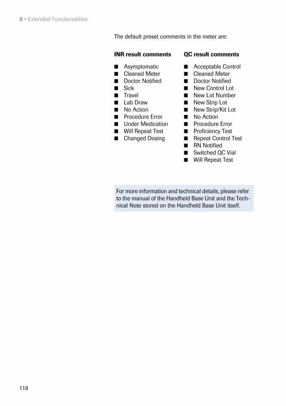
8 • Extended Functionalities
118
The default preset comments in the meter are:
INR result comments QC result comments
■ Asymptomatic■ Cleaned Meter ■ Doctor Notified ■ Sick ■ Travel ■ Lab Draw ■ No Action ■ Procedure Error ■ Under Medication ■ Will Repeat Test ■ Changed Dosing
■ Acceptable Control■ Cleaned Meter■ Doctor Notified■ New Control Lot■ New Lot Number■ New Strip Lot■ New Strip/Kit Lot■ No Action■ Procedure Error■ Proficiency Test■ Repeat Control Test■ RN Notified■ Switched QC Vial■ Will Repeat Test
For more information and technical details, please refer to the manual of the Handheld Base Unit and the Tech-nical Note stored on the Handheld Base Unit itself.

Maintenance and Care • 9
119
9 Maintenance and Care
9.1 Conditions for storage and shipping
Storage ■ Store the system and test strips in the same envi-ronment in which they are used.
■ Do not store the meter in direct sunlight or under extreme temperature conditions.
■ Observe the limits for temperature and humidity when storing and using the meter (see Chapter 11).

9 • Maintenance and Care
120
Shipping
■ If the meter is shipped or transported over long dis-tances, always remove the battery pack from the meter. This eliminates the possibility of the battery pack overheating due to a short-circuit in the meter. It also prevents deep discharge and other damage to the battery pack or meter.
■ Only ship undamaged battery packs. Damaged bat-tery packs must be disposed of locally. See page 16 for the risks associated with damaged battery packs and disposal information.
■ Package the battery pack for shipping so that it cannot move around in the packaging. Also observe any other applicable national regulations.
■ When shipping via third parties (e.g., by air or parcel service), work with the carrier to check whether specific requirements need to be met in relation to the lithium-ion battery packs on the basis of national or international laws on hazardous goods and, where applicable, if special packaging and labeling requirements apply.
Observe the following safety information when shipping the meter and battery pack. Failure to do so may result in injury to persons or damage to the meter or battery pack.
For short distances - example between a facility’s sites - users may transport the battery packs (either installed in the meter or separately) by road without having to meet further requirements.

Maintenance and Care • 9
121
9.2 Cleaning and Disinfecting the Meter
Difference between cleaning and disinfecting
Cleaning is the physical removal of organic soiling (e.g., dirt, or other foreign material) from the meter surface.
Disinfecting is the removal of most, but not all, disease-causing and other types of microorganisms (blood-borne pathogens) from the meter.
When should the meter be cleaned and disinfected?
■ Clean the meter to remove visible soil and organic material for safe handling and/or prior to disinfecting.
■ The exterior of the meter and the test strip guide should be cleaned and disinfected before being used on another patient.
■ Maintenance cleaning: The use of the disinfecting cloths may lead to a build-up of residue on the test strip guide and battery compartment that needs to be removed. Frequency: whenever residue build-up is visible or at least once per month.
■ Disinfect the meter when it is soiled and per your facility’s guidelines.
What to clean and disinfect? The following parts of the meter may be cleaned /disinfected:
■ The area around the test strip guide
■ The meter display (touchscreen)
■ The meter housing (entire meter surface - front and back)
■ The test strip guide and test strip guide cover

9 • Maintenance and Care
122
Follow the instructions given below to clean and disinfect the meter. Failure to follow these instructions may cause malfunction of the meter.
■ Observe the disinfection guidelines of your institution.
■ Use gloves.
NOTICE Instrument damage due to moistureEnsure that no liquid enters the meter. If moisture enters the meter, it may cause malfunction of the instrument.
■ Make sure the meter is turned off.■ Do not spray anything onto the meter housing.■ Do not spray into the test strip guide.■ Do not immerse the meter in liquid.■ Do not use cloths or swabs/buds that are saturated.
Squeeze off excess solution or blot on a dry paper towel to remove any excess solution before wiping the surface of the meter.

Maintenance and Care • 9
123
9.3 Recommended cleaning/disinfecting agents
Use only the following solutions for cleaning/disinfecting the meter (housing and test strip guide).
■ A soft cloth slightly dampened (not wet) with a small amount of liquid soap diluted in water
■ Rubbing alcohol (70% ethanol or isopropyl alcohol)
■ Alcohol-based disinfectant (a mixture of 1-propanol (400mg/g), 2-propanol (200 mg/g) and glutaraldehyde (1.0 mg/g)) 1
■ 10% sodium hypochlorite solution (1 part bleach to 9 parts de-ionized water, made fresh every 24 hours)
■ Disposable wipes containing quaternary ammo-nium compounds up to 0.5 % (single compound or mixture) in isopropyl alcohol (isopropanol) up to 55 %
1. Sold in some countries under the name “Bacillol Plus.”
NOTICE Do not use any other disinfectants/cleaning solutions on the meter (housing or test strip guide). Use of other dis-infectants/cleaning solutions could result in damage to the meter.

9 • Maintenance and Care
124
9.4 Cleaning/disinfecting the exterior (meter housing)
Use the solutions recommended on page 123 for clean-ing/disinfecting the meter exterior. Apply the solutions for a contact time of > 1 minute (refer to the corresponding product labeling).
1 Power off the meter. Then gently wipe over the sur-faces (touchscreen, housing) with a soft, lint-free cloth slightly dampened (not wet).
2 With a fresh dry cloth or lint-free tissue, wipe away residual moisture and fluids after cleaning the housing. Visually verify that no solution is seen any-where on the housing or touchscreen at the com-pletion of cleaning and disinfecting.
3 Allow wiped areas to dry for at least 10 minutes before performing the next patient test.
Ensure that the blue test strip guide cover remains tightly closed while cleaning the meter housing.
Do not let liquid accumulate near any opening. Ensure that no liquid enters the meter.
If you notice streaks on the housing or touchscreen, or the touchscreen surface becomes slightly cloudy, wipe clean immediately with a soft, lint-free cloth slightly dampened with water.

Maintenance and Care • 9
125
9.5 Cleaning/disinfecting the test strip guide
Use the solutions recommended on page 123 for clean-ing/disinfecting the test strip guide. Apply the solutions for a contact time of > 1 minute (refer to the correspond-ing product labeling) using lint-free cotton swabs/buds.
1 With the meter powered off, remove the test strip guide cover to clean it. (Use your thumbnail to open the cover of the test strip guide by pressing its front edge upward.) Move the cover safely away from the meter. Then rinse the cover with warm water or wipe it clean using the solutions recommended above. Let the test strip guide cover dry for at least 10 minutes before re-attaching it.
2 Hold the meter upright with the test strip guide facing down.
■ Clean the easily accessible white areas with a mois-tened cotton swab/bud.
■ Ensure the swab/bud is only damp, not wet. Wipe away residual moisture and fluids.

9 • Maintenance and Care
126
On completion of cleaning:
3 With the cover off, let the test strip guide dry for at least 10 minutes before re-attaching the test strip guide cover and testing again.
■ Visually verify that no residual moisture is seen any-where on the test strip guide and cover at the com-pletion of cleaning and disinfecting.
■ Ensure that the test strip guide and cover are com-pletely dry before assembling them.
4 Re-attach the test strip guide cover to the housing. Make sure that the cover is properly closed. You will hear it snap into place.
9.6 Cleaning the scanner window
The scanner window should be cleaned periodically. Use a clean, dry cloth to wipe the scanner window.
NOTICE Damage to the instrument■ Ensure that no liquid enters the meter when clean-
ing the test strip guide. If moisture enters the meter, it may cause malfunction of the instrument.
■ Do not insert any objects in the test strip guide. Doing so may damage the electrical contacts behind the test strip guide.
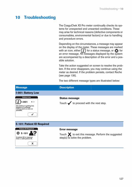
Troubleshooting • 10
127
10 Troubleshooting
The CoaguChek XS Pro meter continually checks its sys-tems for unexpected and unwanted conditions. These may arise for technical reasons (defective components or consumables, environmental factors) or due to handling and procedure errors.
Depending on the circumstances, a message may appear on the display of the meter. These messages are marked with an icon, either for a status message, or for an error message. All messages displayed by the system are accompanied by a description of the error and a pos-sible solution.
Take the action suggested on screen to resolve the prob-lem. If the error disappears, you may continue using the meter as desired. If the problem persists, contact Roche (see page 139).
The two different message types are illustrated below:
Message Description
I-001: Battery Low
Status message
Touch to proceed with the next step.
E-101: Patient ID Required
Error message
Touch to exit this message. Perform the suggested step(s) to solve the problem.
Battery Low
The battery is getting low. Replace or recharge battery pack as soon as possible.
I-001
Patient ID Required
A patient ID is required. Enter a valid patient ID.
E-101

10 • Troubleshooting
128
Additional information on error E-406
Power the meter off and remove the test strip. Repeat the measurement using a new test strip and blood taken from a new puncture site at the tip of another finger. Do not touch or remove the test strip when a test is in progress.
Note on error E-406: The CoaguChek XS PT Test strip may be used for patients under a combination therapy of oral anticoagulants plus heparin injections. For maximum heparin concentrations which do not interfere with the test, refer to the package insert. Under no circumstances, however, should heparinized capillary tubes be used for sample application. If capillary tubes are used, use only the dedicated CoaguChek capillary tubes. Be sure to apply the blood drop to the test strip within 15 seconds of lancing the fingertip. In rare cases, patients with long clotting times (> 8 INR; < 5% Quick) may receive an “E-406” message on the meter display. If this error mes-sage appears again when the test is repeated, the result must be checked using another method.
E-406: Sample Error
Error message
Touch to exit this message. Perform the suggested step(s) to solve the problem.
Sample Error
Unsuitable sample composition. Check your procedure and repeat the test with a fresh sample. Check medication regimen of patient.
E-406

Troubleshooting • 10
129
Errors and unusual behavior without error messages
Some conditions may arise that have no associated error or status message.
Message Description
No message or unusual behavior
Meter display does not power on ■ Wait 10 seconds and try powering on the unit again.■ Check that the meter has power.
• If you are using the external power adapter, is it connected properly to the meter?Or:
• Place the meter in the Handheld Base Unit.Or:
• If you are using the Handheld Battery Pack, is it properly installed in the meter?
Meter displays an unexpected result Refer to the package insert for the test strips.
Automatic shutdown
The meter powers off after a configurable time without activity (e.g., pressing a key, touching the screen) to con-serve energy. Reactivate the meter/screen as described in the following:
Shutdown after time specified by system administrator (default is 5 min-utes, configurable by system adminis-trator)
■ Press the On/Off button of the meter.

10 • Troubleshooting
130
This page intentionally left blank.
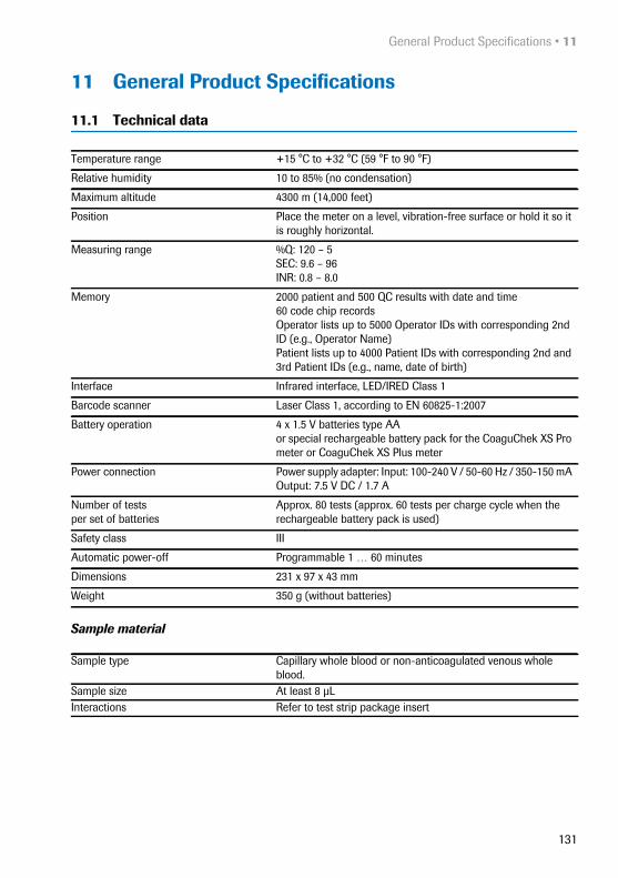
General Product Specifications • 11
131
11 General Product Specifications
11.1 Technical data
Sample material
Temperature range +15 °C to +32 °C (59 °F to 90 °F)
Relative humidity 10 to 85% (no condensation)
Maximum altitude 4300 m (14,000 feet)
Position Place the meter on a level, vibration-free surface or hold it so it is roughly horizontal.
Measuring range %Q: 120 – 5SEC: 9.6 – 96INR: 0.8 – 8.0
Memory 2000 patient and 500 QC results with date and time60 code chip recordsOperator lists up to 5000 Operator IDs with corresponding 2nd ID (e.g., Operator Name)Patient lists up to 4000 Patient IDs with corresponding 2nd and 3rd Patient IDs (e.g., name, date of birth)
Interface Infrared interface, LED/IRED Class 1
Barcode scanner Laser Class 1, according to EN 60825-1:2007
Battery operation 4 x 1.5 V batteries type AAor special rechargeable battery pack for the CoaguChek XS Pro meter or CoaguChek XS Plus meter
Power connection Power supply adapter: Input: 100-240 V / 50-60 Hz / 350-150 mA Output: 7.5 V DC / 1.7 A
Number of testsper set of batteries
Approx. 80 tests (approx. 60 tests per charge cycle when the rechargeable battery pack is used)
Safety class III
Automatic power-off Programmable 1 … 60 minutes
Dimensions 231 x 97 x 43 mm
Weight 350 g (without batteries)
Sample type Capillary whole blood or non-anticoagulated venous whole blood.
Sample size At least 8 μLInteractions Refer to test strip package insert

11 • General Product Specifications
132
Storage and transport conditions
* At temperatures above +50 °C/122 °F the batteries could leak and damage the meter. At temperatures below -10 °C/+14 °F the batteries do not have enough power to keep the internal clock functioning.
11.2 Further Information
Ordering The following configurations are available.
Reagents and solutions Supplies are available through Roche Diagnostics. Con-tact your local Roche representative.
Product limitations Please read the information in the package insert sup-plied with the test strips for detailed product data and limitations.
Temperature rangeMeter (without batteries)
–25 °C to +70 °C (-13 °F to +158 °F)
Temperature rangeMeter (with batteries)*
–10 °C to +50 °C (+14 °F to +122 °F)
Relative humidity 10 to 85 % (no condensation)
Item Description RemarksCoaguChek XS PT Test 24 test strips International edition
(not available in the US)
CoaguChek XS PT Test 2 x 24 test strips
CoaguChek XS PT Controls Optional liquid controls for the CoaguChek XS Pro / XS Plus systems
International edition (not available in the US)
CoaguChek XS Pro PT Controls Optional liquid controls for the CoaguChek XS Pro / XS Plus systems
US edition
CoaguChek Capillary Tubes/Bulbs Capillary tubes
Handheld Battery Pack Rechargeable battery pack
Handheld Base Unit Kit Handheld Base Unit and Operator’s Manual

General Product Specifications • 11
133
Information about software licenses
This product incorporates software modules developed under open source licenses. The source code of this soft-ware can be requested on a standard data exchange medium from the manufacturer at the following address:
Roche Diagnostics GmbHSandhofer Str. 11668305 Mannheim, Germany
The General Public License (GPL) licensing conditions are available (in English only for legal reasons) as a PDF file (file name “License.txt.PDF”) on the CD supplied with this manual. The complete license agreements are also stored as a text file (file name “License.txt”) on the Hand-held Base Unit. You can access this file by connecting the base unit to a PC with the USB cable. For detailed instruc-tions on how to do this, see the Operator's Manual of the Handheld Base Unit.
Everyone is permitted to copy and distribute verbatim copies of this license document, but changing it is not allowed.
Repairs Please note that repairs and other modifications to the meter may only be performed by persons authorized by Roche.

12 • Warranty
134
Contact Roche For all questions about the CoaguChek XS Pro system that are not answered in this manual, contact your Roche Diagnostics representative. If you do not already have contact details:
■ Visit our website at www.roche.com. Select “Roche in your country” at the top of the page and then select your country to find the appropriate local office contact information, or:
■ Visit our website at www.coaguchek.com. Locate the “CoaguChek Worldwide” box on the page and select your country.
The CoaguChek XS Pro system is manufactured for and distributed by:
In the United States:
Roche Diagnostics9115 Hague RoadIndianapolis, IN 46256
In Australia:
Roche Diagnostics Australia Pty LimitedABN 29 003 001 20531 Victoria AvenueCastle Hill, NSW, 2154
12 Warranty
The statutory guarantee provisions on rights in consumer goods sales in the country of purchase shall apply.

Appendix • A
135
A Appendix
A.1 Working with barcodes
To reduce the probability of the barcode being misread, it is strongly recommended that you use the configuration options for patient and/or operator ID validation as appli-cable to your specific workflow. These options are:
■ check ID against list or
■ check ID for length1
■ check if the scanned bar code type is allowed and activated in the DMS.
In combination with the above options or as a single measure, use an appropriate barcode mask if this is com-patible with the structure of your barcode content.
Always make sure that the entire barcode is covered by the red laser beam when scanning.
WARNING
Risk of barcode read errorsIf a barcode is read incorrectly, this may lead to patient misidentification and therefore to inappropriate therapy decisions.
To minimize the risk of barcode read errors, the facility must ensure that the barcode used is of adequate size and print quality. In addition, every user must carry out a plausibility check on all data scanned into and displayed by the instrument.
1. If no operator/patient list can be used, it is recommended that you at least set a minimum length for the respective ID, even if your facility uses IDs of varying length.

A • Appendix
136
A.2 Operator and patient ID barcode masks
Barcode mask character Definition
A-Z, 0-9 If not preceded by the Caret (“^”), the scan data character must be the same as the mask character. This character is not saved as part of the ID. If the characters are not the same, the scan data is not a valid ID.
Dollar (“$”) The scan data character in this position is kept as part of the ID.
Asterisk (“*“) The scan data character in this position is not kept as part of the ID.
Tilde (“~”) The scan data character in this position must be a number, 0-9, and it is not kept as part of the ID. If the scan data character is not a number, the scan data is not a valid ID.
Plus (“+”) The scan data character in this position must be an alpha character, A – Z, and it is not kept as part of the ID. If the scan data character is not an alpha character, the scan data is not a valid ID.
Caret (“^”) This mask character denotes that the scan data character must be equal to the next character in the barcode mask after the “^”, and that the scan data character is kept as part of the ID. If the scan data character is not equal to the mask character following the “^”, the barcode reading is invalid as an ID.

Appendix • A
137
A.3 Example of barcode symbologies
The barcode samples shown here are for illustration purposes only. If printed out, they can be used to check the barcode scanner. However, they are not meant to be used as a reference for size or resolution of real patient or operator ID barcodes. Always refer to the relevant standard ISO/IEC 15421 for size and resolution require-ments when creating patient or operator barcodes.
When creating patient or operator barcodes, always adhere to the applicable international IEC/ISO standards for the respective barcode symbology. In particular, ensure that barcode size and print quality (as defined in ISO/IEC 15421) are adequate. Inadequate print size and/or quality may lead to erroneous decoding.
WARNING
Avoidance of incorrect EAN 13 and Interleaved 2/5 barcode readingsEAN 13 and Interleaved 2/5 barcodes, although widely used, are not recommended for patient/operator bar-codes. If an EAN 13 or Interleaved 2/5 barcode is read incorrectly, this may lead to patient misidentification and therefore to inappropriate therapy decisions. If used nonetheless:
■ make sure that the very highest quality standards of barcode creation and reproduction are applied
■ for EAN13: do not use the start sequences 978 (ISBN) and 979 (ISMN) as they will be ignored as a part of any ID code

A • Appendix
138
Codabar Code 39
Code 93 Code 128
EAN 13 Interleaved 2/5

Appendix • B
139
B Appendix
B.1 Supplement for Observed Test Sequence
Observed Test Sequence (OTS) The Observed Test Sequence (OTS) function allows an observer (supervisor) to assess and record an operator’s performance (e.g., for recertification purposes). The observer monitors an operator during a test to check that the test is being performed according to the recom-mended procedures. He/she then evaluates the perform-ance and passes or fails the operator. This assessment is saved together with the test result and any desired com-ments.
Observed Test Sequence options can only be config-ured using a DMS. The availability of electronic config-uration options will thus vary according to the data management software utilized by your institution. Con-sult your system administrator.

B • Appendix
140
Using the OTS function A request for an Observed Test Sequence comes from the DMS. The presence of the icon on the Patient Test button indicates a pending OTS request.
Observer:1 Touch Patient Test.
In the Pat. Test -OTS menu, the Patient Test button is grayed out (disabled) until the observer has logged in.
2 Touch Observer Login.
3 Wait until the observer list is displayed.
4 Select your observer ID by touching the corre-sponding button, or scan your operator ID (which is also your observer ID in this case).
5 Enter the (optional) password.
6 After you enter your password, touch to log in. The Pat. Test - OTS menu is displayed again. The Patient Test button is now active.
7 Hand the meter to the operator who can now per-form the patient test under supervision.
Observer 09:15 am
04/19/2012
Ann Casey
Alan Smithee
Scan
Pat. Test - OTS 09:15 am
04/19/2012
Observer Login
Patient Test
OTS enabled
Main Menu 09:15 am
04/19/2012
Control Test
Review Results
Setup
Patient Test
Logout
Pat. Test - OTS 09:15 am
04/19/2012
Observer Login
Patient Test
OTS enabled
Only operators with OTS observer rights are listed in the Observer Login list.

Appendix • B
141
Operator:1 Touch Patient Test.
Perform the patient test as usual. Once the test is com-pleted, the observer has to complete the next steps.
2 Hand the meter back to the observer.
Observer:3 Touch to log in again.
4 After you enter your password, touch to pro-ceed with the assessment.
5 Assess the operator’s performance by touching Pass or Fail.
6 Assess the test result by touching Accept or Reject.
7 Touch to add a comment.
8 Touch to return to the Pat. Test - OTS screen.
The OTS information is saved together with the test result.
Pat. Test - OTS 09:15 am
04/19/2012
Observer Login
Patient Test
OTS enabled
Remove 09:15 am
04/19/2012
Observer Login
Observer ALAN SMITHEE, please log in to proceed. Otherwise the OTS test will not be complete.
I-010
Observer 09:15 am
04/19/2012
Fail
Accept
Pass
Reject
OTS passed:
Measurement Result OK?
Comment:

B • Appendix
142
This page intentionally left blank.

143
Index
AAdapter (power supply) ........................................25Admin. password .............................................56–59Applying a blood sample .....................................88Auto Off ......................................................................50
BBarcode ...............................................................80, 85
Masks ............................................................... 136Symbologies ................................................... 138
Barcode scanner .....................................................22Batteries
Inserting ..............................................................28Types ....................................................................26
Beeper ...........................................................48, 86, 99Blood sample (testing) ...................................73–94
CCapillary blood sample (testing) ................73–94Cleaning .........................................................122–126
Meter housing ............................................... 124Test strip guide ............................................. 125
Coagulation process ..............................................88Code chip ............................................................77–78
Inserting ..............................................................78Code number ............................................................78Comments
Adding .................................................................92Computer ...................................................................52Connection ................................................................52Contrast ......................................................................37Control solution
Applying .......................................................... 102Code chip ........................................................ 100Preparing ............................................................96
Custom range ....................................................64, 65
DData transfer .......................................................... 111Date ..............................................................................42Disinfection ...................................................122–126
DisplayIcons ............................................................. 23–24
Display format ..........................................................44Disposal .......................................15, 26, 76, 93, 104
EError messages ..................................................... 127
FFingertip ......................................................................88
IIcons
Drop .....................................................................87Dropper ............................................................ 101Hourglass ................................................. 87, 101Identification plate ............................................ 4Overview ..................................................... 23–24Packaging ............................................................ 4
ID Setup .............................................................. 54–62Overview .............................................................54
Infrared interface .......................................... 22, 111
KKeypad ........................................................................80
LLance ...........................................................................88Language ...................................................................40Laser ............................................................................22Lockout
Operator .............................................................69Quality Control ..........................................67, 82
Logout .........................................................................81
MMains voltage ................................................. 20, 131Measurement
Performing ................................................. 82–94Preparing ............................................................77
Measuring range ........................................... 90, 131

144
MemoryButton ............................................................... 107Patient Result ................................................. 108Quality Control .............................................. 109
MeterOverview .............................................................21
OObserved Test Sequence (OTS) ............139–141Operating conditions ................................... 20, 131Operator
Lockout ...............................................................69Logout .................................................................81Password ............................................................81
Operator ID ................................................................60Operator list .................................................... 81, 114Options ................................................................ 46–53Ordering .................................................................. 132Overview
Meter elements ................................................21Setup ............................................................ 33–36
PPassword ....................................................................81Patient ID ....................................................................61Patient list ........................................................ 84, 115Power adapter ..........................................................25Power on ....................................................................79Power supply
Charging terminals (Handheld Base Unit) 22
Product specifications ........................................ 131Putting the meter into operation ............... 27–29
QQC Range ...................................................................64QC Settings ....................................................... 63–68Quality Control
Lockout ........................................................67, 82Memory ............................................................ 109Preparing ............................................................96Result ................................................................ 103
RRelative humidity ...........................................20, 131Reset button ............................................................. 22Result confirmation ........................................ 39, 91Review Results ............................................ 105–118
Data transfer .................................................. 111
SSafety
Protection against infection ....................... 14User qualification ........................................... 14
Scan (button) .................................................... 80, 85Screen ................................................................. 37–45Setup
Admin. password ..................................... 56–59Auto Off ............................................................. 50Beeper ................................................................ 48Computer ........................................................... 52Contrast ............................................................. 37Date ..................................................................... 42Display format ................................................. 44ID Setup ...................................................... 54–62Language .......................................................... 40Operator ID ....................................................... 60Options ........................................................ 46–53Patient ID ........................................................... 61Result confirmation ....................................... 39Screen .......................................................... 37–45Sort ...................................................................... 46STAT test ........................................................... 71Time ..................................................................... 43Units .................................................................... 38
Software license ................................................... 133Sort .............................................................................. 46STAT test
Configure ........................................................... 71Perform ............................................................... 94
Storage ..................................................................... 119Switching on the meter ........................................ 79Symbols
Error messages ............................................. 127System Administrator .................................... 56–59

145
TTarget value ..............................................................66Temperature range ................................ 20, 73, 131Test principle ............................................................11Test result (patient test) .......................................90Test result (quality control) .............................. 103Test strip
Icon ...............................................................86, 99Inserting .......................................................86, 99
Test strip guide cover ......................................... 125Thromboplastin ........................................................11Time .............................................................................43Troubleshooting ................................................... 127
UUnit (test result) ......................................................90Units (of measure) ..................................................38
VVoltage ........................................................................20
WWarranty .................................................................. 134

146
This page intentionally left blank.


0 55
4882
9001
(05
) 20
15-0
5 EN
ACCU-CHEK, COAGUCHEK and SAFE-T-PRO are trademarks of Roche.
Roche Diagnostics GmbHSandhofer Strasse 11668305 Mannheim, Germany
www.roche.com
www.coaguchek.com
www.poc.roche.com