Embed Size (px)
Citation preview
2018-02-13 Sida 1 (31)
GÖRAN TOTH
C:\USERS\JAN.SKOGSMO\APPDATA\LOCAL\MICROSOFT\WINDOWS\TEMPORARY INTERNET FILES\CONTENT.OUTLOOK\I75KAZEF\Test procedure for
measuring fastener friction v8 (3).docx
Testing of friction properties of fasteners
Contents
1 Introduction 2
2 Scope 2
3 Terms and definitions 3
4 Structure of evaluation of friction properties 5
5 Cleaning of test parts 6
6 Initial reference test and Quality-assurance test 6 6.1 General requirements 6 6.2 Test joint – Initial reference test and Quality-assurance test 7
6.3 Principles of test 9
6.4 Test of entering ability of components 9 6.5 Apparatus (Measuring device) 9 6.6 Registration of testing parameters 10
6.7 Evaluation and test report 10
7 Development test 10 7.1 General requirements 11 7.2 Test joint – Development test 12 7.3 Test washer/test bearing plate 17 7.4 Screw: Dimensions and geometries 19
7.5 Nut: Dimensions and geometries 19 7.6 Test panels with tapped holes (nut ruler) 19
7.7 Test procedure 20 7.8 Registration of testing parameters 20
8 Appurtenant documents 22
9 Appendix 24 9.1 Test fixture 24
9.2 Apparatus (Measuring device) 24 9.3 Test washer/test bearing plate 25
9.4 Test panels with tapped holes (nut ruler) 27 9.5 Evaluation and test report 29
2018-02-13 Sida 2 (31)
GÖRAN TOTH
C:\USERS\JAN.SKOGSMO\APPDATA\LOCAL\MICROSOFT\WINDOWS\TEMPORARY INTERNET FILES\CONTENT.OUTLOOK\I75KAZEF\Test procedure for
measuring fastener friction v8 (3).docx
1 Introduction
The clamp force/preload is the most important parameter in a joint. It will hold the parts together and prevent slipping or opening of the joint. When assembling a screw joint a threaded fastener is rotated while a torque is applied. This torque is a relatively easy parameter to control, however there is not any guarantee the torque applied has generated the correct clamp force. The friction conditions at the fastener contact surfaces have large influence on the magnitude of the clamp force in a joint. Therefore, it is important to undertake testing to evaluate the friction properties for fasteners.
There are international as well as national standards covering these matters, e.g. ISO 16047. They all stipulate standardised conditions for performing torque/clamp force tests for mechanical fasteners whose results often cannot be applied to use in production. For instance, the contact surfaces are different from what is stipulated in the standards, and the bolts and nuts are usually tightened with higher speed than stipulated in the standards. Fastening on painted parts can cause surface damage during fast screw-in operations, which results in extreme friction conditions and often produces undesired effects. Also, tightening bolts into relatively soft materials such as unquenched and un-tempered steel, cast iron, aluminium and magnesium places special requirements on coating systems for fasteners.
The intention of this standard is to stipulate standardised conditions for performing friction and torque/clamp force tests for fasteners with respect to properties of general character, and thereby, aiming for a robust base to analyse:
fasteners under uniform technical conditions
joints by means of standardised technical information
effects of different surface treatments, fastener geometries or mating surface materials
analyse influence of tightening speed
To obtain this, testing has to be divided into:
initial reference test
development test
quality-assurance test
2 Scope
An approved manufacturing process for a specific type of fasteners can be used for all parts of the specific type which are manufactured after the approval date.
This standard defines test methods and approval levels for the determination of friction properties and clamp force when assembling screw joints.
It is applicable to threaded fasteners, such as bolts, screws and nuts:
- made of low alloyed steel and with mechanical properties according to SS-EN ISO 898-1 or SS-EN ISO 898-2.
2018-02-13 Sida 3 (31)
GÖRAN TOTH
C:\USERS\JAN.SKOGSMO\APPDATA\LOCAL\MICROSOFT\WINDOWS\TEMPORARY INTERNET FILES\CONTENT.OUTLOOK\I75KAZEF\Test procedure for
measuring fastener friction v8 (3).docx
- made of stainless steel and with mechanical properties according to SS-EN ISO 3506-1 or SS-EN 3506-2.
- with coarse pitch thread M3 to M39 and fine pitch thread M8 x 1 to M39 x 3.
- with ISO metric threads according to SS-ISO 68-1.
- with diameter/pitch combinations according to SS-ISO 261 and SS-ISO 262.
- with thread tolerances according to SS-ISO 965-1 and SS-ISO 965-2.
To determine friction properties of fasteners with thread systems such as tapping screws for plastics or sheet metal, thread-forming screws or set screws, hole screws, and similar threaded fasteners, the use of surrogate screws and nuts is needed.
Surrogate screws and nuts are specific fasteners with threads and material properties as described above.
3 Terms and definitions
A (mm) distance between holes in the test bearing plate
B (mm) the width of the test bearing plate
d (mm) nominal screw diameter
dh (mm) test washer’s or test bearing plate’s clearance hole diameter
d2 (mm) the thread’s nominal pitch diameter
dw (mm) (minimum) outer diameter for contact level for the fastener which rotates upon tightening
Db (mm) friction diameter against test bearing plate (also denoted DKm)
F (kN) clamp force, also known as clamping force and clamp load
Fmax (kN) maximum measured clamp force
Fp (kN) proof load (SS-EN ISO 898-1 or SS-EN ISO 898-2)
Mb (Nm) torque, under head, also denoted MK or Tb
Mth (Nm) torque, thread, also denoted MG or Tth
MV (Nm) tightening torque, also denoted MA or T
P (mm) thread pitch
Rm (MPa) tensile strength
Sn-1 standard deviation
T (mm) test plate’s or test bearing plate’s thickness
test part part used as mating threaded fastener to the tested part
tested part part to be tested
μtot friction coefficient, total (resulting), also denoted µges
μth friction coefficient, thread, also denoted µG
μb friction coefficient, under head, also denoted µK or µh
2018-02-13 Sida 4 (31)
GÖRAN TOTH
C:\USERS\JAN.SKOGSMO\APPDATA\LOCAL\MICROSOFT\WINDOWS\TEMPORARY INTERNET FILES\CONTENT.OUTLOOK\I75KAZEF\Test procedure for
measuring fastener friction v8 (3).docx
ϕ (kN/Nm) torque/ tension ratio
2018-02-13 Sida 5 (31)
GÖRAN TOTH
C:\USERS\JAN.SKOGSMO\APPDATA\LOCAL\MICROSOFT\WINDOWS\TEMPORARY INTERNET FILES\CONTENT.OUTLOOK\I75KAZEF\Test procedure for
measuring fastener friction v8 (3).docx
4 Structure of evaluation of friction properties
The following structure is required to quality assure the fastener, fastening systems and their coatings. In all steps, the entering ability shall be tested.
1. Initial test, according to chapter 6 “Initial test and Quality-assurance test”
a. Initial test to verify the basic friction requirements
b. Undertaken by supplier
c. Tested fastener is the one to be assessed
d. Steel joint, joint type S1 (test of screw) or N1 (test of nut)
e. Tests according to SS-EN ISO 16047. Evaluation of friction properties at clamp force level corresponding to 75% of the proof load of the test part or the part to be tested, whichever is the lower.
2. Development test, according to chapter 7 “Development test”
a. Development test to evaluate the friction properties in joints of various materials. Tests are undertaken if the initial test is approved.
b. Undertaken by supplier
c. Tested fasteners sizes are M8 or M10 and M14, M16 or M20
d. Joint types as per test requestor’s specification of mandatory tests, such as E-coated steel and/or powder coated steel and aluminium, i.e. joint types S2 – S4 (test of screw) or N2 – N4 (test of nut). Other joint types may be included or optional.
e. Friction shall be evaluated in two positions, namely 60% Fmax and Fp. The Torque/tension ratio shall be evaluated in three positions, namely 60% Fmax, Fp and Fmax.
f. Multiple tightening (five times) of the assessed fastener against steel members. Evaluation of friction properties at clamp force level corresponding to 75% of the proof load of the test part or the part to be tested, whichever is the lower.
3. Q/A-test in running production of the fastener supplier, according to chapter 6 “Initial test and Quality-assurance test”
a. Quality assurance of the running production of the fastener supplier. Each batch should be verified.
b. Undertaken by supplier
c. Tested fastener is the one to be assessed
d. Steel joint, joint type S1 (test of screw) or N1 (test of nut). Undertaken on the actual batch of fastener in the running production of the supplier
e. Tests according to SS-EN ISO 16047. Evaluation of friction properties at clamp force level corresponding to 75% of the proof load of the test part or the part to be tested, whichever is the lower.
2018-02-13 Sida 6 (31)
GÖRAN TOTH
C:\USERS\JAN.SKOGSMO\APPDATA\LOCAL\MICROSOFT\WINDOWS\TEMPORARY INTERNET FILES\CONTENT.OUTLOOK\I75KAZEF\Test procedure for
measuring fastener friction v8 (3).docx
5 Cleaning of test parts
Cleaning with mild dish soap and water is recommended in initial and development tests for test parts consisting of:
Zinc-electroplated steel
E-painted and powder-painted surfaces
Aluminium
In all cases, the parts shall be dried after cleaning and stored in the test-room area for 24 hours after cleaning at a temperature of four degrees C above the dew point. There shall be no evidence of oxidation of the parts.
6 Initial reference test and Quality-assurance test
The initial reference test and quality-assurance test, Q/A-test, defines the test method for the determination of the torque and clamp force relationship under standardised conditions. The test method is used as:
initial reference test, where the supplier shall show that the proposed fastener with its coating system fulfils the basic friction and entering requirements at the test requestor
quality-inspection or quality-assurance test, where the supplier shall show that the fastener and coating system are stable in their running production
The basis for the test method is the SS-EN ISO 16047 Fasteners – Torque/clamp force, with some exceptions, e.g. hardness requirement of test bearing plate/washer.
Furthermore, the test method and requirements for entering of fasteners are here defined.
6.1 General requirements
6.1.1 Number of test samples
In initial, quality-assurance and development test a minimum of 20 samples shall be performed in a test series.
6.1.2 Speed of rotation
The fasteners shall not be tightened by hand. Tightening shall be undertaken without interruption and with a recommended constant speed of (0.5 m/minute):
20 rpm for fastener sizes ≤ M10
10 rpm for fastener sizes > M10
2018-02-13 Sida 7 (31)
GÖRAN TOTH
C:\USERS\JAN.SKOGSMO\APPDATA\LOCAL\MICROSOFT\WINDOWS\TEMPORARY INTERNET FILES\CONTENT.OUTLOOK\I75KAZEF\Test procedure for
measuring fastener friction v8 (3).docx
6.1.3 Entering ability of components
The coated components shall be free from blisters and localized excess coating that can complicate manual tightening.
When gauging the coated thread according to the method description in SS-EN ISO 10683, a maximum torque of 0.001d3 Nm is acceptable, where d is the nominal thread diameter in mm. The maximum entering torque for a selection of fastener sizes is presented in Table 1.
Table 1. Maximum entering torque for different fastener sizes.
Bolt size Maximum entering torque [Nm]
M8 0.5
M10 1.0
M14 2.7
M16 4.1
M20 8.0
6.2 Test joint – Initial reference test and Quality-assurance test
6.2.1 General
A test joint consists of a test device/fixture and a transducer for clamp force measurement. In this fixture, a test fastener and a test bearing plate/washer are installed, see Figure 6. Test parts are mating threaded fasteners for the parts to be tested. For testing bolts, screws or nuts under standard conditions, specified test parts (test washers, test-bearing plates, test nuts, test screws) shall be used. The test parts not specified in sections 6.2.2 – 6.2.6 are specified in chapter 7 “Development test” in this document.
6.2.2 Tested fastener
The tested fasteners are those which are to be assessed.
6.2.3 Surrogate fastener
If the type of fastener or fastening system is not suited for undertaking friction tests, e.g. self-tapping screws, hole/hollow screws or screws of small size or length, etc., which possess inappropriate geometries, surrogate fasteners shall be used. The type of surrogate fasteners shall be approved by the test requestor before undertaking the tests.
6.2.4 Test screw
Test screw shall be:
according to SS-EN ISO 4014, product grade A
of same or higher property class as the nut to be tested
zinc electroplated A1J, according to ISO 4042
2018-02-13 Sida 8 (31)
GÖRAN TOTH
C:\USERS\JAN.SKOGSMO\APPDATA\LOCAL\MICROSOFT\WINDOWS\TEMPORARY INTERNET FILES\CONTENT.OUTLOOK\I75KAZEF\Test procedure for
measuring fastener friction v8 (3).docx
cleaning according to chapter 5
free of burrs and corrosion
6.2.5 Test nut
Test nut shall be:
according to SS-EN ISO 4032, product grade A
of same or higher property class as the nut to be tested
zinc electroplated A1J, according to ISO 4042
cleaning according to chapter 5
free of burrs and corrosion
6.2.6 Test bearing plate/washer
In addition to the general requirements for the test washer/test bearing plate of steel, the following requirements are valid, unless otherwise is stated.
Material: steel
Hardness: HV 200 – 300 for property class 8.8/8
HV 300 – 370 for property class 10.9/10
Ground or cold-rolled with a roughness of Ra 0.8 to 1.6 µm. The same requirement is valid for both sides of washer/bearing plate.
Flatness and parallelism tolerance: 0.04 mm
Dimension of the hole and tolerances as per SS-ISO 273 medium series, not chamfered nor have a countersink
Zinc electroplated A1J, according to ISO 4042
Cleaning according to chapter 5
The parts shall be free of burrs and corrosion
Minimum thickness according to SS-EN ISO 7089 normal series, product grade A
The outer contour of the test bearing plate/washer as well as the distances between holes shall be larger than the outer diameter of the bearing surface of the screw, nut or captive washer of the fastener to be tested.
Type of test washer/bearing plate, hardness class, thickness as well as any deviations from the stated requirements shall, however, be approved by the test requestor, noted and reported in the test report.
2018-02-13 Sida 9 (31)
GÖRAN TOTH
C:\USERS\JAN.SKOGSMO\APPDATA\LOCAL\MICROSOFT\WINDOWS\TEMPORARY INTERNET FILES\CONTENT.OUTLOOK\I75KAZEF\Test procedure for
measuring fastener friction v8 (3).docx
6.3 Principles of test
6.3.1 General
A tightening torque is increasingly applied to a screw and nut assembly to generate a clamp force, and to measure and/or determine the friction properties under the standard conditions described here.
6.3.2 Clamp force
Unless otherwise specified, tightening shall be undertaken to a level of clamp force corresponding to 75% of the proof load of the test part or the part to be tested, whichever is the lower. The proof load (Fp) is specified in ISO 898-1. Determination of all friction parameters and the torque/tension ratio are made at this level.
The clamp force shall be measured for each test sample.
6.3.3 Parts
Each screw, nut and test washer (or position of hole at bearing plate) shall only be used once.
6.3.4 Test parts
The test parts (washer/bearing plate, test screw, test nut) shall NOT rotate when torque is applied.
6.3.5 Parts to be tested
Part to be tested is a normally driven fastener (rotated fastener) in test. If the tested part is a press screw, the driven fastener is a test nut.
Minimum length for screws to be tested depends on the measuring equipment. If the screw length is too short, a comparable longer screw with identical surface treatment can be tested (surrogate screw).
For test fixture, see 9.1 in Appendix.
6.4 Test of entering ability of components
Gauging the coated thread and obtaining a pass according to description in SS-EN ISO 10683.
6.5 Apparatus (Measuring device)
Requirements for the test equipment (test stand) for friction measurements and also the measuring device for test of entering ability of components, see 9.2 in Appendix.
2018-02-13 Sida 10 (31)
GÖRAN TOTH
C:\USERS\JAN.SKOGSMO\APPDATA\LOCAL\MICROSOFT\WINDOWS\TEMPORARY INTERNET FILES\CONTENT.OUTLOOK\I75KAZEF\Test procedure for
measuring fastener friction v8 (3).docx
6.6 Registration of testing parameters
6.6.1 Point of evaluation
Unless otherwise specified, tightening shall be undertaken to a level of clamp force corresponding to 75% of the proof load of the test part or the part to be tested, whichever is the lower. The proof load (Fp) is specified in ISO 898-1. Determination of all friction parameters and the torque/tension ratio are made at this level.
Calculations of friction coefficients are to be in accordance with chapter 7 “Development test” in this document.
The torque/tension ratio is given by the following correlation: ϕ
6.6.2 Measured friction diameter
In initial testing, the friction diameter, Db, shall be based on the outer and inner diameters of the actual, measured inprint, the so-called “witness marks”.
6.7 Evaluation and test report
Evaluation and test report to be in accordance with evaluation and test report stated in the chapter 7 “Development test” in this document.
7 Development test
Development test is used:
at the test requestor in research and development.
by suppliers in initial approval/certification of surface treatment of fastener towards the test requestor’s friction and entering ability requirements.
by suppliers planning changes in production processes, moving production to new locations and/or changes of materials in the surface treatment of threaded fasteners, changes which can influence the friction properties of the surface treated fastener. This to ensure stable conditions when using the fasteners in different types of joints and applications.
Development test is run with different opposing surfaces to the driven fastener. The complete test joint is both of type screw/nut-joint and screw joint with tapped hole. The test method is for determining friction properties of fasteners in screw joints with some common combinations of joint materials and coatings, including those of the member under the rotating fastener and members with internal threads.
Development testing is defined as laboratory testing of:
surface treatment
lubrication
2018-02-13 Sida 11 (31)
GÖRAN TOTH
C:\USERS\JAN.SKOGSMO\APPDATA\LOCAL\MICROSOFT\WINDOWS\TEMPORARY INTERNET FILES\CONTENT.OUTLOOK\I75KAZEF\Test procedure for
measuring fastener friction v8 (3).docx
fastener geometry
The objective is to measure:
friction properties of the actual screw joint (screw in e.g. tapped aluminium and against aluminium test bearing plates, or other combinations of materials).
With the knowledge of the friction properties of the actual screw joint it is possible to quality assure:
tightening procedure for the most commonly existing screw joints
calculation methodology for screw-joint calculations, as it raises the level of knowledge regarding the friction of fasteners and its scatter in various material combinations
Before the fasteners are tested according to the Development test, the fasteners shall have been tested and obtained a pass according to chapter 6 “Initial reference test and Quality-assurance test”.
7.1 General requirements
7.1.1 Number of test samples
A minimum of 20 samples shall be performed in a test series.
7.1.2 Speed of rotation
7.1.2.1 Low-speed tightening
The fasteners shall not be tightened by hand. Tightening shall be undertaken without interruption and with a recommended constant speed of (0.5 m/minute):
20 rpm for fastener sizes ≤ M10
10 rpm for fastener sizes > M10
7.1.2.2 High-speed tightening
If required by the test requestor, friction tests with higher speed of rotation shall be done. Tightening shall be undertaken without interruption and with a recommended constant speed of (6 m/minute) as per Table 2.
To enable that the spindle of the tightening tool can accelerate to the specified speed, it must be ensured that the minimum turning angle of the rotating fastener and test bearing plate or washer is ≥ 360 degrees.
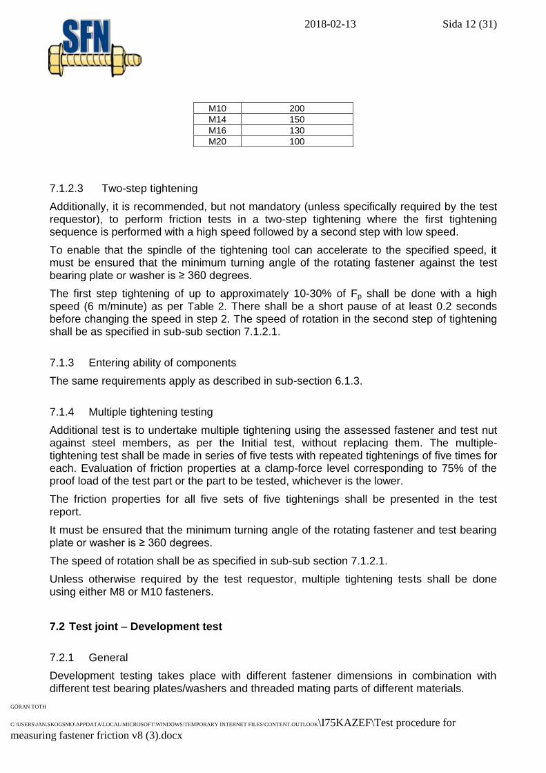
Table 2. High speed of rotation for different fastener sizes.
Bolt size Speed of rotation [rpm]
M8 250
2018-02-13 Sida 12 (31)
GÖRAN TOTH
C:\USERS\JAN.SKOGSMO\APPDATA\LOCAL\MICROSOFT\WINDOWS\TEMPORARY INTERNET FILES\CONTENT.OUTLOOK\I75KAZEF\Test procedure for
measuring fastener friction v8 (3).docx
M10 200
M14 150
M16 130
M20 100
7.1.2.3 Two-step tightening
Additionally, it is recommended, but not mandatory (unless specifically required by the test requestor), to perform friction tests in a two-step tightening where the first tightening sequence is performed with a high speed followed by a second step with low speed.
To enable that the spindle of the tightening tool can accelerate to the specified speed, it must be ensured that the minimum turning angle of the rotating fastener against the test bearing plate or washer is ≥ 360 degrees.
The first step tightening of up to approximately 10-30% of Fp shall be done with a high speed (6 m/minute) as per Table 2. There shall be a short pause of at least 0.2 seconds before changing the speed in step 2. The speed of rotation in the second step of tightening shall be as specified in sub-sub section 7.1.2.1.
7.1.3 Entering ability of components
The same requirements apply as described in sub-section 6.1.3.
7.1.4 Multiple tightening testing
Additional test is to undertake multiple tightening using the assessed fastener and test nut against steel members, as per the Initial test, without replacing them. The multiple-tightening test shall be made in series of five tests with repeated tightenings of five times for each. Evaluation of friction properties at a clamp-force level corresponding to 75% of the proof load of the test part or the part to be tested, whichever is the lower.
The friction properties for all five sets of five tightenings shall be presented in the test report.
It must be ensured that the minimum turning angle of the rotating fastener and test bearing plate or washer is ≥ 360 degrees.
The speed of rotation shall be as specified in sub-sub section 7.1.2.1.
Unless otherwise required by the test requestor, multiple tightening tests shall be done using either M8 or M10 fasteners.
7.2 Test joint – Development test
7.2.1 General
Development testing takes place with different fastener dimensions in combination with different test bearing plates/washers and threaded mating parts of different materials.
2018-02-13 Sida 13 (31)
GÖRAN TOTH
C:\USERS\JAN.SKOGSMO\APPDATA\LOCAL\MICROSOFT\WINDOWS\TEMPORARY INTERNET FILES\CONTENT.OUTLOOK\I75KAZEF\Test procedure for
measuring fastener friction v8 (3).docx
A test joint consists of a test device/fixture and a transducer for clamp force measurement. In this fixture, a test fastener and a test bearing plate/washer are installed, see Figure 6. Test parts are mating threaded fasteners for the parts to be tested. For testing bolts, screws or nuts under standard conditions, specified test parts (test washers, test-bearing plates, test nuts, test screws) shall be used.
In case the test equipment does not correspond to the tabled exterior measurements on the ruler and/or test bearing plate (washer), deviations may be accepted. These deviations shall be noted in the test report.
All components included in the tests shall be free from corrosion, dirt, grease and oil as well as both external and internal threads shall be free of burrs and impurities that can affect the tightening torque and the friction. For cleaning methods, see chapter 5.
In all cases, it shall be ensured that the internal threads, i.e. in the nut or tapped member, shall have a strength at least corresponding to that of the tested screw.
Clamp length in test joint shall be such that two to seven thread pitches extend outside the nut/threaded ruler, when the screw lies against the test bearing plate.
The screw’s free length of thread shall be such that at least two full threads are within the grip after the nut is seated.
7.2.2 Tested fastener
Development testing is undertaken with fasteners of small and large fastener sizes. The fastener sizes are M8 or M10 and M14, M16 or M20*), respectively. The tests shall be performed with one fastener size from each dimensional group, as a minimum. Fasteners of property class 8.8 for screws and property class 8 for nuts. Also, fasteners of property class 10.9/10 are allowed to be used with appropriate selection of thread-engagement lengths in the internally threaded member, etc.
*) Testing with fastener size M20 is optional since such a large fastener size may require special attention with respect to the coating process, such as rack coating.
7.2.3 Test fastener
Test parts are the mating threaded fasteners for the parts to be tested. For testing bolts, screws or nuts under standard conditions, specified test parts (test washers, test-bearing plates, test nuts, test screws) shall be used. These test parts are specified in section 7.3 to 7.6.
7.2.4 Joint types and choice of material
There are five joint types (in total ten) that are here specified to be studied, depending on if the assessed fastener is a screw or nut. Some of them are mandatory and others are optional in the development tests. The listed joint types include combinations of different materials and surface conditions of the test bearing plate and internally threaded member for cases where the screw or nut is the tested part. The list is tabulated in Table 3 and
2018-02-13 Sida 14 (31)
GÖRAN TOTH
C:\USERS\JAN.SKOGSMO\APPDATA\LOCAL\MICROSOFT\WINDOWS\TEMPORARY INTERNET FILES\CONTENT.OUTLOOK\I75KAZEF\Test procedure for
measuring fastener friction v8 (3).docx
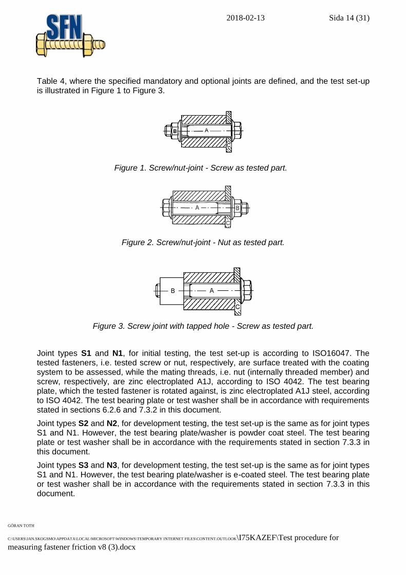
Table 4, where the specified mandatory and optional joints are defined, and the test set-up is illustrated in Figure 1 to Figure 3.
Figure 1. Screw/nut-joint - Screw as tested part.
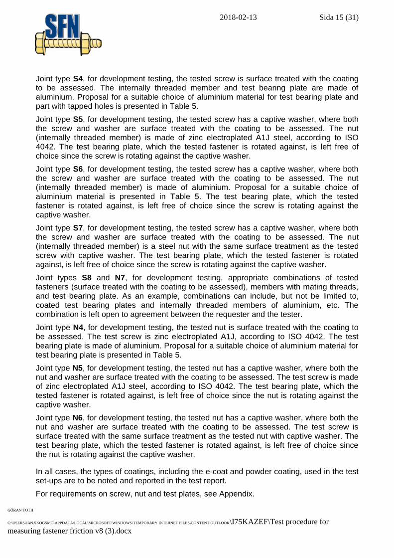
Figure 2. Screw/nut-joint - Nut as tested part.
Figure 3. Screw joint with tapped hole - Screw as tested part.
Joint types S1 and N1, for initial testing, the test set-up is according to ISO16047. The tested fasteners, i.e. tested screw or nut, respectively, are surface treated with the coating system to be assessed, while the mating threads, i.e. nut (internally threaded member) and screw, respectively, are zinc electroplated A1J, according to ISO 4042. The test bearing plate, which the tested fastener is rotated against, is zinc electroplated A1J steel, according to ISO 4042. The test bearing plate or test washer shall be in accordance with requirements stated in sections 6.2.6 and 7.3.2 in this document.
Joint types S2 and N2, for development testing, the test set-up is the same as for joint types S1 and N1. However, the test bearing plate/washer is powder coat steel. The test bearing plate or test washer shall be in accordance with the requirements stated in section 7.3.3 in this document.
Joint types S3 and N3, for development testing, the test set-up is the same as for joint types S1 and N1. However, the test bearing plate/washer is e-coated steel. The test bearing plate or test washer shall be in accordance with the requirements stated in section 7.3.3 in this document.
2018-02-13 Sida 15 (31)
GÖRAN TOTH
C:\USERS\JAN.SKOGSMO\APPDATA\LOCAL\MICROSOFT\WINDOWS\TEMPORARY INTERNET FILES\CONTENT.OUTLOOK\I75KAZEF\Test procedure for
measuring fastener friction v8 (3).docx
Joint type S4, for development testing, the tested screw is surface treated with the coating to be assessed. The internally threaded member and test bearing plate are made of aluminium. Proposal for a suitable choice of aluminium material for test bearing plate and part with tapped holes is presented in Table 5.
Joint type S5, for development testing, the tested screw has a captive washer, where both the screw and washer are surface treated with the coating to be assessed. The nut (internally threaded member) is made of zinc electroplated A1J steel, according to ISO 4042. The test bearing plate, which the tested fastener is rotated against, is left free of choice since the screw is rotating against the captive washer.
Joint type S6, for development testing, the tested screw has a captive washer, where both the screw and washer are surface treated with the coating to be assessed. The nut (internally threaded member) is made of aluminium. Proposal for a suitable choice of aluminium material is presented in Table 5. The test bearing plate, which the tested fastener is rotated against, is left free of choice since the screw is rotating against the captive washer.
Joint type S7, for development testing, the tested screw has a captive washer, where both the screw and washer are surface treated with the coating to be assessed. The nut (internally threaded member) is a steel nut with the same surface treatment as the tested screw with captive washer. The test bearing plate, which the tested fastener is rotated against, is left free of choice since the screw is rotating against the captive washer.
Joint types S8 and N7, for development testing, appropriate combinations of tested fasteners (surface treated with the coating to be assessed), members with mating threads, and test bearing plate. As an example, combinations can include, but not be limited to, coated test bearing plates and internally threaded members of aluminium, etc. The combination is left open to agreement between the requester and the tester.
Joint type N4, for development testing, the tested nut is surface treated with the coating to be assessed. The test screw is zinc electroplated A1J, according to ISO 4042. The test bearing plate is made of aluminium. Proposal for a suitable choice of aluminium material for test bearing plate is presented in Table 5.
Joint type N5, for development testing, the tested nut has a captive washer, where both the nut and washer are surface treated with the coating to be assessed. The test screw is made of zinc electroplated A1J steel, according to ISO 4042. The test bearing plate, which the tested fastener is rotated against, is left free of choice since the nut is rotating against the captive washer.
Joint type N6, for development testing, the tested nut has a captive washer, where both the nut and washer are surface treated with the coating to be assessed. The test screw is surface treated with the same surface treatment as the tested nut with captive washer. The test bearing plate, which the tested fastener is rotated against, is left free of choice since the nut is rotating against the captive washer.
In all cases, the types of coatings, including the e-coat and powder coating, used in the test set-ups are to be noted and reported in the test report.
For requirements on screw, nut and test plates, see Appendix.
2018-02-13 Sida 16 (31)
GÖRAN TOTH
C:\USERS\JAN.SKOGSMO\APPDATA\LOCAL\MICROSOFT\WINDOWS\TEMPORARY INTERNET FILES\CONTENT.OUTLOOK\I75KAZEF\Test procedure for
measuring fastener friction v8 (3).docx
2018-02-13 Sida 17 (31)
GÖRAN TOTH
C:\USERS\JAN.SKOGSMO\APPDATA\LOCAL\MICROSOFT\WINDOWS\TEMPORARY INTERNET FILES\CONTENT.OUTLOOK\I75KAZEF\Test procedure for
measuring fastener friction v8 (3).docx
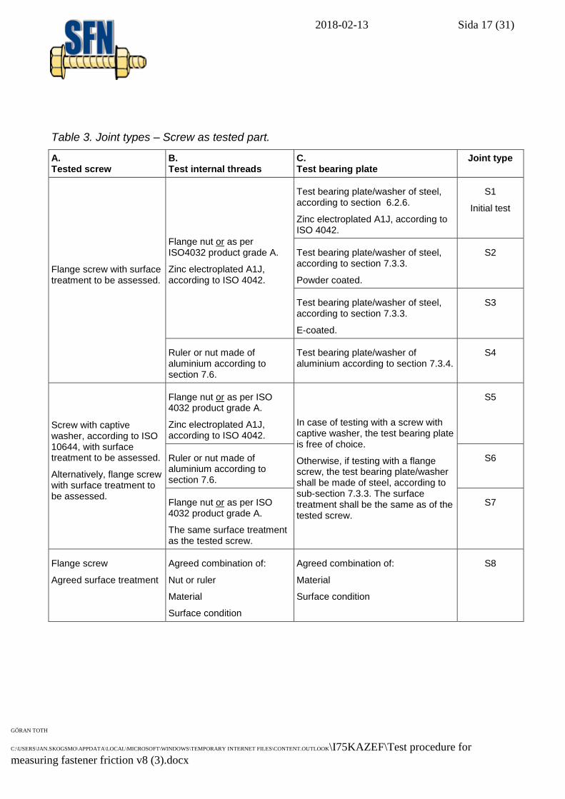
Table 3. Joint types – Screw as tested part.
A. Tested screw
B. Test internal threads
C. Test bearing plate
Joint type
Flange screw with surface treatment to be assessed.
Flange nut or as per ISO4032 product grade A.
Zinc electroplated A1J, according to ISO 4042.
Test bearing plate/washer of steel, according to section 6.2.6.
Zinc electroplated A1J, according to ISO 4042.
S1
Initial test
Test bearing plate/washer of steel, according to section 7.3.3.
Powder coated.
S2
Test bearing plate/washer of steel, according to section 7.3.3.
E-coated.
S3
Ruler or nut made of aluminium according to section 7.6.
Test bearing plate/washer of aluminium according to section 7.3.4.
S4
Screw with captive washer, according to ISO 10644, with surface treatment to be assessed.
Alternatively, flange screw with surface treatment to be assessed.
Flange nut or as per ISO 4032 product grade A.
Zinc electroplated A1J, according to ISO 4042.
In case of testing with a screw with captive washer, the test bearing plate is free of choice.
Otherwise, if testing with a flange screw, the test bearing plate/washer shall be made of steel, according to sub-section 7.3.3. The surface treatment shall be the same as of the tested screw.
S5
Ruler or nut made of aluminium according to section 7.6.
S6
Flange nut or as per ISO 4032 product grade A.
The same surface treatment as the tested screw.
S7
Flange screw
Agreed surface treatment
Agreed combination of:
Nut or ruler
Material
Surface condition
Agreed combination of:
Material
Surface condition
S8
2018-02-13 Sida 18 (31)
GÖRAN TOTH
C:\USERS\JAN.SKOGSMO\APPDATA\LOCAL\MICROSOFT\WINDOWS\TEMPORARY INTERNET FILES\CONTENT.OUTLOOK\I75KAZEF\Test procedure for
measuring fastener friction v8 (3).docx
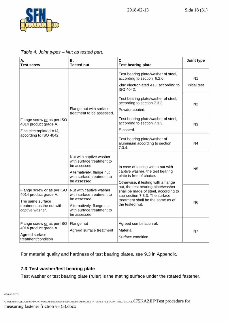
Table 4. Joint types – Nut as tested part.
A. Test screw
B. Tested nut
C. Test bearing plate
Joint type
Flange screw or as per ISO 4014 product grade A.
Zinc electroplated A1J, according to ISO 4042.
Flange nut with surface treatment to be assessed.
Test bearing plate/washer of steel, according to section 6.2.6.
Zinc electroplated A1J, according to ISO 4042.
N1
Initial test
Test bearing plate/washer of steel, according to section 7.3.3.
Powder coated.
N2
Test bearing plate/washer of steel, according to section 7.3.3.
E-coated.
N3
Test bearing plate/washer of aluminium according to section 7.3.4.
N4
Nut with captive washer with surface treatment to be assessed.
Alternatively, flange nut with surface treatment to be assessed.
In case of testing with a nut with captive washer, the test bearing plate is free of choice.
Otherwise, if testing with a flange nut, the test bearing plate/washer shall be made of steel, according to sub-section 7.3.3. The surface treatment shall be the same as of the tested nut.
N5
Flange screw or as per ISO 4014 product grade A.
The same surface treatment as the nut with captive washer.
Nut with captive washer with surface treatment to be assessed.
Alternatively, flange nut with surface treatment to be assessed.
N6
Flange screw or as per ISO 4014 product grade A.
Agreed surface treatment/condition
Flange nut
Agreed surface treatment
Agreed combination of:
Material
Surface condition
N7
For material quality and hardness of test bearing plates, see 9.3 in Appendix.
7.3 Test washer/test bearing plate
Test washer or test bearing plate (ruler) is the mating surface under the rotated fastener.
2018-02-13 Sida 19 (31)
GÖRAN TOTH
C:\USERS\JAN.SKOGSMO\APPDATA\LOCAL\MICROSOFT\WINDOWS\TEMPORARY INTERNET FILES\CONTENT.OUTLOOK\I75KAZEF\Test procedure for
measuring fastener friction v8 (3).docx
7.3.1 General requirements
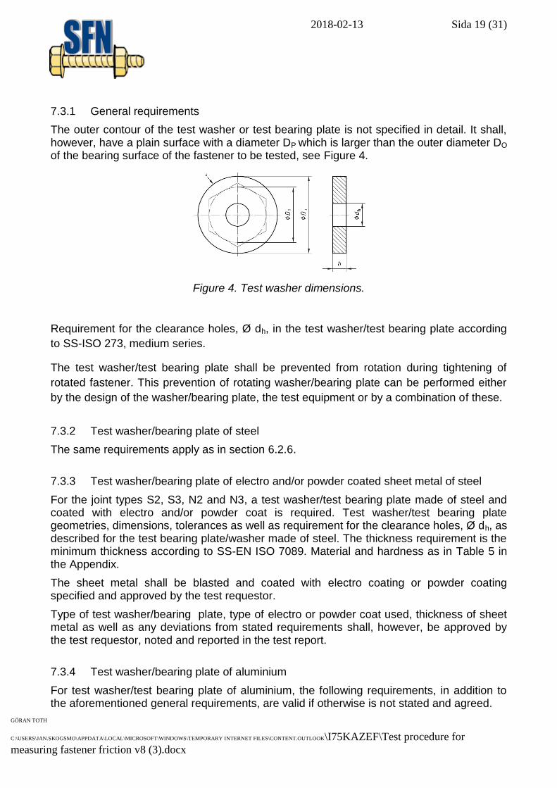
The outer contour of the test washer or test bearing plate is not specified in detail. It shall, however, have a plain surface with a diameter DP which is larger than the outer diameter DO of the bearing surface of the fastener to be tested, see Figure 4.
Figure 4. Test washer dimensions.
Requirement for the clearance holes, Ø dh, in the test washer/test bearing plate according
to SS-ISO 273, medium series.
The test washer/test bearing plate shall be prevented from rotation during tightening of
rotated fastener. This prevention of rotating washer/bearing plate can be performed either
by the design of the washer/bearing plate, the test equipment or by a combination of these.
7.3.2 Test washer/bearing plate of steel
The same requirements apply as in section 6.2.6.
7.3.3 Test washer/bearing plate of electro and/or powder coated sheet metal of steel
For the joint types S2, S3, N2 and N3, a test washer/test bearing plate made of steel and coated with electro and/or powder coat is required. Test washer/test bearing plate geometries, dimensions, tolerances as well as requirement for the clearance holes, Ø dh, as described for the test bearing plate/washer made of steel. The thickness requirement is the minimum thickness according to SS-EN ISO 7089. Material and hardness as in Table 5 in the Appendix.
The sheet metal shall be blasted and coated with electro coating or powder coating specified and approved by the test requestor.
Type of test washer/bearing plate, type of electro or powder coat used, thickness of sheet metal as well as any deviations from stated requirements shall, however, be approved by the test requestor, noted and reported in the test report.
7.3.4 Test washer/bearing plate of aluminium
For test washer/test bearing plate of aluminium, the following requirements, in addition to the aforementioned general requirements, are valid if otherwise is not stated and agreed.
2018-02-13 Sida 20 (31)
GÖRAN TOTH
C:\USERS\JAN.SKOGSMO\APPDATA\LOCAL\MICROSOFT\WINDOWS\TEMPORARY INTERNET FILES\CONTENT.OUTLOOK\I75KAZEF\Test procedure for
measuring fastener friction v8 (3).docx
Surface roughness, hardness and material quality requirements in accordance with Table 6 in the Appendix. Roughness requirement is valid for both sides of washer/bearing plate. Requirements for flatness and parallelism as stated in Figure 7 in the Appendix.
In Table 7 in the Appendix, basic geometries of the test bearing plates (rulers) are presented for testing fastener sizes M8, M10, M14, M16. It must be ensured that the geometry has no negative influence on the test results.
7.3.5 Test washer/bearing plate of other materials
For test washer/test bearing plate of other materials, the general requirements are valid if otherwise is not stated and agreed. Requirements for flatness and parallelism as stated in Figure 7 in the Appendix.
7.4 Screw: Dimensions and geometries
Screw dimensions shall be according to SS-EN 1665 for flange screw. If the screw is NOT the driven fastener in the test joint, a test screw according to SS-EN ISO 4014, product grade A is an alternative. The choice of screw is to be noted and reported in the test report.
Screws with captive washer shall be according to ISO 10644. For screw dimensions not specified in ISO 10644, equivalent type of screw and loose washer (or test bearing plate) may be used, if otherwise is not stated and agreed.
7.5 Nut: Dimensions and geometries
In those cases where the internally threaded member is a nut, the dimensions of the nut shall be according to ISO 4161. If the nut is NOT the driven fastener in the test joint, a nut according to SS-EN ISO 4032, product grade A is an alternative. The choice of nut is to be noted and reported in the test report.
Prior testing, an agreement shall be made on which types of nuts with captive washer shall be used. If no standardised nut with captive washer is available, an equivalent type of nut and loose washer (or test bearing plate) may be used, if otherwise is not stated and agreed.
7.6 Test panels with tapped holes (nut ruler)
Test panels or rulers with tapped holes are in some cases used as an alternative to nuts. Such cases can include, but not be limited to, tapped holes in cast materials, e.g. aluminium.
For aluminium, during the drilling operation methylated spirits shall be used as cooling agent to avoid effect on the friction properties. Cutting fluid shall be avoided.
The outer contour of the test panel or test ruler with tapped holes is not specified in detail. It shall, however, have a thickness which has to be adapted to ensure sufficient thread engagement. The width of the test ruler with tapped holes and distance between holes shall be large enough to avoid influence on the test results. The test panel or test ruler with tapped holes shall have a mark on the plain surface from which the holes are machined.
2018-02-13 Sida 21 (31)
GÖRAN TOTH
C:\USERS\JAN.SKOGSMO\APPDATA\LOCAL\MICROSOFT\WINDOWS\TEMPORARY INTERNET FILES\CONTENT.OUTLOOK\I75KAZEF\Test procedure for
measuring fastener friction v8 (3).docx
The requirements for parallelism are as shown in Figure 8 in Appendix. In Table 6 , hardness requirements and proposed material quality of test nut rulers made of aluminium are given. Deviations from these requirements are to be agreed upon between the test requester and the tester, and the agreement documented in the test report.
In section 9.4 in Appendix, basic geometries of a test ruler with tapped holes are presented for M8, M10, M14, M16 and M20 fastener sizes. It must be ensured that the geometry has no negative influence on the test results.
The type of test panel or test ruler with taped holes, material quality, dimensions, as well as any deviations from the stated requirements shall, however, be approved by the test requestor noted and reported in the test report.
7.7 Test procedure
Either the head of the test screw or the test nut shall be fixed to one side of the test fixture by any means, and the test bearing plate or test washer shall be fixed to the other side of the fixture. The specimen shall be assembled in the fixture, and the screw head or nut – whichever is free to rotate – shall be driven by applying the tightening torque.
When testing screw and washer assemblies or nut and washer assemblies, the washer is to be fixed during the test, if otherwise is not specifically agreed upon. Such agreements shall be documented and reported in the test report.
Testing shall be carried out at an ambient temperature of 18°C – 30°C using a clamp force and torque measuring device in accordance with the section ”Apparatus”.
New, unused parts, including screw, tapped hole (including nut), test bearing plate/washer shall be used for each test sample. Reuse of any of the parts can affect the friction.
The temperature of the test pieces shall be the temperature of the test room.
All parts for testing (screw, tapped hole (including nut), test bearing plate/washer) shall be free of moisture, since that can affect the friction.
The actual parameters, e.g. torque and clamp force, are measured and registered continuously throughout the entire tightening procedure. In order to facilitate dismantling of the joint, the tightening procedure can be interrupted when neither force nor torque increases further or when the desired force has been achieved. Tightening to rupture needs only to occur upon specific tests when the rupture force and rupture moment is sought.
The actual tightening speed as well as the measured results shall be noted in the test record.
7.8 Registration of testing parameters
7.8.1 Points of evaluation
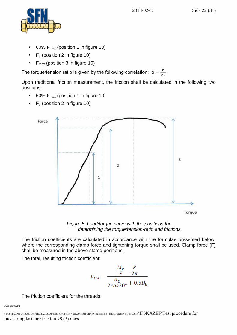
Three positions on the load/torque curve shall be determined when one wishes to study the torque/tension ratio (in kN/Nm) in a screw joint. These positions correspond to:
2018-02-13 Sida 22 (31)
GÖRAN TOTH
C:\USERS\JAN.SKOGSMO\APPDATA\LOCAL\MICROSOFT\WINDOWS\TEMPORARY INTERNET FILES\CONTENT.OUTLOOK\I75KAZEF\Test procedure for
measuring fastener friction v8 (3).docx
• 60% Fmax (position 1 in figure 10)
• Fp (position 2 in figure 10)
• Fmax (position 3 in figure 10)
The torque/tension ratio is given by the following correlation: ϕ
Upon traditional friction measurement, the friction shall be calculated in the following two positions:
• 60% Fmax (position 1 in figure 10)
• Fp (position 2 in figure 10)
Figure 5. Load/torque curve with the positions for determining the torque/tension-ratio and frictions.
The friction coefficients are calculated in accordance with the formulae presented below, where the corresponding clamp force and tightening torque shall be used. Clamp force (F) shall be measured in the above stated positions.
The total, resulting friction coefficient:
The friction coefficient for the threads:
2018-02-13 Sida 23 (31)
GÖRAN TOTH
C:\USERS\JAN.SKOGSMO\APPDATA\LOCAL\MICROSOFT\WINDOWS\TEMPORARY INTERNET FILES\CONTENT.OUTLOOK\I75KAZEF\Test procedure for
measuring fastener friction v8 (3).docx
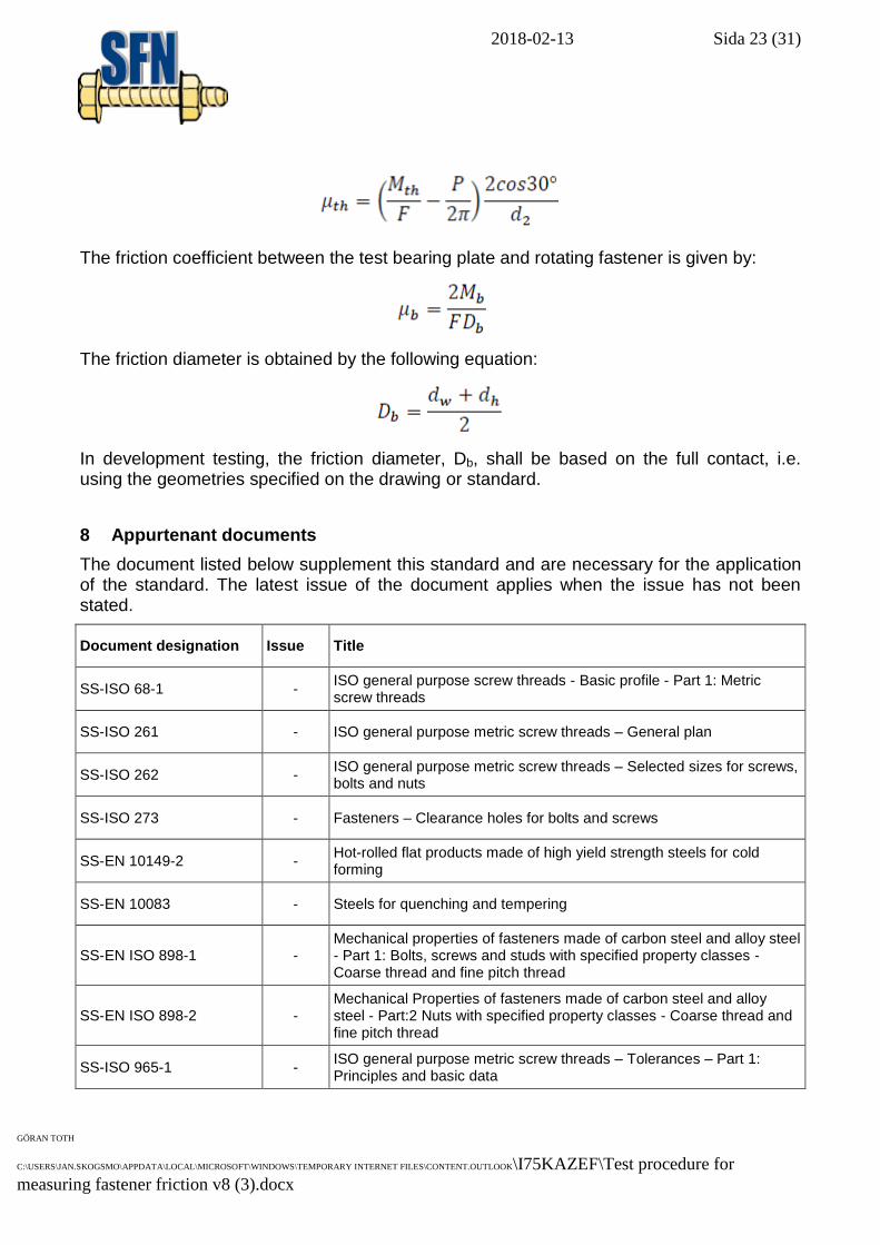
The friction coefficient between the test bearing plate and rotating fastener is given by:
The friction diameter is obtained by the following equation:
In development testing, the friction diameter, Db, shall be based on the full contact, i.e. using the geometries specified on the drawing or standard.
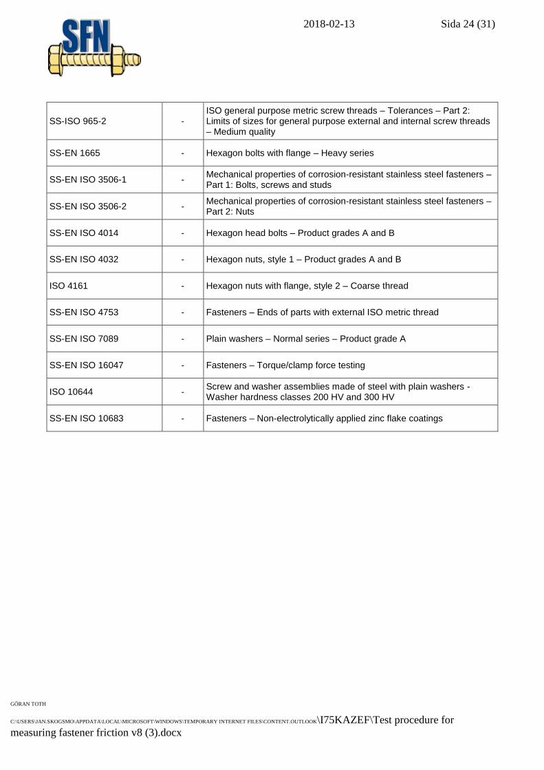
8 Appurtenant documents
The document listed below supplement this standard and are necessary for the application of the standard. The latest issue of the document applies when the issue has not been stated.
Document designation Issue Title
SS-ISO 68-1 - ISO general purpose screw threads - Basic profile - Part 1: Metric screw threads
SS-ISO 261 - ISO general purpose metric screw threads – General plan
SS-ISO 262 - ISO general purpose metric screw threads – Selected sizes for screws, bolts and nuts
SS-ISO 273 - Fasteners – Clearance holes for bolts and screws
SS-EN 10149-2 - Hot-rolled flat products made of high yield strength steels for cold forming
SS-EN 10083 - Steels for quenching and tempering
SS-EN ISO 898-1 - Mechanical properties of fasteners made of carbon steel and alloy steel - Part 1: Bolts, screws and studs with specified property classes - Coarse thread and fine pitch thread
SS-EN ISO 898-2 - Mechanical Properties of fasteners made of carbon steel and alloy steel - Part:2 Nuts with specified property classes - Coarse thread and fine pitch thread
SS-ISO 965-1 - ISO general purpose metric screw threads – Tolerances – Part 1: Principles and basic data
2018-02-13 Sida 24 (31)
GÖRAN TOTH
C:\USERS\JAN.SKOGSMO\APPDATA\LOCAL\MICROSOFT\WINDOWS\TEMPORARY INTERNET FILES\CONTENT.OUTLOOK\I75KAZEF\Test procedure for
measuring fastener friction v8 (3).docx
SS-ISO 965-2 - ISO general purpose metric screw threads – Tolerances – Part 2: Limits of sizes for general purpose external and internal screw threads – Medium quality
SS-EN 1665 - Hexagon bolts with flange – Heavy series
SS-EN ISO 3506-1 - Mechanical properties of corrosion-resistant stainless steel fasteners – Part 1: Bolts, screws and studs
SS-EN ISO 3506-2 - Mechanical properties of corrosion-resistant stainless steel fasteners – Part 2: Nuts
SS-EN ISO 4014 - Hexagon head bolts – Product grades A and B
SS-EN ISO 4032 - Hexagon nuts, style 1 – Product grades A and B
ISO 4161 - Hexagon nuts with flange, style 2 – Coarse thread
SS-EN ISO 4753 - Fasteners – Ends of parts with external ISO metric thread
SS-EN ISO 7089 - Plain washers – Normal series – Product grade A
SS-EN ISO 16047 - Fasteners – Torque/clamp force testing
ISO 10644 - Screw and washer assemblies made of steel with plain washers - Washer hardness classes 200 HV and 300 HV
SS-EN ISO 10683 - Fasteners – Non-electrolytically applied zinc flake coatings
2018-02-13 Sida 25 (31)
GÖRAN TOTH
C:\USERS\JAN.SKOGSMO\APPDATA\LOCAL\MICROSOFT\WINDOWS\TEMPORARY INTERNET FILES\CONTENT.OUTLOOK\I75KAZEF\Test procedure for
measuring fastener friction v8 (3).docx
9 Appendix
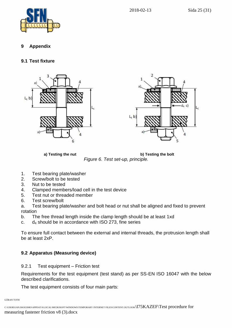
9.1 Test fixture
a) Testing the nut b) Testing the bolt Figure 6. Test set-up, principle.
1. Test bearing plate/washer 2. Screw/bolt to be tested 3. Nut to be tested 4. Clamped members/load cell in the test device 5. Test nut or threaded member 6. Test screw/bolt a. Test bearing plate/washer and bolt head or nut shall be aligned and fixed to prevent rotation b. The free thread length inside the clamp length should be at least 1xd c. d4 should be in accordance with ISO 273, fine series To ensure full contact between the external and internal threads, the protrusion length shall be at least 2xP.
9.2 Apparatus (Measuring device)
9.2.1 Test equipment – Friction test
Requirements for the test equipment (test stand) as per SS-EN ISO 16047 with the below described clarifications.
The test equipment consists of four main parts:
2018-02-13 Sida 26 (31)
GÖRAN TOTH
C:\USERS\JAN.SKOGSMO\APPDATA\LOCAL\MICROSOFT\WINDOWS\TEMPORARY INTERNET FILES\CONTENT.OUTLOOK\I75KAZEF\Test procedure for
measuring fastener friction v8 (3).docx
Tightening tool
Force and torque transducers
Measuring instrument
Test stand (fixture)
For the complete unit, the accuracy shall be such that the total measurement error is maximum ± 5%.
The test equipment shall be provided with an arrangement for continuously measuring the clamp force and the total torque.
The instrument part shall provide a continuous registration of the entire tightening sequence and can be of either an analogue or digital type.
The control drive and measurement equipment used shall be matched to the thread diameter, so that the measurement ranges for the torque and preload forces are properly matched to the recommended working range of the test equipment.
The tightening speed (rotating speed) shall be able to be varied.
The test equipment shall automatically with a constant speed be able to apply a tightening torque and rotation on the driven fastener (nut or screw head) without generating lateral forces on the nut or screw.
All parts in the test joint, except the driven fastener, shall be securely fixed against rotation relative to the test fixture, including the test bearing plate/washer, test fastener, etc.
The test fixture shall be capable of withstanding the combination of clamp force and bearing-surface friction torque without measurable permanent deformation or displacement.
9.2.2 Test equipment – Test of entering ability of components
Test equipment and gauges, according to SS-EN ISO 10683.
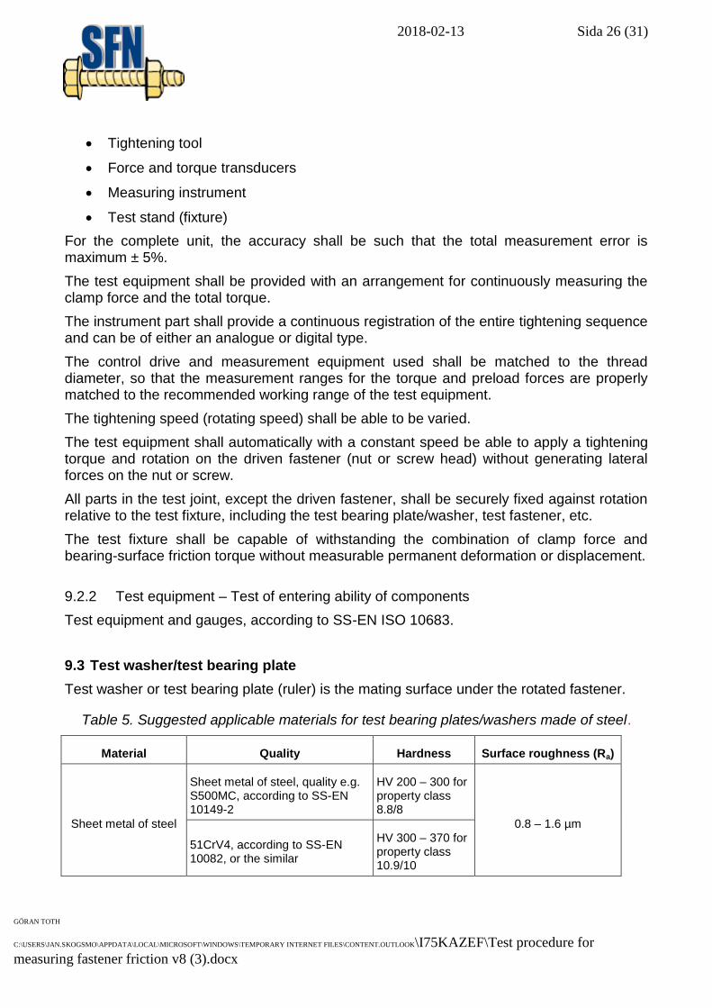
9.3 Test washer/test bearing plate
Test washer or test bearing plate (ruler) is the mating surface under the rotated fastener.
Table 5. Suggested applicable materials for test bearing plates/washers made of steel.
Material Quality Hardness Surface roughness (Ra)
Sheet metal of steel
Sheet metal of steel, quality e.g. S500MC, according to SS-EN 10149-2
HV 200 – 300 for property class 8.8/8
0.8 – 1.6 µm
51CrV4, according to SS-EN 10082, or the similar
HV 300 – 370 for property class 10.9/10
2018-02-13 Sida 27 (31)
GÖRAN TOTH
C:\USERS\JAN.SKOGSMO\APPDATA\LOCAL\MICROSOFT\WINDOWS\TEMPORARY INTERNET FILES\CONTENT.OUTLOOK\I75KAZEF\Test procedure for
measuring fastener friction v8 (3).docx
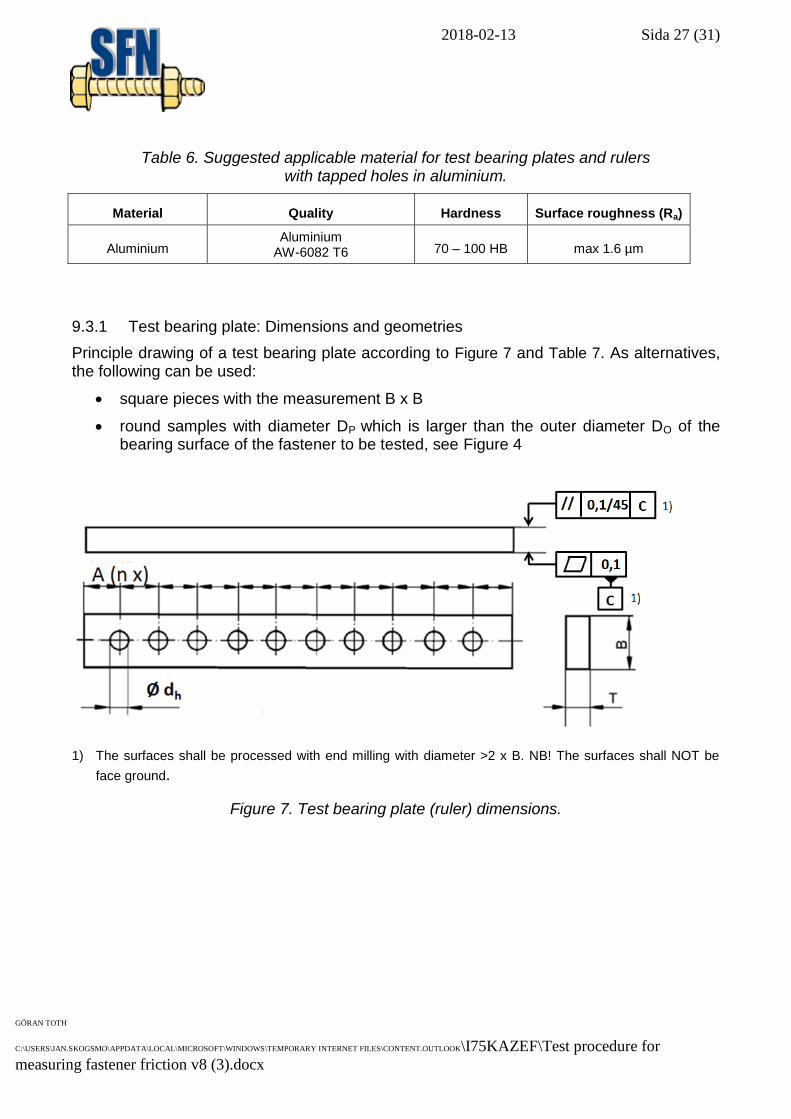
Table 6. Suggested applicable material for test bearing plates and rulers with tapped holes in aluminium.
Material Quality Hardness Surface roughness (Ra)
Aluminium Aluminium
AW-6082 T6 70 – 100 HB max 1.6 µm
9.3.1 Test bearing plate: Dimensions and geometries
Principle drawing of a test bearing plate according to Figure 7 and Table 7. As alternatives, the following can be used:
square pieces with the measurement B x B
round samples with diameter DP which is larger than the outer diameter DO of the bearing surface of the fastener to be tested, see Figure 4
1) The surfaces shall be processed with end milling with diameter >2 x B. NB! The surfaces shall NOT be
face ground.
Figure 7. Test bearing plate (ruler) dimensions.
2018-02-13 Sida 28 (31)
GÖRAN TOTH
C:\USERS\JAN.SKOGSMO\APPDATA\LOCAL\MICROSOFT\WINDOWS\TEMPORARY INTERNET FILES\CONTENT.OUTLOOK\I75KAZEF\Test procedure for
measuring fastener friction v8 (3).docx
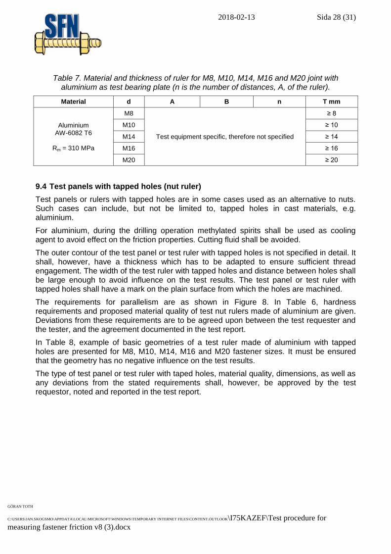
Table 7. Material and thickness of ruler for M8, M10, M14, M16 and M20 joint with aluminium as test bearing plate (n is the number of distances, A, of the ruler).
Material d A B n T mm
Aluminium AW-6082 T6
Rm = 310 MPa
M8
Test equipment specific, therefore not specified
≥ 8
M10 ≥ 10
M14 ≥ 14
M16 ≥ 16
M20 ≥ 20
9.4 Test panels with tapped holes (nut ruler)
Test panels or rulers with tapped holes are in some cases used as an alternative to nuts. Such cases can include, but not be limited to, tapped holes in cast materials, e.g. aluminium.
For aluminium, during the drilling operation methylated spirits shall be used as cooling agent to avoid effect on the friction properties. Cutting fluid shall be avoided.
The outer contour of the test panel or test ruler with tapped holes is not specified in detail. It shall, however, have a thickness which has to be adapted to ensure sufficient thread engagement. The width of the test ruler with tapped holes and distance between holes shall be large enough to avoid influence on the test results. The test panel or test ruler with tapped holes shall have a mark on the plain surface from which the holes are machined.
The requirements for parallelism are as shown in Figure 8. In Table 6, hardness requirements and proposed material quality of test nut rulers made of aluminium are given. Deviations from these requirements are to be agreed upon between the test requester and the tester, and the agreement documented in the test report.
In Table 8, example of basic geometries of a test ruler made of aluminium with tapped holes are presented for M8, M10, M14, M16 and M20 fastener sizes. It must be ensured that the geometry has no negative influence on the test results.
The type of test panel or test ruler with taped holes, material quality, dimensions, as well as any deviations from the stated requirements shall, however, be approved by the test requestor, noted and reported in the test report.
2018-02-13 Sida 29 (31)
GÖRAN TOTH
C:\USERS\JAN.SKOGSMO\APPDATA\LOCAL\MICROSOFT\WINDOWS\TEMPORARY INTERNET FILES\CONTENT.OUTLOOK\I75KAZEF\Test procedure for
measuring fastener friction v8 (3).docx
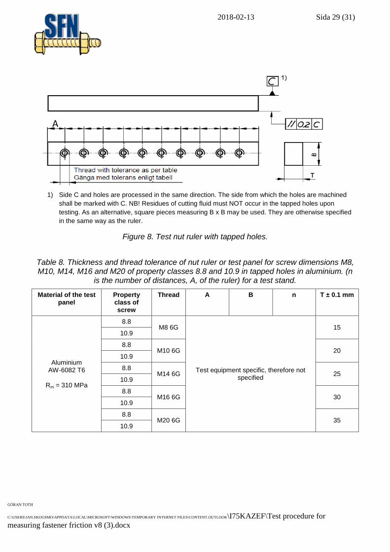
1) Side C and holes are processed in the same direction. The side from which the holes are machined
shall be marked with C. NB! Residues of cutting fluid must NOT occur in the tapped holes upon
testing. As an alternative, square pieces measuring B x B may be used. They are otherwise specified
in the same way as the ruler.
Figure 8. Test nut ruler with tapped holes.
Table 8. Thickness and thread tolerance of nut ruler or test panel for screw dimensions M8, M10, M14, M16 and M20 of property classes 8.8 and 10.9 in tapped holes in aluminium. (n
is the number of distances, A, of the ruler) for a test stand.
Material of the test panel
Property class of screw
Thread A B n T ± 0.1 mm
Aluminium AW-6082 T6
Rm = 310 MPa
8.8 M8 6G
Test equipment specific, therefore not specified
15 10.9
8.8 M10 6G 20
10.9
8.8 M14 6G 25
10.9
8.8 M16 6G 30
10.9
8.8 M20 6G 35
10.9
A (nx)
2018-02-13 Sida 30 (31)
GÖRAN TOTH
C:\USERS\JAN.SKOGSMO\APPDATA\LOCAL\MICROSOFT\WINDOWS\TEMPORARY INTERNET FILES\CONTENT.OUTLOOK\I75KAZEF\Test procedure for
measuring fastener friction v8 (3).docx
9.5 Evaluation and test report
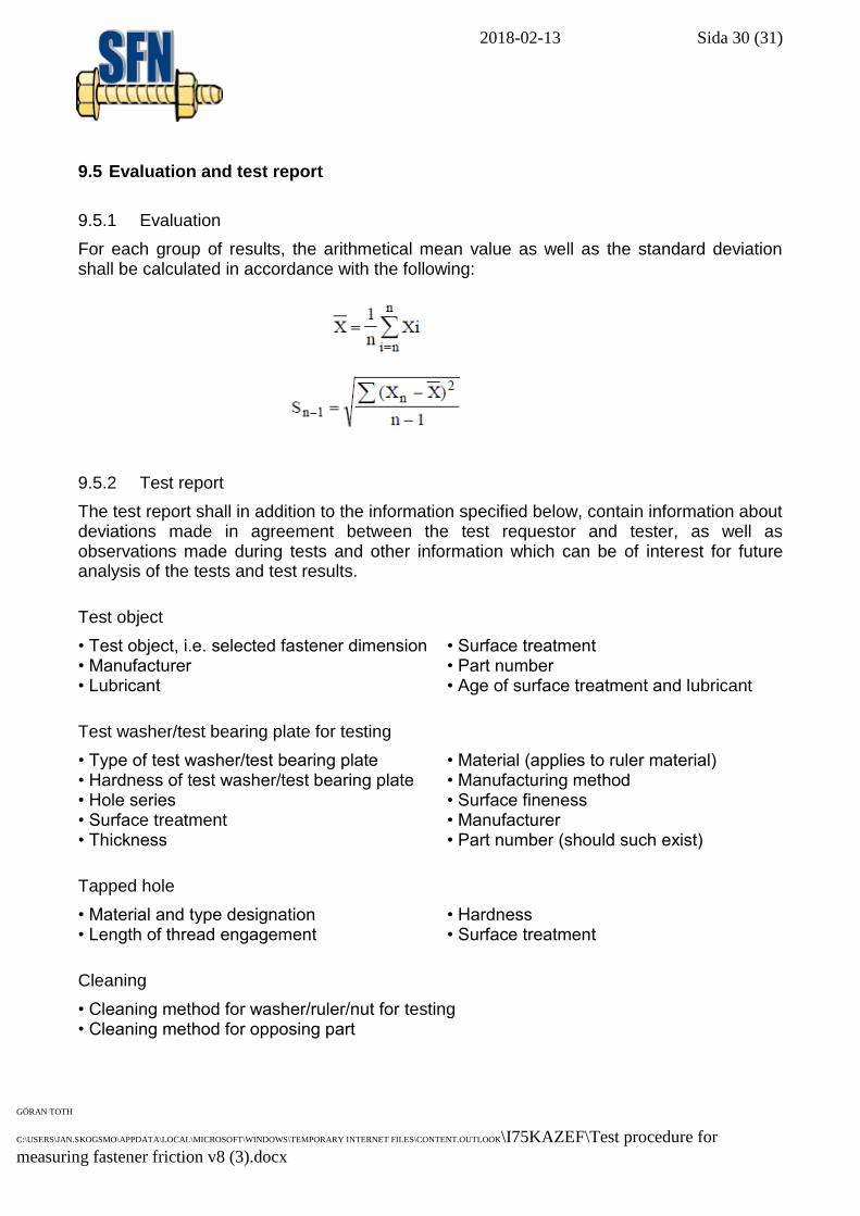
9.5.1 Evaluation
For each group of results, the arithmetical mean value as well as the standard deviation shall be calculated in accordance with the following:
9.5.2 Test report
The test report shall in addition to the information specified below, contain information about deviations made in agreement between the test requestor and tester, as well as observations made during tests and other information which can be of interest for future analysis of the tests and test results.
Test object
• Test object, i.e. selected fastener dimension • Surface treatment • Manufacturer • Part number • Lubricant • Age of surface treatment and lubricant
Test washer/test bearing plate for testing
• Type of test washer/test bearing plate • Material (applies to ruler material) • Hardness of test washer/test bearing plate • Manufacturing method • Hole series • Surface fineness • Surface treatment • Manufacturer • Thickness • Part number (should such exist)
Tapped hole
• Material and type designation • Hardness • Length of thread engagement • Surface treatment
Cleaning
• Cleaning method for washer/ruler/nut for testing • Cleaning method for opposing part
2018-02-13 Sida 31 (31)
GÖRAN TOTH
C:\USERS\JAN.SKOGSMO\APPDATA\LOCAL\MICROSOFT\WINDOWS\TEMPORARY INTERNET FILES\CONTENT.OUTLOOK\I75KAZEF\Test procedure for
measuring fastener friction v8 (3).docx
Test equipment
• Test equipment • Tightening speed
Testing result
• Number of tests • Clamp force • Tightening torque • Torque/tension ratio • Friction coefficients, μtot, μth, μb • Deviation in percent • Arithmetical mean • Standard deviation, Sn-1
• Friction diameter (based on either witness marks in initial testing or full contact in developments testing)