Embed Size (px)
Citation preview

Testing of Full-Scale Two-Story Steel Plate Shear Wall withReduced Beam Section Connections and Composite Floors
Bing Qu, S.M.ASCE1; Michel Bruneau, M.ASCE2; Chih-Han Lin3; and Keh-Chyuan Tsai4
Abstract: A two-phase experimental program was generated on a full-scale two-story steel plate shear wall with reduced beam sectionconnections and composite floors, to experimentally address the replaceability of infill panels following an earthquake and the seismicbehavior of the intermediate beam. In Phase I, the specimen was pseudodynamically tested, subjected to three ground motions ofprogressively decreasing intensity. The buckled panels were replaced by new panels prior to submitting the specimen to a subsequentpseudodynamic test and cyclic test to failure in Phase II. It is shown that the repaired specimen can survive and dissipate significantamounts of hysteretic energy in a subsequent earthquake without severe damage to the boundary frame or overall strength degradation. Itis also found that the specimen had exceptional redundancy and exhibited stable force-displacement behavior up to the story drifts of 5.2and 5.0% at the first and second story, respectively. Experimental results from pseudodynamic and cyclic tests are compared to seismicperformance predictions obtained from a dual strip model using tension only strips and from a monotonic pushover analysis using athree-dimensional finite-element model, respectively, and good agreement is observed.
DOI: 10.1061/�ASCE�0733-9445�2008�134:3�364�
CE Database subject headings: Shear walls; Steel plates; Replacement; Cyclic tests; Seismic design; Pseudodynamic method.
Introduction
A steel plate shear wall �SPSW� consists of infill steel panelssurrounded by boundary beams and columns. These panels areallowed to buckle in shear and subsequently form a diagonal ten-sion field. SPSWs are progressively being used as the primarylateral force resisting systems in buildings �Sabelli and Bruneau2006�. Past monotonic, cyclic, and shaking table tests on SPSWin the United States, Canada, Japan, Taiwan, and other countrieshave shown that this type of structural system can exhibit highinitial stiffness, behave in a ductile manner, and dissipate signifi-cant amounts of hysteretic energy, which make it a suitable optionfor the design of new buildings as well as for the retrofit ofexisting constructions �extensive literature reviews are available
1Ph.D. Candidate, Dept. of Civil, Structural and EnvironmentalEngineering, 206 Ketter Hall, Univ. at Buffalo, Buffalo, NY 14260�corresponding author�. E-mail: [email protected]
2Director, Multidisciplinary Center for Earthquake EngineeringResearch; and, Professor, Dept. of Civil, Structural and EnvironmentalEngineering, Univ. at Buffalo, Buffalo, NY 14260. E-mail: [email protected]
3Assistant Research Fellow, National Center for Research onEarthquake Engineering, 200, Sec. 3, Xinhai Rd., Taipei 106, Taiwan.E-mail: [email protected]
4Director, National Center for Research on Earthquake Engineeringand Professor, Dept. of Civil Engineering, National Taiwan Univ., 200,Sec. 3, Xinhai Rd., Taipei 106, Taiwan. E-mail: [email protected]
Note. Associate Editor: Scott A. Civjan. Discussion open until August1, 2008. Separate discussions must be submitted for individual papers. Toextend the closing date by one month, a written request must be filed withthe ASCE Managing Editor. The manuscript for this paper was submittedfor review and possible publication on January 18, 2007; approved onJuly 5, 2007. This paper is part of the Journal of Structural Engineer-ing, Vol. 134, No. 3, March 1, 2008. ©ASCE, ISSN 0733-9445/2008/3-
364–373/$25.00.364 / JOURNAL OF STRUCTURAL ENGINEERING © ASCE / MARCH 2008
in Sabelli and Bruneau 2006; Berman and Bruneau 2003a, toname a few�. Analytical research on SPSW has also validateduseful models for the design and analysis of this lateral load re-sisting system �Thorburn et al. 1983; Elgaaly et al. 1993; Driveret al. 1997; Berman and Bruneau 2003b�. Recent design proce-dures for SPSW are provided by the CSA “Limit states design ofsteel structures” �CSA 2003� and the AISC Seismic Provision forStructural Steel Buildings �AISC 2005�. Innovative SPSW de-signs have also been proposed and experimentally validated toexpand the range of applicability of SPSW �Berman and Bruneau2003a,b; Vian and Bruneau 2005�.
However, some impediments still exist that may limit thewidespread acceptance of this structural system. For example, noresearch has directly addressed the replaceability of infill steelpanels following an earthquake, and there remain uncertaintiesregarding the seismic behavior of intermediate beams in SPSW�intermediate beams are those to which steel plates are weldedabove and below, by opposition to top and bottom beams thathave steel plates only below or above, respectively�. The latterproblem was analytically addressed by Lopez Garcia and Bruneau�2006� using simple models, but experimental investigations onthe behavior of intermediate beams, particularly for beams havingreduced beam section �RBS� connections and composite concreteslabs, can provide much needed information on the behavior ofthis structural system and how to best design the intermediatebeams.
To address the above issues with regard to SPSW perfor-mance, a two-phase experimental program was developed to testa two-story SPSW specimen having an intermediate compositebeam with RBS connections. The testing program also investi-gated how to replace a steel panel after a severe earthquake andhow the repaired SPSW would behave in a second earthquake.This paper summarizes the tests conducted, observed ultimate be-havior, and adequacy of simple models to replicate the global
behavior of the SPSW considered.
Specimen Description Test Setupand Instrumentation
A full-scale two-story one-bay SPSW specimen was designed andfabricated in Taiwan and a two-phase experimental program�Phase I and II tests� was conducted at the laboratory of the Na-tional Center for Research on Earthquake Engineering �NCREE�in Taipei, Taiwan.
The specimen, with equal height and width panels at eachstory, was 8,000 mm high �4,000 mm at each story� and4,000 mm wide, measured between boundary frame member cen-terlines. The infill panels and boundary frame members weresized based on the recommendations provided by Berman andBruneau �2003b�. Beams and columns were of A572 Grade 50steel members. Infill panels were specified to be SS400 steel,which is similar to ASTM A36 steel �Kuan 2005�. H532�314�25�40 columns were used at each story. H446�302�13�21, H350�252�11�19, and H458�306�17�27 beamswere employed at the top, intermediate, and bottom levels, re-spectively. The names of Taiwan designation H shapes �corre-sponding to United States designation W shapes� reflect theirdepth, flange width, as well as web and flange thicknesses. TheRBS connection design procedure of Federal Emergency Man-agement Agency �FEMA� Document, FEMA 350 �FEMA 2000�was used to detail the beam-to-column connections at the top,intermediate, and bottom levels, respectively. This detail was de-signed to ensure all inelastic beam action would occur at theselocations. Composite slabs, having a 3W-0.92t corrugated steeldeck per Taiwan designation equivalent to a 3 in. compositegauge 20 deck �James River Steel 2004�, were designed to be150 mm thick from the top of the composite slab to the bottomflute and 2,480 mm wide at floor levels.
In Phase I tests, the infill panels were 3 and 2 mm thick withmeasured yield strength of 335 and 338 MPa at the first and sec-ond story, respectively. Prior to Phase II tests, the buckled infillpanels were removed using flame cut and replaced by 3.2- and2.3-mm-thick new panels with measured yield strength of 310and 285 MPa at the first and second story, respectively. Measureddifferences are within tolerances for such plates and steel grade.Fish plates with thickness of 6 mm and height of 70 mm wereused along the boundary frame members to connect infill panels.The infill panels of Phase I were welded on one side of the fishplates and the new panels installed as part of Phase II werewelded on the other side �after Phase I panels were cut out�. Thespecimen was not straightened between tests. In the Phase I tests,the infill panels were restrained by horizontal restrainers for thesole purpose of minimizing the amplitude of the out-of-plane dis-placements of the panels that typically develop in SPSW at largeinelastic story drifts. According to the restrainer design procedureproposed by Lin et al. �2006�, rectangular tubes of 125�75�4and 125�75�2.3 were placed at quarter points of the first andsecond story, respectively. The names of Taiwan designation rect-angular tubes �corresponding to United States designation rectan-gular HHS� reflect their depth, width, as well as wall thickness.No restrainers were utilized in Phase II tests. The specimen isshown schematically in Fig. 1. This paper principally focuses onthe Phase II tests as these specimens are more representative ofNorth American practice.
The specimen was mounted on the strong floor. In-plane�north-south� servo controlled hydraulic actuators were mountedbetween the specimen and a reaction wall. Based on the ultimatestrength of the specimen assessed using plastic analysis proce-
dures �Berman and Bruneau 2003b�, three 1,000 kN hydraulicJOURN
actuators were employed to apply earthquake load or cyclic loadon the specimen at each story. Ancillary trusses �as part ofthe floor slab system� were used to transfer in-plane loads tothe specimen at the floor levels. In order to avoid out-of-plane�east-west� displacements of the SPSW at floor levels, two hy-draulic actuators were mounted at each floor level between theedge of the floor �ancillary truss� and a reaction frame. A verticalload of 1,400 kN was applied by a reaction beam at the top ofeach column to simulate gravity load that would be present in theprototype. Each reaction beam transferred the load exerted fromtwo vertical actuators mounted between the reaction beam andanchor rods pinned to the strong floor. The test setup is illustratedin Figs. 2�a and b�.
Instrumentation consisted of strain gauges mounted on theboundary frame. Uniaxial strain gauges were placed at quarterpoints of the story height on the flange of each column. Rosettestrain gauges were placed at 1 /4 and 3 /4 points of the storyheight on the web of each column �one on each side of the web�so that the principal stress could be obtained.
Tiltmeters were placed at various locations on every beam andcolumn to obtain in-plane rotations of these parts. Dial meterswere placed at each column base to monitor the relative displace-ment between the column bases and strong floor resulting frompossible slippage of the specimen on the strong floor under in-plane loading.
Magnetostrictive transducers �Temposonics� were placed at thenorth ends of the intermediate and top beams, respectively, toobtain the story drift histories during the tests.
Based on the preliminary strip model of the SPSW specimen,linearly variable displacement transformers �LVDTs� were placedacross the panels at an angle of 41° from the vertical to obtain thediagonal elongation of the infill panels �12 LVDTs for each story,i.e., six on each side of the infill panel�.
PI gauges were placed at the panel zones of intermediate andbottom beam-to-column connections, respectively, to obtain thedeformation of these parts. A total of 203 channels were used to
Fig. 1. Schematic of specimen
collect experimental data. More information about the instrumen-
AL OF STRUCTURAL ENGINEERING © ASCE / MARCH 2008 / 365
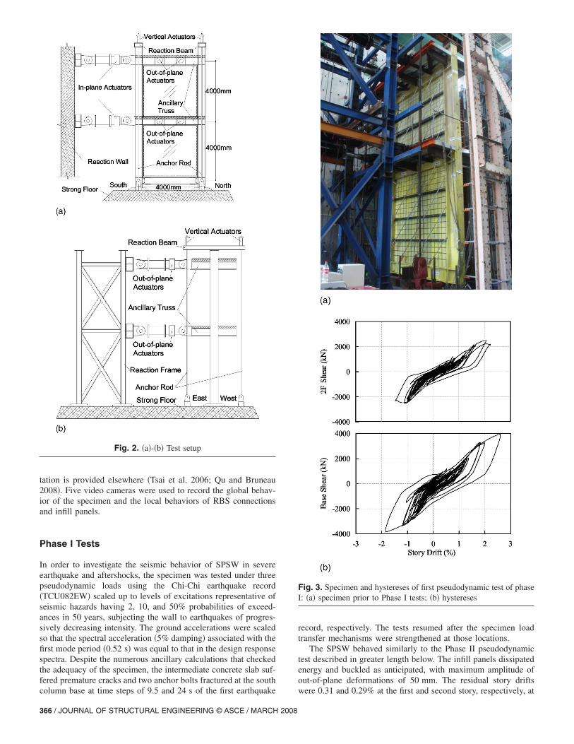
tation is provided elsewhere �Tsai et al. 2006; Qu and Bruneau2008�. Five video cameras were used to record the global behav-ior of the specimen and the local behaviors of RBS connectionsand infill panels.
Phase I Tests
In order to investigate the seismic behavior of SPSW in severeearthquake and aftershocks, the specimen was tested under threepseudodynamic loads using the Chi-Chi earthquake record�TCU082EW� scaled up to levels of excitations representative ofseismic hazards having 2, 10, and 50% probabilities of exceed-ances in 50 years, subjecting the wall to earthquakes of progres-sively decreasing intensity. The ground accelerations were scaledso that the spectral acceleration �5% damping� associated with thefirst mode period �0.52 s� was equal to that in the design responsespectra. Despite the numerous ancillary calculations that checkedthe adequacy of the specimen, the intermediate concrete slab suf-fered premature cracks and two anchor bolts fractured at the south
Fig. 2. �a�-�b� Test setup
column base at time steps of 9.5 and 24 s of the first earthquake
366 / JOURNAL OF STRUCTURAL ENGINEERING © ASCE / MARCH 2008
record, respectively. The tests resumed after the specimen loadtransfer mechanisms were strengthened at those locations.
The SPSW behaved similarly to the Phase II pseudodynamictest described in greater length below. The infill panels dissipatedenergy and buckled as anticipated, with maximum amplitude ofout-of-plane deformations of 50 mm. The residual story drifts
Fig. 3. Specimen and hystereses of first pseudodynamic test of phaseI: �a� specimen prior to Phase I tests; �b� hystereses
were 0.31 and 0.29% at the first and second story, respectively, at

the end of the Phase I tests. No fracture was found in the bound-ary frame, and it was deemed to be in satisfactory condition,allowing for the replacement of infill panels for the subsequentphase of testing. The global responses corresponding to the firstearthquake record as well as the specimen prior to testing aresummarized in Figs. 3�a and b�. Story drifts designated as “�” or“�” refer to loading in the north and south direction �pushingaway from or pulling towards the reaction wall�, respectively.Detailed information about specimen design and results from thePhase I tests are presented elsewhere �Lin et al. 2006, 2007�.
Phase II Pseudodynamic Test
As mentioned in the descriptions of the specimen, the buckledpanels were replaced by new panels before submitting the SPSWspecimen to further testing. It took a crew of three technicians2- 1 /2 days to complete the infill panel replacement.
In order to investigate how the repaired SPSW specimenwould behave in a second earthquake in the first stage of Phase II,the specimen was tested under pseudodynamic loads correspond-ing to the Chi-Chi earthquake record �TCU082EW� scaled to aseismic hazard having a 2% probability of occurrence in 50 years�i.e., equivalent to the first earthquake record considered in thePhase I tests�. This scaled earthquake record had a peak groundacceleration �PGA� of 0.63g and the peak pseudoacceleration�PSA� response of 1.85g at the fundamental period of 0.52 s. Theoriginal ground motion record and the displacement histories atfloor levels are shown in Fig. 4. Note that loud noise was heard asthe infill panels buckled during the test.
The SPSW specimen and hysteretic curves obtained from thePhase II pseudodynamic test, along with the counterpart resultsobtained from Phase I for a similar level of excitation are shownin Figs. 5�a and b�. Observation of the hysteretic curves obtainedfrom Phase II shows that the first story dissipated more hystereticenergy than the second story. The infill panels buckled over bothstories as anticipated, with maximum amplitude of out-of-plane
Fig. 4. Ground motion record and displacement histories
deformations of 250 mm. Both the first and second story exhib-
JOURN
ited stable force-displacement behavior, with some pinching ofthe hysteretic loops as the magnitude of story drifts increased,particularly after the development of a small fracture along thebottom of the shear tab at the north end of the intermediate beamat story drifts of 2.6 and 2.3% at the first and second story, re-spectively. After the pseudodynamic test, the boundary frame was
Fig. 5. Specimen and hystereses: �a� specimen prior to Phase II tests;�b� hystereses of Phase I and Phase II
in good condition �except for the aforementioned damage in the
AL OF STRUCTURAL ENGINEERING © ASCE / MARCH 2008 / 367

shear tab of the intermediate beam�. There were notable plasticdeformations at the column bases and RBS connections at alllevels. Small fractures were found at the panel corners. All weldswithin the SPSW specimen were intact after the test. The de-formed specimen and buckled panels after the Phase II pseudo-dynamic test are shown in Figs. 6�a–c� respectively.
Comparing the hysteretic curves from the Phase I and Phase IItests shown together in Fig. 5�b�, the two specimens are found tobehave similarly under the same strong ground motion except thatthe initial stiffness of the repaired specimen is higher than that ofthe original one. This is because the results shown for the speci-men in Phase I are those obtained after the specimen was repaireddue to the unexpected failures mentioned earlier. Therefore theinfill panels had already experienced some inelastic deformation
Fig. 6. Deformed specimen and buckled panels in Phase II
before these unexpected failures occurred.
368 / JOURNAL OF STRUCTURAL ENGINEERING © ASCE / MARCH 2008
Analytical Modeling of Phase II PseudodynamicTest
To check the adequacy of the strip model to predict the nonlinearbehavior of SPSW under the Phase II pseudodynamic load, adual strip model using tension-only strips was developed usingthe commercially available finite-element software packageABAQUS/Standard. Thirty strips �15 strips in each direction�were used at each story as shown in Fig. 7�a�. The boundaryframe was fixed at column bases to replicate the test conditions.Boundary conditions preventing out-of-plane displacements wereimposed at floor levels. Gravity loads were first applied at the topof the columns. Then the displacement histories obtained from the
dynamic test: �a� specimen; �b� 1F panel; and �c� 2F panel
pseudotest were used as displacement input at floor levels.
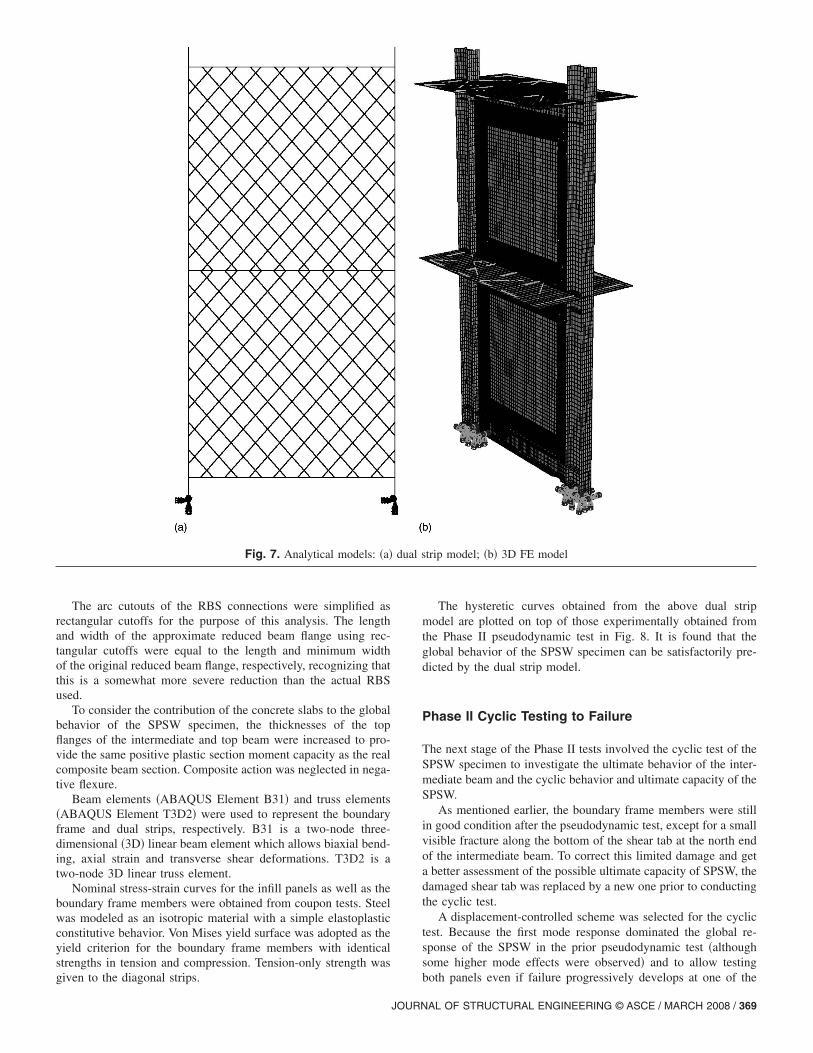
The arc cutouts of the RBS connections were simplified asrectangular cutoffs for the purpose of this analysis. The lengthand width of the approximate reduced beam flange using rec-tangular cutoffs were equal to the length and minimum widthof the original reduced beam flange, respectively, recognizing thatthis is a somewhat more severe reduction than the actual RBSused.
To consider the contribution of the concrete slabs to the globalbehavior of the SPSW specimen, the thicknesses of the topflanges of the intermediate and top beam were increased to pro-vide the same positive plastic section moment capacity as the realcomposite beam section. Composite action was neglected in nega-tive flexure.
Beam elements �ABAQUS Element B31� and truss elements�ABAQUS Element T3D2� were used to represent the boundaryframe and dual strips, respectively. B31 is a two-node three-dimensional �3D� linear beam element which allows biaxial bend-ing, axial strain and transverse shear deformations. T3D2 is atwo-node 3D linear truss element.
Nominal stress-strain curves for the infill panels as well as theboundary frame members were obtained from coupon tests. Steelwas modeled as an isotropic material with a simple elastoplasticconstitutive behavior. Von Mises yield surface was adopted as theyield criterion for the boundary frame members with identicalstrengths in tension and compression. Tension-only strength was
Fig. 7. Analytical models: �a�
given to the diagonal strips.
JOURN
The hysteretic curves obtained from the above dual stripmodel are plotted on top of those experimentally obtained fromthe Phase II pseudodynamic test in Fig. 8. It is found that theglobal behavior of the SPSW specimen can be satisfactorily pre-dicted by the dual strip model.
Phase II Cyclic Testing to Failure
The next stage of the Phase II tests involved the cyclic test of theSPSW specimen to investigate the ultimate behavior of the inter-mediate beam and the cyclic behavior and ultimate capacity of theSPSW.
As mentioned earlier, the boundary frame members were stillin good condition after the pseudodynamic test, except for a smallvisible fracture along the bottom of the shear tab at the north endof the intermediate beam. To correct this limited damage and geta better assessment of the possible ultimate capacity of SPSW, thedamaged shear tab was replaced by a new one prior to conductingthe cyclic test.
A displacement-controlled scheme was selected for the cyclictest. Because the first mode response dominated the global re-sponse of the SPSW in the prior pseudodynamic test �althoughsome higher mode effects were observed� and to allow testing
trip model; �b� 3D FE model
dual sboth panels even if failure progressively develops at one of the
AL OF STRUCTURAL ENGINEERING © ASCE / MARCH 2008 / 369

two stories, a displacement constraint was exerted to keep thein-plane actuators displacing in a ratio corresponding to a firstmode of response throughout the entire test. Table 1 shows thestory drift history of the first and second story, respectively. Sincethe specimen was pulled �to the south� to the maximum actuatorstroke when peak story drifts reached −3.2 and −3.0% at the firstand second story, respectively, the applied displacement historybecame unsymmetrical beyond that point, in that the peak storydrifts due to loading toward the south were kept at −3.2 and−3.0% at the first and second story, respectively, in all subsequentcycles while increasing displacements were still applied in theother direction.
The hysteretic curves resulting from the Phase II cyclic test,along with the results of a monotonic pushover analysis describedin detail in the next section, are shown in Fig. 9. Comparing thehysteretic curves in Fig. 9 to those in Fig. 5�b�, it is observed thatthe initial stiffness of the SPSW specimen in the cyclic test wassmaller than that in pseudodynamic test. Because the previous
Fig. 8. Hystereses from strip model and Phase II pseudodynamic test
Table 1. Cyclic Story Drift Histories
Displacementstep
Numberof cycles
Cumulativenumber
of cycles
1 2 2
2 2 4
3 2 6
4 2 8
5 2 10
6 2 12
7 2 14
8 0.25 14.25a
Not applicable.370 / JOURNAL OF STRUCTURAL ENGINEERING © ASCE / MARCH 2008
pseudodynamic test stretched the infill panels up to specimenstory drifts of 2.6 and 2.3% at the first and second story, respec-tively, the hysteretic loops exhibited pinching up to those storydrifts. Hysteretic loops were then full until story drifts of 2.8 and2.6% at the first and second story, respectively, in Cycle 7, whencomplete fracture occurred along the shear tab at the north end ofthe intermediate beam. This unexpected failure resulted in storyshear reductions of 76 and 83 kN at the first and second story,respectively, mainly because the test was being conducted underdisplacement control rather than force control. A similar fracturedeveloped along the shear tab at the south end of the intermediatebeam when the specimen was pulled towards the reaction wall inthis cycle.
Rupture of the shear tabs triggered fracture of the bottomflange at the north end of the intermediate beam. At story drifts of3.3 and 3.1% at the first and second story, respectively, in Cycle9, the bottom flange at the north end of the intermediate beam
1F 2F
itiveift�
Negativedrift�%�
Positivedrift�%�
Negativedrift�%�
.2 −1.2 1.0 −1.0
.4 −2.4 2.0 −2.0
.0 −3.0 2.5 −2.5
.2 −3.2 3.0 −3.0
.7 −3.2 4.5 −3.5
.3 −3.2 4.0 −3.0
.8 −3.2 4.5 −3.0
.2 —a 5.0 —a
Fig. 9. Monotonic pushover curves and hystereses of Phase II cyclictest
Posdr�%
1
2
3
3
3
4
4
5

fractured as shown in Fig. 10. However, no fractures developed inthe reduced beam flange regions of the intermediate beam. Thewelds connecting the infill panels to the fish plates around thenorth end of the intermediate beam also fractured over a substan-tial length to a more severe extent after the specimen experiencedstory drifts of 5.2 and 5.0% at the first and second story, respec-tively, as shown in Fig. 11. These events significantly changed theload path within the system. However, the SPSW specimen wasstill able to exhibit stable force-displacement behavior as evi-denced by the hysteretic curves shown in Fig. 9, which demon-
Fig. 10. Ruptures at north end of intermediate beam
Fig. 11. Fractures of welds connecting infill panels to fish plates
JOURN
strates the redundancy of this kind of structural system. It is un-clear at this time how much of this redundancy is attributable tothe composite floor and ancillary truss, or the panels and bound-ary frame.
The cyclic test ended at story drifts of 5.2 and 5.0% at the firstand second story, respectively, when sudden failure occurred inthe load transfer mechanism, i.e., when a fatal longitudinal crackdeveloped along the top concrete slab of the specimen, as shownin Fig. 12.
Analytical Modeling of Phase II Cyclic Test
To further assess the global behavior of the SPSW specimen, a 3Dfinite-element �FE� model as shown in Fig. 7�b� was developed inABAQUS/Standard to simulate the responses of the specimensubjected to the Phase II cyclic test. Vian and Bruneau �2005�demonstrated that although the entire cyclic response of SPSWcan be replicated using such finite-element models, the monotonicresponse obtained from a pushover analysis using such a modelcan adequately capture the global behavior of a SPSW at the peakstory drifts of a cyclic test—hence only monotonic analysis wasconducted here.
Shell elements �ABAQUS Element S4R� were employed forall structural subassemblages. S4R is a four-node, quadrilateralshell element with reduced integration and a large-strain formu-lation. A total of 30,553 elements were used for this model. Theboundary frame was fixed at column bases. Boundary conditionspreventing out-of-plane displacements were used along the inter-mediate and top concrete slab, respectively. Gravity loads wereapplied at the top of the columns prior to the in-plane loading.Lateral in-plane displacements were applied at the floor levels inproportion to the same ratio used in the test.
Nominal stress-strain curves for all steel structural subassem-blages were obtained from the coupon test. Steel was modeled asan isotropic material with a simple elastoplastic constitutive be-havior. Von Mises yield surface was selected as the yield crite-rion. In this case, the actual concrete slab was modeled using anunconfined concrete model and the compressive strength mea-sured from cylinder tests.
Linear eigenvalue buckling analysis was performed prior tothe monotonic pushover analysis to introduce initial imperfections
Fig. 12. Crack at top slab
in the panel, and ensure reliable modeling of their buckling. The
AL OF STRUCTURAL ENGINEERING © ASCE / MARCH 2008 / 371
global structural response from this finite-element simulation wascompared with the experimental results from the cyclic test, asshown in Fig. 9.
It is observed that the story shears from the FE analysis aregreater than those obtained from the cyclic test prior to 2.6 and2.3% story drifts at the first and second story, respectively. This isprincipally because the specimen was loaded into the inelasticrange in the prior Phase II pseudodynamic test, resulting in thepartial absence of tension field in the infill panel at low story driftlevels. However, the story shears obtained from FE analysis fitwell those obtained from the cyclic test at story drifts exceedingthe maximum story drifts of 2.6 and 2.3% at the first and secondstory, respectively, reached in the Phase II pseudodynamic test.After story drifts of 3 and 2.5% at the first and second story,respectively, the story shears from cyclic tests are smaller thanthose from FE analysis due to the ruptures in the intermediatebeam and failures of the welds connecting infill panels to fishplates.
Conclusions
A full-scale two-story SPSW specimen with RBS connections andcomposite floors was designed and subjected to pseudodynamicand cyclic testing, to experimentally address the replaceability ofinfill panels following an earthquake, as well as the behavior ofthe repaired SPSW in a subsequent earthquake and the seismicperformance of the intermediate beam.
The pseudodynamic tests show that a SPSW repaired by re-placing the infill panels buckled in a prior earthquake by newones can be a viable option to provide adequate resistance tothe lateral loads imparted on this structure during new seismicexcitations �note that possible undesirable aesthetic issues re-lated to residual story drifts from the first earthquake prior torepair are beyond the scope of this work�. The repaired SPSWbehaved quite similarly to the original one. Testing showedthat the repaired SPSW can survive and dissipate a similaramount of energy in the subsequent earthquake without severedamage to the boundary frame and without overall strengthdegradation.
Results from the cyclic test allow us to investigate the ultimatedisplacement capacity of the SPSW specimen. Although the hys-teretic curves were pinched at the low story drift levels due to theinelastic deformations that the infill panels experienced during thepseudodynamic test, and even though the strength of the SPSWdropped as the ends of the intermediate beam fractured, theSPSW structure exhibited stable force-displacement behavior andprovided a significant energy dissipation capacity, exhibiting sub-stantial redundancy.
The adequacy of the dual strip model using tension-only stripswas found accurate to predict the nonlinear behavior of SPSWunder earthquake load, as demonstrated by comparison with theexperimental results of the Phase II pseudodynamic test. The ul-timate lateral in-plane load capacity of SPSW was shown to beequally well predicted by a monotonic pushover analysis using a3D FE model with shell elements, when comparing with the ex-perimental results from the Phase II cyclic test.
The columns and anchor beams, as well as top and bottomRBS connections performed as intended. However, the inter-mediate beam failed unexpectedly. The ends of the intermediatebeam having RBS connections ultimately developed fracturesin the shear tabs followed by fractures at the end of the bottom
beam flanges. No fractures developed in the reduced beam372 / JOURNAL OF STRUCTURAL ENGINEERING © ASCE / MARCH 2008
flange region. Further investigation is required to clarify the localbehavior of the intermediate beam in SPSW, to develop abetter understanding of how such an intermediate beam should bedesigned.
Acknowledgments
This work was financially supported in part by the Taiwan Na-tional Science Council and the Taiwan National Center forResearch on Earthquake Engineering, and in part by the Earth-quake Engineering Research Centers Program of the US NationalScience Foundation under Award No. ECC-9701471 to the Mul-tidisciplinary Center for Earthquake Engineering Research. Allsponsors are gratefully acknowledged. The writers are also grate-ful to China Steel, who provided the construction materials for thespecimens, and to the technical support at NCREE. Any opinions,findings, conclusions, and recommendations presented in thispaper are those of the writers and do not necessarily reflect theviews of the sponsors.
References
AISC. �2005�. Seismic provisions for structural steel buildings, Chicago.Berman, J. W., and Bruneau, M. �2003a�. “Experimental investigation of
light-gauge steel plate shear walls for the seismic retrofit of build-ings.” Technical Rep. No. MCEER-03-0001, Multidisciplinary Centerfor Earthquake Engineering Research, Buffalo, N.Y.
Berman, J. W., and Bruneau, M. �2003b�. “Plastic analysis and design ofsteel plate shear walls.” J. Struct. Eng., 129�11�, 1448–1456.
Canadian Standards Association �CSA�. �2003�. “Limit states design ofsteel structures.” CAN/CSA S16-01, Willowdale, Ontario.
Driver, R. G., Kulak, G. L., Kennedy, D. J. L., and Elwi, A. E. �1997�.“Seismic behavior of steel plate shear walls.” Structural EngineeringRep. No. 215, Univ. of Alberta, Edmonton, Alberta, Canada.
Elgaaly, M., Caccese, V., and Du, C. �1993�. “Postbuckling behavior ofsteel-plate shear walls under cyclic loads.” J. Struct. Eng., 119�2�,588–605.
Federal Emergency Management Agency �FEMA�. �2000�. “Recom-mended seismic design criteria for new steel moment-frame build-ings.” Rep. No. FEMA 350 Prepared by the SAC Joint Venture forFEMA, Washington, D.C.
James River Steel Inc. �2004�. “Composite floor decks.” �http://www.jamesriversteel.com/comp3.htm�.
Kuan, M. L. �2005�. “Discussion on ASTM A36 and CNS SS400.”�http://www.twce.org.tw/info/%A7%DE%AEv%B3%F8/367-3-1.htm� �in Chinese�.
Lin, C. H., Tsai, K. C., Lin, Y. C., Wang, K. J., Hsieh, W. D., Weng, Y. T.,Qu, B., and Bruneau, M. �2006�. “The substructural pseudodynamictests of a full-scale two-story steel plate shear wall.” Proc., 4th Int.Conf. on Earthquake Engineering. Taipei, Taiwan, Paper No. 155.
Lin, C. H., Tsai, K. C., Lin, Y. C., Wang, K. J., Qu, B., and Bruneau, M.�2007�. “Full scale steel plate shear wall: NCREE/MCEER phaseI tests.” Proc., 9th Canadian Conf. on Earthquake Engineering,Ottawa.
Lopez-Garcia, D., and Bruneau, M. �2006�. “Seismic behavior of inter-mediate beams in steel plate shear walls.” Proc., 8th U.S. NationalConf. on Earthquake Engineering, San Francisco, Paper No. 1089.
Qu, B., and Bruneau, M. �2008�. “Seismic behavior and ductile design ofsteel plate shear wall.” Technical Rep. No. MCEER-08-0010, Multi-disciplinary Center for Earthquake Engineering Research, Buffalo,N.Y., in press.
Sabelli, R., and Bruneau, M. �2006�. Steel plate shear walls (AISC designguide), American Institute of Steel Construction, Chicago.
Thorburn, L. J., Kulak, G. L., and Montgomery, C. J. �1983�. “Analysis

of steel plate shear walls.” Structural Engineering Rep. No. 107, Dept.of Civil Engineering, Univ. of Alberta, Edmonton, Alberta, Canada.
Tsai, K. C., Lin, C. H., Lin, Y. C., Hsieh, W. D., and Qu, B. �2006�.“Substructural hybrid tests of a full scale two-story steel plate shear
wall.” Technical Rep. No. NCREE-06-017, National Center for Re-JOURN
search on Earthquake Engineering, Taipei, Taiwan �in Chinese�.Vian, D., and Bruneau, M. �2005�. “Steel plate shear walls for seismic
design and retrofit of building structure.” Technical Rep. No. MCEER-05-0010, Multidisciplinary Center for Earthquake Engineering Re-
search, Buffalo, N.Y.AL OF STRUCTURAL ENGINEERING © ASCE / MARCH 2008 / 373