Embed Size (px)
Citation preview

Testing of Passive Energy Dissipation Systems
Ian D. Aiken, Douglas K. Nims, Andrew S. Whittaker, and James M. Kelly
ABSTRACT
Over the period 1986 to 1991, seven different passive energy dissipation systems were studied in experimental research programs at the Earthquake Engineering Research Center of the University of California at Berkeley. This paper presents an overview of these studies, describing the different types of devices, the results of the shake table experiments, and associated analytical work. Four of the systems studied are friction systems, and of these, three (Sumitomo, Pall, and Friction-Slip) are based on Coulomb friction. The fourth is the Fluor-Daniel Energy Dissipating Restraint, which is a device capable of providing self-centering friction resistance that is proportional to displacement. The three other systems all have different energy dissipation mechanisms: ADAS elements, which utilize the yielding of mild-steel X-plates; viscoelastic shear dampers using a 3M acrylic copolymer as the dissipative element; and Nickel-Titanium alloy shape-memory devices that take advantage of reversible, stress-induced phase changes in the alloy to dissipate energy. The effectiveness of the various systems is evaluated by comparing the response of the test structures without and with the energy dissipators. In some cases, where devices were studied using the same test structure, they are compared directly. All of the systems investigated exhibited characteristics beneficial to improved structural response to earthquake loading.
INTRODUCTION
Conventional seismic design practice permits the reduction of forces for design below theelastic level on the premise that inelastic action in a suitably designed structure will provide thatstructure with significant energy dissipation potential and enable it to survive a severe earthquakewithout collapse. This inelastic action is typically intended to occur in specially detailed criticalregions of the structure, usually in the beams near or adjacent to the beam-column joints. Inelasticbehavior in these regions, while able to dissipate substantial energy, also often results in significantdamage to the structural member, and although the regions may be well detailed, their hystereticbehavior will degrade with repeated inelastic cycling. The interstory drifts required to achievesignificant hysteretic energy dissipation in critical regions are generally large and usually result insubstantial damage to non-structural elements such as in-fill walls, partitions, doorways, andceilings.
As a response to the shortcomings inherent in the philosophy of conventional seismic design,a number of innovative approaches have been developed. One of these approaches involves addingenergy absorbers to a structure. The aim of including energy absorbers in a structure for earthquakeresistance is to concentrate hysteretic behavior in specially designed and detailed regions of the
(IDA, ASW, and JMK) EERC, University of California at Berkeley, Berkeley, CA 94720(DKN) Department of Civil Engineering, University of Toledo, Toledo, OH 43606
EARTHQUAKE SPECTRA, VOL. 9, NO. 3, EARTHQUAKE ENGINEERING RESEARCH INSTITUTE CALIFORNIA, AUGUST (1993)

structure and to avoid inelastic behavior in primary gravity load- resisting structural elements(except perhaps under the most severe conditions).
Numerous different types of energy-absorbing devices have been proposed for this purpose.Devices based on the plastic deformation of mild steel were developed and extensively tested anumber of years ago (Kelly, 1972). Friction devices of several types have been the subject of anumber of research programs, and there are now a number of building applications. The Pall-typefriction damper has been used in three buildings in Canada, in two new buildings, and in the retrofitof a school building damaged in the Saugenay earthquake of 1989 (Pall, 1987 and 1991, Vezina,1992). By the middle of 1991, Sumitomo-type friction dampers had been incorporated in 31- and22-story buildings, both in Japan. Lead extrusion dampers were used in a recently completed 17-story building, and also in an 8-story building, both in Japan. The first U.S. application of ADASelements for the seismic retrofitting of a building was completed in San Francisco in early 1992(Fierro, 1993). Viscoelastic dampers have been used in several tall buildings for wind vibrationcontrol. The dampers use a highly dissipative polymeric material which has well-defined materialproperties and behavioral characteristics (Mahmoodi, 1969). The most notable applications are thetwin 110-story towers of the World Trade Center in New York City, where dampers have beeninstalled for 20 years (Mahmoodi, 1987). Several other high-rise buildings in the U.S. also useviscoelastic dampers for wind vibration control (Keel, 1986, Mahmoodi, 1989). In Tokyo, a 24-story building was recently completed with bituminous-rubber viscoelastic dampers, providing thestructure with increased damping to resist earthquake loadings (Yokota, 1992).
The role of a passive energy dissipator is to increase the hysteretic damping in the structure.The basic energy relationship of the structure is represented in the following equation:
where:
= earthquake input energy
= kinetic energy in structure
= strain energy in structure
= viscous damping energy
= hysteretic damping energy
The role of this equation in the design process has been developed by a number of researchers(Uang, 1988, Filiatrault, 1990a). The goal is to increase so that, for a given , the elastic strainenergy in the structure is minimized. This means that the structure will undergo smallerdeformations for a given level of input energy than if it did not include energy dissipators.Alternately, increasing permits to be reduced for a higher level of .
EI EK ES Eξ EH+ + +=
EI
EK
ES
Eξ
EH
EH EI
EH ES EI

I. LARGE-SCALE EARTHQUAKE SIMULATOR STUDIES
1. SUMITOMO FRICTION AND 3M VISCOELASTIC DAMPERS
This section presents a summary of the results of the tests of the Sumitomo friction damperand the 3M viscoelastic shear damper. Both series of tests were performed using the same large-scale 9-story steel frame. More details of the results of these shake table tests are given by Aiken(1990a and 1990b).
DESCRIPTION OF TEST FACILITY AND MODEL STRUCTURE
The experimental program was carried out using the earthquake simulator at the EarthquakeEngineering Research Center of the University of California at Berkeley. The earthquake simulator(or shake table) measures 6.1 m x 6.1 m (20 ft. x 20 ft.) in plan and can support test specimensweighing up to 580 kN (130 kips). Simulated seismic motions can be applied vertically and in onehorizontal direction, with maximum accelerations of 1.0g and 1.5g, respectively.
The basic test structure was a 9-story, moment-resisting steel frame representing a section ofa typical steel building at 1/4-scale. The structure was tested as a moment-resisting frame (MRF),a concentrically-braced frame (CBF), and in friction-damped (FD) and viscoelastically-damped(VD) configurations (Fig. 1). The VE dampers were added to the MRF in single-diagonal bracing(Fig. 2), and the friction dampers were added as part of a modified chevron bracing system (Fig. 3).
Mass-similitude scaling, such that model and prototype accelerations are equal, was used forthe shake table tests. This required that approximately 400 kN (90 kips) of mass be added to themodel in the form of concrete blocks and lead billets. The total test weight of the model was 445kN (100 kips). Response quantities measured during the shake table tests included floor
Fig. 1: Test Configurations of Model Structure

displacements and accelerations, brace axial forces and damper displacements, base shear and baseoverturning moment, and shake table accelerations and displacements.
DESCRIPTION OF DAMPERS
The two types of devices studied were a viscoelastic (VE) shear damper and a sliding frictiondamper. The VE damper comprises two layers of material (Fig. 4), and was introduced in single-diagonal bracing in the test structure (Fig. 5). The VE material used in the dampers is an acryliccopolymer developed by 3M Co. It is one of four types of highly dissipative polymer currentlyavailable from 3M. The VE material behavior is influenced by its shear loss modulus, the shearstorage modulus, and their ratio, the material loss factor (Mahmoodi, 1969). These properties aredependent on frequency, temperature, and deformation strain level, and the general relationship isthe same for all of the materials. Thus, one general relationship can be used to predict the propertiesfor any of the four materials. This is the basis of material property charts developed by themanufacturer.
The friction damper was designed and developed by Sumitomo Metal Industries, Ltd., Japan.It is a cylindrical device with friction pads that slide directly on the inner surface of the steel casingof the device (Fig. 6). The friction devices were attached to the underside of the floor beams andconnected to chevron brace assemblages (Fig. 7). The device was originally developed as a shockabsorber in railway rolling stock. The mechanical characteristics of both types of dampers were
Fig. 2: View of Bottom Three Levels of Model With Viscoelastic Dampers
Fig. 3: View of Bottom Three Levels of Model With Friction Damper

well-known from previous studies, and both have already been used in a number of structural ormechanical engineering applications. This experimental study represented the first system-leveltest of the dampers for severe earthquake loading conditions..
DESIGN OF DAMPING SYSTEMS
Friction Dampers
The size (slip force) of the friction dampers and their layout in the test structure wasdetermined using a nonlinear time-history analysis approach. An initial slip load distribution waschosen based on the results of a previous shake table study of the test structure, utilizing anothertype of friction damper (Aiken, 1988), and a series of analyses were performed for a number ofdifferent earthquake records at various input levels. The final slip load distribution was chosen as
Fig. 4: VE Constrained Layer Shear Damper
Fig. 5: Installation of VE Dampers in Model

that which provided the lowest structural response for all of the inputs. The slip loads varied from11.5 kips at the bottom level to 4.8 kips at the top level of the test structure..
Viscoelastic Dampers
The method used for the design of the VE dampers for the test structure was a simplified first-mode procedure aimed at providing the structure with a specified level of damping (10 percent) ata nominal maximum displacement. This was done using an energy approach. A completedescription of the procedure used is given by Aiken (1990). The VE dampers consisted of two 3”x 5” x 0.15” layers of VE material.
EARTHQUAKE SIMULATOR STUDY
Description of Experiments
The four configurations of the model structure (Fig. 1) were subjected to a number of differentdynamic tests. These were pull-back free vibration, pulse, random noise, and earthquake tests.Fundamental frequencies for the MRF and CBF of 1.95 Hz and 2.95 Hz, respectively, wereidentified. The dynamic characteristics of the VD and FD models were a function of the level andtype of excitation, and were largely a result of whether or not the dampers were activated duringthe motion. From the results of the pulse tests, the fundamental frequencies of the VD (dampers
Fig. 6: Sectional View of Friction Damper Fig. 7: Friction Dampers Installed in Model

activated) and the FD (dampers not activated) models were 2.30 Hz and 2.60 Hz, respectively. Theremaining discussion of results is devoted to those from some of the earthquake tests.
Fourteen different earthquake motions were used in the shake table tests of the MRF, CBF,FD, and VD structures. Results are discussed for some of the results obtained for the followingearthquake ground motions:
(i) El Centro, Imperial Valley, California, May 18, 1940,
(ii) Miyagi-ken-oki, Tohoku University, Sendai, Japan, June 12, 1978,
(iii) Taft, Kern County, California, July 21, 1952,
(iv) Llolleo, Chile, March 3, 1985,
(v) La Union (Guerrero array), Michoacan, Mexico, September 19, 1985.
Results
Hysteresis Behaviors: Typical hysteresis loops for the two types of dampers are shown inFig. 8. The VE dampers exhibit elliptical hysteresis loops typical of materials with velocity-dependent properties. The loops are regular in shape and show stable behavior.
A maximum VE damper shear strain of 208 percent was obtained throughout the VD model tests.Viscoelastic dampers have no threshold or activation force level, and thus they dissipate energy forall levels of earthquake excitation. This contrasts with the behavior of the friction dampers, which,for forces less than the slip force, do not slip and thus do not dissipate energy. The stiffnesscharacteristics of the VE dampers are dependent on a number of factors, notably strain amplitude,frequency, and temperature. The variation of VE damper stiffness with shear strain for all of theMiyagi tests is shown in Fig. 9. Between strains of about 0 and 50 percent, there is a large decreasein stiffness, but for strains in the range of about 50 to 200 percent, the stiffness can be regarded asapproximately constant. This assumption was utilized to determine the “effective” damperstiffnesses for the numerical analyses described below. Temperature increases in the VE materialduring earthquake shaking were small and did not significantly affect the behavior of the VEdampers.
Fig. 8: Typical Damper Hysteresis Loops

The friction dampers exhibited outstanding behavior. Their hysteretic behavior is extremelyregular and repeatable. The devices showed almost no variation in slip load during earthquakemotions, and from previous tests of individual dampers, their force-displacement response wasknown to be basically independent of loading frequency, amplitude, number of loading cycles, andtemperature. In contrast to the VE dampers, the friction dampers are not activated during smallexcitations. Under such circumstances, the FD model behaved more as though it were a CBF.
Because of the variation in VE damper stiffness with strain amplitude, the fundamentalfrequency of the VD structure varied with excitation level from 2.43 Hz down to 2.00 Hz,compared with 1.95 Hz for the MRF. Low-level earthquake tests of the FD model revealed afundamental frequency of 2.67 Hz (compared with 2.95 Hz for the CBF), while for largeexcitations, a variation of 2.47 to 2.35 Hz was observed.
System Comparisons: Shake table response comparisons of the various systems were madewherever possible. For a sequence of El Centro and Miyagi tests, the VD model generally behavedin the same way as the CBF with regard to displacements and in the same way as the MRF withregard to accelerations. The same general trends were also seen for the FD model compared withthe CBF and MRF models. Peak base shears of the FD, VD, and MRF models for a series of Miyagitests are compared in Fig. 10, where the FD and VD shears are seen to be less than that of the MRF.This, coupled with the reduced drifts due to the presence of the dampers, represents a significantoverall improvement in response. A large number of equivalent tests were performed on the MRF,FD, and VD models. From response comparisons for the El Centro, Taft, and Miyagi sequences ofinputs, drifts in both the FD and VD models were reduced by 10 to 60 percent over those of theMRF, while story accelerations were reduced by 25 to 60 percent. In all cases, the FD and VDresponses were reduced from those of the MRF.
Floor response spectra were also used to compare the MRF, FD, and VD models. Twopercent-damped spectra for the third floor of each of the models are presented in Fig. 11 for theMiyagi-400 tests. The damped structures both show significant reductions in spectral acceleration,particularly over the range of 5 to 10 Hz. Above 10 Hz, the VD spectrum is about half that of the
Fig. 9: VE Damper Stiffness vs. Shear Strain for Miyagi Tests

MRF, while the FD spectrum is less than or about the same as that of the MRF. These results, andthose for many other earthquake inputs, indicate that these two types of energy absorbers shouldnot pose problems for internal equipment in structures and in the cases studied actually providedimprovements over the equivalent MRF.
Analyses: The FD model was analyzed using the nonlinear analysis program DRAIN-2D.Good agreement with experimental results was obtained. Fig. 12 shows MRF and CBF analysisresults for the Chile-750 input. In contrast with these results, there was no yielding in the FDstructure under this or any other input used in the test program. The VD model also experiencedno yielding in any of the earthquake tests. The stable hysteretic behavior of the friction devicesmakes them particularly amenable to accurate modeling. A linear elastic analysis approach wasused for the VD model, using the finite element program SAP90. The analyses captured both thedamping and stiffness characteristics of the VE dampers accurately. Very good correlation resultswere obtained (Fig. 13). These analyses permitted the separate effects of damping and stiffness to
Fig. 10: MRF, FD, and VD Peak Base Shear vs. PGA for Miyagi Tests
Fig. 11: MRF, FD, and VD Level 3 Two-Percent Damped Floor Response Spectra, Miyagi-400 Tests

be determined (Fig. 14). Increased damping was found to be the major factor in improving theresponse of the VD model.
SUMMARY
Separate comparisons of the FD and VD systems with the “undamped” MRF and CBFstructures showed that both damped systems behaved similarly to the CBF in terms of story driftsand similarly to the MRF in terms of story accelerations and story shears. The FD and VD systemswere remarkably similar with regard to acceleration and displacement responses for a wideselection of earthquake inputs. Peak base shears of the FD and VD models were similar for a rangeof input levels of the El Centro, Miyagi, and Taft signals. They were approximately the same as,or less than, the MRF maximum base shears. These results were achieved while simultaneouslyreducing the drifts to as little as one-half of those of the MRF.
Floor response spectra showed spectral accelerations of both damped systems to be less thanthose of the MRF. Neither type of energy absorber caused undesirable high frequency response
Fig. 12: Analytical Inelastic Demands, Chile-750 Input
Fig. 13: VD Experimental and Analytical Roof Time Histories, El Centro-250 Input
amplifications in the frequency ranges important for internal equipment or nonstructuralcomponents.
This combined experimental and analytical study demonstrated the structural responseimprovements possible through the use of viscoelastic and friction energy absorbers. Existinganalysis programs were used to model the structures equipped with energy absorbers with goodresults. Other studies of VD structures (Lin, 1988; Zhang, 1989) have developed a modal analysistechnique which accurately predicts the response of the damped system and provides a practicalmethod for design.
2. PALL FRICTION DEVICE
A third experimental study, using the same 9-story steel MRF, investigated the effectivenessof another type of friction device, that developed by Pall (1982).
DESCRIPTION OF DEVICE
The details of the friction damper are shown in Fig. 15. It consists of diagonal brace elementswith a friction interface at their intersection point, which are connected together by horizontal andvertical link elements. These link arms ensure that when the load applied to the device via thebraces is sufficient to initiate slip on the tension diagonal, then the compression diagonal will alsoslip an equal amount in the opposite direction. Deformation fields of the damper are shown in Fig.16.
Utilization of this type of geometric deformation in the cross bracing of a building framedisplaced laterally has been proposed in a number of different instances as a way to permitsubstantial controlled energy dissipation (Tyler, 1983). The friction resistance of the devicerequires a normal force on the sliding interface, and this is achieved through a bolt at theintersection of the diagonal arms. Preliminary tests of a single device in a uniaxial tension-compression machine were performed to calibrate the device slip load against preload normal force
Fig. 14: VD Experimental and Two-Percent Damped Analytical Roof Time Histories, El Centro-250 Input

(which was quantified in terms of the torque applied to the center bolt). Hence, specified slip loadscould be obtained or changed within the model as necessary during testing.
Design of the friction dampers for the 9-story model was achieved by meeting several initialcriteria (Aiken, 1988) and then determining optimal slip loads through a series of nonlinear time-history analyses, varying the slip loads and evaluating the response amplitudes. The model withthe Pall dampers included is hereafter referred to as the friction-damped braced frame (FDBF).
EARTHQUAKE SIMULATOR TESTS
With the exception of the Llolleo, Chile, and the La Union, Mexico, motions, the earthquakerecords used for the FDBF tests were the same as those used in the FD and VD model tests. In anumber of cases, however, different input intensities were used for the motions.
Tests and Results
White-noise and impulse excitations were used to identify the modal frequencies and providean estimate of the initial structure damping (prior to activation of the friction dampers). Thefundamental frequency of the FDBF was identified as 2.23 Hz, and the second mode frequency tobe 8.34 Hz. These frequencies were 2.00 Hz and 6.61 Hz for the MRF.
Fig. 15: Pall Friction Device
Fig. 16: Deformed Configurations of a Pall Friction Device

Among the many input motions that were used in the FDBF tests, the most severe was theSCT motion (recorded in Mexico City in the 1985 Michoacan earthquake). This motion has a verynarrow-band frequency content, and to obtain a very severe excitation, the signal was arbitrarilytime-scaled to shift the narrow spectral peak to the approximate first natural frequency of theFDBF. This resulted in an unusually severe excitation. This technique was used for tests of boththe FDBF and the MRF.
Response results for the model subjected to inputs at a range of intensity levels showed theincreased energy dissipation, and therefore effectiveness, of the friction devices as the inputintensity increases.
A typical hysteresis loop for a bottom floor device during the Miyagi-350 test is shown in Fig.17. The total force in the device is taken as the sum of the forces in the tension and compressionbraces, and this is plotted against the slip deformation time history of the device to give thehysteresis loop.
The most significant comparisons of response between the FDBF and the MRF were for thetests using the modified SCT input. For both structural systems, the magnitude of the input wasincreased until a maximum relative displacement of about 2.8 to 3.0 inches (approx. one percentdrift) was obtained at the roof of the model. The maximum peak ground acceleration (PGA)experienced by the FDBF was 0.65g, and 0.25g for the MRF. Fig. 18 shows the profiles of peakfloor acceleration and peak story drift (normalized to PGA) for these two input motions. Theseplots represent response ratios (FDBF/MRF) of 0.50 for acceleration and 0.34 for displacement.Story shear profiles for these two tests are shown in Fig. 19. Approximately 38 percent of the totalbase shear in the FDBF was carried by controlled nonlinear action in the friction dampers.
SUMMARY
The seismic performance of a 9-story steel MRF was considerably improved by the inclusionof the friction dampers in its lateral-resisting system. The dissipation characteristics of the frictiondampers are reliable, and the devices are not damaged by large loads. The devices become moreeffective at absorbing energy as the intensity of the input motion increases. Filiatrault, who has alsostudied the Pall device in shake table experiments, has developed a simplified design procedure forstructures containing these devices (1990b).
3. ADAS ELEMENTS
Added Damping and Stiffness (ADAS) elements are designed to dissipate energy through theflexural yielding deformation of mild-steel plates. A research program at EERC was undertaken toinvestigate the behavioral aspects of individual ADAS elements under dynamic loading, and theimprovements in response of a three-story ductile steel, moment-resisting frame (MRF) upgradedwith ADAS elements and subjected to shake table earthquake ground motions table (Whittaker,1991).

Fig. 17: Level 1 Device Hysteresis, Miyagi - 0.447g Test
Fig. 18: FDBF and MRF Peak Story Accelerations and Drifts
Fig. 19: FDBF and MRF Peak Story Shears

DESCRIPTION AND TESTING OF ADAS ELEMENTS
Description
ADAS elements consist of multiple X-shaped mild steel plates configured in parallel betweentop and bottom boundary connections (Fig. 20). The ADAS elements used in the test programdescribed here were made from ASTM Grade A-36 steel and consisted of either four, six, or sevenplates.
The particular advantage of an X-plate is that, when deformed in double curvature, the platedeformation is uniform over its height, and when deformed into its plastic regime, the yielding willbe distributed. A rectangular plate, when deformed plastically in double curvature, will yield onlyat its ends. This concentration is particularly undesirable both in terms of the amount of energy thatcan be absorbed by such a deformation pattern and by its inherent lack of stability and repeatabilityin the plastic range.
The X-plate is a development from triangular plate devices, which were developed in NewZealand (Tyler 1978, Boardman, 1983) and was first developed as a piping support element(Steimer, 1980 and 1981). X-plates have been used as the energy dissipating component of a baseisolation system in shake table tests (Steimer, 1984).
Component Tests
Dynamic tests of individual ADAS elements were performed. Sinusoidal displacements wereimposed on the elements, and the force and deformation responses recorded. A typical hysteresisloop from one of the tests of a 7-plate element is shown in Fig. 21. The primary factors affectingADAS element behavior are device elastic stiffness ( ), yield strength ( ), and yielddisplacement ( ).
Fig. 20: Added Damping and Stiffness (ADAS) Element
Ke Ry∆y

The tests showed that: ADAS elements are capable of sustaining more than 100 loadingcycles at a deformation amplitude of 3 with stable response and no signs of degradation; ADASelements can safely be designed for displacement ranges up to about 10 ; and failure of oneADAS element was induced by 15 cycles of loading at an amplitude of 14 . The tests alsoindicated the importance of rigid boundary connections for successful performance of ADASelements. Tests performed by Bergman (1987) indicated similar results.
EARTHQUAKE SIMULATOR TESTS & RESULTS
Test Model
A 3-story, steel MRF was used for the earthquake simulator tests of an ADAS-upgradedstructure (Fig. 22). The model had a first-story height of 6 ft. 8 in., and the upper two stories were5 ft. 4 in. high. The model was assumed to have a scale factor of one, i.e., it was considered as full-scale for the experiments, which meant that there was no time-scaling of the input motions. Itsatisfied the 1988 UBC strength and stiffness requirements for a ductile, moment-resisting spaceframe on a rock site. The total test weight was 90 kips (30 kips per floor). The ADAS elementswere installed at the top of chevron brace sub-assemblages that were added to the MRF. The sizesof the ADAS elements were varied up the structure, with 7-plate devices at the bottom floor, 6-plate devices at the second floor, and 4-plate devices at the top floor.
Results
Earthquake tests were conducted of the MRF both with the ADAS element upgrade (referredto as ADAS-frame) and then again in its bare configuration (no any ADAS elements). Thisprovided experimental data for direct comparisons of the MRF and the ADAS-frame.
Fig. 21: 7-Plate ADAS Element Hysteretic Behavior
∆y∆y
∆y

The first phase of the shake table study involved free-vibration and white-noise excitationsystem identification tests of both structures. The addition of the chevron bracing and the ADASelements increased the MRF first-mode frequency from 1.35 Hz to 2.12 Hz.
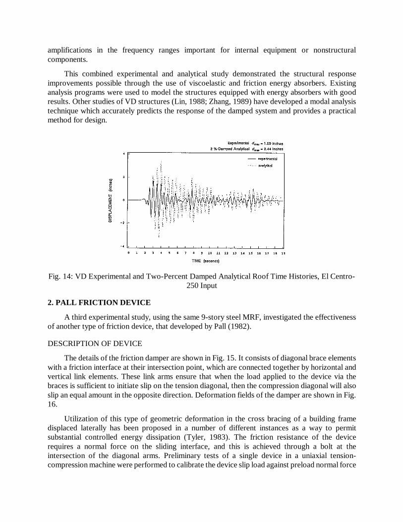
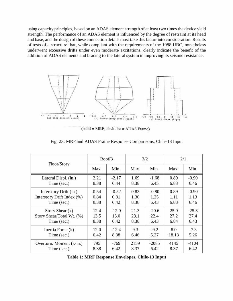
Although numerous earthquake tests of both structures were performed, only one test of eachstructure will be discussed in detail here. The ground motion used was the Llolleo N10E recordfrom the 1985 Chile earthquake, which was input to the MRF with a PGA of 0.13g and input to theADAS-frame with PGAs of 0.13g and 0.56g. These tests are referred to as Chile-13 and Chile-56,with effective peak accelerations (EPAs) of 0.10g and 0.46g, respectively. The response envelopesfor the structures subjected to these inputs are presented in Tables 1, 2, and 3. The peak interstorydrift index (ISI) for the MRF was 1.3 percent in the Chile-13 test; for the ADAS-frame it was 0.46percent in the Chile-13 test and 2.0 percent in the Chile-56 test. Responses to the Chile-13 test arecompared in Fig. 23. The response of the MRF to a ground motion with an EPA of only 0.10g wasclearly inadequate. The addition of the ADAS-bracing assemblage significantly improved theoverall performance of the structure and enabled it to withstand a much bigger EPA (0.46g) withacceptable drift responses.
SUMMARY
The research program demonstrated that ADAS elements possess characteristics that makethem suitable for use as energy dissipation devices in new and existing buildings. One practicalconfiguration for installing ADAS devices in a building is in conjunction with a chevron braceassemblage as was used in the test structure studied. The chevron assemblage must be designed
Fig. 22: MRF Retrofitted With ADAS Elements
using capacity principles, based on an ADAS element strength of at least two times the device yieldstrength. The performance of an ADAS element is influenced by the degree of restraint at its headand base, and the design of these connection details must take this factor into consideration. Resultsof tests of a structure that, while compliant with the requirements of the 1988 UBC, nonethelessunderwent excessive drifts under even moderate excitations, clearly indicate the benefit of theaddition of ADAS elements and bracing to the lateral system in improving its seismic resistance.
Fig. 23: MRF and ADAS Frame Response Comparisons, Chile-13 Input
Floor/StoryRoof/3 3/2 2/1
Max. Min. Max. Min. Max. Min.
Lateral Displ. (in.)Time (sec.)
2.218.38
-2.176.44
1.698.38
-1.686.45
0.896.83
-0.906.46
Interstory Drift (in.)Interstory Drift Index (%)
Time (sec.)
0.540.848.38
-0.520.816.42
0.831.308.38
-0.801.256.43
0.891.116.83
-0.901.136.46
Story Shear (k)Story Shear/Total Wt. (%)
Time (sec.)
12.413.58.38
-12.013.06.42
21.323.18.38
-20.622.46.43
25.027.26.84
-25.327.46.43
Inertia Force (k)Time (sec.)
12.06.42
-12.48.38
9.36.46
-9.25.27
8.018.13
-7.35.26
Overturn. Moment (k-in.)Time (sec.)
7958.38
-7696.42
21598.37
-20856.42
41458.37
-41046.42
Table 1: MRF Response Envelopes, Chile-13 Input

Floor/StoryRoof/3 3/2 2/1
Max. Min. Max. Min. Max. Min.
Lateral Displ. (in.)Time (sec.)
0.7112.43
-0.8114.92
0.5612.44
-0.6714.92
0.3212.45
-0.3714.92
Interstory Drift (in.)Interstory Drift Index (%)
Time (sec.)
0.170.2713.01
-0.200.3112.73
0.250.3913.00
-0.290.4514.92
0.320.4012.45
-0.370.4614.92
Story Shear (k)Story Shear/Total Wt. (%)
Time (sec.)
8.79.2
13.00
-9.510.012.72
14.014.712.43
-16.217.014.92
17.618.512.44
-20.521.514.92
Inertia Force (k)Time (sec.)
9.512.72
-8.713.00
7.914.92
-6.312.44
5.112.78
-4.714.65
Overturn. Moment (k-in.)Time (sec.)
55513.00
-60612.72
144613.00
-157014.92
279812.43
-321114.92
Table 2: ADAS-Frame Response Envelopes, Chile-13 Input
Floor/StoryRoof/3 3/2 2/1
Max. Min. Max. Min. Max. Min.
Lateral Displ. (in.)Time (sec.)
2.6312.54
-3.175.52
2.1612.54
-2.6512.86
1.3012.54
-1.6012.86
Interstory Drift (in.)Interstory Drift Index (%)
Time (sec.)
0.580.905.18
-0.661.035.50
0.901.405.17
-1.081.695.52
1.301.6212.54
-1.602.0012.86
Story Shear (k)Story Shear/Total Wt. (%)
Time (sec.)
21.622.75.17
-24.125.35.49
34.736.55.17
-41.243.45.51
46.849.312.53
-54.457.312.85
Inertia Force (k)Time (sec.)
24.15.49
-21.65.17
21.512.86
-17.012.54
15.412.84
-14.514.66
Overturn. Moment (k-in.)Time (sec.)
13835.16
-15415.49
35965.16
-41405.50
702012.53
-81065.50
Table 3: ADAS-Frame Response Envelopes, Chile-56 Input

4. STEEL MRF RETROFIT WITH FRICTION-SLIP DEVICES
Subsequent to shake table tests of the 9-story steel model with Pall friction dampers (Section2.), another type of friction device was developed for use in structures as part of a chevron bracingsystem (Giacchetti, 1989). This section describes the development and testing of this device, itsinclusion in a steel MRF, and shake table tests of the retrofitted structure.
DESCRIPTION AND TESTING OF DEVICES
Description
The friction-slip device (FSD) consists of two U-shaped steel casings and a sliding piecelocated between the casings (Fig. 24). The interface between the inner and outer pieces is facedwith a high-performance brake-pad material, and the normal force to the friction surface isdeveloped by prestressed bolts..
Component Tests
A single FSD was subjected to extensive dynamic tests in a uniaxial tension-compressionmachine to investigate its behavior characteristics. Possible factors affecting performance, such asvariation in bolt preload, temperature, rate of sliding, and misalignment were all quantified. For theinitial FSD design, misalignment of the inner and outer pieces was found to be a potential problem,so the design was modified. The design was improved to include oil-impregnated bearings actingas guide-plates between the inner and outer units. This refined design was subjected to dynamictests in a one-story, one-bay, chevron-braced subassemblage. These tests verified the refineddesign, and then the FSDs were installed in the test structure.
EARTHQUAKE SIMULATOR TESTS & RESULTS
Test Model
The test structure was originally designed in accordance with the 1979 UBC and the 1981Japanese Aseismic Code. The approximately 1/3-scale ductile steel MRF was two bays in plan, 6stories high, with a lightweight composite floor system (Fig. 25). Tests of the structure in moment-resisting, concentrically-braced, and eccentrically-braced configurations showed that the MRFsuffered excessive drifts under moderate and severe ground motions (Whittaker, 1990).
Fig. 24: Friction-Slip Device

The FSDs were included in the model as part of a chevron bracing system. They were locatedat the bottom end of each brace, adjacent to the beam-column-brace connection (Fig. 26). Byplacing the devices in this location, any deformations of the FSDs out-of-plane with thelongitudinal axis of the bracing would be negligible and not detrimental to their sliding behavior.
Free vibrations of the MRF and FSD-frame induced by pulse excitations were analyzed todetermine the dynamic characteristics of the structural systems. Natural frequencies were found tobe 1.45 Hz for the MRF, and 2.87 Hz for the FSD-frame. The addition of the chevron bracing andthe FSDs significantly stiffened the test structure.
Results
The MRF and FSD-frame were both subjected to the same set of earthquake inputs, and theFSD-frame was also subjected to more than 35 severe and very severe input motions. Only a fewtests of each structure are discussed here. Peak response quantities of the MRF subjected to fourdifferent inputs are listed in Table 4, and of the FSD-frame subjected to two different inputs inTable 5. Inelastic behavior of the MRF commenced for motions of about EPA = 0.20g, butexcessive interstory drifts (ISDs) occurred even for motions with EPAs less than 0.10g. An
Fig. 25: Plan and Elevation of 6-Story Ductile MRF

example of MRF inelastic behavior is the third-floor story shear-ISD relationship shown in Fig. 27for the Taft-34 (EPA = 0.27g) input. The maximum ISI for this test was 2.5 percent, whichoccurred at the third floor. For the SCT-43 test (EPA = 0.21g), the peak ISI was 4.5 percent.
After the inclusion of the FSD-chevron brace system, the poor performance of the MRF wasconsiderably improved. The Taft-86 (EPA = 0.72g) input caused a peak ISD of only 1.74 percent,while the Chile-100 (EPA = 0.65g) induced a maximum ISD of 1.51 percent. Third-floor storyshear vs. ISD, shear in the ductile MRF vs. ISD, and chevron brace shear (resolved FSD slip force)vs. ISD relationships for the Taft-86 input are all shown in Fig. 28. It is clear that there is noinelastic action in the primary MRF, and that the energy dissipation represented in the story shear-ISD plot is due to the FSDs alone.
SIGNAL
Max. Interstory
Drift(inches)
Max. Interstory Drift Index PGA
(g)EPA(g)
(%) story
Taft-09 0.18 0.41 4 0.11 0.09 0.07
Taft-10 0.48 1.14 4 0.30 0.10 0.09
Taft-34 1.00 2.45 3 0.41 0.34 0.27
SCT-43 1.85 4.53 3 0.47 0.43 0.21
Table 4: MRF Interstory Drift and Shear Maxima
SIGNAL
Max. Interstory
Drift(inches)
Max. Interstory Drift Index PGA
(g)EPA(g)
(%) story
Taft-86 0.72 1.74 4 0.44 0.86 0.72
Chile-100 0.61 1.51 5 0.48 1.00 0.65
Table 5: FSD-Frame Interstory Drift and Shear Maxima
Fig. 26: MRF 3rd Floor Story Shear vs. ISD, Taft-34 Input
MaxBaseShearW-------------------------------------
MaxBaseShearW-------------------------------------

SUMMARY
A friction energy dissipator was developed and used to successfully retrofit a ductile steelMRF, providing the structure with a substantially greater energy dissipation capability and greaterstiffness to control drifts during severe loadings. Inelastic action in primary structural members ofthe MRF was avoided and energy dissipated instead in the friction devices within a chevronbracing system. The inherent lack of ductility in a chevron system is overcome by including FSDsin the bracing and using capacity design methods. The FSD-chevron system represents asignificant improvement over conventional concentrically-braced, or even eccentrically-bracedstructural systems by concentrating energy dissipation in elements best suited to this task and notby demanding inelastic action in primary gravity load-resisting structural members.
II. SMALL-SCALE EARTHQUAKE SIMULATOR STUDIES
1. FLUOR-DANIEL ENERGY-DISSIPATING RESTRAINT
This section presents a summary of the test results of the Fluor Daniel, Inc. EnergyDissipating Restraint (EDR) and tests studying the use of Nickel Titanium shape memory alloy(NiTi or Nitinol) as an energy dissipating element. Both series of tests were performed on the samesmall-scale 3-story steel frame. More details of the results of these tests are provided by Richter(1990) and Aiken (1992).
DESCRIPTION OF TEST FACILITY AND MODEL STRUCTURE
A small shake table at the EERC was used for these tests. The table is 1.42 m by 1.22 m (4 ft.8 in x 4 ft.) in plan, with one horizontal degree of freedom and a payload capacity of 45 kN (10kips). The model was a three-story steel moment-resisting frame of all-welded construction. Themodel was 0.91 m x 1.22 m (3 ft x 4 ft.) in plan and the total weight was 18.9 kN (4.02 kips) equallydistributed between the floors. The damping of the bare model was 0.5 percent, and the threetranslational frequencies in the direction of testing were 2.6 Hz, 10.9 Hz, and 24.5 Hz.
Fig. 27: FSD-Frame 3rd Floor Story Shear vs. ISD Relationships, Taft-86 Input

ENERGY DISSIPATING RESTRAINT
The Energy Dissipating Restraint (EDR) was originally developed as a seismic restraintdevice for the support of piping systems in nuclear power plants. The mechanism of the EDR issliding friction through a range of motion with a stop at the end of that range of motion. A fulldescription of the EDR mechanical behavior and detailed diagrams of the device are given by Nims(1993) elsewhere in this issue. The features of the device are its self-centering capability and thatthe frictional force is proportional to the displacement. Depending on the spring constant of thecore, the initial slip load, the configuration of the core, and the gap size, several different types ofhysteretic behavior are possible. Two typical test hysteresis loops for different adjustments of thedevice are shown in Fig. 29.
EDR Test Program
The EDR frame tests used two earthquake ground motions: El Centro (1940, S00Wcomponent, 1/2-time scale) and Zacatula (1985 Michoacan). The El Centro signal has a stronginitial pulse while the Zacatula signal is more regular.
Two EDRs were mounted in each of the three stories of the model. Sketches of the modelwithout and with the EDRs installed are shown in Figs. 30 and 31. A view of the EDRs installedin the second level of the model is shown in Fig. 32.
The principal variable changed during the testing was the initial slip load, and, for themajority of the tests performed, the slip load distribution was uniform throughout the model. Inaddition to the tests with the device in the self-centering configuration, a series of tests with theEDR configured to act as a simple Coulomb device were also performed.
Fig. 28: Hysteresis Loop Shapes for Different EDS Adjustments

Summary of Test Results
Figs. 33a and b show profiles of the peak accelerations, interstory drifts and displacementsrelative to the ground for the El Centro (PGA = 0.33g) and the Zacatula (PGA = 0.36g) inputs. Oneach figure, the response of the bare frame and the EDR with slip loads of 335, 555, 890, and 1335N (75, 125, 200, and 300 lbs) are compared.
The overall effect of the EDR was to substantially reduce the model deformations andinterstory drifts. Interstory drifts and displacements consistently decreased with increasing slipload. Acceleration trends were not as well defined.
Part of the change in structural response was due to the change in the stiffness of the structurewith the EDRs in place and part was due to the additional damping the EDRs added to the structure.The change in stiffness was substantial, with the fundamental frequency being 3.9 Hz for the EDRframe (2.6 Hz for the bare frame). The shift in frequency depended on the slip load, the slip loadconfiguration, and the frequency content of the input.
A series of linear-elastic response spectrum analyses were used to approximately segregatethe effects of damping and stiffness. The response spectrum analysis was performed using themeasured predominant frequency and mode shape for the EDR frame, but the damping was takenas that of the bare frame. The response spectrum results show the relative displacement of theframe with the shifted frequency and changed mode shape, but with the 0.5 percent damping of thebare frame. This approach identifies the relative effects of added damping and added stiffness tothe response of the model. Because the mode shape does not change a great deal as the slip loadvaries, all the results can be normalized to one spectrum analysis curve. The reduction in responsebelow this level is due to the added hysteretic damping of the EDRs. Fig. 34 shows the results ofa series of response spectrum analyses for the Zacatula signal. These figures indicate the seminalresult of the EDR testing: the additional damping provided by the EDR significantly reduces thestructural response. It can be seen from these figures that the damping contributes substantially tothe reduction in relative displacement and that the higher the slip load the greater the displacementresponse reduction.

Fig. 29: Bare Frame
Fig. 30: Frame with Energy Dissipating Restraints
Fig. 31: View of EDRs Installed at Second Level of Frame

Fig. 32: EDR Frame Response Profiles

One advantage of the EDR is that it can be effective at low levels of seismic input or for windloading, while also being effective at high seismic inputs. This is because the slip force and thusthe energy dissipated is proportional to the displacement of the EDR. Another advantage is that theself-centering behavior would tend to reduce permanent offsets if the structure were deformedinelastically.
2. NiTi SHAPE-MEMORY ALLOY DAMPERS
The shape memory effect in metals was first observed in the 1930s. In 1962, researchers atthe Naval Ordinance Laboratory observed the phenomenon in Nickel-Titanium (NiTi, or Nitinol).Shape-memory alloys (SMAs) have the capacity to undergo large strains and subsequently recovertheir initial configurations. The basis for this behavior is that, rather than deforming in the usualmanner of metals, shape-memory alloys undergo transformations from the austenitic to themartensitic crystal phase (Hodgson, 1988).
Among the growing number of applications of SMAs, the largest single use to date has beenin hydraulic pipe couplings. The coupling is cooled to expand its diameter and assembled. Then asit warms to room temperature it recovers its smaller diameter and locks. Other SMA applicationsare circuit-board connectors, eyeglass frames (with shape memory or superelastic properties),blood clot filters that are inserted into veins and expand due to body temperature, and a number ofother medical and dental applications. Sasaki (1989) studied the suitability of Nitinol for energydissipation under seismic-type loading, and investigated flexural, torsional, shear, and axial modesof deformation. Graesser (1991) and Witting (1992) have continued the studies of shape memoryalloys for energy dissipation applications in structures.
In most current commercial applications, the phase change is temperature induced, however,it can be stress induced at room temperature if the Nitinol has the appropriate formulation andtreatment. This stress-induced phase change phenomenon is referred to as superelasticity. Fig. 35illustrates the theoretical behavior of Nitinol as it is loaded in tension.
Fig. 33: Effect of Damping on Response - Experimental and Analytical Response Profiles

The key characteristic is that if the strain is less than there is no permanent deformation.In this testing, Nitinol wire was incorporated in series as part of a cross-bracing system in themodel. In this configuration, the Nitinol was loaded only in tension, which allowed the full volumeof the Nitinol to effectively dissipate energy. A view of the Nitinol cross bracing in the top floorof the model is shown in Fig. 36a, and a close-up view of the Nitinol wire is shown in Fig. 36b.
Summary of Test Results
The force-deformation behavior of the Nitinol cross bracing that was achieved with nopreload in the wire is shown in Fig. 37. Because there was no preload, the wire was able to go slackduring compressive portions of the dynamic loading, and as expected, the hysteresis loop showsthis behavior for strains up to about 4 percent. One desirable feature of the Nitinol is that itsstrength increases when is exceeded. This means that if the predicted earthquake excitationwere to be exceeded, the structure would stiffen rather than soften. When the strain in the materialwas increased to 8 percent, the hysteretic behavior shown in Fig. 38 was obtained. This loop showsall of the characteristics which are theoretically predicted and were exhibited in the static tests. Inthese loops there was no preload, and because permanent deformation of the wire occurred duringthe larger strain cycles the wire was loose at the end of the test.
Fig. 34: Superelasticity
εel
εel

Fig. 35: Installation of Nitinol Wire Device in Model Bracing
Fig. 36: Nitinol Moderate-Strain Hysteresis Behavior

Fig. 37: Nitinol High-Strain Hysteresis Behavior
Fig. 38: Nitinol Hysteresis Behavior With Pre-Strain Applied

Fig. 39: Hysteresis Loops for All Nitinol Braces From a Typical Test
Fig. 40: Effect of Nitinol Braces on Response - Zacatula (span = 100)

With a small preload, it was difficult to achieve uniform behavior in all six braces. To resolvethis problem a large preload was applied to the Nitinol (Fig. 39). With the preload applied, thestrain in the Nitinol was between 2.5 and 6 percent throughout the testing. Thus, the Nitinol wascontinuously cycled in the region of hysteresis behavior where the most energy is dissipated. Withthis loading the Nitinol behaved smoothly in every brace and the behavior was uniform in all of thebraces. This is illustrated in Fig. 40, which shows hysteresis loops for both braces in each of thethree floors. The loops for all of the floors are similar, and all loops exhibit significant dissipatedenergy.
The effect of the Nitinol braces on the seismic response of the model under the Zacatulamotion is shown in Fig. 41. Results are shown for the bare frame, the frame with the Nitinolallowed to go slack (20 strnds slk), and the Nitinol with preload (20 strnds prld). The addition ofthe Nitinol braces significantly reduced the response in both cases. However, the preloaded Nitinolbraces caused a greater reduction in all three response parameters. As was found for the EDR, theNitinol energy dissipator was more effective for the regular Zacatula motion than for the impulsiveEl Centro motion.
SUMMARY
The EDR is a friction-based mechanical energy dissipator which has a wide range of possiblehysteretic behaviors. The most interesting behavior possesses fat “S-shaped” loops and is self-centering. In this configuration, the friction force dissipating the energy is proportional to thedisplacement and the internal preload of the EDR. By its design, the EDR increased both thestiffness and damping of the model. The influence of the added damping was shown to contributesignificantly to the reduction in response. One advantage of the EDR is that it can be effective atlow levels of seismic excitation or for wind loads while also being effective at high seismic levels.This is because the energy dissipated is proportional to the displacement of the EDR. The testinghas established the potential of the EDR as an energy dissipator for building applications.
Nitinol demonstrated the special ability to “yield” repeatedly and not lose its preload. Thedamping in the structure increased from 0.5 to 3.0 percent, and all of the structural responses werereduced. A Nitinol energy dissipator has the particular advantages of being mechanically verysimple and reliable.
III. CONCLUSIONS
In a number of different research programs at EERC, at total of seven types of passive energydissipators have been tested under earthquake shaking conditions in four different modelstructures.
Large-scale tests of a 9-story steel MRF incorporating two types of friction dampers and onetype of viscoelastic damper; tests of a 3-story steel MRF incorporating ADAS elements; tests of a6-story steel MRF incorporating friction dampers in chevron bracing; and small-scale tests of a 3-story steel model incorporating friction dampers and shape-memory alloy dampers, have beenperformed. The effectiveness of the various types of dampers was evaluated by comparing theresponse of the structures containing the dampers with the response of the same structures with nodampers or with conventional types of bracing. The benefits of the energy dissipators have beenclearly demonstrated by these comparisons, and also by associated analytical studies. The

improvements in performance have been shown to stem primarily from the increase in energydissipation available within the structure.
ACKNOWLEDGEMENTS
Many organizations and individuals contributed to these research studies. Grants from theNational Science Foundation and NCEER supported several of the programs. The followingcompanies are recognized for their financial and/or materials support: Bechtel, CounterQuakeCorp., Fluor Daniel, Inc., Sumitomo Metal Industries, Ltd. of Tokyo, Japan, and 3M Co. Thefollowing individuals are also acknowledged: Darel Hodgson of Shape Memory Applications, Inc.,Robert Krumme of E*Sorb Systems, and Dr. A. S. Pall of Pall Dynamics, Ltd., of Montreal,Canada. The opinions expressed in this paper are those of the authors only and do not necessarilyreflect the opinions of the sponsors.
REFERENCES
Aiken, I.D., Kelly., J.M., and Pall, A.S., 1988. “Seismic Response of a Nine-Story Steel Frame with Friction Damped Cross-Bracing,” Proc., 9WCEE, Tokyo/Kyoto, Japan.
Aiken, I.D., Kelly., J.M., and Mahmoodi, P., 1990a. “The Application of Viscoelastic Dampers to Seismically Resistant Structures,” Proc., 4USNCEE, Palm Springs, Calif.
Aiken, I.D., and Kelly, J.M., 1990b. “Earthquake Simulator Testing and Analytical Studies of Two Energy-Absorbing Systems for Multistory Structures,” Report UCB/EERC-90/03, Earthquake Eng. Res. Ctr, Univ. of California, Berkeley.
Aiken, I.D., Nims, D.K., and Kelly, J.M., 1992. “Comparative Study of Four Passive Energy Dissipation Systems,” Bull. N.Z. Nat. Soc. for Earthquake Eng., Vol. 25, No. 3.
Bergman, D.M., and Goel, S.C., 1987. “Evaluation of Cyclic Testing of Steel-Plate Devices for Added Damping and Stiffness,” Report UMCE 87-10, Dept. of Civil Eng., Univ. of Michigan, Ann Arbor.
Boardman, P.R., Wood. B.J., and Carr, A.J., 1983. “Union House — A Cross Braced Structure With Energy Dissipators,” Bull. N.Z. Nat. Soc. for Earthquake Eng., Vol. 16, No. 2.
Fiero, E., Perry, C., Sedarat, H., and Scholl, R., 1993. “Seismic Retrofit in San Francisco Using Energy Dissipation Devices,” submitted to Earthquake Spectra, Special Issue, Vol. 9, No. 3, EERI.
Filiatrault, A., and Cherry, S., 1990a. “Seismic Design Spectra for Friction Damped Structures,” Jnl of the Str. Div., Vol. 116, No. ST5, ASCE, New York.
Filiatrault, A., and Cherry, S., 1990b. “A Simplified Seismic Design Procedure for Friction Damped Structures,” Proc., 4USNCEE, Palm Springs, Calif.
Giacchetti, R., Whittaker, A.S., Bertero, V.V., and Aktan, H.M., 1989. “Seismic Response of A DMRSF Retrofitted With Friction Slip Devices,” Proc., First Int. Meeting on Base Isolation and Passive Energy Dissipation, Assisi, Italy.

Graesser, E.J., and Cozzarelli, F.A., 1991. “Shape Memory Alloys as New Materials for Aseismic Isolation,” Jnl of Eng. Mechs., Vol. 117, No. 11, ASCE, New York.
Hodgson, D.E., 1988. “Using Shape Memory Alloys,” Shape Memory Applications, Inc., Sunnyvale, Calif.
Keel, C.J., and Mahmoodi, P., 1986. “Design of Viscoelastic Dampers for the Columbia Center Building,” Building Motion in Wind, ASCE, New York.
Kelly, J.M., Skinner, R.I., and Heine, A.J., 1972. “Mechanisms of Energy Absorption in Special Devices for Use in Earthquake-Resistant Structures,” Bull. N.Z. Nat. Soc. for Earthquake Eng., Vol. 5, No. 3.
Kelly, J.M., and Skinner, M.S., 1980. “Development and Testing of Restraints for Nuclear Piping Systems,” Report UCB/EERC-80/21, Earthquake Eng. Res. Ctr, Univ. of California, Berkeley.
Lin, R.C., Liang, Z., Soong, T.T., and Zhang, R.H., 1988. “An Experimental Study of Seismic Structural Response With Added Viscoelastic Dampers,” Report NCEER-88-0018, NCEER, State Univ. of New York at Buffalo.
Mahmoodi, P., 1969. “Structural Dampers,” Jnl of the Str. Div., Vol. 95, No. ST8, ASCE, New York.
Mahmoodi, P., Robertson, L.E., Yontar, M., Moy, C., and Feld, L., 1987. “Performance of Viscoelastic Dampers in World Trade Center Towers,” Proc., 5th ASCE Strs. Cong., Orlando, Florida.
Mahmoodi, P., and Keel, C.J., 1989. “Analysis and Design of Multi-Layer Viscoelastic Dampers for Tall Structures,” Proc., 7th ASCE Strs. Cong., San Francisco, Calif.
Nims, D.K., Richter, P.J., and Bachman, R.E., 1993. “The Use of the Energy Dissipating Restraint for Seismic Hazard Mitigation,” submitted to Earthquake Spectra, Special Issue, Vol. 9, No. 3, EERI.
Pall,A.S., and Marsh, C., 1982. “Seismic Response of Friction Damped Braced Frames,” Jnl of the Str. Div., Vol. 108, No. ST6, ASCE, New York.
Pall,A.S., Verganelakis, V., and Marsh, C., 1987. “Friction Dampers for Seismic Control of Concordia Library Building,” Proc., 5th Canadian Conf. on Earthquake Eng., Ottawa, Canada.
Pall,A.S., Ghorayeb, F., and Pall, R., 1991. “Friction-Dampers for Rehabilitation of Ecole Polyvalente at Sorel, Quebec,” Proc., 6th Canadian Conf. on Earthquake Eng., Toronto, Canada.
Richter, P.J., Nims, D.K., Kelly, J.M., and Kallenback, R.M., 1990. “The EDR-Energy Dissipating Restraint, A New Device for Mitigating Seismic Effects,” Proc., SEAOC Ann. Conv., SEAOC, Lake Tahoe.
Sasaki, K., 1989. “Experimental Evaluation of Nitinol for Energy Dissipating Devices,” Report UCB/SEMM-89/20, Dept. of Civil Eng., Univ. of California, Berkeley.

Steimer, S.F., and Godden, W.G., 1980. “Shaking Table Tests of Piping Systems With Energy-Absorbing Restrainers,” Report UCB/EERC-80/33, Earthquake Eng. Res. Ctr, Univ. of California, Berkeley.
Steimer, S.F., Godden, W.G., and Kelly, J.M., 1981. “Experimental Behavior of a Spatial Piping System With Steel Energy Absorbers Subjected to a Simulated Differential Seismic Input,” Report UCB/EERC-81/09, Earthquake Eng. Res. Ctr, Univ. of California, Berkeley.
Steimer, S.F., and Chow, F.L., 1984. “Curved Plate Energy Absorbers for Earthquake Resistant Structures,” Proc., 8WCEE, San Francisco, Calif.
Tyler, R.G., 1978. “Tapered Steel Cantilever Energy Absorbers,” Bull. N.Z. Nat. Soc. for Earthquake Eng., Vol. 11, No. 4.
Tyler, R.G., 1983. “Preliminary Tests on an Energy Absorbing Element for Braced Structures Under Earthquake Loading,” Bull. N.Z. Nat. Soc. for Earthquake Eng., Vol. 16, No. 3.
Uang, C.-M. and Bertero, V.V., 1988. “Use of Energy as a Design Criterion in Earthquake Resistant Design,” Report UCB/EERC-88/18, Earthquake Eng. Res. Ctr, Univ. of California, Berkeley.
Vezina, S., Proulx, P., Pall, R., and Pall, A.S., 1992. “Friction-Dampers for Aseismic Design of Canadian Space Agency,” Proc., 10WCEE, Madrid, Spain.
Whittaker, A.S., Uang, C.-M., and Bertero, V.V., 1990. “An Experimental Study of the Behavior of Dual Steel Systems,” Report UCB/EERC-88/14, Earthquake Eng. Res. Ctr, Univ. of California, Berkeley.
Whittaker, A.S., Bertero, V.V., Thompson, C.L., and Alonso, L.J., 1991. “Seismic Testing of Steel Plate Energy Dissipation Devices,” Earthquake Spectra, Vol. 7, No. 4, EERI.
Witting, P.R., and Cozzarelli, F.A, 1992. “Shape Memory Structural Dampers: Material Properties, Design and Seismic Testing,” Report NCEER-92-0013, NCEER, State Univ. of New York at Buffalo.
Yokota, H., Saruta, M., Nakamura., Y., Satake, N., and Okada, K., 1992. “Structural Control for Seismic Load Using Viscoelastic Dampers,” Proc., 10WCEE, Madrid, Spain.
Zhang, R.H., Soong, T.T., and Mahmoodi, P., 1989. “Seismic Response of Steel Frame Structures With Added Viscoelastic Dampers, Earthquake Eng. & Str. Dyn., Vol. 18, No. 3.