Embed Size (px)
DESCRIPTION
Testing of Test Structures in Vienna. CMS Sensor-TUPO. CMS Process Qualification Center 2001-2007. History. TS-CAP. baby. diode. MOS 2. GCD. sheet. CAP-TS-AC. CAP-TS-AC. MOS 1. Process Monitoring on Test Structures. What is Process monitoring? - PowerPoint PPT Presentation
Citation preview
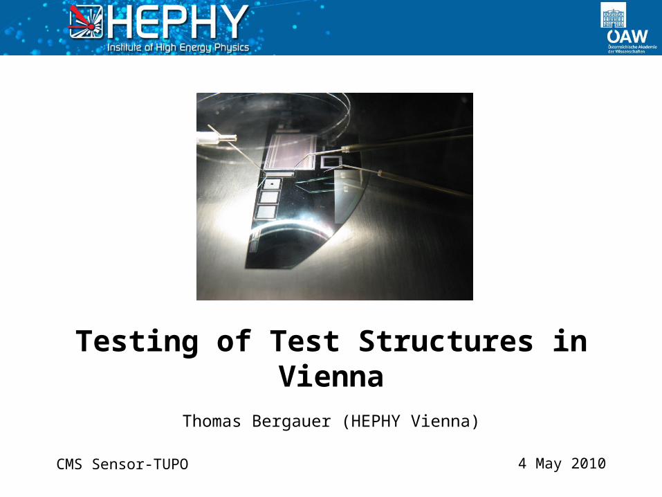
4 May 2010
Thomas Bergauer (HEPHY Vienna)
Testing of Test Structures in Vienna
CMS Sensor-TUPO
CMS Sensor-TUPO
HISTORY
CMS Process Qualification Center 2001-2007
2Thomas Bergauer (HEPHY Vienna)4 May 2010
CMS Sensor-TUPO
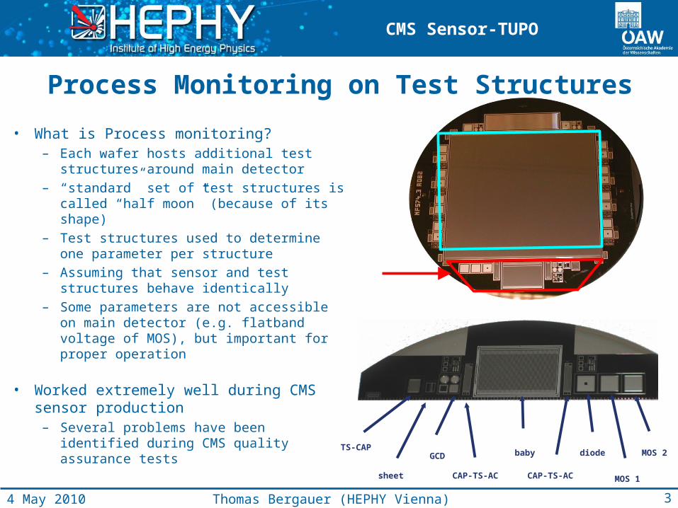
Process Monitoring on Test Structures
• What is Process monitoring?– Each wafer hosts additional test
structures around main detector– “standard” set of test structures is called
“half moon” (because of its shape)– Test structures used to determine one
parameter per structure– Assuming that sensor and test structures
behave identically– Some parameters are not accessible on
main detector (e.g. flatband voltage of MOS), but important for proper operation
• Worked extremely well during CMS sensor production
– Several problems have been identified during CMS quality assurance tests
TS-CAP
sheet
GCD
CAP-TS-AC CAP-TS-AC
baby diode
MOS 1
MOS 2
3Thomas Bergauer (HEPHY Vienna)4 May 2010
CMS Sensor-TUPO
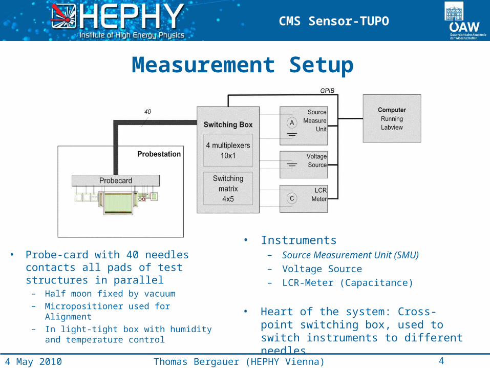
Measurement Setup
• Probe-card with 40 needles contacts all pads of test structures in parallel
– Half moon fixed by vacuum
– Micropositioner used for Alignment
– In light-tight box with humidity and temperature control
• Instruments– Source Measurement Unit (SMU)– Voltage Source– LCR-Meter (Capacitance)
• Heart of the system: Cross-point switching box, used to switch instruments to different needles
4Thomas Bergauer (HEPHY Vienna)4 May 2010
CMS Sensor-TUPO
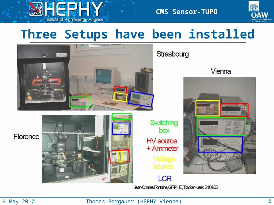
Three Setups have been installed
5Thomas Bergauer (HEPHY Vienna)4 May 2010
CMS Sensor-TUPO
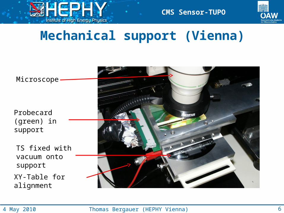
Mechanical support (Vienna)
Microscope
Probecard (green) in support
TS fixed with vacuum onto support
XY-Table for alignment
6Thomas Bergauer (HEPHY Vienna)4 May 2010
CMS Sensor-TUPO
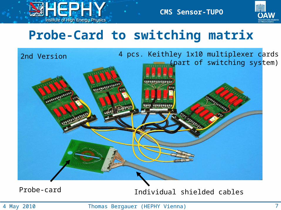
Probe-Card to switching matrix
2nd Version
Individual shielded cables
7Thomas Bergauer (HEPHY Vienna)4 May 2010
Probe-card
4 pcs. Keithley 1x10 multiplexer cards(part of switching system)
CMS Sensor-TUPO
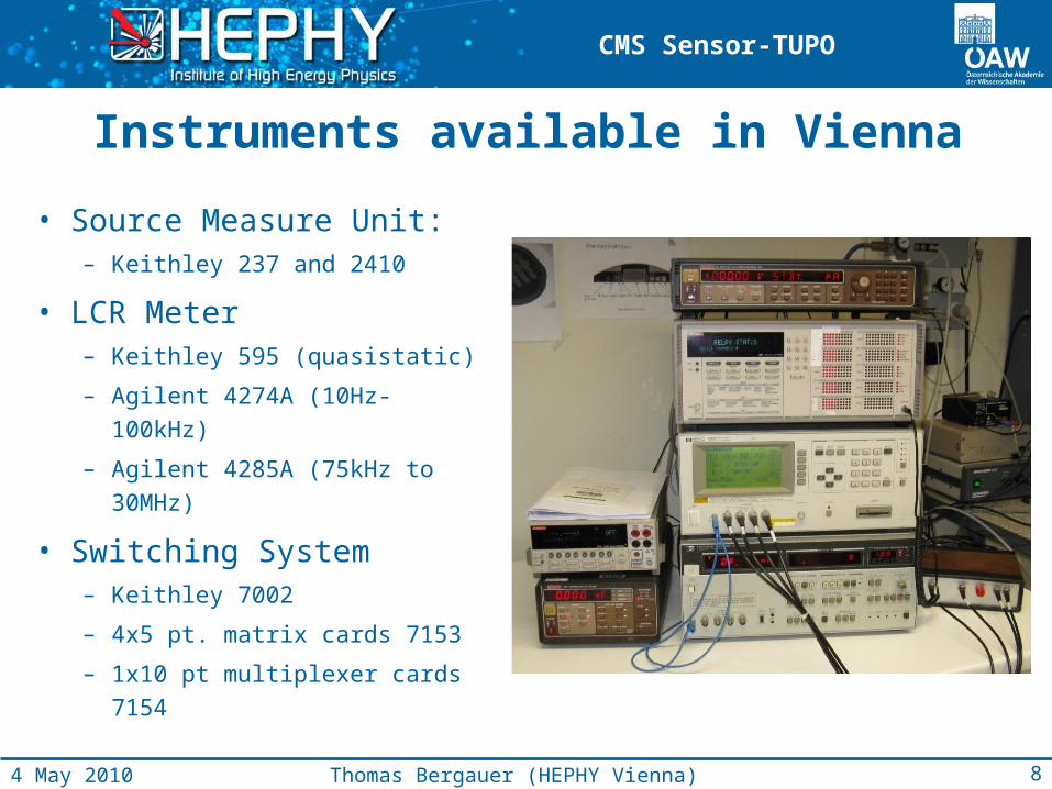
Instruments available in Vienna
• Source Measure Unit:– Keithley 237 and 2410
• LCR Meter– Keithley 595 (quasistatic)
– Agilent 4274A (10Hz-100kHz)
– Agilent 4285A (75kHz to
30MHz)
• Switching System– Keithley 7002
– 4x5 pt. matrix cards 7153
– 1x10 pt multiplexer cards 7154
8Thomas Bergauer (HEPHY Vienna)4 May 2010
CMS Sensor-TUPO
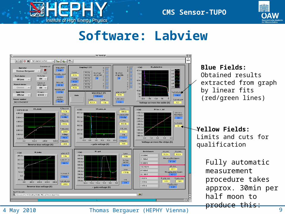
Yellow Fields: Limits and cuts for qualification
Blue Fields: Obtained resultsextracted from graphby linear fits (red/green lines)
Software: Labview
Fully automatic measurement procedure takes approx. 30min per half moon to produce this:
9Thomas Bergauer (HEPHY Vienna)4 May 2010
CMS Sensor-TUPO
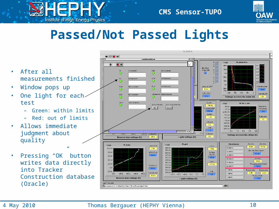
Passed/Not Passed Lights
• After all measurements finished
• Window pops up• One light for each test
– Green: within limits
– Red: out of limits
• Allows immediate judgment about quality
• Pressing “OK” button writes data directly into Tracker Construction database (Oracle)
10Thomas Bergauer (HEPHY Vienna)4 May 2010
CMS Sensor-TUPO
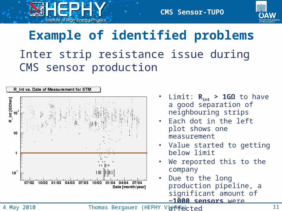
Example of identified problems
• Limit: Rint > 1GΩ to have a good separation of neighbouring strips
• Each dot in the left plot shows one measurement
• Value started to getting below limit
• We reported this to the company• Due to the long production
pipeline, a significant amount of ~1000 sensors were affected
Inter strip resistance issue during CMS sensor production
11Thomas Bergauer (HEPHY Vienna)4 May 2010
CMS Sensor-TUPO
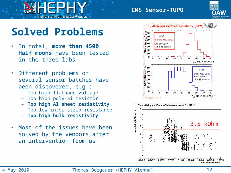
• In total, more than 4500 Half moons have been tested in the three labs
• Different problems of several sensor batches have been discovered, e.g.:
– Too high flatband voltage– Too high poly-Si resistor– Too high Al sheet resistivity– Too low inter-strip resistance– Too high bulk resistivity
• Most of the issues have been solved by the vendors after an intervention from us
3.5 kOhm
12Thomas Bergauer (HEPHY Vienna)4 May 2010
Solved Problems
CMS Sensor-TUPO
ACTUAL SETUP FOR SLHC UPGRADE
Instruments and Cold Chuck
14Thomas Bergauer (HEPHY Vienna)4 May 2010
CMS Sensor-TUPO
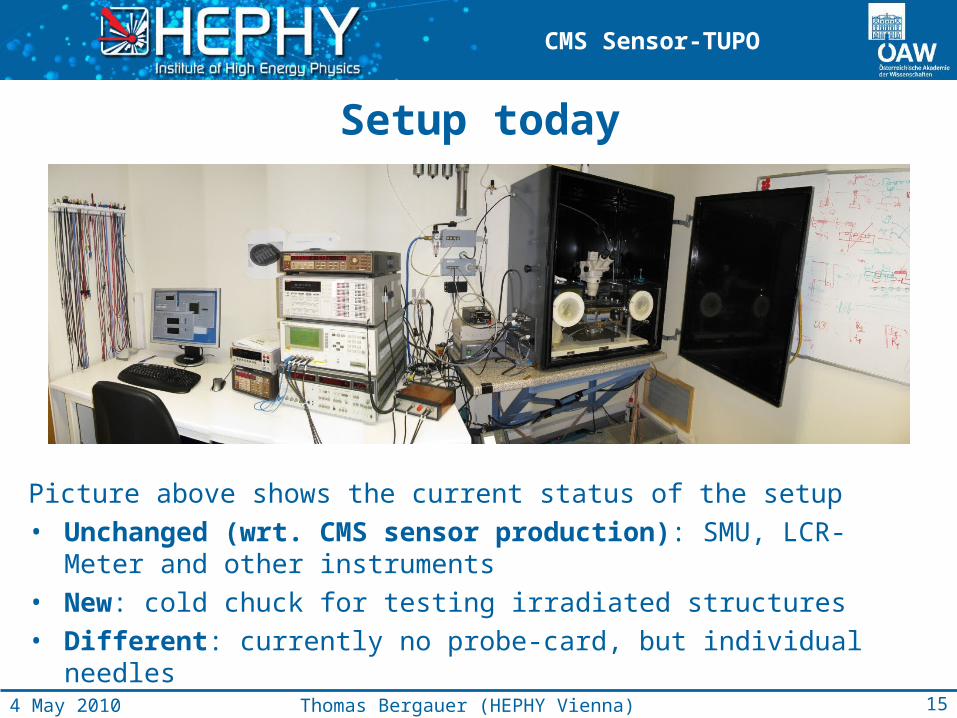
Setup today
Picture above shows the current status of the setup• Unchanged (wrt. CMS sensor production): SMU, LCR-Meter and
other instruments• New: cold chuck for testing irradiated structures• Different: currently no probe-card, but individual needles
15Thomas Bergauer (HEPHY Vienna)4 May 2010
CMS Sensor-TUPO
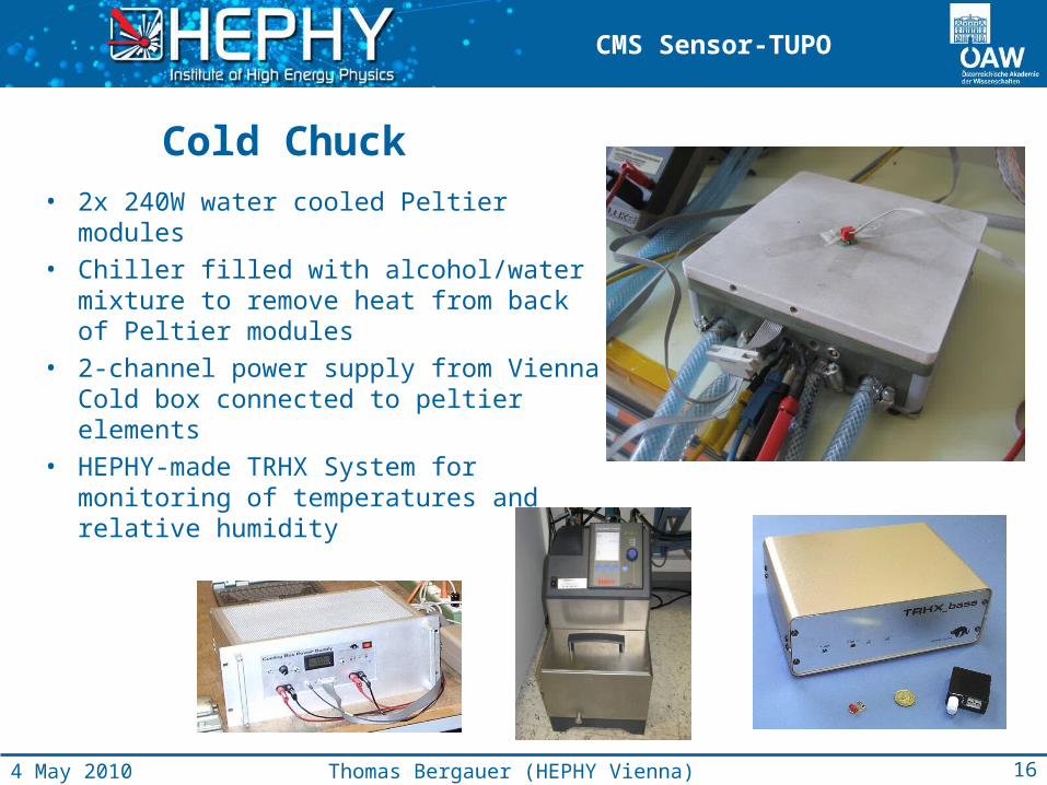
Cold Chuck
• 2x 240W water cooled Peltier modules• Chiller filled with alcohol/water mixture
to remove heat from back of Peltier modules
• 2-channel power supply from Vienna Cold box connected to peltier elements
• HEPHY-made TRHX System for monitoring of temperatures and relative humidity
16Thomas Bergauer (HEPHY Vienna)4 May 2010
CMS Sensor-TUPO
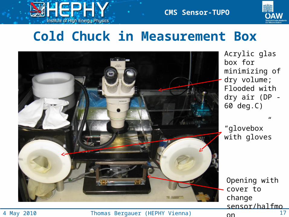
Cold Chuck in Measurement Box
17Thomas Bergauer (HEPHY Vienna)4 May 2010
Acrylic glas box for minimizing of dry volume;Flooded with dry air (DP -60 deg.C)
“glovebox” with gloves
Opening with cover to change sensor/halfmoon
CMS Sensor-TUPO
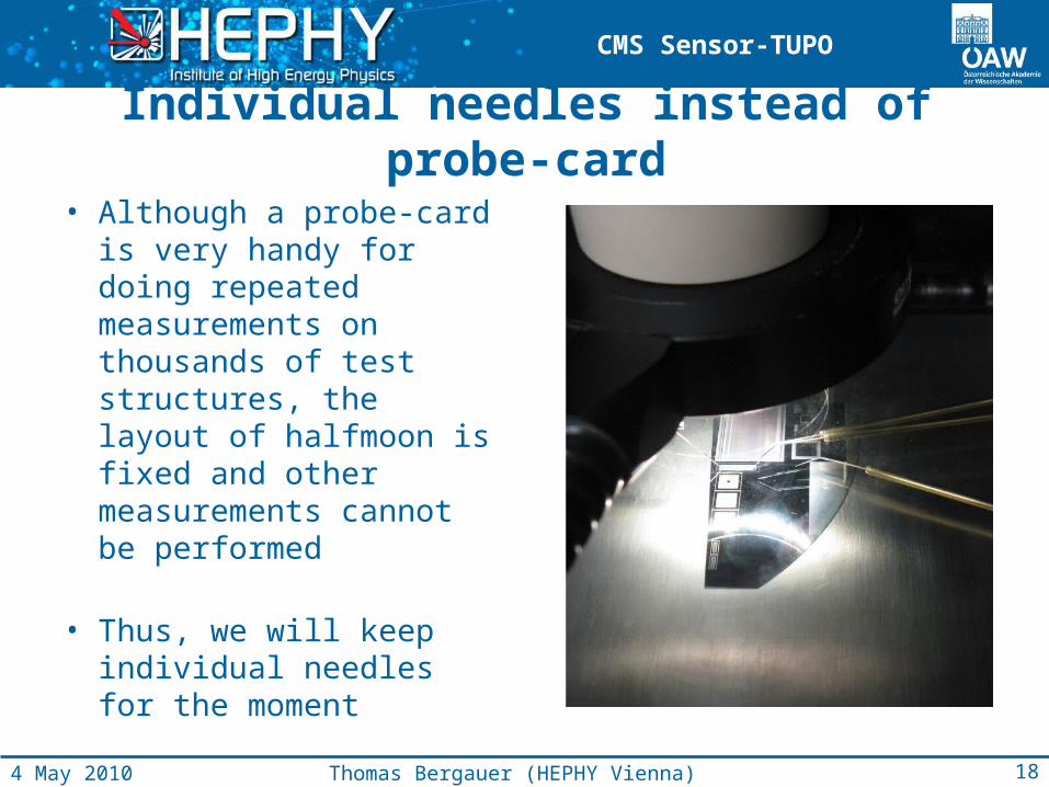
Individual needles instead of probe-card
• Although a probe-card is very handy for doing repeated measurements on thousands of test structures, the layout of halfmoon is fixed and other measurements cannot be performed
• Thus, we will keep individual needles for the moment
18Thomas Bergauer (HEPHY Vienna)4 May 2010
CMS Sensor-TUPO
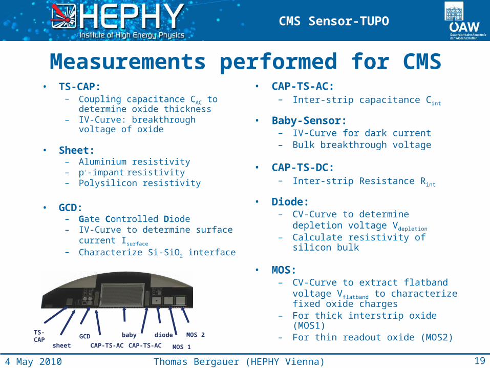
Measurements performed for CMS• TS-CAP:
– Coupling capacitance CAC to determine oxide thickness
– IV-Curve: breakthrough voltage of oxide
• Sheet:– Aluminium resistivity– p+-impant resistivity– Polysilicon resistivity
• GCD: – Gate Controlled Diode– IV-Curve to determine surface
current Isurface
– Characterize Si-SiO2 interface
• CAP-TS-AC: – Inter-strip capacitance Cint
• Baby-Sensor: – IV-Curve for dark current– Bulk breakthrough voltage
• CAP-TS-DC: – Inter-strip Resistance Rint
• Diode:– CV-Curve to determine depletion
voltage Vdepletion – Calculate resistivity of silicon bulk
• MOS: – CV-Curve to extract flatband voltage
Vflatband to characterize fixed oxide charges
– For thick interstrip oxide (MOS1)– For thin readout oxide (MOS2)
TS-CAP
sheet
GCD
CAP-TS-AC CAP-TS-AC
baby diode
MOS 1
MOS 2
19Thomas Bergauer (HEPHY Vienna)4 May 2010
CMS Sensor-TUPO
Measurements performed so far
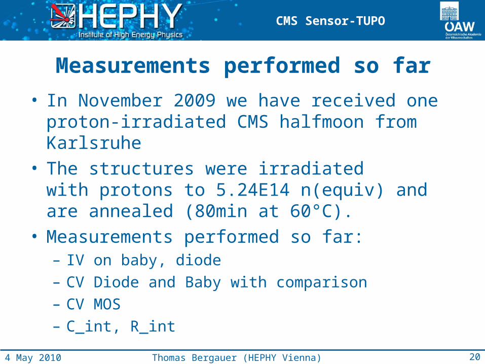
• In November 2009 we have received one proton-irradiated CMS halfmoon from Karlsruhe
• The structures were irradiated with protons to 5.24E14 n(equiv) and are annealed (80min at 60°C).
• Measurements performed so far:– IV on baby, diode– CV Diode and Baby with comparison– CV MOS– C_int, R_int
20Thomas Bergauer (HEPHY Vienna)4 May 2010
CMS Sensor-TUPO
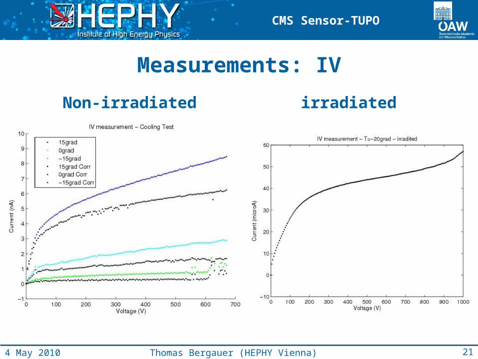
Measurements: IV
Non-irradiated irradiated
21Thomas Bergauer (HEPHY Vienna)4 May 2010
CMS Sensor-TUPO
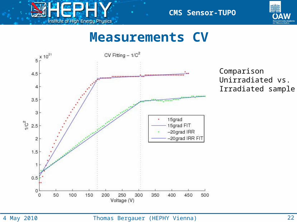
Measurements CV
Comparison Unirradiated vs.Irradiated sample
22Thomas Bergauer (HEPHY Vienna)4 May 2010
CMS Sensor-TUPO
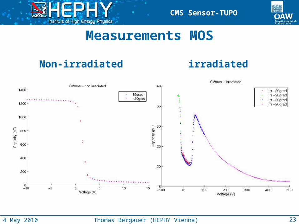
Measurements MOS
Non-irradiated irradiated
23Thomas Bergauer (HEPHY Vienna)4 May 2010
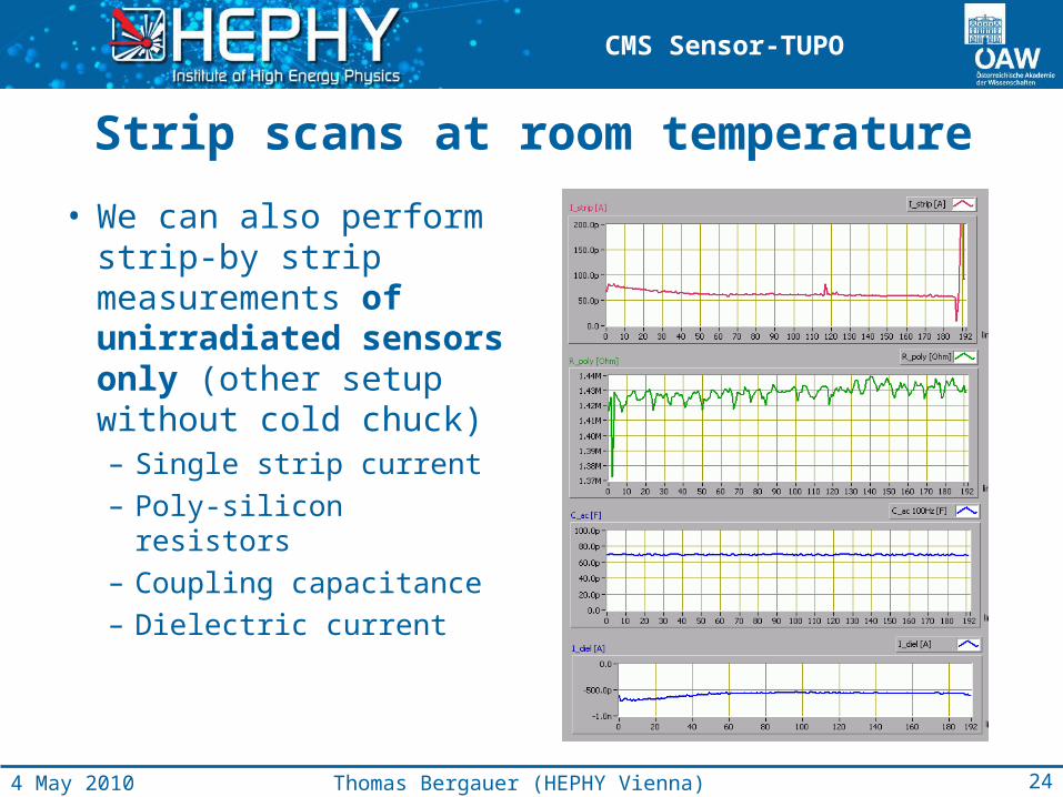
CMS Sensor-TUPO
Strip scans at room temperature
• We can also perform strip-by strip measurements of unirradiated sensors only (other setup without cold chuck)– Single strip current– Poly-silicon resistors– Coupling capacitance– Dielectric current
24Thomas Bergauer (HEPHY Vienna)4 May 2010
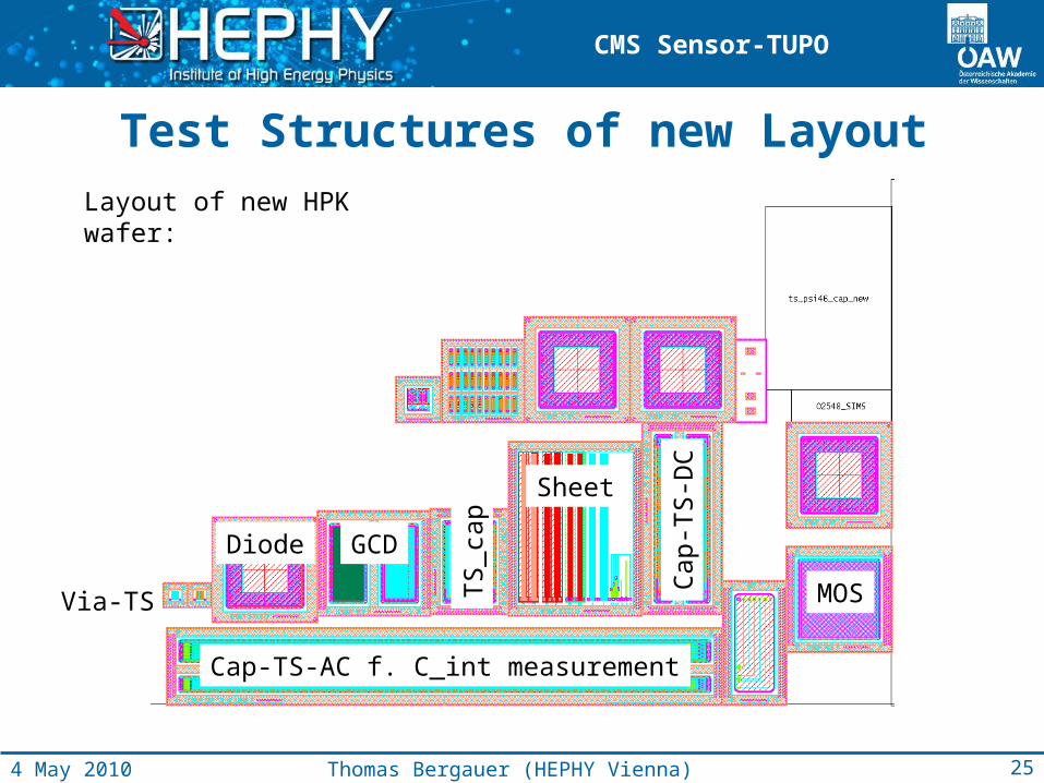
CMS Sensor-TUPO
Test Structures of new LayoutLayout of new HPK wafer:
Diode GCD
TS
_cap
Cap-TS-AC f. C_int measurement
Sheet
MOSVia-TS
Cap
-TS
-DC
25Thomas Bergauer (HEPHY Vienna)4 May 2010
CMS Sensor-TUPO
Manpower / Timing
• Time Estimate for full half moon: 4h– Manual measurements, no
probe-card
• Time estimate with probe-card: 30 minutes– But: effort necessary to
design und buy probe-card
– Large effort to modify setup
– Setup not flexible for other measurements anymore
Available manpower• Technicians
– 0-2 FTE as necessary
• Physicist – 0-2 FTE as necessary
• Students– 0.2 - 1 FTE
26Thomas Bergauer (HEPHY Vienna)4 May 2010
CMS Sensor-TUPO
Planning/Summary
• Currently: We are re-measuring all parameters of irradiated/not irradiated structures that our student gets familiar with it
• Necessary modification of software – improve fits– DB interaction (once TrackerDB stuff gets settled)
• We will perform n-irradiation in our own reactor for testing purposes in near future
• We are ready for the delivery from HPK
27Thomas Bergauer (HEPHY Vienna)4 May 2010
CMS Sensor-TUPO
THE ENDBackup slides follow
28Markus Friedl (HEPHY Vienna)20 October 2009
CMS Sensor-TUPO
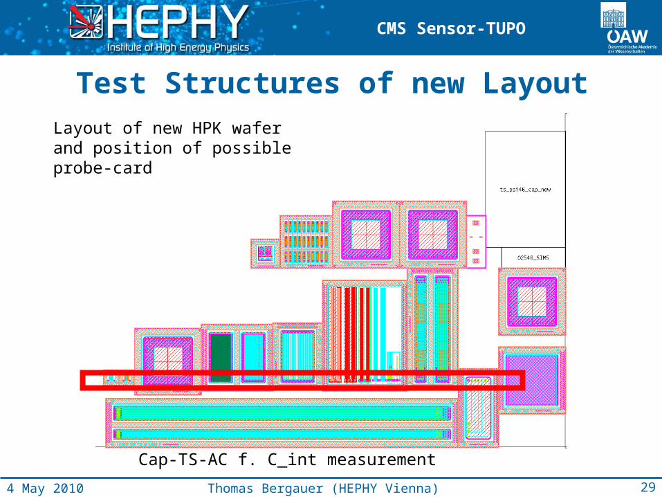
Test Structures of new LayoutLayout of new HPK wafer and position of possible probe-card
Cap-TS-AC f. C_int measurement
29Thomas Bergauer (HEPHY Vienna)4 May 2010