Embed Size (px)
Citation preview
Testing the Physical Layer for EtherNet/IP
NI03
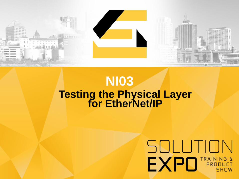
Common Network
Infrastructure Assets
2
Copper and fiber cable certification and troubleshooting
Communication networks testing
Datacom Installers Enterprise IT Network Engineers
Distributed and handheld LAN and WAN test and
analysis solutions
Control & Automation Engineers
Networks solutions from deployment,
to troubleshooting, testing, verification
3
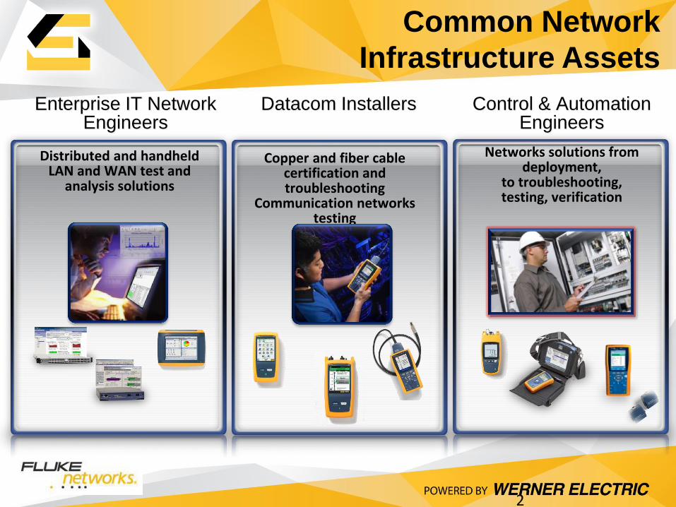
Will Your Network Perform?
The Physical Layer is much more than cable .. 3 keys to
succeed
• Vision: Clear understanding of importance of physical
infrastructure
• Strategy: Understand best practices and pitfalls to avoid
• Execution: Implement and certify robust solutions for each
level of the architecture
Vision Strategy Execution
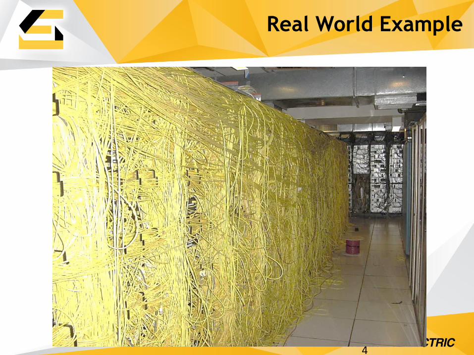
Real World Example
4

Real World Example
5

Real World Example
6
7
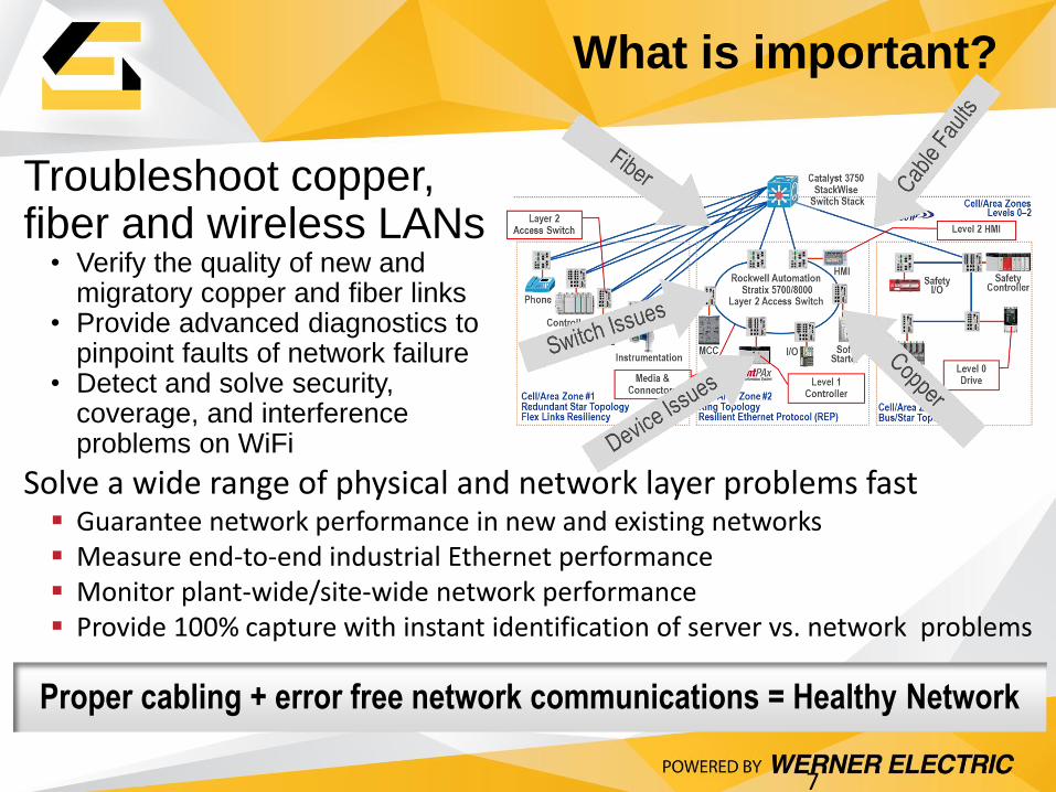
What is important?
Troubleshoot copper, fiber and wireless LANs
• Verify the quality of new and migratory copper and fiber links
• Provide advanced diagnostics to pinpoint faults of network failure
• Detect and solve security, coverage, and interference problems on WiFi
Proper cabling + error free network communications = Healthy Network
Solve a wide range of physical and network layer problems fast Guarantee network performance in new and existing networks Measure end-to-end industrial Ethernet performance Monitor plant-wide/site-wide network performance Provide 100% capture with instant identification of server vs. network problems
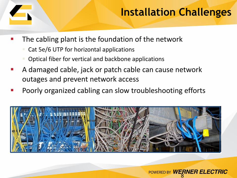
Installation Challenges
The cabling plant is the foundation of the network Cat 5e/6 UTP for horizontal applications
Optical fiber for vertical and backbone applications
A damaged cable, jack or patch cable can cause network outages and prevent network access
Poorly organized cabling can slow troubleshooting efforts
8
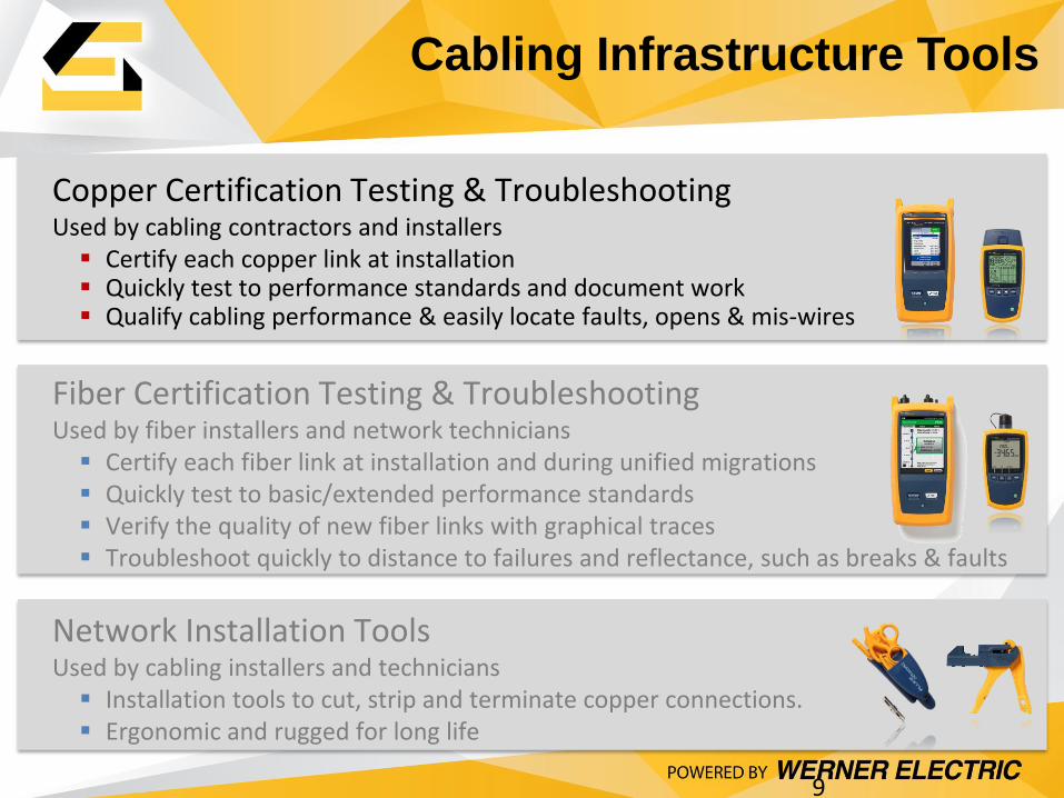
Cabling Infrastructure Tools
9
Fiber Certification Testing & Troubleshooting Used by fiber installers and network technicians Certify each fiber link at installation and during unified migrations Quickly test to basic/extended performance standards Verify the quality of new fiber links with graphical traces Troubleshoot quickly to distance to failures and reflectance, such as breaks & faults
Copper Certification Testing & Troubleshooting Used by cabling contractors and installers Certify each copper link at installation Quickly test to performance standards and document work Qualify cabling performance & easily locate faults, opens & mis-wires
Network Installation Tools Used by cabling installers and technicians Installation tools to cut, strip and terminate copper connections. Ergonomic and rugged for long life
10
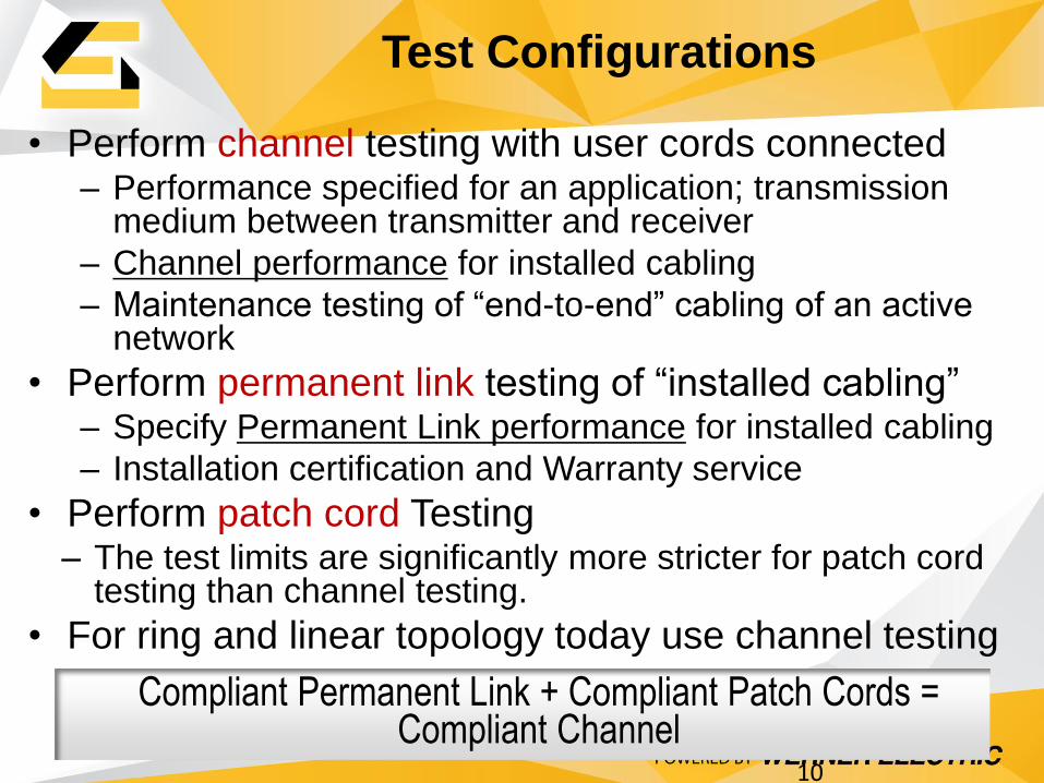
Test Configurations
• Perform channel testing with user cords connected – Performance specified for an application; transmission
medium between transmitter and receiver
– Channel performance for installed cabling
– Maintenance testing of “end-to-end” cabling of an active network
• Perform permanent link testing of “installed cabling” – Specify Permanent Link performance for installed cabling
– Installation certification and Warranty service
• Perform patch cord Testing – The test limits are significantly more stricter for patch cord
testing than channel testing.
• For ring and linear topology today use channel testing Compliant Permanent Link + Compliant Patch Cords =
Compliant Channel

Verification
A verification tester performs
a simple Wire Map test
checking for continuity and
length.
The MicroScanner 2 will give
the distance to an open or
short.
Links looks good……….
11
Qualification
12
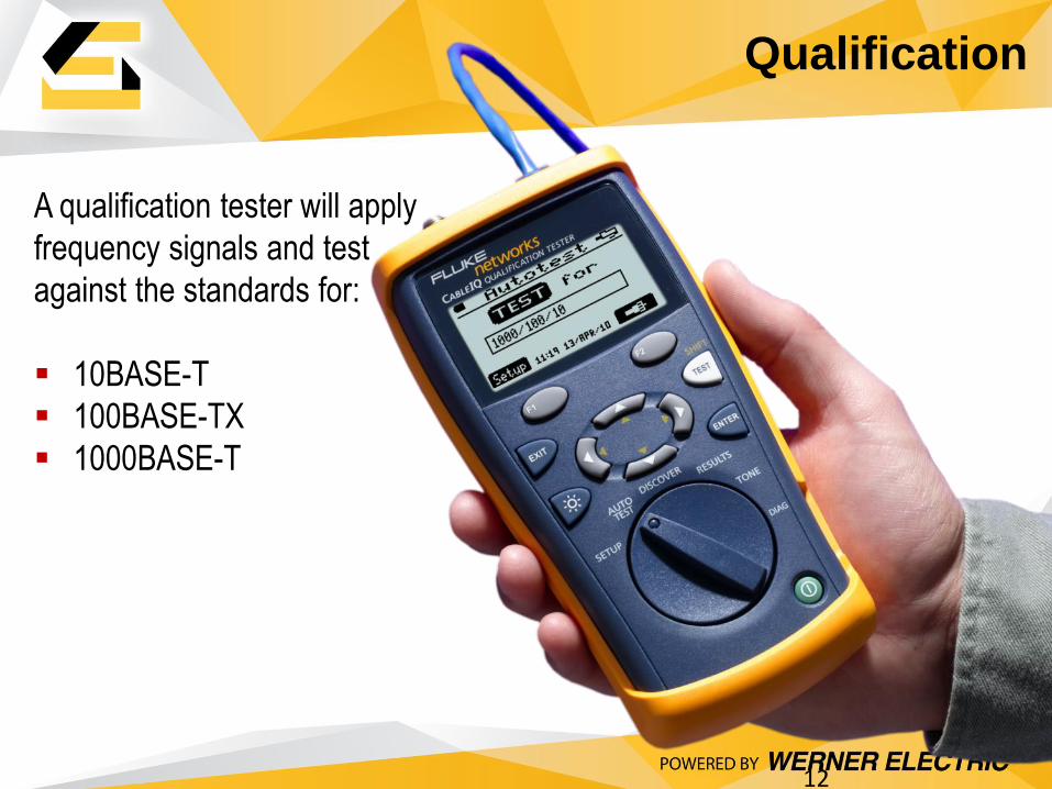
A qualification tester will apply
frequency signals and test
against the standards for:
10BASE-T
100BASE-TX
1000BASE-T

A qualification tester will apply
frequency signals and test
against the standards for:
10BASE-T
100BASE-TX
1000BASE-T
Let’s dig in and see where the
failure is…….
Qualification
13
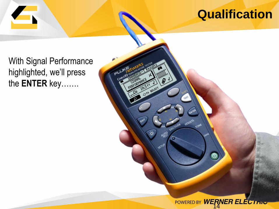
With Signal Performance
highlighted, we’ll press
the ENTER key…….
Qualification
14
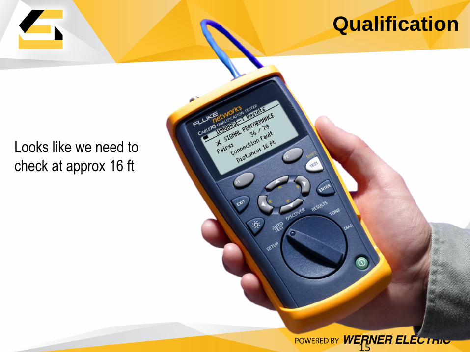
Looks like we need to
check at approx 16 ft
Qualification
15

Copper Cable Certification
Channel Permanent Link
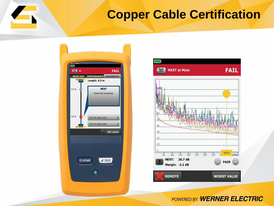
Copper Cable Certification
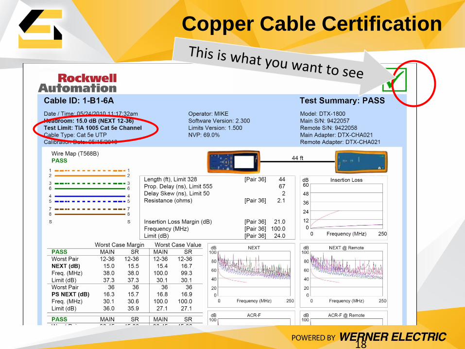
18
Copper Cable Certification
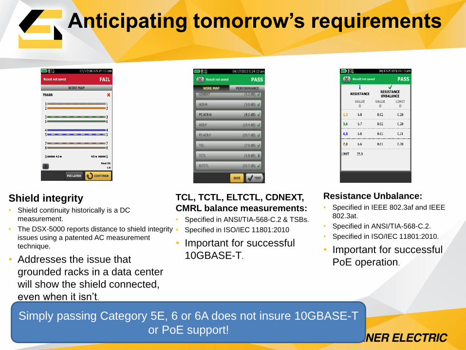
Shield integrity • Shield continuity historically is a DC
measurement.
• The DSX-5000 reports distance to shield integrity
issues using a patented AC measurement
technique.
• Addresses the issue that
grounded racks in a data center
will show the shield connected,
even when it isn’t.
Anticipating tomorrow’s requirements
Resistance Unbalance:
• Specified in IEEE 802.3af and IEEE
802.3at.
• Specified in ANSI/TIA-568-C.2.
• Specified in ISO/IEC 11801:2010.
• Important for successful
PoE operation.
TCL, TCTL, ELTCTL, CDNEXT,
CMRL balance measurements:
• Specified in ANSI/TIA-568-C.2 & TSBs.
• Specified in ISO/IEC 11801:2010
• Important for successful
10GBASE-T.
Simply passing Category 5E, 6 or 6A does not insure 10GBASE-T
or PoE support!
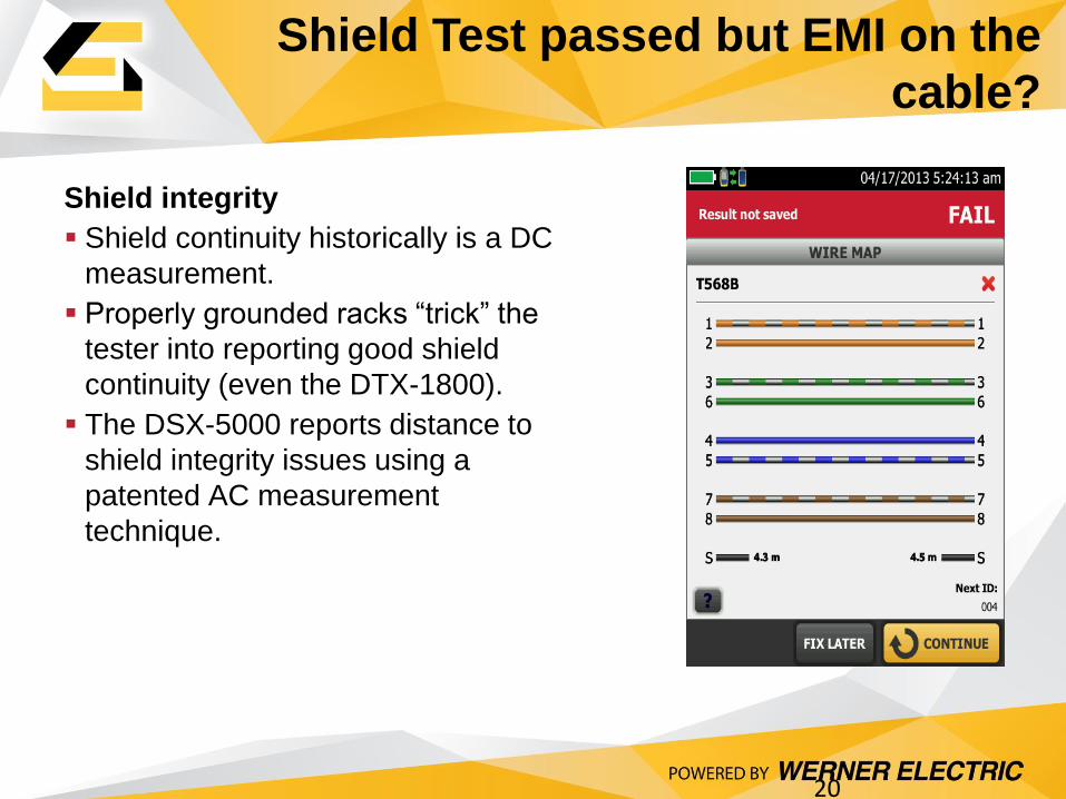
Shield Test passed but EMI on the
cable?
20
Shield integrity
Shield continuity historically is a DC
measurement.
Properly grounded racks “trick” the
tester into reporting good shield
continuity (even the DTX-1800).
The DSX-5000 reports distance to
shield integrity issues using a
patented AC measurement
technique.
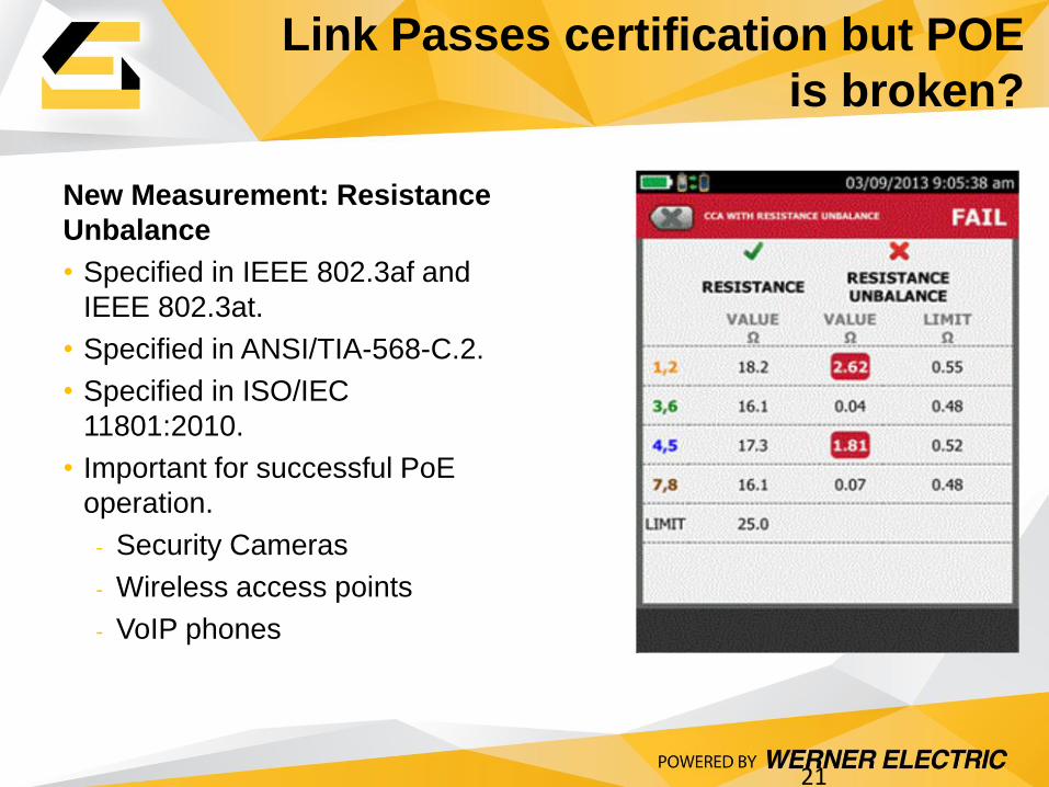
Link Passes certification but POE
is broken?
21
New Measurement: Resistance
Unbalance
• Specified in IEEE 802.3af and
IEEE 802.3at.
• Specified in ANSI/TIA-568-C.2.
• Specified in ISO/IEC
11801:2010.
• Important for successful PoE
operation.
- Security Cameras
- Wireless access points
- VoIP phones
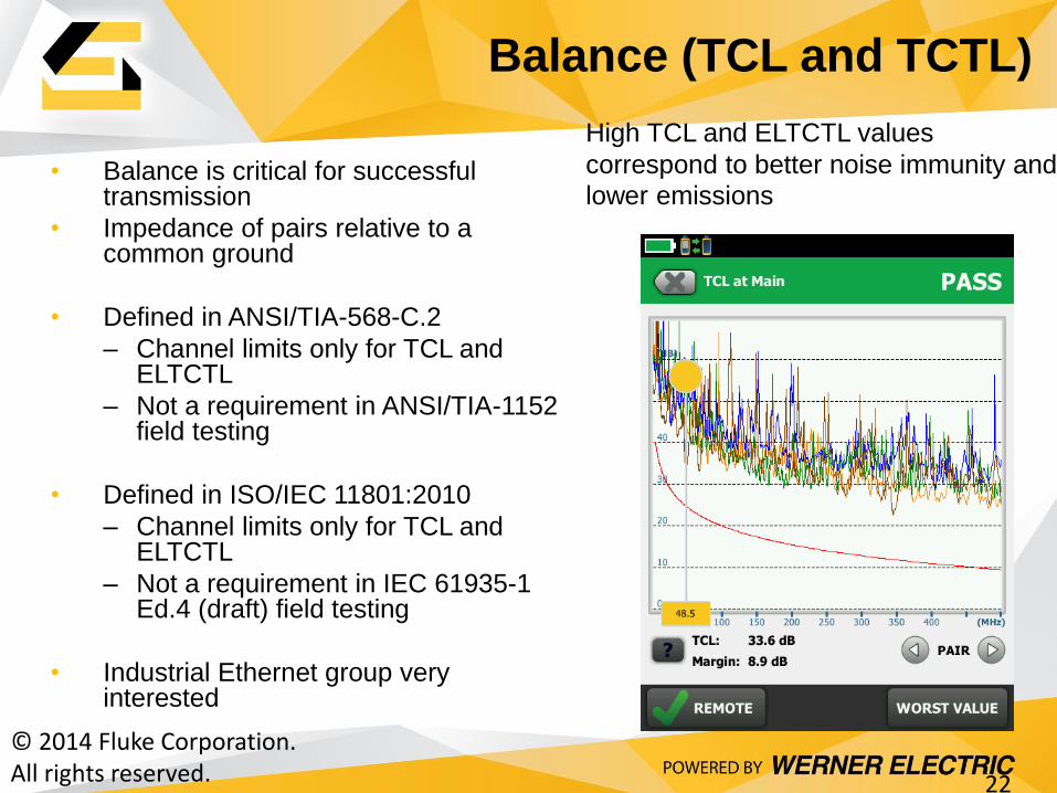
• Balance is critical for successful transmission
• Impedance of pairs relative to a common ground
• Defined in ANSI/TIA-568-C.2
– Channel limits only for TCL and ELTCTL
– Not a requirement in ANSI/TIA-1152 field testing
• Defined in ISO/IEC 11801:2010
– Channel limits only for TCL and ELTCTL
– Not a requirement in IEC 61935-1 Ed.4 (draft) field testing
• Industrial Ethernet group very interested
Balance (TCL and TCTL)
© 2014 Fluke Corporation. All rights reserved. 22
High TCL and ELTCTL values
correspond to better noise immunity and
lower emissions
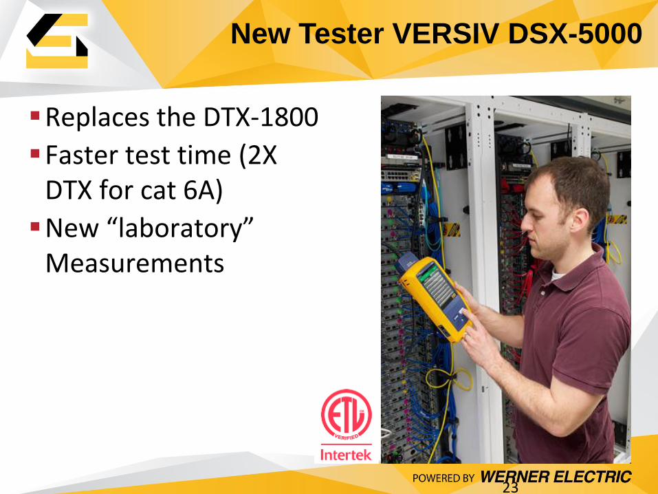
New Tester VERSIV DSX-5000
23
Replaces the DTX-1800
Faster test time (2X DTX for cat 6A)
New “laboratory” Measurements
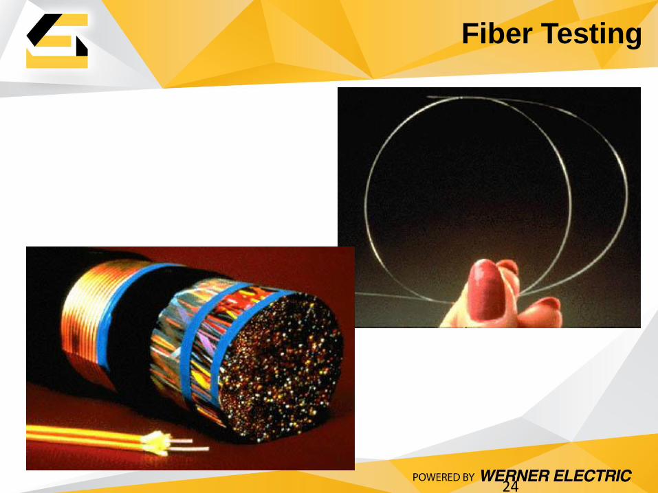
Fiber Testing
24

Cabling Infrastructure Tools
25
Fiber Certification Testing & Troubleshooting Used by fiber installers and network technicians Certify each fiber link at installation and during unified migrations Quickly test to basic/extended performance standards Verify the quality of new fiber links with graphical traces Troubleshoot quickly to distance to failures and reflectance, such as breaks & faults
Copper Certification Testing & Troubleshooting Used by cabling contractors and installers Certify each copper link at installation Quickly test to performance standards and document work Qualify cabling performance & easily locate faults, opens & mis-wires
Network Installation Tools Used by cabling installers and technicians Installation tools to cut, strip and terminate copper connections. Ergonomic and rugged for long life
26
Factors Affecting Optical Fiber
Performance
• Signal strength (measurement of link loss) – The signal must have a minimum strength to be
detected and decoded by receiver
– For optical signaling, the receiver must be able to distinguish a “lights on” from a “light off” symbol
– “Applications” specify Channel Loss
• Disturbances to signal transmission – Signal dispersion
• Dispersion characteristics determine the distance over which a specific data rate can be supported
• Major cause of Inter Symbol Interference (ISI)
– Reflections (Return Loss) • Reflections contribute to ISI
27
Sources of Signal Loss
• Intrinsic loss of the fiber optic cable – Defined by physics and manufacturing process
• Raleigh Scattering
• Water Peak Absorption (except for zero water peak fiber)
– Increases with distance (length of link)
– Affected by bends
• Connections – Mechanical:
• Core alignment, dirt on end face, reflections due to air gap
– Fusion splices: core alignment
– Numerical Aperture Mismatch in Multimode Fibers
Problem #1: Dirt on end-face of fiber

28
#1 Problem: Dirt(!)
• Contaminated connector end-faces: Leading
cause of fiber link failures
• Particles of dust and debris trapped between
fiber end-faces cause signal loss, back
reflection, and damaged equipment
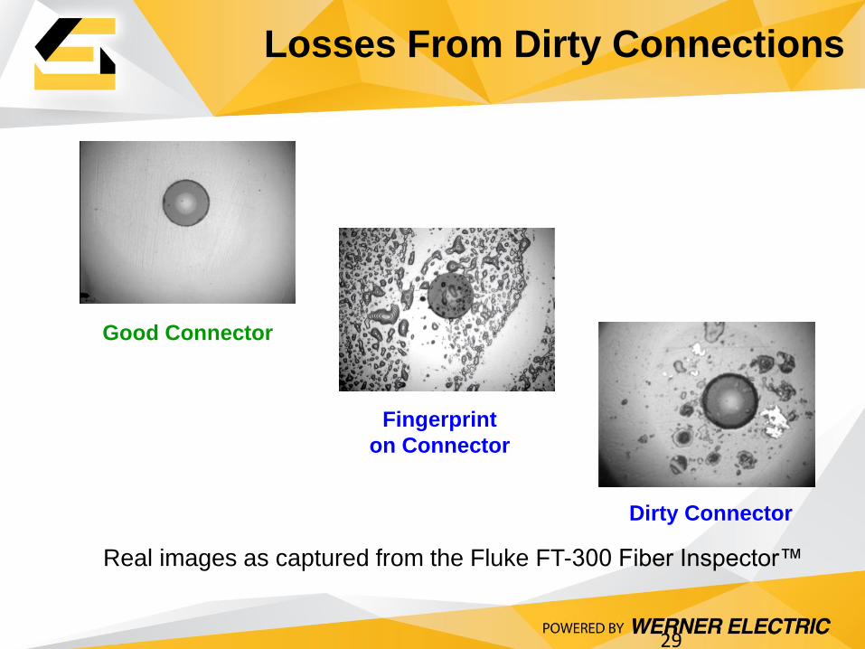
Good Connector
Fingerprint
on Connector
Dirty Connector
Losses From Dirty Connections
29
Real images as captured from the Fluke FT-300 Fiber Inspector™
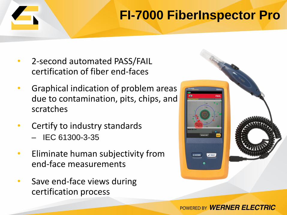
• 2-second automated PASS/FAIL certification of fiber end-faces
• Graphical indication of problem areas due to contamination, pits, chips, and scratches
• Certify to industry standards – IEC 61300-3-35
• Eliminate human subjectivity from end-face measurements
• Save end-face views during certification process
FI-7000 FiberInspector Pro
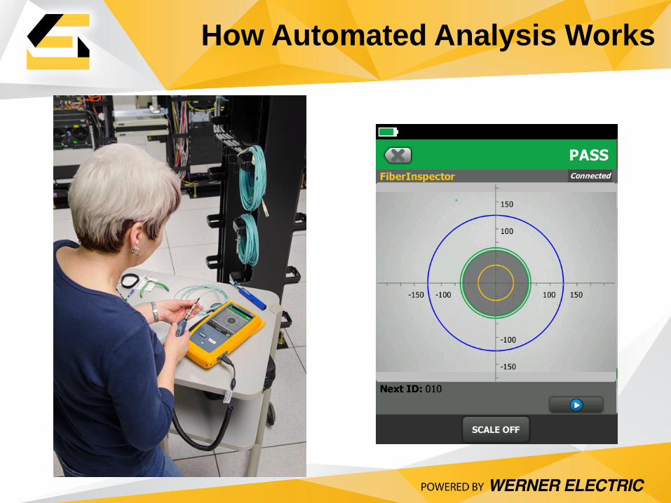
How Automated Analysis Works
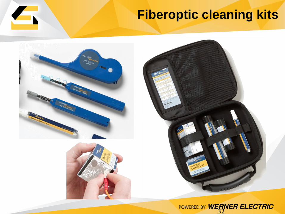
Fiberoptic cleaning kits
32

33
Smart Testing & Troubleshooting
• Eliminate common problems with good practices during installation and maintenance
– Verify continuity, polarity, adequate end-face condition with basic tools to ensure best termination and installation practices
• Perform complete cable certification per TIA 568C
– Basic certification (Tier 1): Length/Loss
– Extended certification (Tier 2): OTDR trace analysis
34
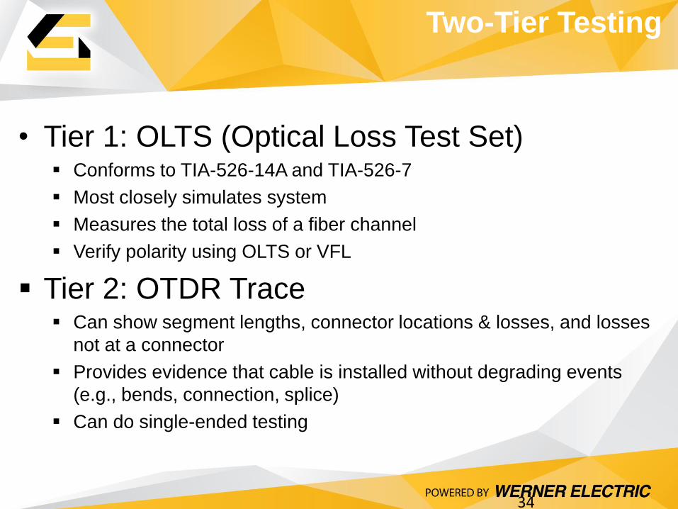
Two-Tier Testing
• Tier 1: OLTS (Optical Loss Test Set) Conforms to TIA-526-14A and TIA-526-7
Most closely simulates system
Measures the total loss of a fiber channel
Verify polarity using OLTS or VFL
Tier 2: OTDR Trace Can show segment lengths, connector locations & losses, and losses
not at a connector
Provides evidence that cable is installed without degrading events
(e.g., bends, connection, splice)
Can do single-ended testing

Multimode Performance at 850 nm
35
Fiber Type Bandwidth 1000BASE-SX 10GBASE-SR
Core size
(μm)
MHz•Km Length
(m)
Loss
(dB)
Length
(m)
Loss
(dB)
OM1 62.5 200 275 2.3 33 2.4
OM2 50 500 550 3.6 82 2.3
OM3 50 2000 1000 3.6 300 2.6
OM4 50 4700 1040 3.6 550 2.6
Note: 40GBASE-SR4 and 100GBASE-SR10 require parallel
optical channels
40GBASE-SR4
100GBASE-SR10
Length
(m)
Loss
(dB)
- -
- -
100 1.9
150 1.5
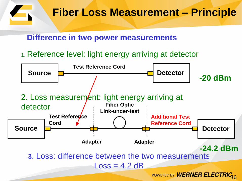
Fiber Loss Measurement – Principle
36
1. Reference level: light energy arriving at detector
Test Reference Cord
Source Detector
Difference in two power measurements
2. Loss measurement: light energy arriving at
detector Additional Test
Reference Cord
Adapter Adapter
Test Reference
Cord
Fiber Optic
Link-under-test
Source Detector
3. Loss: difference between the two measurements
Loss = 4.2 dB
-20 dBm
-24.2 dBm

No More Mistakes with the Reference Wizard • Shows you how to set a fiber
reference.
• Verifies the test reference cords.
• Saves the test reference cords verification. • Critical for confirming the
accuracy of loss measurements
Loss Testing with VERSIV
CertiFiber Pro
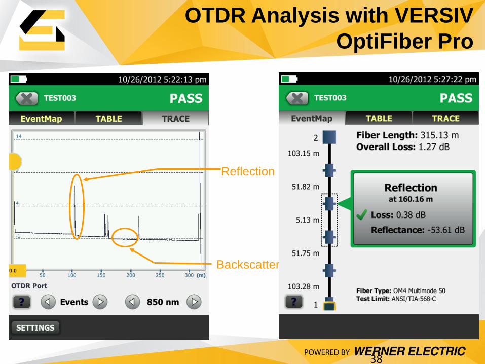
OTDR Analysis with VERSIV
OptiFiber Pro
38
Backscatter
Reflection
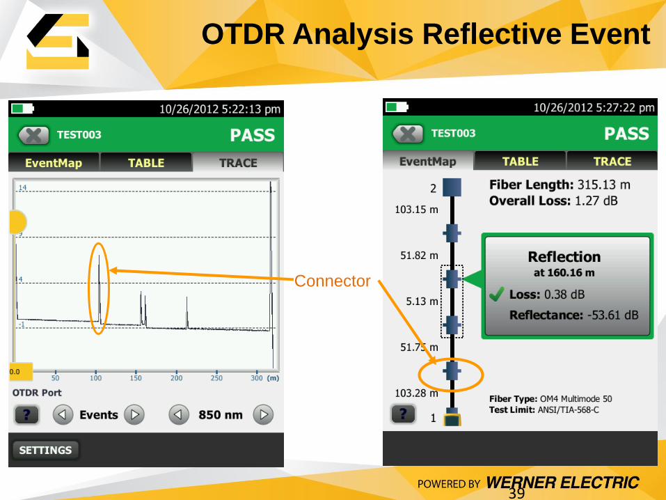
OTDR Analysis Reflective Event
39
Connector

OTDR Analysis Loss Event
40
Non-reflective event
Splice or severe bend
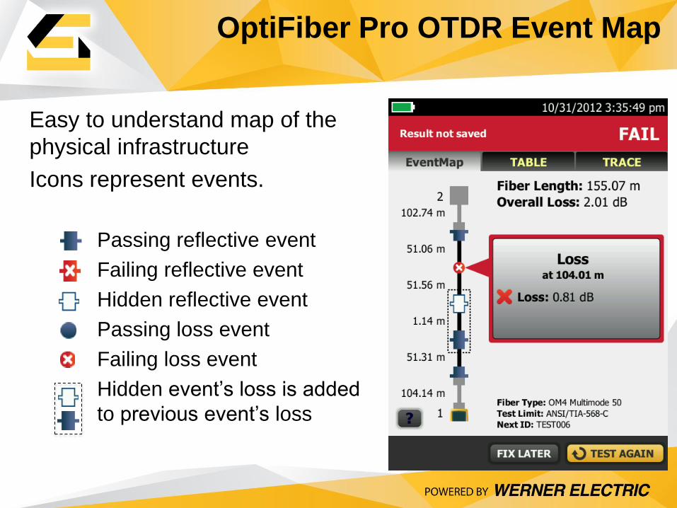
Easy to understand map of the
physical infrastructure
Icons represent events.
Passing reflective event
Failing reflective event
Hidden reflective event
Passing loss event
Failing loss event
Hidden event’s loss is added
to previous event’s loss
OptiFiber Pro OTDR Event Map

42
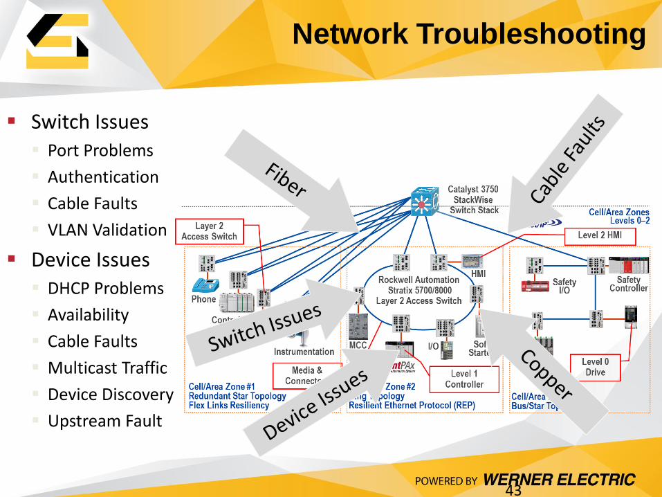
Network Troubleshooting
43
Switch Issues Port Problems
Authentication
Cable Faults
VLAN Validation
Device Issues DHCP Problems
Availability
Cable Faults
Multicast Traffic
Device Discovery
Upstream Fault

Real World Example
44
RouterLB .
IBM Host
192.168.14.192
/26
192.168.15.0
/26
192.168.15.64
/26
192.168.15.128
/26
192.168.14.20
192.168.14.21
192.168.14.22
192.168.14.23
192.168.14.24
192.168.14.25
192.168.14.26
192.168.14.27
192.168.15.11
192.168.15.12
192.168.15.13
192.168.15.14
192.168.15.15
192.168.15.16
192.168.15.17
192.168.15.18
192.168.15.75
192.168.15.76
192.168.15.77
192.168.15.78
192.168.15.79
192.168.15.80
192.168.15.81
192.168.15.82
192.168.16.0
/26
VIP=192.168.15.19
192.168.16.11
192.168.16.12
.192.16815.87
192.168.15.88
* local VLAN traffic
to APP servers
AC
ME
Ap
p
Se
rve
r a
gg
reg
atio
n
We
b O
uts
ide
Se
rve
r
Ag
gre
ga
tio
n
192.168.14.11
TCP 443
TCP 5000-5100
LB .
LB .
LB .
TCP 8080
VIP = outside VLAN query
SQL = server to server query
ACME DB-VIP Server aggregation
We
b In
sid
e
Clie
nt A
gg
reg
atio
n
* GW connection to
IBM Host using
SCON
ACME WEB-VIP-ACE
ACME WEB/Outside ACME WEB/InsideACME APP2
192.168.15.84
192.168.15.85
172.27.15.90
ACME APP1
ACME APP3
ACME CL1
ACME MainFrame
ACME WEB-Portal
TCP 443
TCP 5000-5100
Public Web
ACME App
ACME App
IntAuth
Web URL (Agg)
ACME CL2
ACME CL3
VIP=192.168.15.147
SQL=192.168.15.148
192.168.15.139
192.168.15.140
VIP=192.168.15.151
SQL=192.168.15.152
192.168.15.145
192.168.15.146
TCP 135Windows Svcs
192.168.3.51
TCP 135
Windows Svcs
TCP 445
Windows Svcs
TCP 445Windows Svcs
TCP 2255
Database
TCP 1732Database
192.168.160.102
TCP 3040Mainframe
192.168.160.102
MainframeTCP 1414, 1515, 1815
TCP 88Authentication
DC
Web Portal NAT
192.168.16.71
VIP=192.168.15.149
SQL=192.168.15.150
192.168.15.142
192.168.15.143
TCP 1876Database
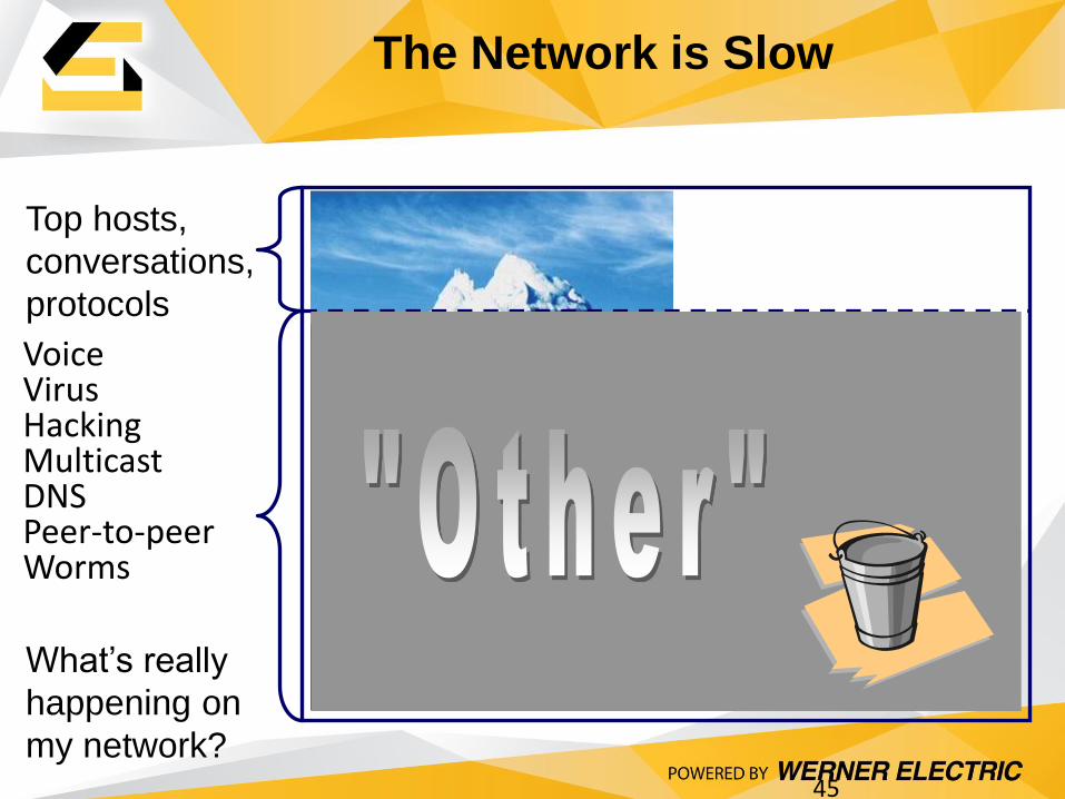
The Network is Slow
45
Voice Virus Hacking Multicast DNS Peer-to-peer Worms
Top hosts,
conversations,
protocols
What’s really
happening on
my network?
46
Best Practices – Processes
Planning & Documenting
• Standards
• Documentation & baselines
• Have a documented plan - what, who, and how
Problem Prevention
• Prevent problems before they happen
• Do’s and Don’ts for end-users
• Testing and certification
Early Problem Detection
• Network monitoring
• Periodic audits (update baselines)
• Centralized help desk
Follow a troubleshooting methodology

47
Troubleshooting Methodology
Step 1 - Collect Information
Step 2 - Localize & Isolate the Problem
Step 3 - Correct the Problem
Step 4 - Verify Problem Resolution
Step 5 - Document What You Did
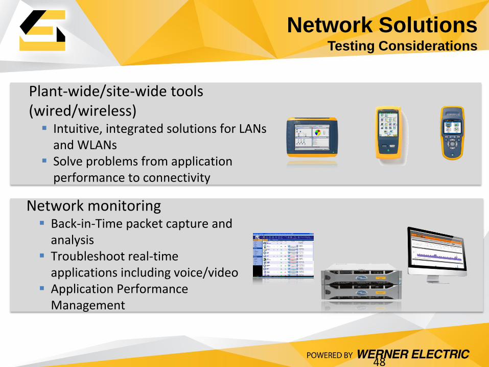
Network Solutions Testing Considerations
48
Plant-wide/site-wide tools (wired/wireless) Intuitive, integrated solutions for LANs
and WLANs Solve problems from application
performance to connectivity
Network monitoring Back-in-Time packet capture and
analysis Troubleshoot real-time
applications including voice/video Application Performance
Management
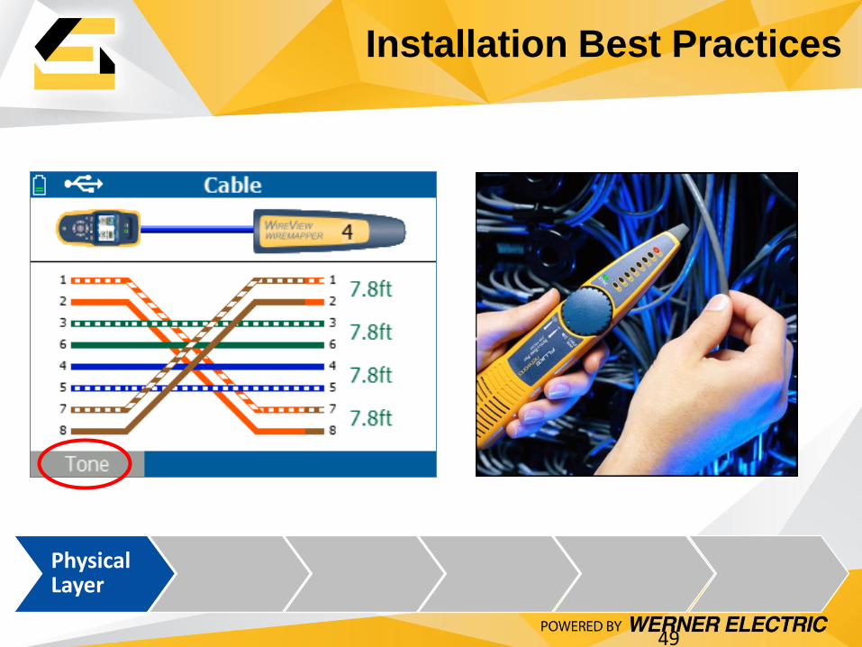
Physical Layer
Installation Best Practices
49

Check for 802.3af PoE
Check for duplex issues due to auto-negotiation configurations
Physical Layer
Power & Link
Installation Best Practices
50
Physical Layer
Power & Link
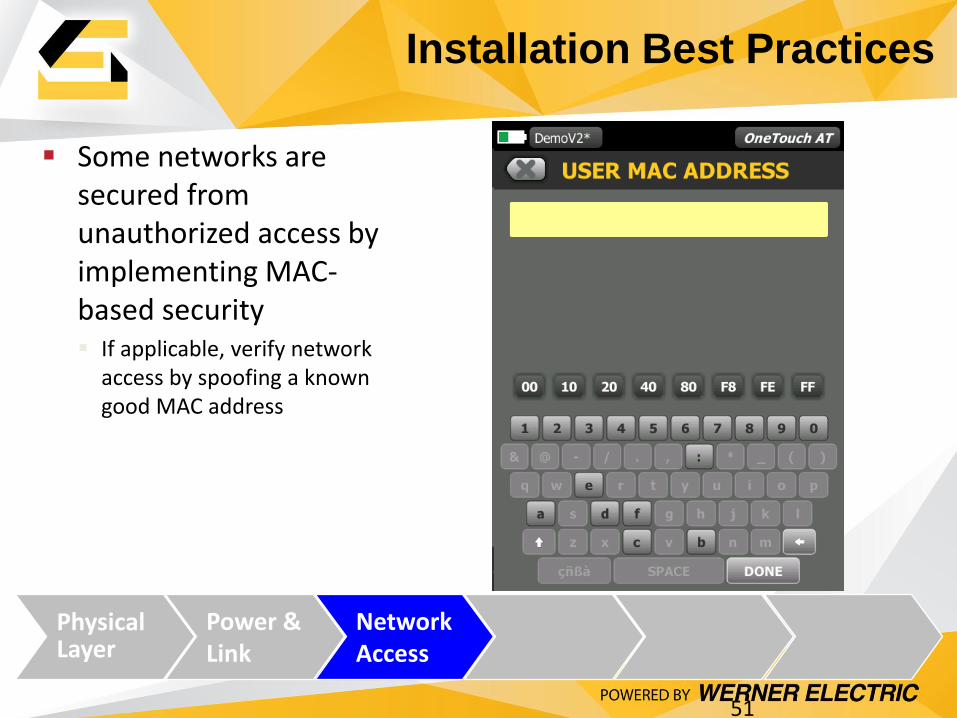
Network Access
Some networks are secured from unauthorized access by implementing MAC-based security If applicable, verify network
access by spoofing a known good MAC address
Installation Best Practices
51

Verify the availability of key network services
Services are listed for each device
Physical Layer
Power & Link
Network Access
Network Services
Installation Best Practices
52

Physical Layer
Power & Link
Network Access
Network Services
Config
Verify that devices are correctly configured Addresses, switch
information, properties, VLAN
OneTouch AT’s automated SNMP-based discovery provides vision into network and device configurations
53
Installation Best Practices
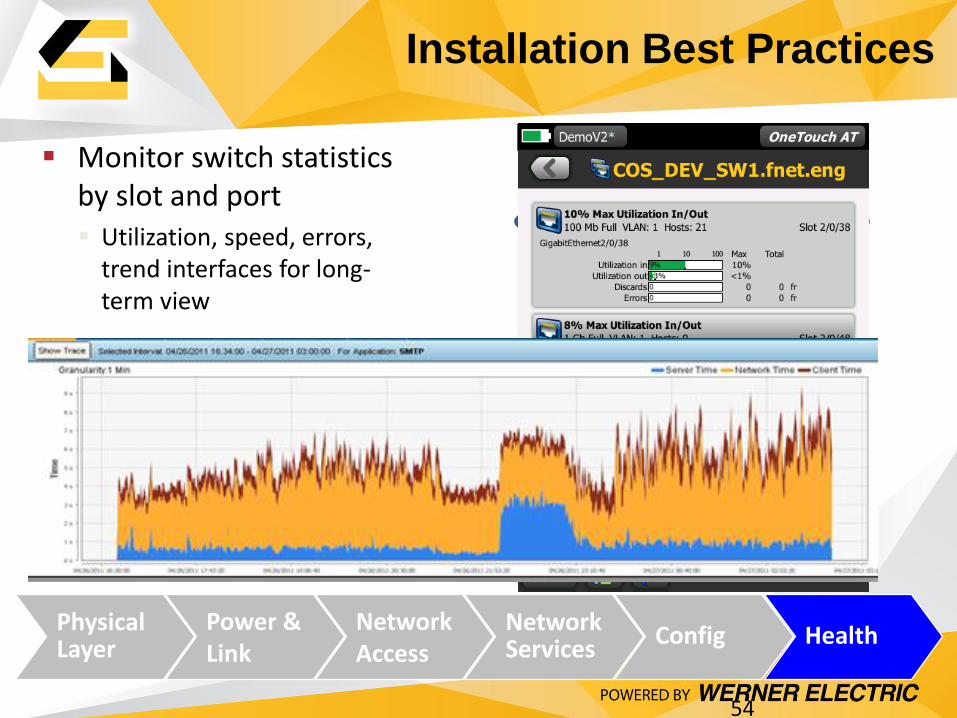
Monitor switch statistics by slot and port Utilization, speed, errors,
trend interfaces for long-term view
Physical Layer
Power & Link
Network Access
Network Services
Config Health
Installation Best Practices
54
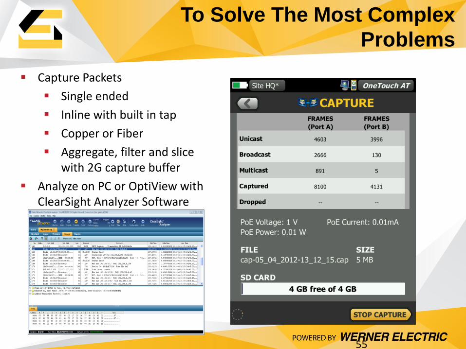
Capture Packets
Single ended
Inline with built in tap
Copper or Fiber
Aggregate, filter and slice with 2G capture buffer
Analyze on PC or OptiView with ClearSight Analyzer Software
To Solve The Most Complex
Problems
55
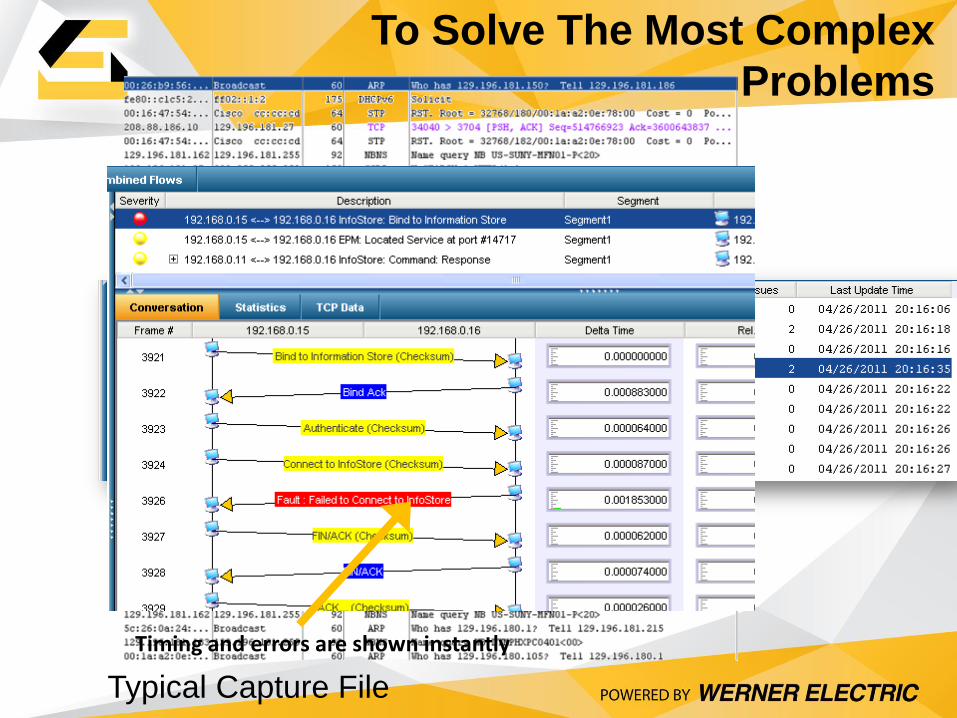
To Solve The Most Complex
Problems
Timing and errors are shown instantly
Typical Capture File
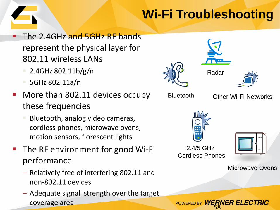
The 2.4GHz and 5GHz RF bands represent the physical layer for 802.11 wireless LANs 2.4GHz 802.11b/g/n
5GHz 802.11a/n
More than 802.11 devices occupy these frequencies Bluetooth, analog video cameras,
cordless phones, microwave ovens, motion sensors, florescent lights
The RF environment for good Wi-Fi performance – Relatively free of interfering 802.11 and
non-802.11 devices
– Adequate signal strength over the target coverage area
Bluetooth Other Wi-Fi Networks
Microwave Ovens
2.4/5 GHz
Cordless Phones
Radar
Wi-Fi Troubleshooting
58
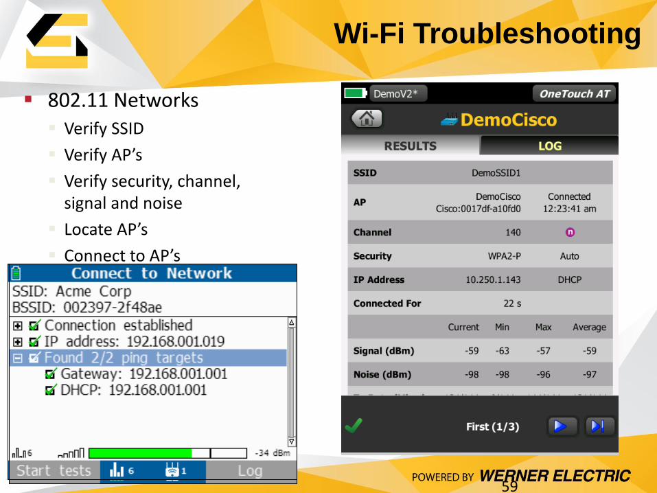
802.11 Networks Verify SSID
Verify AP’s
Verify security, channel, signal and noise
Locate AP’s
Connect to AP’s
Wi-Fi Troubleshooting
59
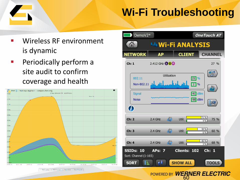
Wireless RF environment is dynamic
Periodically perform a site audit to confirm coverage and health
Wi-Fi Troubleshooting
60
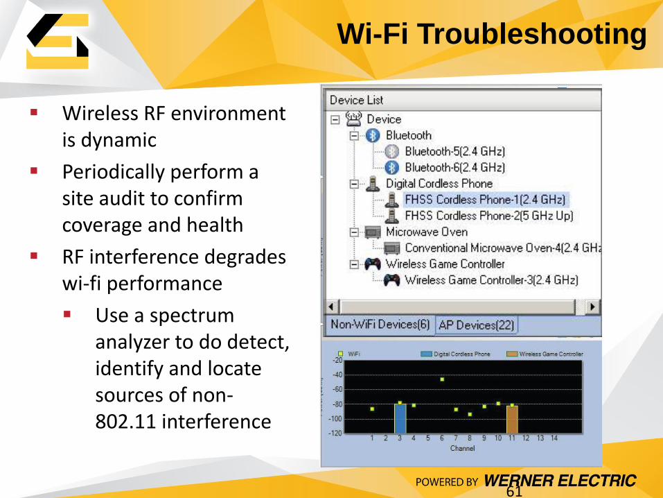
Wireless RF environment is dynamic
Periodically perform a site audit to confirm coverage and health
RF interference degrades wi-fi performance
Use a spectrum analyzer to do detect, identify and locate sources of non-802.11 interference
Wi-Fi Troubleshooting
61

Testing the Physical Layer for
EtherNet/IP
62
Planning and installing physical infrastructure based on standards, best practices and reference architectures will result in higher availability, integrity and performance
Need help? Leverage your partners:
Rockwell Automation Network and Security Services
Panduit Certified Installers
Fluke Networks’ training
Vision Strategy Execution
Because Network
Infrastructure Matters!!

Testing the Physical Layer for
EtherNet/IP
63
Planning and installing physical infrastructure based on standards, best practices and reference architectures will result in higher availability, integrity and performance
Need help? Leverage your partners:
Rockwell Automation Network and Security Services
Panduit Certified Installers
Fluke Networks’ training
Vision Strategy Execution
64
Additional Material
• Fluke Networks Websites
– www.flukenetworks.com
– www.flukenetworks.com\industrial
– www.flukenetworks.com\knowledgebase