Embed Size (px)
Citation preview

Testo 552 - Vacuumstick
Instruction manual

Content
Content 1 Safety and waste disposal ................................................................... 1
1.1 About this document ............................................................................. 1 1.2 Safety .................................................................................................... 1 1.3 Waste disposal ...................................................................................... 2
2 Technical data ..................................................................................... 3 3 Description of the instrument ............................................................... 4
3.1 Use ........................................................................................................ 4 3.2 Instrument overview .............................................................................. 4 3.3 Displays overview .................................................................................. 5 3.4 Control keys overview ........................................................................... 6 3.5 Connection options overview ................................................................ 7
4 Operation ............................................................................................. 8 4.1 Connecting ............................................................................................ 8 4.2 Switching instrument on and off ............................................................ 9 4.3 Switching background illumination on and off ...................................... 9 4.4 Setting units and AutoOff ...................................................................... 9 4.5 Displaying temperature values ............................................................ 12 4.6 Field calibration ................................................................................... 13 4.7 Operating as a probe on the testo 570 ................................................ 13
5 Maintenance ...................................................................................... 15 5.1 Changing batteries .............................................................................. 15 5.2 Cleaning the instrument ....................................................................... 15
6 Tips and assistance ........................................................................... 16 6.1 Questions and answers ....................................................................... 16 6.2 Accessories and spare parts ............................................................... 16

1 Safety and waste disposal
1
1 Safety and waste disposal
1.1 About this document • The instruction manual is an integral part of the instrument.
• Keep this document throughout the entire operating life of the instrument.
• Always use the complete original instruction manual.
• Please read this instruction manual through carefully and familiarise yourself with the product before putting it to use.
• Pay particular attention to the safety instructions and warning advice in order to prevent injury and damage to the product.
1.2 Safety General safety instructions
• Only operate this instrument in the proper manner, for its intended purpose and within the parameters specified in the technical data.
• Do not apply any force to open the instrument.
• Do not operate the instrument if there are signs of damage at the housing, mains unit or connected cables.
• Always comply with the locally valid safety regulations when carrying out measurements. Dangers may also arise from objects to be measured or the measuring environment.
• Do not store the product together with solvents.
• Do not use any desiccants.
• Only perform maintenance and repair work on this instrument that is described in this documentation. Follow the prescribed steps exactly.
• Use only original spare parts from Testo.
Batteries
• Improper use of batteries may cause the batteries to be destroyed, or lead to injury due to current surges, fire or escaping chemicals.
• Only use the batteries supplied in accordance with the instructions in the instruction manual.
• Do not short-circuit the batteries.
• Do not take the batteries apart and do not modify them.

1 Safety and waste disposal
2
• Do not expose the batteries to heavy impacts, water, fire or temperatures in excess of 60 °C.
• Do not store the batteries in the proximity of metal objects.
• Do not use any leaky or damaged batteries.
• In the event of contact with battery acid: rinse affected areas thoroughly with water, and if necessary consult a doctor.
• Take batteries out of the instrument immediately if they are not functioning properly or if they show signs of overheating.
• Remove all batteries from the instrument if it is to remain unused for a longer period.
Warnings
Always pay attention to any information denoted by the following warnings. Implement the precautionary measures specified!
Display Explanation
WARNING
Indicates possible serious injury.
CAUTION
Indicates possible minor injury.
ATTENTION
Indicates possible damage to equipment.
1.3 Waste disposal • Dispose of faulty rechargeable batteries and spent batteries in accordance
with the valid legal specifications.
• At the end of its useful life, dispose of the instrument via separate collection for electro- and electronic devices. Please observe local regulations concerning waste disposal. Or alternatively return the product to Testo for disposal.
2 Technical data
3
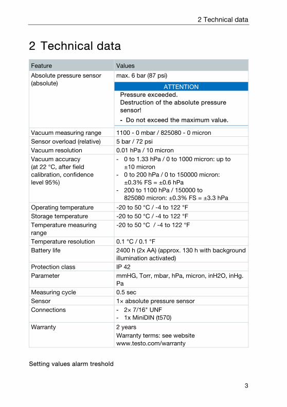
2 Technical data
Feature Values
Absolute pressure sensor (absolute)
max. 6 bar (87 psi)
ATTENTION Pressure exceeded. Destruction of the absolute pressure sensor!
- Do not exceed the maximum value.
Vacuum measuring range 1100 - 0 mbar / 825080 - 0 micron Sensor overload (relative) 5 bar / 72 psi Vacuum resolution 0.01 hPa / 10 micron Vacuum accuracy (at 22 °C, after field calibration, confidence level 95%)
- 0 to 1.33 hPa / 0 to 1000 micron: up to ±10 micron
- 0 to 200 hPa / 0 to 150000 micron: ±0.3% FS = ±0.6 hPa
- 200 to 1100 hPa / 150000 to 825080 micron: ±0.3% FS = ±3.3 hPa
Operating temperature -20 to 50 °C / -4 to 122 °F Storage temperature -20 to 50 °C / -4 to 122 °F Temperature measuring range
-20 to 50 °C / -4 to 122 °F
Temperature resolution 0.1 °C / 0.1 °F Battery life 2400 h (2x AA) (approx. 130 h with background
illumination activated) Protection class IP 42 Parameter mmHG, Torr, mbar, hPa, micron, inH2O, inHg.
Pa Measuring cycle 0.5 sec Sensor 1× absolute pressure sensor Connections - 2× 7/16" UNF
- 1x MiniDIN (t570)
Warranty 2 years Warranty terms: see website www.testo.com/warranty
Setting values alarm treshold

3 Description of the instrument
4
Unit Setting range Resolution
mbar / hPa 0 - 7,5 0,05 micron 0 - 7500 50
3 Description of the instrument
3.1 Use The testo 552 is a digital vacuum gauge for the precise measurement of extremely small pressures in the vacuum range. This allows you to monitor the evacuation (usually during commissioning) of refrigeration systems and heat pumps.
With the testo 552, you can therefore measure the current pressure in a refrigeration system, and thus gather information about the degree of dehumidification and the removal of foreign matter (oils, foreign gases, etc.).
A vacuum gauge is always used in conjunction with a vacuum pump (generates the vacuum). A manifold (analogue or digital) is also often used in order to obtain controlled access to the refrigeration system.
3.2 Instrument overview

3 Description of the instrument
5
Element Function
1 MiniDIN probe socket Cable connection for connecting to the testo 570.
2 Display Displays instrument status icons, measuring units and measuring values.
3 Control keys Instrument operation. 4 Connections 7/16"
UNF, brass Connection of refrigerant hoses, vacuum pump, manifolds, etc..
5 Hook Suspension device 6 Battery compartment Contains two AA batteries.
3.3 Displays overview
Element Function
1 Icon [ ] Displays the remaining battery capacity. >75% >50% >25% <10%
2 Icon [ ] An alarm threshold is set.

3 Description of the instrument
6
Element Function
3 Temperature display - selected, currently measured temperature - Measurement parameter:
TH2O = evaporation temperature of water Tamb = ambient temperature Δt = temperature difference between evaporation temperature of water and ambient temperature
- unit set (°C, °F)
4 Slave Mode Appears when the testo 552 is connected to the testo 570 via a connecting cable and the testo 570 is in Evacuation mode.
5 Pressure display Displays the currently measured pressure, the measurement parameter and the unit set (mmHG, Torr, mbar, hPa, micron, inH2O, inHg).
3.4 Control keys overview
Element Function
1 - Switches to the settings. - Switches between the set-up options.
2 Switches the display illumination on or off. 3 Switches the instrument on or off. 4 - Switches between the temperature displays.
- Navigates in the Set menu.

3 Description of the instrument
7
3.5 Connection options overview
In regard to the following connection options, the testo 570 is used to represent any manifold and can use the testo 552 as a probe via a MiniDIN connecting cable (see Option 2).
Option 1 (recommended)
The testo 552 is connected at the point that is furthest from the vacuum pump. This ensures that a sufficiently deep vacuum is generated throughout the system in order to remove any moisture or foreign gases that may be present.
Option 2
Option 3

4 Operation
8
Option 4
Option 5
4 Operation
4.1 Connecting
Always use refrigerant hoses that are specifically intended for evacuations.
1 - Remove sealing caps.
- Connect the testo 552 to the circuit.

4 Operation
9
4.2 Switching instrument on and off 1 - Press .
The instrument switches on or off.
4.3 Switching background illumination on and off
1 - Switch the instrument on.
- Press .
The background illumination switches on or off.
4.4 Setting units and AutoOff
The set-up menu must always be completely navigated through, even if only one parameter needs to be changed.
4 Operation
10
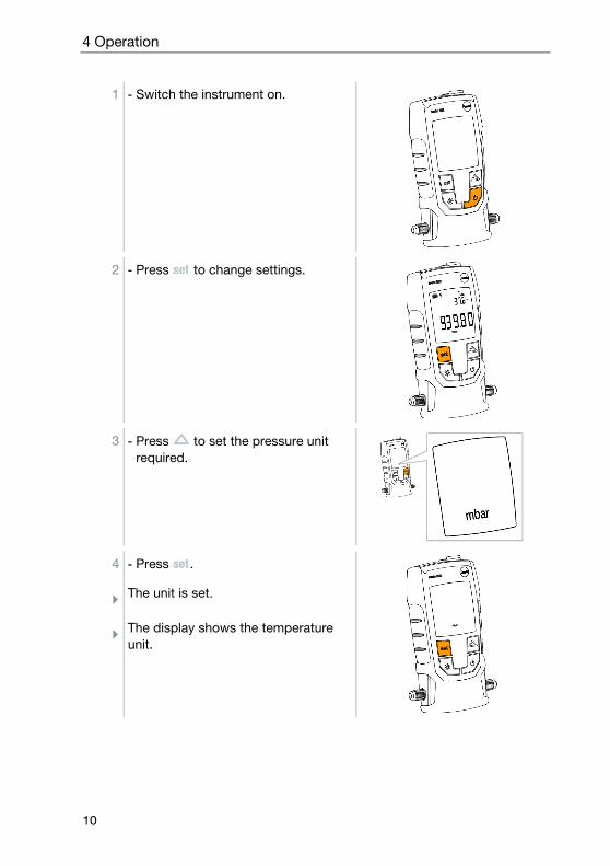
1 - Switch the instrument on.
2 - Press to change settings.
3 - Press to set the pressure unit required.
4 - Press .
The unit is set.
The display shows the temperature unit.
4 Operation
11
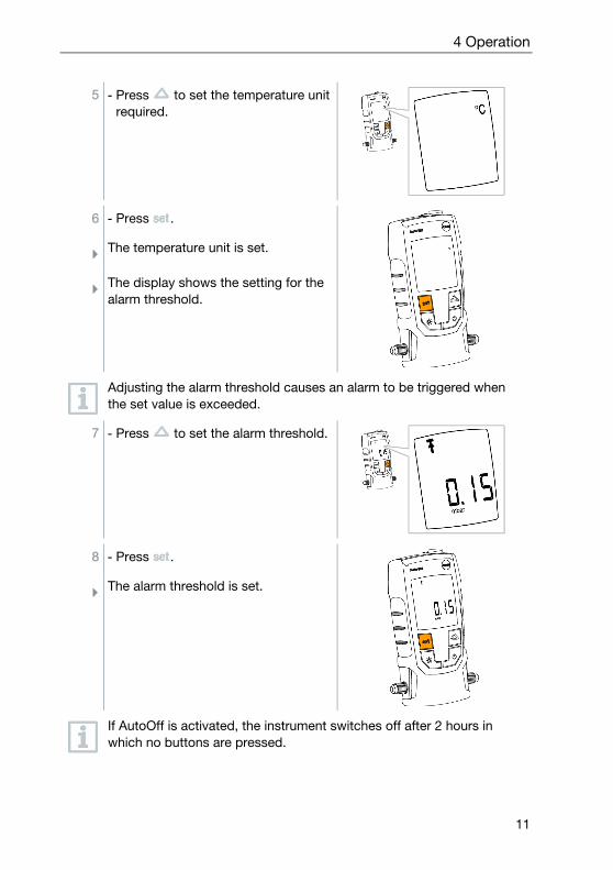
5 - Press to set the temperature unit required.
6 - Press .
The temperature unit is set.
The display shows the setting for the alarm threshold.
Adjusting the alarm threshold causes an alarm to be triggered when the set value is exceeded.
7 - Press to set the alarm threshold.
8 - Press .
The alarm threshold is set.
If AutoOff is activated, the instrument switches off after 2 hours in which no buttons are pressed.

4 Operation
12
9 - Press to switch AutoOff on or off.
10 - Press .
All settings are stored.
The display changes to the measuring mode.
The instrument can now be used.
4.5 Displaying temperature values 1 - Press to change the temperature
measurement parameter.
4 Operation
13
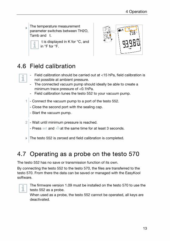
The temperature measurement parameter switches between TH2O, Tamb and t.
t is displayed in K for °C, and in °F for °F.
4.6 Field calibration
- Field calibration should be carried out at <15 hPa, field calibration is not possible at ambient pressure.
- The connected vacuum pump should ideally be able to create a minimum trace pressure of <0.1hPa.
- Field calibration tunes the testo 552 to your vacuum pump.
1 - Connect the vacuum pump to a port of the testo 552.
- Close the second port with the sealing cap.
- Start the vacuum pump.
2 - Wait until minimum pressure is reached.
- Press and at the same time for at least 3 seconds.
The testo 552 is zeroed and field calibration is completed.
4.7 Operating as a probe on the testo 570 The testo 552 has no save or transmission function of its own.
By connecting the testo 552 to the testo 570, the files are transferred to the testo 570. From there the data can be saved or managed with the EasyKool software.
The firmware version 1.09 must be installed on the testo 570 to use the testo 552 as a probe. When used as a probe, the testo 552 cannot be operated, all keys are deactivated.
4 Operation
14
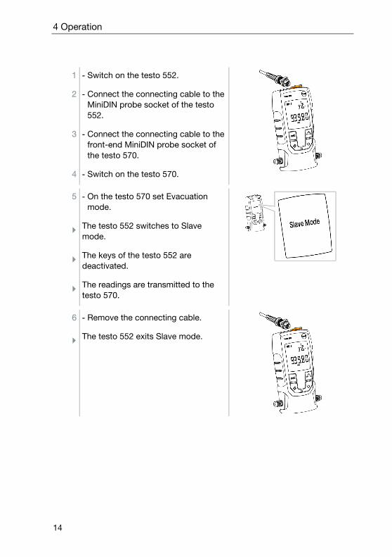
1 - Switch on the testo 552.
2 - Connect the connecting cable to the MiniDIN probe socket of the testo 552.
3 - Connect the connecting cable to the front-end MiniDIN probe socket of the testo 570.
4 - Switch on the testo 570.
5 - On the testo 570 set Evacuation mode.
The testo 552 switches to Slave mode.
The keys of the testo 552 are deactivated.
The readings are transmitted to the testo 570.
6 - Remove the connecting cable.
The testo 552 exits Slave mode.

5 Maintenance
15
5 Maintenance
5.1 Changing batteries 1 - Switch the instrument off.
2 - Flip hook up.
3 - Open the battery compartment.
4 - Remove batteries.
5 - Insert new batteries, observing the indications inside the battery compartment.
6 - Close the battery compartment.
7 - Fold hook down.
5.2 Cleaning the instrument ATTENTION
Aggressive cleaning agents or solvents. Sensor may be damaged!
- The sensor should not be cleaned.
ATTENTION Aggressive cleaning agents or solvents. The instrument may be damaged!
- Only clean the instrument housing.
- Use mild household cleaning agents or soapy water.
- Close the connections using the sealing caps.
- Close the battery compartment lid.

6 Tips and assistance
16
1 - Wipe the instrument housing with a damp cloth. Use mild household cleaning agents or soapy water for this.
6 Tips and assistance
6.1 Questions and answers Question Possible cause / solution
Readings are incorrect. - Check that the testo 552 is connected properly.
- Connect the testo 552 directly to the vacuum pump in order to check the values.
- Check that all hoses are leak-tight. - Carry out the field calibration of testo 552.
If we have not been able to answer your question, please contact your dealer or Testo Customer Service. You will find contact details on the back of this document or on the website www.testo.com/service-contact
6.2 Accessories and spare parts Description Item no.
Connecting cable for testo 552 0554 5520


0970 5520 en 01