Embed Size (px)
Citation preview
TESTO ITC KORINNA 28mm Allargato
MONOBLOCK DIRECTIONALCONTROL VALVE
SD5
2 DAU003A
Simple , compact and heavy duty designed monoblock valves from 1 to 7 sections for open and closed centre hydraulic systems..
H Fitted with a main pressure relief valve and a load check valve.
H Available with parallel, series or tandem circuit.
H Optional carry--over port (only for parallel or tandem circuit).
H Diameter 16 mm -- 0.63 in interchangeable spools.
H A wide variety of service port valve options.
H Actuation is manual, pneumatic, electro--pneumatic, hydraulic, electro--hydraulic, with solenoid and remote with flexible cables
spool control kits.
Features
WARNING!
All specifications of this catalogue refer to the standard product at this date.
Walvoil, oriented to a continuous improvement, reserves the right to
discontinue, modify or revise the specifications, without notice.
WALVOIL IS NOT RESPONSIBLE FOR ANY DAMAGE CAUSED BY AN
INCORRECT USE OF THE PRODUCT.1st edition April 2005:
This edition supercedes all prior documents.
Additional information
This catalogue shows the product in the most standard configurations.
Please contact Sales Dpt. for more detailed information or special request.
SD5
3DAU003A
Contents
Working condition 4. . . . . . . . . . . . . . . . . . . . . . . . . . . . . . . . .
Performance data 5. . . . . . . . . . . . . . . . . . . . . . . . . . . . . . . . . .
Directional valve with left inlet 7. . . . . . . . . . . . . . . . . . . . . .
Directional valve with right inlet 77. . . . . . . . . . . . . . . . . . . .
Installation and maintenance 126. . . . . . . . . . . . . . . . . . . . .
Accessories 129. . . . . . . . . . . . . . . . . . . . . . . . . . . . . . . . . . . . .
1.Working conditions
Standard threads
SD5
4 DAU003A
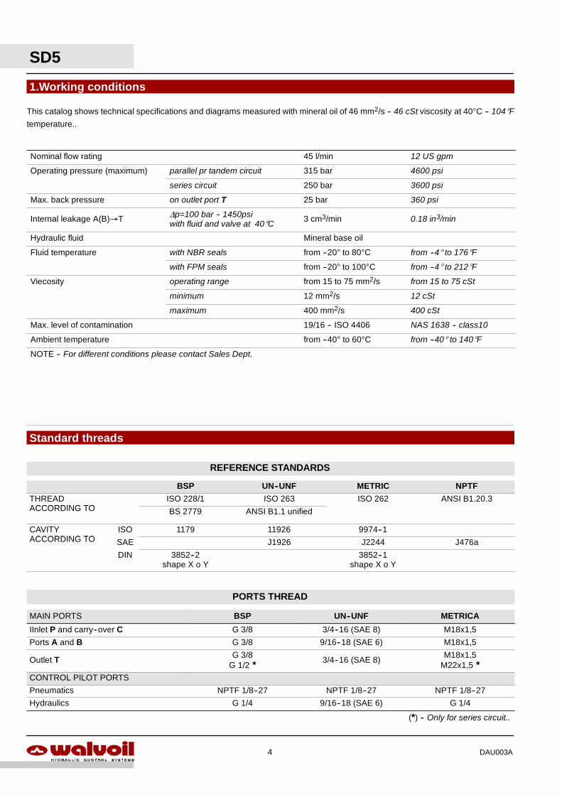
This catalog shows technical specifications and diagrams measured with mineral oil of 46 mm2/s -- 46 cSt viscosity at 40°C -- 104°F
temperature..
Nominal flow rating 45 l/min 12 US gpm
Operating pressure (maximum) parallel pr tandem circuit 315 bar 4600 psi
series circuit 250 bar 3600 psi
Max. back pressure on outlet port T 25 bar 360 psi
Internal leakage A(B)→T ∆p=100 bar -- 1450psiwith fluid and valve at 40°C 3 cm3/min 0.18 in3/min
Hydraulic fluid Mineral base oil
Fluid temperature with NBR seals from --20° to 80°C from --4° to 176°F
with FPM seals from --20° to 100°C from --4° to 212°F
Viecosity operating range from 15 to 75 mm2/s from 15 to 75 cSt
minimum 12 mm2/s 12 cSt
maximum 400 mm2/s 400 cSt
Max. level of contamination 19/16 -- ISO 4406 NAS 1638 -- class10
Ambient temperature from --40° to 60°C from --40° to 140°F
NOTE -- For different conditions please contact Sales Dept.
REFERENCE STANDARDS
BSP UN--UNF METRIC NPTF
THREADACCORDING TO
ISO 228/1 ISO 263 ISO 262 ANSI B1.20.3ACCORDING TO BS 2779 ANSI B1.1 unified
CAVITYACCORDING TO
ISO 1179 11926 9974--1ACCORDING TO SAE J1926 J2244 J476a
DIN 3852--2shape X o Y
3852--1shape X o Y
PORTS THREAD
MAIN PORTS BSP UN--UNF METRICA
IInlet P and carry--over C G 3/8 3/4--16 (SAE 8) M18x1,5
Ports A and B G 3/8 9/16--18 (SAE 6) M18x1,5
Outlet T G 3/8G 1/2 * 3/4--16 (SAE 8) M18x1,5
M22x1,5 *CONTROL PILOT PORTS
Pneumatics NPTF 1/8--27 NPTF 1/8--27 NPTF 1/8--27
Hydraulics G 1/4 9/16--18 (SAE 6) G 1/4
(*) -- Only for series circuit..
0
10
20
30
40
0 15 30 45 60
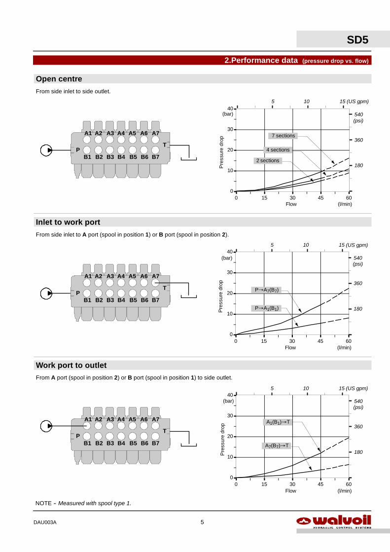
A1(B1)→T
Flow
Pre
ssur
edr
op
540
360
180
(l/min)
(bar)(psi)
A7(B7)→T
5 10 15 (US gpm)
0
10
20
30
40
0 15 30 45 60Flow
Pre
ssur
edr
op
540
360
180
(l/min)
(bar)(psi)
P→A7(B7)
P→A1(B1)
5 10 15 (US gpm)
0
10
20
30
40
0 15 30 45 60Flow
Pre
ssur
edr
op
540
360
180
(l/min)
(bar)(psi)
2 sections
4 sections
7 sections
5 10 15 (US gpm)
2.Performance data (pressure drop vs. flow)
Work port to outlet
Inlet to work port
Open centre
A1 A2 A3
B1 B2 B3P
T
A4 A5 A6
B4 B5 B6 B7
A7
From side inlet to side outlet.
From side inlet to A port (spool in position 1) or B port (spool in position 2).
From A port (spool in position 2) or B port (spool in position 1) to side outlet.
NOTE -- Measured with spool type 1.
A1 A2 A3
B1 B2 B3P
T
A4 A5 A6
B4 B5 B6 B7
A7
A1 A2 A3
B1 B2 B3P
T
A4 A5 A6
B4 B5 B6 B7
A7
SD5
5DAU003A

SD5
6 DAU003A
SD5
7DAU003A
3.Contents
Directional valve with parallel circuitDimensional data 8. . . . . . . . . . . . . . . . . . . . . . . . . . . . . . . . . . .
Hydraulic circuit 9. . . . . . . . . . . . . . . . . . . . . . . . . . . . . . . . . . . .
Ordering codes 10. . . . . . . . . . . . . . . . . . . . . . . . . . . . . . . . . . . .
Inlet relief options 12. . . . . . . . . . . . . . . . . . . . . . . . . . . . . . . . . .
Spools 13. . . . . . . . . . . . . . . . . . . . . . . . . . . . . . . . . . . . . . . . . . .
“A” side spool positioners 20. . . . . . . . . . . . . . . . . . . . . . . . . .
“B” side options 39. . . . . . . . . . . . . . . . . . . . . . . . . . . . . . . . . . .
Complete controls 44. . . . . . . . . . . . . . . . . . . . . . . . . . . . . . . . .
Outlet port options 49. . . . . . . . . . . . . . . . . . . . . . . . . . . . . . . . .
Service and auxiliary valves
ordering codes 52. . . . . . . . . . . . . . . . . . . . . . . . . . . . . . . . .
port relief valves 54. . . . . . . . . . . . . . . . . . . . . . . . . . . . . . . .
pilot check valves 56. . . . . . . . . . . . . . . . . . . . . . . . . . . . . .
flange mounted relief valves 55. . . . . . . . . . . . . . . . . . . . .
antishock valves 57. . . . . . . . . . . . . . . . . . . . . . . . . . . . . . .
fixed setting antishock and anticavitation valves 59. . . . .
adjustable setting antishock and anticavitation valves 61
flow control valves 65. . . . . . . . . . . . . . . . . . . . . . . . . . . . . .
Other executionsMain features 69. . . . . . . . . . . . . . . . . . . . . . . . . . . . . . . . . . . . .
Directional valve SD5/1--N 70. . . . . . . . . . . . . . . . . . . . . . . . . .
Directional valve SD5/1--D 71. . . . . . . . . . . . . . . . . . . . . . . . . .
Directional valve SD5--S with series circuit 72. . . . . . . . . . . .
Directional valve SD5--SP with tandem circuit 74. . . . . . . . . .
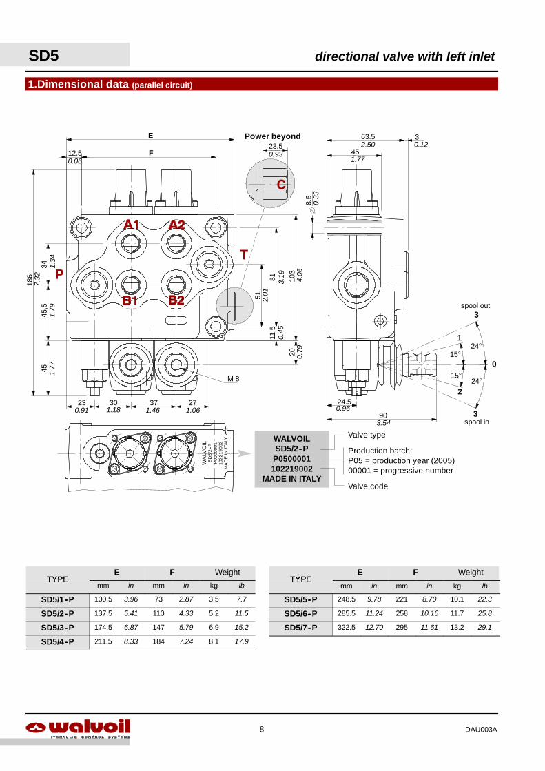
1.Dimensional data (parallel circuit)
WALVOILSD5/2--P
P0500001102219002
MADE IN ITALY
30 37
51
81
34
186 103
45
12.5
11.5
23
45,5
27
M 8
20
90
24.5
45
63.5 3
8.5
23.5Power beyond
F
E
WA
LVO
ILS
D5/
2--P
P00
0000
110
2219
002
MA
DE
INIT
ALY
Valve code
Production batch:P05 = production year (2005)00001 = progressive number
Valve type
0.06
7.32
1.34
1.79
1.77
0.91 1.18 1.46 1.06
0.79
0.45
2.01
3.19 4.06
0.93
0.33
2.50 0.12
1.77
3.54
0.96
15°
15°
1
2
0
24°
24°
spool out3
3spool in
SD5 directional valve with left inlet
8 DAU003A
TYPEE F Weight
TYPEE F Weight
TYPEmm in mm in kg lb
TYPEmm in mm in kg lb
SD5/1--P 100.5 3.96 73 2.87 3.5 7.7 SD5/5--P 248.5 9.78 221 8.70 10.1 22.3
SD5/2--P 137.5 5.41 110 4.33 5.2 11.5 SD5/6--P 285.5 11.24 258 10.16 11.7 25.8
SD5/3--P 174.5 6.87 147 5.79 6.9 15.2 SD5/7--P 322.5 12.70 295 11.61 13.2 29.1
SD5/4--P 211.5 8.33 184 7.24 8.1 17.9
A
B
T
P
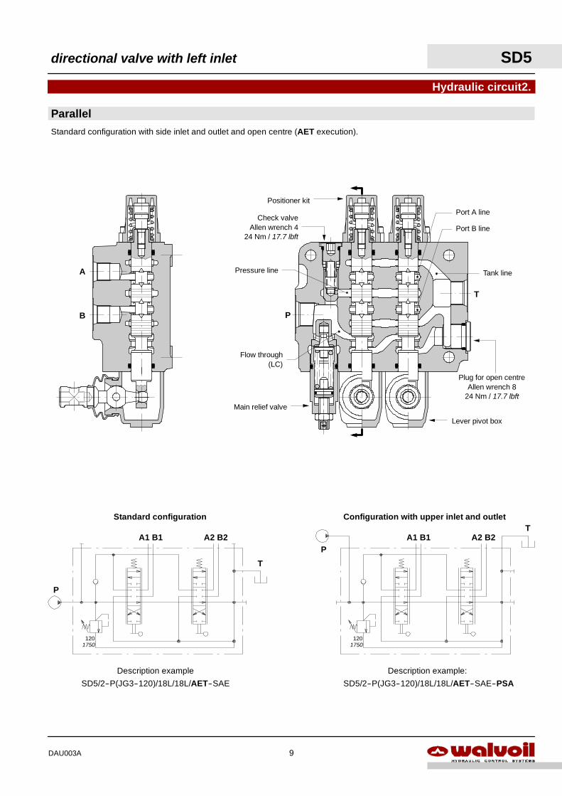
Parallel
Hydraulic circuit2.
Standard configuration with side inlet and outlet and open centre (AET execution).
Main relief valve
Lever pivot box
Check valveAllen wrench 4
24 Nm / 17.7 lbft
Configuration with upper inlet and outlet
PA1 B1 A2 B2
T
Description example:
SD5/2--P(JG3--120)/18L/18L/AET--SAE--PSA
P
A1 B1 A2 B2
T
Description example
SD5/2--P(JG3--120)/18L/18L/AET--SAE
Standard configuration
Tank line
Flow through(LC)
Pressure line
Port A line
Port B line
Positioner kit
Plug for open centreAllen wrench 8
24 Nm / 17.7 lbft
1201750
1201750
directional valve with left inlet SD5
9DAU003A
SD5 directional valve with left inlet
10 DAU003A
2. Inlet relief options page 12
1. Body kits *
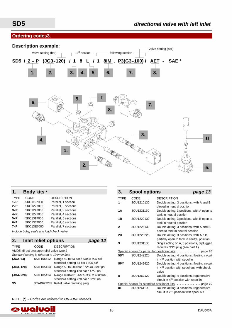
Ordering codes3.
2.
2.
SD5 / 2 -- P (JG3--120) / 1 8 L / 1 8IM . P3(G3--100) / AET -- SAE *
TYPE CODE DESCRIPTION1--P 5KC1197000 Parallel, 1 section2--P 5KC1227000 Parallel, 2 sections3--P 5KC1247000 Parallel, 3 sections4--P 5KC1277000 Parallel, 4 sections5--P 5KC1317000 Parallel, 5 sections6--P 5KC1357000 Parallel, 6 sections7--P 5KC13E7000 Parallel, 7 sections
TYPE CODE DESCRIPTIONVMD5 direct pressure relief valve type JStandard setting is referred to 10 l/min flow.(JG2--63) 5KIT105412 Range 40 to 63 bar / 580 to 900 psi
standard setting 63 bar / 900 psi(JG3--120) 5KIT105413 Range 50 to 200 bar / 725 to 2900 psi
standard setting 120 bar / 1750 psi(JG4--220) 5KIT105414 Range 160 to 315 bar / 2300 to 4600 psi
standard setting 220 bar / 3200 psiSV XTAP623282 Relief valve blanking plug
4. 5.
Include boby, seals and load check valve.
1st section following section
1.
Description example:
II
5.
4.
I
8.
9.
1. 3.
3. Spool options page 13TYPE CODE DESCRIPTION1 3CU1210130 Double acting, 3 positions, with A and B
closed in neutral position1A 3CU1221130 Double acting, 3 positions, with A open to
tank in neutral position1B 3CU1222130 Double acting, 3 positions, with B open to
tank in neutral position2 3CU1225130 Double acting, 3 positions, with A and B
open to tank in neutral position2H 3CU1225225 Double acting, 3 positions, with A e B
partially open to tank in neutral position3 3CU1231130 Single acting on A, 3 positions, B plugged
requires G3/8 plug (see part I )Special spools for particular positioner kits page 16. . . . . . . . . . . . . . .5DY 3CU1242220 Double acting, 4 positions, floating circuit
in 4th position with spool in5PY 3CU1245620 Double acting, 4 positions, floating circuit
in 4th position with spool out, with checkvalve
8 3CU1262120 Double acting, 4 positions, regenerativecircuit in 4th position with spool in
Special spools for standard positioner kits page 19. . . . . . . . . . . . . . . .8F 3CU1261100 Double acting, 3 positions, regenerative
circuit in 2nd position with spool out
NOTE (*) -- Codes are referred to UN- UNF threads.
7.
7.
3.
6. 8.
6.
Valve setting (bar)Valve setting (bar)
directional valve with left inlet SD5
11DAU003A
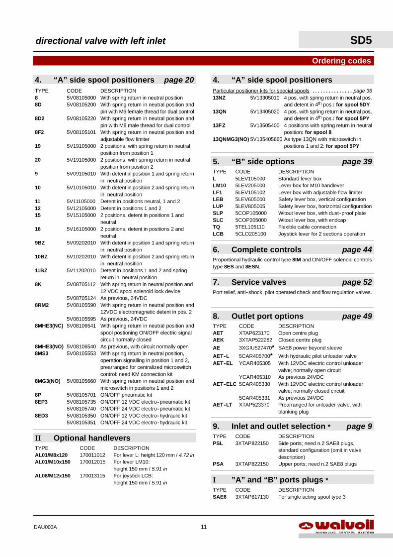
7. Service valves page 52
I ”A” and “B” ports plugs *
8. Outlet port options page 49TYPE CODE DESCRIPTIONAET XTAP623170 Open centre plugAEK 3XTAP522282 Closed centre plug
AE 3XGIU527470* SAE8 power beyond sleeve
AET--L 5CAR405700* With hydraulic pilot unloader valveAET--EL YCAR405305 With 12VDC electric control unloader
valve; normally open circuitYCAR405310 As previous 24VDC
AET--ELC 5CAR405330 With 12VDC electric control unloadervalve; normally closed circuit
5CAR405331 As previous 24VDCAET--LT XTAP523370 Prearranged for unloader valve, with
blanking plug
II Optional handlevers9. Inlet and outlet selection * page 9
4. “A” side spool positioners page 20
Ordering codes
TYPE CODE DESCRIPTION8 5V08105000 With spring return in neutral position8D 5V08105200 With spring return in neutral position and
pin with M6 female thread for dual control8D2 5V08105220 With spring return in neutral position and
pin with M8 male thread for dual control8F2 5V08105101 With spring return in neutral position and
adjustable flow limiter19 5V19105000 2 positions, with spring return in neutral
position from position 120 5V19105000 2 positions, with spring return in neutral
position from position 29 5V09105010 With detent in position 1 and spring return
in neutral position10 5V10105010 With detent in position 2 and spring return
in neutral position11 5V11105000 Detent in positions neutral, 1 and 212 5V12105000 Detent in positions 1 and 215 5V15105000 2 positions, detent in positions 1 and
neutral16 5V16105000 2 positions, detent in positions 2 and
neutral9BZ 5V09202010 With detent in position 1 and spring return
in neutral position10BZ 5V10202010 With detent in position 2 and spring return
in neutral position11BZ 5V11202010 Detent in positions 1 and 2 and spring
return in neutral position8K 5V08705112 With spring return in neutral position and
12 VDC spool solenoid lock device5V08705124 As previous, 24VDC
8RM2 5V08105590 With spring return in neutral position and12VDC electromagnetic detent in pos. 2
5V08105595 As previous, 24VDC8MHE3(NC) 5V08106541 With spring return in neutral position and
spool postioning ON/OFF electric signalcircuit normally closed
8MHE3(NO) 5V08106540 As previous, with circuit normally open8MS3 5V08105553 With spring return in neutral position,
operation signalling in position 1 and 2,prearranged for centralized microswitchcontrol: need KM connection kit
8MG3(NO) 5V08105660 With spring return in neutral position andmicroswitch in positions 1 and 2
8P 5V08105701 ON/OFF pneumatic kit8EP3 5V08105735 ON/OFF 12 VDC electro--pneumatic kit
5V08105740 ON/OFF 24 VDC electro--pneumatic kit8ED3 5V08105350 ON/OFF 12 VDC electro--hydraulic kit
5V08105351 ON/OFF 24 VDC electro--hydraulic kit
TYPE CODE DESCRIPTIONPSL 3XTAP822150 Side ports; need n.2 SAE8 plugs,
standard configuration (omit in valvedescription)
PSA 3XTAP822150 Upper ports; need n.2 SAE8 plugs
TYPE CODE DESCRIPTIONAL01/M8x120 170011012 For lever L: height 120 mm / 4.72 inAL01/M10x150 170012015 For lever LM10:
height 150 mm / 5.91 inAL08/M12x150 170013115 For joystick LCB:
height 150 mm / 5.91 inTYPE CODE DESCRIPTIONSAE6 3XTAP817130 For single acting spool type 3
Port relief, anti--shock, pilot operated check and flow regulation valves.
6. Complete controls page 44Proportional hydraulic control type 8IM and ON/OFF solenoid controlstype 8ES and 8ESN.
5. “B” side options page 39TYPE CODE DESCRIPTIONL 5LEV105000 Standard lever boxLM10 5LEV205000 Lever box for M10 handleverLF1 5LEV105102 Lever box with adjustable flow limiterLEB 5LEV605000 Safety lever box, vertical configurationLUP 5LEV805005 Safety lever box, horizontal configurationSLP 5COP105000 Witout lever box, with dust--proof plateSLC 5COP205000 Witout lever box, with endcapTQ 5TEL105110 Flexible cable connectionLCB 5CLO205100 Joystick lever for 2 sections operation
4. “A” side spool positionersParticular positioner kits for special spools page 36. . . . . . . . . . . . . . .13NZ 5V13305010 4 pos. with spring return in neutral pos.
and detent in 4th pos.: for spool 5DY13QN 5V13405020 4 pos. with spring return in neutral pos.
and detent in 4th pos.: for spool 5PY13FZ 5V13505400 4 positions with spring return in neutral
position: for spool 813QNMG3(NO) 5V135405660 As type 13QN with microswitch in
positions 1 and 2: for spool 5PY
0
100
200
300
400
0 20 40 600
100
200
300
400
0 20 40 600
100
200
300
400
0 20 40 60
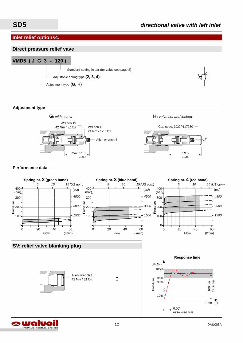
Spring nr. 4 (red band)Spring nr. 3 (blue band)Spring nr. 2 (green band)
Flow
Pre
ssur
e
(l/min)
(bar)
Flow
Pre
ssur
e
(l/min)
(bar)
Flow
Pre
ssur
e
(l/min)
(bar)
0,05”RESPONSE TIME
10%
100
bar90%
95%
105%
Pre
ssur
e
Time (”)
(% ∆P)
Response time
(psi)
4500
3000
1500
(psi)
4500
3000
1500
(psi)
4500
3000
150014
50ps
i
5 10 15 (US gpm)5 10 15 (US gpm) 5 10 15 (US gpm)
Direct pressure relief vave
Inlet relief options4.
VMD5 ( J G 3 -- 120 )
Standard setting in bar (for value see page 8)
Performance data
Adjustment type
Adjustment type (G, H)
Adjustable spring type (2, 3, 4).
G: with screw H: valve set and locked
59.5max. 51.5
SV: relief valve blanking plug
Wrench 1942 Nm / 31 lbft Wrench 13
24 Nm / 17.7 lbft
Allen wrench 4
Allen wrench 1042 Nm / 31 lbft
Cap code: 3COP117260
2.03 2.34
SD5 directional valve with left inlet
12 DAU003A

F
J
YP(on ports) = 63bar / 900 psiP(on ports) = 100bar / 1450 psiP(on ports) = 250bar / 3600 psi
Qin = 45 l/min -- 12 US gpm
0
20
40
60
0.0 1.0 2.0 3.0 4.0 5.0
Flo
w
Stroke
Spool metering P→A(B)
(mm)
(l/min )
5.5
(in)0.1 0.2
5
10
15(US gpm)
0
20
40
60
0.0 1.0 2.0 3.0 4.0 5.0
Flo
w
Stroke (mm)
(l/min )
Spool metering A(B)→T
5.5
(in)0.1 0.2
5
10
15(US gpm)
Type 1
5.Spool options
201
201
201A B
P T
P--A--B--T closed, with flow through line (LC) open
A
"
P → A B → T
P→ B A → T
Performance data
A B
P T
A B
P T
FJ
YF J
Y
A B
T P LCT
A B
T P LCT
A B
T P LCT
142
20
29100.39
0.35
0.79
5.59
For special requirement, spool 1CS code 3CU1210200 suggested for flow from 15 to 30 l/min and spool 1CEX code 3CU1210230
suggested for flow up to 15 l/min -- 4 US gpm , are available.
stroke:+ 5.5 mm / 0.22 in
stroke:+ 5.5 mm / 0.22 in
directional valve with left inlet SD5
13DAU003A
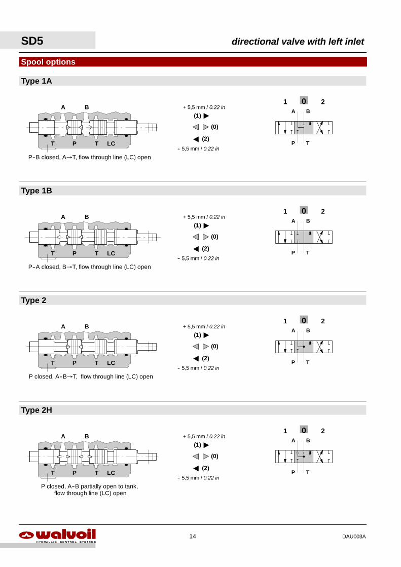
Type 2
Type 1B
Type 1A
Spool options
201A B
P T
Type 2H
201A B
P T
201A B
P T
201A B
P T
A B
T P LCT
A B
T P LCT
A B
T P LCT
A B
T P LCT
P--B closed, A→T, flow through line (LC) open
P--A closed, B→T, flow through line (LC) open
P closed, A--B→T, flow through line (LC) open
P closed, A--B partially open to tank,flow through line (LC) open
A
-- 5,5 mm / 0.22 in
"
+ 5,5 mm / 0.22 in
(0)
(1)
(2)
A
-- 5,5 mm / 0.22 in
"
+ 5,5 mm / 0.22 in
(0)
(1)
(2)
A
-- 5,5 mm / 0.22 in
"
+ 5,5 mm / 0.22 in
(0)
(1)
(2)
A
-- 5,5 mm / 0.22 in
"
+ 5,5 mm / 0.22 in
(0)
(1)
(2)
SD5 directional valve with left inlet
14 DAU003A
A
T P LCT
A
T P LCT
A
T P LCT
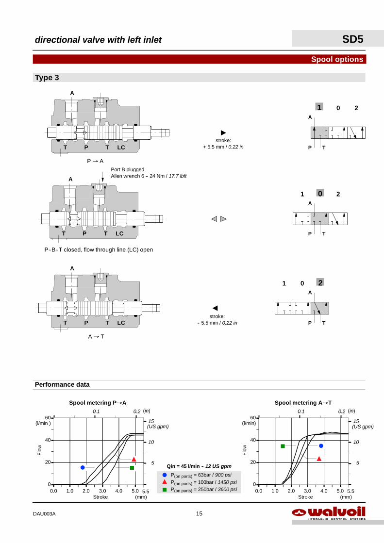
F
J
YP(on ports) = 63bar / 900 psiP(on ports) = 100bar / 1450 psiP(on ports) = 250bar / 3600 psi
Qin = 45 l/min -- 12 US gpm
0
20
40
60
0.0 1.0 2.0 3.0 4.0 5.0
Flo
w
Stroke (mm)
(l/min)
Spool metering A→T
5.5
(in)0.1 0.2
5
10
15(US gpm)
0
20
40
60
0.0 1.0 2.0 3.0 4.0 5.0
Flo
w
Stroke
Spool metering P→A
(mm)
(l/min )
5.5
(in)0.1 0.2
5
10
15(US gpm)
A
"
A
P T
A
P T
201A
P T
Type 3
Spool options
201
201
P--B--T closed, flow through line (LC) open
P → A
A → T
Performance data
FJ
Y
F J
Y
Port B pluggedAllen wrench 6 -- 24 Nm / 17.7 lbft
stroke:+ 5.5 mm / 0.22 in
stroke:-- 5.5 mm / 0.22 in
directional valve with left inlet SD5
15DAU003A
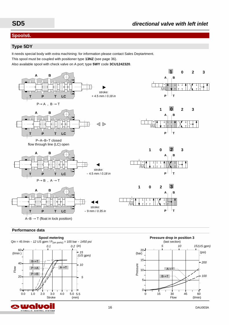
0
5
10
15
20
0 15 30 45 60
Pre
ssur
e
Flow (l/min)
(bar)
Pressure drop in position 3(last section)
B→T
A→T
(psi)
200
100
0
20
40
60
0.0 1.0 2.0 3.0 4.0 5.0
Spool meteringQin = 45 l/min -- 12 US gpm / P(on ports) = 100 bar -- 1450 psi
Flo
w
Stroke (mm)
(l/min )
5.5
Performance data
(in)0.1 0.2
P→A A→T
P→B
B→T
AA
A
"
A B
T P LCT
A B
T P LCT
A B
T P LCT
Spools6.
Type 5DY
P→ B , A → T
A--B → T (float in lock position)
201
201
201
201 3
3
3
3A B
P T
A B
P T
A B
P T
A B
P T
P→ A , B → T
It needs special body with extra machining: for information please contact Sales Deptartment.
This spool must be coupled with positioner type 13NZ (see page 36).
Also available spool with check valve on A port; type 5WY code 3CU1242320.
P--A--B--T closedflow through line (LC) open
A B
T P LCTstroke:
+ 4.5 mm / 0.18 in
stroke:-- 4.5 mm / 0.18 in
stroke:-- 9 mm / 0.35 in
5
10
15(US gpm)
5 10 15(US gpm)
SD5 directional valve with left inlet
16 DAU003A

0
20
40
60
0.0 1.0 2.0 3.0 4.0 5.0
A
A B
T P LCT
It needs special body with extra machining: for information please contact Sales Department.
This spool must be coupled with positioner type 13QN (see page 36) and 13QNMG3 (see page 37).
7.Spools options
Type 5PY
P→ B , A → T
013 2A B
P T
013 2A B
P T
013 2A B
P T
013 2A B
P T
P→ A , B → T
P--A--B--T closed,with flow through line (LC) open
A B
T P LCT
A B
T P LCT
A B
T P LCT
0
5
10
15
20
0 15 30 45 60
Pre
ssio
ne
Portata (l/min)
(bar)
Pressure drop in position 3(last section)
A(B)→T
Spool meteringQin = 45 l/min -- 12 US gpm / P(on ports) = 100 bar -- 1450 psi
Flo
w
Stroke (mm)
(l/min)
5.5
Performance data
(in)0.1 0.2
(psi)
200
100
""
"
P→A(B)B→T
A→T
stroke:-- 4.5 mm / 0.18 in
stroke:+ 4.5 mm / 0.18 in
stroke:+ 9 mm / 0.35 in
5 10 15(US gpm)
5
10
15(US gpm)
directional valve with left inlet SD5
17DAU003A
Pressure drop in positione 3(last section)
0
5
10
15
20
0 15 30 45 60
Pre
ssur
e
Flow (l/min)
(bar)
P→B
A→B
(psi)
200
100
5 10 15(US gpm)
Stroke
0
20
40
60
0.0 1.0 2.0 3.0 4.0 5.0
Flo
w
(mm)
(l/min )
5.5(mm)
(in)0.1 0.2
P→A(B)A(B)→T
Spool meteringQin = 45 l/min -- 12 US gpm / P(on ports) = 100 bar -- 1450 psi
5
10
15(US gpm)
AA
A
"
A B
T P LCT
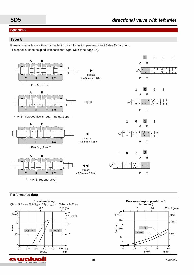
It needs special body with extra machining: for information please contact Sales Department.
This spool must be coupled with positioner type 13FZ (see page 37).
P→ B , A → T
P → A--B (regenerative)
201
201
201 3
3
3A B
P T
A B
P T
A B
P T
P→ A , B → T
Type 8
Spools8.
201 3A B
P T
P--A--B--T closed flow through line (LC) open
A B
T P LCT
A B
T P LCT
A B
T P LCT
Performance data
stroke:-- 7.5 mm / 0.30 in
stroke:-- 4.5 mm / 0.18 in
stroke:+ 4.5 mm / 0.18 in
SD5 directional valve with left inlet
18 DAU003A

0
5
10
15
20
0 15 30 45 60
Pre
ssur
e
Flow (l/min)
(bar)
Pressure drop in position 1(last section)
P→A
B→A
(psi)
200
100
5 10 15(US gpm)
0
20
40
60
0.0 1.0 2.0 3.0 4.0 5.0
Flo
w
Stroke (mm)
(l/min)
5.5
P→BA→T
(in)0.1 0.2
Spool meteringQin = 45 l/min -- 12 US gpm / P(on ports) = 100 bar -- 1450 psi
5
10
15(US gpm)
201A B
P T
Type 8F
9.Spool options
201
201A B
P T
A
"
Performance data
A B
P T
P--A--B--T closed flow through line (LC) open
P→ B , A → T
It needs special body with extra machining: for information please contact Sales Department.
P → A--B (regenerative)
A B
T P LCT
A B
T P LCT
A B
T P LCT
stroke:+ 5.5 mm / 0.22 in
stroke:-- 5.5 mm / 0.22 in
directional valve with left inlet SD5
19DAU003A
Allen wrench 46.6 Nm / 4.9 lbft
36.5
84
401.57 1.44
3.31
36.51.44
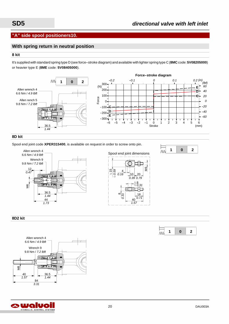
--300
--200
--100
0
100
200
300
--6 --5 --4 --3 --2 --1 0 1 2 3 4 5 6Stroke
For
ce
(mm)
(N)
Force--stroke diagram
D
DE
C
C
E
0.1 0.2 (in)
40
20
(lbf)--0.1--0.2 0
60
0
--40
--20
--60
With spring return in neutral position
”A” side spool positioners10.
8 kit
8D kit
8D2 kit
201
201
M8
201
It’s supplied with standard spring type D (see force--stroke diagram) and available with lighter spring type C (8MC code:5V08205000)
or heavier type E (8ME code: 5V08405000).
Allen rench 59.8 Nm / 7.2 lbft
Wrench 99.8 Nm / 7.2 lbft
M6
36.5
44
12
1.73
1.44
0.47
Allen wrench 46.6 Nm / 4.9 lbft
Wrench 99.8 Nm / 7.2 lbft
Allen wrench 46.6 Nm / 4.9 lbft
Spool end joint code XPER315400, is available on request in order to screw onto pin.
10
40
18
204 M
6
15
8
8
Spool end joint dimensions
0.160.39 0.79
0.31
0.71
1.57
0.31
0.59
SD5 directional valve with left inlet
20 DAU003A

201
36.51.44
With spring return in neutral position
“A” side spool positioners
8F2 kit
19 kit
M8x
1
20
20 kit
--300
--200
--100
0
100
200
300
0 1 2 3 4 5 6Stroke
For
ce
(mm)
(N)
Force--stroke diagram
--300
--200
--100
0
100
200
300
--6 --5 --4 --3 --2 --1 0Stroke
For
ce
(mm)
(N)
Force--stroke diagram
51.52.03
36.51.44
Allen wrench 46.6 Nm / 4.9 lbft
(in)
40
20
60
0
--40
--20
--60
(lbf)0.1 0.2
(in)
40
20
60
0
--40
--20
--60
(lbf)--0.1--0.2
01
Allen wrench 59.8 Nm / 7.2 lbft
Allen wrench 4
Wrench 1324 Nm / 17.7 lbft
Allen wrench 46.6 Nm / 4.9 lbft
Allen wrench 59.8 Nm / 7.2 lbft
36.5
Allen wrench 59.8 Nm / 7.2 lbft
Allen wrench 46.6 Nm / 4.9 lbft
1.44
directional valve with left inlet SD5
21DAU003A

Operating featuresLocking and release force : 100 N / 22.5 lbf ±10%. . . . . . . .
36.51.44
Allen wrench 59.8 Nm / 7.2 lbft
Allen wrench 46.6 Nm / 4.9 lbft
Operating featuresLocking and release force : 100 N / 22.5 lbf ±10%. . . . . . . .
36.51.44
Allen wrench 59.8 Nm / 7.2 lbft
Allen wrench 46.6 Nm / 4.9 lbft
Operating featuresLocking and release force : 100 N / 22.5 lbf ±10%. . . . . . . .
36.5
Allen wrench 46.6 Nm / 4.9 lbft
1.4436,5
Allen wrench 59.8 Nm / 7.2 lbft
Operating featuresLocking and release force : 120 N / 27 lbf ±10%. . . . . . . .
36.51.44
Allen wrench 59.8 Nm / 7.2 lbft
Allen wrench 46.6 Nm / 4.9 lbft
Operating featuresLocking force (from pos. 0 to 2) : 150 N / 33.7 lbf ±10%. . .Release force (from pos. 2 to 0) : 140 N / 31.5 lbf ±10%. . .
41
Allen wrench 46.6 Nm / 4.9 lbft
1.61
Allen wrench 59.8 Nm / 7.2 lbft
Operating featuresLocking force (from pos. 0 to 1) : 150 N / 33.7 lbf ±10%. . .Release force (from pos. 1 to 0) : 140 N / 31.5 lbf ±10%. . .
45,545.5
Allen wrench 59.8 Nm / 7.2 lbft
Allen wrench 46.6 Nm / 4.9 lbft
1.79
201201
201
With detent
”A” side spool positioners
9 kit
11 kit
15 kit
10 kit
201
12 kit
01 20
16 kit
SD5 directional valve with left inlet
22 DAU003A

72.5
Allen wrench 46.6 Nm / 4.9 lbft
Allen wrench 59.8 Nm / 7.2 lbft
2.85
72.5
Allen wrench 46.6 Nm / 4.9 lbft
Allen wrench 59.8 Nm / 7.2 lbft
2.85
72.5
Allen wrench 46.6 Nm / 4.9 lbft
Allen wrench 59.8 Nm / 7.2 lbft
2.85
With detent and sprimg return to neutral position from either directions
11.“A” side spool positioners
9BZ kit
10BZ kit
11BZ kit
201
201
201
--300
--200
--100
0
100
200
300
--6 --5 --4 --3 --2 --1 0 1 2 3 4 5 6Stroke
For
ce
(mm)
(N)
Force--stroke diagram
Locking force: 120 N / 27 lbf ±10% / Release force: 230 N / 51.7 lbf ±10%
Detent area
2 0 1Port B Port A
3.3
0.22
--5.5
--300
--200
--100
0
100
200
300
--6 --5 --4 --3 --2 --1 0 1 2 3 4 5 6Stroke
For
ce
(mm)
(N)
Force--stroke diagram
Locking force: 120 N / 27 lbf ±10% / Release force: 230 N / 51.7 lbf ±10%
Detent area
2 0 1Port B Port A
--3.3
--5.5
5.5
--300
--200
--100
0
100
200
300
--6 --5 --4 --3 --2 --1 0 1 2 3 4 5 6Stroke
For
ce
(mm)
(N)
Force--stroke diagram
Locking force: 120 N / 27 lbf ±10% / Release force: 230 N / 51.7 lbf ±10%
2 0 1Port B Port A
--3.3
--5.5
5.5
3.3
Detent area
40
20
(lbf)60
0
--40
--20
--60
0.1 0.2 (in)--0.1--0.2 0
40
20
(lbf)60
0
--40
--20
--60
0.1 0.2 (in)--0.1--0.2 0
40
20
(lbf)60
0
--40
--20
--60
0.1 0.2 (in)--0.1--0.2 0
-0.2
2
40
20
60
0
--40
--20
--605.5
0.13
-0.1
3
-0.2
2
0.22
-0.1
9
-0.2
2
0.22
0.13
Detent area
directional valve with left inlet SD5
23DAU003A
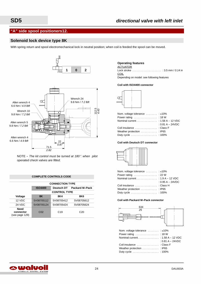
Solenoid lock device type 8K
“A” side spool positioners12.
With spring return and spool electromechanical lock in neutral position; when coil is feeded the spool can be moved.
Operating featuresACTUATORLock stroke : 3.5 mm / 0.14 in. . . . . . . . . . . . . . . . . . . . .COILDepending on model: see following features
201
NOTE -- The kit control must be turned at 180°. when pilotoperated check valves are fitted.
Coil with ISO4400 connector
Coil with Deutsch DT connector
Nom. voltage tolerance : ±10%. . . . . . . .Power rating : 18 W. . . . . . . . . . . . . . . . .Nominal current : 1.58 A -- 12 VDC. . . . . . . . . . . . . . .
: 0.81 A -- 24VDCCoil insulance : Class F. . . . . . . . . . . . . . . .Weather protection : IP65. . . . . . . . . . . .Duty cycle : 100%. . . . . . . . . . . . . . . . . . .
Nom. voltage tolerance : ±10%. . . . . . . .Power rating : 22 W. . . . . . . . . . . . . . . . .Nominal current : 1.9 A -- 12 VDC. . . . . . . . . . . . . . .
: 0.95 A -- 24VDCCoil insulance : Class H. . . . . . . . . . . . . . . .Weather protection : IP65. . . . . . . . . . . .Duty cycle : 100%. . . . . . . . . . . . . . . . . . .
Coil with Packard M--Pack connector
Nom. voltage tolerance : ±10%. . . . . . . .Power rating : 18 W. . . . . . . . . . . . . . . . .Nominal current : 1.58 A -- 12 VDC. . . . . . . . . . . . . . .
: 0.81 A -- 24VDCCoil insulance : Class F. . . . . . . . . . . . . . . .Weather protection : IP65. . . . . . . . . . . .Duty cycle : 100%. . . . . . . . . . . . . . . . . . .
634
Wrench 249.8 Nm / 7.2 lbft
Wrench 109.8 Nm / 7.2 lbft
Allen wrench 46.6 Nm / 4.9 lbft
22
71.5
112.
5
Allen wrench 46.6 Nm / 4.9 lbft
25
4.43
0.87
2.82
Allen wrench 59.8 Nm / 7.2 lbft
SD5 directional valve with left inlet
24 DAU003A
COMPLETE CONTROLS CODE
CONNECTION TYPE
ISO4400 Deutsch DT Packard M--Pack
CONTROL TYPE
Voltage 8K 8K4 8K6
12 VDC 5V08705112 5V08705412 5V08705612
24 VDC 5V08705124 5V08705424 5V08705624
Needconnector
(see page 129)C02 C19 C20
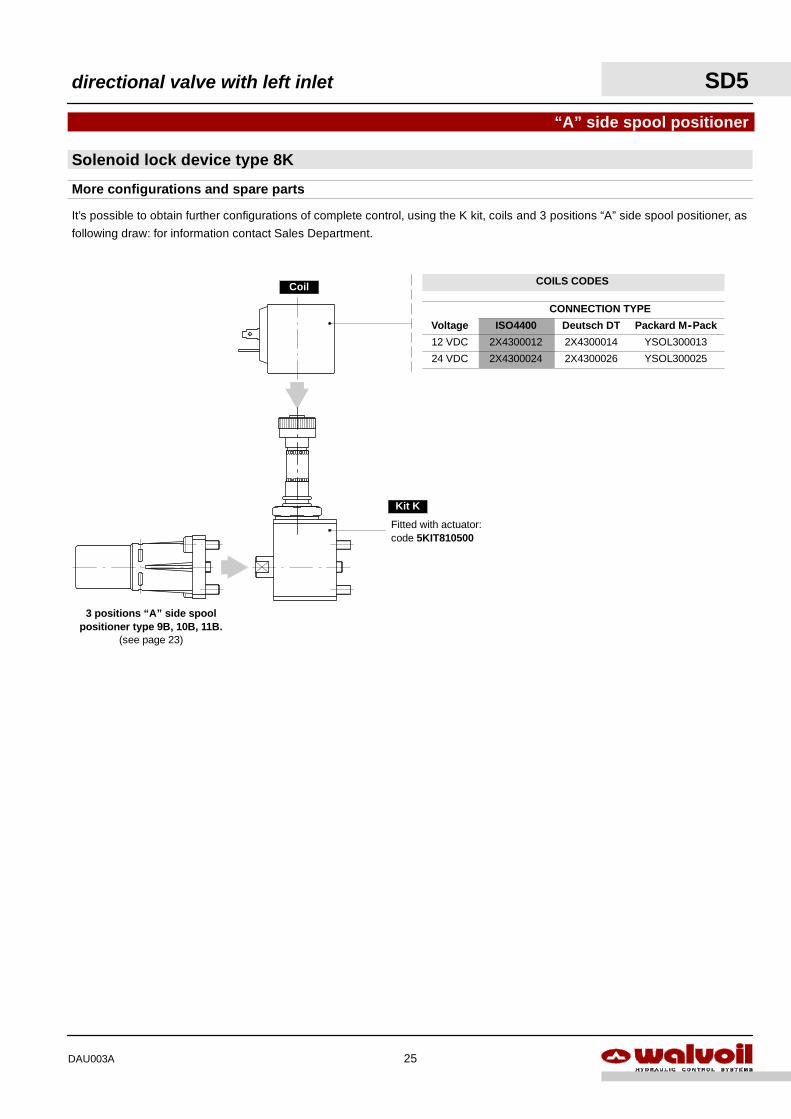
Solenoid lock device type 8K
“A” side spool positioner
It’s possible to obtain further configurations of complete control, using the K kit, coils and 3 positions “A” side spool positioner, as
following draw: for information contact Sales Department.
More configurations and spare parts
3 positions “A” side spoolpositioner type 9B, 10B, 11B.
(see page 23)
Fitted with actuator:code 5KIT810500
Coil
Kit K
directional valve with left inlet SD5
25DAU003A
COILS CODES
CONNECTION TYPE
Voltage ISO4400 Deutsch DT Packard M--Pack
12 VDC 2X4300012 2X4300014 YSOL300013
24 VDC 2X4300024 2X4300026 YSOL300025
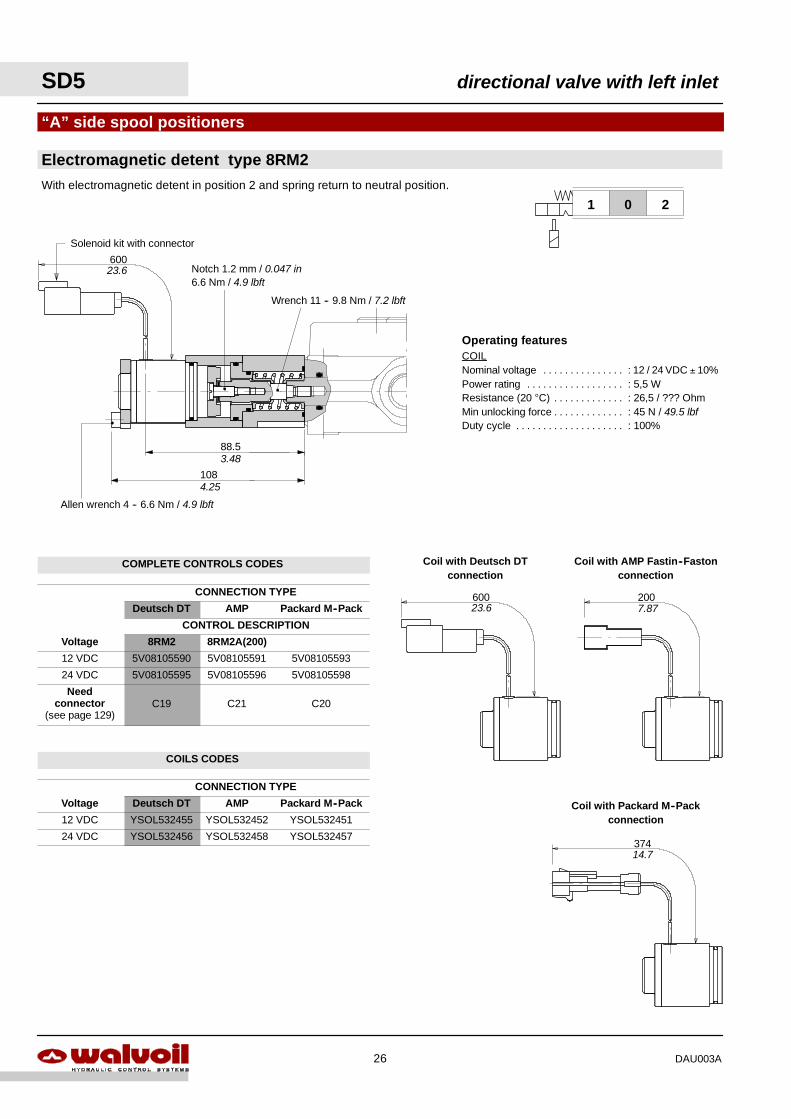
Operating featuresCOILNominal voltage : 12 / 24 VDC ± 10%. . . . . . . . . . . . . . .Power rating : 5,5 W. . . . . . . . . . . . . . . . . .Resistance (20 °C) : 26,5 / ??? Ohm. . . . . . . . . . . . .Min unlocking force : 45 N / 49.5 lbf. . . . . . . . . . . . .Duty cycle : 100%. . . . . . . . . . . . . . . . . . . .
Electromagnetic detent type 8RM2
“A” side spool positioners
108
With electromagnetic detent in position 2 and spring return to neutral position.
600
88.5
Wrench 11 -- 9.8 Nm / 7.2 lbft
Notch 1.2 mm / 0.047 in6.6 Nm / 4.9 lbft
201
600 200
374
Coil with Deutsch DTconnection
Coil with AMP Fastin--Fastonconnection
Coil with Packard M--Packconnection
4.25
3.48
23.6
Allen wrench 4 -- 6.6 Nm / 4.9 lbft
Solenoid kit with connector
7.8723.6
14.7
SD5 directional valve with left inlet
26 DAU003A
COMPLETE CONTROLS CODES
CONNECTION TYPE
Deutsch DT AMP Packard M--Pack
CONTROL DESCRIPTION
Voltage 8RM2 8RM2A(200)
12 VDC 5V08105590 5V08105591 5V08105593
24 VDC 5V08105595 5V08105596 5V08105598
Needconnector
(see page 129)C19 C21 C20
COILS CODES
CONNECTION TYPE
Voltage Deutsch DT AMP Packard M--Pack
12 VDC YSOL532455 YSOL532452 YSOL532451
24 VDC YSOL532456 YSOL532458 YSOL532457
0
12
--6 --5 --4 --3 --2 --1 0 1 2 3 4 5 6Stroke
Vol
tage
(mm)
(VDC)100%
Ouput signal with NO circuitTolerance range
0.1 0.20--0.1--0.2
Ouput signal with NC circuit
0
12
--6 --5 --4 --3 --2 --1 0 1 2 3 4 5 6Stroke
Vol
tage
(mm)
(VDC)100%
Tolerance range
0.1 0.2 (in)0--0.1--0.2
44.5
81
38.5
Notch -- 6.6 Nm / 4.9 lbftWrench 109.8 Nm / 7.2 lbftWrench 5
6.6 Nm / 4.9 lbft
Wrench 59.8 Nm / 7.2 lbft
See view A
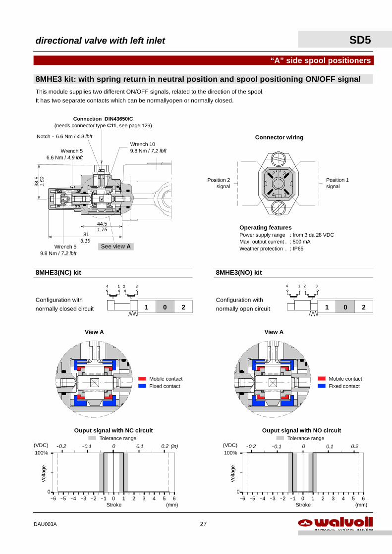
Connection DIN43650/C(needs connector type C11, see page 129)
1.52
1.75
3.19
Operating featuresPower supply range : from 3 da 28 VDCMax. output current : 500 mA.Weather protection : IP65.
4 1
32Position 2
signalPosition 1signal
Connector wiring
“A” side spool positioners
8MHE3 kit: with spring return in neutral position and spool positioning ON/OFF signal
201201
1 2 34 1 2 34
8MHE3(NC) kit 8MHE3(NO) kit
Configuration with
normally closed circuit
Configuration with
normally open circuit
This module supplies two different ON/OFF signals, related to the direction of the spool.
It has two separate contacts which can be normallyopen or normally closed.
View A View A
Mobile contactFixed contact
Mobile contactFixed contact
directional valve with left inlet SD5
27DAU003A
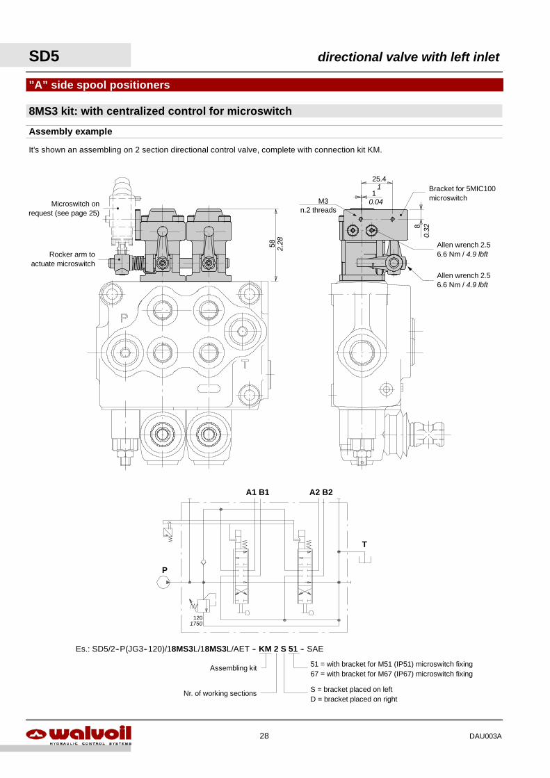
51 = with bracket for M51 (IP51) microswitch fixing67 = with bracket for M67 (IP67) microswitch fixing
S = bracket placed on leftD = bracket placed on right
Assembling kit
Nr. of working sections
M3n.2 threads
58 2.28
”A” side spool positioners
8MS3 kit: with centralized control for microswitch
P
A1 B1 A2 B2
T
Es.: SD5/2--P(JG3--120)/18MS3L/18MS3L/AET -- KM 2 S 51 -- SAE
120
Microswitch onrequest (see page 25)
25.4
1
8
Rocker arm toactuate microswitch
Allen wrench 2.56.6 Nm / 4.9 lbft
Bracket for 5MIC100microswitch
Allen wrench 2.56.6 Nm / 4.9 lbft
1
0.04
0.32
1750
Assembly example
It’s shown an assembling on 2 section directional control valve, complete with connection kit KM.
SD5 directional valve with left inlet
28 DAU003A
1.5
0.06
27.1
58.2
33 62.29
1.30 0.24
Stroke
1.07
7 0.28
∅
18 4
55.5
M4
2.19
0.7140.16
21 4
64
M3
2.52
0.83 0.16 2.5
0.10
30.2
68
25.5 140.551.00
2.68
1.19
Stroke
60.24∅
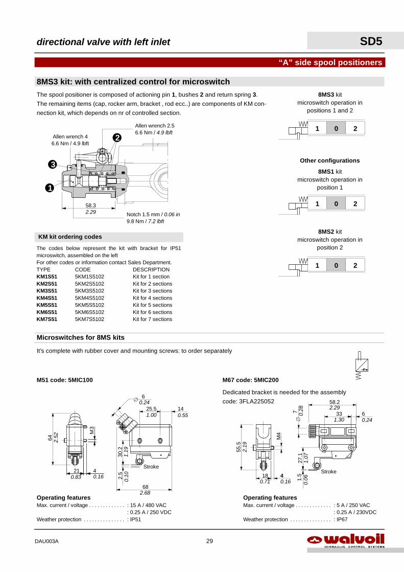
Dedicated bracket is needed for the assembly
code: 3FLA225052
M51 code: 5MIC100 M67 code: 5MIC200
It’s complete with rubber cover and mounting screws: to order separately
58.32.29
8MS3 kit: with centralized control for microswitch
“A” side spool positioners
Microswitches for 8MS kits
Operating featuresMax. current / voltage : 15 A / 480 VAC. . . . . . . . . . . . .
: 0.25 A / 250 VDCWeather protection : IP51. . . . . . . . . . . . . . .
Operating featuresMax. current / voltage : 5 A / 250 VAC. . . . . . . . . . . . .
: 0.25 A / 230VDCWeather protection : IP67. . . . . . . . . . . . . . .
Allen wrench 2.56.6 Nm / 4.9 lbft
Notch 1.5 mm / 0.06 in9.8 Nm / 7.2 lbft
Allen wrench 46.6 Nm / 4.9 lbft
201
201
201
8MS1 kitmicroswitch operation in
position 1
Other configurations
8MS2 kitmicroswitch operation in
position 2
8MS3 kitmicroswitch operation in
positions 1 and 2
The spool positioner is composed of actioning pin 1, bushes 2 and return spring 3.
The remaining items (cap, rocker arm, bracket , rod ecc..) are components of KM con-
nection kit, which depends on nr of controlled section.
KM kit ordering codes
The codes below represent the kit with bracket for IP51microswitch, assembled on the leftFor other codes or information contact Sales Department.TYPE CODE DESCRIPTIONKM1S51 5KM1S5102 Kit for 1 sectionKM2S51 5KM2S5102 Kit for 2 sectionsKM3S51 5KM3S5102 Kit for 3 sectionsKM4S51 5KM4S5102 Kit for 4 sectionsKM5S51 5KM5S5102 Kit for 5 sectionsKM6S51 5KM6S5102 Kit for 6 sectionsKM7S51 5KM7S5102 Kit for 7 sections
1
3
2
directional valve with left inlet SD5
29DAU003A
PACKARD W--PACKmale connector withfemale end
PACKARD W--PACKfemale connectorwith male end
Operating featuresMICROSWITCHMechanical life : 5x10⁵ operations. . . . . . . . . . .Electrical life (resistive load) : 105 oper. -- 7A / 13.5VDC
: 5x10⁴ oper -- 10A / 12VDC: 5x10⁴ per -- 3A / 28VDC
201
8MG1(NO) kit
201
201
Other configurations
8MG2(NO) kit
8MG3(NO) kit
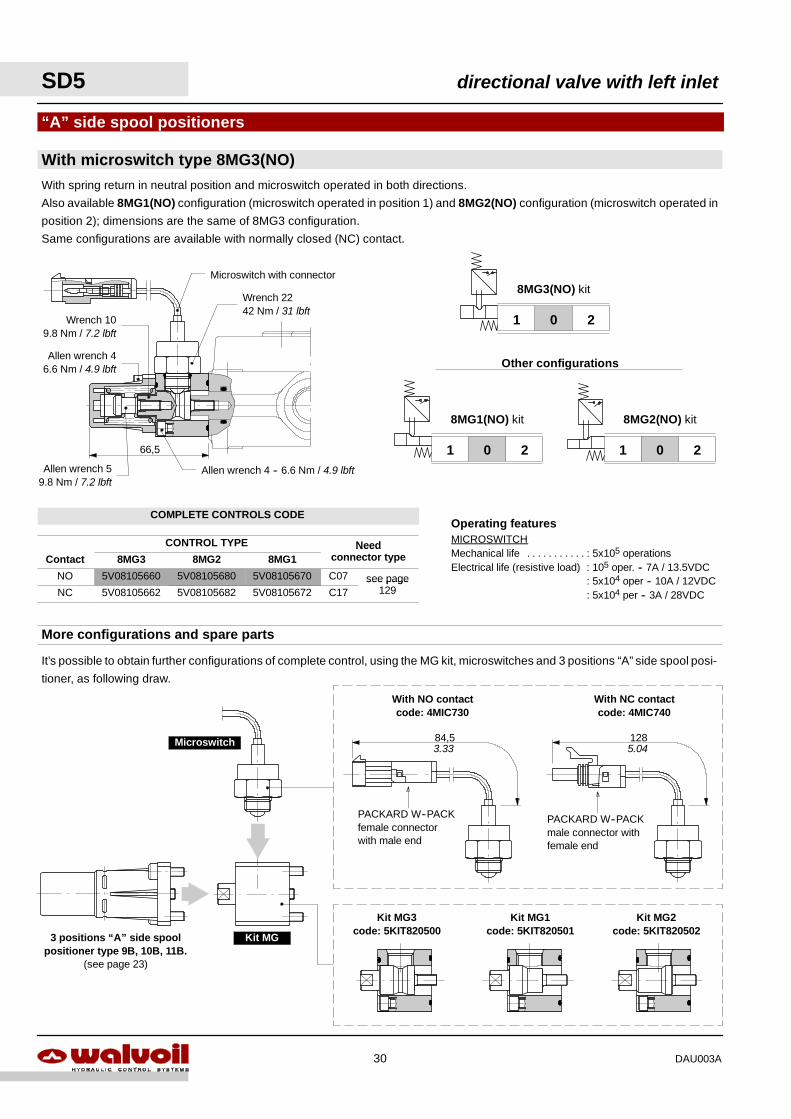
With microswitch type 8MG3(NO)
“A” side spool positioners
With spring return in neutral position and microswitch operated in both directions.
Also available 8MG1(NO) configuration (microswitch operated in position 1) and 8MG2(NO) configuration (microswitch operated in
position 2); dimensions are the same of 8MG3 configuration.
Same configurations are available with normally closed (NC) contact.
66,5
Wrench 2242 Nm / 31 lbft
Allen wrench 59.8 Nm / 7.2 lbft
Allen wrench 4 -- 6.6 Nm / 4.9 lbft
Microswitch with connector
With NO contactcode: 4MIC730
With NC contactcode: 4MIC740
It’s possible to obtain further configurations of complete control, using the MG kit, microswitches and 3 positions “A” side spool posi-
tioner, as following draw.
Kit MG
Microswitch
3 positions “A” side spoolpositioner type 9B, 10B, 11B.
(see page 23)
Kit MG3code: 5KIT820500
Kit MG1code: 5KIT820501
Kit MG2code: 5KIT820502
More configurations and spare parts
84,5 128
Allen wrench 46.6 Nm / 4.9 lbft
Wrench 109.8 Nm / 7.2 lbft
3.33 5.04
SD5 directional valve with left inlet
30 DAU003A
COMPLETE CONTROLS CODE
CONTROL TYPE NeedContact 8MG3 8MG2 8MG1
Needconnector type
NO 5V08105660 5V08105680 5V08105670 C07 see pageNC 5V08105662 5V08105682 5V08105672 C17
see page129
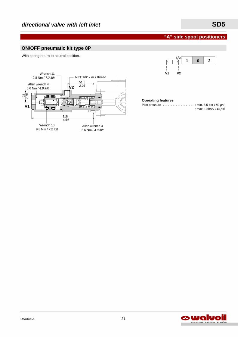
Operating featuresPilot pressure : min. 5.5 bar / 80 psi. . . . . . . . . . . . . . . . . . .
: max. 10 bar / 145 psi
118
23
4.64
0.91
51.5
V1
V2
Allen wrench 46.6 Nm / 4.9 lbft
Wrench 109.8 Nm / 7.2 lbft
Allen wrench 46.6 Nm / 4.9 lbft
Wrench 119.8 Nm / 7.2 lbft NPT 1/8” -- nr.2 thread
ON/OFF pneumatic kit type 8P
“A” side spool positioners
201
V1 V2
With spring return to neutral position.
2.03
directional valve with left inlet SD5
31DAU003A
V1 V2
Wrench 14 -- 9.8 Nm / 7.2 lbft
Special wrench -- 9.8 Nm / 7.2 lbft
Allen wrench 4 -- 6.6 Nm / 4.9 lbft
Wrench 1324 Nm / 17.7 lbft
Wrench 9Allen wrench 46.6 Nm / 4.9 lbft
119
57
42
113.
5
Pg9 431.69 2.24
4.47
1.65
4.68
6Ø
0.24
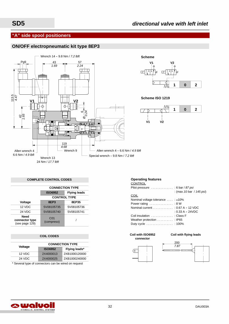
ON/OFF electropneumatic kit type 8EP3
“A” side spool positioners
Operating featuresCONTROLPilot pressure : 6 bar / 87 psi. . . . . . . . . . . . . .
: (max.10 bar / 145 psi)COILNominal voltage tolerance : ±10%. . . .Power rating : 8 W. . . . . . . . . . . . . . .Nominal current : 0.67 A -- 12 VDC. . . . . . . . . . . . .
: 0.33 A -- 24VDCCoil insulation : Class F. . . . . . . . . . . . . .Weather protection : IP65. . . . . . . . . .Duty cycle : 100%. . . . . . . . . . . . . . . . .
Coil with ISO6952connector
Coil with flying leads
200
Scheme ISO 1219
Scheme
201
V1 V2
201
V1 V2
7.87
SD5 directional valve with left inlet
32 DAU003A
COMPLETE CONTROL CODES
CONNECTION TYPE
ISO6952 Flying leads
CONTROL TYPE
Voltage 8EP3 8EP35
12 VDC 5V08105735 5V08105736
24 VDC 5V08105740 5V08105741
Needconnector type(see page 129)
C01(compreso) /
COIL CODES
VoltageCONNECTION TYPE
VoltageISO6952 Flying leads*
12 VDC 2X4000013 2XB1000120000
24 VDC 2X4000025 2XB1000240000
* Several type of connectors can be wired on request

directional valve with left inlet SD5
33DAU003A
COMPLETE CONTROL CODES
CONNECTION TYPE
ISO4400AMP JPT
Deutsch DTISO4400without diodo with diodo
Deutsch DT
CONTROL TYPE
Voltage 8ED3 8ED32 8ED32D 8ED34
12 VDC 5V08105350 5V08105250 5V08105280 5V08105450
24 VDC 5V08105351 5V08105251 5V08105281 5V08105451
Needconnector type(see page 129)
C02 C08 C08 C19
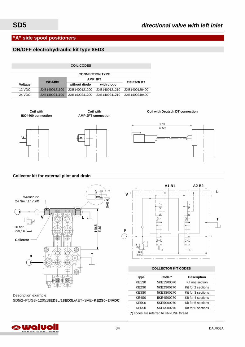
ON/OFF electrohydraulic kit type 8ED3
“A” side spool positioners
With external pilot and drain.
Scheme ISO 1219
Scheme
201
201
V L
LV
1
Operating featuresCONTROLPilot pressure : min. 10 bar / 145 psi. . . . . . . . . . . . . . . . . . .
: max. 50 bar / 725 psiMax backpressure on drain L : 25 bar / 360 psi. . . . . .COILNominal voltage tolerance : ±10%. . . . . . . . .Power rating : 21 W. . . . . . . . . . . . . . . . . . . .Nominal current : 1.75 A -- 12 VDC / 0.87 A -- 24VDC. . . . . . . . . . . . . . . . . .Coil insulation : Class F. . . . . . . . . . . . . . . . . . .Weather protection : IP65. . . . . . . . . . . . . . .Duty cycle : 100%. . . . . . . . . . . . . . . . . . . . . .
Col
lect
or
116
133
Solenoid valve:wrench 24 -- 9.8 Nm / 7.2 lbft
Coil
5942
6.6 Nm4.9 lbft
Allen wrench 4 -- 6.6 Nm / 4.9 lbft
Special wrench -- 9.8 Nm / 7.2 lbft
Wrench 10 -- 24 Nm / 17.7 lbft
Wrench 10
133
139Allen wrench 4 -- 6,6 Nm / 4.9 lbft
5.47
1.65 2.32
5.24
4.57
5.24
ON/OFF electrohydraulic kit type 8ED3
“A” side spool positioners
Collector kit for external pilot and drain
Description example:SD5/2--P(JG3--120)/18ED3L/18ED3L/AET--SAE--KE2S0--24VDC
V
20 bar290 psi
L
Collector
P T
149.
5
P
A1 B1 A2 B2
T
120
VL
Coil withISO4400 connection
Coil withAMP JPT connection
Coil with Deutsch DT connection
1706.69
5.89
1750
SA
E6
Wrench 2224 Nm / 17.7 lbft
SD5 directional valve with left inlet
34 DAU003A
COIL CODES
CONNECTION TYPE
ISO4400AMP JPT
Deutsch DTVoltage
ISO4400without diodo with diodo
Deutsch DT
12 VDC 2XB1400121100 2XB1400121200 2XB1400121210 2XB1400120400
24 VDC 2XB1400241100 2XB1400241200 2XB1400241210 2XB1400240400
COLLECTOR KIT CODES
Type Code * Description
KE1S0 5KE1S00070 Kit one section
KE2S0 5KE2S00270 Kit for 2 sections
KE3S0 5KE3S00270 Kit for 3 sections
KE4S0 5KE4S00270 Kit for 4 sections
KE5S0 5KE5S00270 Kit for 5 sections
KE6S0 5KE6S00270 Kit for 6 sections
(*) codes are referred to UN--UNF thread
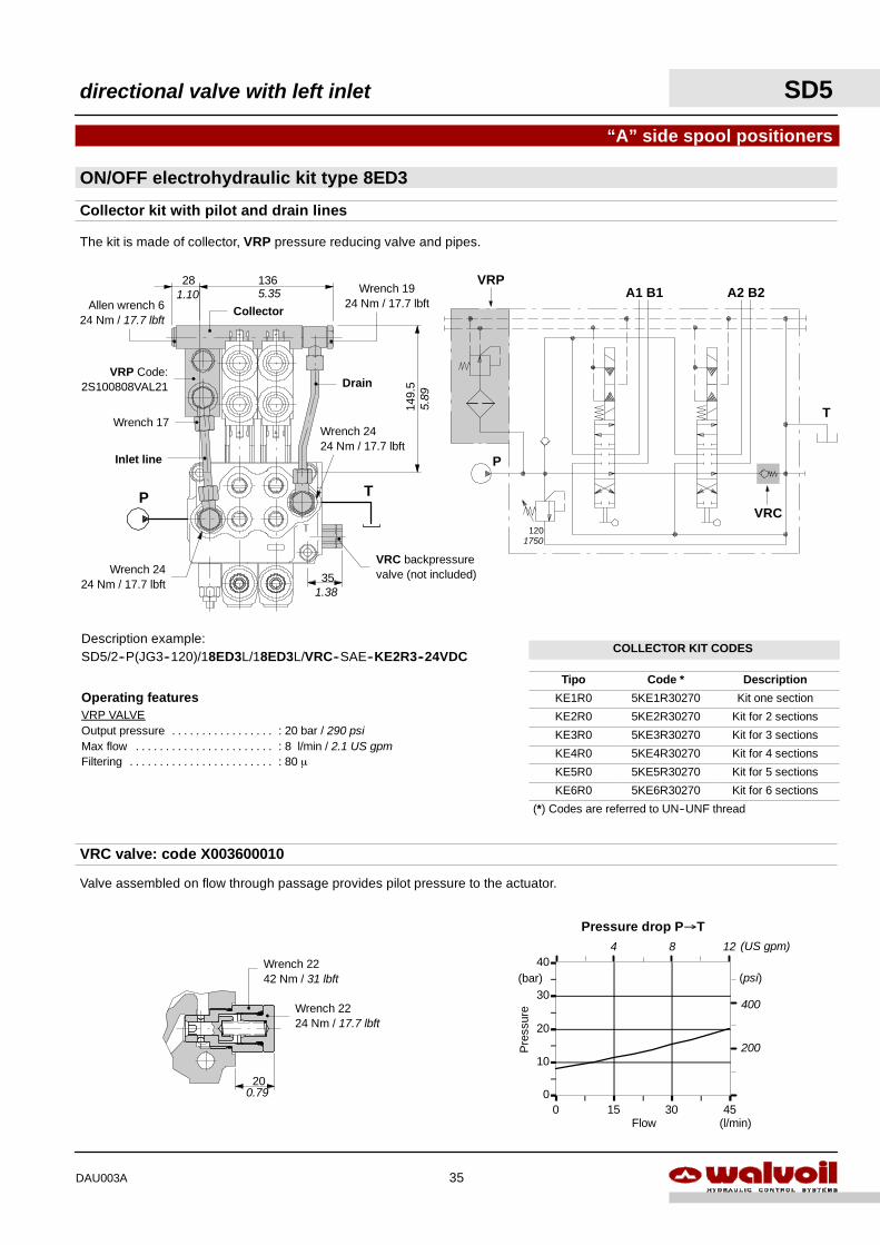
Pressure drop P→T
0
10
20
30
40
0 15 30 45Flow
Pre
ssur
e
(l/min)
(bar)
400
200
(psi)
4 8 (US gpm)12
200.79
Wrench 2224 Nm / 17.7 lbft
Wrench 2242 Nm / 31 lbft
“A” side spool positioners
Collector kit with pilot and drain lines
The kit is made of collector, VRP pressure reducing valve and pipes.
Description example:SD5/2--P(JG3--120)/18ED3L/18ED3L/VRC--SAE--KE2R3--24VDC
ON/OFF electrohydraulic kit type 8ED3
Operating featuresVRP VALVEOutput pressure : 20 bar / 290 psi. . . . . . . . . . . . . . . . .Max flow : 8 l/min / 2.1 US gpm. . . . . . . . . . . . . . . . . . . . . . .Filtering : 80 µ. . . . . . . . . . . . . . . . . . . . . . . .
149.
5
Inlet line
Drain
TP
Collector
VRP Code:2S100808VAL21
VRC backpressurevalve (not included)
Wrench 17
Wrench 1924 Nm / 17.7 lbft
35
13628
Wrench 2424 Nm / 17.7 lbft
P
A1 B1 A2 B2
T
120
VRP
VRC
VRC valve: code X003600010
Valve assembled on flow through passage provides pilot pressure to the actuator.
Allen wrench 624 Nm / 17.7 lbft
Wrench 2424 Nm / 17.7 lbft
5.89
1.10 5.35
1.38
1750
directional valve with left inlet SD5
35DAU003A
COLLECTOR KIT CODES
Tipo Code * Description
KE1R0 5KE1R30270 Kit one section
KE2R0 5KE2R30270 Kit for 2 sections
KE3R0 5KE3R30270 Kit for 3 sections
KE4R0 5KE4R30270 Kit for 4 sections
KE5R0 5KE5R30270 Kit for 5 sections
KE6R0 5KE6R30270 Kit for 6 sections
(*) Codes are referred to UN--UNF thread
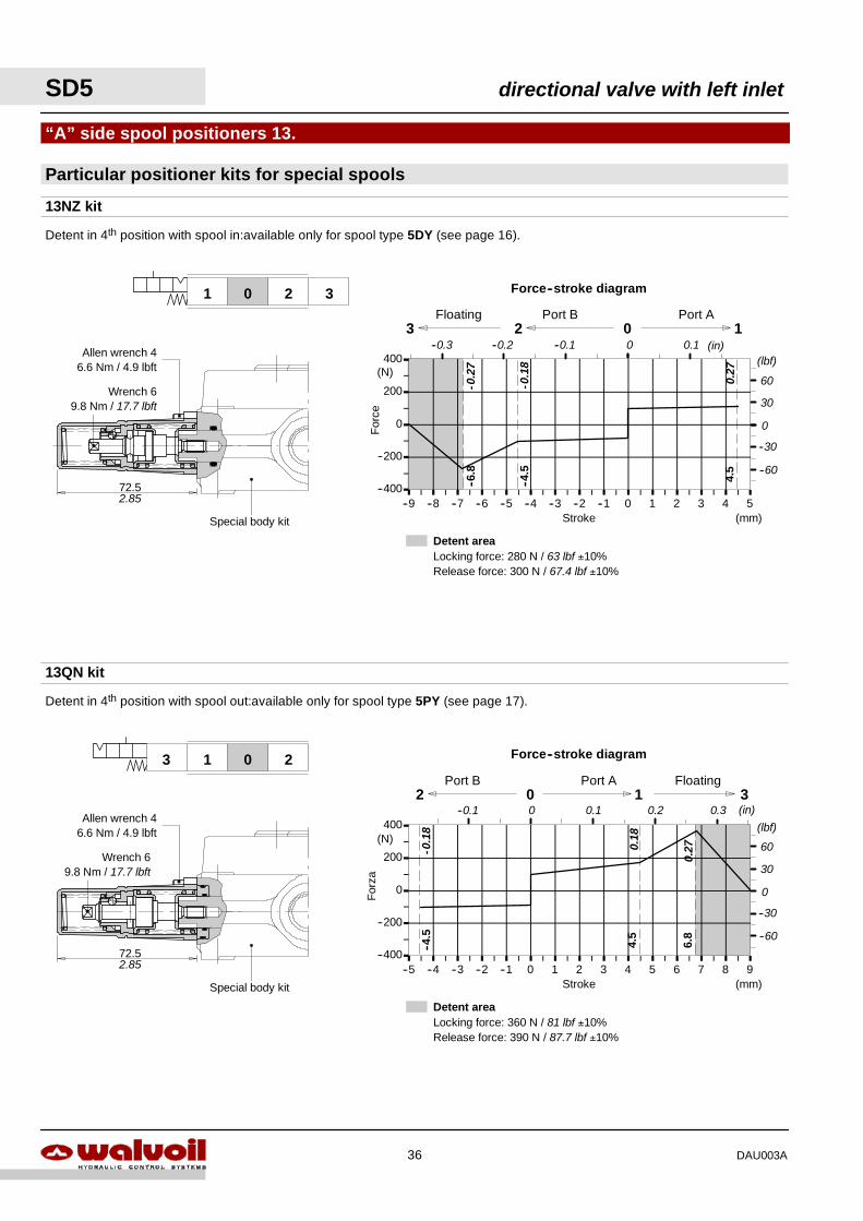
Detent areaLocking force: 360 N / 81 lbf ±10%Release force: 390 N / 87.7 lbf ±10%
--400
--200
0
200
400
--5 --4 --3 --2 --1 0 1 2 3 4 5 6 7 8 9Stroke
For
za
(mm)
(N)
Force--stroke diagram
2 0 1Port B Port A
3
--4.5
4.5
Floating
72.5
Allen wrench 46.6 Nm / 4.9 lbft
Wrench 69.8 Nm / 17.7 lbft
Special body kit
Particular positioner kits for special spools
“A” side spool positioners 13.
13NZ kit
Detent areaLocking force: 280 N / 63 lbf ±10%Release force: 300 N / 67.4 lbf ±10%
201 3
Detent in 4th position with spool in:available only for spool type 5DY (see page 16).
13QN kit
--400
--200
0
200
400
--9 --8 --7 --6 --5 --4 --3 --2 --1 0 1 2 3 4 5Stroke
For
ce
(mm)
(N)
Force--stroke diagram
2 0 1Port B Port A
4.5
--4.5
3Floating
72.5
Special body kit
Detent in 4th position with spool out:available only for spool type 5PY (see page 17).
2013
--6.8
6.8
(in)
60
30
(lbf)--0.1--0.2 0
0
--60
--30
--0.3 0.1
-0.1
8
-0.2
7
0.27
2.85
60
30
(lbf)
0
--60
--30
(in)0.1 0.20 0.3--0.1
-0.1
8
0.18
0.27
Allen wrench 46.6 Nm / 4.9 lbft
Wrench 69.8 Nm / 17.7 lbft
2.85
SD5 directional valve with left inlet
36 DAU003A
directional valve with left inlet SD5
37DAU003A
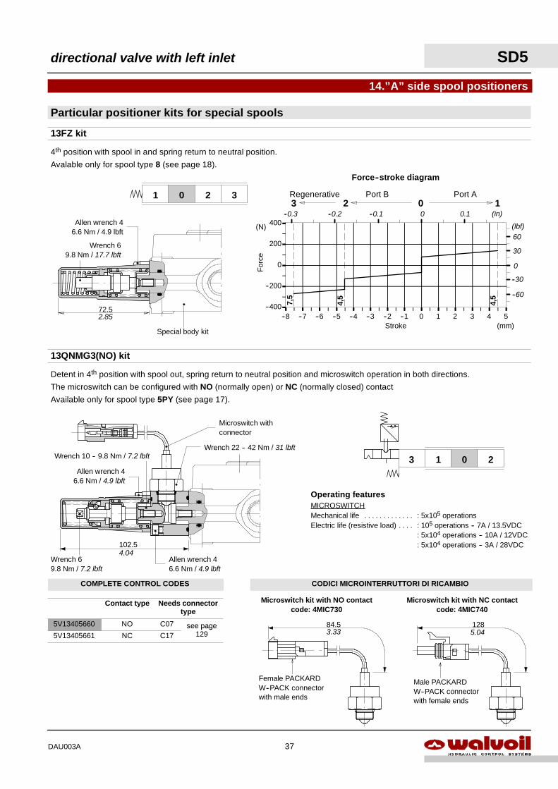
COMPLETE CONTROL CODES CODICI MICROINTERRUTTORI DI RICAMBIO
Contact type Needs connectortype
5V13405660 NO C07 see page5V13405661 NC C17
see page129
Particular positioner kits for special spools
14.”A” side spool positioners
Detent in 4th position with spool out, spring return to neutral position and microswitch operation in both directions.
The microswitch can be configured with NO (normally open) or NC (normally closed) contact
Available only for spool type 5PY (see page 17).
Operating featuresMICROSWITCHMechanical life : 5x10⁵ operations. . . . . . . . . . . . .Electric life (resistive load) : 105 operations -- 7A / 13.5VDC. . . .
: 5x10⁴ operations -- 10A / 12VDC: 5x10⁴ operations -- 3A / 28VDC102.5
Wrench 22 -- 42 Nm / 31 lbft
Allen wrench 46.6 Nm / 4.9 lbft
Microswitch withconnector
13QNMG3(NO) kit
Wrench 69.8 Nm / 7.2 lbft
Allen wrench 46.6 Nm / 4.9 lbft
Wrench 10 -- 9.8 Nm / 7.2 lbft 2013
Microswitch kit with NO contactcode: 4MIC730
Female PACKARDW--PACK connectorwith male ends
Microswitch kit with NC contactcode: 4MIC740
Male PACKARDW--PACK connectorwith female ends
13FZ kit
72.5
Special body kit
201 3
4th position with spool in and spring return to neutral position.
Avalable only for spool type 8 (see page 18).
--400
--200
0
200
400
--8 --7 --6 --5 --4 --3 --2 --1 0 1 2 3 4 5Stroke
For
ce
(mm)
(N)
Force--stroke diagram
2 0 1Port B Port A
4,5
7,5
3Regenerative
4,5
84.5 128
Allen wrench 46.6 Nm / 4.9 lbft
Wrench 69.8 Nm / 17.7 lbft
2.85
(in)
60
30
(lbf)
--0.1--0.2 0
0
--60
--30
--0.3 0.1
4.04
3.33 5.04
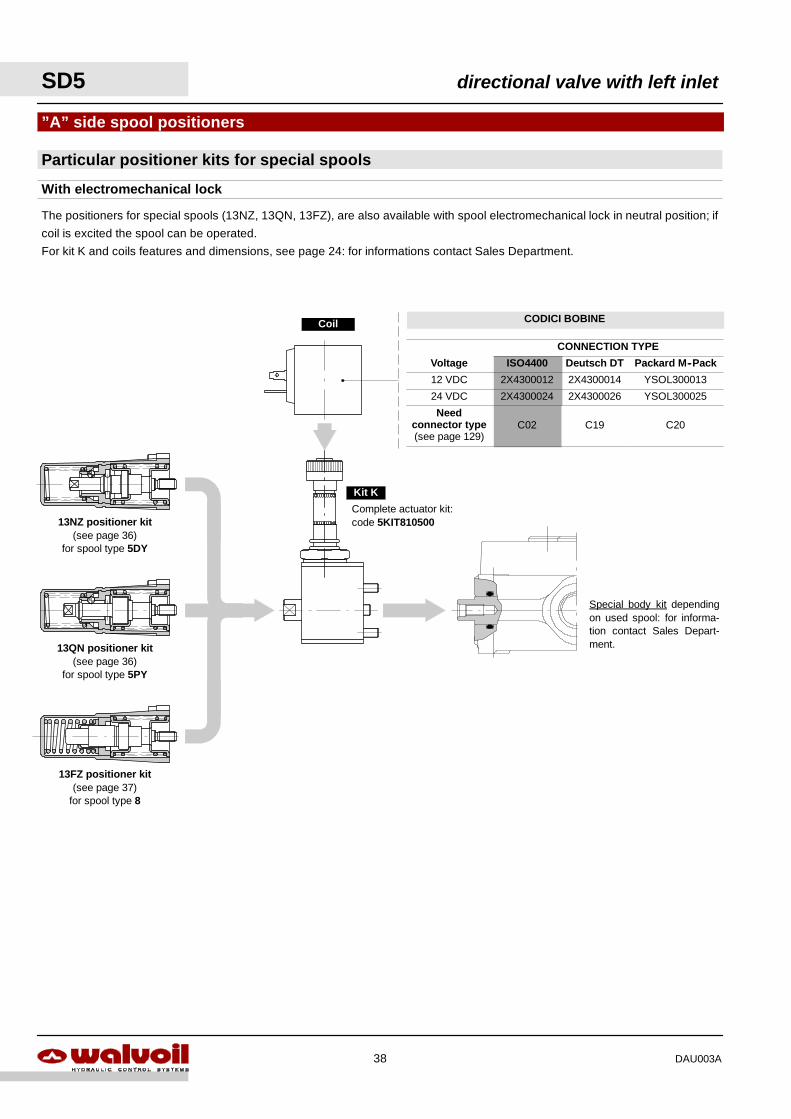
”A” side spool positioners
The positioners for special spools (13NZ, 13QN, 13FZ), are also available with spool electromechanical lock in neutral position; if
coil is excited the spool can be operated.
For kit K and coils features and dimensions, see page 24: for informations contact Sales Department.
Particular positioner kits for special spools
With electromechanical lock
Special body kit dependingon used spool: for informa-tion contact Sales Depart-ment.
Coil
Kit K
13NZ positioner kit(see page 36)
for spool type 5DY
13QN positioner kit(see page 36)
for spool type 5PY
13FZ positioner kit(see page 37)
for spool type 8
Complete actuator kit:code 5KIT810500
SD5 directional valve with left inlet
38 DAU003A
CODICI BOBINE
CONNECTION TYPE
Voltage ISO4400 Deutsch DT Packard M--Pack
12 VDC 2X4300012 2X4300014 YSOL300013
24 VDC 2X4300024 2X4300026 YSOL300025
Needconnector type(see page 129)
C02 C19 C20
20
441.73
0.79
Allen wrench 2.5
Wrench 1324 Nm / 17.7 lbft
20
44
24.5
20
53.7 65
.5
66max
M8
0.79
2.11 2.
580.
96
0.79
1.73
2.60
Allen wrench 4 -- 6.6 Nm / 4.9 lbft
M8
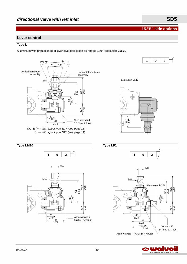
Type LM10
M10
201
M10
54
71.5
24.5
20 0.79
2.13
2.82
0.96
Allen wrench 46.6 Nm / 4.9 lbft
NOTE (*) -- With spool type 5DY (see page 16)(**) -- With spool type 5PY (see page 17)
29.2
41
1.15
1.61
Horizontal handleverassembly
Allen wrench 46.6 Nm / 4.9 lbft
M8
20
44
24.
20
53.7 65
.5
1.73
0.79
0.79
2.11 2.
580.
965
(**) (*)
Vertical handleverassembly
Lever control
15.”B” side options
Alluminium with protection boot lever pivot box; it can be rotated 180° (execution L180).
201
Execution L180
Type L
Type LF1
201
directional valve with left inlet SD5
39DAU003A
0.20
201
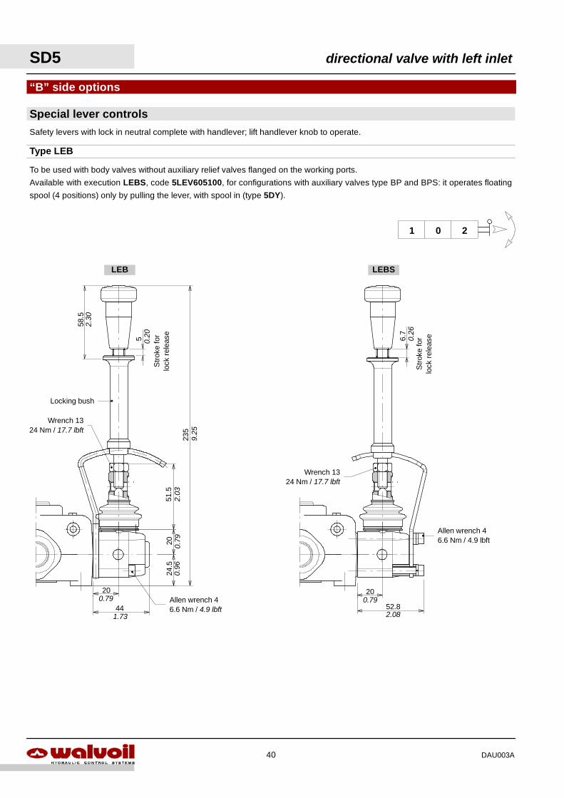
Special lever controls
“B” side options
Safety levers with lock in neutral complete with handlever; lift handlever knob to operate.
Type LEB
24.5
2051
.5
235
Allen wrench 46.6 Nm / 4.9 lbft
Wrench 1324 Nm / 17.7 lbft
Locking bush
5
Str
oke
for
lock
rele
ase
52.8
20
To be used with body valves without auxiliary relief valves flanged on the working ports.
Available with execution LEBS, code 5LEV605100, for configurations with auxiliary valves type BP and BPS: it operates floating
spool (4 positions) only by pulling the lever, with spool in (type 5DY).
6.7
Allen wrench 46.6 Nm / 4.9 lbft
58.5
Wrench 1324 Nm / 17.7 lbft
LEBSLEB
44
200.79
1.73
2.03
0.79
0.96
9.25
2.30
Str
oke
for
lock
rele
ase0.26
0.79
2.08
SD5 directional valve with left inlet
40 DAU003A
68.52.70
Allen wrench 83 Nm / 2.2 lbft
Allen wrench 4 -- 6.6 Nm / 4.9 lbft
Type SLC
201
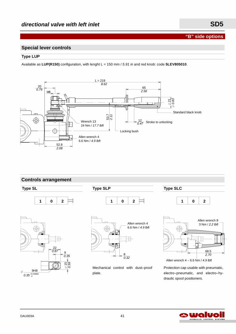
Protection cap usable with pneumatic,
electro--pneumatic, and electro--hy-
draulic spool positioners.
Available as LUP(R150) configuration, with lenght L = 150 mm / 5.91 in and red knob: code 5LEV805010.
L = 219
52.8
53.7
12
M8
21
6520
Stroke to unlocking
Locking bush
8.62
2.08
2.11
0.79 2.56
0.47
Allen wrench 46.6 Nm / 4.9 lbft
Wrench 1324 Nm / 17.7 lbft
0.83
Standard black knob
“B” side options
Controls arrangement
Special lever controls
Type LUP
15
9
22
9H8
0.35
0.87
0.59
0.35 +0.008660
201
Type SL Type SLP
201
Mechanical control with dust--proof
plate.
Allen wrench 46.6 Nm / 4.9 lbft
80.32
directional valve with left inlet SD5
41DAU003A
81
Allen wrench 4 -- 6.6 Nm / 4.9 lbft
Wrench 10 -- 9.8 Nm / 7.2 lbft
Wrench 24 -- 24 Nm / 17.7 lbft
Flexible cable
3.19
“B” side options
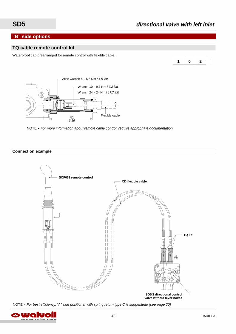
Waterproof cap prearranged for remote control with flexible cable.
NOTE -- For more information about remote cable control, require appropriate documentation.
201
TQ cable remote control kit
NOTE -- For best efficiency, “A” side positioner with spring return type C is suggestedo (see page 20)
Connection example
SD5/2 directional controlvalve without lever boxes
SCF031 remote controlCD flexible cable
TQ kit
SD5 directional valve with left inlet
42 DAU003A
A2
A1
B2
B1
A2--A1A2--B1
B2--A1B2--B1
A1
A2
B1
B2
A1--A2 A1--B2
B1--A2 B1--B2
B2
A1
A2
B1
B2--A1B2--B1
A2--A1A2--B1
B1
A2
A1
B2
B1--A2 B1--B2
A1--A2 A1--B2
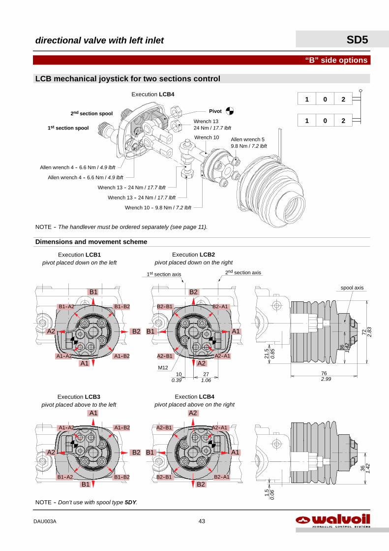
NOTE -- Don’t use with spool type 5DY.
Execution LCB3pivot placed above to the left
Exection LCB4pivot placed above on the right
Execution LCB1pivot placed down on the left
Execution LCB2pivot placed down on the right
NOTE -- The handlever must be ordered separately (see page 11).
LCB mechanical joystick for two sections control
201
201
Dimensions and movement scheme
M12
1st section spool
2nd section spool Pivot
Allen wrench 59.8 Nm / 7.2 lbft
Wrench 10 -- 9.8 Nm / 7.2 lbft
Wrench 13 -- 24 Nm / 17.7 lbft
Wrench 13 -- 24 Nm / 17.7 lbft
Wrench 10
Wrench 1324 Nm / 17.7 lbft
Allen wrench 4 -- 6.6 Nm / 4.9 lbft
Allen wrench 4 -- 6.6 Nm / 4.9 lbft
Execution LCB4
2nd section axis1st section axis
10 270.39 1.06
36
72
76
21.5
0.85
2.99
2.83
1.42
spool axis
1.5
36 1.42
0.06
“B” side options
directional valve with left inlet SD5
43DAU003A
4.
Complete controls14.
2.
3.
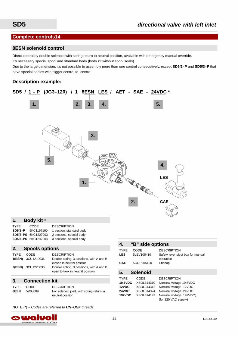
SD5 / 1 -- P (JG3--120) / 1 8ESN LES / AET -- SAE -- 24VDC *
Description example:
2. 3.
5.
LES
CAE
4.1.
2. Spools optionsTYPE CODE DESCRIPTION1(ESN) 3CU1210036 Double acting, 3 positions, with A and B
closed in neutral position2(ESN) 3CU1225036 Double acting, 3 positions, with A and B
open to tank in neutral position
3. Connection kitTYPE CODE DESCRIPTION8ESN 5V08009 For solenoid joint, with spring return in
neutral position
4. “B” side optionsTYPE CODE DESCRIPTIONLES 5LEV105410 Safety lever pivot box for manual
operationCAE 5COP205100 Endcap
5. SolenoidTYPE CODE DESCRIPTION10.5VDC XSOL314310 Nominal voltage 10.5VDC12VDC XSOL314312 Nominal voltage 12VDC24VDC XSOL314324 Nominal voltage 24VDC192VDC XSOL314192 Nominal voltage 192VDC;
(for 220 VAC supply)
5.
1.
1. Body kit *TYPE CODE DESCRIPTIONSD5/1--P 5KC1197100 1 section, standard bodySD5/2--PS 5KC1227003 2 sections, special bodySD5/3--PS 5KC1247004 3 sections, special body
NOTE (*) -- Codes are referred to UN- UNF threads.
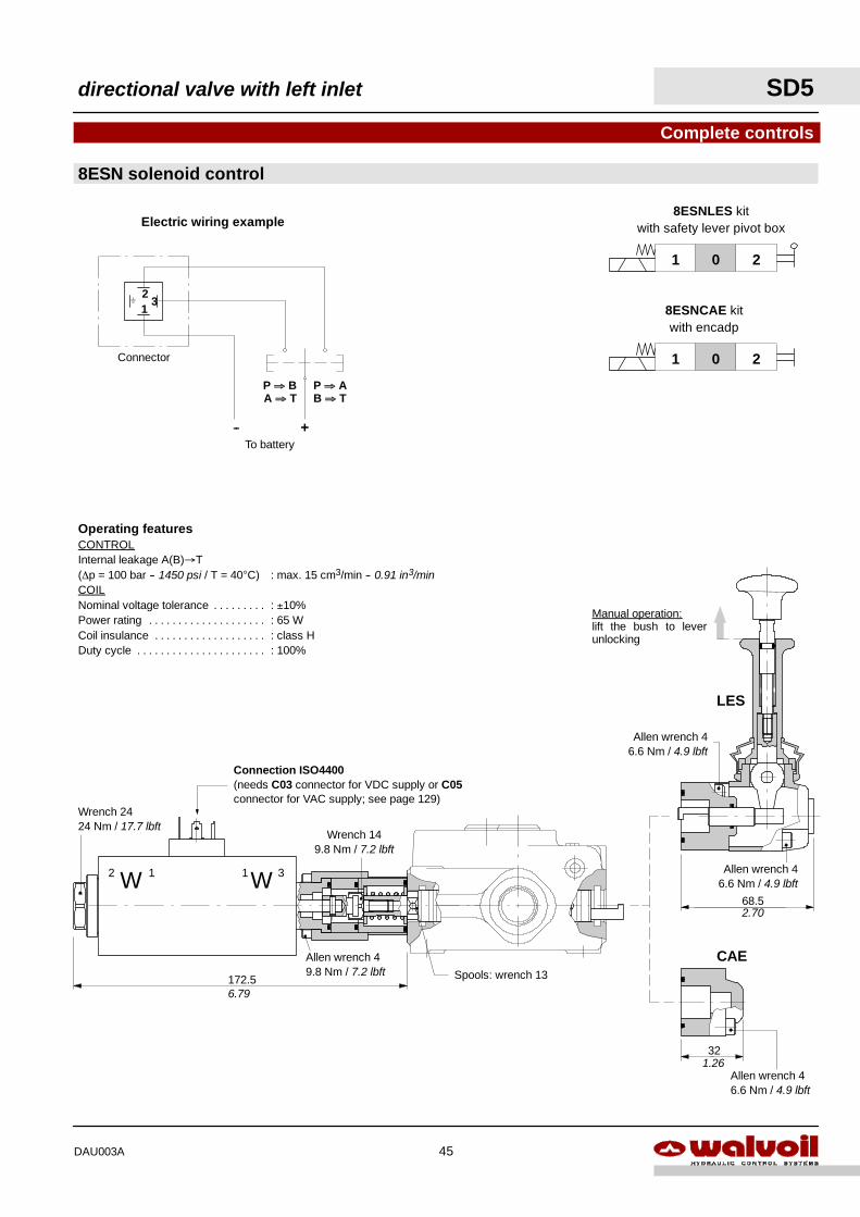
8ESN solenoid controlDirect control by double solenoid with spring return to neutral position, available with emergency manual override.
It’s necessary special spool and standard body (body kit without spool seals).
Due to the large dimension, it’s not possible to assembly more than one control consecutively, except SD5/2--P and SD5/3--P that
have special bodies with bigger centre--to--centre.
SD5 directional valve with left inlet
44 DAU003A
201
8ESNCAE kitwith encadp
201
8ESNLES kitwith safety lever pivot box
312
+--
P ⇒ AB ⇒ T
P ⇒ BA ⇒ T
Electric wiring example
To battery
Connector
Operating featuresCONTROLInternal leakage A(B)→T(∆p = 100 bar -- 1450 psi / T = 40°C) : max. 15 cm3/min -- 0.91 in3/minCOILNominal voltage tolerance : ±10%. . . . . . . . .Power rating : 65 W. . . . . . . . . . . . . . . . . . . .Coil insulance : class H. . . . . . . . . . . . . . . . . . .Duty cycle : 100%. . . . . . . . . . . . . . . . . . . . . .
8ESN solenoid control
Complete controls
3112 WW
172.5 Spools: wrench 13
Allen wrench 49.8 Nm / 7.2 lbft
Wrench 149.8 Nm / 7.2 lbft
Manual operation:lift the bush to leverunlocking
32
68.5
Wrench 2424 Nm / 17.7 lbft
Allen wrench 46.6 Nm / 4.9 lbft
Allen wrench 46.6 Nm / 4.9 lbft
LES
CAE
Connection ISO4400(needs C03 connector for VDC supply or C05connector for VAC supply; see page 129)
6.79
2.70
Allen wrench 46.6 Nm / 4.9 lbft
1.26
directional valve with left inlet SD5
45DAU003A
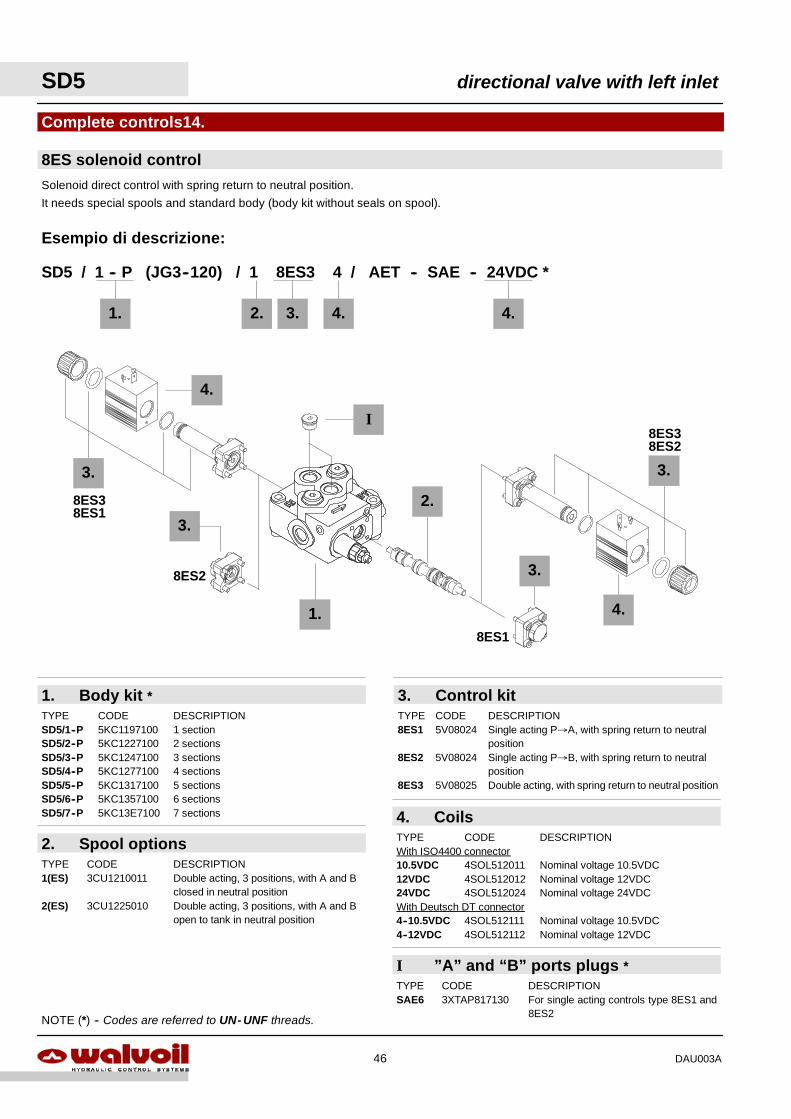
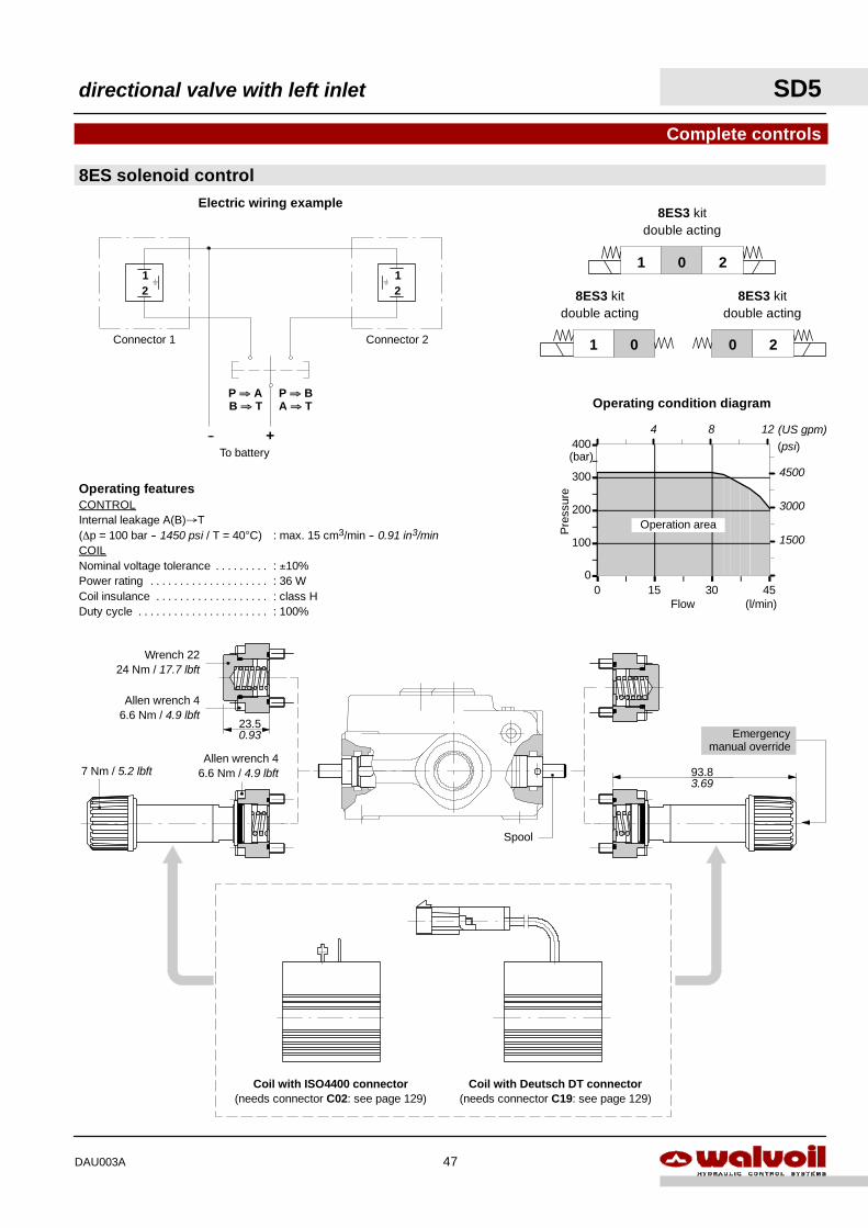
8ES solenoid control
Complete controls14.
Solenoid direct control with spring return to neutral position.
It needs special spools and standard body (body kit without seals on spool).
1.
2.
SD5 / 1 -- P (JG3--120) / 1 8ES3 4 / AET -- SAE -- 24VDC *
Esempio di descrizione:
1. 2.
8ES3
8ES1
3. 4.
4.
8ES3
8ES2
8ES1
8ES2
4.
2. Spool optionsTYPE CODE DESCRIPTION1(ES) 3CU1210011 Double acting, 3 positions, with A and B
closed in neutral position2(ES) 3CU1225010 Double acting, 3 positions, with A and B
open to tank in neutral position
3. Control kitTYPE CODE DESCRIPTION8ES1 5V08024 Single acting P→A, with spring return to neutral
position8ES2 5V08024 Single acting P→B, with spring return to neutral
position8ES3 5V08025 Double acting, with spring return to neutral position
4. CoilsTYPE CODE DESCRIPTIONWith ISO4400 connector10.5VDC 4SOL512011 Nominal voltage 10.5VDC12VDC 4SOL512012 Nominal voltage 12VDC24VDC 4SOL512024 Nominal voltage 24VDCWith Deutsch DT connector4--10.5VDC 4SOL512111 Nominal voltage 10.5VDC4--12VDC 4SOL512112 Nominal voltage 12VDC
1. Body kit *TYPE CODE DESCRIPTIONSD5/1--P 5KC1197100 1 sectionSD5/2--P 5KC1227100 2 sectionsSD5/3--P 5KC1247100 3 sectionsSD5/4--P 5KC1277100 4 sectionsSD5/5--P 5KC1317100 5 sectionsSD5/6--P 5KC1357100 6 sectionsSD5/7--P 5KC13E7100 7 sections
I
I ”A” and “B” ports plugs *TYPE CODE DESCRIPTIONSAE6 3XTAP817130 For single acting controls type 8ES1 and
8ES2NOTE (*) -- Codes are referred to UN- UNF threads.
3.
3.
3.3.
4.
SD5 directional valve with left inlet
46 DAU003A
P ⇒ BA ⇒ T
P ⇒ AB ⇒ T
+--
Electric wiring example
To battery
Connector 1
21
Connector 2
21
Operating featuresCONTROLInternal leakage A(B)→T(∆p = 100 bar -- 1450 psi / T = 40°C) : max. 15 cm3/min -- 0.91 in3/minCOILNominal voltage tolerance : ±10%. . . . . . . . .Power rating : 36 W. . . . . . . . . . . . . . . . . . . .Coil insulance : class H. . . . . . . . . . . . . . . . . . .Duty cycle : 100%. . . . . . . . . . . . . . . . . . . . . .
8ES solenoid control
Complete controls
201
01
8ES3 kitdouble acting
8ES3 kitdouble acting
20
8ES3 kitdouble acting
93.8
23.5
Allen wrench 46.6 Nm / 4.9 lbft
Wrench 2224 Nm / 17.7 lbft
7 Nm / 5.2 lbft
Spool
Emergencymanual override
Allen wrench 46.6 Nm / 4.9 lbft
Coil with Deutsch DT connector(needs connector C19: see page 129)
Coil with ISO4400 connector(needs connector C02: see page 129)
0
100
200
300
400
0 15 30 45
Operating condition diagram
Flow
Pre
ssur
e
(l/min)
(bar)
Operation area
(psi)
4500
3000
1500
0.93
3.69
4 8 (US gpm)12
directional valve with left inlet SD5
47DAU003A
PT
A1 A2
B1 B2
VA1 VA2
VB1 VB2
Spool control curvetype 026 with step
0
10
20
30
0,0 2,0 4,0 6,0
6.5
14
0.85
Pilo
tpre
ssur
e
Stroke (mm)
(bar)
7.25
0.1 0.2
100
200
300
(psi)(in)
400
0.3
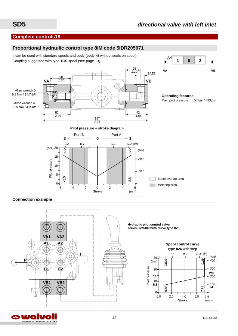
Proportional hydraulic control type 8IM code 5IDR205071
Complete controls18.
201
VA VB
52
197
28
Allen wrench 59.8 Nm / 17.7 lbft
VA VB
42
Operating featuresMax. pilot pressure : 50 bar / 730 psi.
Connection example
Hydraulic pilot control valveseries SVM400 with curve type 026
Pilot pressure -- stroke diagram
0
5
10
15
20
--6 --4 --2 0 2 4 6
2 0 1Port B Port A
Metering area
Spool overlap area
Pilo
tpre
ssur
e
Stroke (mm)
(bar)
5.5
--5.5
0.1 0.2 (in)--0.1--0.2
100
200
(psi)
It can be used with standard spools and body (body kit without seals on spool).
Coupling suggested with type 1CS spool (see page 13).
2.05
7.76
1.65
1.10
--5.5
--0.2
2
0.22
0.03
3
0.29
203
94
7.6
381.50
Allen wrench 46.6 Nm / 4.9 lbft
SAE6
SD5 directional valve with left inlet
48 DAU003A
31
SA
E6
X
Wrench 2442 Nm / 31 lbft
1.22
Wrench 2224 Nm / 17.7 lbft
2.5
Allen wrench 8 --42 Nm / 31 lbft
0.10
C
23.50.93
Wrench 27 --42 Nm / 31 lbft
SA
E8
0
3
6
9
12
0 10 20 30 40
Pressure drop curve
Flow
Pre
ssur
e
(l/min)
(bar)
45
(psi)150
100
50
4 8 (US gpm)12
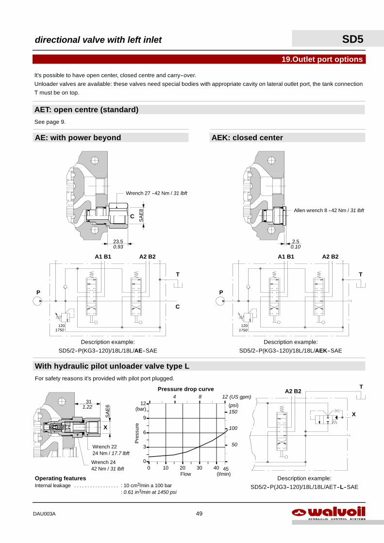
Operating featuresInternal leakage : 10 cm3/min a 100 bar. . . . . . . . . . . . . . . . .
: 0.61 in3/min at 1450 psi
It’s possible to have open center, closed centre and carry--over.
Unloader valves are available: these valves need special bodies with appropriate cavity on lateral outlet port, the tank connection
T must be on top.
AE: with power beyond
AET: open centre (standard)
19.Outlet port options
See page 9.
Description example:
SD5/2--P(KG3--120)/18L/18L/AE--SAE
P
A1 B1 A2 B2
T
120
Description example:
SD5/2--P(KG3--120)/18L/18L/AEK--SAE
P
A1 B1 A2 B2
T
120
C
With hydraulic pilot unloader valve type LFor safety reasons it’s provided with pilot port plugged.
A2 B2T
Description example:
SD5/2--P(JG3--120)/18L/18L/AET--L--SAE
X
AEK: closed center
1750 1750
directional valve with left inlet SD5
49DAU003A
0
5
10
15
20
25
0 20 40 60
Pressure drop
Flow
Pre
ssur
e
(l/min)
(bar)(psi)
300
200
100
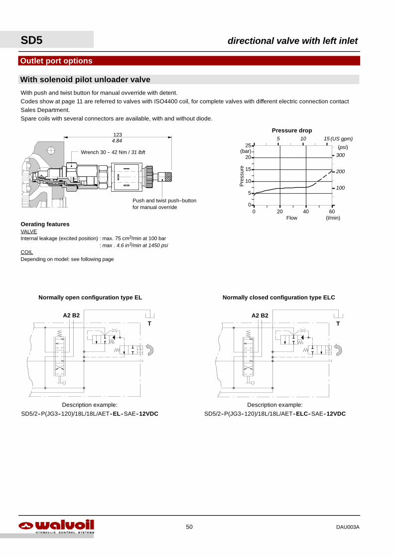
With solenoid pilot unloader valve
Outlet port options
Oerating featuresVALVEInternal leakage (excited position) : max. 75 cm3/min at 100 bar
: max . 4.6 in3/min at 1450 psiCOILDepending on model: see following page
A2 B2T
Description example:
SD5/2--P(JG3--120)/18L/18L/AET--EL--SAE--12VDC
123
A2 B2T
Normally open configuration type EL Normally closed configuration type ELC
Description example:
SD5/2--P(JG3--120)/18L/18L/AET--ELC--SAE--12VDC
With push and twist button for manual ovverride with detent.Codes show at page 11 are referred to valves with ISO4400 coil, for complete valves with different electric connection contactSales Department.Spare coils with several connectors are available, with and without diode.
Push and twist push--buttonfor manual override
Wrench 30 -- 42 Nm / 31 lbft
4.84 5 10 15 (US gpm)
SD5 directional valve with left inlet
50 DAU003A
Allen wrench 624 Nm / 17.7 lbft
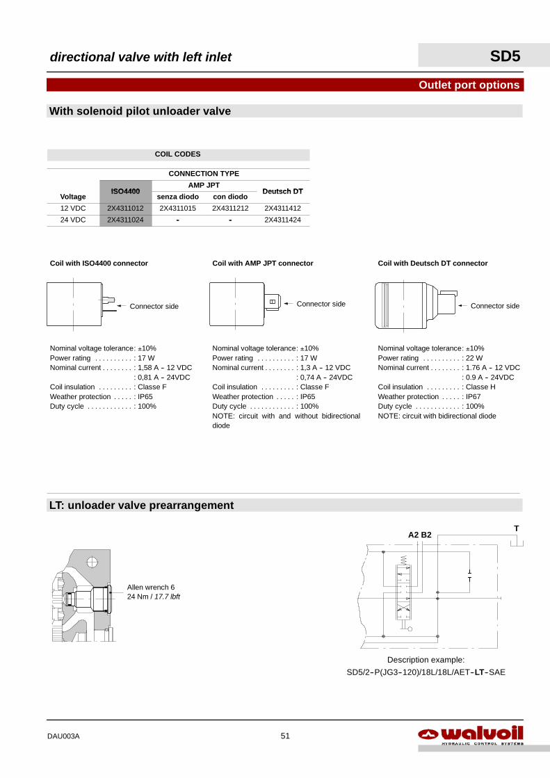
Nominal voltage tolerance: ±10%Power rating : 22 W. . . . . . . . . .Nominal current : 1.76 A -- 12 VDC. . . . . . . .
: 0.9 A -- 24VDCCoil insulation : Classe H. . . . . . . . .Weather protection : IP67. . . . .Duty cycle : 100%. . . . . . . . . . . .NOTE: circuit with bidirectional diode
Coil with Deutsch DT connector
Connector side
With solenoid pilot unloader valve
Outlet port options
A2 B2T
Description example:
SD5/2--P(JG3--120)/18L/18L/AET--LT--SAE
LT: unloader valve prearrangement
Nominal voltage tolerance: ±10%Power rating : 17 W. . . . . . . . . .Nominal current : 1,58 A -- 12 VDC. . . . . . . .
: 0,81 A -- 24VDCCoil insulation : Classe F. . . . . . . . .Weather protection : IP65. . . . .Duty cycle : 100%. . . . . . . . . . . .
Coil with ISO4400 connector
Connector side
Nominal voltage tolerance: ±10%Power rating : 17 W. . . . . . . . . .Nominal current : 1,3 A -- 12 VDC. . . . . . . .
: 0,74 A -- 24VDCCoil insulation : Classe F. . . . . . . . .Weather protection : IP65. . . . .Duty cycle : 100%. . . . . . . . . . . .NOTE: circuit with and without bidirectionaldiode
Coil with AMP JPT connector
Connector side
directional valve with left inlet SD5
51DAU003A
COIL CODES
CONNECTION TYPE
ISO4400AMP JPT
Deutsch DTVoltage
ISO4400senza diodo con diodo
Deutsch DT
12 VDC 2X4311012 2X4311015 2X4311212 2X4311412
24 VDC 2X4311024 -- -- 2X4311424
SD5 directional valve with left inlet
52 DAU003A
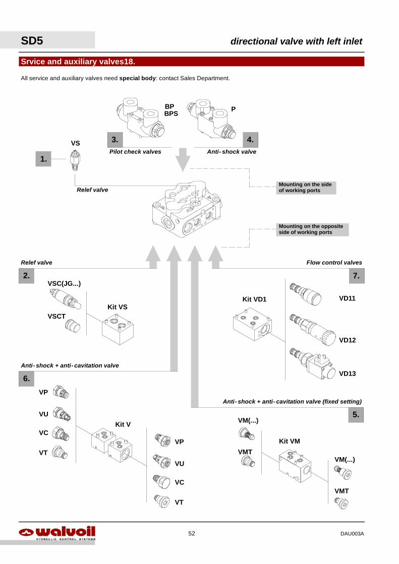
Anti- shock + anti- cavitation valve (fixed setting)
Flow control valves
Anti- shock + anti- cavitation valve
Relef valve
Relef valve
Pilot check valves Anti- shock valve
5.
4.
1.
2.
3.
Srvice and auxiliary valves18.
6.
7.
BPSBP P
VS
Kit VM
VD13
All service and auxiliary valves need special body: contact Sales Department.
VD12
VD11Kit VD1
VM(...)
VMT
VM(...)
VMT
VSC(JG...)
VSCTKit VS
Kit V
VP
VU
VC
VT
VP
VU
VC
VT
Mounting on the sideof working ports
Mounting on the oppositeside of working ports
directional valve with left inlet SD5
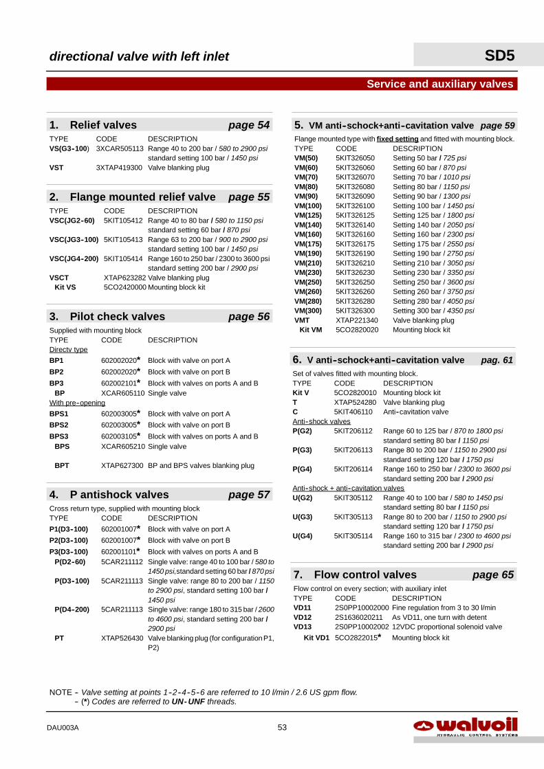
53DAU003A
3. Pilot check valves page 56Supplied with mounting blockTYPE CODE DESCRIPTIONDirectv type
BP1 602002020* Block with valve on port A
BP2 602002020* Block with valve on port B
BP3 602002101* Block with valves on ports A and BBP XCAR605110 Single valve
With pre--opening
BPS1 602003005* Block with valve on port A
BPS2 602003005* Block with valve on port B
BPS3 602003105* Block with valves on ports A and BBPS XCAR605210 Single valve
BPT XTAP627300 BP and BPS valves blanking plug
5. VM anti--schock+anti--cavitation valve page 59Flange mounted type with fixed setting and fitted with mounting block.TYPE CODE DESCRIPTIONVM(50) 5KIT326050 Setting 50 bar / 725 psiVM(60) 5KIT326060 Setting 60 bar / 870 psiVM(70) 5KIT326070 Setting 70 bar / 1010 psiVM(80) 5KIT326080 Setting 80 bar / 1150 psiVM(90) 5KIT326090 Setting 90 bar / 1300 psiVM(100) 5KIT326100 Setting 100 bar / 1450 psiVM(125) 5KIT326125 Setting 125 bar / 1800 psiVM(140) 5KIT326140 Setting 140 bar / 2050 psiVM(160) 5KIT326160 Setting 160 bar / 2300 psiVM(175) 5KIT326175 Setting 175 bar / 2550 psiVM(190) 5KIT326190 Setting 190 bar / 2750 psiVM(210) 5KIT326210 Setting 210 bar / 3050 psiVM(230) 5KIT326230 Setting 230 bar / 3350 psiVM(250) 5KIT326250 Setting 250 bar / 3600 psiVM(260) 5KIT326260 Setting 260 bar / 3750 psiVM(280) 5KIT326280 Setting 280 bar / 4050 psiVM(300) 5KIT326300 Setting 300 bar / 4350 psiVMT XTAP221340 Valve blanking plug
Kit VM 5CO2820020 Mounting block kit
Service and auxiliary valves
1. Relief valves page 54TYPE CODE DESCRIPTIONVS(G3--100) 3XCAR505113 Range 40 to 200 bar / 580 to 2900 psi
standard setting 100 bar / 1450 psiVST 3XTAP419300 Valve blanking plug
7. Flow control valves page 65Flow control on every section; with auxiliary inletTYPE CODE DESCRIPTIONVD11 2S0PP10002000 Fine regulation from 3 to 30 l/minVD12 2S1636020211 As VD11, one turn with detentVD13 2S0PP10002002 12VDC proportional solenoid valve
Kit VD1 5CO2822015* Mounting block kit
2. Flange mounted relief valve page 55TYPE CODE DESCRIPTIONVSC(JG2--60) 5KIT105412 Range 40 to 80 bar / 580 to 1150 psi
standard setting 60 bar / 870 psiVSC(JG3--100) 5KIT105413 Range 63 to 200 bar / 900 to 2900 psi
standard setting 100 bar / 1450 psiVSC(JG4--200) 5KIT105414 Range 160 to 250 bar / 2300 to 3600 psi
standard setting 200 bar / 2900 psiVSCT XTAP623282 Valve blanking plug
Kit VS 5CO2420000 Mounting block kit
NOTE -- Valve setting at points 1--2--4--5--6 are referred to 10 l/min / 2.6 US gpm flow.NOTE -- (*) Codes are referred to UN- UNF threads.
Set of valves fitted with mounting block.TYPE CODE DESCRIPTIONKit V 5CO2820010 Mounting block kitT XTAP524280 Valve blanking plugC 5KIT406110 Anti--cavitation valveAnti--shock valvesP(G2) 5KIT206112 Range 60 to 125 bar / 870 to 1800 psi
standard setting 80 bar / 1150 psiP(G3) 5KIT206113 Range 80 to 200 bar / 1150 to 2900 psi
standard setting 120 bar / 1750 psiP(G4) 5KIT206114 Range 160 to 250 bar / 2300 to 3600 psi
standard setting 200 bar / 2900 psiAnti--shock + anti--cavitation valvesU(G2) 5KIT305112 Range 40 to 100 bar / 580 to 1450 psi
standard setting 80 bar / 1150 psiU(G3) 5KIT305113 Range 80 to 200 bar / 1150 to 2900 psi
standard setting 120 bar / 1750 psiU(G4) 5KIT305114 Range 160 to 315 bar / 2300 to 4600 psi
standard setting 200 bar / 2900 psi
6. V anti--schock+anti--cavitation valve pag. 61
4. P antishock valves page 57Cross return type, supplied with mounting blockTYPE CODE DESCRIPTION
P1(D3--100) 602001007* Block with valve on port A
P2(D3--100) 602001007* Block with valve on port B
P3(D3--100) 602001101* Block with valves on ports A and BP(D2--60) 5CAR211112 Single valve: range 40 to 100 bar / 580 to
1450 psi,standard setting 60 bar / 870 psiP(D3--100) 5CAR211113 Single valve: range 80 to 200 bar / 1150
to 2900 psi, standard setting 100 bar /1450 psi
P(D4--200) 5CAR211113 Single valve: range 180 to 315 bar / 2600to 4600 psi, standard setting 200 bar /2900 psi
PT XTAP526430 Valve blanking plug (for configuration P1,P2)
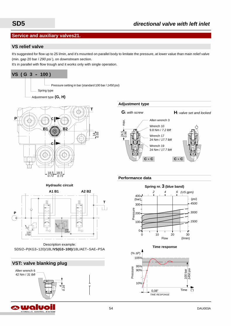
Spring nr. 3 (blue band)
0
100
200
300
400
0 10 20 30Flow
Pre
ssur
e
(l/min)
(bar) (psi)4500
3000
1500
2 4 6 (US gpm)
40.
16
VST: valve blanking plugAllen wrench 642 Nm / 31 lbft
P
A1 B1 A2 B2
T
1201001450
1750
Hydraulic circuit
Description example:SD5/2--P(KG3--120)/18L/VS(G3--100)/18L/AET--SAE--PSA
0,08”TIME RESPONSE
10%
100
bar90%
95%
105%
Pre
ssur
e
Time (”)
(% ∆P)
Time response
1450
psi
14
18.5 18.5
B1 B2
T
P
C
C
0.73 0.73
0.55
C -- C
24.5
max
.
G: with screw H: valve set and locked
C -- C
Adjustment type
Wrench 109.8 Nm / 7.2 lbft
Wrench 1724 Nm / 17.7 lbft
Wrench 1924 Nm / 17.7 lbft
Allen wrench 3
0.96
Adjustment type (G, H)
VS ( G 3 -- 100 )
Pressure setting in bar (standard 100 bar / 1450 psi)
Spring type
It’s suggested for flow up to 25 l/min, and it’s mounted on parallel body to limitate the pressure, at lower value than main relief valve
(min. gap 20 bar / 290 psi ), on downstream section.
It’s in parallel with flow trough and it works only with single operation.
VS relief valve
Service and auxiliary valves21.
Performance data
SD5 directional valve with left inlet
54 DAU003A
13
32
max
.106
24.5
3454
.5
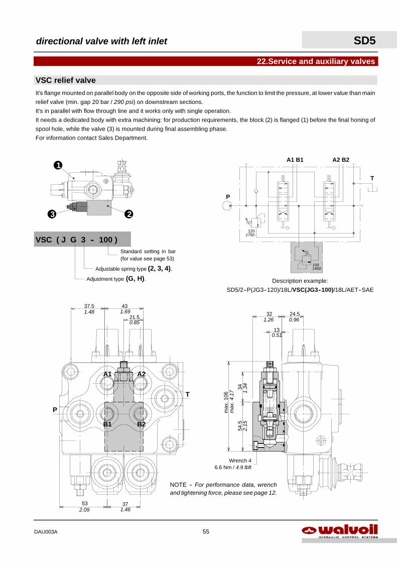
Wrench 46.6 Nm / 4.9 lbft
2.15
1.34
max
.4.1
7
0.51
1.26 0.96
A1 A2
B1 B2
P
T
21.5
4337.5
53 37
1.48 1.69
0.85
2.09 1.46
P
A1 B1 A2 B2
T
1201750
1001450
Description example:
SD5/2--P(JG3--120)/18L/VSC(JG3--100)/18L/AET--SAE
1
23
VSC relief valve
22.Service and auxiliary valves
VSC ( J G 3 -- 100 )
Adjustment type (G, H).Adjustable spring type (2, 3, 4).
Standard setting in bar(for value see page 53)
It’s flange mounted on parallel body on the opposite side of working ports, the function to limit the pressure, at lower value than main
relief valve (min. gap 20 bar / 290 psi) on downstream sections.
It’s in parallel with flow through line and it works only with single operation.
It needs a dedicated body with extra machining: for production requirements, the block (2) is flanged (1) before the final honing of
spool hole, while the valve (3) is mounted during final assembling phase.
For information contact Sales Department.
NOTE -- For performance data, wrenchand tightening force, please see page 12.
directional valve with left inlet SD5
55DAU003A
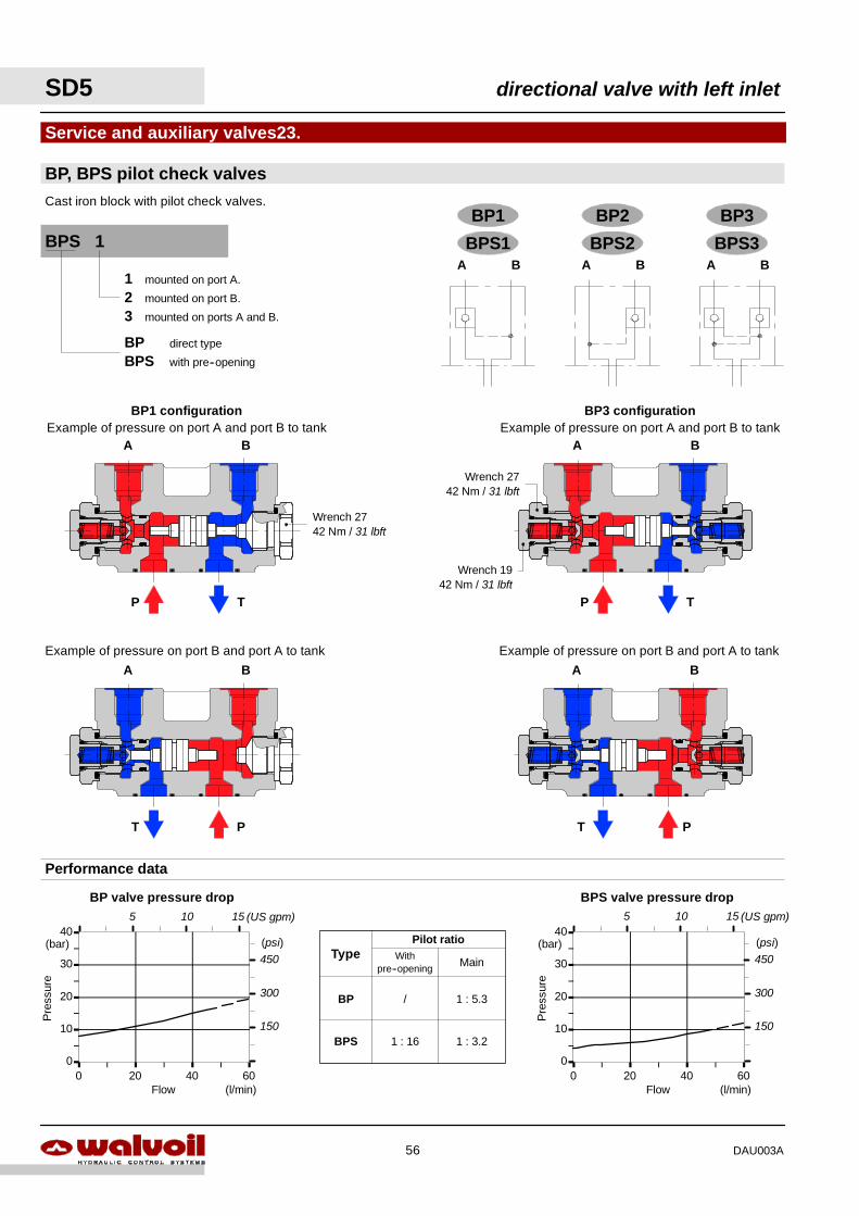
BA
PT
A B
P T
A B
PT
A B
P T
0
10
20
30
40
0 20 40 60
BPS valve pressure drop
Flow
Pre
ssur
e
(l/min)
(bar) (psi)450
300
150
5 10 15 (US gpm)
BP valve pressure drop
0
10
20
30
40
0 20 40 60Flow
Pre
ssur
e
(l/min)
(bar) (psi)450
300
150
5 10 15 (US gpm)
Performance data
TypePilot ratio
Withpre--opening Main
BP
BPS 1 : 16
1 : 5.3
1 : 3.2
/
BP direct type
BPS with pre--opening
1 mounted on port A.
2 mounted on port B.
3 mounted on ports A and B.
BPS 1
BP3 configurationExample of pressure on port A and port B to tank
BP1 configurationExample of pressure on port A and port B to tank
Example of pressure on port B and port A to tankExample of pressure on port B and port A to tank
Wrench 1942 Nm / 31 lbft
Wrench 2742 Nm / 31 lbft
Wrench 2742 Nm / 31 lbft
BP, BPS pilot check valves
Service and auxiliary valves23.
BP1 BP2 BP3
A B
Cast iron block with pilot check valves.
A B A B
BPS1 BPS2 BPS3
SD5 directional valve with left inlet
56 DAU003A
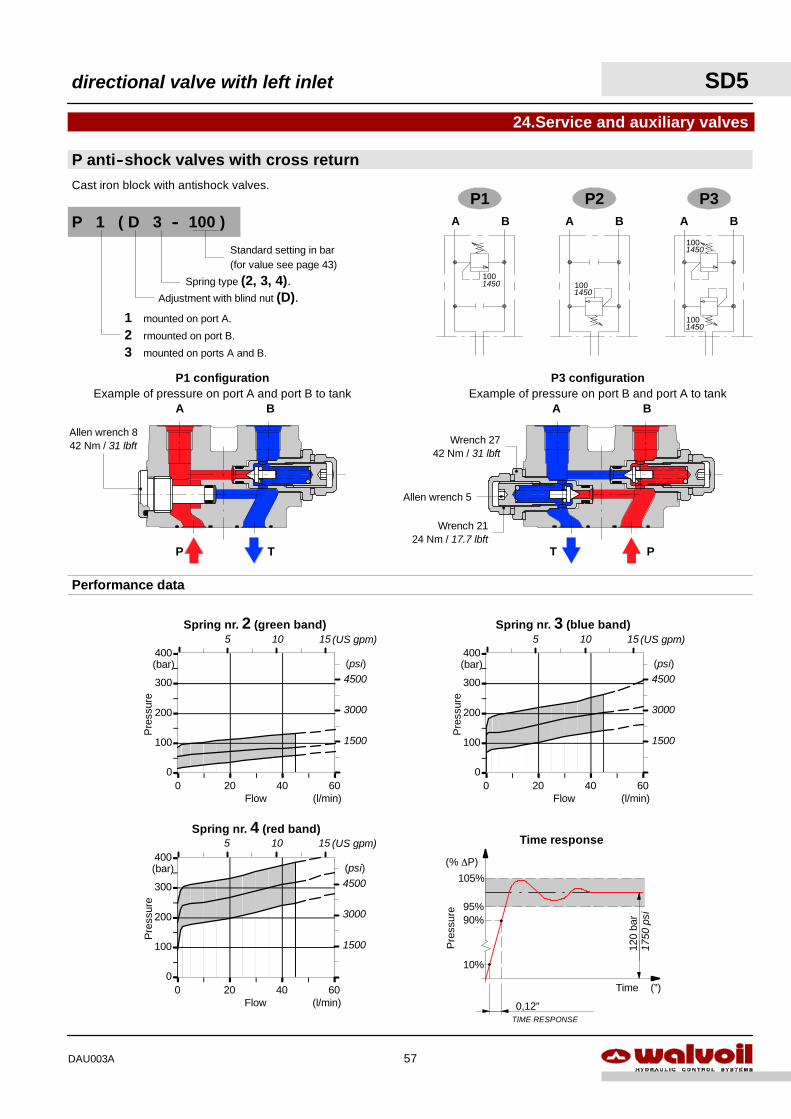
A B
PT
A B
P T
0,12”TIME RESPONSE
10%
120
bar90%
95%
105%
Pre
ssur
e
Time (”)
(% ∆P)
Time response
1750
psi
Spring nr. 4 (red band)
0
100
200
300
400
0 20 40 60Flow
Pre
ssur
e
(l/min)
(bar) (psi)4500
3000
1500
Spring nr. 3 (blue band)
0
100
200
300
400
0 20 40 60Flow
Pre
ssur
e
(l/min)
(bar) (psi)4500
3000
1500
Spring nr. 2 (green band)
0
100
200
300
400
0 20 40 60Flow
Pre
ssur
e
(l/min)
(bar) (psi)4500
3000
1500
5 10 15 (US gpm)
5 10 15 (US gpm) 5 10 15 (US gpm)
Performance data
P1 P2 P3A B A B A B
1001450 100
1450
1001450
1001450
P anti--shock valves with cross return
24.Service and auxiliary valves
Cast iron block with antishock valves.
P3 configurationExample of pressure on port B and port A to tank
P1 configurationExample of pressure on port A and port B to tank
Wrench 2124 Nm / 17.7 lbft
Allen wrench 5
Wrench 2742 Nm / 31 lbft
Allen wrench 842 Nm / 31 lbft
Adjustment with blind nut (D).Spring type (2, 3, 4).
P 1 ( D 3 -- 100 )
1 mounted on port A.
2 rmounted on port B.
3 mounted on ports A and B.
Standard setting in bar(for value see page 43)
directional valve with left inlet SD5
57DAU003A
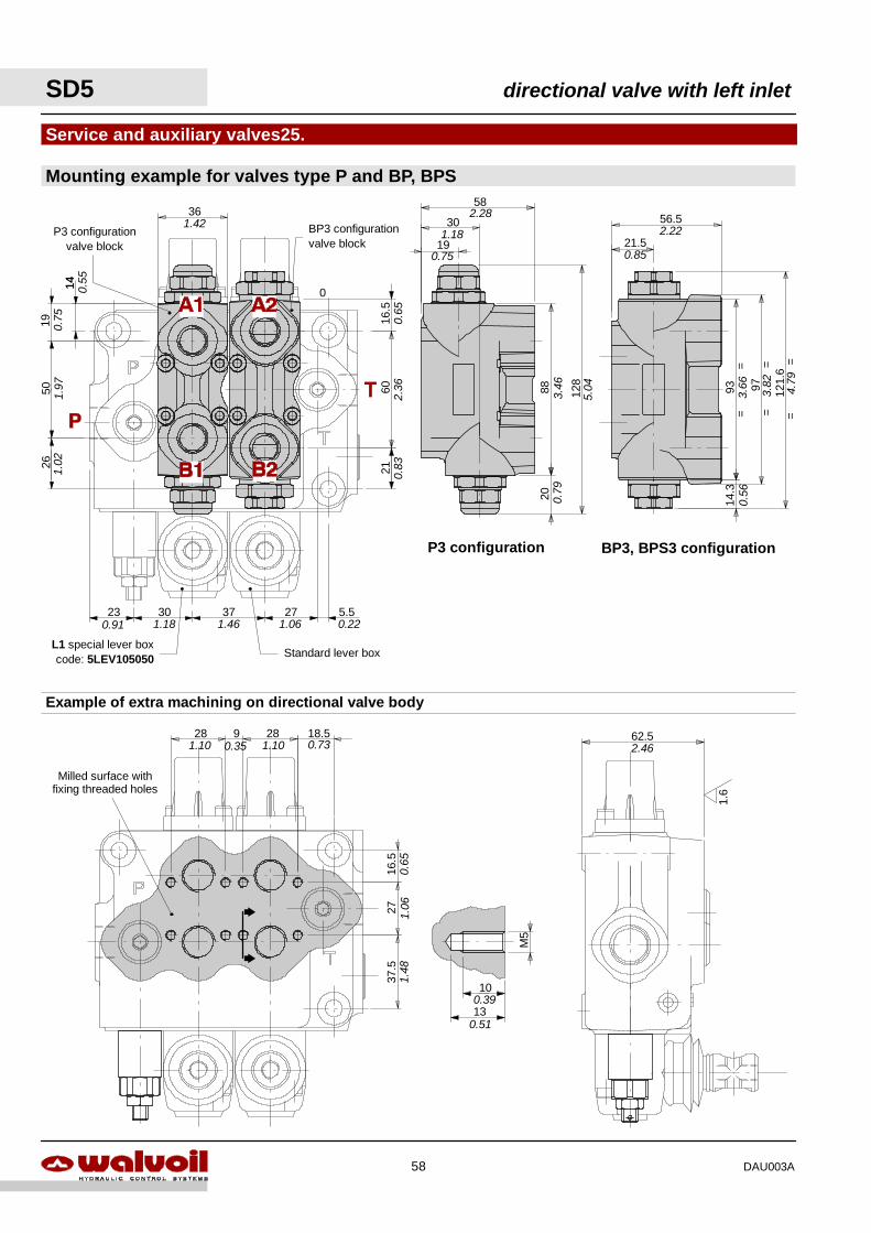
0
62.52.46
1.6
M5
10
130.39
0.51
16.5
0.65
2828 9 18.51.10 0.35 1.10 0.73
Milled surface withfixing threaded holes
2737
.51.
061.
48
Example of extra machining on directional valve body
361.42
16.5
21
14
5019
60
26
37 273023 5.50.91 1.18 1.46 1.06 0.22
0.65
2.36
0.83
0.75
14 0.55
1.97
1.02
L1 special lever boxcode: 5LEV105050 Standard lever box
BP3 configurationvalve block
P3 configurationvalve block
P3 configuration BP3, BPS3 configuration
21.5
56.5
121.
6=
=
93=
=97
==
14.3
2.22
0.85
0.56
3.66
3.82
4.79
2088 12
8
19
30
58
0.75
1.18
2.28
3.46
0.79
5.04
Mounting example for valves type P and BP, BPS
Service and auxiliary valves25.
SD5 directional valve with left inlet
58 DAU003A
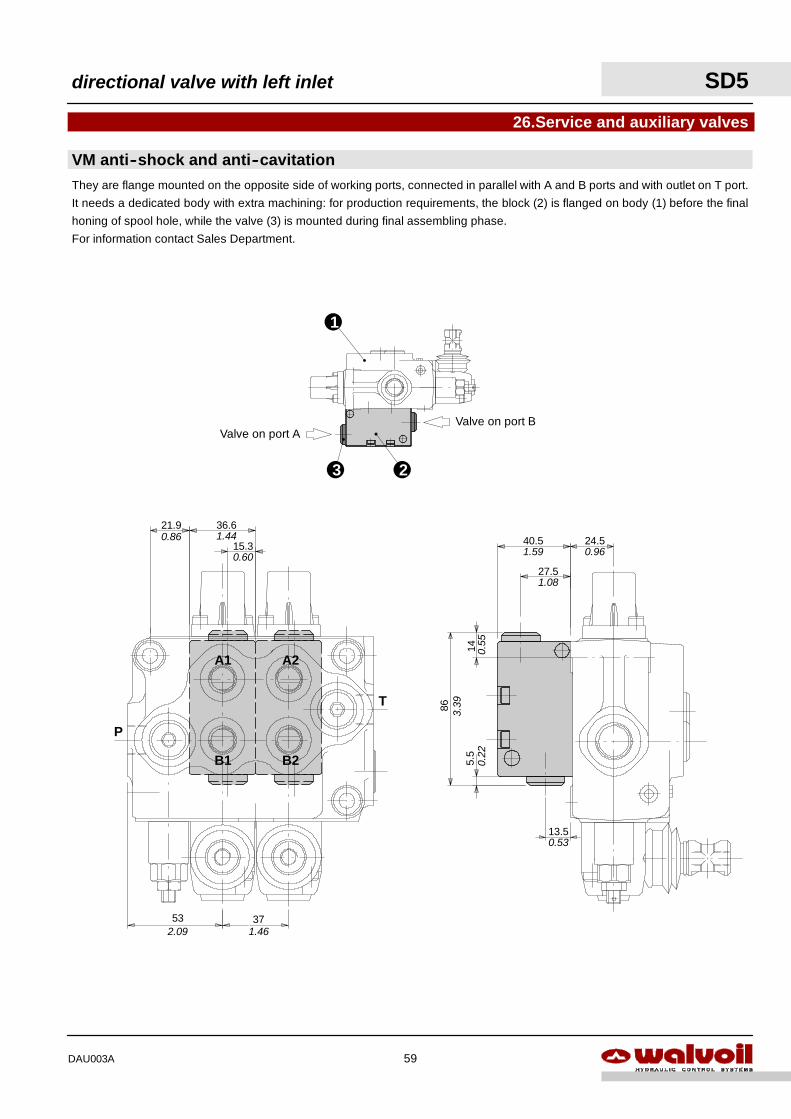
27.5
40.5
14
86
13.5
24.5
5.5
3.39
0.55
0.22
0.53
1.08
1.59 0.96
A1 A2
B1 B2
P
T
15.3
36.621.9
53 37
0.86 1.44
0.60
2.09 1.46
1
23
26.Service and auxiliary valves
Valve on port BValve on port A
VM anti--shock and anti--cavitationThey are flange mounted on the opposite side of working ports, connected in parallel with A and B ports and with outlet on T port.
It needs a dedicated body with extra machining: for production requirements, the block (2) is flanged on body (1) before the final
honing of spool hole, while the valve (3) is mounted during final assembling phase.
For information contact Sales Department.
directional valve with left inlet SD5
59DAU003A
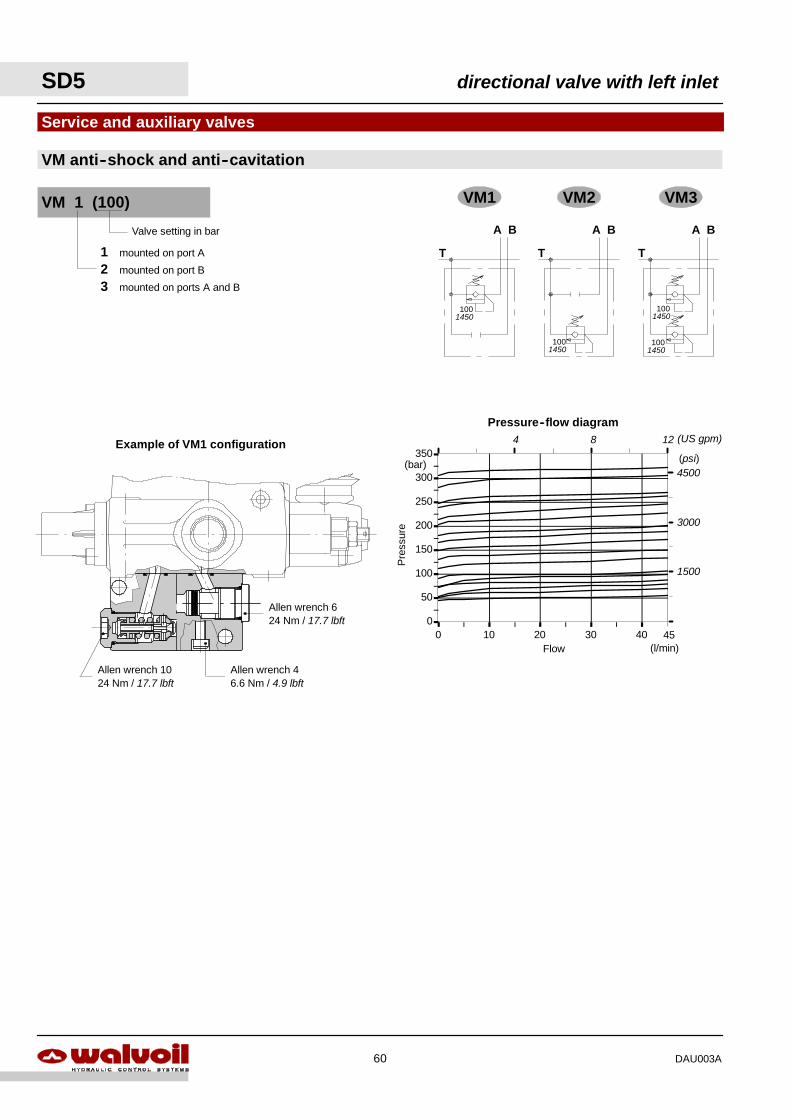
0
50
100
150
200
250
300
350
0 10 20 30 40
Pressure--flow diagram
Flow
Pre
ssur
e
(bar)
(l/min)45
(psi)4500
3000
1500
4 8 (US gpm)12
Allen wrench 624 Nm / 17.7 lbft
Allen wrench 46.6 Nm / 4.9 lbft
Allen wrench 1024 Nm / 17.7 lbft
VM1 VM2 VM3
A B
T
A BA B
TT
1001450
1001450
1001450
1001450
Valve setting in bar
1 mounted on port A
2 mounted on port B
3 mounted on ports A and B
VM 1 (100)
VM anti--shock and anti--cavitation
Service and auxiliary valves
Example of VM1 configuration
SD5 directional valve with left inlet
60 DAU003A
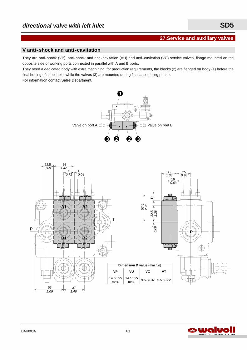
P
57.5
32.5
2
2535
16
D
1.38 0.98
0.63
1.28
2.26
0.08
5.5 / 0.22
Dimension D value (mm / in)
VP VCVU VT
9.5 / 0.3714 / 0.55max.
14 / 0.55max.
A1 A2
B1 B2
P
T
18
3622.5
53 37
10.89 1.42
0.71 0.04
2.09 1.46
1
2
27.Service and auxiliary valves
323
Valve on port BValve on port A
They are anti--shock (VP), anti--shock and anti--cavitation (VU) and anti--cavitation (VC) service valves, flange mounted on the
opposite side of working ports connected in parallel with A and B ports.
They need a dedicated body with extra machining: for production requirements, the blocks (2) are flanged on body (1) before the
final honing of spool hole, while the valves (3) are mounted during final assembling phase.
For information contact Sales Department.
V anti--shock and anti--cavitation
directional valve with left inlet SD5
61DAU003A
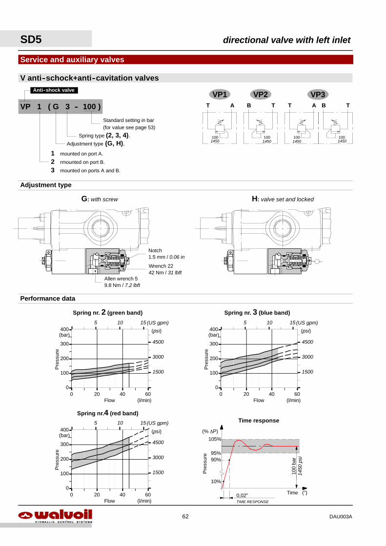
0
100
200
300
400
0 20 40 60
0
100
200
300
400
0 20 40 600
100
200
300
400
0 20 40 60
G: with screw H: valve set and locked
Adjustment type
Allen wrench 59.8 Nm / 7.2 lbft
Wrench 2242 Nm / 31 lbft
Notch1.5 mm / 0.06 in
VP1 VP2T A
100
B T
100
T A
100
B T
100
VP3
1450 1450 1450 1450
VP 1 ( G 3 -- 100 )
Adjustment type (G, H).Spring type (2, 3, 4).
1 mounted on port A.
2 rmounted on port B.
3 mounted on ports A and B.
Standard setting in bar(for value see page 53)
Anti--shock valve
V anti--schock+anti--cavitation valves
Service and auxiliary valves
0,02”TIME RESPONSE
10%
100
bar90%
95%
105%
Pre
ssur
e
Time (”)
(% ∆P)
Time response
1450
psi
Spring nr.4 (red band)
Flow
Pre
ssur
e
(l/min)
(bar)(psi)
4500
3000
1500
Spring nr. 3 (blue band)
Flow
Pre
ssur
e
(l/min)
(bar)(psi)
4500
3000
1500
Spring nr. 2 (green band)
Flow
Pre
ssur
e
(l/min)
(bar)(psi)
4500
3000
1500
Performance data
5 10 15 (US gpm) 5 10 15 (US gpm)
5 10 15 (US gpm)
SD5 directional valve with left inlet
62 DAU003A
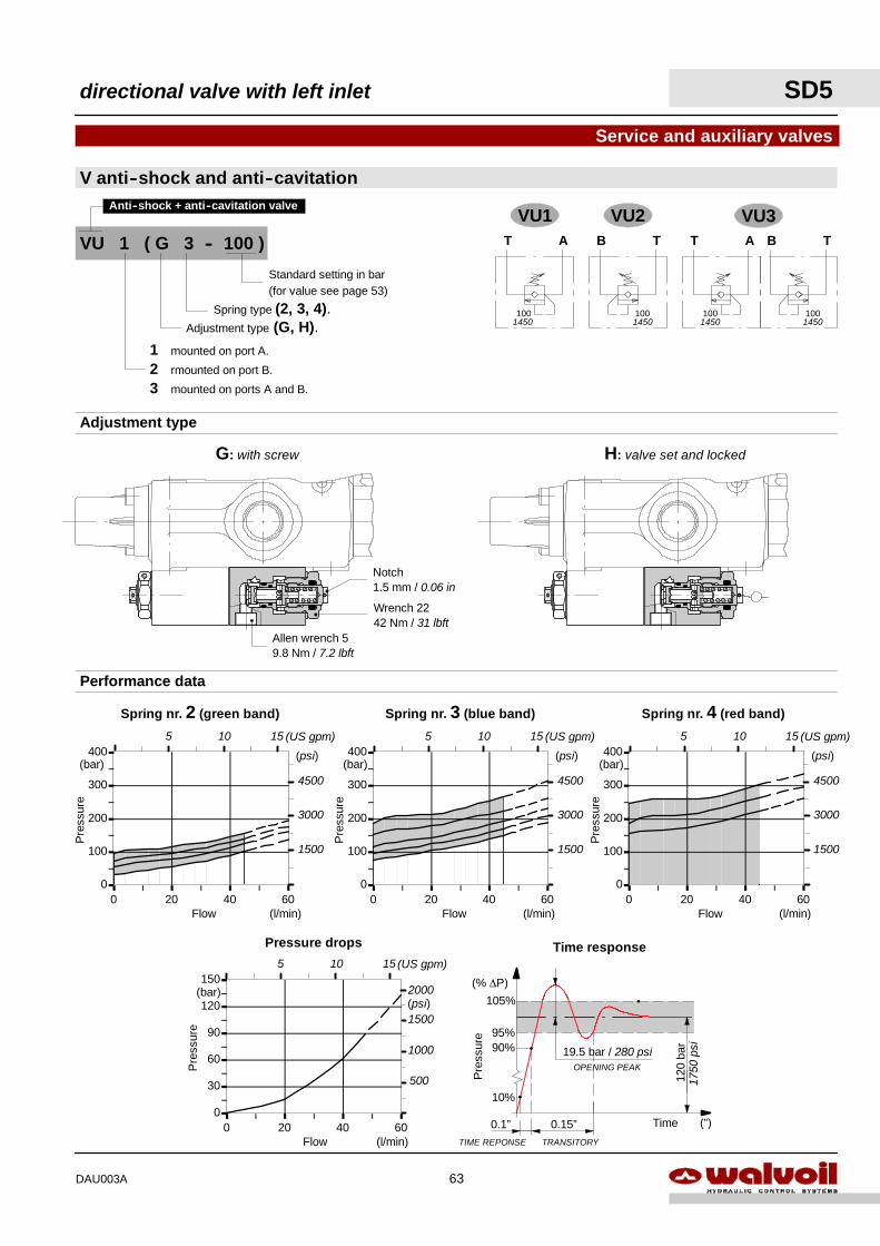
VU1 VU2T A
100
B T
100
T A
100
B T
100
VU3
1450 145014501450
VU 1 ( G 3 -- 100 )
Adjustment type (G, H).Spring type (2, 3, 4).
1 mounted on port A.
2 rmounted on port B.
3 mounted on ports A and B.
Standard setting in bar(for value see page 53)
Anti--shock + anti--cavitation valve
Pressure drops
0
30
60
90
120
150
0 20 40 60Flow
Pre
ssur
e
(l/min)
(bar)
V anti--shock and anti--cavitation
Service and auxiliary valves
0
100
200
300
400
0 20 40 60
Performance data
0
100
200
300
400
0 20 40 600
100
200
300
400
0 20 40 60Flow
Pre
ssur
e
(l/min)
(bar)
Flow
Pre
ssur
e
(l/min)
(bar)
Spring nr. 3 (blue band) Spring nr. 4 (red band)
Flow
Pre
ssur
e
(l/min)
(bar)
Spring nr. 2 (green band)
0.1”TIME REPONSE
10%
120
bar90%
95%
105%
Pre
ssur
e
Time (”)
(% ∆P)
0.15”TRANSITORY
19.5 bar / 280 psiOPENING PEAK
Time response
G: with screw H: valve set and locked
Adjustment type
Allen wrench 59.8 Nm / 7.2 lbft
Wrench 2242 Nm / 31 lbft
Notch1.5 mm / 0.06 in
(psi)
4500
3000
1500
(psi)
4500
3000
1500
(psi)
4500
3000
1500
1500
1000
500
(psi)2000
1750
psi
5 10 15 (US gpm) 5 10 15 (US gpm) 5 10 15 (US gpm)
5 10 15 (US gpm)
directional valve with left inlet SD5
63DAU003A
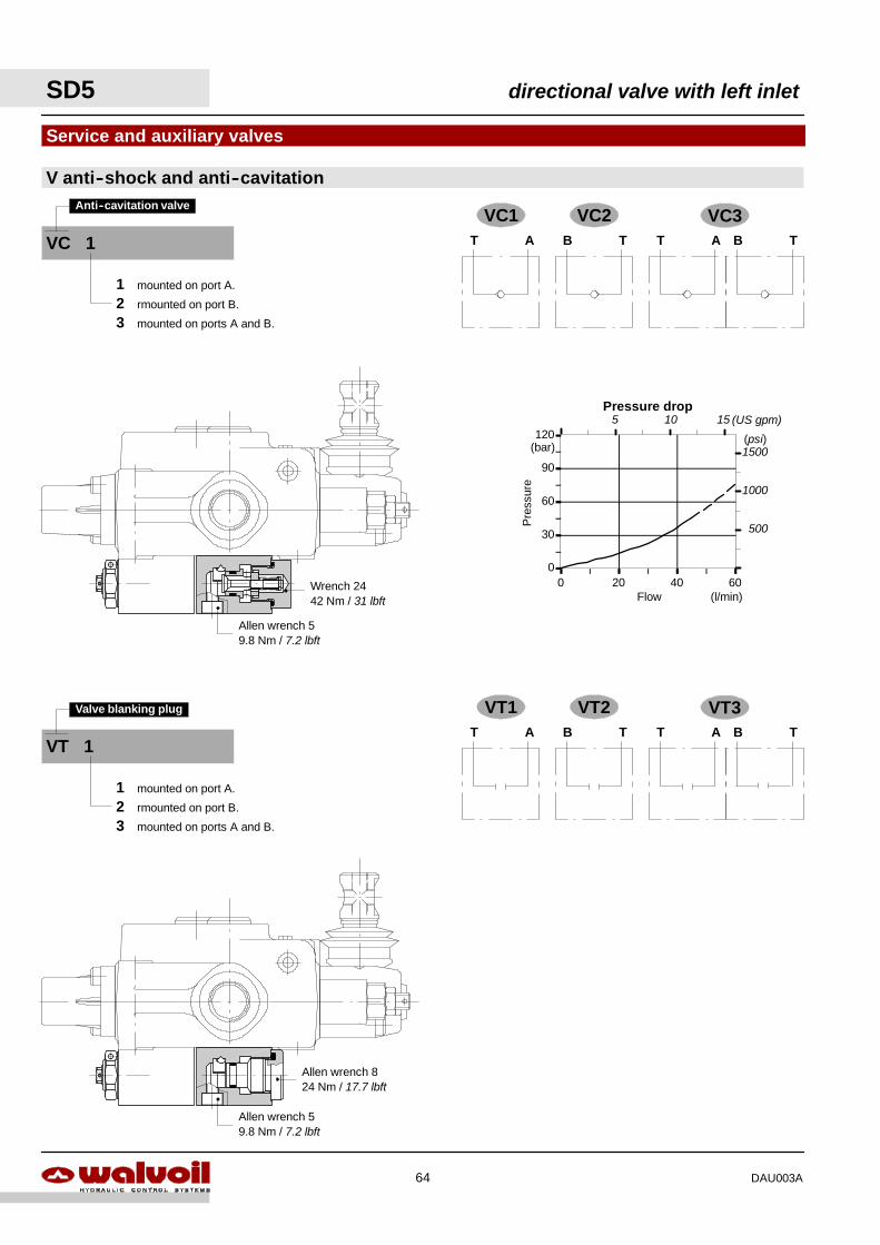
Allen wrench 824 Nm / 17.7 lbft
Allen wrench 59.8 Nm / 7.2 lbft
Wrench 2442 Nm / 31 lbft
Allen wrench 59.8 Nm / 7.2 lbft
Pressure drop
0
30
60
90
120
0 20 40 60Flow
Pre
ssur
e
(l/min)
(bar)
V anti--shock and anti--cavitation
Service and auxiliary valves
VC1 VC2T A B T T A B T
VC3
VT1 VT2T A B T T A B T
VT3
VC 1
Anti--cavitation valve
1 mounted on port A.
2 rmounted on port B.
3 mounted on ports A and B.
VT 1
Valve blanking plug
1 mounted on port A.
2 rmounted on port B.
3 mounted on ports A and B.
1500
1000
500
(psi)
5 10 15 (US gpm)
SD5 directional valve with left inlet
64 DAU003A
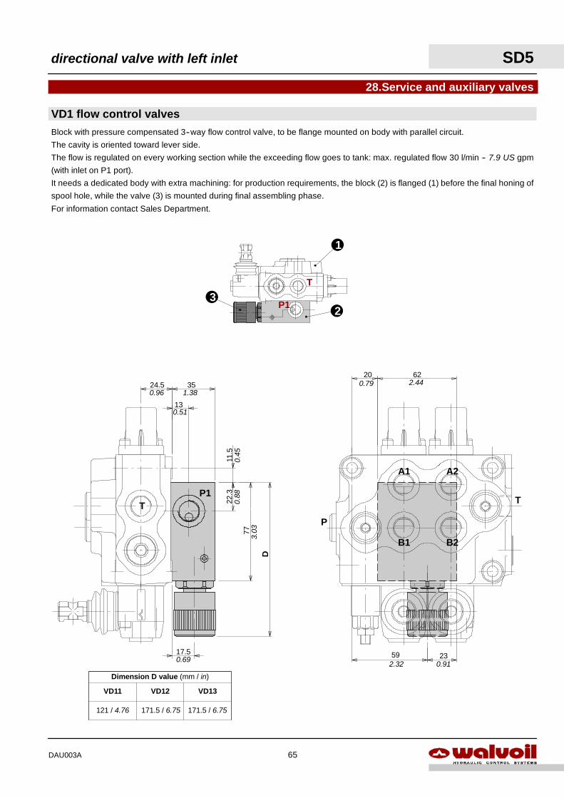
A1 A2
B1 B2
P
T
6220
59 232.32 0.91
0.79 2.44
17.5
35
D
24.5
11.5
77
13
22.3
TP1
0.96 1.38
0.51
0.45
0.88
3.03
0.69
T
P1
1
23
28.Service and auxiliary valves
Block with pressure compensated 3--way flow control valve, to be flange mounted on body with parallel circuit.
The cavity is oriented toward lever side.
The flow is regulated on every working section while the exceeding flow goes to tank: max. regulated flow 30 l/min -- 7.9 US gpm
(with inlet on P1 port).
It needs a dedicated body with extra machining: for production requirements, the block (2) is flanged (1) before the final honing of
spool hole, while the valve (3) is mounted during final assembling phase.
For information contact Sales Department.
VD1 flow control valves
Dimension D value (mm / in)
VD11 VD13VD12
171.5 / 6.75171.5 / 6.75121 / 4.76
directional valve with left inlet SD5
65DAU003A
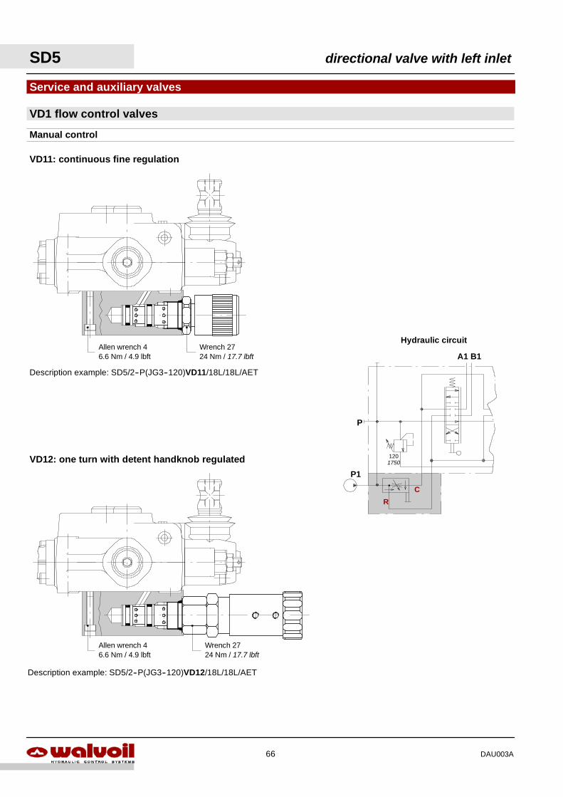
Description example: SD5/2--P(JG3--120)VD12/18L/18L/AET
Allen wrench 46.6 Nm / 4.9 lbft
Wrench 2724 Nm / 17.7 lbft
P
A1 B1
120
P1
Hydraulic circuit
C
R
1750
Description example: SD5/2--P(JG3--120)VD11/18L/18L/AET
Allen wrench 46.6 Nm / 4.9 lbft
Wrench 2724 Nm / 17.7 lbft
VD1 flow control valves
Service and auxiliary valves
VD12: one turn with detent handknob regulated
Manual control
VD11: continuous fine regulation
SD5 directional valve with left inlet
66 DAU003A
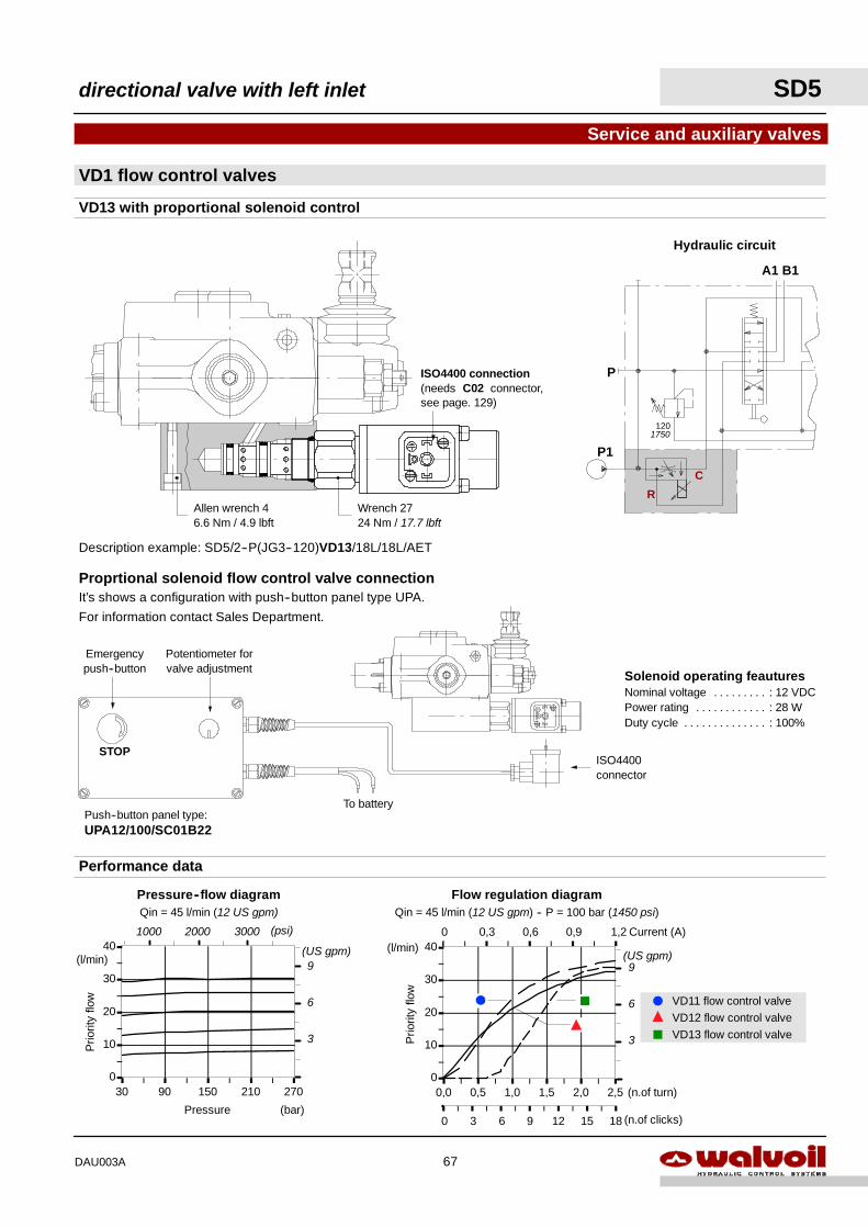
0,3 0,6 0,9 1,2 Current (A)0
0
10
20
30
40
0,0 0,5 1,0 1,5 2,0 2,5
3 6 9 12 15 18
Flow regulation diagramQin = 45 l/min (12 US gpm) -- P = 100 bar (1450 psi)
Prio
rity
flow
(l/min)
(n.of clicks)
(n.of turn)
0
F J
Y
(US gpm)
3
6
9
0
10
20
30
40
30 90 150 210 270
Prio
rity
flow
(l/min)
Pressure (bar)
Pressure--flow diagramQin = 45 l/min (12 US gpm)
(psi)1000 2000 3000
(US gpm)
3
6
9
Performance data
F
J
Y
VD11 flow control valveVD12 flow control valveVD13 flow control valve
Solenoid operating feauturesNominal voltage : 12 VDC. . . . . . . . .Power rating : 28 W. . . . . . . . . . . .Duty cycle : 100%. . . . . . . . . . . . . .
To battery
Potentiometer forvalve adjustment
Emergencypush--button
Push--button panel type:UPA12/100/SC01B22
ISO4400connector
STOP
P
A1 B1
P1
C
R
1201750
Hydraulic circuit
Proprtional solenoid flow control valve connectionIt’s shows a configuration with push--button panel type UPA.
For information contact Sales Department.
Allen wrench 46.6 Nm / 4.9 lbft
Wrench 2724 Nm / 17.7 lbft
VD1 flow control valves
Service and auxiliary valves
VD13 with proportional solenoid control
Description example: SD5/2--P(JG3--120)VD13/18L/18L/AET
ISO4400 connection(needs C02 connector,see page. 129)
directional valve with left inlet SD5
67DAU003A
SD5 directional valve with left inlet
68 DAU003A
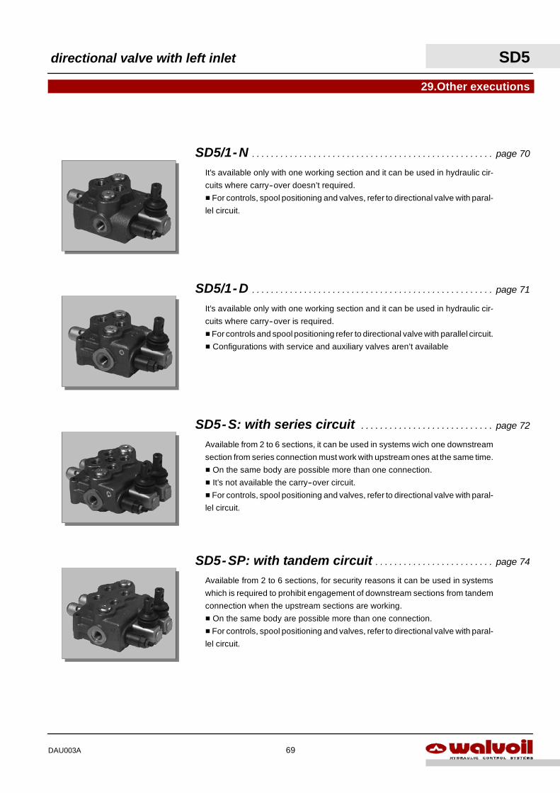
Available from 2 to 6 sections, it can be used in systems wich one downstream
section from series connection must work with upstream ones at the same time.
H On the same body are possible more than one connection.
H It’s not available the carry--over circuit.
H For controls, spool positioning and valves, refer to directional valve with paral-
lel circuit.
29.Other executions
It’s available only with one working section and it can be used in hydraulic cir-
cuits where carry--over is required.
HFor controls and spool positioning refer to directional valve with parallel circuit.
H Configurations with service and auxiliary valves aren’t available
It’s available only with one working section and it can be used in hydraulic cir-
cuits where carry--over doesn’t required.
H For controls, spool positioning and valves, refer to directional valve with paral-
lel circuit.
SD5-SP: with tandem circuit page 74. . . . . . . . . . . . . . . . . . . . . . . . .
Available from 2 to 6 sections, for security reasons it can be used in systems
which is required to prohibit engagement of downstream sections from tandem
connection when the upstream sections are working.
H On the same body are possible more than one connection.
H For controls, spool positioning and valves, refer to directional valve with paral-
lel circuit.
SD5-S: with series circuit page 72. . . . . . . . . . . . . . . . . . . . . . . . . . . .
SD5/1-D page 71. . . . . . . . . . . . . . . . . . . . . . . . . . . . . . . . . . . . . . . . . . . . . . . . . . .
SD5/1-N page 70. . . . . . . . . . . . . . . . . . . . . . . . . . . . . . . . . . . . . . . . . . . . . . . . . . .
directional valve with left inlet SD5
69DAU003A
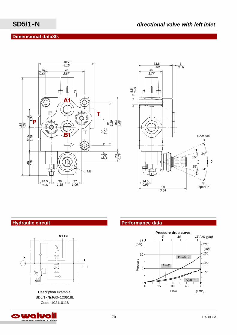
0
5
10
15
0 15 30 45 60
Flow
Pre
ssur
e
(l/min)
(bar)
P→T
P→A(B)
A(B)→T
Pressure drop curve
(psi)150
100
50
200
5 10 15 (US gpm)
P
A1 B1
T
1201750
Description example:
SD5/1--N(JG3--120)/18L
Code: 102110118
15°
15°
1
2
0
24°
24°
spool out3
3spool in
63.5 5
45
8.5
24.5
90
0.33
1.77
2.50 0.20
0.96
3.54
51
81
11.5
103
20
273024.5
4645
.534
186
14 73
105.5
M8
4.15
0.55 2.87
7.32
1.34
1.79
1.81
0.96 1.18 1.06
0.79
0.45
2.01
3.19
4.06
Dimensional data30.
Hydraulic circuit Performance data
SD5/1--N directional valve with left inlet
70 DAU003A
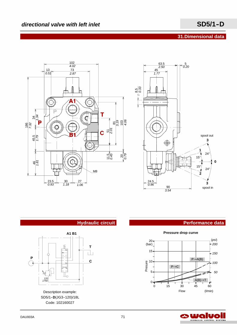
P
A1 B1
120
T
C
1750
Description example:
SD5/1--D(JG3--120)/18L
Code: 102160027
0
5
10
15
20
0 15 30 45 60
Flow
Pre
sure
(l/min)
(bar)
P→C
P→A(B)
A(B)→T
Pressure drop curve
(psi)
150
100
50
200
51
81
11.5
103
20
273023.5
4645
.534
186
13 73
102
M8
4.02
2.870.51
7.32
1.34
1.79
1.81
0.93 1.18 1.06
0.45
0.79
4.06
3.19
2.01
31.Dimensional data
Hydraulic circuit Performance data
15°
15°
1
2
0
24°
24°
spool out3
3spool in
63.5 5
45
8.5
24.5
90
0.33
1.77
2.50 0.20
0.96
3.54
directional valve with left inlet SD5/1--D
71DAU003A
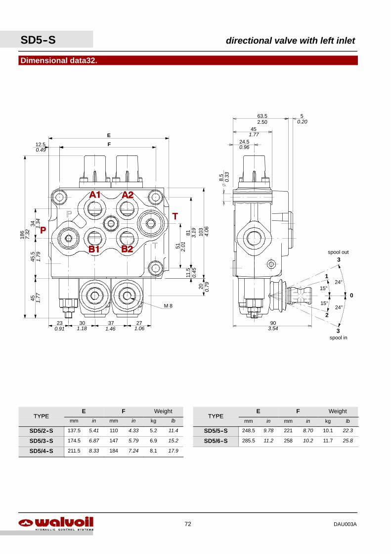
30 37
51
81
34
186 103
45
12.5
11.5
23
45.5
27
M 8
20
F
E
0.49
7.32
1.34
1.79
1.77
0.91 1.18 1.46 1.06
0.79
0.45
2.01
3.19 4.06
Dimensional data32.
15°
15°
1
2
0
24°
24°
spool out3
3spool in
63.5 5
45
24.5
90
8.5
0.33
0.96
1.77
2.50 0.20
3.54
SD5--S directional valve with left inlet
72 DAU003A
TYPEE F Weight
TYPEE F Weight
TYPEmm in mm in kg lb
TYPEmm in mm in kg lb
SD5/2--S 137.5 5.41 110 4.33 5.2 11.4 SD5/5--S 248.5 9.78 221 8.70 10.1 22.3
SD5/3--S 174.5 6.87 147 5.79 6.9 15.2 SD5/6--S 285.5 11.2 258 10.2 11.7 25.8
SD5/4--S 211.5 8.33 184 7.24 8.1 17.9
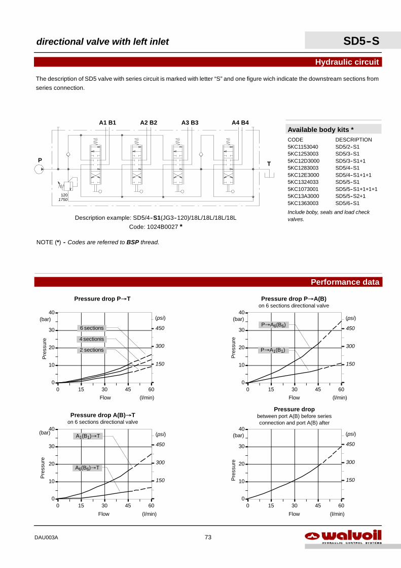
0
10
20
30
40
0 15 30 45 60
Flow
Pre
ssur
e
(l/min)
(bar)
Pressure dropbetween port A(B) before seriesconnection and port A(B) after
(psi)
450
300
150
0
10
20
30
40
0 15 30 45 60
A6(B6)→T
A1(B1)→T
Flow
Pre
ssur
e
(l/min)
(bar)
Pressure drop A(B)→Ton 6 sections directional valve
(psi)
450
300
150
0
10
20
30
40
0 15 30 45 60
P→A6(B6)
Flow
Pre
ssur
e
(l/min)
(bar)
Pressure drop P→A(B)on 6 sections directional valve
P→A1(B1)
(psi)
450
300
150
0
10
20
30
40
0 15 30 45 60
Flow
Pre
ssur
e
(l/min)
(bar)
Pressure drop P→T
2 sections
4 sectionis
6 sections
(psi)
450
300
150
The description of SD5 valve with series circuit is marked with letter “S” and one figure wich indicate the downstream sections from
series connection.
Hydraulic circuit
Performance data
A3 B3 A4 B4
T
Description example: SD5/4--S1(JG3--120)/18L/18L/18L/18L
Code: 1024B0027 *
P
A1 B1 A2 B2
120
NOTE (*) -- Codes are referred to BSP thread.
1750
Available body kits *CODE DESCRIPTION5KC1153040 SD5/2--S15KC1253003 SD5/3--S15KC12D3000 SD5/3--S1+15KC1283003 SD5/4--S15KC12E3000 SD5/4--S1+1+15KC1324033 SD5/5--S15KC1073001 SD5/5--S1+1+1+15KC13A3000 SD5/5--S2+15KC1363003 SD5/6--S1
Include boby, seals and load checkvalves.
directional valve with left inlet SD5--S
73DAU003A
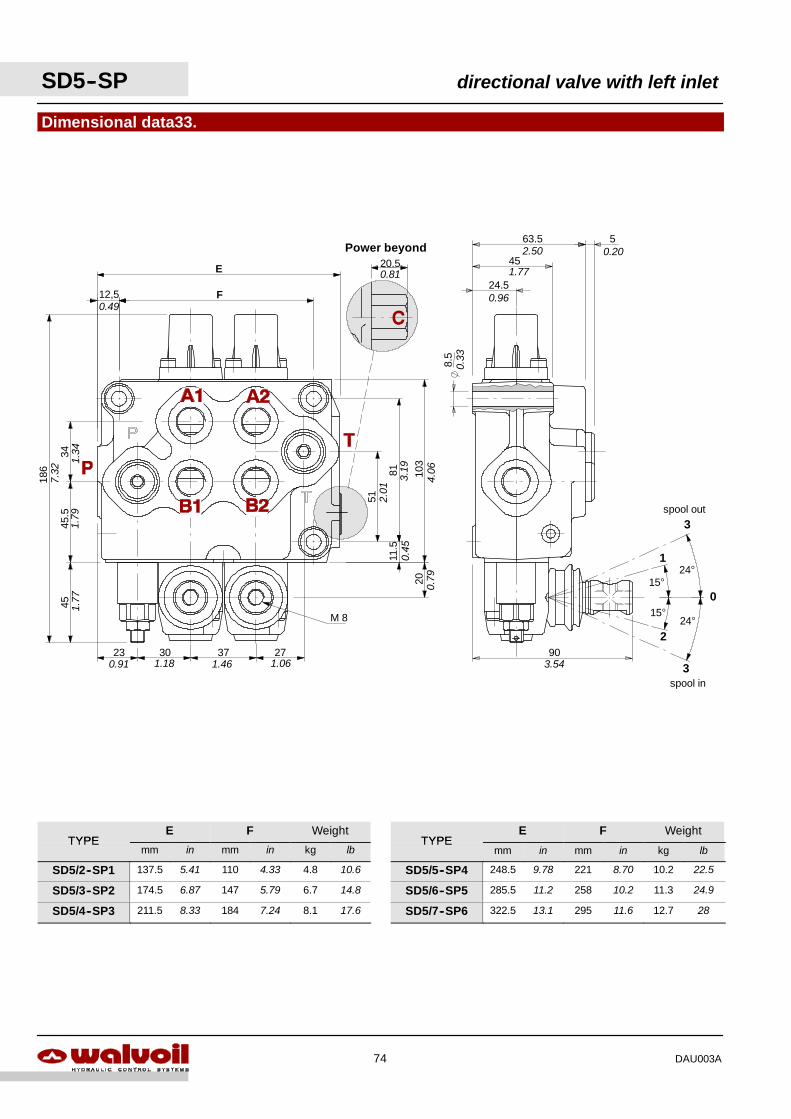
51
81
34
186 103
45
12,5
11.5
45.5
M 8
20
F
E
0.49
1.34
1.79
1.77
7.32
30 3723 270.91 1.18 1.46 1.06
0.45
2.01
3.19
4.06
0.79
Dimensional data33.
15°
15°
1
2
0
24°
24°
spool out3
3spool in
20.5Power beyond
0.81
63.5 5
45
8.5
24.5
903.54
2.50
1.77
0.20
0.96
0.33
SD5--SP directional valve with left inlet
74 DAU003A
TYPEE F Weight
TYPEE F Weight
TYPEmm in mm in kg lb
TYPEmm in mm in kg lb
SD5/2--SP1 137.5 5.41 110 4.33 4.8 10.6 SD5/5--SP4 248.5 9.78 221 8.70 10.2 22.5
SD5/3--SP2 174.5 6.87 147 5.79 6.7 14.8 SD5/6--SP5 285.5 11.2 258 10.2 11.3 24.9
SD5/4--SP3 211.5 8.33 184 7.24 8.1 17.6 SD5/7--SP6 322.5 13.1 295 11.6 12.7 28
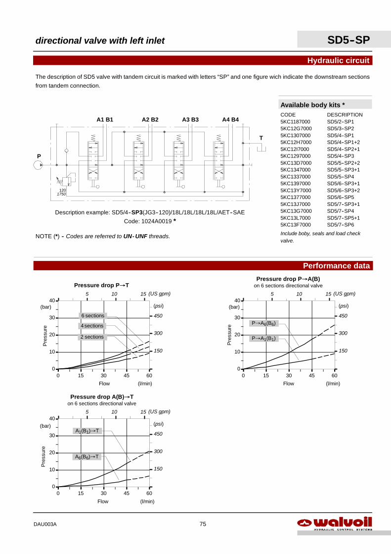
0
10
20
30
40
0 15 30 45 60
A6(B6)→T
A1(B1)→T
Flow
Pre
ssur
e
(l/min)
(bar)
Pressure drop A(B)→Ton 6 sections directional valve
(psi)
450
300
150
5 10 15 (US gpm)
0
10
20
30
40
0 15 30 45 60
P→A6(B6)
Flow
Pre
ssur
e
(l/min)
(bar)
Pressure drop P→A(B)on 6 sections directional valve
P→A1(B1)
(psi)
450
300
150
5 10 15 (US gpm)
0
10
20
30
40
0 15 30 45 60
Flow
Pre
ssur
e
(l/min)
(bar)
Pressure drop P→T
6 sections
4 sections
(psi)
450
300
150
2 sections
5 10 15 (US gpm)
The description of SD5 valve with tandem circuit is marked with letters “SP” and one figure wich indicate the downstream sections
from tandem connection.
Hydraulic circuit
Performance data
A3 B3 A4 B4
Description example: SD5/4--SP3(JG3--120)/18L/18L/18L/18L/AET--SAE
Code: 1024A0019 *
P
A1 B1 A2 B2
120
T
NOTE (*) -- Codes are referred to UN- UNF threads.
Available body kits *CODE DESCRIPTION5KC1187000 SD5/2--SP15KC12G7000 SD5/3--SP25KC1307000 SD5/4--SP15KC12H7000 SD5/4--SP1+25KC12I7000 SD5/4--SP2+15KC1297000 SD5/4--SP35KC13D7000 SD5/5--SP2+25KC1347000 SD5/5--SP3+15KC1337000 SD5/5--SP45KC1397000 SD5/6--SP3+15KC13Y7000 SD5/6--SP3+25KC1377000 SD5/6--SP55KC13J7000 SD5/7--SP3+15KC13G7000 SD5/7--SP45KC13L7000 SD5/7--SP5+15KC13F7000 SD5/7--SP6
Include boby, seals and load checkvalve.
1750
directional valve with left inlet SD5--SP
75DAU003A
SD5
76 DAU003A
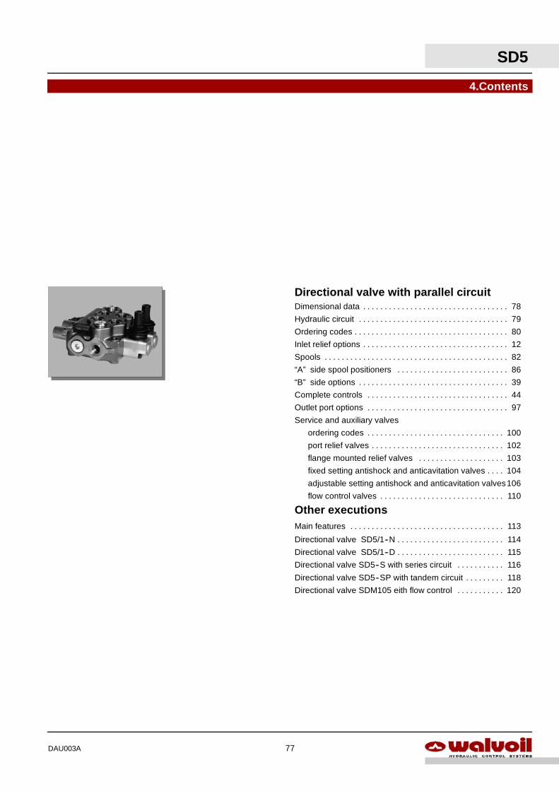
SD5
77DAU003A
4.Contents
Directional valve with parallel circuitDimensional data 78. . . . . . . . . . . . . . . . . . . . . . . . . . . . . . . . . .
Hydraulic circuit 79. . . . . . . . . . . . . . . . . . . . . . . . . . . . . . . . . . .
Ordering codes 80. . . . . . . . . . . . . . . . . . . . . . . . . . . . . . . . . . . .
Inlet relief options 12. . . . . . . . . . . . . . . . . . . . . . . . . . . . . . . . . .
Spools 82. . . . . . . . . . . . . . . . . . . . . . . . . . . . . . . . . . . . . . . . . . .
“A” side spool positioners 86. . . . . . . . . . . . . . . . . . . . . . . . . .
“B” side options 39. . . . . . . . . . . . . . . . . . . . . . . . . . . . . . . . . . .
Complete controls 44. . . . . . . . . . . . . . . . . . . . . . . . . . . . . . . . .
Outlet port options 97. . . . . . . . . . . . . . . . . . . . . . . . . . . . . . . . .
Service and auxiliary valves
ordering codes 100. . . . . . . . . . . . . . . . . . . . . . . . . . . . . . . .
port relief valves 102. . . . . . . . . . . . . . . . . . . . . . . . . . . . . . .
flange mounted relief valves 103. . . . . . . . . . . . . . . . . . . .
fixed setting antishock and anticavitation valves 104. . . .
adjustable setting antishock and anticavitation valves106
flow control valves 110. . . . . . . . . . . . . . . . . . . . . . . . . . . . .
Other executionsMain features 113. . . . . . . . . . . . . . . . . . . . . . . . . . . . . . . . . . . .
Directional valve SD5/1--N 114. . . . . . . . . . . . . . . . . . . . . . . . .
Directional valve SD5/1--D 115. . . . . . . . . . . . . . . . . . . . . . . . .
Directional valve SD5--S with series circuit 116. . . . . . . . . . .
Directional valve SD5--SP with tandem circuit 118. . . . . . . . .
Directional valve SDM105 eith flow control 120. . . . . . . . . . .
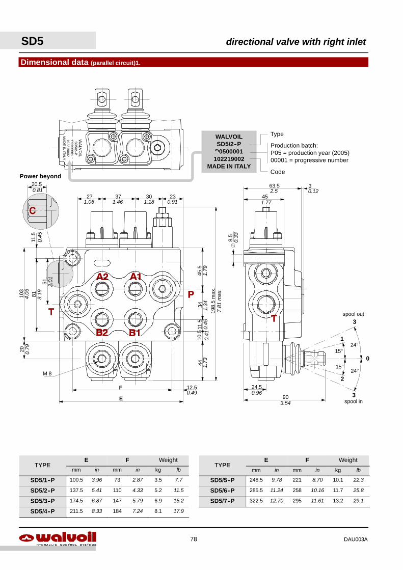
Dimensional data (parallel circuit)1.
3037
51
81
34
198.
5m
ax.
103
12.5
11.5
2345
.527
20
F
E
11.5
4410
.5
M 8
90
24.5
45
63.5 3
8.5
15°
15°
1
2
0
24°
24°
spool out3
3spool in
WA
LVO
ILS
D5/2
--PP
0200001102219002
MA
DE
INITA
LY
20.5Power beyond
WALVOILSD5/2--P
P0500001102219002
MADE IN ITALYCode
Production batch:P05 = production year (2005)00001 = progressive number
Type
0.81
0.45
4.06
3.19
2.01
0.79
0.49
1.73
0.41
0.45
1.34
1.79
1.06 1.46 1.18 0.91
7.81
max
.
0.33
1.77
2.5 0.12
0.96
3.54
SD5 directional valve with right inlet
78 DAU003A
TYPEE F Weight
TYPEE F Weight
TYPEmm in mm in kg lb
TYPEmm in mm in kg lb
SD5/1--P 100.5 3.96 73 2.87 3.5 7.7 SD5/5--P 248.5 9.78 221 8.70 10.1 22.3
SD5/2--P 137.5 5.41 110 4.33 5.2 11.5 SD5/6--P 285.5 11.24 258 10.16 11.7 25.8
SD5/3--P 174.5 6.87 147 5.79 6.9 15.2 SD5/7--P 322.5 12.70 295 11.61 13.2 29.1
SD5/4--P 211.5 8.33 184 7.24 8.1 17.9
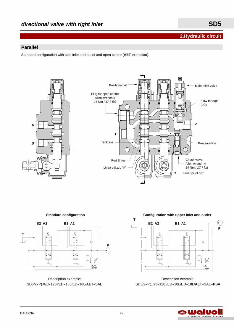
2.Hydraulic circuit
Lever pivot box
Check valveAllen wrench 424 Nm / 17.7 lbft
Configuration with upper inlet and outlet
PB1 A1B2 A2
T
Description example:
SD5/2--P(JG3--120)/ED--18L/ED--18L/AET--SAE--PSA
120
P
B1 A1B2 A2
T
Description example:
SD5/2--P(JG3--120)/ED--18L/ED--18L/AET--SAE
120
Standard configuration
Tank line
Flow through(LC)
Pressure line
Linea utilizzo ”A”
Port B line
Positioner kit
Plug for open centreAllen wrench 8
24 Nm / 17.7 lbft
Main relief valve
A
B
P
T
ParallelStandard configuration with side inlet and outlet and open centre (AET execution).
1750 1750
directional valve with right inlet SD5
79DAU003A
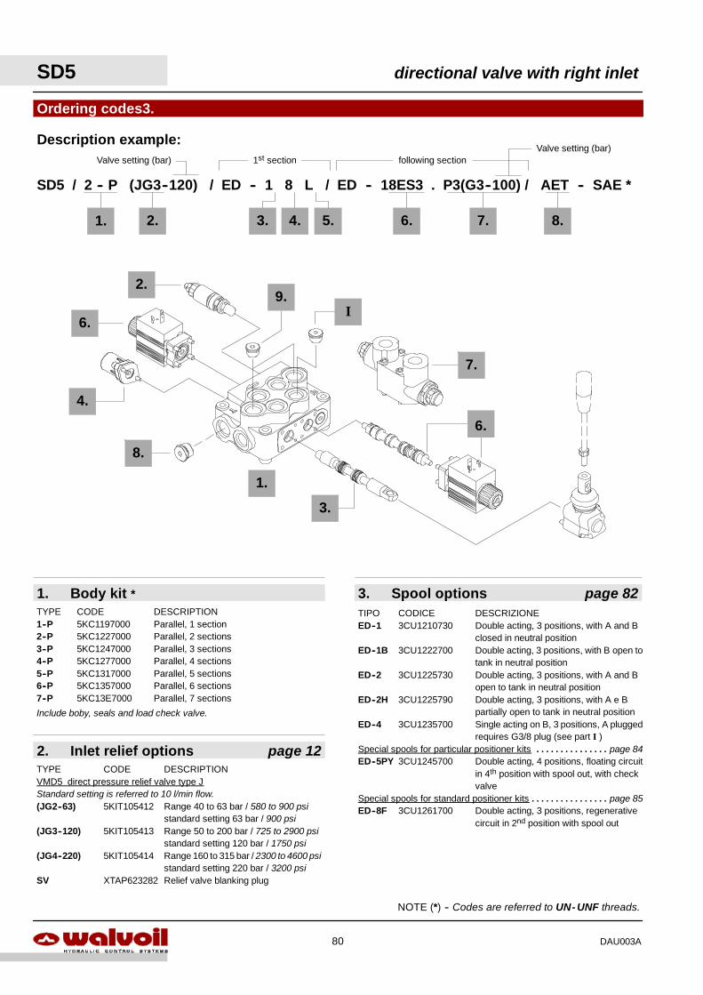
SD5 directional valve with right inlet
80 DAU003A
2. Inlet relief options page 12
1. Body kit *
Ordering codes3.
2.
SD5 / 2 -- P (JG3--120) / ED -- 1 8 L / ED -- 18ES3 . P3(G3--100) / AET -- SAE *
TYPE CODE DESCRIPTION1--P 5KC1197000 Parallel, 1 section2--P 5KC1227000 Parallel, 2 sections3--P 5KC1247000 Parallel, 3 sections4--P 5KC1277000 Parallel, 4 sections5--P 5KC1317000 Parallel, 5 sections6--P 5KC1357000 Parallel, 6 sections7--P 5KC13E7000 Parallel, 7 sections
TYPE CODE DESCRIPTIONVMD5 direct pressure relief valve type JStandard setting is referred to 10 l/min flow.(JG2--63) 5KIT105412 Range 40 to 63 bar / 580 to 900 psi
standard setting 63 bar / 900 psi(JG3--120) 5KIT105413 Range 50 to 200 bar / 725 to 2900 psi
standard setting 120 bar / 1750 psi(JG4--220) 5KIT105414 Range 160 to 315 bar / 2300 to 4600 psi
standard setting 220 bar / 3200 psiSV XTAP623282 Relief valve blanking plug
4. 5.
Include boby, seals and load check valve.
1st section following section
Description example:
1. 3.
3. Spool options page 82TIPO CODICE DESCRIZIONEED--1 3CU1210730 Double acting, 3 positions, with A and B
closed in neutral positionED--1B 3CU1222700 Double acting, 3 positions, with B open to
tank in neutral positionED--2 3CU1225730 Double acting, 3 positions, with A and B
open to tank in neutral positionED--2H 3CU1225790 Double acting, 3 positions, with A e B
partially open to tank in neutral positionED--4 3CU1235700 Single acting on B, 3 positions, A plugged
requires G3/8 plug (see part I )Special spools for particular positioner kits page 84. . . . . . . . . . . . . . .ED--5PY 3CU1245700 Double acting, 4 positions, floating circuit
in 4th position with spool out, with checkvalve
Special spools for standard positioner kits page 85. . . . . . . . . . . . . . . .ED--8F 3CU1261700 Double acting, 3 positions, regenerative
circuit in 2nd position with spool out
NOTE (*) -- Codes are referred to UN- UNF threads.
7.6. 8.
Valve setting (bar)Valve setting (bar)
6.
4.
8.
9.I
2.
1.
3.
6.
7.
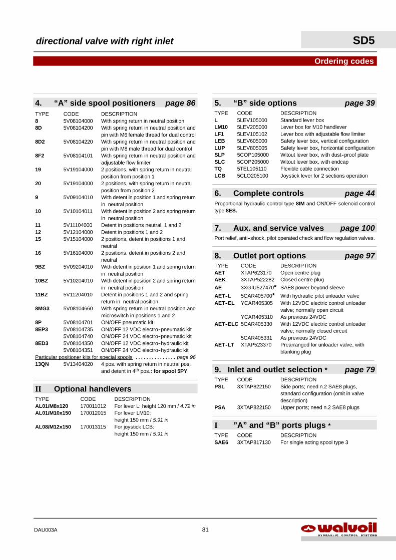
directional valve with right inlet SD5
81DAU003A
II Optional handleversTYPE CODE DESCRIPTIONAL01/M8x120 170011012 For lever L: height 120 mm / 4.72 inAL01/M10x150 170012015 For lever LM10:
height 150 mm / 5.91 inAL08/M12x150 170013115 For joystick LCB:
height 150 mm / 5.91 in
7. Aux. and service valves page 100
8. Outlet port options page 97TYPE CODE DESCRIPTIONAET XTAP623170 Open centre plugAEK 3XTAP522282 Closed centre plug
AE 3XGIU527470* SAE8 power beyond sleeve
AET--L 5CAR405700* With hydraulic pilot unloader valveAET--EL YCAR405305 With 12VDC electric control unloader
valve; normally open circuitYCAR405310 As previous 24VDC
AET--ELC 5CAR405330 With 12VDC electric control unloadervalve; normally closed circuit
5CAR405331 As previous 24VDCAET--LT XTAP523370 Prearranged for unloader valve, with
blanking plug
9. Inlet and outlet selection * page 79
4. “A” side spool positioners page 86
Ordering codes
TYPE CODE DESCRIPTION8 5V08104000 With spring return in neutral position8D 5V08104200 With spring return in neutral position and
pin with M6 female thread for dual control8D2 5V08104220 With spring return in neutral position and
pin with M8 male thread for dual control8F2 5V08104101 With spring return in neutral position and
adjustable flow limiter19 5V19104000 2 positions, with spring return in neutral
position from position 120 5V19104000 2 positions, with spring return in neutral
position from position 29 5V09104010 With detent in position 1 and spring return
in neutral position10 5V10104011 With detent in position 2 and spring return
in neutral position11 5V11104000 Detent in positions neutral, 1 and 212 5V12104000 Detent in positions 1 and 215 5V15104000 2 positions, detent in positions 1 and
neutral16 5V16104000 2 positions, detent in positions 2 and
neutral9BZ 5V09204010 With detent in position 1 and spring return
in neutral position10BZ 5V10204010 With detent in position 2 and spring return
in neutral position11BZ 5V11204010 Detent in positions 1 and 2 and spring
return in neutral position8MG3 5V08104660 With spring return in neutral position and
microswitch in positions 1 and 28P 5V08104701 ON/OFF pneumatic kit8EP3 5V08104735 ON/OFF 12 VDC electro--pneumatic kit
5V08104740 ON/OFF 24 VDC electro--pneumatic kit8ED3 5V08104350 ON/OFF 12 VDC electro--hydraulic kit
5V08104351 ON/OFF 24 VDC electro--hydraulic kitParticular positioner kits for special spools page 96. . . . . . . . . . . . . . .13QN 5V13404020 4 pos. with spring return in neutral pos.
and detent in 4th pos.: for spool 5PY
TYPE CODE DESCRIPTIONPSL 3XTAP822150 Side ports; need n.2 SAE8 plugs,
standard configuration (omit in valvedescription)
PSA 3XTAP822150 Upper ports; need n.2 SAE8 plugs
Port relief, anti--shock, pilot operated check and flow regulation valves.
6. Complete controls page 44Proportional hydraulic control type 8IM and ON/OFF solenoid controltype 8ES.
5. “B” side options page 39TYPE CODE DESCRIPTIONL 5LEV105000 Standard lever boxLM10 5LEV205000 Lever box for M10 handleverLF1 5LEV105102 Lever box with adjustable flow limiterLEB 5LEV605000 Safety lever box, vertical configurationLUP 5LEV805005 Safety lever box, horizontal configurationSLP 5COP105000 Witout lever box, with dust--proof plateSLC 5COP205000 Witout lever box, with endcapTQ 5TEL105110 Flexible cable connectionLCB 5CLO205100 Joystick lever for 2 sections operation
I ”A” and “B” ports plugs *TYPE CODE DESCRIPTIONSAE6 3XTAP817130 For single acting spool type 3
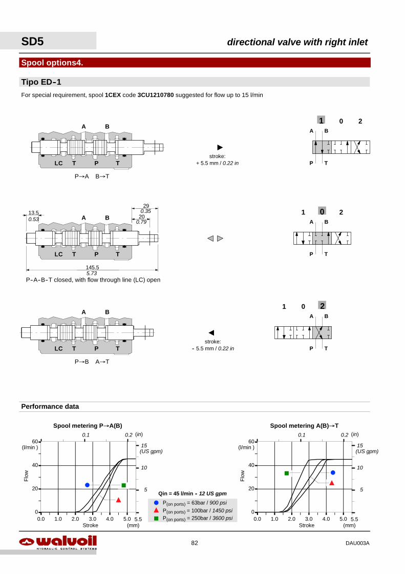
F
J
Y
P(on ports) = 63bar / 900 psiP(on ports) = 100bar / 1450 psiP(on ports) = 250bar / 3600 psi
Qin = 45 l/min -- 12 US gpm
0
20
40
60
0.0 1.0 2.0 3.0 4.0 5.00
20
40
60
0.0 1.0 2.0 3.0 4.0 5.0
Flo
w
Stroke (mm)
(l/min )
Spool metering A(B)→T
5.5
(in)0.1 0.2
Flo
w
Stroke
Spool metering P→A(B)
(mm)
(l/min )
5.5
(in)0.1 0.2
Performance data
F J
Y
FJ
Y
20
290.35
0.79
A
"
Tipo ED--1
Spool options4.
201
201
201A B
P T
A B
P T
A B
P T
For special requirement, spool 1CEX code 3CU1210780 suggested for flow up to 15 l/min
P--A--B--T closed, with flow through line (LC) open
145.5
13.5BA
TPLC T
P→A B→T
BA
TPLC T
P→B A→T
BA
TPLC T
5.73
0.53
stroke:+ 5.5 mm / 0.22 in
stroke:-- 5.5 mm / 0.22 in
5
10
15(US gpm)
5
10
15(US gpm)
SD5 directional valve with right inlet
82 DAU003A
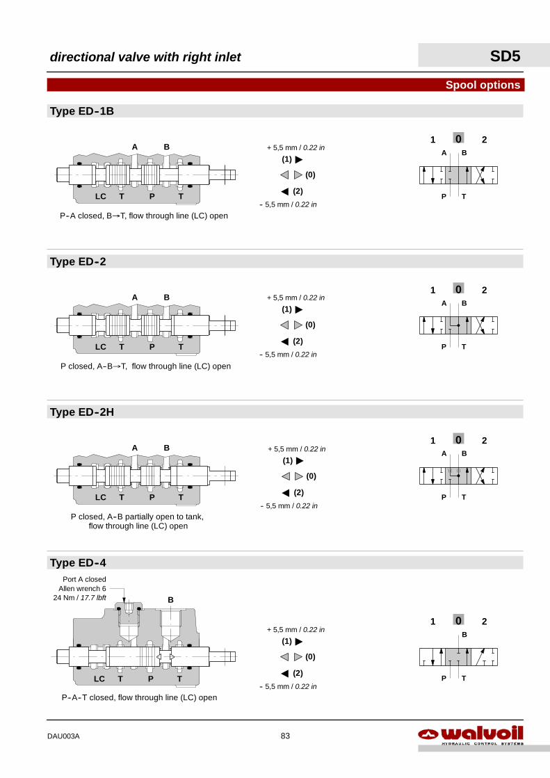
A
-- 5,5 mm / 0.22 in
"
+ 5,5 mm / 0.22 in
(0)
(1)
(2)
201A B
P T
Type ED--2H
Type ED--2
Type ED--1B
Spool options
Type ED--4
201A B
P T
P--A closed, B→T, flow through line (LC) open
P closed, A--B partially open to tank,flow through line (LC) open
BA
TPLC T
201A B
P T
P closed, A--B→T, flow through line (LC) open
BA
TPLC T
BA
TPLC T
B
TPLC T
P--A--T closed, flow through line (LC) open
201B
P T
Port A closedAllen wrench 6
24 Nm / 17.7 lbft
A
-- 5,5 mm / 0.22 in
"
+ 5,5 mm / 0.22 in
(0)
(1)
(2)
A
-- 5,5 mm / 0.22 in
"
+ 5,5 mm / 0.22 in
(0)
(1)
(2)
A
-- 5,5 mm / 0.22 in
"
+ 5,5 mm / 0.22 in
(0)
(1)
(2)
directional valve with right inlet SD5
83DAU003A
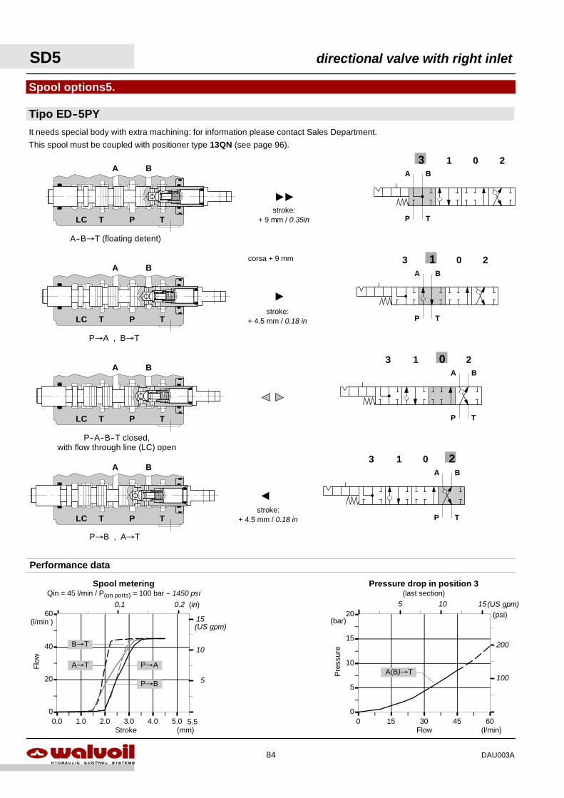
stroke:+ 9 mm / 0.35in
BA
TPLC T
BA
TPLC T
BA
TPLC T
013 2A B
P T
0
5
10
15
20
0 15 30 45 60
Pre
ssur
e
Flow (l/min)
(bar)
Pressure drop in position 3(last section)
A(B)→T
0
20
40
60
0.0 1.0 2.0 3.0 4.0 5.0
Flo
w
Stroke (mm)
(l/min )
5.5
P→AA→T
It needs special body with extra machining: for information please contact Sales Department.
This spool must be coupled with positioner type 13QN (see page 96).
Spool options5.
Tipo ED--5PY
Performance data
A--B→T (floating detent)
P→B , A→T
A
""
"
stroke:+ 4.5 mm / 0.18 in
corsa + 9 mm
P→A , B→T
P--A--B--T closed,with flow through line (LC) open
BA
TPLC T
013 2A B
P T
013 2A B
P T
013 2A B
P T
P→B
A→T
B→T
stroke:+ 4.5 mm / 0.18 in
Spool meteringQin = 45 l/min / P(on ports) = 100 bar -- 1450 psi
(in)0.1 0.2(psi)
200
1005
10
15(US gpm)
5 10 15(US gpm)
SD5 directional valve with right inlet
84 DAU003A
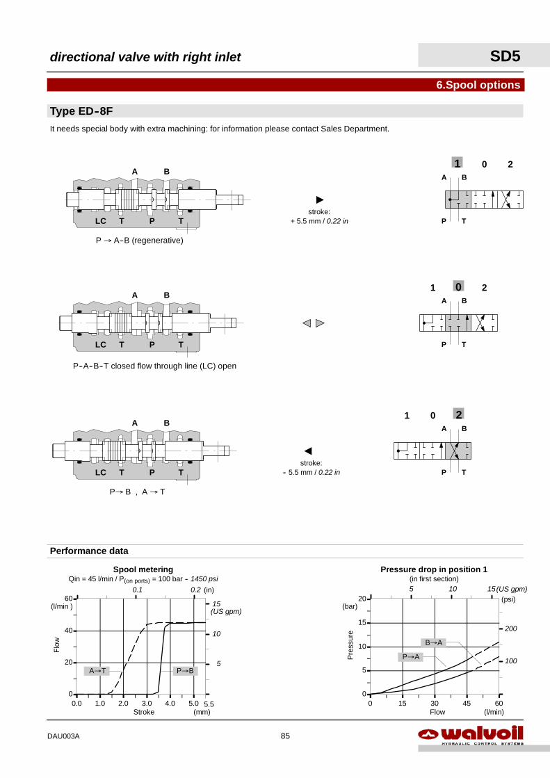
201A B
P T
Type ED--8F
6.Spool options
0
20
40
60
0.0 1.0 2.0 3.0 4.0 5.0
Flo
w
Stroke (mm)
(l/min )
201
201A B
P T
Performance data
A B
P T
5.5
P--A--B--T closed flow through line (LC) open
P→ B , A → T
It needs special body with extra machining: for information please contact Sales Department.
P → A--B (regenerative)
0
5
10
15
20
0 15 30 45 60
Pre
ssur
e
Flow (l/min)
(bar)
Pressure drop in position 1(in first section)
P→A
B→A
P→BA→T
BA
TPLC T
BA
TPLC T
BA
TPLC T
"
stroke:+ 5.5 mm / 0.22 in
A
stroke:-- 5.5 mm / 0.22 in
Spool meteringQin = 45 l/min / P(on ports) = 100 bar -- 1450 psi
0.1 0.2(psi)
200
100
(in)
5
10
15(US gpm)
5 10 15(US gpm)
directional valve with right inlet SD5
85DAU003A
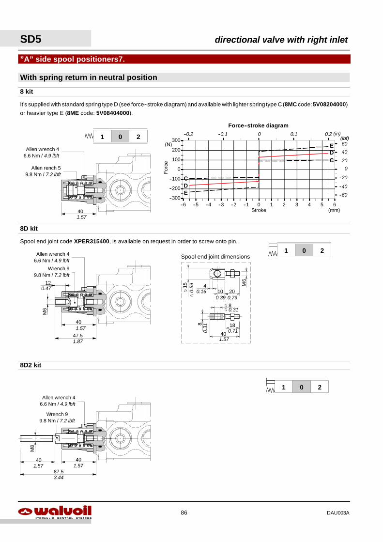
10
40
18
204 M
6
15
8
8
Spool end joint dimensions
0.160.39 0.79
0.31
0.71
1.57
0.31
0.59
--300
--200
--100
0
100
200
300
--6 --5 --4 --3 --2 --1 0 1 2 3 4 5 6Stroke
For
ce
(mm)
(N)
Force--stroke diagram
D
DE
C
C
E
0.1 0.2 (in)
40
20
(lbf)--0.1--0.2 0
60
0
--40
--20
--60
With spring return in neutral position
”A” side spool positioners7.
8 kit
8D kit
8D2 kit
201
201
201
It’s supplied with standard spring type D (see force--stroke diagram) and available with lighter spring type C (8MC code:5V08204000)
or heavier type E (8ME code: 5V08404000).
Spool end joint code XPER315400, is available on request in order to screw onto pin.
40
M6
40
47.5
M8
40
87.5
40
Allen wrench 46.6 Nm / 4.9 lbft
Allen rench 59.8 Nm / 7.2 lbft
1.57
1.57
1.87
120.47
Wrench 99.8 Nm / 7.2 lbft
Allen wrench 46.6 Nm / 4.9 lbft
Wrench 99.8 Nm / 7.2 lbft
Allen wrench 46.6 Nm / 4.9 lbft
1.57 1.57
3.44
SD5 directional valve with right inlet
86 DAU003A
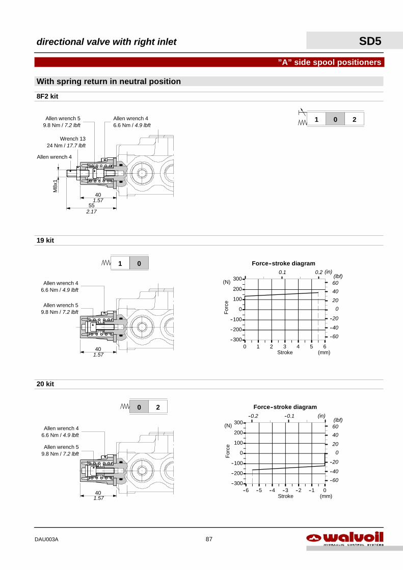
--300
--200
--100
0
100
200
300
--6 --5 --4 --3 --2 --1 0Stroke
For
ce
(mm)
(N)
Force--stroke diagram(in)
40
20
60
0
--40
--20
--60
(lbf)--0.1--0.2
--300
--200
--100
0
100
200
300
0 1 2 3 4 5 6Stroke
For
ce
(mm)
(N)
Force--stroke diagram(in)
40
20
60
0
--40
--20
--60
(lbf)0.1 0.2
201
With spring return in neutral position
”A” side spool positioners
8F2 kit
19 kit
55
M8x
1
40
40
20 kit
01
40
20
2.17
1.57
Allen wrench 59.8 Nm / 7.2 lbft
Allen wrench 4
Wrench 1324 Nm / 17.7 lbft
Allen wrench 46.6 Nm / 4.9 lbft
Allen wrench 46.6 Nm / 4.9 lbft
Allen wrench 59.8 Nm / 7.2 lbft
1.57
Allen wrench 59.8 Nm / 7.2 lbft
Allen wrench 46.6 Nm / 4.9 lbft
1.57
directional valve with right inlet SD5
87DAU003A
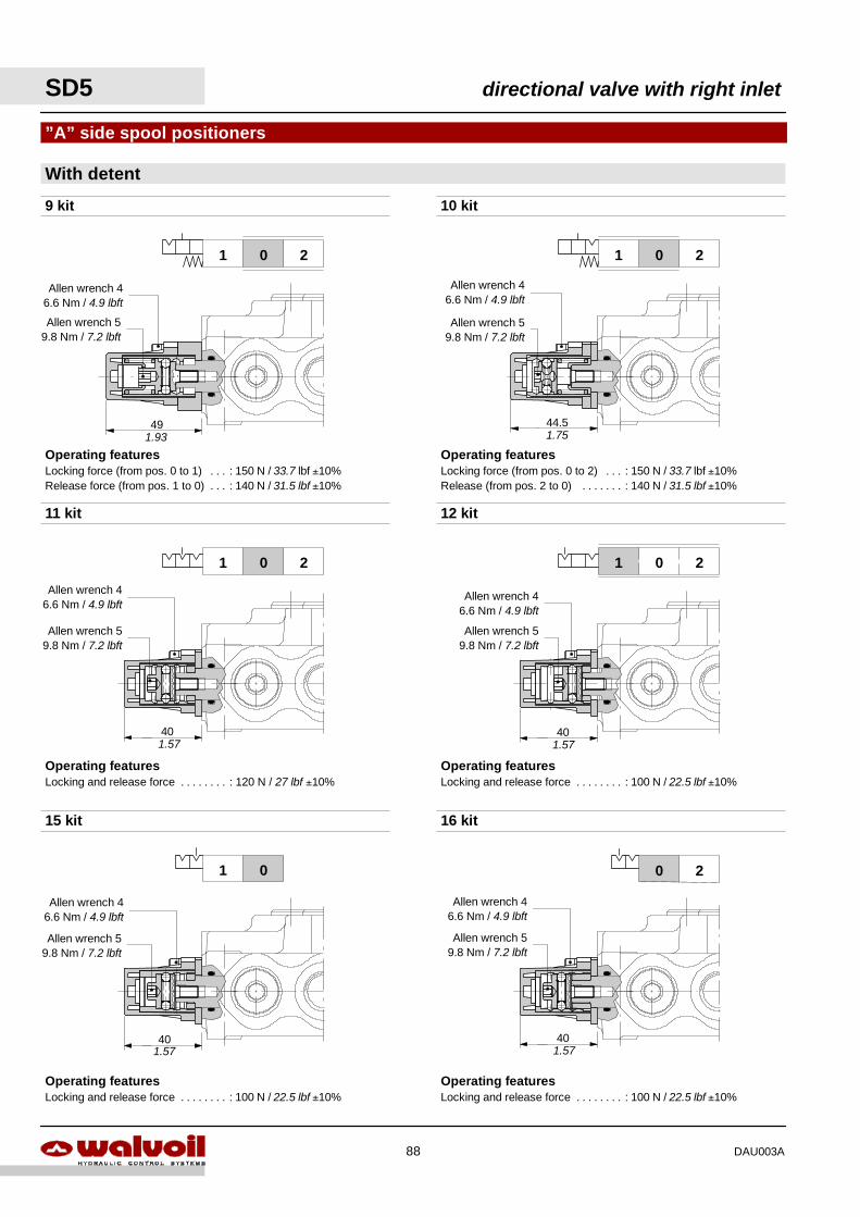
Operating featuresLocking and release force : 100 N / 22.5 lbf ±10%. . . . . . . .
Operating featuresLocking and release force : 100 N / 22.5 lbf ±10%. . . . . . . .
Operating featuresLocking and release force : 100 N / 22.5 lbf ±10%. . . . . . . .
Operating featuresLocking and release force : 120 N / 27 lbf ±10%. . . . . . . .
Operating featuresLocking force (from pos. 0 to 2) : 150 N / 33.7 lbf ±10%. . .Release (from pos. 2 to 0) : 140 N / 31.5 lbf ±10%. . . . . . .
Operating featuresLocking force (from pos. 0 to 1) : 150 N / 33.7 lbf ±10%. . .Release force (from pos. 1 to 0) : 140 N / 31.5 lbf ±10%. . .
40
201201
201
With detent
”A” side spool positioners
9 kit
11 kit
15 kit
49 44.5
40
10 kit
201
12 kit
01
40
20
40
16 kit
Allen wrench 59.8 Nm / 7.2 lbft
Allen wrench 46.6 Nm / 4.9 lbft
1.93
Allen wrench 46.6 Nm / 4.9 lbft
Allen wrench 59.8 Nm / 7.2 lbft
1.75
Allen wrench 59.8 Nm / 7.2 lbft
Allen wrench 46.6 Nm / 4.9 lbft
1.57
Allen wrench 46.6 Nm / 4.9 lbft
Allen wrench 59.8 Nm / 7.2 lbft
1.57
Allen wrench 59.8 Nm / 7.2 lbft
Allen wrench 46.6 Nm / 4.9 lbft
1.57
Allen wrench 59.8 Nm / 7.2 lbft
Allen wrench 46.6 Nm / 4.9 lbft
1.57
SD5 directional valve with right inlet
88 DAU003A
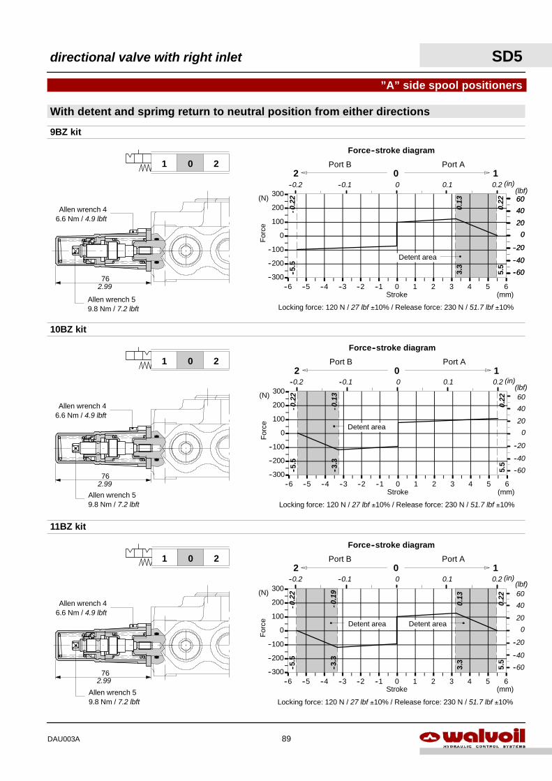
--300
--200
--100
0
100
200
300
--6 --5 --4 --3 --2 --1 0 1 2 3 4 5 6Stroke
For
ce
(mm)
(N)
Force--stroke diagram
Locking force: 120 N / 27 lbf ±10% / Release force: 230 N / 51.7 lbf ±10%
2 0 1Port B Port A
--3.3
--5.5
5.5
3.3
Detent area
40
20
(lbf)60
0
--40
--20
--60
0.1 0.2 (in)--0.1--0.2 0
-0.1
9
-0.2
2
0.22
0.13
Detent area
--300
--200
--100
0
100
200
300
--6 --5 --4 --3 --2 --1 0 1 2 3 4 5 6Stroke
For
ce
(mm)
(N)
Force--stroke diagram
Locking force: 120 N / 27 lbf ±10% / Release force: 230 N / 51.7 lbf ±10%
Detent area
2 0 1Port B Port A
--3.3
--5.5
5.5
40
20
(lbf)60
0
--40
--20
--60
0.1 0.2 (in)--0.1--0.2 0
-0.1
3
-0.2
2
0.22
--300
--200
--100
0
100
200
300
--6 --5 --4 --3 --2 --1 0 1 2 3 4 5 6Stroke
For
ce
(mm)
(N)
Force--stroke diagram
Locking force: 120 N / 27 lbf ±10% / Release force: 230 N / 51.7 lbf ±10%
Detent area
2 0 1Port B Port A
3.3
0.22
--5.5
40
20
(lbf)60
0
--40
--20
--60
0.1 0.2 (in)--0.1--0.2 0
-0.2
2
40
20
60
0
--40
--20
--605.5
0.13
With detent and sprimg return to neutral position from either directions
”A” side spool positioners
9BZ kit
10BZ kit
11BZ kit
201
201
201
76
76
76
Allen wrench 46.6 Nm / 4.9 lbft
Allen wrench 59.8 Nm / 7.2 lbft
Allen wrench 46.6 Nm / 4.9 lbft
Allen wrench 59.8 Nm / 7.2 lbft
Allen wrench 46.6 Nm / 4.9 lbft
Allen wrench 59.8 Nm / 7.2 lbft
2.99
2.99
2.99
directional valve with right inlet SD5
89DAU003A
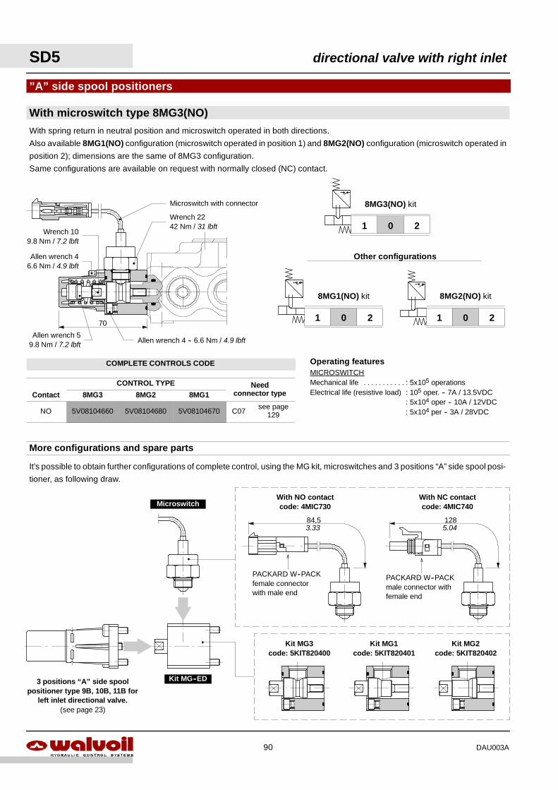
SD5 directional valve with right inlet
90 DAU003A
COMPLETE CONTROLS CODE
CONTROL TYPE NeedContact 8MG3 8MG2 8MG1
Needconnector type
NO 5V08104660 5V08104680 5V08104670 C07see page
129
PACKARD W--PACKmale connector withfemale end
PACKARD W--PACKfemale connectorwith male end
With NO contactcode: 4MIC730
With NC contactcode: 4MIC740
84,5 1283.33 5.04
It’s possible to obtain further configurations of complete control, using the MG kit, microswitches and 3 positions “A” side spool posi-
tioner, as following draw.
More configurations and spare parts
201
8MG1(NO) kit
201
201
Other configurations
8MG2(NO) kit
8MG3(NO) kit
Operating featuresMICROSWITCHMechanical life : 5x10⁵ operations. . . . . . . . . . .Electrical life (resistive load) : 105 oper. -- 7A / 13.5VDC
: 5x10⁴ oper -- 10A / 12VDC: 5x10⁴ per -- 3A / 28VDC
With microswitch type 8MG3(NO)
”A” side spool positioners
With spring return in neutral position and microswitch operated in both directions.
Also available 8MG1(NO) configuration (microswitch operated in position 1) and 8MG2(NO) configuration (microswitch operated in
position 2); dimensions are the same of 8MG3 configuration.
Same configurations are available on request with normally closed (NC) contact.
70
Microswitch with connector
Kit MG--ED
Microswitch
Kit MG3code: 5KIT820400
Kit MG1code: 5KIT820401
Kit MG2code: 5KIT820402
3 positions “A” side spoolpositioner type 9B, 10B, 11B for
left inlet directional valve.(see page 23)
Wrench 2242 Nm / 31 lbft
Allen wrench 59.8 Nm / 7.2 lbft Allen wrench 4 -- 6.6 Nm / 4.9 lbft
Allen wrench 46.6 Nm / 4.9 lbft
Wrench 109.8 Nm / 7.2 lbft
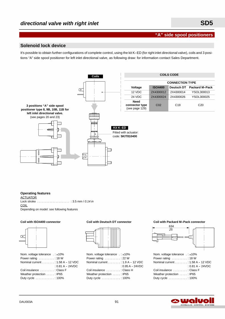
Operating featuresACTUATORLock stroke : 3.5 mm / 0.14 in. . . . . . . . . . . . . . . . . . . . .COILDepending on model: see following features
Solenoid lock device
“A” side spool positioners
3 positions “A” side spoolpositioner type 8, 9B, 10B, 11B for
left inlet directional valve.(see pages 20 and 23)
Fitted with actuator:code: 5KIT810400
Coils
Kit K--ED
Coil with ISO4400 connector
Nom. voltage tolerance : ±10%.Power rating : 18 W. . . . . . . . . .Nominal current : 1.58 A -- 12 VDC. . . . . . . .
: 0.81 A -- 24VDCCoil insulance : Class F. . . . . . . . .Weather protection : IP65. . . . .Duty cycle : 100%. . . . . . . . . . . .
Coil with Deutsch DT connector
Nom. voltage tolerance : ±10%.Power rating : 22 W. . . . . . . . . .Nominal current : 1.9 A -- 12 VDC. . . . . . . .
: 0.95 A -- 24VDCCoil insulance : Class H. . . . . . . . .Weather protection : IP65. . . . .Duty cycle : 100%. . . . . . . . . . . .
Coil with Packard M--Pack connector
Nom. voltage tolerance : ±10%.Power rating : 18 W. . . . . . . . . .Nominal current : 1.58 A -- 12 VDC. . . . . . . .
: 0.81 A -- 24VDCCoil insulance : Class F. . . . . . . . .Weather protection : IP65. . . . .Duty cycle : 100%. . . . . . . . . . . .
634
It’s possible to obtain further configurations of complete control, using the kit K--ED (for right inlet directional valve), coils and 3 posi-
tions “A” side spool positioner for left inlet directional valve, as following draw: for information contact Sales Department.
25
directional valve with right inlet SD5
91DAU003A
COILS CODE
CONNECTION TYPE
Voltage ISO4400 Deutsch DT Packard M--Pack
12 VDC 2X4300012 2X4300014 YSOL300013
24 VDC 2X4300024 2X4300026 YSOL300025
Needconnector type(see page 129)
C02 C19 C20
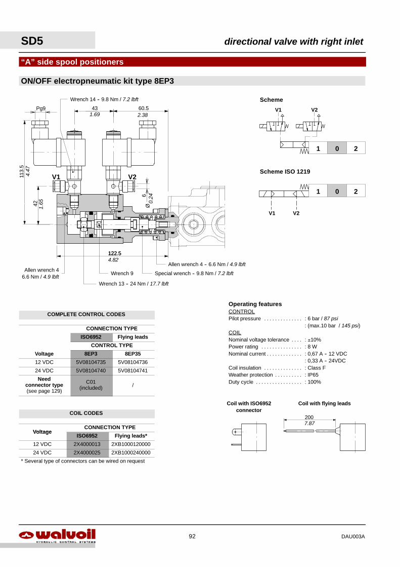
SD5 directional valve with right inlet
92 DAU003A
COMPLETE CONTROL CODES
CONNECTION TYPE
ISO6952 Flying leads
CONTROL TYPE
Voltage 8EP3 8EP35
12 VDC 5V08104735 5V08104736
24 VDC 5V08104740 5V08104741
Needconnector type(see page 129)
C01(included) /
COIL CODES
VoltageCONNECTION TYPE
VoltageISO6952 Flying leads*
12 VDC 2X4000013 2XB1000120000
24 VDC 2X4000025 2XB1000240000
* Several type of connectors can be wired on request
Wrench 14 -- 9.8 Nm / 7.2 lbft
42
113.
5
431.69
4.47
1.65
Coil with ISO6952connector
Coil with flying leads
2007.87
Operating featuresCONTROLPilot pressure : 6 bar / 87 psi. . . . . . . . . . . . . .
: (max.10 bar / 145 psi)COILNominal voltage tolerance : ±10%. . . .Power rating : 8 W. . . . . . . . . . . . . . .Nominal current : 0,67 A -- 12 VDC. . . . . . . . . . . . .
: 0,33 A -- 24VDCCoil insulation : Class F. . . . . . . . . . . . . .Weather protection : IP65. . . . . . . . . .Duty cycle : 100%. . . . . . . . . . . . . . . . .
ON/OFF electropneumatic kit type 8EP3
“A” side spool positioners
122.5
60.5
V1 V2
Pg9
Scheme ISO 1219
Scheme
201
V1 V2
201
V1 V2
6Ø
0.24
2.38
122.54.82
Special wrench -- 9.8 Nm / 7.2 lbft
Allen wrench 4 -- 6.6 Nm / 4.9 lbft
Wrench 9Allen wrench 4
6.6 Nm / 4.9 lbftWrench 13 -- 24 Nm / 17.7 lbft
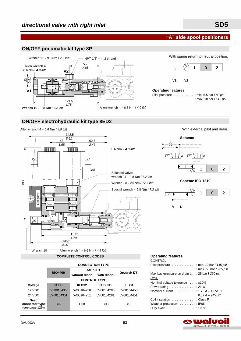
Operating featuresPilot pressure : min. 5.5 bar / 80 psi. . . . . . . . . . . .
: max. 10 bar / 145 psi
Col
lect
or
119.5
136.5
Coil
62.542
133
142.5
ON/OFF electrohydraulic kit type 8ED3
“A” side spool positioners
With external pilot and drain.
Operating featuresCONTROLPilot pressure : min. 10 bar / 145 psi. . . . . . . . . . . . . .
: max. 50 bar / 725 psiMax backpressure on drain L : 25 bar / 360 psi.COILNominal voltage tolerance : ±10%. . . .Power rating : 21 W. . . . . . . . . . . . . . .Nominal current : 1.75 A -- 12 VDC. . . . . . . . . . . . .
0.87 A -- 24VDCCoil insulation : Class F. . . . . . . . . . . . . .Weather protection : IP65. . . . . . . . . .Duty cycle : 100%. . . . . . . . . . . . . . . . .
121.5
55
23
V1
V2
NPT 1/8” -- nr.2 thread
Wrench 10 -- 9.8 Nm / 7.2 lbft
Allen wrench 46.6 Nm / 4.9 lbft
Wrench 11 -- 9.8 Nm / 7.2 lbft
ON/OFF pneumatic kit type 8PWith spring return to neutral position.
201
V1 V2
Allen wrench 4 -- 6.6 Nm / 4.9 lbft
2.16
4.78
0.91
Scheme ISO 1219
Scheme
201
201
V L
LV
1
Solenoid valve:wrench 24 -- 9.8 Nm / 7.2 lbft
6.6 Nm -- 4.9 lbft
Allen wrench 4 -- 6.6 Nm / 4.9 lbft
Special wrench -- 9.8 Nm / 7.2 lbft
Wrench 10 -- 24 Nm / 17.7 lbft
Wrench 10
Allen wrench 4 -- 6,6 Nm / 4.9 lbft
5.37
4.70
1.65 2.46
5.61
directional valve with right inlet SD5
93DAU003A
COMPLETE CONTROL CODES
CONNECTION TYPE
ISO4400AMP JPT
Deutsch DTISO4400without diodo with diodo
Deutsch DT
CONTROL TYPE
Voltage 8ED3 8ED32 8ED32D 8ED34
12 VDC 5V080104350 5V08104250 5V08104280 5V08104450
24 VDC 5V08104351 5V08104251 5V08104281 5V08104451
Needconnector type(see page 129))
C02 C08 C08 C19
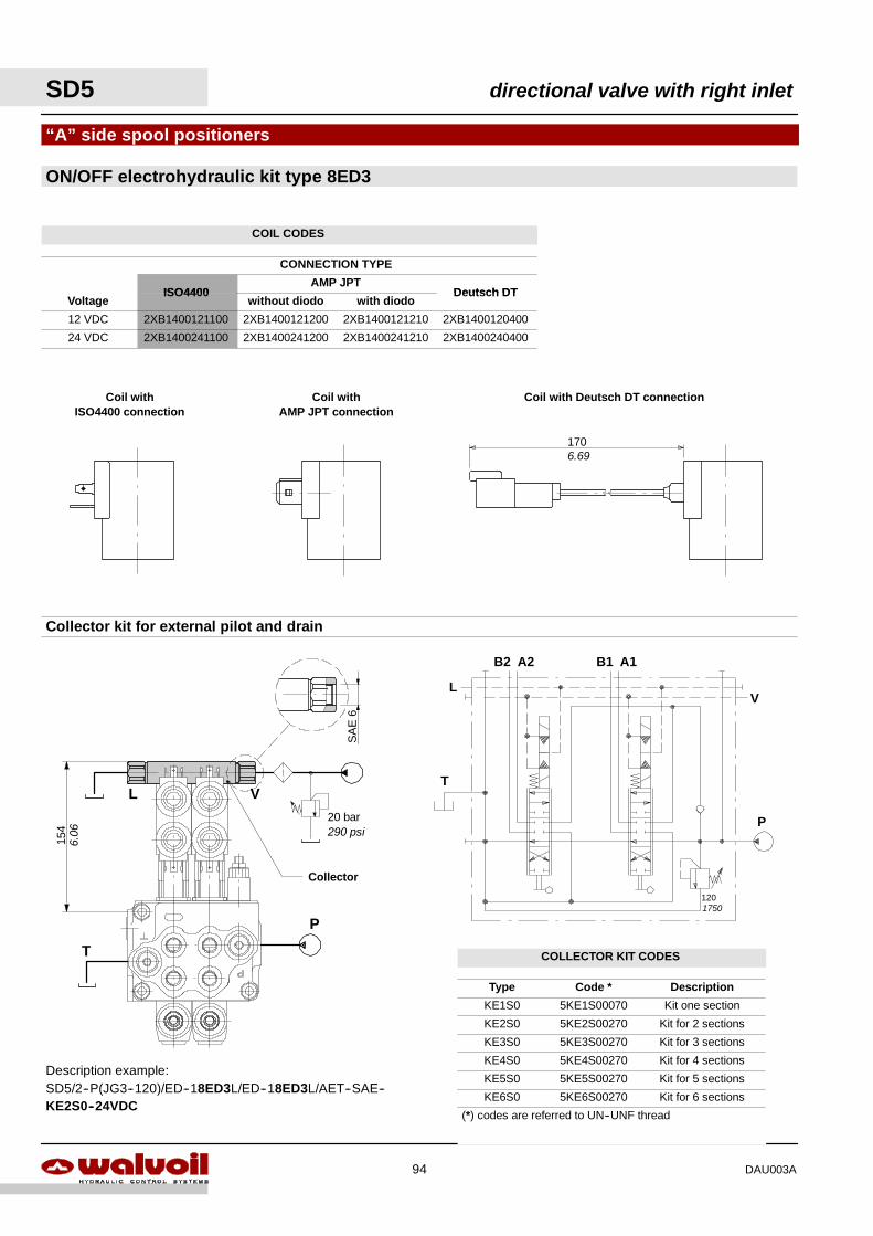
Collector kit for external pilot and drain
Coil withISO4400 connection
Coil withAMP JPT connection
Coil with Deutsch DT connection
ON/OFF electrohydraulic kit type 8ED3
“A” side spool positioners
V20 bar290 psi
L
Collector
P
T
154
Description example:SD5/2--P(JG3--120)/ED--18ED3L/ED--18ED3L/AET--SAE--KE2S0--24VDC
P
B1 A1B2 A2
T
120
VL
1706.69
1750
6.06
SA
E6
SD5 directional valve with right inlet
94 DAU003A
COIL CODES
CONNECTION TYPE
ISO4400AMP JPT
Deutsch DTVoltage
ISO4400without diodo with diodo
Deutsch DT
12 VDC 2XB1400121100 2XB1400121200 2XB1400121210 2XB1400120400
24 VDC 2XB1400241100 2XB1400241200 2XB1400241210 2XB1400240400
COLLECTOR KIT CODES
Type Code * Description
KE1S0 5KE1S00070 Kit one section
KE2S0 5KE2S00270 Kit for 2 sections
KE3S0 5KE3S00270 Kit for 3 sections
KE4S0 5KE4S00270 Kit for 4 sections
KE5S0 5KE5S00270 Kit for 5 sections
KE6S0 5KE6S00270 Kit for 6 sections
(*) codes are referred to UN--UNF thread
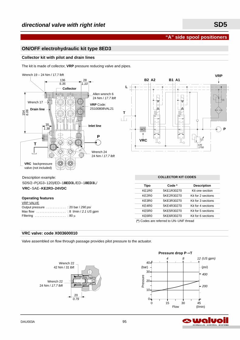
Pressure drop P→T
0
10
20
30
40
0 15 30 45Flow
Pre
ssur
e
(l/min)
(bar)
400
200
(psi)
4 8 (US gpm)12
“A” side spool positioners
Collector kit with pilot and drain lines
The kit is made of collector, VRP pressure reducing valve and pipes.
ON/OFF electrohydraulic kit type 8ED3
VRC valve: code X003600010
Valve assembled on flow through passage provides pilot pressure to the actuator.
35
154
136 28
Collector
Inlet line
Drain line
T
P
Wrench 19 -- 24 Nm / 17.7 lbft
Wrench 2424 Nm / 17.7 lbft
Wrench 17VRP Code:2S100808VAL21
Allen wrench 624 Nm / 17.7 lbft
VRC backpressurevalve (not included)
Description example:
SD5/2--P(JG3--120)/ED--18ED3L/ED--18ED3L/
VRC--SAE--KE2R3--24VDC
P
B1 A1B2 A2
T
120
L
VRP
VRC
Wrench 2242 Nm / 31 lbft
20
Wrench 2224 Nm / 17.7 lbft
5.35 1.10
1.38
6.06
Operating featuresVRP VALVEOutput pressure : 20 bar / 290 psi. . . . . . . . . . . .Max flow : 8 l/min / 2.1 US gpm. . . . . . . . . . . . . . . . . .Filtering : 80 µ. . . . . . . . . . . . . . . . . . .
1750
0.79
directional valve with right inlet SD5
95DAU003A
COLLECTOR KIT CODES
Tipo Code * Description
KE1R0 5KE1R30270 Kit one section
KE2R0 5KE2R30270 Kit for 2 sections
KE3R0 5KE3R30270 Kit for 3 sections
KE4R0 5KE4R30270 Kit for 4 sections
KE5R0 5KE5R30270 Kit for 5 sections
KE6R0 5KE6R30270 Kit for 6 sections
(*) Codes are referred to UN--UNF thread
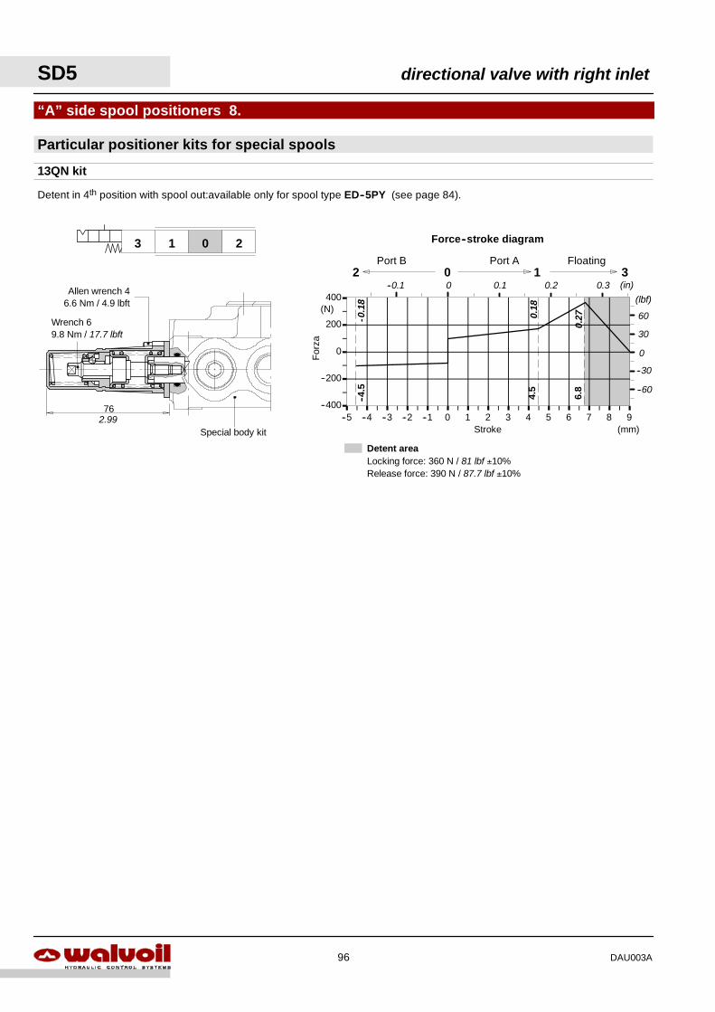
Detent areaLocking force: 360 N / 81 lbf ±10%Release force: 390 N / 87.7 lbf ±10%
--400
--200
0
200
400
--5 --4 --3 --2 --1 0 1 2 3 4 5 6 7 8 9Stroke
For
za
(mm)
(N)
Force--stroke diagram
2 0 1Port B Port A
3
--4.5
4.5
Floating
6.8
60
30
(lbf)
0
--60
--30
(in)0.1 0.20 0.3--0.1
-0.1
8
0.18
0.27
Particular positioner kits for special spools
“A” side spool positioners 8.
13QN kit
Detent in 4th position with spool out:available only for spool type ED--5PY (see page 84).
2013
76
Special body kit
Allen wrench 46.6 Nm / 4.9 lbft
Wrench 69.8 Nm / 17.7 lbft
2.99
SD5 directional valve with right inlet
96 DAU003A
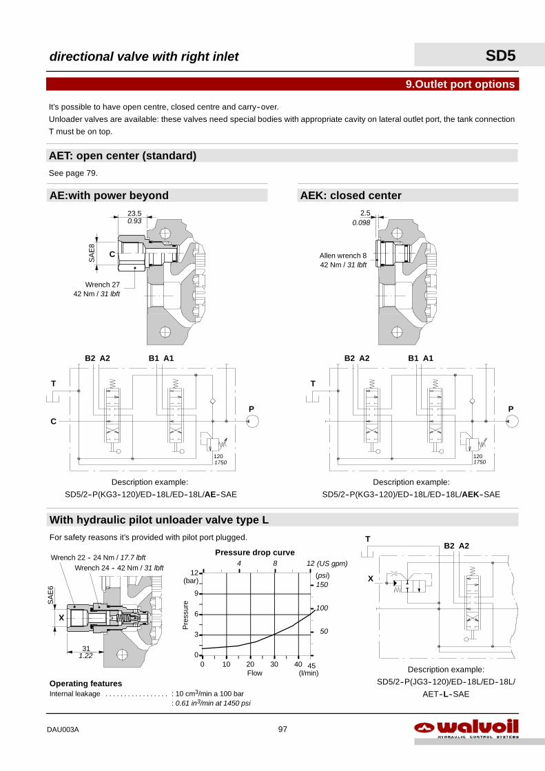
0
3
6
9
12
0 10 20 30 40
Pressure drop curve
Flow
Pre
ssur
e
(l/min)
(bar)
45
(psi)150
100
50
4 8 (US gpm)12
Operating featuresInternal leakage : 10 cm3/min a 100 bar. . . . . . . . . . . . . . . . .
: 0.61 in3/min at 1450 psi
AE:with power beyond
AET: open center (standard)
9.Outlet port options
See page 79.
Description example:
SD5/2--P(KG3--120)/ED--18L/ED--18L/AE--SAE
Description example:
SD5/2--P(KG3--120)/ED--18L/ED--18L/AEK--SAE
Wrench 2742 Nm / 31 lbft
C
2.5
Allen wrench 842 Nm / 31 lbft
With hydraulic pilot unloader valve type LFor safety reasons it’s provided with pilot port plugged.
X
B2 A2T
Description example:
SD5/2--P(JG3--120)/ED--18L/ED--18L/
AET--L--SAE
X
AEK: closed center
It’s possible to have open centre, closed centre and carry--over.
Unloader valves are available: these valves need special bodies with appropriate cavity on lateral outlet port, the tank connection
T must be on top.
P
B1 A1B2 A2
T
120
C
P
B1 A1B2 A2
T
120
0.098
Wrench 24 -- 42 Nm / 31 lbft
1750 1750
23.50.93
SA
E8
31
SA
E6
1.22
Wrench 22 -- 24 Nm / 17.7 lbft
directional valve with right inlet SD5
97DAU003A
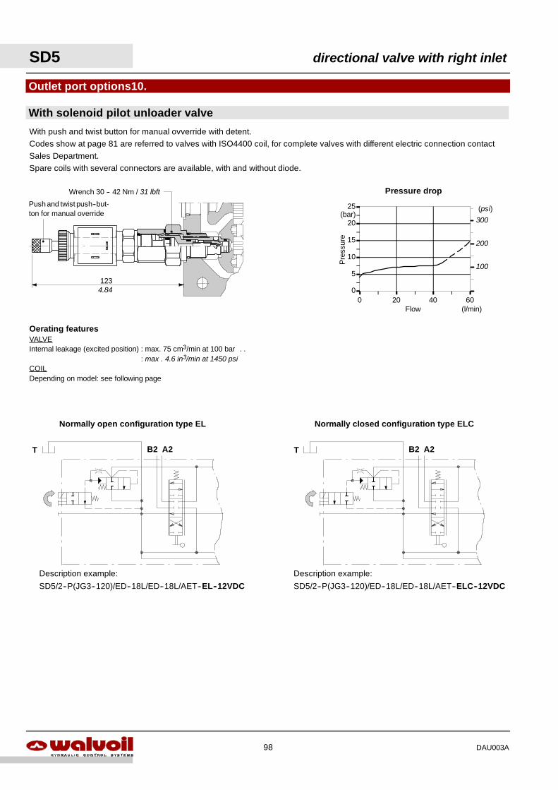
With push and twist button for manual ovverride with detent.Codes show at page 81 are referred to valves with ISO4400 coil, for complete valves with different electric connection contactSales Department.Spare coils with several connectors are available, with and without diode.
Oerating featuresVALVEInternal leakage (excited position) : max. 75 cm3/min at 100 bar . .
: max . 4.6 in3/min at 1450 psiCOILDepending on model: see following page
0
5
10
15
20
25
0 20 40 60
Pressure drop
Flow
Pre
ssur
e
(l/min)
(bar)(psi)
300
200
100
Description example:
SD5/2--P(JG3--120)/ED--18L/ED--18L/AET--ELC--12VDC
With solenoid pilot unloader valve
Outlet port options10.
Description example:
SD5/2--P(JG3--120)/ED--18L/ED--18L/AET--EL--12VDC
123
Wrench 30 -- 42 Nm / 31 lbft
B2 A2T
Normally open configuration type EL
B2 A2T
Normally closed configuration type ELC
Push and twist push--but-ton for manual override
4.84
SD5 directional valve with right inlet
98 DAU003A
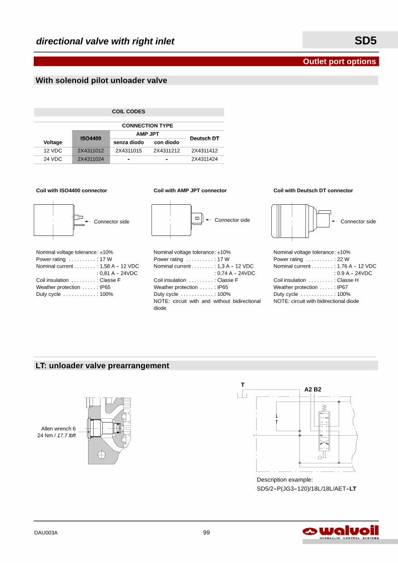
With solenoid pilot unloader valve
Outlet port options
LT: unloader valve prearrangement
A2 B2T
Description example:
SD5/2--P(JG3--120)/18L/18L/AET--LT
Allen wrench 624 Nm / 17.7 lbft
Nominal voltage tolerance: ±10%Power rating : 22 W. . . . . . . . . .Nominal current : 1.76 A -- 12 VDC. . . . . . . .
: 0.9 A -- 24VDCCoil insulation : Classe H. . . . . . . . .Weather protection : IP67. . . . .Duty cycle : 100%. . . . . . . . . . . .NOTE: circuit with bidirectional diode
Coil with Deutsch DT connector
Connector side
Nominal voltage tolerance: ±10%Power rating : 17 W. . . . . . . . . .Nominal current : 1,58 A -- 12 VDC. . . . . . . .
: 0,81 A -- 24VDCCoil insulation : Classe F. . . . . . . . .Weather protection : IP65. . . . .Duty cycle : 100%. . . . . . . . . . . .
Coil with ISO4400 connector
Connector side
Nominal voltage tolerance: ±10%Power rating : 17 W. . . . . . . . . .Nominal current : 1,3 A -- 12 VDC. . . . . . . .
: 0,74 A -- 24VDCCoil insulation : Classe F. . . . . . . . .Weather protection : IP65. . . . .Duty cycle : 100%. . . . . . . . . . . .NOTE: circuit with and without bidirectionaldiode
Coil with AMP JPT connector
Connector side
directional valve with right inlet SD5
99DAU003A
COIL CODES
CONNECTION TYPE
ISO4400AMP JPT
Deutsch DTVoltage
ISO4400senza diodo con diodo
Deutsch DT
12 VDC 2X4311012 2X4311015 2X4311212 2X4311412
24 VDC 2X4311024 -- -- 2X4311424
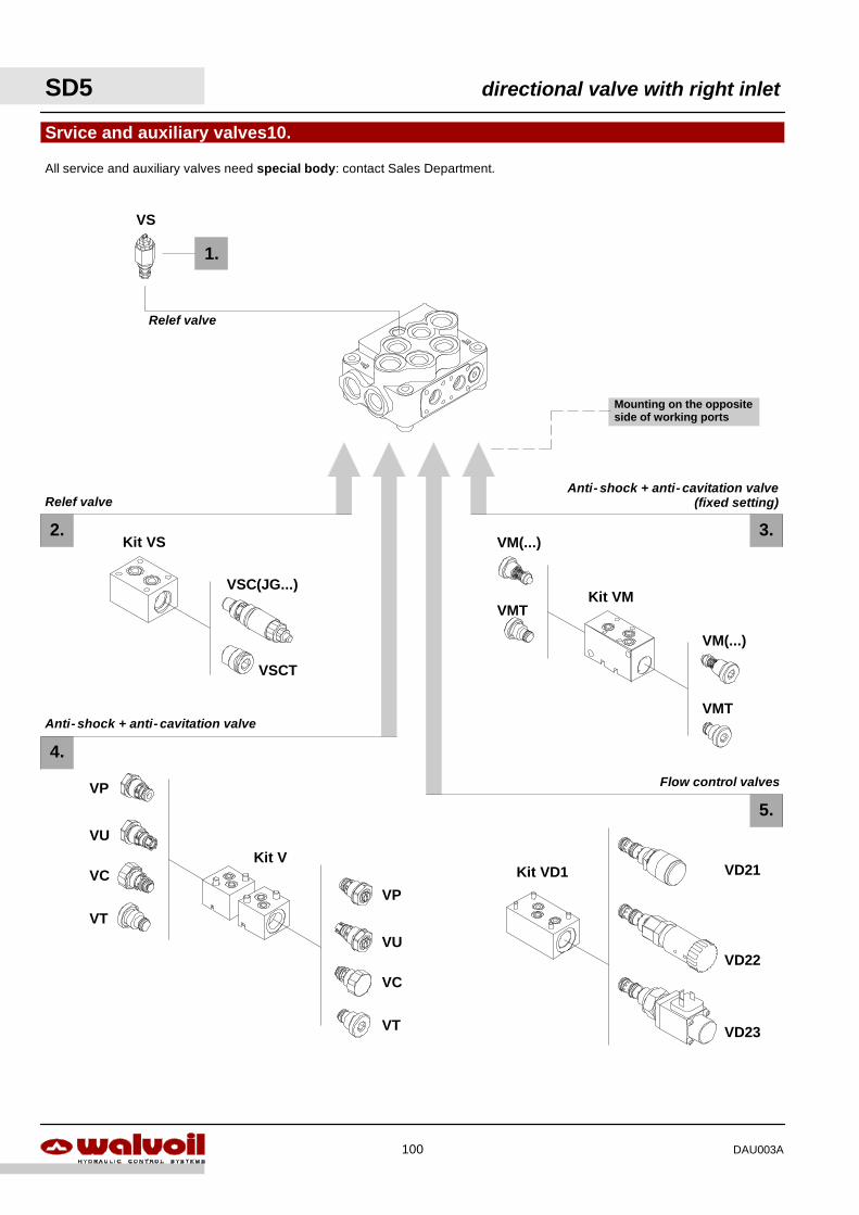
SD5 directional valve with right inlet
100 DAU003A
Mounting on the oppositeside of working ports
5.
3.
1.
2.
Srvice and auxiliary valves10.
4.
VS
Kit VM
All service and auxiliary valves need special body: contact Sales Department.
VM(...)
VMT
VM(...)
VMT
Kit V
VP
VU
VC
VT
VP
VU
VC
VT
Relef valve
Relef valve
Anti- shock + anti- cavitation valve
Anti- shock + anti- cavitation valve(fixed setting)
VSC(JG...)
VSCT
Kit VS
VD23
VD22
VD21Kit VD1
Flow control valves
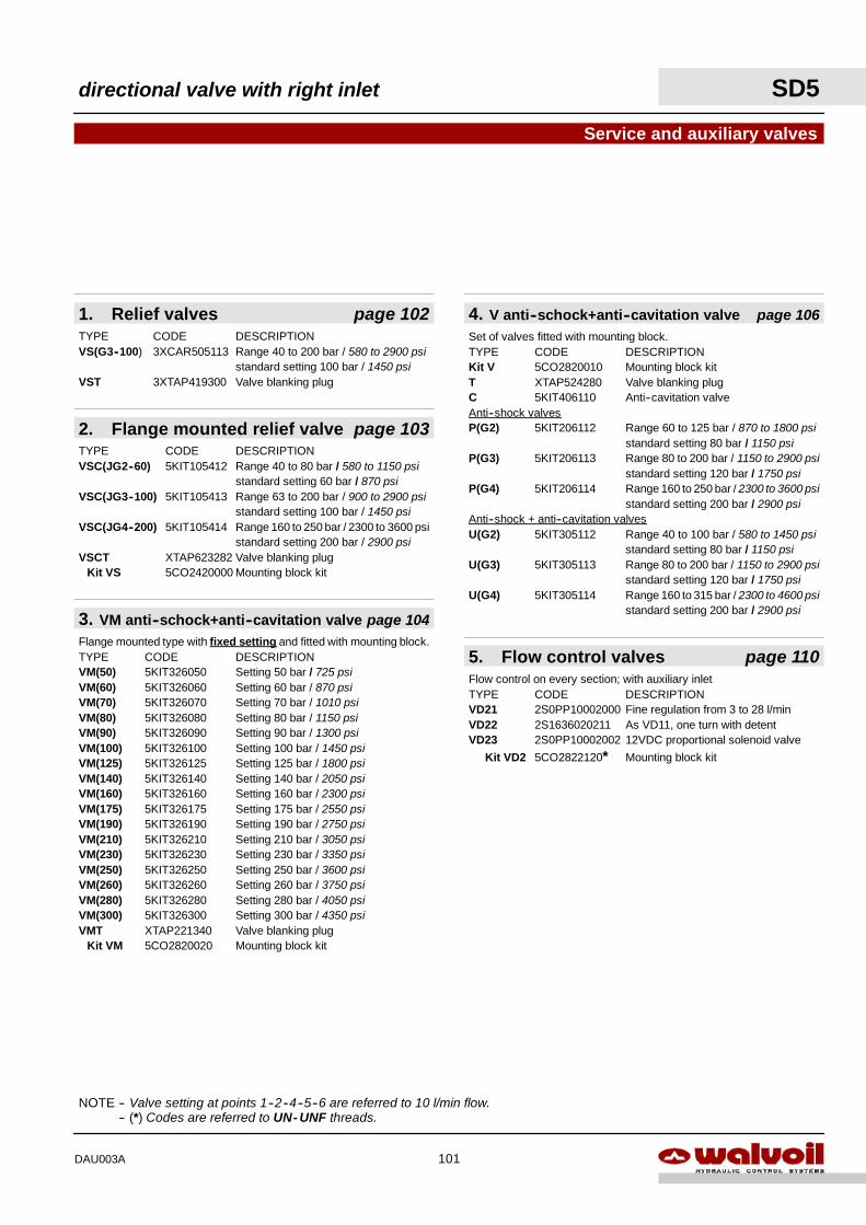
directional valve with right inlet SD5
101DAU003A
NOTE -- Valve setting at points 1--2--4--5--6 are referred to 10 l/min flow.NOTE -- (*) Codes are referred to UN- UNF threads.
3. VM anti--schock+anti--cavitation valve page 104Flange mounted type with fixed setting and fitted with mounting block.TYPE CODE DESCRIPTIONVM(50) 5KIT326050 Setting 50 bar / 725 psiVM(60) 5KIT326060 Setting 60 bar / 870 psiVM(70) 5KIT326070 Setting 70 bar / 1010 psiVM(80) 5KIT326080 Setting 80 bar / 1150 psiVM(90) 5KIT326090 Setting 90 bar / 1300 psiVM(100) 5KIT326100 Setting 100 bar / 1450 psiVM(125) 5KIT326125 Setting 125 bar / 1800 psiVM(140) 5KIT326140 Setting 140 bar / 2050 psiVM(160) 5KIT326160 Setting 160 bar / 2300 psiVM(175) 5KIT326175 Setting 175 bar / 2550 psiVM(190) 5KIT326190 Setting 190 bar / 2750 psiVM(210) 5KIT326210 Setting 210 bar / 3050 psiVM(230) 5KIT326230 Setting 230 bar / 3350 psiVM(250) 5KIT326250 Setting 250 bar / 3600 psiVM(260) 5KIT326260 Setting 260 bar / 3750 psiVM(280) 5KIT326280 Setting 280 bar / 4050 psiVM(300) 5KIT326300 Setting 300 bar / 4350 psiVMT XTAP221340 Valve blanking plug
Kit VM 5CO2820020 Mounting block kit
Service and auxiliary valves
1. Relief valves page 102TYPE CODE DESCRIPTIONVS(G3--100) 3XCAR505113 Range 40 to 200 bar / 580 to 2900 psi
standard setting 100 bar / 1450 psiVST 3XTAP419300 Valve blanking plug
5. Flow control valves page 110Flow control on every section; with auxiliary inletTYPE CODE DESCRIPTIONVD21 2S0PP10002000 Fine regulation from 3 to 28 l/minVD22 2S1636020211 As VD11, one turn with detentVD23 2S0PP10002002 12VDC proportional solenoid valve
Kit VD2 5CO2822120* Mounting block kit
2. Flange mounted relief valve page 103TYPE CODE DESCRIPTIONVSC(JG2--60) 5KIT105412 Range 40 to 80 bar / 580 to 1150 psi
standard setting 60 bar / 870 psiVSC(JG3--100) 5KIT105413 Range 63 to 200 bar / 900 to 2900 psi
standard setting 100 bar / 1450 psiVSC(JG4--200) 5KIT105414 Range 160 to 250 bar / 2300 to 3600 psi
standard setting 200 bar / 2900 psiVSCT XTAP623282 Valve blanking plug
Kit VS 5CO2420000 Mounting block kit
Set of valves fitted with mounting block.TYPE CODE DESCRIPTIONKit V 5CO2820010 Mounting block kitT XTAP524280 Valve blanking plugC 5KIT406110 Anti--cavitation valveAnti--shock valvesP(G2) 5KIT206112 Range 60 to 125 bar / 870 to 1800 psi
standard setting 80 bar / 1150 psiP(G3) 5KIT206113 Range 80 to 200 bar / 1150 to 2900 psi
standard setting 120 bar / 1750 psiP(G4) 5KIT206114 Range 160 to 250 bar / 2300 to 3600 psi
standard setting 200 bar / 2900 psiAnti--shock + anti--cavitation valvesU(G2) 5KIT305112 Range 40 to 100 bar / 580 to 1450 psi
standard setting 80 bar / 1150 psiU(G3) 5KIT305113 Range 80 to 200 bar / 1150 to 2900 psi
standard setting 120 bar / 1750 psiU(G4) 5KIT305114 Range 160 to 315 bar / 2300 to 4600 psi
standard setting 200 bar / 2900 psi
4. V anti--schock+anti--cavitation valve page 106
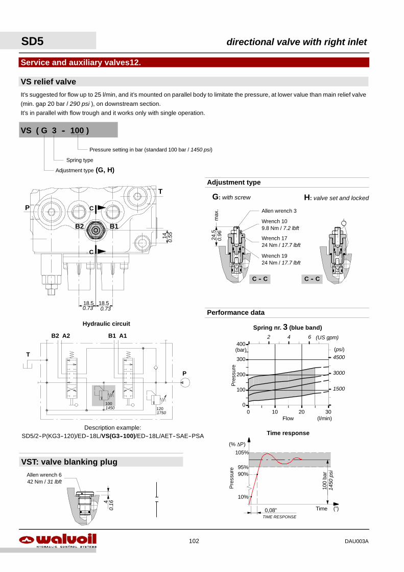
Spring nr. 3 (blue band)
0
100
200
300
400
0 10 20 30Flow
Pre
ssur
e
(l/min)
(bar) (psi)4500
3000
1500
2 4 6 (US gpm)
0,08”TIME RESPONSE
10%
100
bar90%
95%
105%
Pre
ssur
e
Time (”)
(% ∆P)
Time response
1450
psi
Adjustment type (G, H)
VS ( G 3 -- 100 )
Pressure setting in bar (standard 100 bar / 1450 psi)
VS relief valve
Service and auxiliary valves12.
It’s suggested for flow up to 25 l/min, and it’s mounted on parallel body to limitate the pressure, at lower value than main relief valve
(min. gap 20 bar / 290 psi ), on downstream section.
It’s in parallel with flow trough and it works only with single operation.
14
18.5 18.5
B2 B1
T
P
C
C
Hydraulic circuit
Description example:SD5/2--P(KG3--120)/ED--18L/VS(G3--100)/ED--18L/AET--SAE--PSA
Spring type
P
B1 A1B2 A2
T
120100
C -- C
24.5
max
.
G: with screw H: valve set and locked
C -- C
Adjustment type
Wrench 109.8 Nm / 7.2 lbft
Wrench 1724 Nm / 17.7 lbft
Wrench 1924 Nm / 17.7 lbft
Allen wrench 3
0.96
40.
16
VST: valve blanking plugAllen wrench 642 Nm / 31 lbft
17501450
Performance data0.73 0.73
0.55
SD5 directional valve with right inlet
102 DAU003A
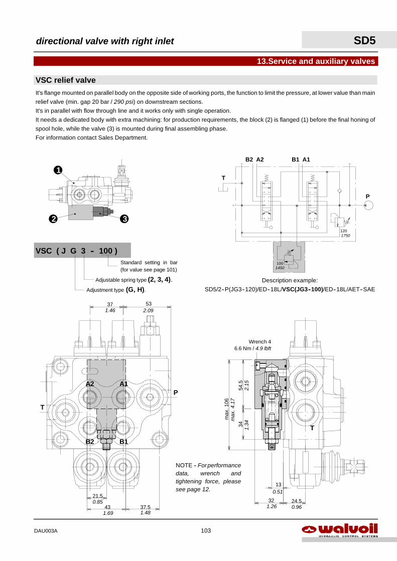
1
2 3
It’s flange mounted on parallel body on the opposite side of working ports, the function to limit the pressure, at lower value than main
relief valve (min. gap 20 bar / 290 psi) on downstream sections.
It’s in parallel with flow through line and it works only with single operation.
It needs a dedicated body with extra machining: for production requirements, the block (2) is flanged (1) before the final honing of
spool hole, while the valve (3) is mounted during final assembling phase.
For information contact Sales Department.
VSC relief valve
13.Service and auxiliary valves
P
B1 A1B2 A2
T
Description example:
SD5/2--P(JG3--120)/ED--18L/VSC(JG3--100)/ED--18L/AET--SAE
120
100
VSC ( J G 3 -- 100 )
Adjustment type (G, H).Adjustable spring type (2, 3, 4).
Standard setting in bar(for value see page 101)
NOTE -- Forperformancedata, wrench andtightening force, pleasesee page 12.
13
32
max
.106
24.5
Wrench 46.6 Nm / 4.9 lbft
3454
.5
21.5
43 37.5
5337
A2 A1
B2 B1
T
P
T
1750
1450
1.46 2.09
1.481.69
0.85
max
.4.1
7
2.15
1.34
1.26 0.96
0.51
directional valve with right inlet SD5
103DAU003A
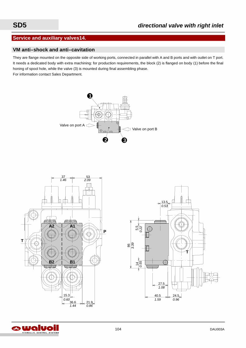
1
2 3
VM anti--shock and anti--cavitation
Service and auxiliary valves14.
They are flange mounted on the opposite side of working ports, connected in parallel with A and B ports and with outlet on T port.
It needs a dedicated body with extra machining: for production requirements, the block (2) is flanged on body (1) before the final
honing of spool hole, while the valve (3) is mounted during final assembling phase.
For information contact Sales Department.
Valve on port BValve on port A
27.5
40.5
14
86
13.5
24.5
5.5A2 A1
B2 B1
T
P
15.3
36.6 21.9
5337
T
1.46 2.09
0.60
1.44 0.86
0.22
3.39
0.55
1.08
1.59 0.96
0.53
SD5 directional valve with right inlet
104 DAU003A
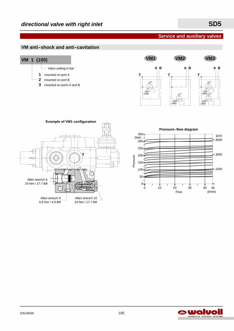
VM1 VM2 VM3
A B
T
A BA B
TT
1001450
1001450
1001450
1001450
0
50
100
150
200
250
300
350
0 10 20 30 40
Pressure--flow diagram
Flow
Pre
ssur
e(bar)
(l/min)45
(psi)4500
3000
1500
VM anti--shock and anti--cavitation
Service and auxiliary valves
Example of VM1 configuration
Allen wrench 1024 Nm / 17.7 lbft
Allen wrench 624 Nm / 17.7 lbft
T
Allen wrench 46.6 Nm / 4.9 lbft
Valve setting in bar
1 mounted on port A
2 mounted on port B
3 mounted on ports A and B
VM 1 (100)
directional valve with right inlet SD5
105DAU003A
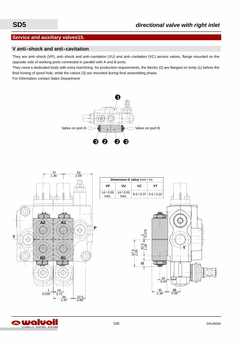
1
2
They are anti--shock (VP), anti--shock and anti--cavitation (VU) and anti--cavitation (VC) service valves, flange mounted on the
opposite side of working ports connected in parallel with A and B ports.
They need a dedicated body with extra machining: for production requirements, the blocks (2) are flanged on body (1) before the
final honing of spool hole, while the valves (3) are mounted during final assembling phase.
For information contact Sales Department
V anti--shock and anti--cavitation
Service and auxiliary valves15.
323
Valve on port BValve on port A57
.5
32.5
2
2535
16
D
T
18
36 22.5
5337
1
A2 A1
B2 B1
T
P
5.5 / 0.22
Dimension D value (mm / in)
VP VCVU VT
9.5 / 0.3714 / 0.55max.
14 / 0.55max.
1.46 2.09
0.891.42
0.710.039
2.26
1.28
0.07
9
1.3825
0.98
0.63
SD5 directional valve with right inlet
106 DAU003A
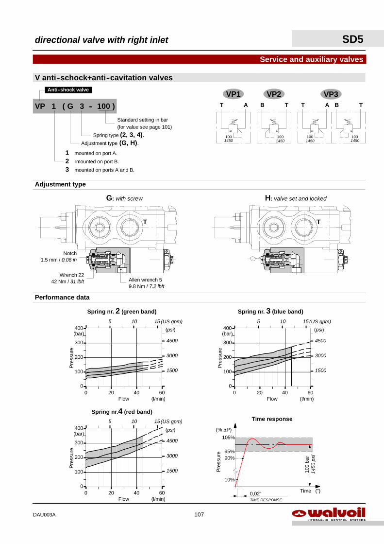
0
100
200
300
400
0 20 40 60
0
100
200
300
400
0 20 40 600
100
200
300
400
0 20 40 60
0,02”TIME RESPONSE
10%
100
bar90%
95%
105%
Pre
ssur
e
Time (”)
(% ∆P)
Time response
1450
psi
Spring nr.4 (red band)
Flow
Pre
ssur
e
(l/min)
(bar)(psi)
4500
3000
1500
Spring nr. 3 (blue band)
Flow
Pre
ssur
e
(l/min)
(bar)(psi)
4500
3000
1500
Spring nr. 2 (green band)
Flow
Pre
ssur
e
(l/min)
(bar)(psi)
4500
3000
1500
Performance data
5 10 15 (US gpm) 5 10 15 (US gpm)
5 10 15 (US gpm)
VP1 VP2T A
100
B T
100
T A
100
B T
100
VP3
1450 1450 1450 1450
VP 1 ( G 3 -- 100 )
Adjustment type (G, H).Spring type (2, 3, 4).
1 mounted on port A.
2 rmounted on port B.
3 mounted on ports A and B.
Standard setting in bar(for value see page 101)
Anti--shock valve
V anti--schock+anti--cavitation valves
Service and auxiliary valves
G: with screw H: valve set and locked
Adjustment type
T
Allen wrench 59.8 Nm / 7.2 lbft
Notch1.5 mm / 0.06 in
T
Wrench 2242 Nm / 31 lbft
directional valve with right inlet SD5
107DAU003A
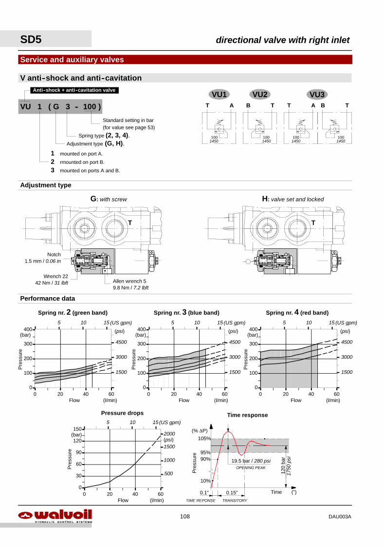
Pressure drops
0
30
60
90
120
150
0 20 40 60Flow
Pre
ssur
e
(l/min)
(bar)
0
100
200
300
400
0 20 40 60
Performance data
0
100
200
300
400
0 20 40 600
100
200
300
400
0 20 40 60Flow
Pre
ssur
e
(l/min)
(bar)
Flow
Pre
ssur
e
(l/min)
(bar)
Spring nr. 3 (blue band) Spring nr. 4 (red band)
Flow
Pre
ssur
e
(l/min)
(bar)
Spring nr. 2 (green band)
0.1”TIME REPONSE
10%
120
bar90%
95%
105%
Pre
ssur
e
Time (”)
(% ∆P)
0.15”TRANSITORY
19.5 bar / 280 psiOPENING PEAK
Time response
(psi)
4500
3000
1500
(psi)
4500
3000
1500
(psi)
4500
3000
1500
1500
1000
500
(psi)2000
1750
psi
5 10 15 (US gpm) 5 10 15 (US gpm) 5 10 15 (US gpm)
5 10 15 (US gpm)
VU1 VU2T A
100
B T
100
T A
100
B T
100
VU3
1450 145014501450
VU 1 ( G 3 -- 100 )
Adjustment type (G, H).Spring type (2, 3, 4).
1 mounted on port A.
2 rmounted on port B.
3 mounted on ports A and B.
Standard setting in bar(for value see page 53)
Anti--shock + anti--cavitation valve
V anti--shock and anti--cavitation
Service and auxiliary valves
G: with screw H: valve set and locked
Adjustment type
T T
Allen wrench 59.8 Nm / 7.2 lbft
Notch1.5 mm / 0.06 in
Wrench 2242 Nm / 31 lbft
SD5 directional valve with right inlet
108 DAU003A
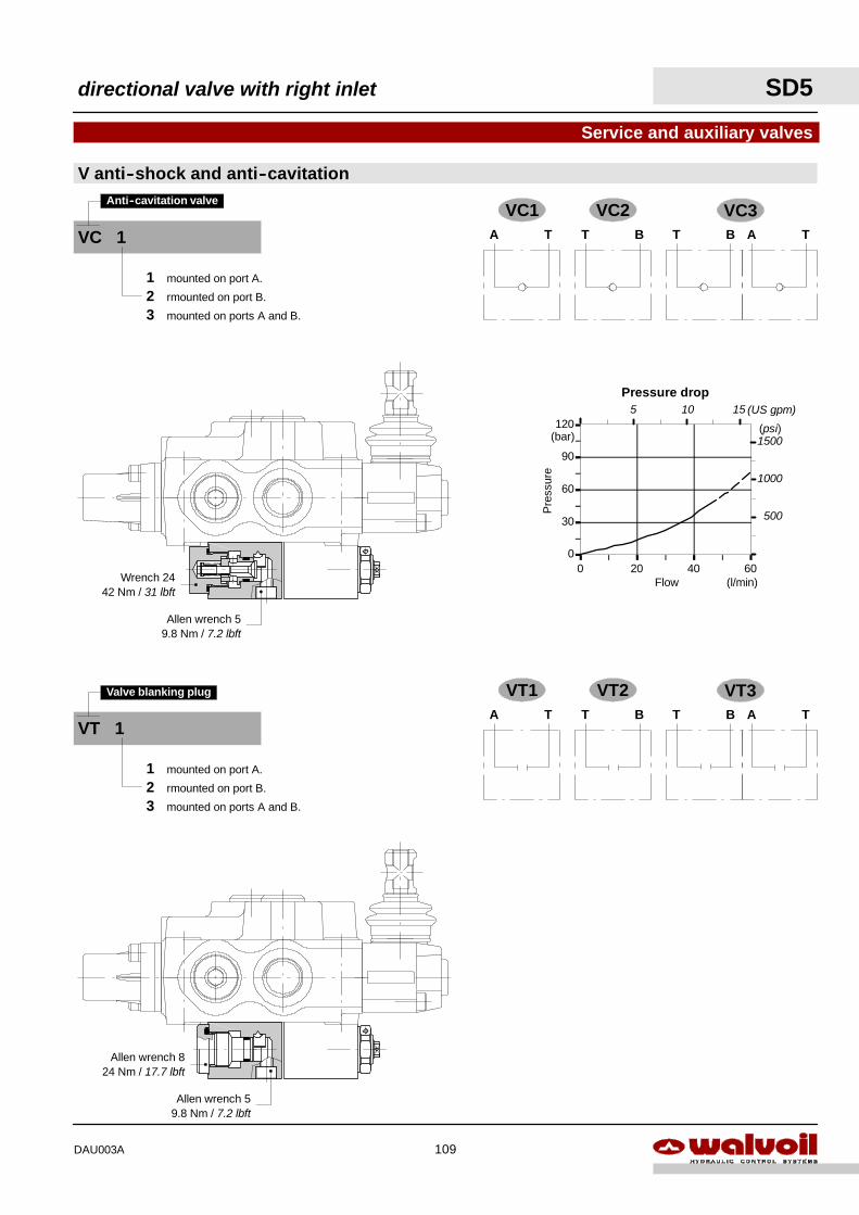
Pressure drop
0
30
60
90
120
0 20 40 60Flow
Pre
ssur
e
(l/min)
(bar) 1500
1000
500
(psi)
5 10 15 (US gpm)
VC 1
Anti--cavitation valve
1 mounted on port A.
2 rmounted on port B.
3 mounted on ports A and B.
V anti--shock and anti--cavitation
Service and auxiliary valves
VC1 VC2TA BT TABT
VC3
VT1 VT2TA BT TABT
VT3
Allen wrench 59.8 Nm / 7.2 lbft
Wrench 2442 Nm / 31 lbft
VT 1
Valve blanking plug
1 mounted on port A.
2 rmounted on port B.
3 mounted on ports A and B.
Allen wrench 59.8 Nm / 7.2 lbft
Allen wrench 824 Nm / 17.7 lbft
directional valve with right inlet SD5
109DAU003A
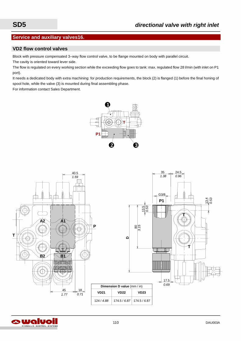
1
VD2 flow control valves
Service and auxiliary valves16.
Block with pressure compensated 3--way flow control valve, to be flange mounted on body with parallel circuit.
The cavity is oriented toward lever side.
The flow is regulated on every working section while the exceeding flow goes to tank: max. regulated flow 28 l/min (with inlet on P1
port).
It needs a dedicated body with extra machining: for production requirements, the block (2) is flanged (1) before the final honing of
spool hole, while the valve (3) is mounted during final assembling phase.
For information contact Sales Department.
45 18
40.5
17.5
35
D
24.5
80
G3/8
13.5
TA2 A1
B2 B1
T
P
13.4P1
T
T
P1
2 3
Dimension D value (mm / in)
VD21 VD23VD22
174.5 / 6.87174.5 / 6.87124 / 4.88
1.59
1.77 0.71
3.15
0.53
0.53
0.69
1.38 0.96
SD5 directional valve with right inlet
110 DAU003A
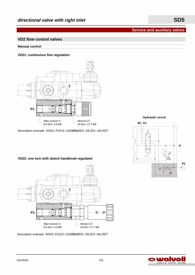
VD2 flow control valves
Service and auxiliary valves
Manual control
Description example: SD5/2--P(JG3--120)VD11/ED--18L/ED--18L/AET
Description example: SD5/2--P(JG3--120)VD12/ED--18L/ED--18L/AET
P
B1 A1
120
P1
VD21: continuous fine regulation
VD22: one turn with detent handknob regulated
Hydraulic circuit
C
R
P1
T
P1
T
Allen wrench 46.6 Nm / 4.9 lbft
Wrench 2724 Nm / 17.7 lbft
Wrench 2724 Nm / 17.7 lbft
Allen wrench 46.6 Nm / 4.9 lbft
1750
directional valve with right inlet SD5
111DAU003A
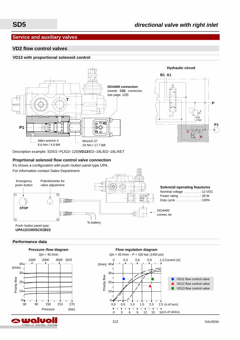
Solenoid operating feauturesNominal voltage : 12 VDC. . . . . . . . .Power rating : 28 W. . . . . . . . . . . .Duty cycle : 100%. . . . . . . . . . . . . .
VD2 flow control valves
Service and auxiliary valves
VD13 with proportional solenoid control
P
B1 A1
120
P1
Description example: SD5/2--P(JG3--120)VD13/ED--18L/ED--18L/AET
Proprtional solenoid flow control valve connection
STOP
To battery
ISO4400connec tor
Potentiometer forvalve adjustment
Emergencypush--button
Push--button panel type:UPA12/100/SC01B22
It’s shows a configuration with push--button panel type UPA.
For information contact Sales Department.
C
R
Hydraulic circuit
ISO4400 connection(needs C02 connector,see page. 129)
P1
T
Wrench 2724 Nm / 17.7 lbft
Allen wrench 46.6 Nm / 4.9 lbft
1750
0
10
20
30
40
30 90 150 210 270
0.3 0.6 0.9 1.2 Current (A)0
0
10
20
30
40
0.0 0.5 1.0 1.5 2.0 2.5
3 6 9 12 15 18
Flow regulation diagramQin = 45 l/min -- P = 100 bar (1450 psi)
Prio
rity
flow
(l/min)
(n.of clicks)
(n.of turn)
0
F J
Y
Performance data
Prio
rity
flow
(l/min)
Pressure (bar)
Pressure--flow diagramQin = 45 l/min
F
J
Y
VD11 flow control valveVD12 flow control valveVD13 flow control valve
(psi)1000 2000 3000
SD5 directional valve with right inlet
112 DAU003A
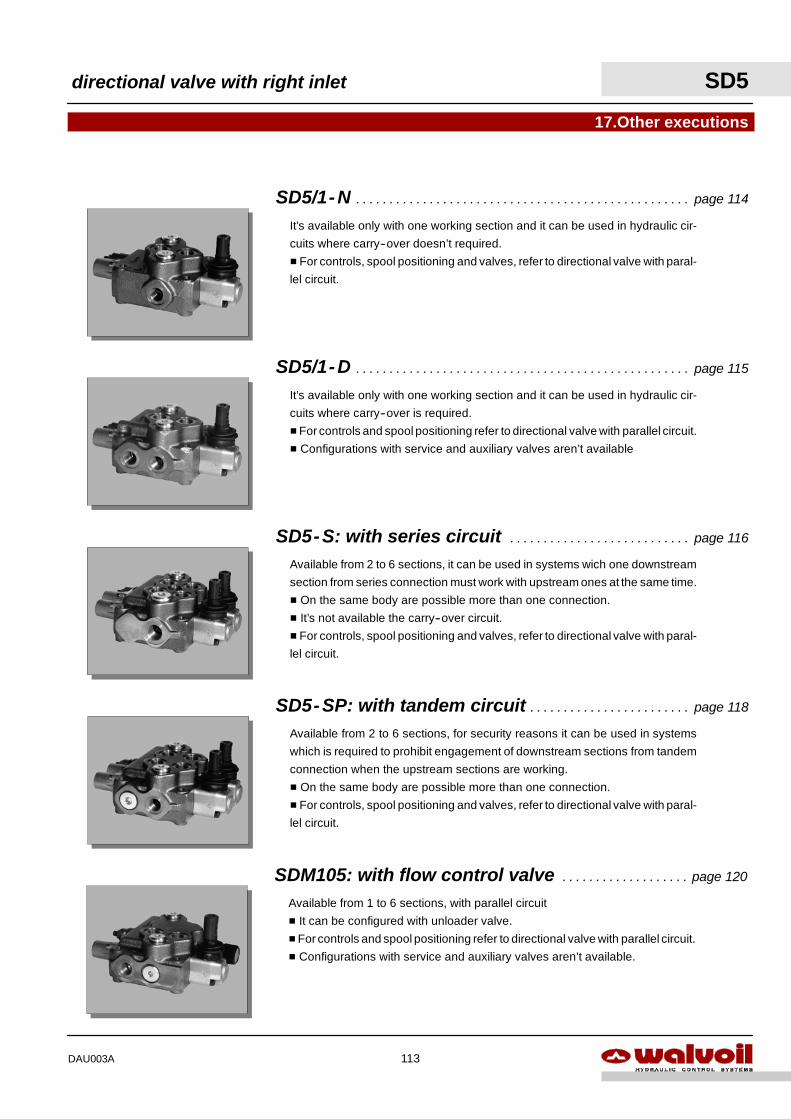
Available from 2 to 6 sections, it can be used in systems wich one downstream
section from series connection must work with upstream ones at the same time.
H On the same body are possible more than one connection.
H It’s not available the carry--over circuit.
H For controls, spool positioning and valves, refer to directional valve with paral-
lel circuit.
17.Other executions
It’s available only with one working section and it can be used in hydraulic cir-
cuits where carry--over is required.
HFor controls and spool positioning refer to directional valve with parallel circuit.
H Configurations with service and auxiliary valves aren’t available
It’s available only with one working section and it can be used in hydraulic cir-
cuits where carry--over doesn’t required.
H For controls, spool positioning and valves, refer to directional valve with paral-
lel circuit.
SD5-SP: with tandem circuit page 118. . . . . . . . . . . . . . . . . . . . . . . .
Available from 2 to 6 sections, for security reasons it can be used in systems
which is required to prohibit engagement of downstream sections from tandem
connection when the upstream sections are working.
H On the same body are possible more than one connection.
H For controls, spool positioning and valves, refer to directional valve with paral-
lel circuit.
SD5-S: with series circuit page 116. . . . . . . . . . . . . . . . . . . . . . . . . . .
SD5/1-D page 115. . . . . . . . . . . . . . . . . . . . . . . . . . . . . . . . . . . . . . . . . . . . . . . . . .
SD5/1-N page 114. . . . . . . . . . . . . . . . . . . . . . . . . . . . . . . . . . . . . . . . . . . . . . . . . .
SDM105: with flow control valve page 120. . . . . . . . . . . . . . . . . . .
Available from 1 to 6 sections, with parallel circuit
H It can be configured with unloader valve.
HFor controls and spool positioning refer to directional valve with parallel circuit.
H Configurations with service and auxiliary valves aren’t available.
directional valve with right inlet SD5
113DAU003A
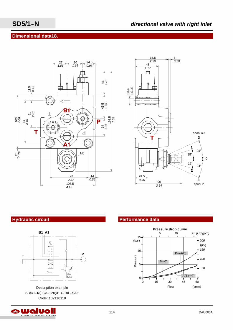
0
5
10
15
0 15 30 45 60
Flow
Pre
ssur
e
(l/min)
(bar)
P→T
P→A(B)
A(B)→T
Pressure drop curve
(psi)150
100
50
200
5 10 15 (US gpm)
Performance data
P
B1 A1
T
1201750
Dimensional data18.
Hydraulic circuit
Description example
SD5/1--N(JG3--120)/ED--18L--SAE
Code: 102110118
51
81
11.5
103
20
27 30 24.5
4645
.534
193.
5
1473
105.5
M8
63.5 5
45
8.5
24.5
90
15°
15°
1
2
0
24°
24°
spool out3
3spool in
1.06 1.18 0.96
1.81
45.5
1.79
1.35
7.62
4.15
2.87 0.55
0.79
4.06
3.19
2.01
0.45
0.33
2.50
1.77
0.20
0.96
3.54
SD5/1--N directional valve with right inlet
114 DAU003A
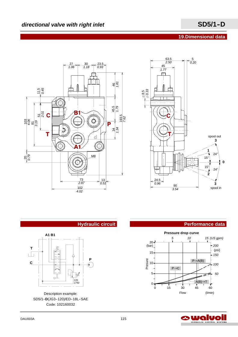
0
5
10
15
20
0 15 30 45 60
Flow
Pre
sure
(l/min)
(bar)
P→C
P→A(B)
A(B)→T
Pressure drop curve
(psi)
150
100
50
200
5 10 15 (US gpm)
Performance data
19.Dimensional data51
81
11.5
103
20
27 30 23.5
4645
.534
193.
5
1373
102
P
A1 B1
Description example:
SD5/1--D(JG3--120)/ED--18L--SAE
Code: 102160032
120
T
C
63.5 5
45
8.5
24.5
90
15°
15°
1
2
0
24°
24°
spool out3
3spool in
M8
Hydraulic circuit
1750
1.06 1.18 0.93
1.81
1.79
1.34
7.62
0.45
2.01
3.19
0.79
4.06
4.02
2.87 0.51 0.96
3.54
2.50
1.77
0.20
0.33
directional valve with right inlet SD5/1--D
115DAU003A
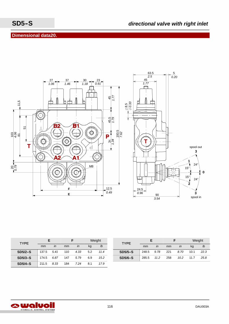
Dimensional data20.
3037
51
81
34
193.
5
103
45
12.5
11,5
23
45.5
27
20
F
E
63.5 5
45
8.5
24.5
90
15°
15°
1
2
0
24°
24°
spool out3
3spool in
M8
1.06 1.46 1.18 0.91
1.77
1.79
1.34
7.62
0.49
0.79
4.06
3.54
0.96
0.33
1.77
2.5 0.20
SD5--S directional valve with right inlet
116 DAU003A
TYPEE F Weight
TYPEE F Weight
TYPEmm in mm in kg lb
TYPEmm in mm in kg lb
SD5/2--S 137.5 5.41 110 4.33 5.2 11.4 SD5/5--S 248.5 9.78 221 8.70 10.1 22.3
SD5/3--S 174.5 6.87 147 5.79 6.9 15.2 SD5/6--S 285.5 11.2 258 10.2 11.7 25.8
SD5/4--S 211.5 8.33 184 7.24 8.1 17.9
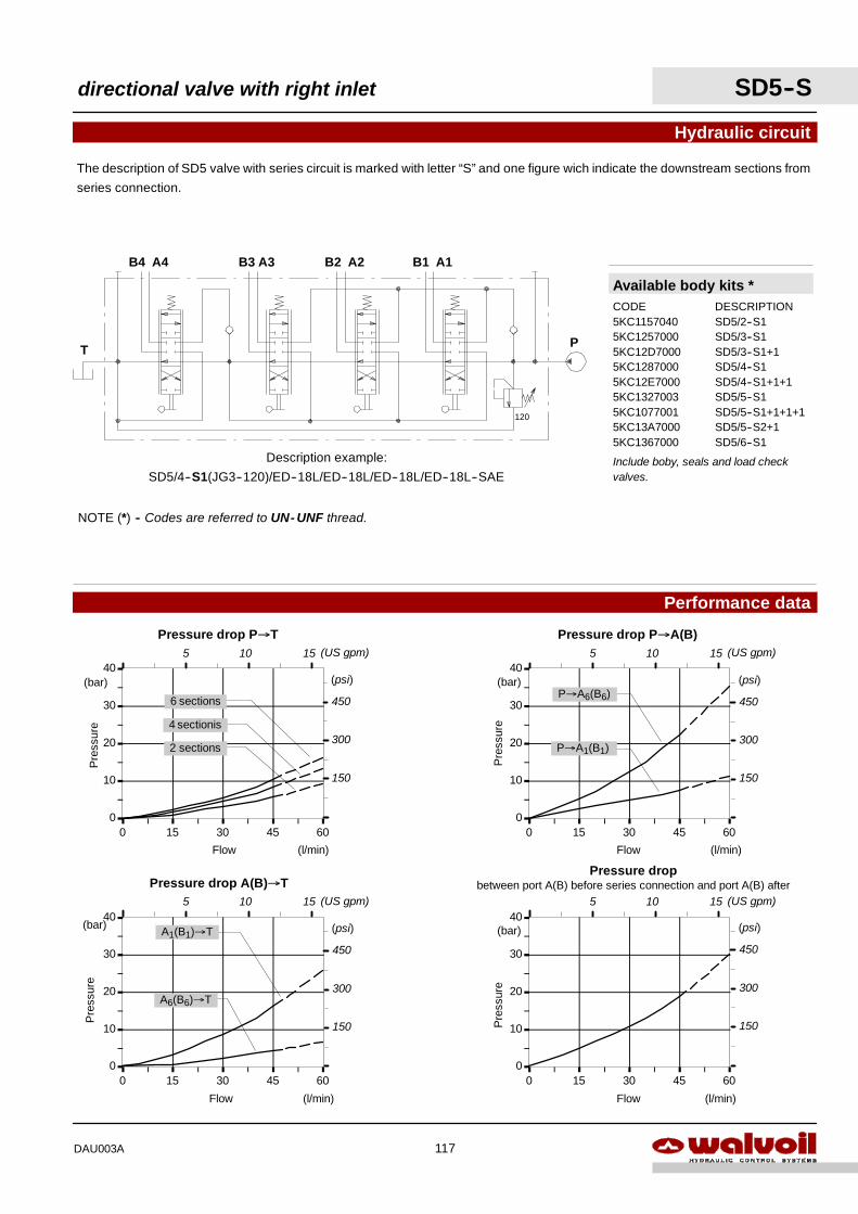
0
10
20
30
40
0 15 30 45 60
Flow
Pre
ssur
e
(l/min)
(bar)
Pressure dropbetween port A(B) before series connection and port A(B) after
(psi)
450
300
150
5 10 15 (US gpm)
0
10
20
30
40
0 15 30 45 60
A6(B6)→T
A1(B1)→T
Flow
Pre
ssur
e
(l/min)
(bar)
Pressure drop A(B)→T
(psi)
450
300
150
5 10 15 (US gpm)
0
10
20
30
40
0 15 30 45 60
P→A6(B6)
Flow
Pre
ssur
e
(l/min)
(bar)
Pressure drop P→A(B)
P→A1(B1)
(psi)
450
300
150
5 10 15 (US gpm)
0
10
20
30
40
0 15 30 45 60
Flow
Pre
ssur
e
(l/min)
(bar)
Pressure drop P→T
2 sections
4 sectionis
6 sections
(psi)
450
300
150
5 10 15 (US gpm)
NOTE (*) -- Codes are referred to UN- UNF thread.
Available body kits *CODE DESCRIPTION5KC1157040 SD5/2--S15KC1257000 SD5/3--S15KC12D7000 SD5/3--S1+15KC1287000 SD5/4--S15KC12E7000 SD5/4--S1+1+15KC1327003 SD5/5--S15KC1077001 SD5/5--S1+1+1+15KC13A7000 SD5/5--S2+15KC1367000 SD5/6--S1
Include boby, seals and load checkvalves.
Hydraulic circuit
The description of SD5 valve with series circuit is marked with letter “S” and one figure wich indicate the downstream sections from
series connection.
B3 A3B4 A4
T
Description example:
SD5/4--S1(JG3--120)/ED--18L/ED--18L/ED--18L/ED--18L--SAE
P
B1 A1B2 A2
120
Performance data
directional valve with right inlet SD5--S
117DAU003A
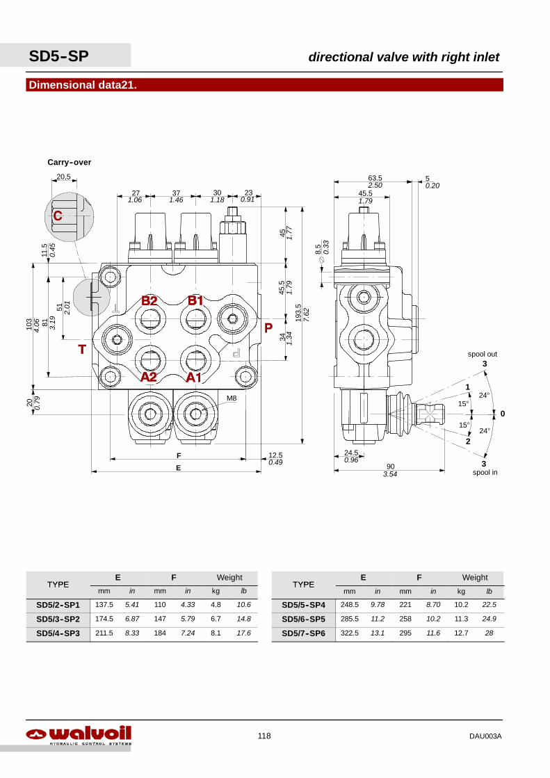
Dimensional data21.
3037
51
81
34
193.
5
103
45
12.5
11.5
23
45.5
27
20
F
E
20,5
Carry--over
90
24.5
45.5
63.5 5
8.5
15°
15°
1
2
0
24°
24°
spool out3
3spool in
M8
1.06 1.46 1.18 0.91
1.79
1.77
1.34
7.62
0.49
0.79
0.45
2.01
3.19
4.06
3.54
0.96
0.33
2.50
1.79
0.20
SD5--SP directional valve with right inlet
118 DAU003A
TYPEE F Weight
TYPEE F Weight
TYPEmm in mm in kg lb
TYPEmm in mm in kg lb
SD5/2--SP1 137.5 5.41 110 4.33 4.8 10.6 SD5/5--SP4 248.5 9.78 221 8.70 10.2 22.5
SD5/3--SP2 174.5 6.87 147 5.79 6.7 14.8 SD5/6--SP5 285.5 11.2 258 10.2 11.3 24.9
SD5/4--SP3 211.5 8.33 184 7.24 8.1 17.6 SD5/7--SP6 322.5 13.1 295 11.6 12.7 28
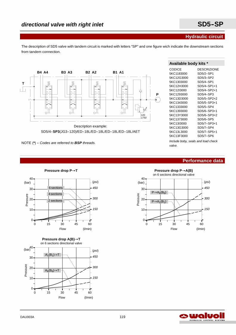
Hydraulic circuit
The description of SD5 valve with tandem circuit is marked with letters “SP” and one figure wich indicate the downstream sections
from tandem connection.
B3 A3B4 A4
Description example:
SD5/4--SP3(JG3--120)/ED--18L/ED--18L/ED--18L/ED--18L/AET
P
B1 A1B2 A2
120
Available body kits *CODICE DESCRIZIONE5KC1183000 SD5/2--SP15KC12G3000 SD5/3--SP25KC1303000 SD5/4--SP15KC12H3000 SD5/4--SP1+15KC12I3000 SD5/4--SP2+15KC1293000 SD5/4--SP35KC13D3000 SD5/5--SP2+25KC1343000 SD5/5--SP3+15KC1333000 SD5/5--SP45KC1393000 SD5/6--SP3+15KC13Y3000 SD5/6--SP3+25KC1373000 SD5/6--SP55KC13I3000 SD5/7--SP3+15KC13G3000 SD5/7--SP45KC13L3000 SD5/7--SP5+15KC13F3000 SD5/7--SP6
Include boby, seals and load checkvalve.
T
NOTE (*) -- Codes are referred to BSP threads.
0
10
20
30
40
0 15 30 45 60
0
10
20
30
40
0 15 30 45 60
A6(B6)→T
A1(B1)→T
Flow
Pre
ssur
e
(l/min)
(bar)
P→A6(B6)
Flow
Pre
ssur
e
(l/min)
(bar)
0
10
20
30
40
0 15 30 45 60
Flow
Pre
ssur
e
(l/min)
(bar)
Pressure drop P→T Pressure drop P→A(B)on 6 sections directional valve
Pressure drop A(B)→Ton 6 sections directional valve
P→A1(B1)
6 sections
4 sections
(psi)
450
300
150
2 sections
(psi)
450
300
150
(psi)
450
300
150
Performance data
1750
directional valve with right inlet SD5--SP
119DAU003A
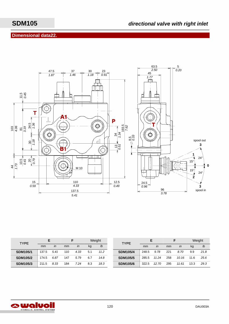
Dimensional data22.
15 110
137.5
47.5 37 30 23
3034
.5
10.5
81103
1334
20
44
11.5
193.
5
12.5
45
63.5 5
24.5
96
M 10
15°
15°
1
2
0
24°
24°
spool out3
3spool in
8.5
1.87 1.46 1.18 0.91
1.34
0.51
7.62
0.49
5.41
4.330.59
0.41
0.79
1.18
1.36
3.19
0.45
4.06
1.73
2.50
1.77
0.33
0.96
3.78
0.20
SDM105 directional valve with right inlet
120 DAU003A
TYPEE F Weight
TYPEE F Weight
TYPEmm in mm in kg lb
TYPEmm in mm in kg lb
SDM105/1 137.5 5.41 110 4.33 5.1 11.2 SDM105/4 248.5 9.78 221 8.70 9.9 21.8
SDM105/2 174.5 6.87 147 5.79 6.7 14.8 SDM105/5 285.5 11.24 258 10.16 11.6 25.6
SDM105/3 211.5 8.33 184 7.24 8.3 18.3 SDM105/6 322.5 12.70 295 11.61 13.3 29.3
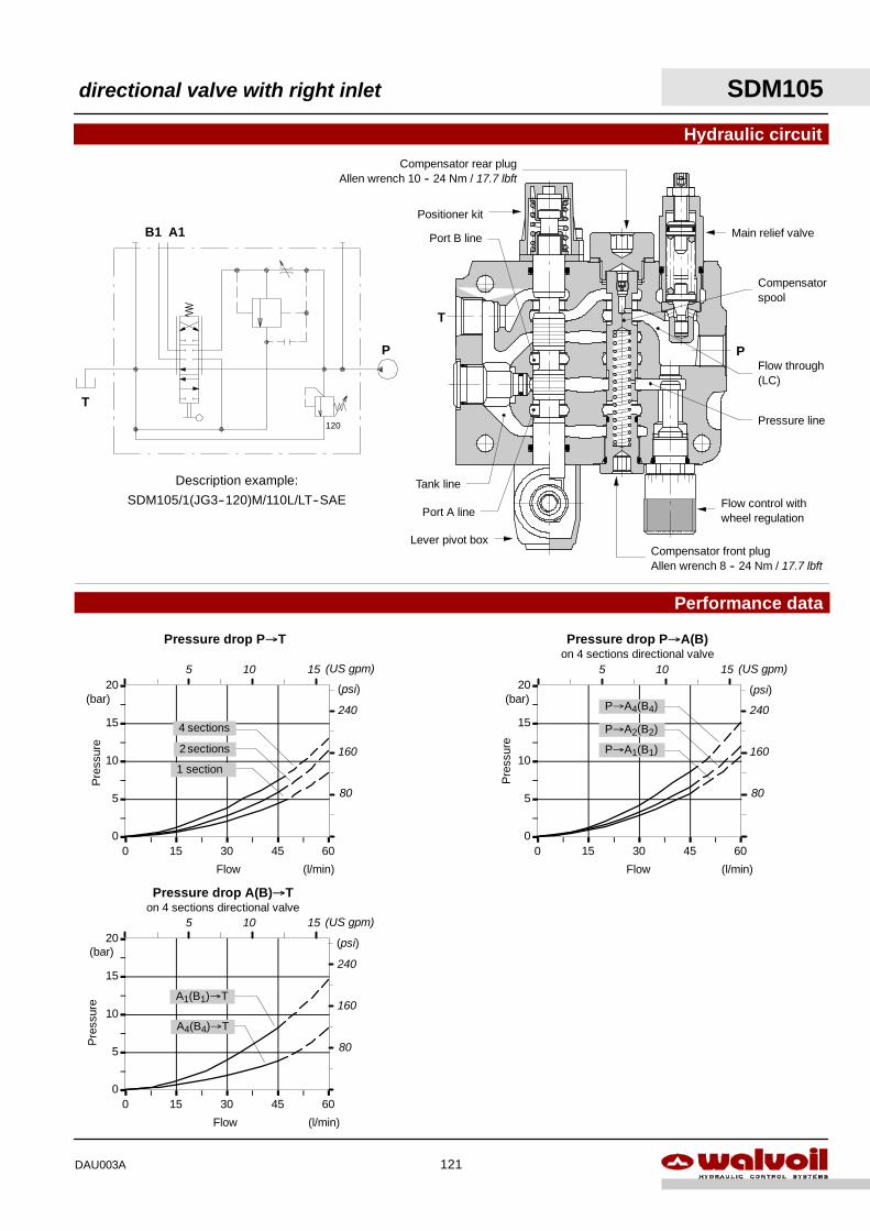
Hydraulic circuit
P
B1 A1
120
T
0
5
10
15
20
0 15 30 45 60
0
5
10
15
20
0 15 30 45 60
A4(B4)→T
A1(B1)→T
Flow
Pre
ssur
e
(l/min)
(bar)
Flow
Pre
ssur
e
(l/min)
(bar)
0
5
10
15
20
0 15 30 45 60
Flow
Pre
ssur
e
(l/min)
(bar)
Pressure drop P→T Pressure drop P→A(B)on 4 sections directional valve
Pressure drop A(B)→Ton 4 sections directional valve
P→A1(B1)
4 sections
2 sections
(psi)
1 section
(psi)
240
160
80
Description example:
SDM105/1(JG3--120)M/110L/LT--SAE
Performance data
Positioner kit
Main relief valve
Flow control withwheel regulation
Compensatorspool
Lever pivot box
Flow through(LC)
Pressure line
Tank line
P
T
Port A line
Port B line
P→A2(B2)
P→A4(B4)240
160
80
(psi)
240
160
80
Compensator front plugAllen wrench 8 -- 24 Nm / 17.7 lbft
Compensator rear plugAllen wrench 10 -- 24 Nm / 17.7 lbft
5 10 15 (US gpm)
5 10 15 (US gpm)
5 10 15 (US gpm)
directional valve with right inlet SDM105
121DAU003A
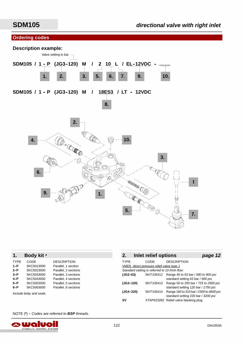
SDM105 directional valve with right inlet
122 DAU003A
2. Inlet relief options page 121. Body kit *
Ordering codes
2.
2.
SDM105 / 1 -- P (JG3--120) M / 2 10 L / EL--12VDC -- ........
TYPE CODE DESCRIPTION1--P 5KC5013000 Parallel, 1 section2--P 5KC5023000 Parallel, 2 sections3--P 5KC5033000 Parallel, 3 sections4--P 5KC5043000 Parallel, 4 sections5--P 5KC5053000 Parallel, 5 sections6--P 5KC5063000 Parallel, 6 sections
TYPE CODE DESCRIPTIONVMD5 direct pressure relief valve type JStandard setting is referred to 10 l/min flow.(JG2--63) 5KIT105412 Range 40 to 63 bar / 580 to 900 psi
standard setting 63 bar / 900 psi(JG3--120) 5KIT105413 Range 50 to 200 bar / 725 to 2900 psi
standard setting 120 bar / 1750 psi(JG4--220) 5KIT105414 Range 160 to 315 bar / 2300 to 4600 psi
standard setting 220 bar / 3200 psiSV XTAP623282 Relief valve blanking plug
3. 7.
Include boby and seals.
1.
Description example:
I
7.
3.
10.
6.
1. 5.
NOTE (*) -- Codes are referred to BSP threads.
9.
9.
5.
Valve setting in bar
6. 10.
SDM105 / 1 -- P (JG3--120) M / 18ES3 / LT -- 12VDC
8.
4.
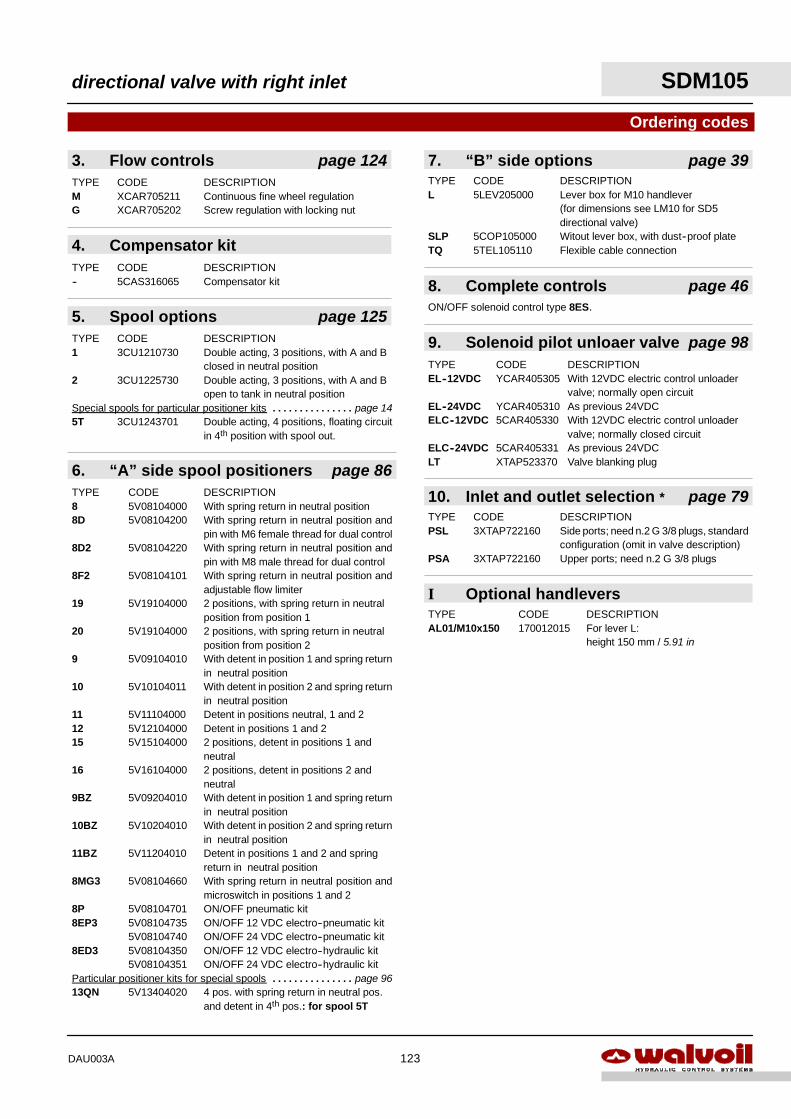
directional valve with right inlet SDM105
123DAU003A
9. Solenoid pilot unloaer valve page 98
I Optional handlevers
Ordering codes
TYPE CODE DESCRIPTIONAL01/M10x150 170012015 For lever L:
height 150 mm / 5.91 in
8. Complete controls page 46ON/OFF solenoid control type 8ES.
7. “B” side options page 39TYPE CODE DESCRIPTIONL 5LEV205000 Lever box for M10 handlever
(for dimensions see LM10 for SD5directional valve)
SLP 5COP105000 Witout lever box, with dust--proof plateTQ 5TEL105110 Flexible cable connection
TYPE CODE DESCRIPTIONEL--12VDC YCAR405305 With 12VDC electric control unloader
valve; normally open circuitEL--24VDC YCAR405310 As previous 24VDCELC--12VDC 5CAR405330 With 12VDC electric control unloader
valve; normally closed circuitELC--24VDC 5CAR405331 As previous 24VDCLT XTAP523370 Valve blanking plug
5. Spool options page 125TYPE CODE DESCRIPTION1 3CU1210730 Double acting, 3 positions, with A and B
closed in neutral position2 3CU1225730 Double acting, 3 positions, with A and B
open to tank in neutral positionSpecial spools for particular positioner kits page 14. . . . . . . . . . . . . . .5T 3CU1243701 Double acting, 4 positions, floating circuit
in 4th position with spool out.
3. Flow controls page 124TYPE CODE DESCRIPTIONM XCAR705211 Continuous fine wheel regulationG XCAR705202 Screw regulation with locking nut
10. Inlet and outlet selection * page 79TYPE CODE DESCRIPTIONPSL 3XTAP722160 Side ports; need n.2 G 3/8 plugs, standard
configuration (omit in valve description)PSA 3XTAP722160 Upper ports; need n.2 G 3/8 plugs
6. “A” side spool positioners page 86TYPE CODE DESCRIPTION8 5V08104000 With spring return in neutral position8D 5V08104200 With spring return in neutral position and
pin with M6 female thread for dual control8D2 5V08104220 With spring return in neutral position and
pin with M8 male thread for dual control8F2 5V08104101 With spring return in neutral position and
adjustable flow limiter19 5V19104000 2 positions, with spring return in neutral
position from position 120 5V19104000 2 positions, with spring return in neutral
position from position 29 5V09104010 With detent in position 1 and spring return
in neutral position10 5V10104011 With detent in position 2 and spring return
in neutral position11 5V11104000 Detent in positions neutral, 1 and 212 5V12104000 Detent in positions 1 and 215 5V15104000 2 positions, detent in positions 1 and
neutral16 5V16104000 2 positions, detent in positions 2 and
neutral9BZ 5V09204010 With detent in position 1 and spring return
in neutral position10BZ 5V10204010 With detent in position 2 and spring return
in neutral position11BZ 5V11204010 Detent in positions 1 and 2 and spring
return in neutral position8MG3 5V08104660 With spring return in neutral position and
microswitch in positions 1 and 28P 5V08104701 ON/OFF pneumatic kit8EP3 5V08104735 ON/OFF 12 VDC electro--pneumatic kit
5V08104740 ON/OFF 24 VDC electro--pneumatic kit8ED3 5V08104350 ON/OFF 12 VDC electro--hydraulic kit
5V08104351 ON/OFF 24 VDC electro--hydraulic kitParticular positioner kits for special spools page 96. . . . . . . . . . . . . . .13QN 5V13404020 4 pos. with spring return in neutral pos.
and detent in 4th pos.: for spool 5T
4. Compensator kitTYPE CODE DESCRIPTION-- 5CAS316065 Compensator kit
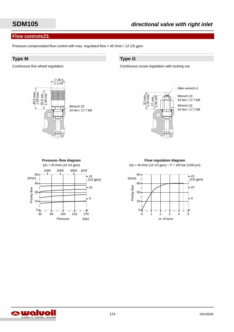
0
15
30
45
60
0 1 2 3 4 50
15
30
45
60
30 90 150 210 270
Flow regulation diagramQin = 45 l/min (12 US gpm) -- P = 100 bar (1450 psi)
Prio
rity
flow
(l/min)
Prio
rity
flow
(l/min)
Pressure (bar)
Pressure--flow diagramQin = 45 l/min (12 US gpm)
(psi)1000 2000 3000
Type M
Flow controls23.
Continuous fine wheel regulation
Type GContinuous screw regulation with locking nut.
35.5
min
.
40.5
max
.
∅ 26.5
Wrench 2224 Nm / 17.7 lbft
27m
in.
32m
ax.
Wrench 2224 Nm / 17.7 lbft
Wrench 1324 Nm / 17.7 lbft
Allen wrench 4
Pressure compensated flow control with max. regulated flow = 45 l/min / 12 US gpm.
∅ 1.04
1.40
min
.
1.59
max
.
1.26
max
.
1.06
min
.
nr. of turns
(US gpm)
5
10
15(US gpm)
5
10
15
SDM105 directional valve with right inlet
124 DAU003A
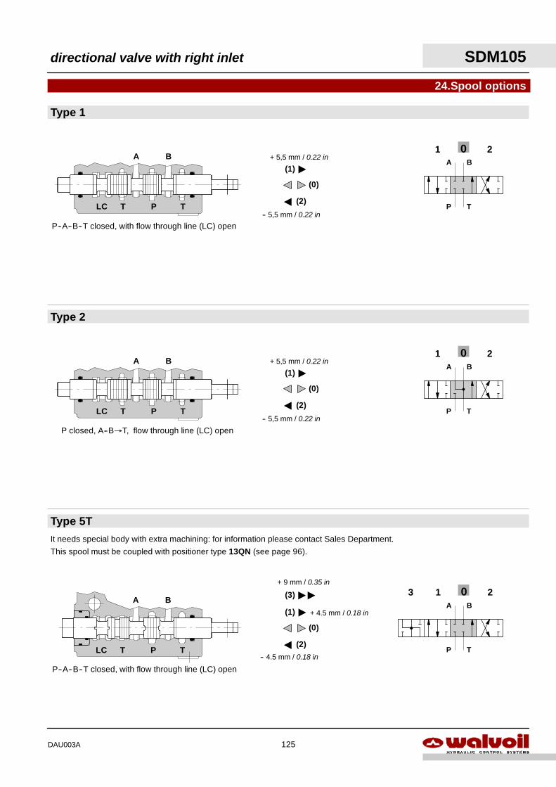
013 2A B
P T
Type 5T
Type 2
Type 1
24.Spool options
P--A--B--T closed, with flow through line (LC) open
P--A--B--T closed, with flow through line (LC) open
BA
TPLC T
201A B
P T
P closed, A--B→T, flow through line (LC) open
BA
TPLC T
201A B
P T
BA
TPLC TA
""
" + 4.5 mm / 0.18 in
+ 9 mm / 0.35 in
(0)
(1)
(2)
(3)
It needs special body with extra machining: for information please contact Sales Department.
This spool must be coupled with positioner type 13QN (see page 96).
A
-- 5,5 mm / 0.22 in
"
+ 5,5 mm / 0.22 in
(0)
(1)
(2)
A
-- 5,5 mm / 0.22 in
"
+ 5,5 mm / 0.22 in
(0)
(1)
(2)
-- 4.5 mm / 0.18 in
directional valve with right inlet SDM105
125DAU003A
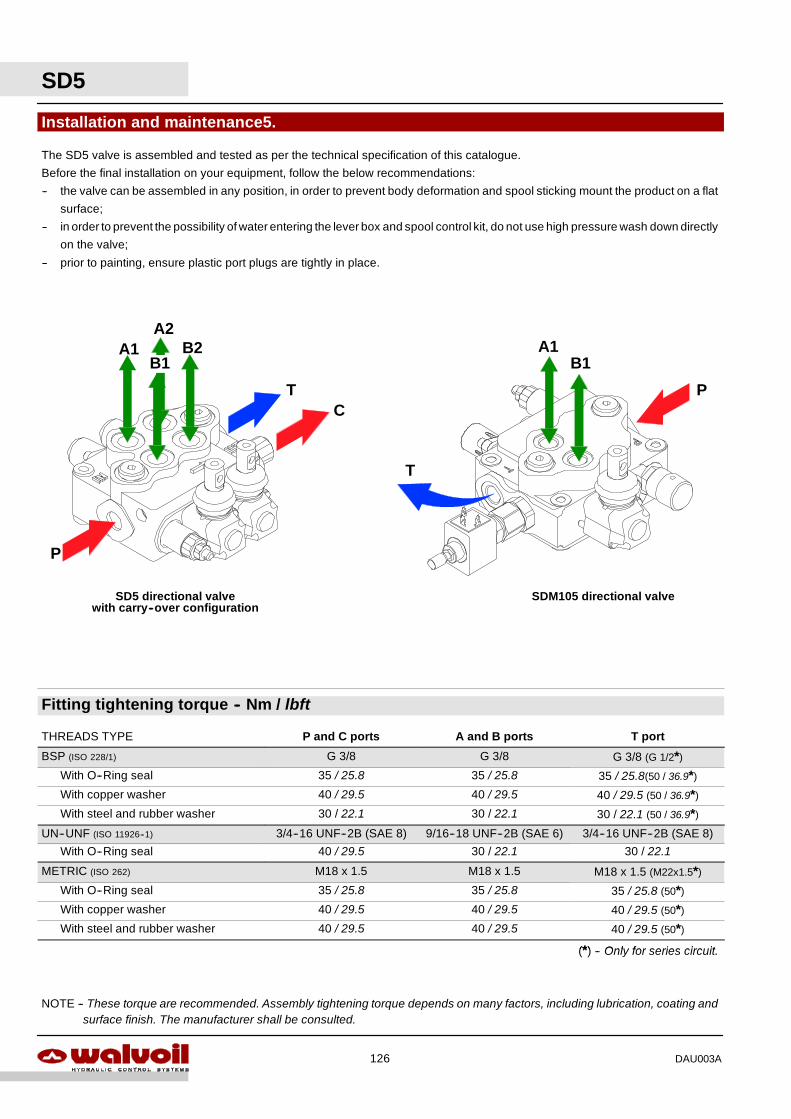
SD5
126 DAU003A
Fitting tightening torque -- Nm / lbft
THREADS TYPE P and C ports A and B ports T port
BSP (ISO 228/1) G 3/8 G 3/8 G 3/8 (G 1/2*)
With O--Ring seal 35 / 25.8 35 / 25.8 35 / 25.8(50 / 36.9*)
With copper washer 40 / 29.5 40 / 29.5 40 / 29.5 (50 / 36.9*)
With steel and rubber washer 30 / 22.1 30 / 22.1 30 / 22.1 (50 / 36.9*)
UN--UNF (ISO 11926--1) 3/4--16 UNF--2B (SAE 8) 9/16--18 UNF--2B (SAE 6) 3/4--16 UNF--2B (SAE 8)
With O--Ring seal 40 / 29.5 30 / 22.1 30 / 22.1
METRIC (ISO 262) M18 x 1.5 M18 x 1.5 M18 x 1.5 (M22x1.5*)
With O--Ring seal 35 / 25.8 35 / 25.8 35 / 25.8 (50*)
With copper washer 40 / 29.5 40 / 29.5 40 / 29.5 (50*)
With steel and rubber washer 40 / 29.5 40 / 29.5 40 / 29.5 (50*)
(*) Only for series circuit(*) -- Only for series circuit.
Installation and maintenance5.
A2
P
TC
A1B1
B2
SD5 directional valve
The SD5 valve is assembled and tested as per the technical specification of this catalogue.
Before the final installation on your equipment, follow the below recommendations:
-- the valve can be assembled in any position, in order to prevent body deformation and spool sticking mount the product on a flat
surface;
-- in order to prevent the possibility of water entering the lever box and spool control kit, do not use high pressure wash down directly
on the valve;
-- prior to painting, ensure plastic port plugs are tightly in place.
NOTE -- These torque are recommended. Assembly tightening torque depends on many factors, including lubrication, coating andsurface finish. The manufacturer shall be consulted.
A1B1
P
T
with carry--over configurationSDM105 directional valve
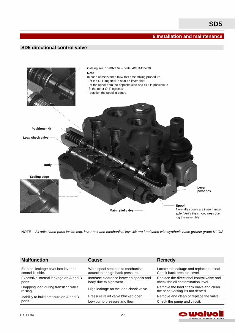
6.Installation and maintenance
NOTE -- All articulated parts inside cap, lever box and mechanical joystick are lubricated with synthetic base grease grade NLGI2
Body
Positioner kit
O--Ring seal 15.88x2.62 -- code: 4GUA115926
NoteIn case of assistance follw this assembling procedure-- fit the O--Rimg seal in seat on lever side;-- fit the spool from the opposite side and till it is possible tofit the other O--Ring seal;
-- position the spool in centre.
Sealing edge
Spool
Load check valve
Normally spools are interchange-able. Verify the smoothness dur-ing the assembly
Main relief valve
Leverpivot box
SD5 directional control valve
SD5
127DAU003A
Malfunction Cause Remedy
External leakage pivot box lever orcontrol kit side.
Worn spool seal due to mechanicalactuation or high back pressure.
Locate the leakage and replace the seal.Check back pressure level.
Excessive internal leakage on A and Bports.
Increase clearance between spools andbody due to high wear.
Replace the directional control valve andcheck the oil contamination level.
Dropping load during transition whileraising High leakage on the load check valve. Remove the load check valve and clean
the seat, verifing it’s not dented.
Inability to build pressure on A and B Pressure relief valve blocked open. Remove and clean or replace the valve.Inability to build pressure on A and Bports. Low pump pressure and flow. Check the pump and circuit.
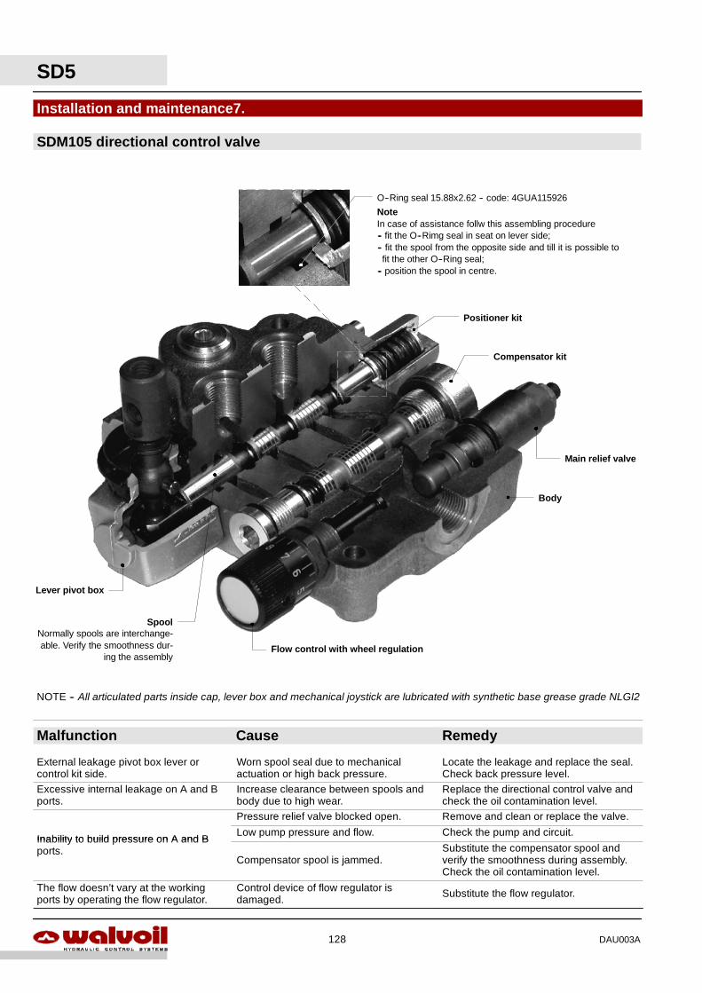
Installation and maintenance7.
NOTE -- All articulated parts inside cap, lever box and mechanical joystick are lubricated with synthetic base grease grade NLGI2
SDM105 directional control valve
Lever pivot box
Positioner kit
Main relief valve
Flow control with wheel regulation
Compensator kit
SpoolNormally spools are interchange-able. Verify the smoothness dur-
ing the assembly
Body
O--Ring seal 15.88x2.62 -- code: 4GUA115926
NoteIn case of assistance follw this assembling procedure-- fit the O--Rimg seal in seat on lever side;-- fit the spool from the opposite side and till it is possible tofit the other O--Ring seal;
-- position the spool in centre.
SD5
128 DAU003A
Malfunction Cause Remedy
External leakage pivot box lever orcontrol kit side.
Worn spool seal due to mechanicalactuation or high back pressure.
Locate the leakage and replace the seal.Check back pressure level.
Excessive internal leakage on A and Bports.
Increase clearance between spools andbody due to high wear.
Replace the directional control valve andcheck the oil contamination level.
Pressure relief valve blocked open. Remove and clean or replace the valve.
Inability to build pressure on A and BLow pump pressure and flow. Check the pump and circuit.
Inability to build pressure on A and Bports.
Compensator spool is jammed.Substitute the compensator spool andverify the smoothness during assembly.Check the oil contamination level.
The flow doesn’t vary at the workingports by operating the flow regulator.
Control device of flow regulator isdamaged. Substitute the flow regulator.
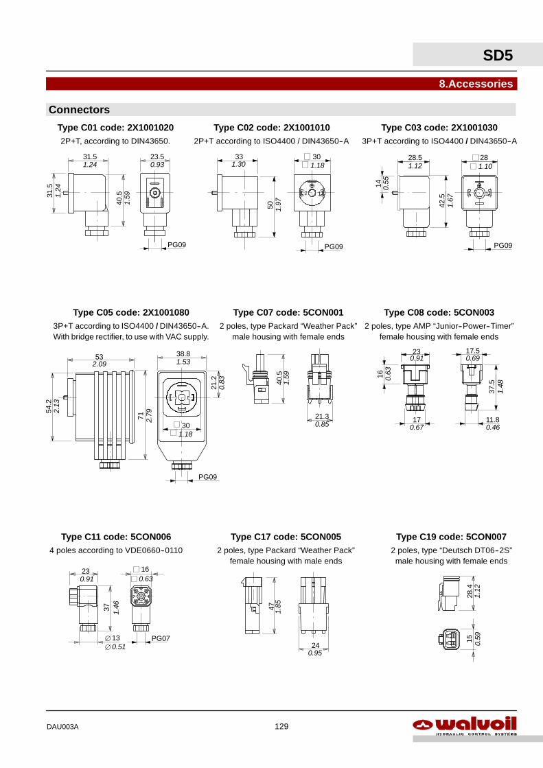
47
8.Accessories
Connectors
2 poles, type Packard “Weather Pack”female housing with male ends
Type C17 code: 5CON005
24
2 poles, type AMP “Junior--Power--Timer”female housing with female ends
Type C08 code: 5CON003
37.5
11.817
16
23 17.5
0
28.4
15
2 poles, type “Deutsch DT06--2S”male housing with female ends
Type C19 code: 5CON007
23.5
40.531
.5
31.5
2P+T, according to DIN43650.
Type C01 code: 2X1001020
PG09
1.24
1.24
1.59
0.93
50
33
2P+T according to ISO4400 / DIN43650--A
12
PG09
30
Type C02 code: 2X1001010
1.97
1.30 1.18
3P+T according to ISO4400 / DIN43650--A
42.5
28.5
14
28
1
PG09
Type C03 code: 2X1001030
0.55
1.12
1.67
1.10
53
71
54.2
38.8
21.2
3P+T according to ISO4400 / DIN43650--A.With bridge rectifier, to use with VAC supply.
Type C05 code: 2X1001080
PG09
2.13
2.09
2.79
1.53
0.83 40
.5
21.3
2 poles, type Packard “Weather Pack”male housing with female ends
Type C07 code: 5CON001
1.59
0.85
23
37
4 poles according to VDE0660--0110
Type C11 code: 5CON006
13∅
16
PG070.51∅
1.46
0.91 0.63
1.85
0.95
1.12
0.59
301.18
0.63
0.91
0.67
0.69
1.48
0.46
SD5
129DAU003A
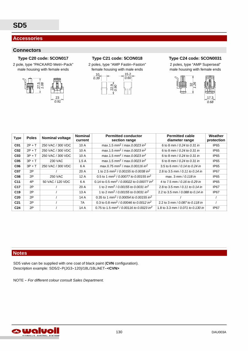
SD5
130 DAU003A
Type Poles Nominal voltage Nominalcurrent
Permitted conductorsection range
Permitted cablediameter range
Weatherprotection
C01 2P + T 250 VAC / 300 VDC 10 A max.1.5 mm2 / max.0.0023 in2 6 to 8 mm / 0.24 to 0.31 in IP65
C02 2P + T 250 VAC / 300 VDC 10 A max.1.5 mm2 / max.0.0023 in2 6 to 8 mm / 0.24 to 0.31 in IP65
C03 3P + T 250 VAC / 300 VDC 10 A max.1.5 mm2 / max.0.0023 in2 6 to 8 mm / 0.24 to 0.31 in IP65
C05 3P + T 230 VAC 1.5 A max.1.5 mm2 / max.0.0023 in2 6 to 8 mm / 0.24 to 0.31 in IP65
C06 3P + T 250 VAC / 300 VDC 6 A max.0.75 mm2 / max.0.00116 in2 3.5 to 6 mm / 0.14 to 0.24 in IP65
C07 2P / 20 A 1 to 2.5 mm2 / 0.00155 to 0.0038 in2 2.8 to 3.5 mm / 0.11 to 0.14 in IP67
C08 2P 250 VAC 12 A 0.5 to 1 mm2 / 0.00077 to 0.00155 in2 max. 3 mm / 0.118 in IP65
C11 4P 50 VAC / 120 VDC 6 A 0.14 to 0.5 mm2 / 0.00022 to 0.00077 in2 4 to 7.5 mm / 0.16 to 0.29 in IP65
C17 2P / 20 A 1 to 2 mm2 / 0.00155 to 0.0031 in2 2.8 to 3.5 mm / 0.11 to 0.14 in IP67
C19 2P / 13 A 1 to 2 mm2 / 0.00155 to 0.0031 in2 2.2 to 3.5 mm / 0.088 to 0.14 in IP67
C20 2P / 14 A 0.35 to 1 mm2 / 0.00054 to 0.00155 in2 / /
C21 2P / 7A 0.3 to 0.8 mm2 / 0.00046 to 0.0012 in2 2.2 to 3 mm / 0.087 to 0.118 in /
C24 2P / 14 A 0.75 to 1.5 mm2 / 0.00116 to 0.0023 in2 1.8 to 3.3 mm / 0.071 to 0.130 in IP67
Accessories27
.5
23
2 pole, type “PACKARD Metri--Pack”male housing with female ends
Type C20 code: 5CON017
32
17.3
2 poles, type “AMP Superseal”male housing with female ends
Type C24 code: 5CON0031
22.9
15.2
2 poles, type “AMP Fastin--Faston”female housing with male ends
Type C21 code: 5CON018
10
Connectors
Notes
SD5 valve can be supplied with one coat of black paint (CVN configuration).Description example: SD5/2--P(JG3--120)/18L/18L/AET--<CVN>
NOTE -- For different colour consult Sales Department.
1.08
0.91
0.90
0.39 0.60
1.26
0.68

SD5
131DAU003A

WALVOIL S.P.A.
42100 REGGIO EMILIA • ITALY • VIA ADIGE, 13/DTEL. +39.0522.932411 • FAX +39.0522.300984
E--MAIL: [email protected] • HTTP: //WWW.WALVOIL.COM
SERVIZIO COMMERCIALE
TEL. +39.0522.932555 • FAX +39.0522.932455
D1409808IDAU003E