Embed Size (px)
Citation preview

PDL 200A/PDL 234 SERIES MULTIFUNCTION ELECTRICAL TESTERS
Tests no-trip loop, socket, mains voltage & polarity
PDLSERIES
U S E R M A N U A L 0 6 / 0 6
2
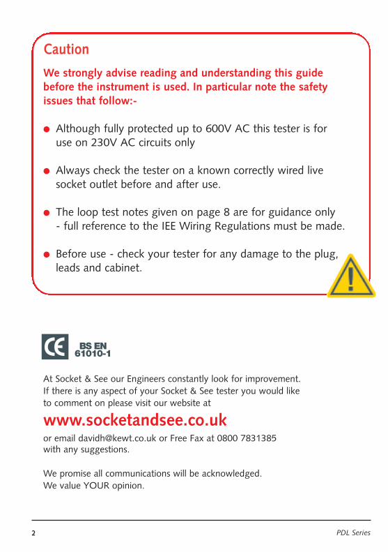
Caution
We strongly advise reading and understanding this guidebefore the instrument is used. In particular note the safetyissues that follow:-
l Although fully protected up to 600V AC this tester is for use on 230V AC circuits only
l Always check the tester on a known correctly wired live socket outlet before and after use.
l The loop test notes given on page 8 are for guidance only - full reference to the IEE Wiring Regulations must be made.
l Before use - check your tester for any damage to the plug,leads and cabinet.
At Socket & See our Engineers constantly look for improvement. If there is any aspect of your Socket & See tester you would like to comment on please visit our website at
www.socketandsee.co.ukor email [email protected] or Free Fax at 0800 7831385 with any suggestions.
We promise all communications will be acknowledged. We value YOUR opinion.
BS EN61010-1
PDL Series
3
Operation overview
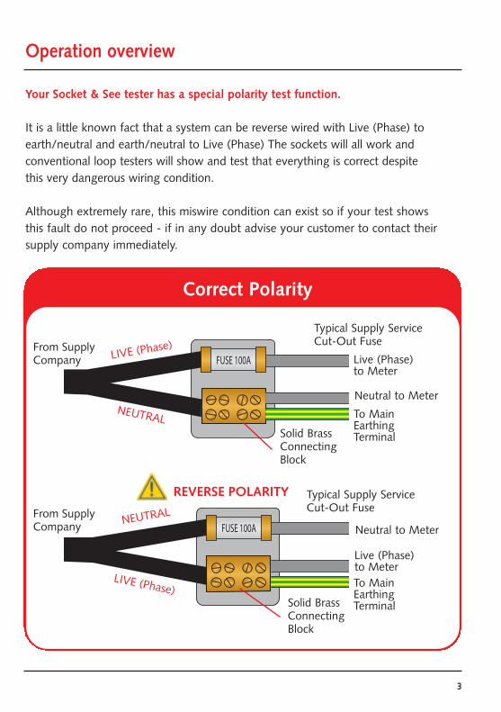
Your Socket & See tester has a special polarity test function.
It is a little known fact that a system can be reverse wired with Live (Phase) toearth/neutral and earth/neutral to Live (Phase) The sockets will all work and conventional loop testers will show and test that everything is correct despitethis very dangerous wiring condition.
Although extremely rare, this miswire condition can exist so if your test showsthis fault do not proceed - if in any doubt advise your customer to contact theirsupply company immediately.
FUSE 100A
FUSE 100A
From SupplyCompany Live (Phase)
to Meter
Neutral to Meter
To MainEarthingTerminal
Neutral to Meter
Live (Phase)to MeterTo MainEarthingTerminal
From SupplyCompany
Correct Polarity
REVERSE POLARITY
Typical Supply Service Cut-Out Fuse
LIVE (Phase)
NEUTRAL
Typical Supply Service Cut-Out Fuse
NEUTRAL
LIVE (Phase)
Solid BrassConnectingBlock
Solid BrassConnectingBlock
4 PDL Series
Operation overview continued
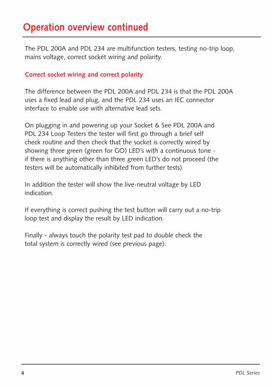
The PDL 200A and PDL 234 are multifunction testers, testing no-trip loop,mains voltage, correct socket wiring and polarity.
Correct socket wiring and correct polarity
The difference between the PDL 200A and PDL 234 is that the PDL 200Auses a fixed lead and plug, and the PDL 234 uses an IEC connector interface to enable use with alternative lead sets.
On plugging in and powering up your Socket & See PDL 200A and PDL 234 Loop Testers the tester will first go through a brief self check routine and then check that the socket is correctly wired by showing three green (green for GO) LED’s with a continuous tone - if there is anything other than three green LED’s do not proceed (the testers will be automatically inhibited from further tests).
In addition the tester will show the live-neutral voltage by LED indication.
If everything is correct pushing the test button will carry out a no-trip loop test and display the result by LED indication.
Finally - always touch the polarity test pad to double check the total system is correctly wired (see previous page).
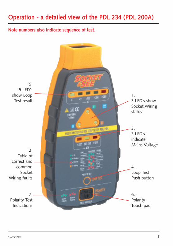
Operation - a detailed view of the PDL 234 (PDL 200A)
Note numbers also indicate sequence of test.
5overview
5.5 LED’s
show LoopTest result
2.Table of
correct andcommon
SocketWiring faults
7.Polarity Test
Indications
1.3 LED’s showSocket Wiringstatus
3.3 LED’s indicate Mains Voltage
4.Loop TestPush button
6.Polarity Touch pad
6 PDL Series
Operation overview continued
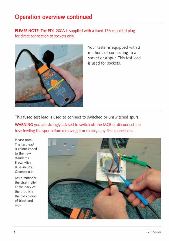
Please note:The test leadis colour codedto the newstandardsBrown=liveBlue=neutralGreen=earth.
(As a reminderthe strain reliefat the back ofthe prod is inthe old coloursof black andred).
Your tester is equipped with 2methods of connecting to asocket or a spur. This test lead is used for sockets.
WARNING you are strongly advised to switch off the MCB or disconnect the
fuse feeding the spur before removing it or making any first connections.
This fused test lead is used to connect to switched or unswitched spurs.
PLEASE NOTE: The PDL 200A is supplied with a fixed 13A moulded plugfor direct connection to sockets only.
7overview
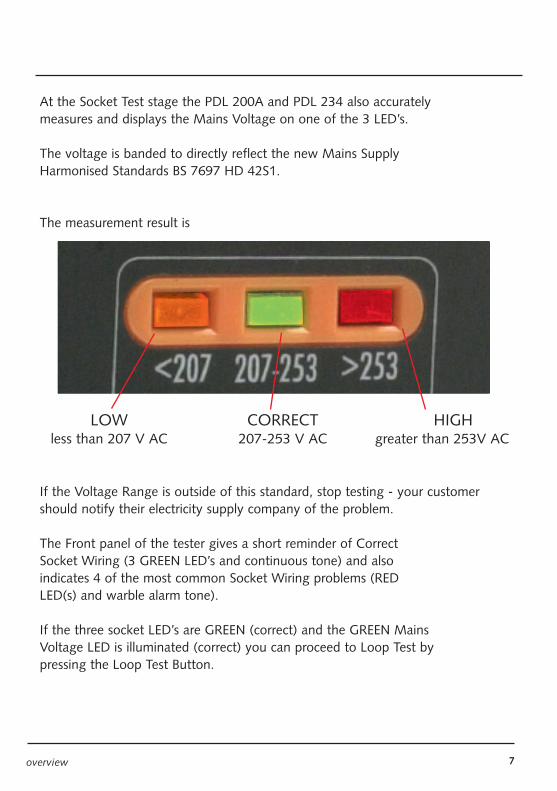
At the Socket Test stage the PDL 200A and PDL 234 also accuratelymeasures and displays the Mains Voltage on one of the 3 LED’s.
The voltage is banded to directly reflect the new Mains SupplyHarmonised Standards BS 7697 HD 42S1.
The measurement result is
LOW CORRECT HIGHless than 207 V AC 207-253 V AC greater than 253V AC
If the Voltage Range is outside of this standard, stop testing - your customer should notify their electricity supply company of the problem.
The Front panel of the tester gives a short reminder of CorrectSocket Wiring (3 GREEN LED’s and continuous tone) and alsoindicates 4 of the most common Socket Wiring problems (REDLED(s) and warble alarm tone).
If the three socket LED’s are GREEN (correct) and the GREEN MainsVoltage LED is illuminated (correct) you can proceed to Loop Test bypressing the Loop Test Button.
8 PDL Series
Loop Test
The 3 Socket Test LED’s will flash ORANGE to indicate a (no-trip)Loop Measurement Test is being made and unlike other no-trip LoopTesters the result will be given in a few secconds - if you wish the testcan be repeated to check the result.
For Guidance Only - Refer to the IEE Wiring Standards BS 7671.
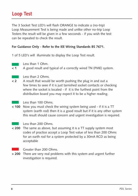
1 of 5 LED’s will illuminate to display the Loop Test result.
Less than 1 Ohm.< 1 A good result and typical of a correctly wired TN (PME) system.
Less than 2 Ohms.< 2 A result that would be worth pushing the plug in and out a
few times to seee if it is just tarnished socket contacts or checking where the socket is located - if it is the furthest point from the distribution board you may expect it to be a higher reading.
Less than 100 Ohms.< 100 Now you must check the wiring system being used - if it is a TT
system (earth rod) then it is a good result but if it is any other system this result should cause concern and urgent investigation is required.
Less than 200 Ohms.< 200 The same as above, but assuming it is a TT supply system most
codes of practice accept a Loop Test value of less than 200 Ohms for an earth rod for a system protected by a 30mA RCD as being acceptable
Greater than 200 Ohms.> 200 There are very real problems with this system and urgent further
investigation is required.
Loop Test
9overview
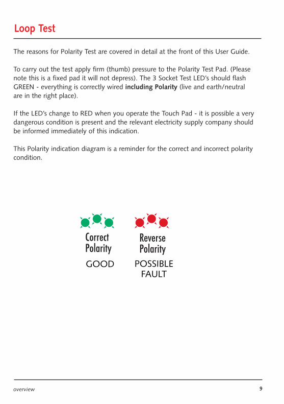
The reasons for Polarity Test are covered in detail at the front of this User Guide.
To carry out the test apply firm (thumb) pressure to the Polarity Test Pad. (Pleasenote this is a fixed pad it will not depress). The 3 Socket Test LED’s should flashGREEN - everything is correctly wired including Polarity (live and earth/neutralare in the right place).
If the LED’s change to RED when you operate the Touch Pad - it is possible a verydangerous condition is present and the relevant electricity supply company shouldbe informed immediately of this indication.
This Polarity indication diagram is a reminder for the correct and incorrect polaritycondition.
GOOD POSSIBLEFAULT
10 PDL Series
Socket Test Technology
The PDL 200A and PDL 234 use our well proven Socket Testing patented technology to indicate the socket is correctly wired.
Plugging the unit in and switching on mains supply automatically initiates thesocket test sequence.
If the socket is correctly wired the LED’s will be GREEN on this check.
If the socket is incorrectly wired one or more LED’s will go to FLASHING RED toindicate there is a a socket miss-wire or other fault.
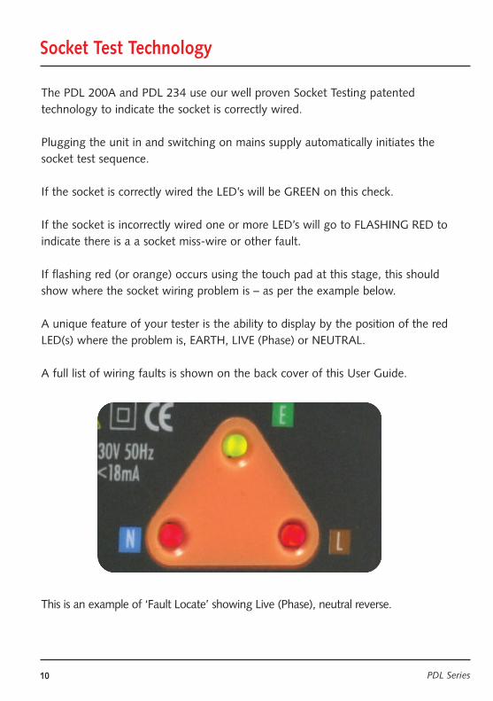
If flashing red (or orange) occurs using the touch pad at this stage, this shouldshow where the socket wiring problem is – as per the example below.
A unique feature of your tester is the ability to display by the position of the redLED(s) where the problem is, EARTH, LIVE (Phase) or NEUTRAL.
A full list of wiring faults is shown on the back cover of this User Guide.
This is an example of ‘Fault Locate’ showing Live (Phase), neutral reverse.
11
Socket & See Industrialwww.socketandsee.co.ukUnit 4, Century Road, High Carr Business Park,Newcastle, Sta�ordshire, UK, ST5 7UGT +44 (0)1782 567096F +44 (0)1782 567095
© Socket & See Limited (A division of the Kew Technik Group of companies)
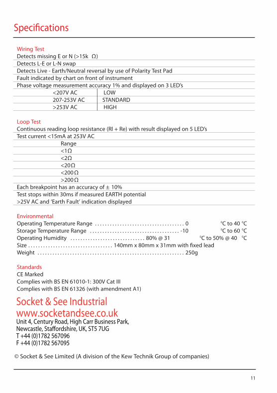
Wiring TestDetects missing E or N (>15k Ω)Detects L-E or L-N swapDetects Live - Earth/Neutral reversal by use of Polarity Test PadFault indicated by chart on front of instrumentPhase voltage measurement accuracy 1% and displayed on 3 LED’s
<207V AC LOW207-253V AC STANDARD>253V AC HIGH
Loop TestContinuous reading loop resistance (Rl + Re) with result displayed on 5 LED’sTest current <15mA at 253V AC
Range<1Ω<2Ω<20Ω<200Ω>200Ω
Each breakpoint has an accuracy of ± 10%Test stops within 30ms if measured EARTH potential >25V AC and ‘Earth Fault’ indication displayed
EnvironmentalOperating Temperature Range . . . . . . . . . . . . . . . . . . . . . . . . . . . . . . . . . . . . 0 0C to 40 0CStorage Temperature Range . . . . . . . . . . . . . . . . . . . . . . . . . . . . . . . . . . . . -10 0C to 60 0COperating Humidity . . . . . . . . . . . . . . . . . . . . . . . . . . . . . . 80% @ 31 0C to 50% @ 40 0CSize . . . . . . . . . . . . . . . . . . . . . . . . . . . . . . . . . . 140mm x 80mm x 31mm with �xed leadWeight . . . . . . . . . . . . . . . . . . . . . . . . . . . . . . . . . . . . . . . . . . . . . . . . . . . . . . . . . . . 250g
StandardsCE MarkedComplies with BS EN 61010-1: 300V Cat IIIComplies with BS EN 61326 (with amendment A1)
Speci�cations
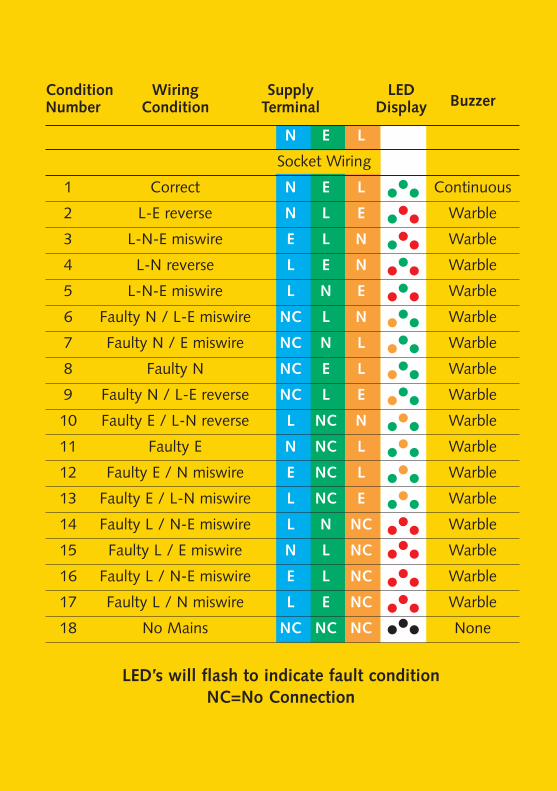
LED’s will flash to indicate fault conditionNC=No Connection
Condition Wiring Supply LED BuzzerNumber Condition Terminal Display
N E L
Socket Wiring
1 Correct N E L Continuous
2 L-E reverse N L E Warble
3 L-N-E miswire E L N Warble
4 L-N reverse L E N Warble
5 L-N-E miswire L N E Warble
6 Faulty N / L-E miswire NC L N Warble
7 Faulty N / E miswire NC N L Warble
8 Faulty N NC E L Warble
9 Faulty N / L-E reverse NC L E Warble
10 Faulty E / L-N reverse L NC N Warble
11 Faulty E N NC L Warble
12 Faulty E / N miswire E NC L Warble
13 Faulty E / L-N miswire L NC E Warble
14 Faulty L / N-E miswire L N NC Warble
15 Faulty L / E miswire N L NC Warble
16 Faulty L / N-E miswire E L NC Warble
17 Faulty L / N miswire L E NC Warble
18 No Mains NC NC NC None