Embed Size (px)
Citation preview
Publicly PAS 0001-5-2
Available Version: 1.0.1
Specification Date: 29 July 1998
Source: TETRAPOL Forum Work Item No: 0001
Key word: TETRAPOL
TETRAPOL Specifications;Part 5: Interface to Dispatch Centre;
Part 2: Speech Control Protocol Design on digital support
TETRAPOL FORUM
TETRAPOL Secretariat
Postal address: BP 40 78392 Bois d'Arcy CEDEX - FRANCETel.: +33 1 34 60 55 88 - Fax: +33 1 30 45 28 35
Copyright Notification: This is an unpublished work. The copyright vests in TETRAPOL Forum. All rightsreserved.©The information contained herein is the property of TETRAPOL Forum and no part may be reproduced or usedexcept as authorised by contract or other written permission. The copyright and the foregoing restriction onreproduction and use extend to all media in which the information may be embodied.Tetrapol Forum reserves the right to bring modifications to this document.

Page 2PAS 0001-5-2: Version 1.0.1
1998-TETRAPOL Forum 29/07/98This document is the property of TETRAPOL Forum and may not be copied or circulated without permission.

Page 3PAS 0001-5-2: Version 1.0.1
1998-TETRAPOL Forum 29/07/98This document is the property of TETRAPOL Forum and may not be copied or circulated without permission.
Contents
1. Scope ................................................................................................................................................. 5
2. Normative references.......................................................................................................................... 6
3. Definitions, symbols and abbreviations................................................................................................ 63.1 Definitions ............................................................................................................................... 63.2 Symbols .................................................................................................................................. 73.3 Abbreviations .......................................................................................................................... 7
4. Description of the interface between SwMI and DC ............................................................................. 84.1 Interface functional model ....................................................................................................... 84.2 Network layer protocol model .................................................................................................. 8
4.2.1 Protocol stack ........................................................................................................ 84.2.2 Services provided to higher layers ......................................................................... 94.2.3 Services required from lower layers ..................................................................... 10
4.3 System parameters and dimensioning requirements.............................................................. 11
5. Operational requirements.................................................................................................................. 125.1 Requirements on the TETRAPOL SwMI ................................................................................ 125.2 Requirements on the Dispatch Centre ................................................................................... 125.3 Requirements on a transit QSIG............................................................................................ 12
6. Signalling procedures at R6-I1 interface............................................................................................ 126.1 Introduction ........................................................................................................................... 126.2 Access gates management over R6-I1 .................................................................................. 12
6.2.1 Routing a call and selecting an access gate......................................................... 126.2.2 Non-discrimination between subscribers in the dispatch centre ............................ 12
6.3 Connection establishment procedure..................................................................................... 126.4 Connection refused ............................................................................................................... 126.5 Connection release procedure ............................................................................................... 136.6 Speech control procedures .................................................................................................... 13
6.6.1 Introduction.......................................................................................................... 136.6.2 PTT service ......................................................................................................... 136.6.3 Talking party identification ................................................................................... 146.6.4 Global diagram for PTT and TPI service.............................................................. 14
6.7 Handling of protocol error conditions ..................................................................................... 14
7. Call states at R6-I1 interface ............................................................................................................. 157.1 Introduction ........................................................................................................................... 157.2 Call states at R6-I1 DC side................................................................................................... 15
7.2.1 Connection states ................................................................................................ 157.2.2 PTT states ........................................................................................................... 15
7.3 Call states at R6-I1 SwMI side............................................................................................... 167.3.1 Connection states ................................................................................................ 167.3.2 PTT states ........................................................................................................... 16
8. Message coding requirements at R6-I1 interface............................................................................... 178.1 QSIG messages at R6-I1 interface ........................................................................................ 17
8.1.1 Use of QSIG messages ....................................................................................... 178.1.2 Applicable QSIG messages ................................................................................. 178.1.3 Messages for general procedure .......................................................................... 188.1.4 Messages for circuit mode call control ................................................................. 188.1.5 Messages for layer management ......................................................................... 218.1.6 Messages for additional network features ............................................................ 22
8.2 PTT and TPI operations ........................................................................................................ 22

Page 4PAS 0001-5-2: Version 1.0.1
1998-TETRAPOL Forum 29/07/98This document is the property of TETRAPOL Forum and may not be copied or circulated without permission.
8.2.1 Purpose................................................................................................................228.2.2 Facility information element..................................................................................228.2.3 Other information elements ..................................................................................23
8.3 Operations and operation arguments......................................................................................238.3.1 Operation code.....................................................................................................238.3.2 PTT service..........................................................................................................248.3.3 Talking party identification ....................................................................................24
8.4 Information elements..............................................................................................................258.4.1 Information element identifier ...............................................................................258.4.2 Context specific tag ..............................................................................................258.4.3 Protocol discriminator ...........................................................................................258.4.4 Call reference.......................................................................................................258.4.5 Message type .......................................................................................................258.4.6 Bearer capability...................................................................................................258.4.7 Call state ..............................................................................................................268.4.8 Called party number .............................................................................................268.4.9 Called party subaddress .......................................................................................268.4.10 Calling party number ..........................................................................................268.4.11 Calling party subaddress.....................................................................................268.4.12 Cause.................................................................................................................268.4.13 Channel identification .........................................................................................268.4.14 Connected number .............................................................................................268.4.15 Connected subaddress .......................................................................................268.4.16 High layer compatibility.......................................................................................268.4.17 Lower layer compatibility ....................................................................................268.4.18 Progress indicator...............................................................................................278.4.19 Restart indicator .................................................................................................278.4.20 Segmented message..........................................................................................278.4.21 Sending complete...............................................................................................278.4.22 Party category ....................................................................................................278.4.23 Transit counter....................................................................................................27
9. History ...............................................................................................................................................28

Page 5PAS 0001-5-2: Version 1.0.1
1998-TETRAPOL Forum 29/07/98This document is the property of TETRAPOL Forum and may not be copied or circulated without permission.
1. Scope
The TETRAPOL R6 interface to a dispatch centre is a network-to-network interface between oneTETRAPOL switching and management infrastructure (SwMI) and one dispatch centre (DC).
The speech control protocol of the R6.I1 is described in this document. It shall supply :
- speech support- PTT service
This document corresponds to sub-part 5.2 of the TETRAPOL specification of the interface to a dispatchcentre, which is divided into five sub-parts:
- Part 5.1 Technical requirements;- Part 5.2 Speech control protocol on digital interface protocol design;- Part 5.3 reserved- part 5.4 Service control protocol design;- part 5.5 Service control messages.
The speech related signalling protocol shall use protocol stack for interconnecting Private IntegratedServices Network eXchanges (PINXs) to form Private Integrated Services Network (PISN).
This sub-part specifies and defines the signalling protocol for the support of the TETRAPOL connectioncontrol services, between the access gate (AG) functional entity of a TETRAPOL SwMI and the dispatchposition switch (DPS) functional entity of a dispatch centre, both seen as private integrated networkexchanges (PINXs) at the Q reference point.
This interface basically features a semi-permanent link between an access gate and a dispatch centreswitch with speech control signalling between AG and DPS.

Page 6PAS 0001-5-2: Version 1.0.1
1998-TETRAPOL Forum 29/07/98This document is the property of TETRAPOL Forum and may not be copied or circulated without permission.
2. Normative references
This PAS incorporates by dated and undated reference, provisions from other publications. Thesenormative references are cited at the appropriate places in the text and the publications are listedhereafter.
[1] PAS 0001-1-1: "TETRAPOL Specifications; General Network Design;Reference Model".
[2] PAS 0001-5-1: "TETRAPOL Specifications; Interface to dispatch centre;technical requirements Specifications".
[3] PAS 0001.5.4 : « TETRAPOL Specifications; Interface to dispatch centre;Service control protocol »
[4] PAS 0001.5.5 : « TETRAPOL Specifications; Interface to dispatch center;Service control messages »
[5] ETS 300 172 : "Private integrated services network (PISN); Inter-exchangesignalling protocol; Circuit mode basic services".
[6] ETS 300 239 : "Private integrated services network (PISN) Inter-exchangesignalling protocol; generic functional protocol for the support of supplementaryservices".
[7] ETS 300 170 "Private Telecommunication network (PTN) Data link layerprotocol at the Q reference point for signalling channel between two privatetelecommunication network exchanges".
[8] ETS 300 102 « Integrated Services digital Network (ISDN) : user-networkinterface layer 3. Specifications for basic call control ».
3. Definitions, symbols and abbreviations
3.1 Definitions
The definitions from the dispatch centre technical requirements [2] apply, including the followingdefinitions:
Access gate (AG): Functional entity in the TETRAPOL SwMI, radio connected or line connected, thatsupplies voice and signalling facilities to the dispatch centre.
Additional Network Feature (ANF): A capability provided by a private services network exchange abovethe basic call. In this specification, the additional network features refer to the extra-capabilities providedabove QSIG basic call in order to handle TETRAPOL services (for example PTT).
Base station (BS): Interface unit containing a set of radio transmitters/receivers providing access tocommunications with radio terminals and radio connected access gates. May also be wire connected(LABS).
DC-Organisation: A DC-organisation consists of a set of trunks. The DC-organisation serves foradministrative purposes in the dispatch centre.
Dispatch Access Controller (DAC): Functional entity within the TETRAPOL system that acts as anService Control Point (SCP) for the dispatch centre.
Dispatch Centre (DC): The dispatch centre shall include a dispatch control server (DCS) and a dispatchposition switch (DPS) which connects dispatch positions (DPs) to the TETRAPOL network. The dispatchcentre provides the dispatchers from one or several DC-organisations with incoming and outgoingTETRAPOL voice services and system monitoring. It may also supply call centre facilities, e.g.automatic call distribution, that are however out of the scope of the TETRAPOL system.

Page 7PAS 0001-5-2: Version 1.0.1
1998-TETRAPOL Forum 29/07/98This document is the property of TETRAPOL Forum and may not be copied or circulated without permission.
Dispatch control server (DCS): Functional entity within the dispatch centre that handles queries from thedispatch positions.
Dispatch Position Switch (DPS): Call control functional entity within the dispatch centre that handlesvoice connections over the R6.I1 interface to the TETRAPOL SwMI.
Dispatch Position (DP): Work position connected to the DPS and to the DCS where the dispatchersoperate.
Dispatcher: A subscriber of the dispatch centre that uses a dispatch position.
Incoming call: Call from SwMI to DC
Outgoing call: Call from DC to SwMI
QSIG : Protocol at the Q reference point between private networks, used here at the R6.I1 TETRAPOLinterface between the SwMI and the DC.
System Terminal: Service access reference point provided to the user by the system. System terminals(STs) are radio terminals (RTs), line connected terminals (LCTs).
System: The TETRAPOL system is composed of the large area fixed infrastructure (SwMI) callednetwork and of the system terminals allowing user access to the available services.
Switching and Management Infrastructure (SwMI): The SwMI shall be a sub-system of the TETRAPOLnetwork. It includes two sub-systems: the base station and the radio switch (RSW) network. The SwMIalso includes one or several DACs, the operation and maintenance centre (OMC) and the keymanagement centre (KMC). OMC and KMC are outside of the scope of the present specification.
3.2 Symbols
Not applicable.
3.3 Abbreviations
The abbreviations from document [2] apply, including the following abbreviations:
AG access gate at SwMI side of the R6-I1 and R6.I3 interfacesAH Access handlerANF Additional network featuresBRI Basic rate interfaceDAC Dispatch access control functional entity in the SwMIDC Dispatch centreDCS Dispatch centre server functional entity in the DCDPS Dispatch position switch functional entity in the DCIE Information Element in a messagePDU Protocol data unitPICS Protocol implementation conformance statementPTT Push to talk serviceRD Speech receive detection in the PTT serviceR6 Reference point for the TETRAPOL SwMI-Dispatch centre interfaceSwMI TETRAPOL Switching and management infrastructureTI Speech transmit indication in the PTT serviceTPI Talking party identification

Page 8PAS 0001-5-2: Version 1.0.1
1998-TETRAPOL Forum 29/07/98This document is the property of TETRAPOL Forum and may not be copied or circulated without permission.
4. Description of the interface between SwMI and DC
4.1 Interface functional model
The functional model at R6 reference point shall consist of the following functional entities:
AG Access gateDAC Dispatch access controllerDPS Dispatch position switchDCS Dispatch control server
The allocation of the functional entities to physical equipments shall be as follows:
- AG and DAC shall be located in the TETRAPOL SwMI;- DPS and DCS shall be located in the dispatch centre.
The R6 reference point from the TETRAPOL reference model [1] is split between two logical routes andrelated interfaces :
- one dedicated to circuit mode speech transmission and related signalling at network layer betweenAG and DPS, that is specified in this document.
- one dedicated to complementary call related services and non call related services provided to theDC, between DAC and DCS, that is specified in documents [3] and [4],
referred to as service control signalling at applicative layer between DAC and DCS.
The mapping of the R6 information flows on R6-I1 circuit related signalling and R6-I3 service controlsignalling are described hereafter.
The speech control protocol over R6.I1 takes the following assumptions upon the R6.I3 interface :
- allocates an access gate to each TETRAPOL call handled over R6 interface- implements service control functions related to TETRAPOL calls;
The figure for DC signalling configuration shows the functional entities and their relationships.
Voice traffic
Speech signalling
TETRAPOL SwMI-Network boundary
R6.I3
R6.I1
Dispatch Centre
service control signalling DAC
AG
DCS
DPS
AG remote control &
Figure 1: DC signalling over R6 interface:
For each call over the R6 interface, the logical access point instance at the SwMI side is referred to asan access gate (AG) instance. During a call involving one or several TETRAPOL subscribers and theDC, there shall be one AG instance per traffic channel used over R6-I1 interface. The AG shall beallocated by the DCS instance. The AG also provide the DAC with the control signalling from the SwMI.
4.2 Network layer protocol model
4.2.1 Protocol stack
The R6.I1 interface shall be based on a QSIG circuit mode protocol on basic rate interface.

Page 9PAS 0001-5-2: Version 1.0.1
1998-TETRAPOL Forum 29/07/98This document is the property of TETRAPOL Forum and may not be copied or circulated without permission.
ANF_SwMI service ANF_DC service
SwMI access DC access
AG
QSIG_AGbasic call +
QSIG_DPSQ
LAP_D LAP_D
BRI BRI
R6.I1
DPS
generic featuresbasic call +
generic features
Figure 2: Protocol stack at R6-I1 interface
The normative references are listed as follows:
Link access protocol on channel D (LAP_D) : [6]Basic rate interface at physical layer (BRI) : [7]
4.2.2 Services provided to higher layers
4.2.2.1 Service requirements
The list of services that are available to dispatchers is described in the technical requirements sub-part5.1 of this specification [2].
The circuit related signalling is based on QSIG protocol and shall provide a semi-permanent connectionbetween each AG and the DPS. Additional network functions provide the enhancements needed tosupport the TETRAPOL services.
The TETRAPOL SwMI and the dispatch position switch (DPS) shall be two independent networks, withtheir own numbering plan.
4.2.2.2 Service primitives
This clause describes the service primitives provided to higher layers at SwMI side and DC side of theR6-I1 interface.
The prefix of a primitive refers to the functional entity that owns the primitive, either AG_ or DPS_.
_REQ suffix applies to the requesting side, whereas _IND suffix applies to the receiving side of theinterface.

Page 10PAS 0001-5-2: Version 1.0.1
1998-TETRAPOL Forum 29/07/98This document is the property of TETRAPOL Forum and may not be copied or circulated without permission.
Table 1: Primitives provided to higher layers at SwMI side
Primitive at AG side Associated message way Primitive at DC side meaningAG_SETUP_IND QSIG_SETUP ç DPS_SETUP_REQ line connection
requestedAG_SETUP_CONF QSIG_CONNECT è DPS_SETUP_CONF line connection
achievedAG_CONNECT_IND QSIG_CONNECT_ACK ç DPS_CONNECT_CONF line connectedAG_RELEASE_IND QSIG_DISCONNECT ç DPS_RELEASE_REQ line release requestedAG_RELEASE_CONF QSIG_RELEASE è DPS_RELEASE_CONF line release achievedAG_IDLE_IND QSIG_RELEASE_COMPLE
TEçè DPS_IDLE_IND line released
AG_TPI_REQ QSIG_FACILITY è DPS_TPI_IND parking party identityAG_PTT_IND QSIG_FACILITY ç DPS_PTT_REQ beginning of PTTAG_PTT_RELEASE_IND
QSIG_FACILITY ç DPS_PTT_RELEASE_REQ
end of PTT
AG_TI_ACT_REQ QSIG_FACILITY è DPS_TI_ACT_IND AG transmittingAG_TI_DEACT_REQ QSIG_FACILITY è DPS_TI_DEACT_IND AG no more
transmissionAG_RD_ACT_REQ QSIG_FACILITY è DPS_RD_ACT_IND AG receivingAG_RD_DEACT_REQ QSIG_FACILITY è DPS_RD_DEACT_IND AG no more receiving
The AG shall be a slave of the DC regarding connection management. All speech-control flows shall besent as remote operations in QSIG_FACILITY messages, once the link is established between the AGand DC.
The connection between the DPS and each AG is semi-permanent and shall be set-up duringinitialisation process.
The following primitives :
- AG_RELEASE_IND- DPS_RELEASE_REQ- DPS_RELEASE_CONF- DPS_IDLE_IND
should not be used during operational service, except if the DC has a reason to release the connection(typically in action against protocol errors).
The primitive AG_IDLE_IND may be used by the AG in answer to some protocol errors.
4.2.3 Services required from lower layers
4.2.3.1 R6.I1 network layer
It shall use QSIG protocol [5] and [6].
The following rules shall apply to level 3 messages :
- messages shall not be segmented- message length shall be limited to a single LAP-D segment (260 bytes)- FACILITY messages length may contain in theory up to 255 bytes in the limit of the maximum
message size.
Information elements Call Reference and Channel Identification shall be coded as described indocument [5], even on BRI interface :
- Call Reference length = 3- Channel Identification length = 5

Page 11PAS 0001-5-2: Version 1.0.1
1998-TETRAPOL Forum 29/07/98This document is the property of TETRAPOL Forum and may not be copied or circulated without permission.
4.2.3.2 R6.I1 Data link layer
The D channel and a single B channel shall be used at R6.I1 interface.
The network layer procedures shall use the data link layer (LAP-D) services and shall receive informationfrom the data link layer by using the primitives designed for the link access protocol on D channel of theISDN user-network interface, defined in [6].
The TETRAPOL R6.I1 AG interface side shall be configured as a terminal side equipment (TE1). Thedispatch position switch functional entity of the dispatch centre shall be configured as a network sideequipment (TN2).
The data link connection shall be established before any of the procedures defined in this specificationcan be performed.
The LAP-D shall be set up by the AG.
The requested LAP-D parameters shall be the following :
- TEI = 00h : value reserved to QSIG in recommendation [6]- segment size = 260 bytes : minimum value foreseen in recommendation [6]
4.2.3.3 R6.I1 Physical layer
The voice interface shall be built upon B channels that shall handle bi-directional traffic.
The following rules apply for interface configuration:
- The TETRAPOL SwMI side of the R6-I1 interface shall be configured as the terminal side;- The DPS shall be configured as the network side;- Point to point connections shall be used;. The clock shall be supplied by the DPS.
The following rules apply for power at R6-I1 interface:
- The TETRAPOL access gate equipments shall be locally powered;- The interworking between TETRAPOL and dispatch centre equipments shall be possible with or
without power feed detection by the TETRAPOL SwMI.
4.3 System parameters and dimensioning requirements
The traffic channels over R6-I1 shall be provided by an ISDN circuit mode bearer service with a basicrate interface and T0 basic rate interface shall be used over R6-I1 interface in this version of thespecification.
The physical layer of the basic rate interface is defined in document [7].
The traffic channel with the lower channel number (B1) should be used exclusively, without channelnegotiation.
The AG and DC additional network feature entities shall not be temporised, i.e. they shall not handle anyown timer and they shall synchronise on QSIG timers and call control timers.

Page 12PAS 0001-5-2: Version 1.0.1
1998-TETRAPOL Forum 29/07/98This document is the property of TETRAPOL Forum and may not be copied or circulated without permission.
5. Operational requirements
5.1 Requirements on the TETRAPOL SwMI
Basic call procedures and connection oriented generic functions shall apply as specified in [5] and [6].The Network Facility Extension shall be a mandatory part of all facility information elements.
5.2 Requirements on the Dispatch Centre
Basic call procedures and generic functions shall apply as specified in [5] and [6]. Addresses shall beprovided in the addressing plan of the called system.
5.3 Requirements on a transit QSIG
There shall be not transit node between an AG and a DC.
6. Signalling procedures at R6-I1 interface
6.1 Introduction
This clause specifies in detail how:- the access gates are handled at the dispatch centre interface,- the semi-permanent connection is established over R6-I1 interface with QSIG protocol,- how the speech related control operations flow over the connection.
6.2 Access gates management over R6-I1
6.2.1 Routing a call and selecting an access gate
Call routing and access gate selecting is handled over R6.I3 interface.
The DPS shall select the same access gate on R6.I1 interface for speech service.
6.2.2 Non-discrimination between subscribers in the dispatch centre
The protocol at R6-I1 shall be able to work regardless of the type of dispatch positions involved in a callmay be basic telephone sets or computerised dispatch position, connected to the DC directly or via anexternal public or private network.
Nevertheless PTT and TPI service will not be available with a basic telephone set or a network line.
6.3 Connection establishment procedure
Connections between AG and DC shall be established prior and regardless to any TETRAPOL call.
The call shall be set up by the DCS in accordance with QSIG basic call protocol as described in [5].
AG DPSDPS_SETUP_REQ (request for connection)QSIG_SETUP
QSIG_CONNECT_ACK
QSIG_CONNECT DPS_SETUP_CONF
DPS_CONNECT_CONF (line operational)
AG_SETUP_IND
AG_SETUP_CONF (conection achieved)
AG_CONNECT_CONF
6.4 Connection refused
In some cases, the AG may refuse to set up the call (typically, wrong called party address).
AG DPSDPS_SETUP_REQ (request for connection)QSIG_SETUP
QSIG_RELEASE_COMPLETE DPS_IDLE_CONF
AG_SETUP_IND
AG_IDLE_CONF (conection refused)

Page 13PAS 0001-5-2: Version 1.0.1
1998-TETRAPOL Forum 29/07/98This document is the property of TETRAPOL Forum and may not be copied or circulated without permission.
6.5 Connection release procedure
Connections between AG and DC shall be kept established regardless of any TETRAPOL call.
Nevertheless, it may be assumed that the DC, for its own purpose, needs to release the connection : theAG will not be available as long as the connection has not been restored.
The call shall be released by the DCS in accordance with QSIG basic call protocol as described in [5].
AG DPSDPS_RELEASE_REQ (request for release)QSIG_DISCONNECT
QSIG_RELEASE
QSIG_RELEASE_COMPLETE
DPS_RELEASE_CONF
DPS_IDLE_CONF (line idle again)
AG_RELEASE_IND
AG_RELEASE_CONF (line released)
AG_IDLE_CONF
6.6 Speech control procedures
6.6.1 Introduction
The protocol over R6-I1 interface shall support speech control procedures for half duplex calls with push-to-talk (PTT) remote operation.
6.6.2 PTT service
6.6.2.1 Service description
After the connection has been set up, the Push-to-talk supplementary service shall enable a dispatcher,participating in an half duplex voice call over a traffic channel of the R6-I1 interface :
- to request permission to transmit from DC to SwMI- to request the end of transmission from DC to SwMI- to be informed that speech is being transmitted from DC to SwMI- to be informed that speech is no longer transmitted from DC to SwMI- to be informed that speech is being received from SwMI to DC- to be informed that speech is no longer received from SwMI to DC.
When invoked, this supplementary service shall not have any interaction with other services.
The SwMI shall handle the push-to-talk arbitration.
It several dispatchers are engaged in a call with the same AG, the DC shall supply PTT arbitration inorder to make sure that the speech of only one of them will be transmitted to the SwMI.
PTT priority level may be adjusted by the means of a command sent over R6.I3 interface
It is recommended to use two priority levels that shall have both an higher priority level than otherTETRAPOL subscriber :
- Normal DC priority for call between a dispatcher and any type of TETRAPOL call- Increased DC priority for calls that connect together two or more TETRAPOL group
communications with a transit through the DC.
6.6.2.2 Information flows
The information flow from the DC to the SwMI across the interface shall be as follows:
- PTT_REQUEST shall be received by the SwMI as a request to transmit the speech signal from theDC to the SwMI.
- PTT_RELEASE shall be received by the SwMI as an order to cease transmitting from the DC tothe SwMI.

Page 14PAS 0001-5-2: Version 1.0.1
1998-TETRAPOL Forum 29/07/98This document is the property of TETRAPOL Forum and may not be copied or circulated without permission.
The information flow from the SwMI to the DC across the interface shall be as follows:
- TI_ACT shall be sent by the SwMI when speech transmission from DC to the SwMI is beginning.
- TI_DEACT shall be sent by the SwMI to indicate that the speech transmission from the DC to theSwMI has ceased.
- RD_ACT shall be sent by the SwMI to indicate that speech reception from SwMI to DC isbeginning
- RD_DEACT shall be sent by the SwMI to indicate that speech reception from SwMI to DC hasceased.
6.6.3 Talking party identification
During an on-going communication, the identity of the talking TETRAPOL subscriber may be providedboth on R6.I1 and R6.I3 interfaces. In some cases it may be unavailable.
Talking party identity is transmitted from SwMI to DC, never from DC to SwMI.
6.6.4 Global diagram for PTT and TPI service
Hereafter the following sequence :
- Speech transmitted from DC- Speech received by DC, with talking party identity (optional).
AG DPS
AG_PTT_IND( call_id,PTT_REQUEST_TAG)
DPS_PTT_EQ(call_id) request for PTTQSIG_FACILITY(call_ref, PTT_OP)
AG_TI_ACT_REQ(call_id)transmission begins DPS_TI_ACT_IND(call_id)QSIG_FACILITY(call_ref, PTT_OP)TI_ACT_TAG)
AG_TI_DEACT_REQ(call_id) end of transmission DPS_TI_DEACT_IND(call_id)QSIG_FACILITY(call_ref, PTT_OP)TI_DEACT_TAG)
AG_PTT_RELEASE_IND(call_id) DPS_PTT_RELEASE_REQ(call_id) request forQSIG_FACILITY(call_ref, PTT_OP)
PTT_RELEASE_TAG)
AG_RD_DEACT(call_id) end of reception DPS_RD_DEACT(call_id)QSIG_FACILITY(call_ref, PTT_OP)RD_DEACT_TAG)
AG_RD_ACT(call_id) reception begins DPS_RD_ACT(call_id)QSIG_FACILITY(call_ref, PTT_OP)RD_ACT_TAG)
(AG_TPI_RQ(call_id, addres)) address of talking (DPS_TPI_IND(call_id, address)))(QSIG_FACILITY(call_ref,TPI_OP))TPI_ADDRESS_TAG)
party received
end of PTT
6.7 Handling of protocol error conditions
The handling of QSIG protocol error conditions shall apply as defined in [5] with the following additions.
The DC shall be able to decide whenever the connection over R6-I1 shall be released, when the QSIGprotocol does not handle the event by itself. The call is not released on R6.I3 interface but no speech isavailable anymore.
The AG shall be able to send RELEASE_COMPLETE by itself in all cases foreseen by the protocol,typically on SETUP error.
Both sides shall be able to send STATUS message with error cause.

Page 15PAS 0001-5-2: Version 1.0.1
1998-TETRAPOL Forum 29/07/98This document is the property of TETRAPOL Forum and may not be copied or circulated without permission.
7. Call states at R6-I1 interface
7.1 Introduction
The call control states that may exist at the AG side and at the DC side of the circuit mode R6-I1interface are defined in the following informative sub-clauses.
The state of the call on R6.I1 interface conditions the availability of speech service on calls that shall beset up onto R6.I3 interface.
7.2 Call states at R6-I1 DC side
7.2.1 Connection states
The connection states shall include the following macro-states, which may be subdivided in moredetailed states, including those defined in QSIG [5].
DPS_IDLE (DC 0)
This state shall exist when no connection control instance is allocated to handle the connection over R6-I1 interface.
The AG should not support any call. If any, speech service is not available.
DPS_CONNECTION_SETUP (DC 1)
This state shall exist during the connection establishment phase, from the initial request to set-up untilthe link is through-connected over R6.I1 or until the connection establishment over R6-I1 interface isaborted.
The AG should not support any call. If any, speech service is not available.
DPS_CONNECTED (DC 2)
The link is said to be in the connected state when it has been established over R6-I1 interface and norequest to disconnect it has been received.
The AG may support a call. If any, speech service is available.
DPS_DISCONNECTING (DC 3)
This state shall exist when the link is being disconnected.
The AG should not support any call. If any, the speech service is not available.
7.2.2 PTT states
The PTT states shall be valid if the call state is DPS_CONNECTED with a traffic channel available andthrough-connected.
Nevertheless, it is ineffective if no call has been set up over R6.I3 interface.
SILENT (DC_PTT 0)
This state shall exist when no participant is talking. It may exist with or without an ongoing call over R6.I3interface.

Page 16PAS 0001-5-2: Version 1.0.1
1998-TETRAPOL Forum 29/07/98This document is the property of TETRAPOL Forum and may not be copied or circulated without permission.
TRANSMIT_REQUESTED (DC_PTT 1)
This state shall exist when the DC has requested permission to transmit but has received no answer yetfrom the SwMI. It may exist with or without an ongoing call over R6.I3 interface but in this last case, PTTwill not be granted.
TALKING (DC_PTT 2)
This state shall exist when the DC is transmitting speech on the traffic channel into the SwMI. It mayexist only with an ongoing call over R6.I3 interface.
TRANSMIT_CEASE (DC_PTT 3)
This state shall exist when the DC has requested to cease transmitting but has received no answer yetfrom the SwMI. It may exist only with an ongoing call over R6.I3 interface.
LISTENING (DC_PTT 4)
This state shall exist when the DC is receiving speech on the traffic channel from the SwMI It may existonly with an ongoing call over R6.I3 interface.
7.3 Call states at R6-I1 SwMI side
7.3.1 Connection states
The connection states shall include the following macro-states, which may be subdivided in moredetailed states, including those defined in QSIG [5].
AG _IDLE (AG 0)
This state shall exist when no connection control instance is allocated to handle the connection over R6-I1 interface.
AG _CONNECTION_SETUP (AG 1)
This state shall exist during the connection establishment phase, from the initial request to set-up overR6-I1 interface until the link is through-connected over R6 or until the establishment over R6-I1 interfaceis aborted.
AG _CONNECTED (AG 2)
The link is in the connected state when it has been established over R6-I1 interface and inside of theSwMI, and no request to release the connection has been received.
AG _DISCONNECTING (AG 3)
This state shall exist when the link is being disconnected.
7.3.2 PTT states
IDLE (AG _PTT 0)
This state shall exist when no call has been set up over R6.I3 interface.
SILENT (AG _PTT 1)
This state shall exist when a call has been set up over R6.I3 interface , but no participant is talking.

Page 17PAS 0001-5-2: Version 1.0.1
1998-TETRAPOL Forum 29/07/98This document is the property of TETRAPOL Forum and may not be copied or circulated without permission.
INCOMING (AG _PTT 2)
This state shall exist when a call has been set up over R6.I3 interface and when the speech istransmitted from the R6-I1 interface into the SwMI.
OUTGOING (AG _PTT 3)
This state shall exist when a call has been set up over R6.I3 interface and when speech is transmittedfrom the SwMI onto the R6-I1 interface.
Page 18PAS 0001-5-2: Version 1.0.1
1998-TETRAPOL Forum 29/07/98This document is the property of TETRAPOL Forum and may not be copied or circulated without permission.
8. Message coding requirements at R6-I1 interface
8.1 QSIG messages at R6-I1 interface
8.1.1 Use of QSIG messages
This clause defines the minimum requirements to the QSIG network messages [5] [6] for the support ofthe Additional Network Features between a TETRAPOL SwMI and a Dispatch Centre. The tables in thisclause follow the QSIG conventions [5], with the following modification :
For each message a table indicates which standard information elements shall be inserted by theTETRAPOL SwMI for messages sent to the dispatch centre, and which standard optional informationelements shall be recognised by the TETRAPOL SwMI for messages received from the dispatch centre.Other standard optional information elements may be ignored by the TETRAPOL SwMI. For eachinformation element or field in the tables, it specifies whether inclusion status shall be:
- mandatory (M) for both TETRAPOL conformance and QSIG conformance;- mandatory (TM) for TETRAPOL conformance, though optional for QSIG conformance;- optional (O) for both QSIG and TETRAPOL conformance;- optional (TO) for TETRAPOL conformance and not related to QSIG conformance;- optional (TN) for QSIG conformance and not related to TETRAPOL conformance, i.e. ignored when
received and not sent by the TETRAPOL SwMI;- conditional (C) on the presence or value of another information element.
TETRAPOL conformance is described in the PICS proforma attached in annex A of this document.QSIG conformance is described in the PICS proforma of the QSIG specification [5] [6].
Whenever a message is sent over the R6 interface, according to the procedure defined above, it shallcontain the mandatory information elements marked (M) or (TM), and optionally any combination of theoptional information elements marked (O) or (TO). The TETRAPOL SwMI shall not send any informationelement marked (TN).
8.1.2 Applicable QSIG messages
QSIG basic call control messages are defined in [5]. The messages supporting TETRAPOL ApplicationPDUs transportation are defined in [6] and may be supported over the interface as described in thefollowing table for the purpose of this interface. It is mandatory to support at least the messages and theinformation elements described hereafter; support of other messages or other information elements isoptional:

Page 19PAS 0001-5-2: Version 1.0.1
1998-TETRAPOL Forum 29/07/98This document is the property of TETRAPOL Forum and may not be copied or circulated without permission.
Table 2: QSIG messages used at the SwMI-DC interface
TETRAPOL SwMI-DC interface
support
NormativeReference
Call establishment messagesQSIG_ALERTING not used [6]QSIG_CALL PROCEEDING not used [5]QSIG_CONNECT SwMI->DC [6]QSIG_CONNECT ACKNOWLEDGE DC->SwMI [5]QSIG_PROGRESS not used [6]QSIG_SETUP DC->SwMI [6]QSIG_SETUP ACKNOWLEDGE not used [5]Call clearing messagesQSIG_DISCONNECT DC->SwMI [6]QSIG_RELEASE SwMI->DC [6]QSIG_RELEASE COMPLETE both ways [6]QSIG_RESTART DC->SwMI [5]QSIG_RESTART ACKNOWLEDGE SwMI->DC [5]Messages for call control informationQSIG_INFORMATION not used [5]QSIG_FACILITY both ways [6]QSIG_NOTIFY not used [6]QSIG_SEGMENT not used [5]Messages for general proceduresQSIG_STATUS both ways [5]QSIG_STATUS ENQUIRY DC->SwMI [5]
8.1.3 Messages for general procedure
8.1.3.1 QSIG_STATUS
This message may be received by the SwMI to indicate a QSIG error condition. This message shall besent by the SwMI as an answer to a status enquiry.
The QSIG specification [5] shall apply with the following indications:
Table 3: QSIG_STATUS protocol data unit
Message type: QSIG_STATUS Direction: bothInformation element Reference Status Length
Protocol discriminator 8.4.3 M 1Call reference 8.4.4 M 3Message type 8.4.5 M 1Cause 8.4.12 M 4-32Call state 8.4.7 M 3
8.1.3.2 QSIG_STATUS_ENQUIRY
This message shall not be sent over R6 interface.
8.1.4 Messages for circuit mode call control
8.1.4.1 QSIG_ALERTING
This message shall not be used.
Page 20PAS 0001-5-2: Version 1.0.1
1998-TETRAPOL Forum 29/07/98This document is the property of TETRAPOL Forum and may not be copied or circulated without permission.
8.1.4.2 QSIG_CALL PROCEEDING
This message may not be used.
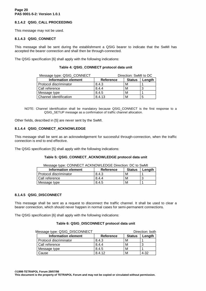
8.1.4.3 QSIG_CONNECT
This message shall be sent during the establishment a QSIG bearer to indicate that the SwMI hasaccepted the bearer connection and shall then be through-connected.
The QSIG specification [6] shall apply with the following indications:
Table 4: QSIG_CONNECT protocol data unit
Message type: QSIG_CONNECT Direction: SwMI to DCInformation element Reference Status Length
Protocol discriminator 8.4.3 M 1Call reference 8.4.4 M 3Message type 8.4.5 M 1Channel identification 8.4.13 M 5
NOTE: Channel identification shall be mandatory because QSIG_CONNECT is the first response to aQSIG_SETUP message as a confirmation of traffic channel allocation.
Other fields, described in [5] are never sent by the SwMI.
8.1.4.4 QSIG_CONNECT_ACKNOWLEDGE
This message shall be sent as an acknowledgement for successful through-connection, when the trafficconnection is end to end effective.
The QSIG specification [5] shall apply with the following indications:
Table 5: QSIG_CONNECT_ACKNOWLEDGE protocol data unit
Message type: CONNECT ACKNOWLEDGE Direction: DC to SwMIInformation element Reference Status Length
Protocol discriminator 8.4.3 M 1Call reference 8.4.4 M 3Message type 8.4.5 M 1
8.1.4.5 QSIG_DISCONNECT
This message shall be sent as a request to disconnect the traffic channel. It shall be used to clear abearer connection, which should never happen in normal cases for semi-permanent connections.
The QSIG specification [6] shall apply with the following indications:
Table 6: QSIG_DISCONNECT protocol data unit
Message type: QSIG_DISCONNECT Direction: bothInformation element Reference Status Length
Protocol discriminator 8.4.3 M 1Call reference 8.4.4 M 3Message type 8.4.5 M 1Cause 8.4.12 M 4-32

Page 21PAS 0001-5-2: Version 1.0.1
1998-TETRAPOL Forum 29/07/98This document is the property of TETRAPOL Forum and may not be copied or circulated without permission.
8.1.4.6 QSIG_INFORMATION
This message shall not be used over R6 interface because overlap sending is not supported.
8.1.4.7 QSIG_PROGRESS
This message shall not be sent by SwMI over R6 interface and shall be ignored when received.
8.1.4.8 QSIG_RELEASE
This message shall be sent, when the local end of the traffic channel has been disconnected, in order torequest the remote end to be released.
The QSIG specification [6] shall apply with the following indications:
Table 7: QSIG_RELEASE protocol data unit
Message type: QSIG_RELEASE Direction: SwMI to DCInformation element Reference Status Length
Protocol discriminator 8.4.3 M 1Call reference 8.4.4 M 3Message type 8.4.5 M 1Cause 8.4.12 O 4-32
8.1.4.9 QSIG_RELEASE_COMPLETE
This message shall be sent to indicate that the local end of the traffic channel has be disconnected andthat the call reference has been locally deallocated, in order to request the remote end to deallocate thecall reference.
The QSIG specification [6] shall apply with the following indications:
Table 8: QSIG_RELEASE_COMPLETE protocol data unit
Message type: QSIG_RELEASE_COMPLETE Direction: bothInformation element Reference Status Length
Protocol discriminator 8.4.3 M 1Call reference 8.4.4 M 3Message type 8.4.5 M 1Cause 8.4.12 O 4-32
8.1.4.10 QSIG_SETUP
This message shall be sent from DC to SwMI to set up a bearer connection
Blocked sending procedure shall be used.
Called party number shall have a fixed value that points out semi-permanent link service. no subaddresshas to be supplied.
The QSIG specification [5] shall apply with the following indications:

Page 22PAS 0001-5-2: Version 1.0.1
1998-TETRAPOL Forum 29/07/98This document is the property of TETRAPOL Forum and may not be copied or circulated without permission.
Table 9: QSIG_SETUP protocol data unit
Message type: QSIG_SETUP Direction: DC to SwMIInformation element Reference Status Length
Protocol discriminator 8.4.3 M 1Call reference 8.4.4 M 3Message type 8.4.5 M 1Sending complete 8.4.21 TM 1Bearer capability 8.4.6 M 4-11Channel identification 8.4.13 M 5Progress indicator 8.4.18 TN 4Calling party number 8.4.10 TN 4-*Calling party subaddress 8.4.11 TN 4-23Called party number 8.4.8 M 4-*Called party subaddress 8.4.9 TN 4-23Low Layer compatibility 8.4.17 TN 4-16High layer compatibility 8.4.16 TN 4-5Transit counter 8.4.23 TN 3Party category 8.4.22 TN 3
8.1.4.11 QSIG_SETUP_ACKNOWLEDGE
This message may not be used over R6 interface.
8.1.5 Messages for layer management
8.1.5.1 QSIG_RESTART
This message requesting to reinitialise the channels of an interface shall not be sent by the SwMI.
The QSIG specification [5] shall apply with the following indications:
Table 10: QSIG_RESTART protocol data unit
Message type: QSIG_RESTART Direction: DC to SwMIInformation element Reference Status Length
Protocol discriminator 8.4.3 M 1Call reference 8.4.4 M 3Message type 8.4.5 M 1Channel identification 8.4.13 O 4-*Restart indicator 8.4.19 M 3
8.1.5.2 QSIG_RESTART_ACKNOWLEDGE
This message shall be used over R6 interface in response of QSIG_RESTART message.
The QSIG specification [5] shall apply with the following indications:
Table 11: QSIG_RESTART_ACKNOWLEDGE protocol data unit
Message type: QSIG_RESTART ACKNOWLEDGE Direction: SwMI to DCInformation element Reference Status Length
Protocol discriminator 8.4.3 M 1Call reference 8.4.4 M 3Message type 8.4.5 M 1Channel identification 8.4.13 O 5Restart indicator 8.4.19 M 3

Page 23PAS 0001-5-2: Version 1.0.1
1998-TETRAPOL Forum 29/07/98This document is the property of TETRAPOL Forum and may not be copied or circulated without permission.
8.1.6 Messages for additional network features
8.1.6.1 QSIG_FACILITY
This message shall be used to send information elements not related to the QSIG connection.
The QSIG specification [6] shall apply with the following indications:
Table 12: QSIG_FACILITY protocol data unit
Message type: QSIG_FACILITY Direction: bothInformation element Reference Status Length
Protocol discriminator 8.4.3 M 1Call reference 8.4.4 M 3Message type 8.4.5 M 1Facility 8.2.2 TM 3-*
8.1.6.2 QSIG_NOTIFY
This message shall not be used over R6 interface.
8.2 PTT and TPI operations
8.2.1 Purpose
Above the QSIG connection, the PTT and TPI signalling flows that shall be encoded in conformance withthe QSIG generic functional protocol defined in [6].
8.2.2 Facility information element
The TETRAPOL Application PDUs and operations to be transported over the interface shall be encodedin a Facility information element.
The coding is compatible with ROSE protocol but does not use ASN1 coding. All parameters values arecompatible with a future ASN1 coding.
The Protocol Profile Coding shall be set to the value allocated to the discriminator for supplementaryservice applications when conveying additional network features or supplementary services.
As the PTT and TPI service is supplied point to point between an AG and an interface on the DC withouttransit, the elements destinationEntity and sourceEntity are not needed. As a consequence, the FacilityIE shall not contain NetworkFacilityExtension field.
The InterpretationApdu shall be omitted and the procedure for unrecognised operations will be thedefault one.
The Facility information element shall have the general format as shown in Table 13:

Page 24PAS 0001-5-2: Version 1.0.1
1998-TETRAPOL Forum 29/07/98This document is the property of TETRAPOL Forum and may not be copied or circulated without permission.
Table 13: Facility information element coding
INFORMATION ELEMENT bitlength
Status Remark
Facility IE identifier 8 M := 00011100bLength of IE contents 8 MExt 1 M :=1bSpare 2 M :=00bProtocol profile 5 M :=10001 (supplementary)NetworkFacilityExtension 3-* TN should not be usedInterpretationApdu 3-* TN should not be usedComponentPart 3-* O one shall be included
NetworkFacilityExtension shall never be sent by the SwMI. When received by the SwMI, it shall beignored.
InterpretationApdu shall never be sent by the SwMI. When omitted, the standard procedure shall beapplied.
The component part of the Facility information element shall have the general format for invokePDU asshown in Table 14 :
Table 14: ComponentPart coding for TETRAPOL invokePDU
INFORMATION ELEMENT Length Status RemarkContext specific tag := InvokePDU
1 M :=0x01h
InvokePDU length 1 M :=0x04hUniversal tag :=(integer, InvokeIDType)
1 M :=0x02h
InvokeID length 1 M :=0x01hInvokeID 1 M applicative reference valueUniversal tag :=object identifier
1 M operation value type:= 0x06h
Object identifier length 1 M :=0x07h+level1:=iso identified organisation 1 M :=0x02hlevel2:=icd_ecma 1 M :=0x0Chlevel3:=standard 1 M :=0x00hlevel4:=TETRAPOL_STD1 1 M value attributed to TETRAPOLlevel5:=TETRAPOL_STD2 1 M value attributed to TETRAPOLlevel6:=operation code 1 M see related clauseoperation argument 1-* M see related clause
The object identifier shall be set to ECMA approved TETRAPOL standard with appropriateTETRAPOL_STD1 and TETRAPOL_STD0 values allocated by Standardisation Instances.
The operation code shall identify the service (PTT, TPI) and shall be completed by an operationargument.
8.2.3 Other information elements
Any other information element shall be coded in accordance with the rules of [5] and [6].

Page 25PAS 0001-5-2: Version 1.0.1
1998-TETRAPOL Forum 29/07/98This document is the property of TETRAPOL Forum and may not be copied or circulated without permission.
8.3 Operations and operation arguments
8.3.1 Operation code
The code of the invokePDU operation for the TETRAPOL_STD1-TETRAPOL_STD2 standard used inthe facility information element shall be set as described in the following table.
Table 15: Operation code
PTT_OP 0x0CTPI_OP 0x11
8.3.2 PTT service
Purpose: This facility shall be used as a PTT request or release, transmit indication activation ordeactivation, reception detection activation or deactivation, during the call active phase
Direction: DC to SwMI or SwMI to DC
Tetrapol_operation_code : PTT_OP
Associated QSIG basic call PDU: QSIG_FACILITY
Optional parameters: one of the optional parameters shall be used
Table 16: PTT operation argument
Element Length Status Reference RemarkContext specific tag := PTT_REQUEST_TAG
1 O.1 8.4.2 received by the SwMI as a request totransmit the speech signal issued byDC on a traffic channel of R6-I1 intothe SwMI
Context specific tag := PTT_RELEASE_TAG
1 O.2 8.4.2 received by SwMI in order to ceasetransmitting into the SwMI the speechsignal issued by DC on the trafficchannel of R6-I1.
Context specific tag := TI_ACT_TAG
1 O.3 8.4.2 sent by SwMI to indicate speechtransmission from DC on traffic channelinto SwMI is granted
Context specific tag := TI_DEACT_TAG
1 O.4 8.4.2 sent by SwMI to indicate speechtransmission ceased from trafficchannel into SwMI
Context specific tag := RD_ACT_TAG
1 O.6 8.4.2 sent by SwMI to indicate that transmitis granted to another party and speechfrom SwMI is received on trafficchannel of R6-I1 for DC reception
Context specific tag := RD_DEACT_TAG
1 O.5 8.4.2 sent by SwMI when speech receptionby DC shall cease
NOTE: One of the optional fields O.1, O.2, O.3, O.4, O.5, O.6 shall be used
8.3.3 Talking party identification
Purpose: indicates the identity of the TETRAPOL subscriber presently sending a speech signal on atraffic channel over the interface
Direction: SwMI to DC

Page 26PAS 0001-5-2: Version 1.0.1
1998-TETRAPOL Forum 29/07/98This document is the property of TETRAPOL Forum and may not be copied or circulated without permission.
Tetrapol_operation_code : TPI_OP
Associated QSIG basic call PDU: FACILITY
Table 17: TPI operation argument
Element Length Status RemarkContext specific tag := TPI_ADDRESS_TAG
1 OSent by SwMI to indicate theidentity of the TETRAPOLspeaking party when speech isbeing received over R6.I1interface.
length 1 O length of address elementaddress 1-* O mandatory if O.3
8.4 Information elements
8.4.1 Information element identifier
The information element identifier shall be coded as described in [5]:
8.4.2 Context specific tag
A context specific tag identifies the type of related field structure. a tagged structure shall be encoded asa context specific, implicit octet string.
The context specific tags used in the arguments of the invokePDU operations from the facilityinformation elements are listed thereafter.
Table 18: Context specific tag
Tag ValuePTT_REQUEST_TAG 0x80h+4PTT_RELEASE_TAG 0x80h+5TI_ACT_TAG 0x80h+6TI_DEACT_TAG 0x80h+7RD_ACT_TAG 0x80h+8RD_DEACT_TAG 0x80h+9TPI_ADDRESS_TAG 0x80h+2
8.4.3 Protocol discriminator
The protocol discriminator shall be coded as defined in QSIG [5]
8.4.4 Call reference
Call reference shall be coded as defined in QSIG [5] with message length = 3 bytes.
8.4.5 Message type
The message type shall be set according to QSIG [5] [6]
8.4.6 Bearer capability
Bearer capability information element shall be coded in accordance with [5] with the following values:
- coding standard = CCITT

Page 27PAS 0001-5-2: Version 1.0.1
1998-TETRAPOL Forum 29/07/98This document is the property of TETRAPOL Forum and may not be copied or circulated without permission.
- information transfer capability = speech, or unrestricted digital information- transfer mode = circuit- information transfer rate = 64kbit/s- user information layer 1 = CCITT G711 A-law
8.4.7 Call state
The call state information element shall not be not used at the applicative level.
8.4.8 Called party number
Called party number information element shall be coded in conformance with [5] with the followingvalues:
- type of number = unknown- numbering plan identification = unknown- address length := 0x01h (1 digit)- address :=0x00h (semi permanent service)
8.4.9 Called party subaddress
This information element shall be not be used.
8.4.10 Calling party number
This information element may not be used.
8.4.11 Calling party subaddress
This information element may not be used.
8.4.12 Cause
The cause information element shall be user-coded according to QSIG [5] when referring to a QSIGcause. QSIG diagnostics should not be used for information of the higher layer.
When the 7 bit QSIG cause value is higher than 31, then the call may be released independently of theapplicative cause.
8.4.13 Channel identification
Channel identification information element shall be coded in conformance with [5] with the followingvalues :
- message length = 5 bytes- interface type = other than basic interface- preferred/exclusive = exclusive- channel number = B1
8.4.14 Connected number
This information element shall not be used.
8.4.15 Connected subaddress
This information element shall not be used.
8.4.16 High layer compatibility
This optional information element may be set for telephony services as defined in [8].

Page 28PAS 0001-5-2: Version 1.0.1
1998-TETRAPOL Forum 29/07/98This document is the property of TETRAPOL Forum and may not be copied or circulated without permission.
8.4.17 Lower layer compatibility
This information element shall not be used.
8.4.18 Progress indicator
This information element shall never be sent by the SwMI. It may not be used.
8.4.19 Restart indicator
This information element shall not be used because the interface does not support messagesegmentation.
8.4.20 Segmented message
This information element shall not be used because the interface does not support messagesegmentation.
8.4.21 Sending complete
This information element shall coded in conformance with [5].
8.4.22 Party category
The information element shall never be sent by the SwMI and shall be ignored when received. be used.
8.4.23 Transit counter
The information element shall never be sent by the SwMI and shall be ignored when received. be used.
Page 29PAS 0001-5-2: Version 1.0.1
1998-TETRAPOL Forum 29/07/98This document is the property of TETRAPOL Forum and may not be copied or circulated without permission.
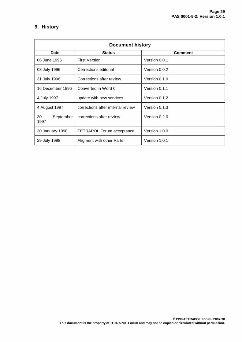
9. History
Document historyDate Status Comment
06 June 1996 First Version Version 0.0.1
03 July 1996 Corrections editorial Version 0.0.2
31 July 1996 Corrections after review Version 0.1.0
16 December 1996 Converted in Word 6 Version 0.1.1
4 July 1997 update with new services Version 0.1.2
4 August 1997 corrections after internal review Version 0.1.3
30 September1997
corrections after review Version 0.2.0
30 January 1998 TETRAPOL Forum acceptance Version 1.0.0
29 July 1998 Aligment with other Parts Version 1.0.1