Embed Size (px)
Citation preview

TG 132: Use of Image
Registration and Fusion in RT
Kristy K Brock, PhD, DABR, FAAPM
Associate Professor
Department of Radiation Oncology, University of Michigan
Chair, AAPM TG 132: Image Registration and Fusion

Acknowledgements & Conflict of Interest
• AAPM Task Group 132 Members
• I have a licensing agreement for
deformable image registration technology
with RaySearch Laboratories.

Objectives
1. Describe how (deformable) image
registration algorithms work?
2. Describe techniques to commission
and validate image registration in the
clinic (TG 132 recommendations)
3. Illustrate the concepts with clinical
examples.

Techniques
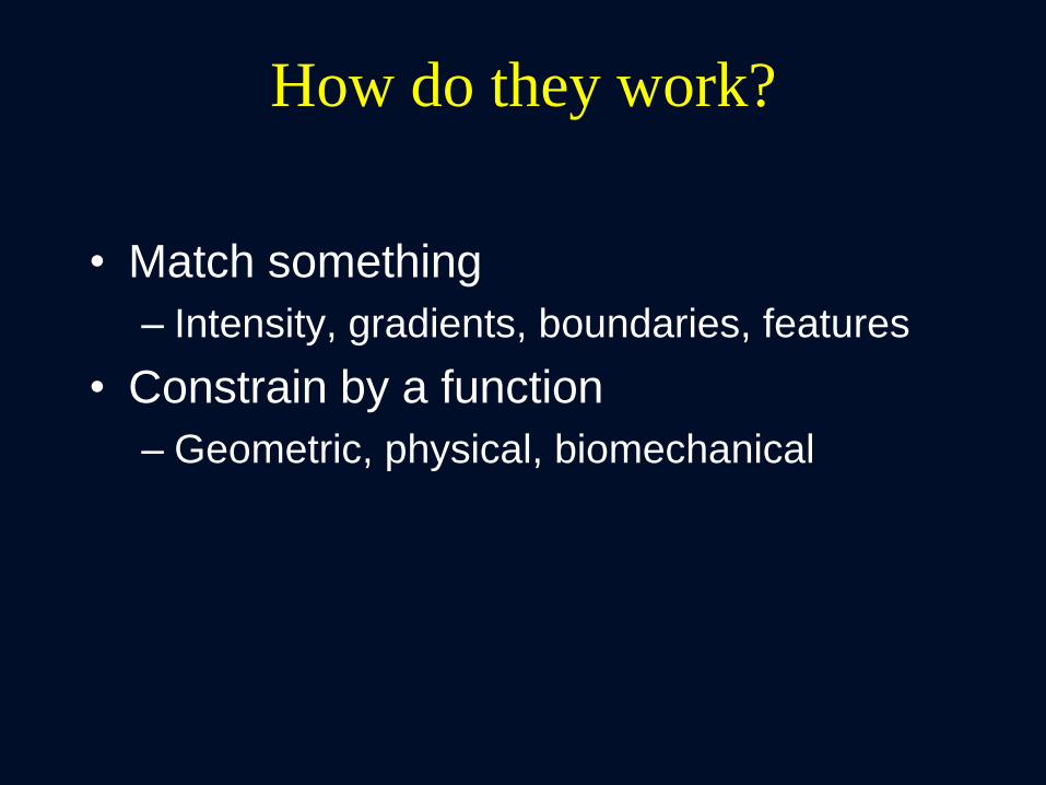
How do they work?
• Match something
– Intensity, gradients, boundaries, features
• Constrain by a function
– Geometric, physical, biomechanical

How do they work?
• Match something
– Intensity, gradients, boundaries, features
– What happens when the intensity correspondence
varies?
– What happens when the gradient isn’t there?
– What happens when the boundaries aren’t well
defined?
– What happens with the features aren’t visible?
• Constrain by a function
– Geometric, physical, biomechanical
– Can you rely on this model when the match above
is missing?

Why? Many Image Registration Techniques
Metric Transformation Optimization
Your Eye Translation Brain-power
Least Squares (Points) Translation + Rotation Simplex
Chamfer Matching
(surface matching)
Affine
(Translation + Rotation
+ scaling + shearing)
Gradient descent
Contour matching etc…
Mean Square Difference Spline (B-spline, Thin
plate spline)
Correlation Coefficient Physical (optical/fluid
flow, elastic body)
Mutual Information Biomechanical
Quick, Easy,
local
Surface-based
Manual or auto-
segmentation
Great for 4D CT
Good for same modality (x-ray), different
contrast/noise (CECT, CT, CBCT) Works for Multi-
Modality

Top 3 Similarity Metrics
• Sum of the Square Differences
• Mutual Information
• Contour Propagation

Sum of Squared Differences … subtract one image from the other
I I (I -I )2
CT2 CT1 CT2 CT1
CT = Difference
Image - CT1 CT2
Kessler / UM
Individual Intensity Distributions Sum of the Squares of
the Differences

This doesn’t usually make much sense
Not Zero
CT
= Difference
Image -
MR
Kessler / UM
I I CT MR
Individual Intensity Distributions
Sum of Squared Differences … subtract one image from the other

Mutual Information
• Maximise the mutual information
• Sensitivity of results: Vary the vector field and
evaluate the change in similarity metric
– Hub, et. al., IEEE TMI 2009
Marginal Entropies
H(A) H(B)
Joint Entropy
H(A,B)
Mutual Information,
I(A,B)

How Reliable is the Max MI?
• Actually, min -MI
dX
-MI
dX
-MI
Min –MI
Best Solution
Min –MI
Best Solution

Intensity Variation: Impact on CC/MSD
Clear intensity variation No relevant intensity
variation, noise/artifact
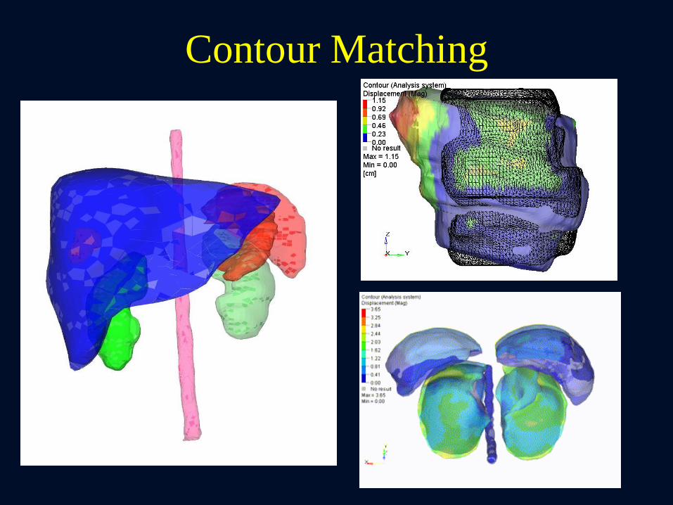
Contour Matching

Top 3 Regularizers
• Thin Plate Splines & B-Splines
– Weighted basis splines
• Flow/Optical
– Gradient driven with regularization
• Elastic/Biomechanical
– Material properties: compressibility and
stiffness
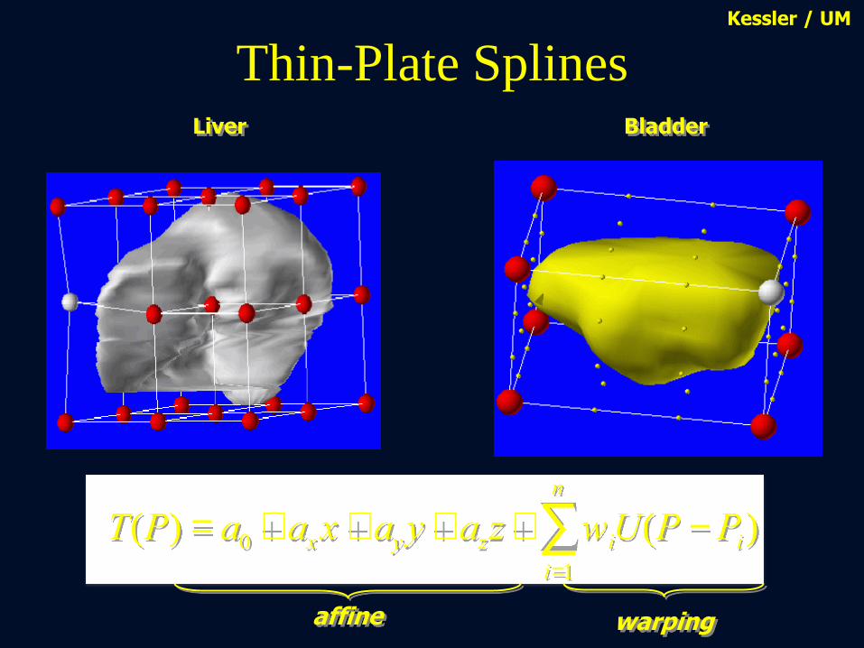
Thin-Plate Splines
T(P) = a0 + axx + ayy + azz + wiU(P -Pi)i=1
n
å
warping affine
Liver Bladder
Kessler / UM
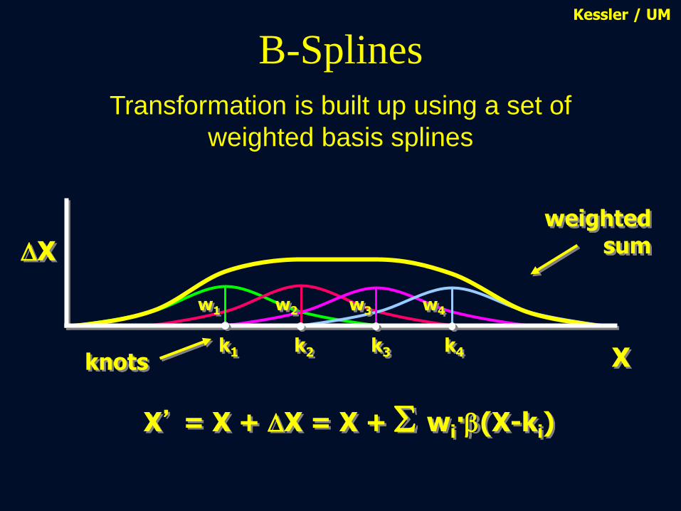
B-Splines
DX
X’ = X + DX = X + wi·b(X-ki)
knots X k1 k2 k3 k4
w2 w3 w4 w1
weighted sum
Kessler / UM
Transformation is built up using a set of
weighted basis splines

B-Splines
DX
knots X k1 k2 k3 k4
w1
w2
w3 w4
weighted sum
Kessler / UM
X’ = X + DX = X + wi·b(X-ki)
Transformation is built up using a set of
weighted basis splines

B-Splines Kessler / UM
X’ = X + DX = X + wi·b(X-ki)
Basis function has finite range

Parenchyma
(Tetra elements)
Exhale Image
Boundary Conditions
Finite Element Analysis
Inhale Image
Biomechanical Model
Surface Projection
Surface Surface Mesh
Contact Surface
Bronchial Tree
(Shell Elements)

Commissioning and QA
Preliminary recommendations from TG 132*
*pending approval from Science Council
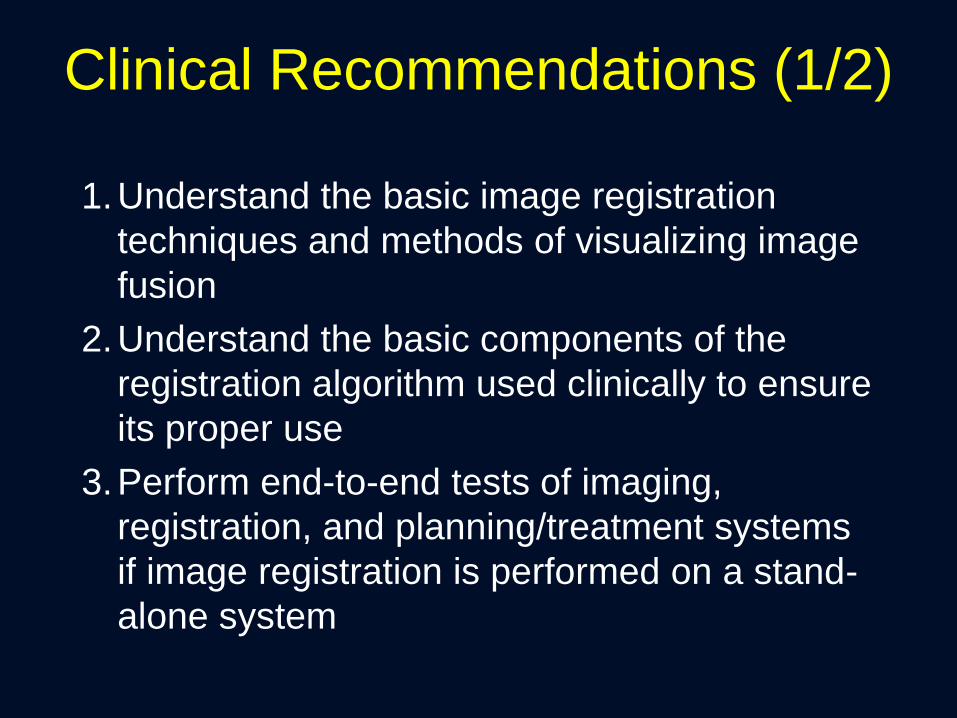
Clinical Recommendations (1/2)
1.Understand the basic image registration
techniques and methods of visualizing image
fusion
2.Understand the basic components of the
registration algorithm used clinically to ensure
its proper use
3.Perform end-to-end tests of imaging,
registration, and planning/treatment systems
if image registration is performed on a stand-
alone system

Clinical Recommendations (2/2)
4. Perform comprehensive commissioning of
image registration using the provided digital
phantom data (or similar data) as well as clinical
data from the user’s institution
5. Develop a request and report system to ensure
communication and documentation between all
users of image registration
6. Establish a patient specific QA practice for
efficient evaluation of image registration results
Commissioning and QA Understand the whole picture
Understand
fundamental
components of
algorithm

Understand the basic image registration
techniques and methods of visualizing
image fusion
How?
• TG report has basic information and
references
• AAPM Virtual Library
• Several books and review papers
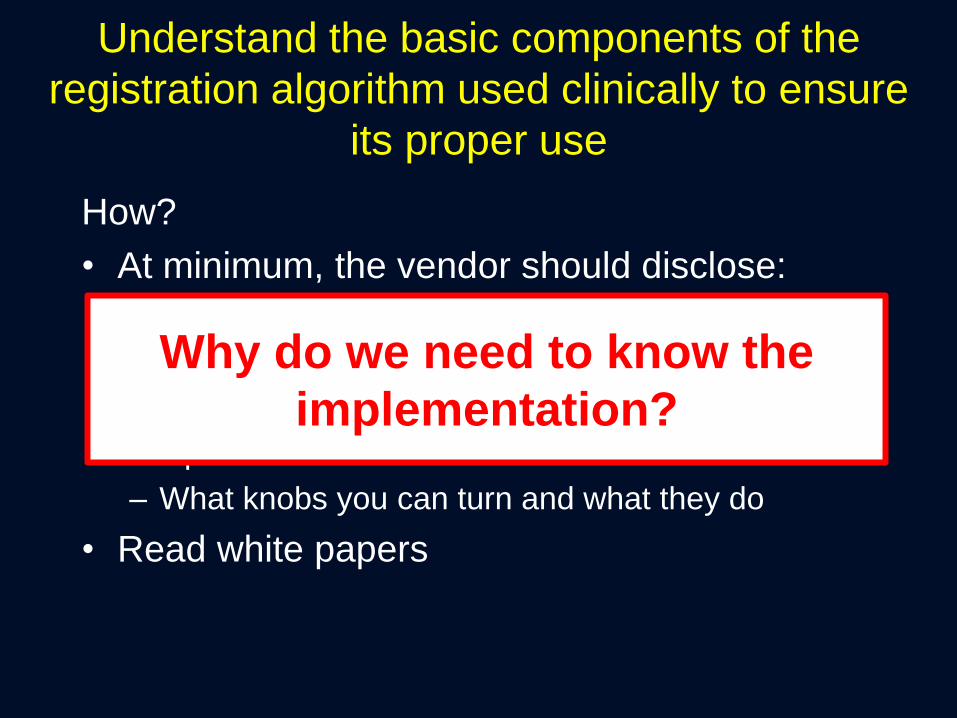
Understand the basic components of the
registration algorithm used clinically to ensure
its proper use
How?
• At minimum, the vendor should disclose:
– Similarity metric used
– Regularization used
– Transformation used
– Optimization method
– What knobs you can turn and what they do
• Read white papers
Why do we need to know the
implementation?

New method to validate
Deformable Image Registration
Control
(No Deformation)
Deformed
(27% Lateral Compression)
Deformable 3D Presage dosimeters
Slides Courtesy of Mark Oldham and Shiva Das

Dosimeter & Deformable Registration-based Dose
Accumulation: Dose Distributions
Field Displacements Deformed Dosimeter DVF-based
Accumulation
Field Shape Differences
Horizontal (Compression Axis) → 40% narrower to 175% wider
Vertical → 33% shorter to 50% taller
Slides Courtesy of Mark Oldham and Shiva Das
Caution must be used when
accumulating dose, especially in
regions of the image with
homogeneous intensity.

Distribution Coronal Axial Sagittal 3D γ3%/3mm
Measured,
Optical CT
DIR-predicted,
Biomechanical
Surface projection
96%1
(control)
1. Juang. IJROBP 2013;87(2): 414-421
2. M Velec, et al, PRO, 2015
91%2
Different DIR Algorithms have
Different Strengths and Weaknesses
DIR-predicted,
Intensity-based DIR 60%1

Commissioning and QA Understand the whole picture
Understand
fundamental
components of
algorithm
Phantom
approach to
understand
characteristics of
algorithm
implementation

Perform end-to-end tests of imaging, registration, and
planning/treatment systems if image registration is
performed on a stand-alone system
How? Any simple phantom or solid water
Why? It’s already mandated
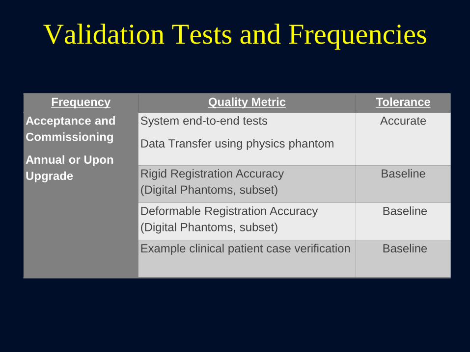
Validation Tests and Frequencies
Frequency Quality Metric Tolerance
Acceptance and
Commissioning
Annual or Upon
Upgrade
System end-to-end tests
Data Transfer using physics phantom
Accurate
Rigid Registration Accuracy
(Digital Phantoms, subset)
Baseline
Deformable Registration Accuracy
(Digital Phantoms, subset)
Baseline
Example clinical patient case verification Baseline

Why Virtual Phantoms
• Known attributes (volumes, offsets,
deformations, etc.)
• Testing standardization – we all are
using the same data
• Geometric phantoms – quantitative
validation
• Anthropomorphic – realistic and
quantitative
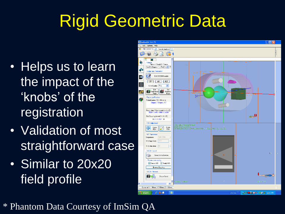
Rigid Geometric Data
• Helps us to learn
the impact of the
‘knobs’ of the
registration
• Validation of most
straightforward case
• Similar to 20x20
field profile
* Phantom Data Courtesy of ImSim QA
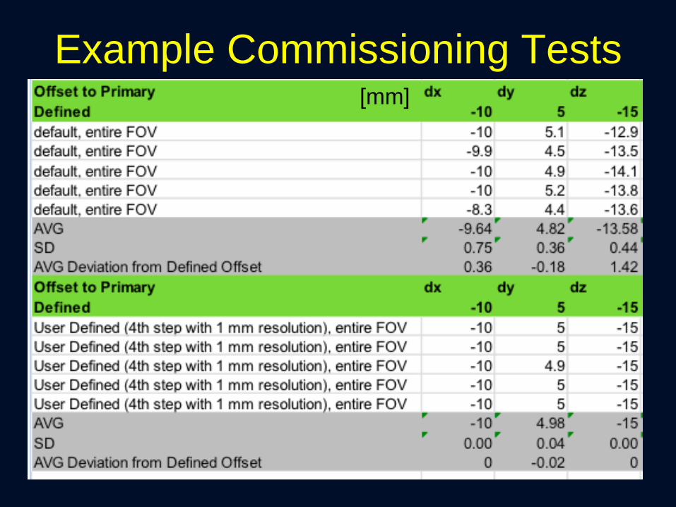
Example Commissioning Tests [mm]

Rigid Anatomical Phantom
• Multi-Modality
• Translation Offset
• 1 additional (simple)
layer of complexity

Deformable Phantom
Commissioning Procedure:
• Run Deformable Image Registration
• Export DICOM Deformation Vector Field
(DVF)
• Pseudo code provided to compare
known DVF with exported DVF
• Target: 95% of voxels within 2 mm, max
error less than 5 mm
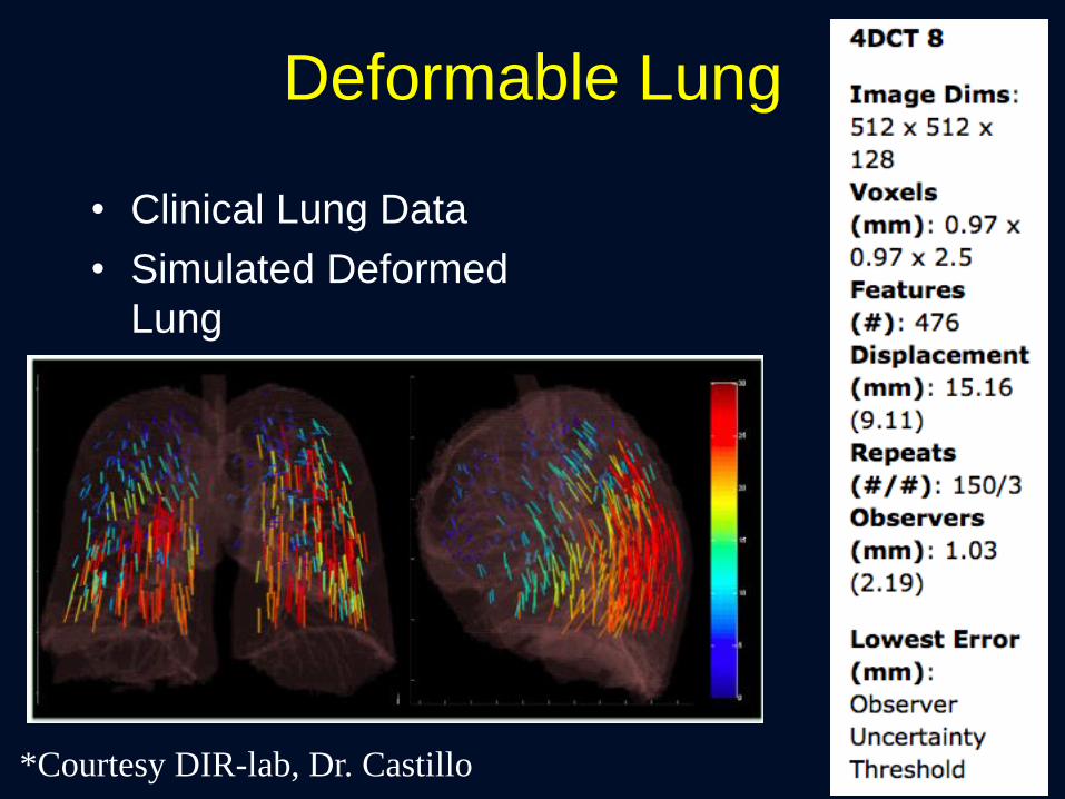
Deformable Lung
• Clinical Lung Data
• Simulated Deformed
Lung
*Courtesy DIR-lab, Dr. Castillo
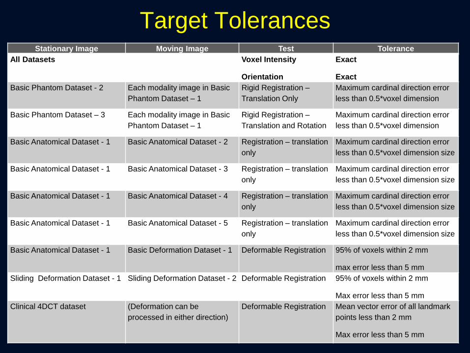
Target Tolerances Stationary Image Moving Image Test Tolerance
All Datasets Voxel Intensity
Orientation
Exact
Exact
Basic Phantom Dataset - 2 Each modality image in Basic
Phantom Dataset – 1
Rigid Registration –
Translation Only
Maximum cardinal direction error
less than 0.5*voxel dimension
Basic Phantom Dataset – 3 Each modality image in Basic
Phantom Dataset – 1
Rigid Registration –
Translation and Rotation
Maximum cardinal direction error
less than 0.5*voxel dimension
Basic Anatomical Dataset - 1 Basic Anatomical Dataset - 2 Registration – translation
only
Maximum cardinal direction error
less than 0.5*voxel dimension size
Basic Anatomical Dataset - 1 Basic Anatomical Dataset - 3 Registration – translation
only
Maximum cardinal direction error
less than 0.5*voxel dimension size
Basic Anatomical Dataset - 1 Basic Anatomical Dataset - 4 Registration – translation
only
Maximum cardinal direction error
less than 0.5*voxel dimension size
Basic Anatomical Dataset - 1 Basic Anatomical Dataset - 5 Registration – translation
only
Maximum cardinal direction error
less than 0.5*voxel dimension size
Basic Anatomical Dataset - 1 Basic Deformation Dataset - 1 Deformable Registration 95% of voxels within 2 mm
max error less than 5 mm
Sliding Deformation Dataset - 1 Sliding Deformation Dataset - 2 Deformable Registration 95% of voxels within 2 mm
Max error less than 5 mm
Clinical 4DCT dataset
(Deformation can be
processed in either direction)
Deformable Registration Mean vector error of all landmark
points less than 2 mm
Max error less than 5 mm

Commissioning and QA
Understand the whole picture
Understand
fundamental
components of
algorithm
Phantom
approach to
understand
characteristics of
algorithm
implementation Quantitative
Validation of
Clinical Images

What Tools Do we Have?
• Visual Verification: Excellent tool for
established techniques.
– Not enough for commissioning!

Quantitative Validation Techniques
• Landmark Based
– Does the registration map a landmark on Image A
to the correct position on Image B?
– Target Registration Error (TRE)
• Contour Based
– Does the registration map the contours onto the
new image correctly?
– Dice Similarity Coefficient (DSC)
– Mean Distance to Agreement (MDA)
• Digital/Physical Phantoms
– Compare known motion with registration results

Landmark Based (TRE)
• Reproducibility of point identification is sub-voxel – Gross errors
– Quantification of local accuracy within the target
– Increasing the number increases the overall volume quantification
• Manual technique
• Can identify max errors CT: 512x512x152; 0.09 cm in plane, 0.25 cm
slice; GE scanner; 4D CT with Varian RPM
TRE
A
A’ B

That sounds great! Is that enough?

Accuracy of Points
X
X
X
1 cm
RMS = 0.3 mm

Points Don’t Tell the Whole Story
X
X
X
1 cm

Algorithm 2
Algorithm 1
Accuracy of Contours
Actual Exhale Modeled Exhale
Modeled Exhale Error
102 Bronchial
Bifs
TRE: 3.7 mm
TRE: 8.0 mm
Inhal
e
DSC > 0.9
DSC > 0.9

Commissioning and QA
Understand the whole picture
Understand
fundamental
components of
algorithm
Phantom
approach to
understand
characteristics of
algorithm
implementation Quantitative
Validation of
Clinical Images Documentation
and Evaluation in
Clinical
Environment

Request
• Clear identification of the image set(s) to be
registered
– Identification of the primary (e.g. reference) image
geometry
• An understanding of the local region(s) of
importance
• The intended use of the result
– Target delineation
• Techniques to use (deformable or rigid)
• The accuracy required for the final use

Report
• Identify actual images used
• Indicate the accuracy of registration for local
regions of importance and anatomical
landmarks
– Identify any critical inaccuracies to alert the user
• Verify acceptable tolerances for use
• Techniques used to perform registration
• Fused images in report with annotations
• Documentation from system used for fusion

Clinical Example
DIR for Multi-Modality
Planning
• Accuracy required: voxel
level
• Uncertainties create a
systematic error that
propagates throughout
the treatment
?
CT – no contrast
MRI – with contrast
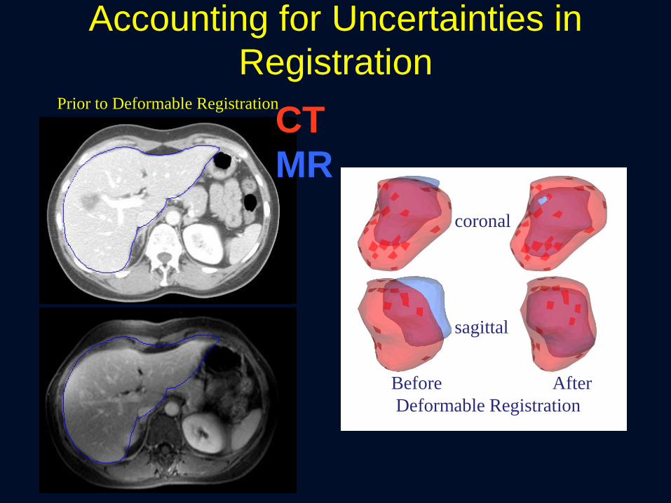
coronal
sagittal
Prior to Deformable Registration
Before After
Deformable Registration
CT
MR
Accounting for Uncertainties in
Registration

Accounting for Uncertainties in
Registration
X
GTV (defined on MR,
mapped to CT for Tx)
Region of CT-defined
GTV that is missed
• Assess uncertainty around GTV
• Add margin around GTV definition to
account for uncertainty when required
Prior to Deformable Registration
CT
MR

Clinical Impact of Dose Accumulation
Velec, IJROBP 2012
•30 patients
•70% of patients have acc
dose deviations (≥5%) from
the static plan
Swaminath, IJROBP, in press
•81 patients, 142 liver mets
•accGTV dose is a better
predictor of TTLP compared
to minPTV dose for liver
metastases SBRT
Dose Accumulation
Tx
EXH
INH

Establish a patient specific QA practice for
efficient evaluation of image registration results
Why?
• At this point we are still understanding
how the the registration is performing on
different types of patients
How?
• Visual Verification
• Spot checks of landmarks
• Boundary comparison
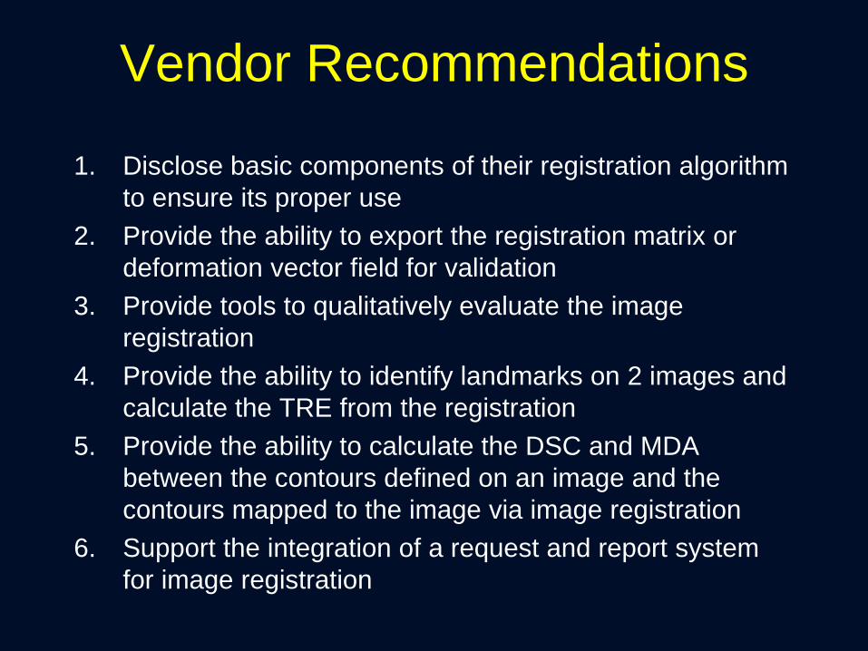
Vendor Recommendations
1. Disclose basic components of their registration algorithm
to ensure its proper use
2. Provide the ability to export the registration matrix or
deformation vector field for validation
3. Provide tools to qualitatively evaluate the image
registration
4. Provide the ability to identify landmarks on 2 images and
calculate the TRE from the registration
5. Provide the ability to calculate the DSC and MDA
between the contours defined on an image and the
contours mapped to the image via image registration
6. Support the integration of a request and report system
for image registration
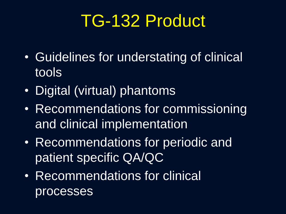
TG-132 Product
• Guidelines for understating of clinical
tools
• Digital (virtual) phantoms
• Recommendations for commissioning
and clinical implementation
• Recommendations for periodic and
patient specific QA/QC
• Recommendations for clinical
processes

Summary
• Deformable registration is a powerful tool that
can help us to integrate multi-modality images,
understand motion and anatomical changes,
and compute an improved estimate of the
delivered dose
• With power comes responsibility… we must
commission the system prior to use,
understand the limitations, and communicate its
proper use to clinicians, dosimetrists,
therapists, and others
• TG 132 can help to provide tools, but the
individuality of clinical workflows requires
individual tests