Embed Size (px)
Citation preview

Inmak 2000 Ltd10 Dounav Str.2900 Goce DelchevBULGARIA
Phone: +359 751 60979Cell: +359 888 244 641 +359 885 875 987Fax: +359 751 60978
E-mail: [email protected]: [email protected]
www.inmak2000bg.com
Challange the distance with
Inmakthe antenna company
PRODUCT CATALOGUE 2010Base Station Antennas
cover.v2.CMYK.indd 2-3 09.9.2007 ã. 19:16:11

Base Station A
ntennas380-470 MHzAC70 39AC70-D 40AC5-3G 41AC5-5G 42AC5-7G 43AC5-10G 44AC5-12G 45BA70-1G 46BA70-3G 47BA70-5G 48BA70-7G 49ASKI 450 50BD70-3G 51BD70-6G 52
820-960 MHzAC6-10G 53AC6-12G 54BA90-1G 55BA90-3G 56
1200 MHzAC1.2-7G 57AC1.2-11G 58BA1.2-6G 59ACP1.2-24G 60
2400 MHzBA2.4-6G 61BA2.4-12G 62AC2.4-11G 63ACP2.4-24G 64
5800 MHzBA5.8-12G 65ACP5.8-24G 66
CONTENTS26-108 MHzAC-CB 2AC-4 3AC-4 ST 4AC50-D-O 5AC50-D3G-O 6AC50-D5G-O 7AC-8 8AC80-D 9AC80-D3G 10AC80-D5G 11AC-4F 12BA4-1G 13
118-136 MHzAC-2 AIR 14ASKI 120 15AC-D AIR 16BA2-1G AIR 17
134-175 MHzAC-2 18AC-2F 19AC-D 20AC-D3G 21AC-D6G 22AC-D8G 23BA2-1G 24BA2-3G 25BA2-5G 26ASKI 160 27B-2R 28BD2-3G 29BD2-6G 30
300-350 MHzAC3-D 31AC3-D3G 32AC3-D6G 33AC3-D8G 34BA3-1G 35ASKI 300 36BD3-3G 37BD3-6G 38

TYPICAL SWR CURVE
SW
R
freq. MHz
1.0
2.0
1.5
1 MHz Frequency Band
For drawings, technical data or samples, contact our engeneers. Specifications subject to change. Consult Inmak 2000 Ltd. for latest specifications.
2 Product catalog | Inmak 2000
spec
ification
s
BA
SE
STA
TIO
N A
NT
EN
NA
S
AC-CB
AC-CB is an aluminum ground-plane antenna of the triple-leg type. The antenna can be easily installed where no soldering is required. The antenna requires no adjustment. The antenna comprises an aluminum GP-head, one aluminum radiator and three aluminum radials.
3-radial CB Base Antenna
Type GROUND PLANE
ELECTRICALFrequency Range 26-28 MHz
Band width 1 MHz
SWR < 1.2
Gain 0 dBd (2.15 dBi)
Impedance 50 Ω
Max. Power 300 W
Polarization Vertical
Antistatic protection N/A
Connector UHF (female)
MECHANICALLength 5.5 m max.
Weight 1.7 kg
Mounting 27-50 mm mast tube
Material aluminumWind Load 150 km/h
ORDERING DESIGNATIONSWhen ordering, please, specify an exact frequency.

TYPICAL SWR CURVE
SW
R
freq. MHz
1.0
2.0
1.5
1.5 MHz Frequency Band
Product catalog | Inmak 2000 3For drawings, technical data or samples, contact our engeneers. Specifications subject to change. Consult Inmak 2000 Ltd. for latest specifications.
spec
ification
s
BA
SE
STATIO
N A
NT
EN
NA
S
AC-43-radial Base Station Antenna for the 30-66 MHz Band
AC-4 is an aluminum ground-plane antenna of the triple-leg type. The antenna can be easily installed where no soldering is required. The antenna requires no adjustment. The antenna comprises an aluminum GP-head, one aluminum radiator and three aluminum radials.
Type GROUND PLANE
ELECTRICALFrequency Range 30-66 MHz
Band width 1.5 MHz
SWR < 1.2
Gain 0 dBd (2.15 dBi)
Impedance 50 Ω
Max. Power 300 W
Polarization Vertical
Antistatic protection N/A
Connector UHF (female) or N (female)
MECHANICALLength 5.5 m max.
Weight 1.5 kg
Mounting 27-40 mm mast tube
Material aluminumWind Load 150 km/h
ORDERING DESIGNATIONSWhen ordering, please, specify an exact frequency.

TYPICAL SWR CURVE
SW
R
freq. MHz
1.0
2.0
1.5
1.5 MHz Frequency Band
For drawings, technical data or samples, contact our engeneers. Specifications subject to change. Consult Inmak 2000 Ltd. for latest specifications.
4 Product catalog | Inmak 2000
spec
ification
s
BA
SE
STA
TIO
N A
NT
EN
NA
S
AC-4 ST3-radial Base Station Antenna for the 30-66 MHz Band
AC-4 ST is a steel ground-plane antenna of the triple-leg type. The antenna can be easily installed where no soldering is required. The antenna requires no adjustment. The antenna comprises an aluminum GP-head, one steel radiator and three steel radials.
Type GROUND PLANE
ELECTRICALFrequency Range 30-66 MHz
Band width 1.5 MHz
SWR < 1.2
Gain 0 dBd (2.15 dBi)
Impedance 50 Ω
Max. Power 300 W
Polarization Vertical
Antistatic protection N/A
Connector UHF (female) or N (female)
MECHANICALLength 5.5 m max.
Weight 1.6 kg
Mounting 27-40 mm mast tube
Material stainless steelWind Load 150 km/h
ORDERING DESIGNATIONSWhen ordering, please, specify an exact frequency.

TYPICAL SWR CURVE
SW
R
freq. MHz
1.0
2.0
1.5
RADIATION PATTERN (E-PLANE) RADIATION PATTERN (H-PLANE)+90°
-90°
+60°+30°
0°
+30°+60°
-60°-30° -30°-60°
0°
0°
180°
330°300°
90°
60°30°
210°240° 120°150°
270°-6+3 0 -3 -9 0-9 -6 -3 +3 -6+3 0 -3 -9 0-9 -6 -3 +3
48 AC50-D-O 66
Product catalog | Inmak 2000 5For drawings, technical data or samples, contact our engeneers. Specifications subject to change. Consult Inmak 2000 Ltd. for latest specifications.
spec
ification
s
BA
SE
STATIO
N A
NT
EN
NA
S
AC50-D-O
Single, 0 dBd open dipole incorporating a balun optimized for wide band width and accurate matching. The dipole element has been constructed in high quality aluminum alloys to prevent corrosion. The antenna is terminated with N (female) connector. A mast clamp is provided for mounting on 27-50 mm diameter mast tube.
Type YAGI
ELECTRICALFrequency Range 48-66 MHz
Band width 19 MHz
SWR < 1.5
Gain 0 dBd (2.15 dBi)
Impedance 50 Ω
Max. Power 150 W
Polarization Vertical; Horizontal
Antistatic protection N/A
Connector N (female)
MECHANICALMounting 27-50 mm mast tube
Material aluminum
Wind Load 150 km/h
ORDERING DESIGNATIONSType FrequencyAC50-D-O 48-66 MHz
Open Dipole for the 48-66 MHz Band

TYPICAL SWR CURVE
SW
R
freq. MHz
1.0
2.0
1.5
RADIATION PATTERN (E-PLANE) RADIATION PATTERN (H-PLANE)+90°
-90°
+60°+30°
0°
+30°+60°
-60°-30° -30°-60°
0°
0°
180°
330°300°
90°
60°30°
210°240° 120°150°
270°-6+3 0 -3 -9 0-9 -6 -3 +3 -6+3 0 -3 -9 0-9 -6 -3 +3
4856
AC50-D3G-O/lAC50-D3G-O/h
5866
For drawings, technical data or samples, contact our engeneers. Specifications subject to change. Consult Inmak 2000 Ltd. for latest specifications.
6 Product catalog | Inmak 2000
BA
SE
STA
TIO
N A
NT
EN
NA
S
AC50-D3G-O
This is a 2-element Yagi antenna with 3 dBd Gain. This Yagi incorporates baluns optimized for wide bandwidth and accurate matching. The antenna is terminated with N (female) connector. Radiating elements, supporting booms and adjoining metal castings are constructed in high-quality-aluminum alloys to prevent corrosion. A mast clamp is provided for mounting on 27-50 mm diameter mast tube.
Type YAGI
ELECTRICALFrequency Range 48-66 MHz
Band width 10 MHz
SWR < 1.5
Gain 3 dBd (5.15 dBi)
Impedance 50 Ω
Max. Power 150 W
Polarization Vertical; Horizontal
Front to back ratio 12 dB
Antistatic protection N/A
Connector N (female)
MECHANICALLength 1.8 m
Weight 5 kg
Mounting 27-50 mm mast tube
Material aluminum
Wind Load 150 km/h
ORDERING DESIGNATIONSType FrequencyAC50-D3G-O/l 48-58 MHz
AC50-D3G-O/h 56-66 MHz
2-element Yagi Antenna for the 48-66 MHz Band
spec
ification
s

TYPICAL SWR CURVE
SW
R
freq. MHz
1.0
2.0
1.5
RADIATION PATTERN (E-PLANE) RADIATION PATTERN (H-PLANE)+90°
-90°
+60°+30°
0°
+30°+60°
-60°-30° -30°-60°
0°
0°
180°
330°300°
90°
60°30°
210°240° 120°150°
270°
5 MHz Frequency Band
-3+6 +3 0 -6 +3-6 -3 0 +6 -3+6 +3 0 -6 +3-6 -3 0 +6
SW
R
Product catalog | Inmak 2000 7For drawings, technical data or samples, contact our engeneers. Specifications subject to change. Consult Inmak 2000 Ltd. for latest specifications.
spec
ification
s
BA
SE
STATIO
N A
NT
EN
NA
S
AC50-D5G-O
This is a 3-element Yagi antenna with 5 dBd Gain. The antenna is terminated with N (female) connector. Radiating elements, supporting booms and adjoining metal castings are constructed in high-quality-aluminum alloys to prevent corrosion. A mast clamp is provided for mounting on 27-50 mm diameter mast tube.
Type YAGI
ELECTRICALFrequency Range 48-66 MHz
Band width 5 MHz
SWR < 1.5
Gain 5 dBd (7.15 dBi)
Impedance 50 Ω
Max. Power 150 W
Polarization Vertical; Horizontal
Front to back ratio 16 dB
Antistatic protection N/A
Connector N (female)
MECHANICALLength 2.5 m
Weight 5.5 kg
Mounting 27-50 mm mast tube
Material aluminum
Wind Load 150 km/h
ORDERING DESIGNATIONSWhen ordering, please, specify an exact frequency.
3-element Yagi Antenna for the 48-66 MHz Band
TYPICAL SWR CURVE
SW
R
freq. MHz
1.0
2.0
1.5
2 MHz Frequency Band
For drawings, technical data or samples, contact our engeneers. Specifications subject to change. Consult Inmak 2000 Ltd. for latest specifications.
8 Product catalog | Inmak 2000
spec
ification
s
BA
SE
STA
TIO
N A
NT
EN
NA
S
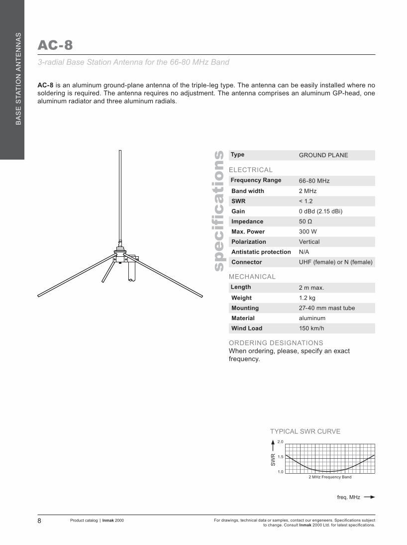
AC-8
AC-8 is an aluminum ground-plane antenna of the triple-leg type. The antenna can be easily installed where no soldering is required. The antenna requires no adjustment. The antenna comprises an aluminum GP-head, one aluminum radiator and three aluminum radials.
3-radial Base Station Antenna for the 66-80 MHz Band
Type GROUND PLANE
ELECTRICALFrequency Range 66-80 MHz
Band width 2 MHz
SWR < 1.2
Gain 0 dBd (2.15 dBi)
Impedance 50 Ω
Max. Power 300 W
Polarization Vertical
Antistatic protection N/A
Connector UHF (female) or N (female)
MECHANICALLength 2 m max.
Weight 1.2 kg
Mounting 27-40 mm mast tube
Material aluminum
Wind Load 150 km/h
ORDERING DESIGNATIONSWhen ordering, please, specify an exact frequency.

TYPICAL SWR CURVE
SW
R
freq. MHz
1.0
2.0
1.5
RADIATION PATTERN (E-PLANE) RADIATION PATTERN (H-PLANE)+90°
-90°
+60°+30°
0°
+30°+60°
-60°-30° -30°-60°
0°
0°
180°
330°300°
90°
60°30°
210°240° 120°150°
270°-6+3 0 -3 -9 0-9 -6 -3 +3 -6+3 0 -3 -9 0-9 -6 -3 +3
66 AC80-D 85
Product catalog | Inmak 2000 9For drawings, technical data or samples, contact our engeneers. Specifications subject to change. Consult Inmak 2000 Ltd. for latest specifications.
spec
ification
s
BA
SE
STATIO
N A
NT
EN
NA
S
AC80-DCenter-Fed-Folded Dipole for the 66-85 MHz Band
Single, 0 dBd folded dipole incorporating a balun optimized for wide bandwidth and accurate matching. The entire balun unit and feeder terminations are completely sealed in a polyethylene (PET) moulding ensuring permanent waterproof connections. The dipole element, the supporting boom and the adjoining metal castings have been constructed in high quality aluminum alloys to prevent corrosion. All metal parts are DC-grounded. The antenna is supplied with clamp for mounting on 27-50 mm diameter mast tubes.
Type Dipole
ELECTRICALFrequency Range 66-85 MHz
Band width 19 MHz
SWR < 1.5
Gain 0 dBd (2.15 dBi)
Impedance 50 Ω
Max. Power 150 W
Polarization Vertical; Horizontal
Antistatic protection DC-grounded (Connector shows a DC-short)
Connector N (female)
MECHANICALWeight 3.5 kg
Mounting 27-50 mm mast tube
Material aluminum
Wind Load 150 km/h
ORDERING DESIGNATIONSType FrequencyAC80-D 66-85 MHz

TYPICAL SWR CURVE
SW
R
freq. MHz
1.0
2.0
1.5
RADIATION PATTERN (E-PLANE) RADIATION PATTERN (H-PLANE)+90°
-90°
+60°+30°
0°
+30°+60°
-60°-30° -30°-60°
0°
0°
180°
330°300°
90°
60°30°
210°240° 120°150°
270°-6+3 0 -3 -9 0-9 -6 -3 +3 -6+3 0 -3 -9 0-9 -6 -3 +3
6675
AC80-D3G/lAC80-D3G/h
7685
For drawings, technical data or samples, contact our engeneers. Specifications subject to change. Consult Inmak 2000 Ltd. for latest specifications.
10 Product catalog | Inmak 2000
spec
ification
s
BA
SE
STA
TIO
N A
NT
EN
NA
S
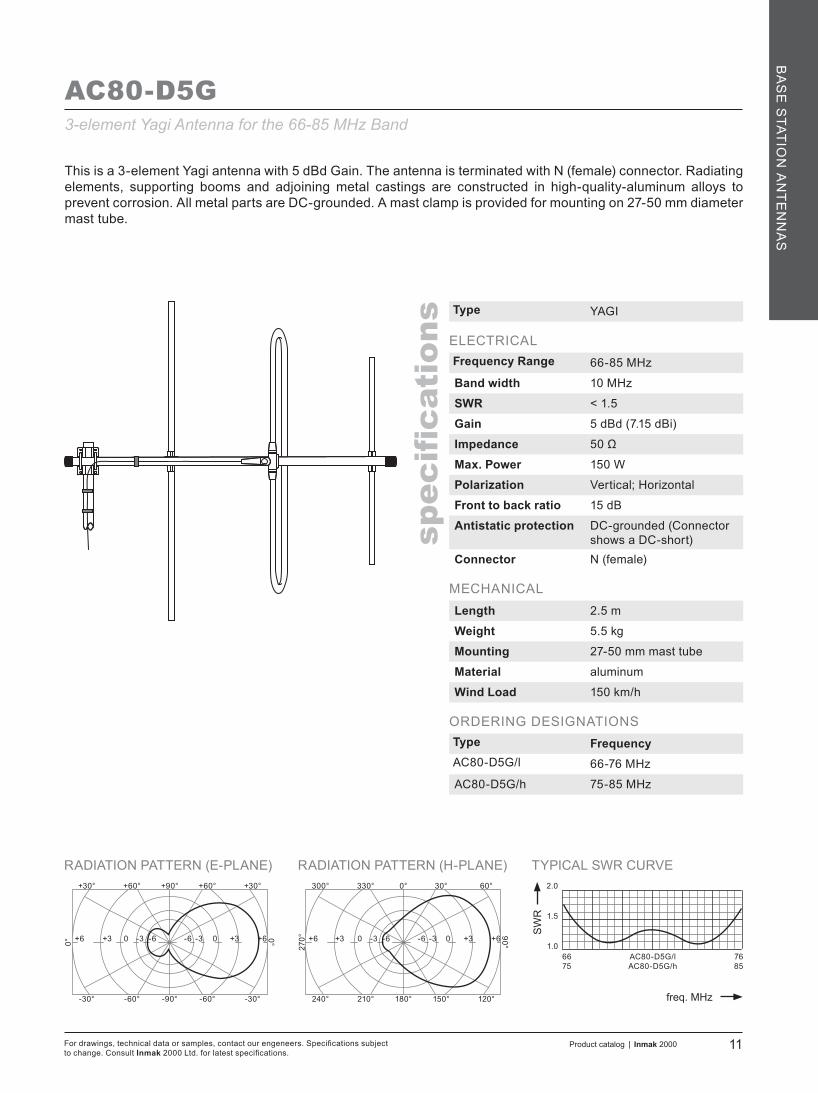
AC80-D3G
This is a 2-element Yagi antenna with 3 dBd Gain. The entire balun unit and feeder cable inlet are completely sealed in a polyethylene (PET) moulding ensuring permanent waterproof connections. The antenna is terminated with N (female) connector. Radiating elements, supporting booms and adjoining metal castings are constructed in high-quality-aluminum alloys to prevent corrosion. All metal parts are DC-grounded. A mast clamp is provided for mounting on 27-50 mm diameter mast tube.
Type YAGI
ELECTRICALFrequency Range 66-85 MHz
Band width 10 MHz
SWR < 1.5
Gain 3 dBd (5.15 dBi)
Impedance 50 Ω
Max. Power 150 W
Polarization Vertical; Horizontal
Front to back ratio 12 dB
Antistatic protection DC-grounded (Connector shows a DC-short)
Connector N (female)
MECHANICALLength 1.8 m
Weight 5 kg
Mounting 27-50 mm mast tube
Material aluminum
Wind Load 150 km/h
ORDERING DESIGNATIONSType FrequencyAC80-D3G/l 66-76 MHz
AC80-D3G/h 75-85 MHz
2-element Yagi Antenna for the 66-85 MHz Band
TYPICAL SWR CURVE
SW
R
freq. MHz
1.0
2.0
1.5
RADIATION PATTERN (E-PLANE) RADIATION PATTERN (H-PLANE)+90°
-90°
+60°+30°
0°
+30°+60°
-60°-30° -30°-60°
0°
0°
180°
330°300°
90°
60°30°
210°240° 120°150°
270°
6675
AC80-D5G/lAC80-D5G/h
7685
-3+6 +3 0 -6 +3-6 -3 0 +6 -3+6 +3 0 -6 +3-6 -3 0 +6
Product catalog | Inmak 2000 11For drawings, technical data or samples, contact our engeneers. Specifications subject to change. Consult Inmak 2000 Ltd. for latest specifications.
spec
ification
s
BA
SE
STATIO
N A
NT
EN
NA
S
AC80-D5G
This is a 3-element Yagi antenna with 5 dBd Gain. The antenna is terminated with N (female) connector. Radiating elements, supporting booms and adjoining metal castings are constructed in high-quality-aluminum alloys to prevent corrosion. All metal parts are DC-grounded. A mast clamp is provided for mounting on 27-50 mm diameter mast tube.
Type YAGI
ELECTRICALFrequency Range 66-85 MHz
Band width 10 MHz
SWR < 1.5
Gain 5 dBd (7.15 dBi)
Impedance 50 Ω
Max. Power 150 W
Polarization Vertical; Horizontal
Front to back ratio 15 dB
Antistatic protection DC-grounded (Connector shows a DC-short)
Connector N (female)
MECHANICALLength 2.5 m
Weight 5.5 kg
Mounting 27-50 mm mast tube
Material aluminum
Wind Load 150 km/h
ORDERING DESIGNATIONSType FrequencyAC80-D5G/l 66-76 MHz
AC80-D5G/h 75-85 MHz
3-element Yagi Antenna for the 66-85 MHz Band

TYPICAL SWR CURVE
SW
R
freq. MHz
1.0
2.0
1.5
1.5 MHz Frequency Band
For drawings, technical data or samples, contact our engeneers. Specifications subject to change. Consult Inmak 2000 Ltd. for latest specifications.
12 Product catalog | Inmak 2000
spec
ification
s
BA
SE
STA
TIO
N A
NT
EN
NA
S
AC-4F
Type GROUND PLANE
ELECTRICALFrequency Range 50-88 MHz
Band width 1.5 MHz
SWR < 1.2
Gain 0 dBd (2.15 dBi)
Impedance 50 Ω
Max. Power 300 W
Polarization Vertical
Antistatic protection N/A
Connector UHF (female) or N (female)
MECHANICALLength 2.5 m max.
Weight 3.5 kg
Mounting 27-50 mm mast tube
Material
Radiator: aluminum or stainless steel in a fiberglass tubeRadials: aluminum or stainless steelMounting bracket: aluminum
Wind Load 150 km/h
ORDERING DESIGNATIONSWhen ordering, please, specify an exact frequency.
Coaxial Ground Plane Antenna for the 50-88 MHz Band
AC-4F is a fiberglass ground plane antenna of the triple-leg type. The antenna comprises an aluminum GP-head, one coaxial-fiberglass radiator and three stainless-steel radials. The construction of the mount makes it possible to lead the cable either inside or along the outside of the mast tube. AC-4F is made of high-quality materials and will endure for years where no maintenance is required.
TYPICAL SWR CURVE
SW
R
freq. MHz
1.0
2.0
1.5
MULTI-PURPOSE MOUNTING BRACKET RADIATION PATTERN (E-PLANE)0°
180°
330°300°
90°
60°30°
210°240° 120°150°
270° -90 -3 -6 -12 -3-12 -9 -6 0
44566677
BA4-1G/lBA4-1G/mlBA4-1G/mhBA4-1G/h
55657688
Product catalog | Inmak 2000 13For drawings, technical data or samples, contact our engeneers. Specifications subject to change. Consult Inmak 2000 Ltd. for latest specifications.
spec
ification
s
BA
SE
STATIO
N A
NT
EN
NA
S
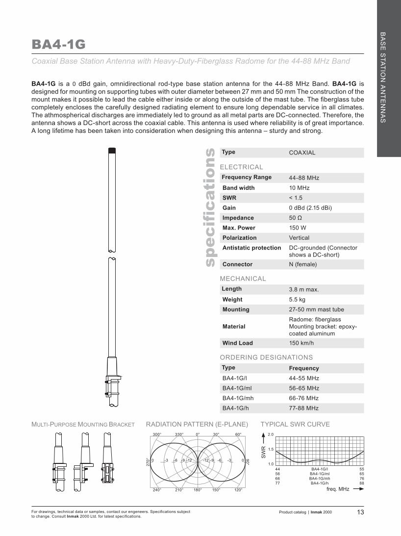
BA4-1G
BA4-1G is a 0 dBd gain, omnidirectional rod-type base station antenna for the 44-88 MHz Band. BA4-1G is designed for mounting on supporting tubes with outer diameter between 27 mm and 50 mm The construction of the mount makes it possible to lead the cable either inside or along the outside of the mast tube. The fiberglass tube completely encloses the carefully designed radiating element to ensure long dependable service in all climates. The athmospherical discharges are immediately led to ground as all metal parts are DC-connected. Therefore, the antenna shows a DC-short across the coaxial cable. This antenna is used where reliability is of great importance. A long lifetime has been taken into consideration when designing this antenna – sturdy and strong.
Type COAXIAL
ELECTRICALFrequency Range 44-88 MHz
Band width 10 MHz
SWR < 1.5
Gain 0 dBd (2.15 dBi)
Impedance 50 Ω
Max. Power 150 W
Polarization Vertical
Antistatic protection DC-grounded (Connector shows a DC-short)
Connector N (female)
MECHANICALLength 3.8 m max.
Weight 5.5 kg
Mounting 27-50 mm mast tube
MaterialRadome: fiberglassMounting bracket: epoxy-coated aluminum
Wind Load 150 km/h
ORDERING DESIGNATIONSType FrequencyBA4-1G/l 44-55 MHz
BA4-1G/ml 56-65 MHz
BA4-1G/mh 66-76 MHz
BA4-1G/h 77-88 MHz
Coaxial Base Station Antenna with Heavy-Duty-Fiberglass Radome for the 44-88 MHz Band

TYPICAL SWR CURVE
SW
R
freq. MHz
1.0
2.0
1.5
3 MHz Frequency Band
For drawings, technical data or samples, contact our engeneers. Specifications subject to change. Consult Inmak 2000 Ltd. for latest specifications.
14 Product catalog | Inmak 2000
spec
ification
s
BA
SE
STA
TIO
N A
NT
EN
NA
S
AC-2 AIR
AC-2 AIR is an aluminum ground-plane antenna of the triple-leg type. The antenna can be easily installed where no soldering is required. The antenna requires no adjustment. The antenna comprises an aluminum GP-head, one aluminum radiator and three aluminum radials.
Type GROUND PLANE
ELECTRICALFrequency Range 118-136 MHz
Band width 3 MHz
SWR < 1.2
Gain 0 dBd (2.15 dBi)
Impedance 50 Ω
Max. Power 300 W
Polarization Vertical
Antistatic protection N/A
Connector UHF (female) or N (female)
MECHANICALLength 1.5 m max.
Weight 1.2 kg
Mounting 27-40 mm mast tube
Material aluminumWind Load 150 km/h
ORDERING DESIGNATIONSWhen ordering, please, specify an exact frequency.
3-radial Base Station Antenna for the 118-136 MHz Band

TYPICAL SWR CURVE
SW
R
freq. MHz
1.0
2.0
1.5
MULTI-PURPOSE MOUNTING BRACKET RADIATION PATTERN (E-PLANE)0°
180°
330°300°
90°
60°30°
210°240° 120°150°
270° -90 -3 -6 -12 -3-12 -9 -6 0
118 ASKI 120 136
Product catalog | Inmak 2000 15For drawings, technical data or samples, contact our engeneers. Specifications subject to change. Consult Inmak 2000 Ltd. for latest specifications.
spec
ification
s
BA
SE
STATIO
N A
NT
EN
NA
S
ASKI 120
ASKI 120 is a 3 dBd gain, rod-type base station antenna for the 118-136 MHz Band. ASKI 120 is designed for mounting on supporting tubes with outer diameter between 27 mm and 50 mm The construction of the mount makes it possible to lead the cable either inside or along the outside of the mast tube. The aluminum tube completely encloses the carefully designed radiating element to ensure long dependable service in all climates. This antenna is used where reliability is of great importance. A long lifetime has been taken into consideration when designing this antenna – sturdy and strong.
Type ASKI
ELECTRICALFrequency Range 118-136 MHz
Band width 20 MHz
SWR < 1.5
Gain 3 dBd (5.15 dBi)
Impedance 50 Ω
Max. Power 150 W
Polarization Vertical
Connector N (female)
MECHANICALLength 1.7 m max.
Weight 3.2 kg
Mounting 27-50 mm mast tube
MaterialRadome: aluminumMounting bracket:epoxy-coated aluminum
Wind Load 150 km/h
ORDERING DESIGNATIONSThe antenna covers the whole frequency range
Base Station Antenna with Aluminum Radome for the 118-136 MHz Band

TYPICAL SWR CURVE
SW
R
freq. MHz
1.0
2.0
1.5
RADIATION PATTERN (E-PLANE) RADIATION PATTERN (H-PLANE)+90°
-90°
+60°+30°
0°
+30°+60°
-60°-30° -30°-60°
0°
0°
180°
330°300°
90°
60°30°
210°240° 120°150°
270°-6+3 0 -3 -9 0-9 -6 -3 +3 -6+3 0 -3 -9 0-9 -6 -3 +3
118121
AC-D AIR/lAC-D AIR/h
130136
For drawings, technical data or samples, contact our engeneers. Specifications subject to change. Consult Inmak 2000 Ltd. for latest specifications.
16 Product catalog | Inmak 2000
spec
ification
s
BA
SE
STA
TIO
N A
NT
EN
NA
S
AC-D AIR
Single, 0 dBd folded dipole incorporating a balun optimized for wide bandwidth and accurate matching. The entire balun unit and feeder terminations are completely sealed in a polyethylene (PET) moulding ensuring permanent waterproof connections. The dipole have been constructed with high-quality aluminum to prevent corrosion. All metal parts are DC-grounded. The antenna is supplied with clamp for mounting on 27-50 mm diameter mast tubes.
Type DIPOLE
ELECTRICALFrequency Range 118-136 MHz
Band width 15 MHz
SWR < 1.5
Gain 0 dBd (2.15 dBi)
Impedance 50 Ω
Max. Power 150 W
Polarization Vertical; Horizontal
Antistatic protection DC-grounded (Connector shows a DC-short)
Connector N (female)
MECHANICALWeight 2.8 kg
Mounting 27-50 mm mast tube
Material aluminum
Wind Load 150 km/h
ORDERING DESIGNATIONSType FrequencyAC-D AIR/l 118-130 MHz
AC-D AIR/h 121-136 MHz
Center-Fed-Folded Dipole for the 118-136 MHz Band

TYPICAL SWR CURVE
SW
R
freq. MHz
1.0
2.0
1.5
MULTI-PURPOSE MOUNTING BRACKET RADIATION PATTERN (E-PLANE)0°
180°
330°300°
90°
60°30°
210°240° 120°150°
270° -90 -3 -6 -12 -3-12 -9 -6 0
118121
BA2-1G AIR/lBA2-1G AIR/h
130136
Product catalog | Inmak 2000 17For drawings, technical data or samples, contact our engeneers. Specifications subject to change. Consult Inmak 2000 Ltd. for latest specifications.
spec
ification
s
BA
SE
STATIO
N A
NT
EN
NA
S
BA2-1G AIR
BA2-1G Air is a 0 dBd gain, omnidirectional rod-type base station antenna for the 118-136 MHz Band. BA2-1G Air is designed for mounting on supporting tubes with outer diameter between 27 mm and 50 mm The construction of the mount makes it possible to lead the cable either inside or along the outside of the mast tube. The fiberglass tube completely encloses the carefully designed radiating element to ensure long dependable service in all climates. The athmospherical discharges are immediately led to ground as all metal parts are DC-connected. Therefore, the antenna shows a DC-short across the coaxial cable. This antenna is used where reliability is of great importance. A long lifetime has been taken into consideration when designing this antenna – sturdy and strong.
Type COAXIAL
ELECTRICALFrequency Range 118-136 MHz
Band width 15 MHz
SWR < 1.5
Gain 0 dBd (2.15 dBi)
Impedance 50 Ω
Max. Power 150 W
Polarization Vertical
Antistatic protection DC-grounded (Connector shows a DC-short)
Connector N (female)
MECHANICALLength 2.1 m max.
Weight 3.6 kg
Mounting 27-50 mm mast tube
MaterialRadome: fiberglassMounting bracket: epoxy-coated aluminum
Wind Load 150 km/h
ORDERING DESIGNATIONSType FrequencyBA2-1G AIR/l 118-130 MHz
BA2-1G AIR/h 121-136 MHz
Coaxial Base Station Antenna with Heavy-Duty-Fiberglass Radome for the 118-136 MHz Band

TYPICAL SWR CURVE
SW
R
freq. MHz
1.0
2.0
1.5
4 MHz Frequency Band
For drawings, technical data or samples, contact our engeneers. Specifications subject to change. Consult Inmak 2000 Ltd. for latest specifications.
18 Product catalog | Inmak 2000
spec
ification
s
BA
SE
STA
TIO
N A
NT
EN
NA
S
AC-2
Type GROUND PLANE
ELECTRICALFrequency Range 144-174 MHz
Band width 4 MHz
SWR < 1.2
Gain 0 dBd (2.15 dBi)
Impedance 50 Ω
Max. Power 300 W
Polarization Vertical
Antistatic protection N/A
Connector UHF (female) or N (female)
MECHANICALLength 0.72 m max
Weight 0.9 kg
Mounting 27-40 mm mast tube
Material aluminum
Wind Load 150 km/h
ORDERING DESIGNATIONSWhen ordering, please, specify an exact frequency.
3-radial Base Station Antenna for the 144-174 MHz Band
AC-2 is an aluminum ground-plane antenna of the triple-leg type. The antenna can be easily installed where no soldering is required. The antenna requires no adjustment. The antenna comprises an aluminum GP-head, one aluminum radiator and three aluminum radials.

TYPICAL SWR CURVE
SW
R
freq. MHz
1.0
2.0
1.5
4 MHz Frequency Band
Product catalog | Inmak 2000 19For drawings, technical data or samples, contact our engeneers. Specifications subject to change. Consult Inmak 2000 Ltd. for latest specifications.
spec
ification
s
BA
SE
STATIO
N A
NT
EN
NA
S
AC-2F
Type GROUND PLANE
ELECTRICALFrequency Range 144-174 MHz
Band width 4 MHz
SWR < 1.2
Gain 0 dBd (2.15 dBi)
Impedance 50 Ω
Max. Power 300 W
Polarization Vertical
Antistatic protection N/A
Connector UHF (female) or N (female)
MECHANICALLength 0.8 m max.
Weight 2.6 kg
Mounting 27-50 mm mast tube
Material
Radiator: aluminum or stainless steel in a fiberglass tubeRadials: aluminum or stainless steelMounting bracket: aluminum
Wind Load 150 km/h
ORDERING DESIGNATIONSWhen ordering, please, specify an exact frequency.
Coaxial Ground Plane Antenna for the 144-174 MHz Band
AC-2F is a fiberglass ground plane antenna of the triple-leg type. The antenna comprises an aluminum GP-head, one coaxial-fiberglass radiator and three aluminum radials. The construction of the mount makes it possible to lead the cable either inside or along the outside of the mast tube. AC-2F is made of high-quality materials and will endure for years where no maintenance is required.

TYPICAL SWR CURVE
SW
R
freq. MHz
1.0
2.0
1.5
RADIATION PATTERN (E-PLANE) RADIATION PATTERN (H-PLANE)+90°
-90°
+60°+30°
0°
+30°+60°
-60°-30° -30°-60°
0°
0°
180°
330°300°
90°
60°30°
210°240° 120°150°
270°-6+3 0 -3 -9 0-9 -6 -3 +3 -6+3 0 -3 -9 0-9 -6 -3 +3
144154
AC-D/lAC-D/h
164174
For drawings, technical data or samples, contact our engeneers. Specifications subject to change. Consult Inmak 2000 Ltd. for latest specifications.
20 Product catalog | Inmak 2000
spec
ification
s
BA
SE
STA
TIO
N A
NT
EN
NA
S
AC-D
Type DIPOLE
ELECTRICALFrequency Range 144-174 MHz
Band width 20 MHz
SWR < 1.5
Gain 0 dBd (2.15 dBi)
Impedance 50 Ω
Max. Power 150 W
Polarization Vertical; Horizontal
Antistatic protection DC-grounded (Connector shows a DC-short)
Connector N (female)
MECHANICALWeight 2.7 kg
Mounting 27-50 mm mast tube
Material aluminum
Wind Load 150 km/h
ORDERING DESIGNATIONSType FrequencyAC-D/l 144-164 MHz
AC-D/h 154-174 MHz
Center-Fed-Folded Dipole for the 144-174 MHz Band
Single, 0 dBd folded dipole incorporating a balun optimized for wide bandwidth and accurate matching. The entire balun unit and feeder terminations are completely sealed in a polyethylene (PET) moulding ensuring permanent waterproof connections. The dipole have been constructed with high-quality aluminum to prevent corrosion. All metal parts are DC-grounded. The antenna is supplied with clamp for mounting on 27-50 mm diameter mast tubes.
TYPICAL SWR CURVE
SW
R
freq. MHz
1.0
2.0
1.5
RADIATION PATTERN (E-PLANE) RADIATION PATTERN (H-PLANE)+90°
-90°
+60°+30°
0°
+30°+60°
-60°-30° -30°-60°
0°
0°
180°
330°300°
90°
60°30°
210°240° 120°150°
270°-6+3 0 -3 -9 0-9 -6 -3 +3 -6+3 0 -3 -9 0-9 -6 -3 +3
144158
AC-D3G/lAC-D3G/h
160174
Product catalog | Inmak 2000 21For drawings, technical data or samples, contact our engeneers. Specifications subject to change. Consult Inmak 2000 Ltd. for latest specifications.
spec
ification
s
BA
SE
STATIO
N A
NT
EN
NA
S
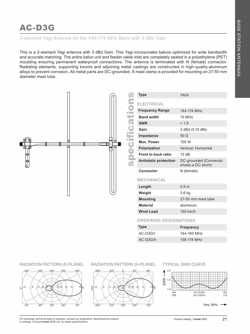
AC-D3G
This is a 2-element Yagi antenna with 3 dBd Gain. This Yagi incorporates baluns optimized for wide bandwidth and accurate matching. The entire balun unit and feeder cable inlet are completely sealed in a polyethylene (PET) moulding ensuring permanent waterproof connections. The antenna is terminated with N (female) connector. Radiating elements, supporting booms and adjoining metal castings are constructed in high-quality-aluminum alloys to prevent corrosion. All metal parts are DC-grounded. A mast clamp is provided for mounting on 27-50 mm diameter mast tube.
Type YAGI
ELECTRICALFrequency Range 144-174 MHz
Band width 15 MHz
SWR < 1.5
Gain 3 dBd (5.15 dBi)
Impedance 50 Ω
Max. Power 150 W
Polarization Vertical; Horizontal
Front to back ratio 12 dB
Antistatic protection DC-grounded (Connector shows a DC-short)
Connector N (female)
MECHANICALLength 0.9 m
Weight 3.6 kg
Mounting 27-50 mm mast tube
Material aluminum
Wind Load 150 km/h
ORDERING DESIGNATIONSType FrequencyAC-D3G/l 144-160 MHz
AC-D3G/h 158-174 MHz
2-element Yagi Antenna for the 144-174 MHz Band with 3 dBd Gain

TYPICAL SWR CURVE
SW
R
freq. MHz
1.0
2.0
1.5
RADIATION PATTERN (E-PLANE) RADIATION PATTERN (H-PLANE)+90°
-90°
+60°+30°
0°
+30°+60°
-60°-30° -30°-60°
0°
0°
180°
330°300°
90°
60°30°
210°240° 120°150°
270°
144158
AC-D6G/lAC-D6G/h
160174
+6 +3 0 -3 -6 -6 -3 0 +3 +6 +6 +3 0 -3 -6 -6 -3 0 +3 +6
For drawings, technical data or samples, contact our engeneers. Specifications subject to change. Consult Inmak 2000 Ltd. for latest specifications.
22 Product catalog | Inmak 2000
spec
ification
s
BA
SE
STA
TIO
N A
NT
EN
NA
S
AC-D6G
This is a 3-element Yagi antenna with 6 dBd Gain. This Yagi incorporates baluns optimized for wide bandwidth and accurate matching. The entire balun unit and feeder cable inlet are completely sealed in a polyethylene (PET) moulding ensuring permanent waterproof connections. The antenna is terminated with N (female) connector. Radiating elements, supporting booms and adjoining metal castings are constructed in high-quality-aluminum alloys to prevent corrosion. All metal parts are DC-grounded. A mast clamp is provided for mounting on 27-50 mm diameter mast tube.
Type YAGI
ELECTRICALFrequency Range 144-174 MHz
Band width 15 MHz
SWR < 1.5
Gain 6 dBd (8.15 dBd)
Impedance 50 Ω
Max. Power 150 W
Polarization Vertical; Horizontal
Front to back ratio 16 dB
Antistatic protection DC-grounded (Connector shows a DC-short)
Connector N (female)
MECHANICALLength 1.2 m
Weight 4.0 kg
Mounting 27-50 mm mast tube
Material aluminum
Wind Load 150 km/h
ORDERING DESIGNATIONSType FrequencyAC-D6G/l 144-160 MHz
AC-D6G/h 158-174 MHz
3-element Yagi Antenna for the 144-174 MHz Band with 6 dBd Gain

TYPICAL SWR CURVE
SW
R
freq. MHz
1.0
2.0
1.5
RADIATION PATTERN (E-PLANE) RADIATION PATTERN (H-PLANE)+90°
-90°
+60°+30°
0°
+30°+60°
-60°-30° -30°-60°
0°
0°
180°
330°300°
90°
60°30°
210°240° 120°150°
270°
144158
AC-D8G/lAC-D8G/h
160174
-0+8 +6 +3 -3 +6-3 0 +3 +8 0+8 +6 +3 -3 +6-3 0 +3 +8
Product catalog | Inmak 2000 23For drawings, technical data or samples, contact our engeneers. Specifications subject to change. Consult Inmak 2000 Ltd. for latest specifications.
spec
ification
s
BA
SE
STATIO
N A
NT
EN
NA
S
AC-D8G
This is a 5-element Yagi antenna with 8 dBd Gain. This Yagi incorporates baluns optimized for wide bandwidth and accurate matching. The entire balun unit and feeder cable inlet are completely sealed in a polyethylene (PET) moulding ensuring permanent waterproof connections. The antenna is terminated with N (female) connector. Radiating elements, supporting booms and adjoining metal castings are constructed in high-quality-aluminum alloys to prevent corrosion. All metal parts are DC-grounded. A mast clamp is provided for mounting on 27-50 mm diameter mast tube.
Type YAGI
ELECTRICALFrequency Range 144-174 MHz
Band width 15 MHz
SWR < 1.5
Gain 8 dBd (10.15 dBi)
Impedance 50 Ω
Max. Power 150 W
Polarization Vertical; Horizontal
Front to back ratio 16 dB
Antistatic protection DC-grounded (Connector shows a DC-short)
Connector N (female)
MECHANICALLength 1.95 m
Weight 4.6 kg
Mounting 27-50 mm mast tube
Material aluminum
Wind Load 150 km/h
ORDERING DESIGNATIONSType FrequencyAC-D8G/l 144-160 MHz
AC-D8G/h 158-174 MHz
5-element Yagi Antenna for the 144-174 MHz Band with 8 dBd Gain
TYPICAL SWR CURVE
SW
R
freq. MHz
1.0
2.0
1.5
MULTI-PURPOSE MOUNTING BRACKET RADIATION PATTERN (E-PLANE)0°
180°
330°300°
90°
60°30°
210°240° 120°150°
270° -90 -3 -6 -12 -3-12 -9 -6 0
144154164
BA2-1G/lBA2-1G/mBA2-1G/h
154164174
For drawings, technical data or samples, contact our engeneers. Specifications subject to change. Consult Inmak 2000 Ltd. for latest specifications.
24 Product catalog | Inmak 2000
spec
ification
s
BA
SE
STA
TIO
N A
NT
EN
NA
S
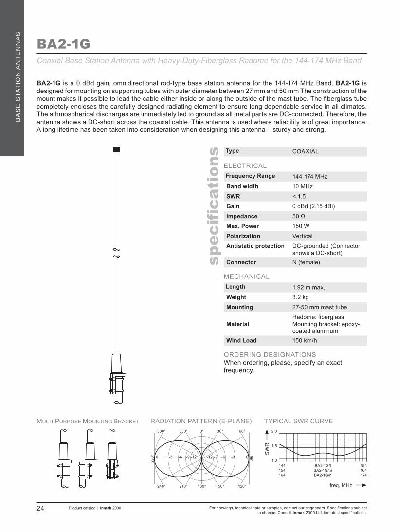
BA2-1G
BA2-1G is a 0 dBd gain, omnidirectional rod-type base station antenna for the 144-174 MHz Band. BA2-1G is designed for mounting on supporting tubes with outer diameter between 27 mm and 50 mm The construction of the mount makes it possible to lead the cable either inside or along the outside of the mast tube. The fiberglass tube completely encloses the carefully designed radiating element to ensure long dependable service in all climates. The athmospherical discharges are immediately led to ground as all metal parts are DC-connected. Therefore, the antenna shows a DC-short across the coaxial cable. This antenna is used where reliability is of great importance. A long lifetime has been taken into consideration when designing this antenna – sturdy and strong.
Type COAXIAL
ELECTRICALFrequency Range 144-174 MHz
Band width 10 MHz
SWR < 1.5
Gain 0 dBd (2.15 dBi)
Impedance 50 Ω
Max. Power 150 W
Polarization Vertical
Antistatic protection DC-grounded (Connector shows a DC-short)
Connector N (female)
MECHANICALLength 1.92 m max.
Weight 3.2 kg
Mounting 27-50 mm mast tube
MaterialRadome: fiberglassMounting bracket: epoxy-coated aluminum
Wind Load 150 km/h
ORDERING DESIGNATIONSWhen ordering, please, specify an exact frequency.
Coaxial Base Station Antenna with Heavy-Duty-Fiberglass Radome for the 144-174 MHz Band

TYPICAL SWR CURVE
SW
R
freq. MHz
1.0
2.0
1.5
MULTI-PURPOSE MOUNTING BRACKET RADIATION PATTERN (E-PLANE)0°
180°
330°300°
90°
60°30°
210°240° 120°150°
270° -6+3 0 -3 -9 0-9 -6 -3 +3
5 MHz Frequency Band
Product catalog | Inmak 2000 25For drawings, technical data or samples, contact our engeneers. Specifications subject to change. Consult Inmak 2000 Ltd. for latest specifications.
spec
ification
s
BA
SE
STATIO
N A
NT
EN
NA
S
BA2-3G
BA2-3G is a 3 dBd gain, omnidirectional rod-type base station antenna for the 144-174 MHz Band. BA2-3G is designed for mounting on supporting tubes with outer diameter between 27 mm and 50 mm The construction of the mount makes it possible to lead the cable either inside or along the outside of the mast tube. The fiberglass tube completely encloses the carefully designed radiating element to ensure long dependable service in all climates. The athmospherical discharges are immediately led to ground as all metal parts are DC-connected. Therefore, the antenna shows a DC-short across the coaxial cable. This antenna is used where reliability is of great importance. A long lifetime has been taken into consideration when designing this antenna – sturdy and strong.
Type OMNIDIRECTIONAL
ELECTRICALFrequency Range 144-174 MHz
Band width 5 MHz
SWR < 1.5
Gain 3 dBd (5.15 dBi)
Impedance 50 Ω
Max. Power 150 W
Polarization Vertical
Antistatic protection DC-grounded (Connector shows a DC-short)
Connector N (female)
MECHANICALLength 2.72 m max.
Weight 2.3 kg
Mounting 27-50 mm mast tube
MaterialRadome: fiberglassMounting bracket: epoxy-coated aluminum
Wind Load 150 km/h
ORDERING DESIGNATIONSWhen ordering, please, specify an exact frequency.
Omnidirectional Base Station Antenna with Heavy-Duty-Fiberglass Radomefor the 144-174 MHz Band

TYPICAL SWR CURVE
SW
R
freq. MHz
1.0
2.0
1.5
MULTI-PURPOSE MOUNTING BRACKET RADIATION PATTERN (E-PLANE)0°
180°
330°300°
90°
60°30°
210°240° 120°150°
270°
5 MHz Frequency Band
For drawings, technical data or samples, contact our engeneers. Specifications subject to change. Consult Inmak 2000 Ltd. for latest specifications.
26 Product catalog | Inmak 2000
spec
ification
s
BA
SE
STA
TIO
N A
NT
EN
NA
S
BA2-5GOmnidirectional Base Station Antenna with Heavy-Duty-Fiberglass Radomefor the 144-174 MHz BandBA2-5G is a 5 dBd gain, omnidirectional rod-type base station antenna for the 144-174 MHz Band. BA2-5G is designed for mounting on supporting tubes with outer diameter between 27 mm and 50 mm The construction of the mount makes it possible to lead the cable either inside or along the outside of the mast tube. The fiberglass tube completely encloses the carefully designed radiating element to ensure long dependable service in all climates. The athmospherical discharges are immediately led to ground as all metal parts are DC-connected. Therefore, the antenna shows a DC-short across the coaxial cable. This antenna is used where reliability is of great importance. A long lifetime has been taken into consideration when designing this antenna – sturdy and strong.
Type OMNIDIRECTIONAL
ELECTRICALFrequency Range 144-174 MHz
Band width 5 MHz
SWR < 1.5
Gain 5 dBd (7.15 dBi)
Impedance 50 Ω
Max. Power 150 W
Polarization Vertical
Antistatic protection DC-grounded (Connector shows a DC-short)
Connector N (female)
MECHANICALLength 4.5 m max.
Weight 4.2 kg
Mounting 27-50 mm mast tube
MaterialRadome: fiberglassMounting bracket: epoxy-coated aluminum
Wind Load 150 km/h
ORDERING DESIGNATIONSWhen ordering, please, specify an exact frequency.
-3+5 +3 0 -6 +3-6 -3 0 +5

TYPICAL SWR CURVE
SW
R
freq. MHz
1.0
2.0
1.5
MULTI-PURPOSE MOUNTING BRACKET RADIATION PATTERN (E-PLANE)0°
180°
330°300°
90°
60°30°
210°240° 120°150°
270° -90 -3 -6 -12 -3-12 -9 -6 0
144154164
ASKI 160/lASKI 160/mASKI 160/h
154164174
Product catalog | Inmak 2000 27For drawings, technical data or samples, contact our engeneers. Specifications subject to change. Consult Inmak 2000 Ltd. for latest specifications.
spec
ification
s
BA
SE
STATIO
N A
NT
EN
NA
S
ASKI 160
Type ASKI
ELECTRICALFrequency Range 144-174 MHz
Band width 20 MHz
SWR < 1.5
Gain 3 dBd (5.15 dBi)
Impedance 50 Ω
Max. Power 300 W
Polarization Vertical
Connector N (female)
MECHANICALLength 1.55 m max.
Weight 2.5 kg
Mounting 27-50 mm mast tube
MaterialRadome: aluminumMounting bracket:epoxy-coated aluminum
Wind Load 150 km/h
ORDERING DESIGNATIONSType FrequencyASKI 160/l 144-154 MHz
ASKI 160/m 154-164 MHz
ASKI 160/h 164-174 MHz
Base Station Antenna with Aluminum Radome for the 144-174 MHz Band
ASKI 160 is a 3 dBd gain, rod-type base station antenna for the 144-174 MHz Band. ASKI 160 is designed for mounting on supporting tubes with outer diameter between 27 mm and 50 mm The construction of the mount makes it possible to lead the cable either inside or along the outside of the mast tube. The aluminum tube completely encloses the carefully designed radiating element to ensure long dependable service in all climates. This antenna is used where reliability is of great importance. A long lifetime has been taken into consideration when designing this antenna – sturdy and strong.

TYPICAL SWR CURVE
SW
R
freq. MHz
1.0
2.0
1.5
RADIATION PATTERN (E-PLANE)0°
180°
330°300°
90°
60°30°
210°240° 120°150°
270°
144154164
B-2R/lB-2R/mB-2R/h
154164174
-6+3 0 -3 -9 0-9 -6 -3 +3
Radials as seen from either the top or the bottom
For drawings, technical data or samples, contact our engeneers. Specifications subject to change. Consult Inmak 2000 Ltd. for latest specifications.
28 Product catalog | Inmak 2000
spec
ification
s
BA
SE
STA
TIO
N A
NT
EN
NA
S
B-2R
Type BASE STATION
ELECTRICALFrequency Range 144-174 MHz
Band width 10 MHz
SWR < 1.5
Gain 3 dBd (5.15 dBi)
Impedance 50 Ω
Max. Power 500 W
Polarization Vertical
Antistatic protection N/A
Connector N (female)
MECHANICALLength 3.0 m max.
Weight 2.86 kg
Mounting 27-46 mm mast tube
Material aluminum
Wind Load 150 km/h
ORDERING DESIGNATIONSType FrequencyB-2R/l 144-154 MHz
B-2R/m 154-164 MHz
B-2R/h 164-174 MHz
Base Station Antenna for the 144-174 MHz Band with 3 dBd Gain
The B-2R antenna is a collinear 5/8-wave omnidirectional vertical antenna for the 144-174 MHz band. The B-2R features two sets of 1/4-wave radials which properly decouple the lower 5/8-wave radiator from the mast. The ruggedized B-2R is suitable for personal use. The antenna can terminate with an UHF or N connector. A mast clamp is provided for mounting on 27-43 mm diameter mast tube.

TYPICAL SWR CURVE
SW
R
freq. MHz
1.0
2.0
1.5
RADIATION PATTERN (E-PLANE) RADIATION PATTERN (H-PLANE)+90°
-90°
+60°+30°
0°
+30°+60°
-60°-30° -30°-60°
0°
0°
180°
330°300°
90°
60°30°
210°240° 120°150°
270°
144158
BD2-3G/lBD2-3G/h
160174
+3-6+3 0 -3 -9 0-9 -6 -3 +3 -6+3 0 -3 -9 0-9 -6 -3 +3
Product catalog | Inmak 2000 29For drawings, technical data or samples, contact our engeneers. Specifications subject to change. Consult Inmak 2000 Ltd. for latest specifications.
spec
ification
s
BA
SE
STATIO
N A
NT
EN
NA
S
BD2-3G
Type DIPOLE ARRAY
ELECTRICALFrequency Range 144-174 MHz
Band width 15 MHz
SWR < 1.5
Gain 3 dBd (5.15 dBi)
Impedance 50 Ω
Max Power 300 W
Polarization vertical
Antistatic protection DC-grounded (Connector shows a DC-short)
Connector N (female)
MECHANICALLength 3.5 m
Weight 10.5 kg
Mounting 27-50 mm mast tube
Material Aluminum
Wind Load 150 km/h
ORDERING DESIGNATIONSType FrequencyBD2-3G/l 144-160 MHz
BD2-3G/h 158-174 MHz
2-dipole Array for the 144-174 MHz Band
BD2-3G is a base station antenna compounded of 2 dipoles, which give the antenna 3-dBd gain. The antenna is supplied with two cables for each dipole and a SP2-2 cable splitter, which can terminate with any kind of connector. All metal parts are DC-grounded.

TYPICAL SWR CURVE
SW
R
freq. MHz
1.0
2.0
1.5
RADIATION PATTERN (E-PLANE) RADIATION PATTERN (H-PLANE)+90°
-90°
+60°+30°
0°
+30°+60°
-60°-30° -30°-60°
0°
0°
180°
330°300°
90°
60°30°
210°240° 120°150°
270°
144158
BD2-6G/lBD2-6G/h
160174
-3+6 +3 0 -6 +3-6 -3 0 +6 -3+6 +3 0 -6 +3-6 -3 0 +6
For drawings, technical data or samples, contact our engeneers. Specifications subject to change. Consult Inmak 2000 Ltd. for latest specifications.
30 Product catalog | Inmak 2000
spec
ification
s
BA
SE
STA
TIO
N A
NT
EN
NA
S
BD2-6G
Type DIPOLE ARRAY
ELECTRICALFrequency Range 144-174 MHz
Band width 15 MHz
SWR < 1.5
Gain 6 dBd (8.15 dBi)
Impedance 50 Ω
Max Power 300 W
Polarization vertical
Antistatic protection DC-grounded (Connector shows a DC-short)
Connector N (female)
MECHANICALLength 5.6 m
Weight 25 kg
Mounting 27-50 mm mast tube
Material aluminum
Wind Load 150 km/h
ORDERING DESIGNATIONSType FrequencyBD2-6G/l 144-160 MHz
BD2-6G/h 158-174 MHz
4-dipole Array for the 144-174 MHz Band
BD2-6G is a base station antenna compounded of 4 dipoles, which give the antenna 6-dBd gain. The antenna is supplied with four cables for each dipole and a SP2-4 cable splitter, which can terminate with any kind of connector. All metal parts are DC-grounded.

TYPICAL SWR CURVE
SW
R
freq. MHz
1.0
2.0
1.5
RADIATION PATTERN (E-PLANE) RADIATION PATTERN (H-PLANE)+90°
-90°
+60°+30°
0°
+30°+60°
-60°-30° -30°-60°
0°
0°
180°
330°300°
90°
60°30°
210°240° 120°150°
270°-6+3 0 -3 -9 0-9 -6 -3 +3 -6+3 0 -3 -9 0-9 -6 -3 +3
300320
AC3-D/lAC3-D/h
330350
Product catalog | Inmak 2000 31For drawings, technical data or samples, contact our engeneers. Specifications subject to change. Consult Inmak 2000 Ltd. for latest specifications.
spec
ification
s
BA
SE
STATIO
N A
NT
EN
NA
S
AC3-D
Type DIPOLE
ELECTRICALFrequency Range 300-350 MHz
Band width 30 MHz
SWR < 1.5
Gain 0 dBd (2.15 dBi)
Impedance 50 Ω
Max Power 150 W
Polarization Vertical; Horizontal
Antistatic protection DC-grounded (Connector shows a DC-short)
Connector N (female)
MECHANICALWeight 2.4 kg
Mounting 27-50 mm mast tube
Material aluminum
Wind Load 150 km/h
ORDERING DESIGNATIONSType FrequencyAC3-D/l 300-330 MHz
AC3-D/h 320-350 MHz
Center-Fed-Folded Dipole for the 300-350 MHz Band
Single, 0 dBd folded dipole incorporating a balun optimized for wide bandwidth and accurate matching. The entire balun unit and feeder terminations are completely sealed in a polyethylene (PET) moulding ensuring permanent waterproof connections. The dipole have been constructed with high-quality aluminum to prevent corrosion. All metal parts are DC-grounded. The antenna is supplied with clamp for mounting on 27-50 mm diameter mast tubes.

TYPICAL SWR CURVE
SW
R
freq. MHz
1.0
2.0
1.5
RADIATION PATTERN (E-PLANE) RADIATION PATTERN (H-PLANE)+90°
-90°
+60°+30°
0°
+30°+60°
-60°-30° -30°-60°
0°
0°
180°
330°300°
90°
60°30°
210°240° 120°150°
270°-6+3 0 -3 -9 0-9 -6 -3 +3 -6+3 0 -3 -9 0-9 -6 -3 +3
300312325337
AC3-D3G/lAC3-D3G/mlAC3-D3G/mhAC3-D3G/h
315327340350
For drawings, technical data or samples, contact our engeneers. Specifications subject to change. Consult Inmak 2000 Ltd. for latest specifications.
32 Product catalog | Inmak 2000
spec
ification
s
BA
SE
STA
TIO
N A
NT
EN
NA
S
AC3-D3G
This is a 2-element Yagi antenna with 3 dBd Gain. This Yagi incorporates baluns optimized for wide bandwidth and accurate matching. The entire balun unit and feeder cable inlet are completely sealed in a polyethylene (PET) moulding ensuring permanent waterproof connections. The antenna is terminated with N (female) connector. Radiating elements, supporting booms and adjoining metal castings are constructed in high-quality-aluminum alloys to prevent corrosion. All metal parts are DC-grounded. A mast clamp is provided for mounting on 27-50 mm diameter mast tube.
Type YAGI
ELECTRICALFrequency Range 300-350 MHz
Band width 15 MHz
SWR < 1.5
Gain 3 dBd (5.15 dBi)
Impedance 50 Ω
Max Power 150 W
Polarization Vertical; Horizontal
Front to back ratio 12 dB
Antistatic protection DC-grounded (Connector shows a DC-short)
Connector N (female)
MECHANICALLength 0.6 mWeight 3.0 kg
Mounting 27-50 mm mast tube
Material aluminum
Wind Load 150 km/h
ORDERING DESIGNATIONSType FrequencyAC3-D3G/l 300-315 MHz
AC3-D3G/ml 312-327 MHz
AC3-D3G/mh 325-340 MHz
AC3-D3G/h 337-350 MHz
2-element Yagi Antenna for the 300-350 MHz Band with 3 dBd Gain

TYPICAL SWR CURVE
SW
R
freq. MHz
1.0
2.0
1.5
RADIATION PATTERN (E-PLANE) RADIATION PATTERN (H-PLANE)+90°
-90°
+60°+30°
0°
+30°+60°
-60°-30° -30°-60°
0°
0°
180°
330°300°
90°
60°30°
210°240° 120°150°
270°
300312325337
AC3-D6G/lAC3-D6G/mlAC3-D6G/mhAC3-D6G/h
315327340350
+6 +3 0 -3 -6 -6 -3 0 +3 +6 +6 +3 0 -3 -6 -6 -3 0 +3 +6
Product catalog | Inmak 2000 33For drawings, technical data or samples, contact our engeneers. Specifications subject to change. Consult Inmak 2000 Ltd. for latest specifications.
spec
ification
s
BA
SE
STATIO
N A
NT
EN
NA
S
AC3-D6G
This is a 3-element Yagi antenna with 6 dBd Gain. This Yagi incorporates baluns optimized for wide bandwidth and accurate matching. The entire balun unit and feeder cable inlet are completely sealed in a polyethylene (PET) moulding ensuring permanent waterproof connections. The antenna is terminated with N (female) connector. Radiating elements, supporting booms and adjoining metal castings are constructed in high-quality-aluminum alloys to prevent corrosion. All metal parts are DC-grounded. A mast clamp is provided for mounting on 27-50 mm diameter mast tube.
Type YAGI
ELECTRICALFrequency Range 300-350 MHz
Band width 15 MHz
SWR < 1.5
Gain 6 dBd (8.15 dBi)
Impedance 50 Ω
Max Power 150 W
Polarization Vertical; Horizontal
Front to back ratio 16 dB
Antistatic protection DC-grounded (Connector shows a DC-short)
Connector N (female)
MECHANICALLength 0.85 mWeight 3.3 kg
Mounting 27-50 mm mast tube
Material aluminum
Wind Load 150 km/h
ORDERING DESIGNATIONSType FrequencyAC3-D6G/l 300-315 MHz
AC3-D6G/ml 312-327 MHz
AC3-D6G/mh 325-340 MHz
AC3-D6G/h 337-350 MHz
3-element Yagi Antenna for the 300-350 MHz Band with 6 dBd Gain

TYPICAL SWR CURVE
SW
R
freq. MHz
1.0
2.0
1.5
RADIATION PATTERN (E-PLANE) RADIATION PATTERN (H-PLANE)+90°
-90°
+60°+30°
0°
+30°+60°
-60°-30° -30°-60°
0°
0°
180°
330°300°
90°
60°30°
210°240° 120°150°
270°
300316331
AC3-D8G/lAC3-D8G/mAC3-D8G/h
319335350
-0+8 +6 +3 -3 +6-3 0 +3 +8 0+8 +6 +3 -3 +6-3 0 +3 +8
For drawings, technical data or samples, contact our engeneers. Specifications subject to change. Consult Inmak 2000 Ltd. for latest specifications.
34 Product catalog | Inmak 2000
spec
ification
s
BA
SE
STA
TIO
N A
NT
EN
NA
S
AC3-D8G
This is a 5-element Yagi antenna with 8 dBd Gain. This Yagi incorporates baluns optimized for wide bandwidth and accurate matching. The entire balun unit and feeder cable inlet are completely sealed in a polyethylene (PET) moulding ensuring permanent waterproof connections. The antenna is terminated with N (female) connector. Radiating elements, supporting booms and adjoining metal castings are constructed in high-quality-aluminum alloys to prevent corrosion. All metal parts are DC-grounded. A mast clamp is provided for mounting on 27-50 mm diameter mast tube.
Type YAGI
ELECTRICALFrequency Range 300-350 MHz
Band width 19 MHz
SWR < 1.5
Gain 8 dBd (10.15 dBi)
Impedance 50 Ω
Max Power 150 W
Polarization Vertical; Horizontal
Front to back ratio 18 dB
Antistatic protection DC-grounded (Connector shows a DC-short)
Connector N (female)
MECHANICALLength 1.3 mWeight 3.8 kg
Mounting 27-50 mm mast tube
Material aluminum
Wind Load 150 km/h
ORDERING DESIGNATIONSType FrequencyAC3-D8G/l 300-319 MHz
AC3-D8G/m 316-335 MHz
AC3-D8G/h 331-350 MHz
5-element Yagi Antenna for the 300-350 MHz Band with 8 dBd Gain

TYPICAL SWR CURVE
SW
R
freq. MHz
1.0
2.0
1.5
MULTI-PURPOSE MOUNTING BRACKET RADIATION PATTERN (E-PLANE)0°
180°
330°300°
90°
60°30°
210°240° 120°150°
270° -90 -3 -6 -12 -3-12 -9 -6 0
300320
BA3-1G/lBA3-1G/h
330350
Product catalog | Inmak 2000 35For drawings, technical data or samples, contact our engeneers. Specifications subject to change. Consult Inmak 2000 Ltd. for latest specifications.
spec
ification
s
BA
SE
STATIO
N A
NT
EN
NA
S
BA3-1G
BA3-1G is a 0 dBd gain, omnidirectional rod-type base station antenna for the 300-350 MHz Band. BA3-1G is designed for mounting on supporting tubes with outer diameter between 27 mm and 50 mm The construction of the mount makes it possible to lead the cable either inside or along the outside of the mast tube. The fiberglass tube completely encloses the carefully designed radiating element to ensure long dependable service in all climates. The athmospherical discharges are immediately led to ground as all metal parts are DC-connected. Therefore, the antenna shows a DC-short across the coaxial cable. This antenna is used where reliability is of great importance. A long lifetime has been taken into consideration when designing this antenna – sturdy and strong.
Type COAXIAL
ELECTRICALFrequency Range 300-350 MHz
Band width 30 MHz
SWR < 1.5
Gain 0 dBd (2.15 dBi)
Impedance 50 Ω
Max Power 150 W
Polarization vertical
Antistatic protection DC-grounded (Connector shows a DC-short)
Connector N (female)
MECHANICALLength 0.85 m
Weight 2.5 kg
Mounting 27-50 mm mast tube
MaterialRadome: fiberglassMounting bracket: epoxy-coated aluminum
Wind Load 150 km/h
ORDERING DESIGNATIONSType FrequencyBA3-1G/l 300-330 MHz
BA3-1G/h 320-350 MHz
Coaxial Base Station Antenna with Heavy-Duty-Fiberglass Radome for the 300-350 MHz Band

TYPICAL SWR CURVE
SW
R
freq. MHz
1.0
2.0
1.5
MULTI-PURPOSE MOUNTING BRACKET RADIATION PATTERN (E-PLANE)0°
180°
330°300°
90°
60°30°
210°240° 120°150°
270° -90 -3 -6 -12 -3-12 -9 -6 0
300320
ASKI 300/lASKI 300/h
330350
For drawings, technical data or samples, contact our engeneers. Specifications subject to change. Consult Inmak 2000 Ltd. for latest specifications.
36 Product catalog | Inmak 2000
spec
ification
s
BA
SE
STA
TIO
N A
NT
EN
NA
S
ASKI 300
Type ASKI
ELECTRICALFrequency Range 300-350 MHz
Band width 30 MHz
SWR < 1.5
Gain 3 dBd (5.15 dBi)
Impedance 50 Ω
Max Power 150 W
Polarization vertical
Connector N (female)
MECHANICALLength 0.70 m
Weight 1.8 kg
Mounting 27-50 mm mast tube
MaterialRadome: aluminumMounting bracket: epoxy-coated aluminum
Wind Load 150 km/h
ORDERING DESIGNATIONSType FrequencyASKI 300/l 300-330 MHz
ASKI 300/h 320-350 MHz
Base Station Antenna with Aluminum Radome for the 300-350 MHz Band
ASKI 300 is a 3 dBd gain, rod-type base station antenna for the 300-350 MHz Band. ASKI 300 is designed for mounting on supporting tubes with outer diameter between 27 mm and 50 mm The construction of the mount makes it possible to lead the cable either inside or along the outside of the mast tube. The aluminum tube completely encloses the carefully designed radiating element to ensure long dependable service in all climates. This antenna is used where reliability is of great importance. A long lifetime has been taken into consideration when designing this antenna – sturdy and strong.

TYPICAL SWR CURVE
SW
R
freq. MHz
1.0
2.0
1.5
RADIATION PATTERN (E-PLANE) RADIATION PATTERN (H-PLANE)+90°
-90°
+60°+30°
0°
+30°+60°
-60°-30° -30°-60°
0°
0°
180°
330°300°
90°
60°30°
210°240° 120°150°
270°-6+3 0 -3 -9 0-9 -6 -3 +3 -6+3 0 -3 -9 0-9 -6 -3 +3
300316332
BD3-3G/lBD3-3G/mBD3-3G/h
318334350
Product catalog | Inmak 2000 37For drawings, technical data or samples, contact our engeneers. Specifications subject to change. Consult Inmak 2000 Ltd. for latest specifications.
spec
ification
s
BA
SE
STATIO
N A
NT
EN
NA
S
BD3-3G
Type DIPOLE ARRAY
ELECTRICALFrequency Range 300-350 MHz
Band width 18 MHz
SWR < 1.5
Gain 3 dBd (5.15 dBi)
Impedance 50 Ω
Max Power 300 W
Polarization vertical
Antistatic protection DC-grounded (Connector shows a DC-short)
Connector N (female)
MECHANICALLength 0.95 m
Weight 4.0 kg
Mounting 27-50 mm mast tube
Material aluminum
Wind Load 150 km/h
ORDERING DESIGNATIONSType FrequencyBD3-3G/l 300-318 MHz
BD3-3G/m 316-334 MHz
BD3-3G/h 332-350 MHz
2-dipole Array for the 300-350 MHz Band
BD3-3G is a base station antenna compounded of 2 dipoles, which give the antenna 3-dBd gain. The antenna is supplied with two cables for each dipole and a SP3-2 cable splitter, which can terminate with any kind of connector. All metal parts are DC-grounded.
TYPICAL SWR CURVE
SW
R
freq. MHz
1.0
2.0
1.5
RADIATION PATTERN (E-PLANE) RADIATION PATTERN (H-PLANE)+90°
-90°
+60°+30°
0°
+30°+60°
-60°-30° -30°-60°
0°
0°
180°
330°300°
90°
60°30°
210°240° 120°150°
270°
300312325335
BD3-6G/lBD3-6G/mlBD3-6G/mhBD3-6G/h
315327340350
-3+6 +3 0 -6 +3-6 -3 0 +6 -3+6 +3 0 -6 +3-6 -3 0 +6
For drawings, technical data or samples, contact our engeneers. Specifications subject to change. Consult Inmak 2000 Ltd. for latest specifications.
38 Product catalog | Inmak 2000
spec
ification
s
BA
SE
STA
TIO
N A
NT
EN
NA
S
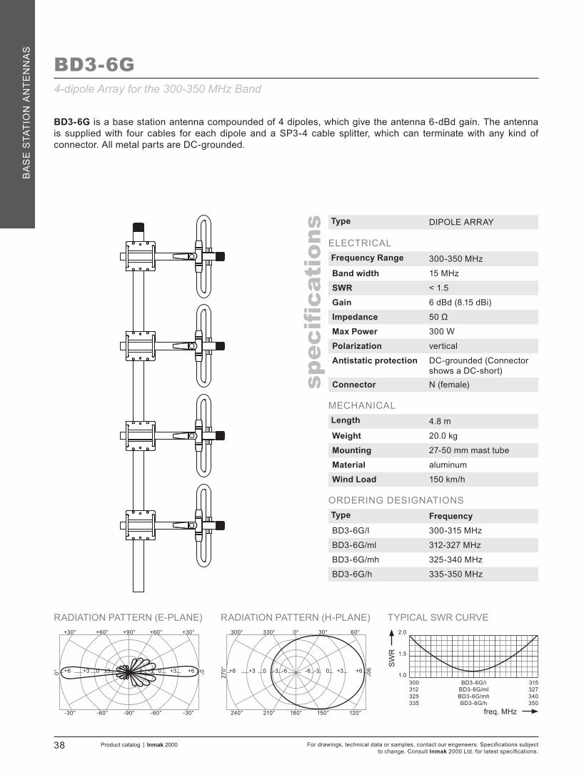
BD3-6G
Type DIPOLE ARRAY
ELECTRICALFrequency Range 300-350 MHz
Band width 15 MHz
SWR < 1.5
Gain 6 dBd (8.15 dBi)
Impedance 50 Ω
Max Power 300 W
Polarization vertical
Antistatic protection DC-grounded (Connector shows a DC-short)
Connector N (female)
MECHANICALLength 4.8 m
Weight 20.0 kg
Mounting 27-50 mm mast tube
Material aluminum
Wind Load 150 km/h
ORDERING DESIGNATIONSType FrequencyBD3-6G/l 300-315 MHz
BD3-6G/ml 312-327 MHz
BD3-6G/mh 325-340 MHz
BD3-6G/h 335-350 MHz
4-dipole Array for the 300-350 MHz Band
BD3-6G is a base station antenna compounded of 4 dipoles, which give the antenna 6-dBd gain. The antenna is supplied with four cables for each dipole and a SP3-4 cable splitter, which can terminate with any kind of connector. All metal parts are DC-grounded.

TYPICAL SWR CURVE
SW
R
freq. MHz
1.0
2.0
1.5
10 MHz Frequency Band
Product catalog | Inmak 2000 39For drawings, technical data or samples, contact our engeneers. Specifications subject to change. Consult Inmak 2000 Ltd. for latest specifications.
spec
ification
s
BA
SE
STATIO
N A
NT
EN
NA
S
AC70 is a ground-plane antenna of the triple-leg type. The antenna can be easily installed where no soldering is required. The antenna requires no adjustment. The antenna comprises an aluminum GP-head, one epoxy-coated steel radiator with open coil and three aluminum radials.
Type COAXIAL
ELECTRICALFrequency Range 400-470 MHz
Band width 10 MHz
SWR < 1.5
Gain 3 dBd (5.15 dBi)
Impedance 50 Ω
Max Power 150 W
Polarization vertical
Connector N (female)
MECHANICALLength 0.9 m max.
Weight 0.8 kg
Mounting 27-40 mm mast tube
Material Radiator: stainless steelRadials and GP head: aluminum
Wind Load 150 km/h
ORDERING DESIGNATIONSWhen ordering, please, specify an exact frequency.
AC703-radial Base Station Antenna for the 400-470 MHz Band
TYPICAL SWR CURVE
SW
R
freq. MHz
1.0
2.0
1.5
RADIATION PATTERN (E-PLANE) RADIATION PATTERN (H-PLANE)+90°
-90°
+60°+30°
0°
+30°+60°
-60°-30° -30°-60°
0°
0°
180°
330°300°
90°
60°30°
210°240° 120°150°
270°-6+3 0 -3 -9 0-9 -6 -3 +3 -6+3 0 -3 -9 0-9 -6 -3 +3
380405430
AC70-D/lAC70-D/mAC70-D/h
420445470
For drawings, technical data or samples, contact our engeneers. Specifications subject to change. Consult Inmak 2000 Ltd. for latest specifications.
40 Product catalog | Inmak 2000
spec
ification
s
BA
SE
STA
TIO
N A
NT
EN
NA
S
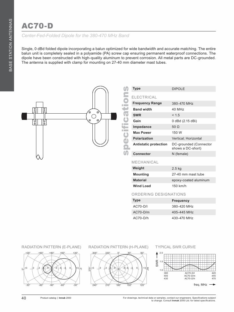
AC70-D
Single, 0 dBd folded dipole incorporating a balun optimized for wide bandwidth and accurate matching. The entire balun unit is completely sealed in a polyamide (PA) screw cap ensuring permanent waterproof connections. The dipole have been constructed with high-quality aluminum to prevent corrosion. All metal parts are DC-grounded. The antenna is supplied with clamp for mounting on 27-40 mm diameter mast tubes.
Type DIPOLE
ELECTRICALFrequency Range 380-470 MHz
Band width 40 MHz
SWR < 1.5
Gain 0 dBd (2.15 dBi)
Impedance 50 Ω
Max Power 150 W
Polarization Vertical; Horizontal
Antistatic protection DC-grounded (Connector shows a DC-short)
Connector N (female)
MECHANICALWeight 2.5 kg
Mounting 27-40 mm mast tube
Material epoxy-coated aluminum
Wind Load 150 km/h
ORDERING DESIGNATIONSType FrequencyAC70-D/l 380-420 MHz
AC70-D/m 405-445 MHz
AC70-D/h 430-470 MHz
Center-Fed-Folded Dipole for the 380-470 MHz Band

TYPICAL SWR CURVE
SW
R
freq. MHz
1.0
2.0
1.5
RADIATION PATTERN (E-PLANE) RADIATION PATTERN (H-PLANE)+90°
-90°
+60°+30°
0°
+30°+60°
-60°-30° -30°-60°
0°
0°
180°
330°300°
90°
60°30°
210°240° 120°150°
270°-6+3 0 -3 -9 0-9 -6 -3 +3 -6+3 0 -3 -9 0-9 -6 -3 +3
380405430
AC5-3G/lAC5-3G/mAC5-3G/h
420445470
Product catalog | Inmak 2000 41For drawings, technical data or samples, contact our engeneers. Specifications subject to change. Consult Inmak 2000 Ltd. for latest specifications.
spec
ification
s
BA
SE
STATIO
N A
NT
EN
NA
S
AC5-3G
This is a 2-element Yagi antenna with 3 dBd Gain. This Yagi incorporates baluns optimized for wide bandwidth and accurate matching. The entire balun unit is completely sealed in a polyamide (PA) screw cap ensuring permanent waterproof connections. The antenna is terminated with N (female) connector. Radiating elements, supporting booms and adjoining metal castings are constructed in high-quality-aluminum alloys to prevent corrosion. All metal parts are DC-grounded. A mast clamp is provided for mounting on 27-50 mm diameter mast tube.
Type YAGI
ELECTRICALFrequency Range 380-470 MHz
Band width 40 MHz
SWR < 1.5
Gain 3 dBd (5.15 dBi)
Impedance 50 Ω
Max Power 150 W
Polarization Vertical; Horizontal
Front to back ratio 12 dB
Antistatic protection DC-grounded (Connector shows a DC-short)
Connector N (female)
MECHANICALLength 0.5 mWeight 3.1 kg
Mounting 27-50 mm mast tube
Material epoxy-coated aluminum
Wind Load 150 km/h
ORDERING DESIGNATIONSType FrequencyAC5-3G/l 380-420 MHz
AC5-3G/m 405-445 MHz
AC5-3G/h 430-470 MHz
2-element Yagi Antenna for the 380-470 MHz Band with 3 dBd Gain
TYPICAL SWR CURVE
SW
R
freq. MHz
1.0
2.0
1.5
RADIATION PATTERN (E-PLANE) RADIATION PATTERN (H-PLANE)+90°
-90°
+60°+30°
0°
+30°+60°
-60°-30° -30°-60°
0°
0°
180°
330°300°
90°
60°30°
210°240° 120°150°
270°
380405430
AC5-5G/lAC5-5G/mAC5-5G/h
420445470
-3+6 +3 0 -6 +3-6 -3 0 +6 -3+6 +3 0 -6 +3-6 -3 0 +6
For drawings, technical data or samples, contact our engeneers. Specifications subject to change. Consult Inmak 2000 Ltd. for latest specifications.
42 Product catalog | Inmak 2000
spec
ification
s
BA
SE
STA
TIO
N A
NT
EN
NA
S
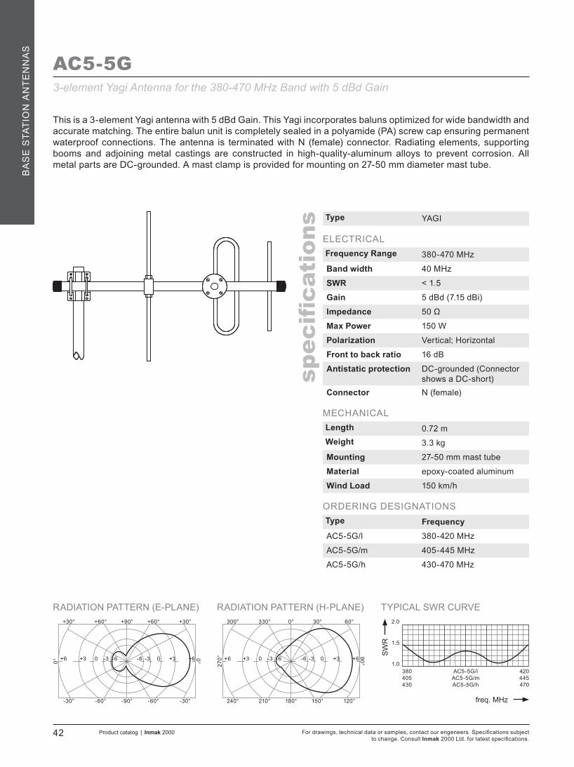
AC5-5G
This is a 3-element Yagi antenna with 5 dBd Gain. This Yagi incorporates baluns optimized for wide bandwidth and accurate matching. The entire balun unit is completely sealed in a polyamide (PA) screw cap ensuring permanent waterproof connections. The antenna is terminated with N (female) connector. Radiating elements, supporting booms and adjoining metal castings are constructed in high-quality-aluminum alloys to prevent corrosion. All metal parts are DC-grounded. A mast clamp is provided for mounting on 27-50 mm diameter mast tube.
Type YAGI
ELECTRICALFrequency Range 380-470 MHz
Band width 40 MHz
SWR < 1.5
Gain 5 dBd (7.15 dBi)
Impedance 50 Ω
Max Power 150 W
Polarization Vertical; Horizontal
Front to back ratio 16 dB
Antistatic protection DC-grounded (Connector shows a DC-short)
Connector N (female)
MECHANICALLength 0.72 mWeight 3.3 kg
Mounting 27-50 mm mast tube
Material epoxy-coated aluminum
Wind Load 150 km/h
ORDERING DESIGNATIONSType FrequencyAC5-5G/l 380-420 MHz
AC5-5G/m 405-445 MHz
AC5-5G/h 430-470 MHz
3-element Yagi Antenna for the 380-470 MHz Band with 5 dBd Gain

TYPICAL SWR CURVE
SW
R
freq. MHz
1.0
2.0
1.5
RADIATION PATTERN (E-PLANE) RADIATION PATTERN (H-PLANE)+90°
-90°
+60°+30°
0°
+30°+60°
-60°-30° -30°-60°
0°
0°
180°
330°300°
90°
60°30°
210°240° 120°150°
270°
380410435
AC5-7G/lAC5-7G/mAC5-7G/h
415445470
-0+7 +5 +3 -3 +5-3 0 +3 +7 0+7 +5 +3 -3 +5-3 0 +3 +7
Product catalog | Inmak 2000 43For drawings, technical data or samples, contact our engeneers. Specifications subject to change. Consult Inmak 2000 Ltd. for latest specifications.
spec
ification
s
BA
SE
STATIO
N A
NT
EN
NA
S
AC5-7G
This is a 5-element Yagi antenna with 7 dBd Gain. This Yagi incorporates baluns optimized for wide bandwidth and accurate matching. The entire balun unit is completely sealed in a polyamide (PA) screw cap ensuring permanent waterproof connections. The antenna is terminated with N (female) connector. Radiating elements, supporting booms and adjoining metal castings are constructed in high-quality-aluminum alloys to prevent corrosion. All metal parts are DC-grounded. A mast clamp is provided for mounting on 27-50 mm diameter mast tube.
Type YAGI
ELECTRICALFrequency Range 380-470 MHz
Band width 35 MHz
SWR < 1.5
Gain 7 dBd (9.15 dBi)
Impedance 50 Ω
Max Power 150 W
Polarization Vertical; Horizontal
Front to back ratio 16 dB
Antistatic protection DC-grounded (Connector shows a DC-short)
Connector N (female)
MECHANICALLength 1.02 mWeight 3.4 kg
Mounting 27-50 mm mast tube
Material epoxy-coated aluminum
Wind Load 150 km/h
ORDERING DESIGNATIONSType FrequencyAC5-7G/l 380-415 MHz
AC5-7G/m 410-445 MHz
AC5-7G/h 435-470 MHz
5-element Yagi Antenna for the 380-470 MHz Band with 7 dBd Gain

TYPICAL SWR CURVE
SW
R
freq. MHz
1.0
2.0
1.5
RADIATION PATTERN (E-PLANE) RADIATION PATTERN (H-PLANE)+90°
-90°
+60°+30°
0°
+30°+60°
-60°-30° -30°-60°
0°
0°
180°
330°300°
90°
60°30°
210°240° 120°150°
270°
380410435
AC5-10G/lAC5-10G/mAC5-10/h
415445470
+3+10 +7 +5 0 +70 +3 +5 +10 +3+10 +7 +5 0 +70 +3 +5 +10
For drawings, technical data or samples, contact our engeneers. Specifications subject to change. Consult Inmak 2000 Ltd. for latest specifications.
44 Product catalog | Inmak 2000
spec
ification
s
BA
SE
STA
TIO
N A
NT
EN
NA
S
AC5-10G
This is a 7-element Yagi antenna with 10 dBd Gain. This Yagi incorporates baluns optimized for wide bandwidth and accurate matching. The entire balun unit is completely sealed in a polyamide (PA) screw cap ensuring permanent waterproof connections. The antenna is terminated with N (female) connector. Radiating elements, supporting booms and adjoining metal castings are constructed in high-quality-aluminum alloys to prevent corrosion. All metal parts are DC-grounded. A mast clamp is provided for mounting on 27-50 mm diameter mast tube.
Type YAGI
ELECTRICALFrequency Range 380-470 MHz
Band width 35 MHz
SWR < 1.5
Gain 10 dBd (12.15 dBi)
Impedance 50 Ω
Max Power 150 W
Polarization Vertical; Horizontal
Front to back ratio 20 dB
Antistatic protection DC-grounded (Connector shows a DC-short)
Connector N (female)
MECHANICALLength 1.3 mWeight 3.6 kg
Mounting 27-50 mm mast tube
Material epoxy-coated aluminum
Wind Load 150 km/h
ORDERING DESIGNATIONSType FrequencyAC5-10G/l 380-415 MHz
AC5-10G/m 410-445 MHz
AC5-10/h 435-470 MHz
7-element Yagi Antenna for the 380-470 MHz Band with 10 dBd Gain

TYPICAL SWR CURVE
SW
R
freq. MHz
1.0
2.0
1.5
RADIATION PATTERN (E-PLANE) RADIATION PATTERN (H-PLANE)+90°
-90°
+60°+30°
0°
+30°+60°
-60°-30° -30°-60°
0°
0°
180°
330°300°
90°
60°30°
210°240° 120°150°
270°+3+12 +9 +6 0 +90 +3 +6 +12 +3+12 +9 +6 0 +90 +3 +6 +12
380410435
AC5-12G/lAC5-12G/mAC5-12/h
415445470
Product catalog | Inmak 2000 45For drawings, technical data or samples, contact our engeneers. Specifications subject to change. Consult Inmak 2000 Ltd. for latest specifications.
spec
ification
s
BA
SE
STATIO
N A
NT
EN
NA
S
AC5-12G
Type YAGI
ELECTRICALFrequency Range 380-470 MHz
Band width 35 MHz
SWR < 1.5
Gain 12 dBd (14.15 dBi)
Impedance 50 Ω
Max Power 150 W
Polarization Vertical; Horizontal
Front to back ratio 22 dB
Antistatic protection DC-grounded (Connector shows a DC-short)
Connector N (female)
MECHANICALLength 1.5 m
Weight 3.7 kg
Mounting 27-50 mm mast tube
Material epoxy-coated aluminum
Wind Load 150 km/h
ORDERING DESIGNATIONSType FrequencyAC5-12G/l 380-415 MHz
AC5-12G/m 410-445 MHz
AC5-12/h 435-470 MHz
9-element Yagi Antenna for the 380-470 MHz Band with 12 dBd Gain
This is a 9-element Yagi antenna with 12 dBd Gain. This Yagi incorporates baluns optimized for wide bandwidth and accurate matching. The entire balun unit is completely sealed in a polyamide (PA) screw cap ensuring permanent waterproof connections. The antenna is terminated with N (female) connector. Radiating elements, supporting booms and adjoining metal castings are constructed in high-quality-aluminum alloys to prevent corrosion. All metal parts are DC-grounded. A mast clamp is provided for mounting on 27-50 mm diameter mast tube.

TYPICAL SWR CURVE
SW
R
freq. MHz
1.0
2.0
1.5
MULTI-PURPOSE MOUNTING BRACKET RADIATION PATTERN (E-PLANE)0°
180°
330°300°
90°
60°30°
210°240° 120°150°
270° -90 -3 -6 -12 -3-12 -9 -6 0
380405430
BA70-1G/lBA70-1G/mBA70-1G/h
420445470
For drawings, technical data or samples, contact our engeneers. Specifications subject to change. Consult Inmak 2000 Ltd. for latest specifications.
46 Product catalog | Inmak 2000
spec
ification
s
BA
SE
STA
TIO
N A
NT
EN
NA
S
BA70-1G
BA70-1G is a 0 dBd gain, omnidirectional rod-type base station antenna for the 380-470 MHz Band. BA70-1G is designed for mounting on supporting tubes with outer diameter between 27 mm and 50 mm The construction of the mount makes it possible to lead the cable either inside or along the outside of the mast tube. The fiberglass tube completely encloses the carefully designed radiating element to ensure long dependable service in all climates. This antenna is used where reliability is of great importance. A long lifetime has been taken into consideration when designing this antenna – sturdy and strong.
Type COAXIAL
ELECTRICALFrequency Range 380-470 MHz
Band width 40 MHz
SWR < 1.2
Gain 0 dBd (2.15 dBi)
Impedance 50 Ω
Max Power 150 W
Polarization vertical
Antistatic protection N/A
Connector N (female)
MECHANICALLength 0.85 m
Weight 0.8 kg
Mounting 27-40 mm mast tube
MaterialRadome: fiberglassMounting bracket: epoxy-coated aluminum
Wind Load 150 km/h
ORDERING DESIGNATIONSType FrequencyBA70-1G/l 380-420 MHz
BA70-1G/m 405-445 MHz
BA70-1G/h 430-470 MHz
Coaxial Base Station Antenna with Heavy-Duty-Fiberglass Radome for the 380-470 MHz Band

TYPICAL SWR CURVE
SW
R
freq. MHz
1.0
2.0
1.5
MULTI-PURPOSE MOUNTING BRACKET RADIATION PATTERN (E-PLANE)0°
180°
330°300°
90°
60°30°
210°240° 120°150°
270°
10 MHz Frequency Band
-6+3 0 -3 -9 0-9 -6 -3 +3
Product catalog | Inmak 2000 47For drawings, technical data or samples, contact our engeneers. Specifications subject to change. Consult Inmak 2000 Ltd. for latest specifications.
spec
ification
s
BA
SE
STATIO
N A
NT
EN
NA
S
BA70-3G
BA70-3G is a 3 dBd gain, omnidirectional rod-type base station antenna for the 380-470 MHz Band. BA70-3G is designed for mounting on supporting tubes with outer diameter between 27 mm and 50 mm The construction of the mount makes it possible to lead the cable either inside or along the outside of the mast tube. The fiberglass tube completely encloses the carefully designed radiating element to ensure long dependable service in all climates. The athmospherical discharges are immediately led to ground as all metal parts are DC-connected. Therefore, the antenna shows a DC-short across the coaxial cable. This antenna is used where reliability is of great importance. A long lifetime has been taken into consideration when designing this antenna – sturdy and strong.
Type OMNIDIRECTIONAL
ELECTRICALFrequency Range 380-470 MHz
Band width 10 MHz
SWR < 1.5
Gain 3 dBd (5.15 dBi)
Impedance 50 Ω
Max Power 150 W
Polarization vertical
Antistatic protection DC-grounded (Connector shows a DC-short)
Connector N (female)
MECHANICALLength 2.8 m
Weight 1.6 kg
Mounting 27-40 mm mast tube
MaterialRadome: fiberglassMounting bracket: epoxy-coated aluminum
Wind Load 150 km/h
ORDERING DESIGNATIONSWhen ordering, please, specify an exact frequency.
Omnidirectional Base Station Antenna with Heavy-Duty-Fiberglass Radomefor the 380-470 MHz Band

TYPICAL SWR CURVE
SW
R
freq. MHz
1.0
2.0
1.5
MULTI-PURPOSE MOUNTING BRACKET RADIATION PATTERN (E-PLANE)0°
180°
330°300°
90°
60°30°
210°240° 120°150°
270°
10 MHz Frequency Band
For drawings, technical data or samples, contact our engeneers. Specifications subject to change. Consult Inmak 2000 Ltd. for latest specifications.
48 Product catalog | Inmak 2000
spec
ification
s
BA
SE
STA
TIO
N A
NT
EN
NA
S
Omnidirectional Base Station Antenna with Heavy-Duty-Fiberglass Radomefor the 380-470 MHz Band
-3+5 +3 0 -6 +3-6 -3 0 +5
BA70-5G
BA70-5G is a 5 dBd gain, omnidirectional rod-type base station antenna for the 380-470 MHz Band. BA70-5G is designed for mounting on supporting tubes with outer diameter between 27 mm and 50 mm The construction of the mount makes it possible to lead the cable either inside or along the outside of the mast tube. The fiberglass tube completely encloses the carefully designed radiating element to ensure long dependable service in all climates. The athmospherical discharges are immediately led to ground as all metal parts are DC-connected. Therefore, the antenna shows a DC-short across the coaxial cable. This antenna is used where reliability is of great importance. A long lifetime has been taken into consideration when designing this antenna – sturdy and strong.
Type OMNIDIRECTIONAL
ELECTRICALFrequency Range 380-470 MHz
Band width 10 MHz
SWR < 1.5
Gain 5 dBd (7.15 dBi)
Impedance 50 Ω
Max Power 150 W
Polarization vertical
Antistatic protection DC-grounded (Connector shows a DC-short)
Connector N (female)
MECHANICALLength 3.1 m
Weight 3.0 kg
Mounting 27-40 mm mast tube
MaterialRadome: fiberglassMounting bracket: epoxy-coated aluminum
Wind Load 150 km/h
ORDERING DESIGNATIONSWhen ordering, please, specify an exact frequency.
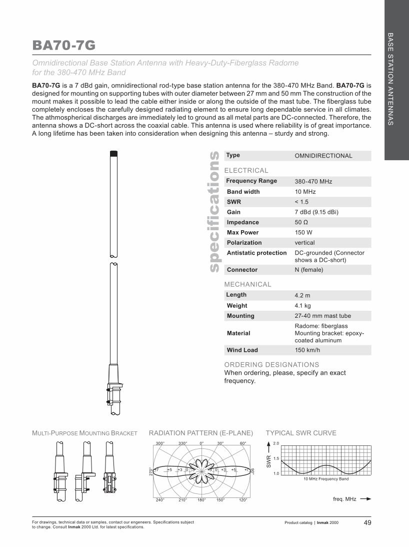
TYPICAL SWR CURVE
SW
R
freq. MHz
1.0
2.0
1.5
MULTI-PURPOSE MOUNTING BRACKET RADIATION PATTERN (E-PLANE)0°
180°
330°300°
90°
60°30°
210°240° 120°150°
270°
10 MHz Frequency Band
Product catalog | Inmak 2000 49For drawings, technical data or samples, contact our engeneers. Specifications subject to change. Consult Inmak 2000 Ltd. for latest specifications.
spec
ification
s
BA
SE
STATIO
N A
NT
EN
NA
S
BA70-7GOmnidirectional Base Station Antenna with Heavy-Duty-Fiberglass Radomefor the 380-470 MHz BandBA70-7G is a 7 dBd gain, omnidirectional rod-type base station antenna for the 380-470 MHz Band. BA70-7G is designed for mounting on supporting tubes with outer diameter between 27 mm and 50 mm The construction of the mount makes it possible to lead the cable either inside or along the outside of the mast tube. The fiberglass tube completely encloses the carefully designed radiating element to ensure long dependable service in all climates. The athmospherical discharges are immediately led to ground as all metal parts are DC-connected. Therefore, the antenna shows a DC-short across the coaxial cable. This antenna is used where reliability is of great importance. A long lifetime has been taken into consideration when designing this antenna – sturdy and strong.
Type OMNIDIRECTIONAL
ELECTRICALFrequency Range 380-470 MHz
Band width 10 MHz
SWR < 1.5
Gain 7 dBd (9.15 dBi)
Impedance 50 Ω
Max Power 150 W
Polarization vertical
Antistatic protection DC-grounded (Connector shows a DC-short)
Connector N (female)
MECHANICALLength 4.2 m
Weight 4.1 kg
Mounting 27-40 mm mast tube
MaterialRadome: fiberglassMounting bracket: epoxy-coated aluminum
Wind Load 150 km/h
ORDERING DESIGNATIONSWhen ordering, please, specify an exact frequency.
0+7 +5 +3 -3 +5 -3 0 +3 +7

TYPICAL SWR CURVE
SW
R
freq. MHz
1.0
2.0
1.5
MULTI-PURPOSE MOUNTING BRACKET RADIATION PATTERN (E-PLANE)0°
180°
330°300°
90°
60°30°
210°240° 120°150°
270° -90 -3 -6 -12 -3-12 -9 -6 0
380405430
ASKI 450/lASKI 450/mASKI 450/h
420445470
For drawings, technical data or samples, contact our engeneers. Specifications subject to change. Consult Inmak 2000 Ltd. for latest specifications.
50 Product catalog | Inmak 2000
spec
ification
s
BA
SE
STA
TIO
N A
NT
EN
NA
S
ASKI 450
ASKI 450 is a 3 dBd gain, rod-type base station antenna for the 380-470 MHz Band. ASKI 450 is designed for mounting on supporting tubes with outer diameter between 27 mm and 50 mm The construction of the mount makes it possible to lead the cable either inside or along the outside of the mast tube. The aluminum tube completely encloses the carefully designed radiating element to ensure long dependable service in all climates. This antenna is used where reliability is of great importance. A long lifetime has been taken into consideration when designing this antenna – sturdy and strong.
Type ASKI
ELECTRICALFrequency Range 380-470 MHz
Band width 40 MHz
SWR < 1.5
Gain 3 dBd (5.15 dBi)
Impedance 50 Ω
Max Power 150 W
Polarization vertical
Connector N (female)
MECHANICALLength 0.65 m
Weight 1.7 kg
Mounting 27-50 mm mast tube
MaterialRadome: aluminumMounting bracket:epoxy-coated aluminum
Wind Load 150 km/h
ORDERING DESIGNATIONSType FrequencyASKI 450/l 380-420 MHz
ASKI 450/m 405-445 MHz
ASKI 450/h 430-470 MHz
Base Station Antenna with Aluminum Radome for the 380-470 MHz Band
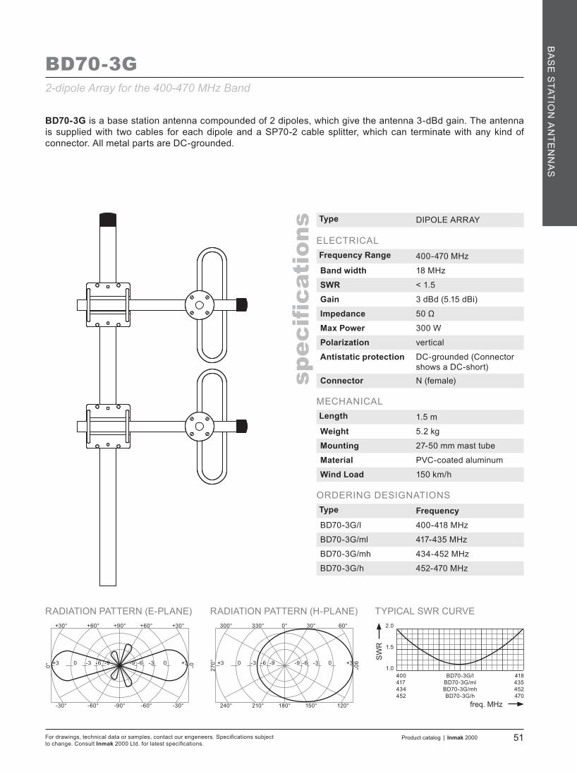
TYPICAL SWR CURVE
SW
R
freq. MHz
1.0
2.0
1.5
RADIATION PATTERN (E-PLANE) RADIATION PATTERN (H-PLANE)+90°
-90°
+60°+30°
0°
+30°+60°
-60°-30° -30°-60°
0°
0°
180°
330°300°
90°
60°30°
210°240° 120°150°
270°-6+3 0 -3 -9 0-9 -6 -3 +3 -6+3 0 -3 -9 0-9 -6 -3 +3
400417434452
BD70-3G/lBD70-3G/mlBD70-3G/mhBD70-3G/h
418435452470
Product catalog | Inmak 2000 51For drawings, technical data or samples, contact our engeneers. Specifications subject to change. Consult Inmak 2000 Ltd. for latest specifications.
spec
ification
s
BA
SE
STATIO
N A
NT
EN
NA
S
BD70-3G
Type DIPOLE ARRAY
ELECTRICALFrequency Range 400-470 MHz
Band width 18 MHz
SWR < 1.5
Gain 3 dBd (5.15 dBi)
Impedance 50 Ω
Max Power 300 W
Polarization vertical
Antistatic protection DC-grounded (Connector shows a DC-short)
Connector N (female)
MECHANICALLength 1.5 m
Weight 5.2 kg
Mounting 27-50 mm mast tube
Material PVC-coated aluminum
Wind Load 150 km/h
ORDERING DESIGNATIONSType FrequencyBD70-3G/l 400-418 MHz
BD70-3G/ml 417-435 MHz
BD70-3G/mh 434-452 MHz
BD70-3G/h 452-470 MHz
2-dipole Array for the 400-470 MHz Band
BD70-3G is a base station antenna compounded of 2 dipoles, which give the antenna 3-dBd gain. The antenna is supplied with two cables for each dipole and a SP70-2 cable splitter, which can terminate with any kind of connector. All metal parts are DC-grounded.

TYPICAL SWR CURVE
SW
R
freq. MHz
1.0
2.0
1.5
RADIATION PATTERN (E-PLANE) RADIATION PATTERN (H-PLANE)+90°
-90°
+60°+30°
0°
+30°+60°
-60°-30° -30°-60°
0°
0°
180°
330°300°
90°
60°30°
210°240° 120°150°
270°
400417434452
BD70-6G/lBD70-6G/mlBD70-6G/mhBD70-6G/h
418435452470
-3+6 +3 0 -6 +3-6 -3 0 +6 -3+6 +3 0 -6 +3-6 -3 0 +6
For drawings, technical data or samples, contact our engeneers. Specifications subject to change. Consult Inmak 2000 Ltd. for latest specifications.
52 Product catalog | Inmak 2000
spec
ification
s
BA
SE
STA
TIO
N A
NT
EN
NA
S
BD70-6G
Type DIPOLE ARRAY
ELECTRICALFrequency Range 400-470 MHz
Band width 18 MHz
SWR < 1.5
Gain 6 dBd (8.15 dBi)
Impedance 50 Ω
Max Power 300 W
Polarization vertical
Antistatic protection DC-grounded (Connector shows a DC-short)
Connector N (female)
MECHANICALLength 3.0 m
Weight 10.0 kg
Mounting 27-50 mm mast tube
Material PVC-coated aluminum
Wind Load 150 km/h
ORDERING DESIGNATIONSType FrequencyBD70-6G/l 400-418 MHz
BD70-6G/ml 417-435 MHz
BD70-6G/mh 434-452 MHz
BD70-6G/h 452-470 MHz
4-dipole Array for the 400-470 MHz Band
BD70-6G is a base station antenna compounded of 4 dipoles, which give the antenna 6-dBd gain. The antenna is supplied with four cables for each dipole and a SP70-4 cable splitter, which can terminate with any kind of connector. All metal parts are DC-grounded.

TYPICAL SWR CURVE
SW
R
freq. MHz
1.0
2.0
1.5
RADIATION PATTERN (E-PLANE) RADIATION PATTERN (H-PLANE)+90°
-90°
+60°+30°
0°
+30°+60°
-60°-30° -30°-60°
0°
0°
180°
330°300°
90°
60°30°
210°240° 120°150°
270°
820890
AC6-10G/lAC6-10G/h
890960
0+10 +7 +3 -3 +7-3 0 +3 +10 0+10 +7 +3 -3 +7-3 0 +3 +10
Product catalog | Inmak 2000 53For drawings, technical data or samples, contact our engeneers. Specifications subject to change. Consult Inmak 2000 Ltd. for latest specifications.
spec
ification
s
BA
SE
STATIO
N A
NT
EN
NA
S
AC6-10G
This is a 7-element Yagi antenna with 10 dBd Gain. This Yagi incorporates baluns optimized for wide bandwidth and accurate matching. The antenna is terminated with N (female) connector. Radiating elements, supporting booms and adjoining metal castings are constructed in high-quality-aluminum alloys to prevent corrosion. All metal parts are DC-grounded. A mast clamp is provided for mounting on 27-50 mm diameter mast tube.
Type YAGI
ELECTRICALFrequency Range 820-960 MHz
Band width 70 MHz
SWR < 1.5
Gain 10 dBd (12.15 dBi)
Impedance 50 Ω
Max Power 150 W
Polarization Vertical; Horizontal
Front to back ratio 20 dB
Antistatic protection N/A
Connector N (female)
MECHANICALLength 0.75 m
Weight 1.5 kg
Mounting 27-40 mm mast tube
Material PVC-coated aluminum
Wind Load 150 km/h
ORDERING DESIGNATIONSType FrequencyAC6-10G/l 820-890 MHz
AC6-10G/h 890-960 MHz
7-element Yagi Antenna for the 820-960 MHz Band with 10 dBd Gain

TYPICAL SWR CURVE
SW
R
freq. MHz
1.0
2.0
1.5
RADIATION PATTERN (E-PLANE) RADIATION PATTERN (H-PLANE)+90°
-90°
+60°+30°
0°
+30°+60°
-60°-30° -30°-60°
0°
0°
180°
330°300°
90°
60°30°
210°240° 120°150°
270°+3+12 +9 +6 0 +90 +3 +6 +12 +3+12 +9 +6 0 +90 +3 +6 +12
For drawings, technical data or samples, contact our engeneers. Specifications subject to change. Consult Inmak 2000 Ltd. for latest specifications.
54 Product catalog | Inmak 2000
spec
ification
s
BA
SE
STA
TIO
N A
NT
EN
NA
S
AC6-12G
This is a 10-element Yagi antenna with 12 dBd Gain. This Yagi incorporates baluns optimized for wide bandwidth and accurate matching. The antenna is terminated with N (female) connector. Radiating elements, supporting booms and adjoining metal castings are constructed in high-quality-aluminum alloys to prevent corrosion. All metal parts are DC-grounded. A mast clamp is provided for mounting on 27-50 mm diameter mast tube.
Type YAGI
ELECTRICALFrequency Range 820-960 MHz
Band width 70 MHz
SWR < 1.5
Gain 12 dBd (14.15 dBi)
Impedance 50 Ω
Max Power 150 W
Polarization Vertical; Horizontal
Front to back ratio 22 dB
Antistatic protection N/A
Connector N (female)
MECHANICALLength 1.13 m
Weight 1.6 kg
Mounting 27-40 mm mast tube
Material PVC-coated aluminum
Wind Load 150 km/h
ORDERING DESIGNATIONSType FrequencyAC6-12G/l 820-890 MHz
AC6-12G/h 890-960 MHz
10-element Yagi Antenna for the 820-960 MHz Band with 12 dBd Gain

TYPICAL SWR CURVE
SW
R
freq. MHz
1.0
2.0
1.5
MULTI-PURPOSE MOUNTING BRACKET RADIATION PATTERN (E-PLANE)0°
180°
330°300°
90°
60°30°
210°240° 120°150°
270° -90 -3 -6 -12 -3-12 -9 -6 0
820860910
BA90-1G/lBA90-1G/mBA90-1G/h
870910960
Product catalog | Inmak 2000 55For drawings, technical data or samples, contact our engeneers. Specifications subject to change. Consult Inmak 2000 Ltd. for latest specifications.
spec
ification
s
BA
SE
STATIO
N A
NT
EN
NA
S
BA90-1G
BA90-1G is a 0 dBd gain, omnidirectional rod-type base station antenna for the 820-960 MHz Band. BA90-1G is designed for mounting on supporting tubes with outer diameter between 27 mm and 40 mm The construction of the mount makes it possible to lead the cable either inside or along the outside of the mast tube. The fiberglass tube completely encloses the carefully designed radiating element to ensure long dependable service in all climates. This antenna is used where reliability is of great importance. A long lifetime has been taken into consideration when designing this antenna – sturdy and strong.
Type COAXIAL
ELECTRICALFrequency Range 820-960 MHz
Band width 50 MHz
SWR < 1.5
Gain 0 dBd (2.15 dBi)
Impedance 50 Ω
Max Power 150 W
Polarization vertical
Antistatic protection N/A
Connector N (female)
MECHANICALLength 0.7 m
Weight 1.0 kg
Mounting 27-40 mm mast tube
MaterialRadome: fiberglassMounting bracket: epoxy-coated aluminum
Wind Load 150 km/h
ORDERING DESIGNATIONSType FrequencyBA90-1G/l 820-870 MHzBA90-1G/m 860-910 MHzBA90-1G/h 910-960 MHz
Coaxial Base Station Antenna with Heavy-Duty-Fiberglass Radome for the 820-960 MHz Band

TYPICAL SWR CURVE
SW
R
freq. MHz
1.0
2.0
1.5
MULTI-PURPOSE MOUNTING BRACKET RADIATION PATTERN (E-PLANE)0°
180°
330°300°
90°
60°30°
210°240° 120°150°
270°
820860910
BA90-3G/lBA90-3G/mBA90-3G/h
870910960
-6+3 0 -3 -9 0-9 -6 -3 +3
For drawings, technical data or samples, contact our engeneers. Specifications subject to change. Consult Inmak 2000 Ltd. for latest specifications.
56 Product catalog | Inmak 2000
spec
ification
s
BA
SE
STA
TIO
N A
NT
EN
NA
S
BA90-3G
BA90-3G is a 3 dBd gain, omnidirectional rod-type base station antenna for the 820-960 MHz Band. BA90-3G is designed for mounting on supporting tubes with outer diameter between 27 mm and 40 mm The construction of the mount makes it possible to lead the cable either inside or along the outside of the mast tube. The fiberglass tube completely encloses the carefully designed radiating element to ensure long dependable service in all climates. This antenna is used where reliability is of great importance. A long lifetime has been taken into consideration when designing this antenna – sturdy and strong.
Type OMNIDIRECTIONAL
ELECTRICALFrequency Range 820-960 MHz
Band width 50 MHz
SWR < 1.5
Gain 3 dBd (5.15 dBi)
Impedance 50 Ω
Max Power 100 W
Polarization vertical
Antistatic protection N/A
Connector N (female)
MECHANICALLength 0.7 m
Weight 1.4 kg
Mounting 27-40 mm mast tube
MaterialRadome: fiberglassMounting bracket: epoxy-coated aluminum
Wind Load 150 km/h
ORDERING DESIGNATIONSType FrequencyBA90-3G/l 820-870 MHz
BA90-3G/m 860-910 MHz
BA90-3G/h 910-960 MHz
Omnidirectional Base Station Antenna with Heavy-Duty-Fiberglass Radomefor the 820-960 MHz Band

TYPICAL SWR CURVE
SW
R
freq. MHz
1.0
2.0
1.5
RADIATION PATTERN (E-PLANE) RADIATION PATTERN (H-PLANE)+90°
-90°
+60°+30°
0°
+30°+60°
-60°-30° -30°-60°
0°
0°
180°
330°300°
90°
60°30°
210°240° 120°150°
270°
1100 AC1.2-7G 1300
-0+7 +5 +3 -3 +5-3 0 +3 +7 0+7 +5 +3 -3 +5-3 0 +3 +7
Product catalog | Inmak 2000 57For drawings, technical data or samples, contact our engeneers. Specifications subject to change. Consult Inmak 2000 Ltd. for latest specifications.
spec
ification
s
BA
SE
STATIO
N A
NT
EN
NA
S
AC1.2-7G
This is a 4-element Yagi antenna with 7 dBd Gain. This Yagi incorporates baluns optimized for wide bandwidth and accurate matching. The antenna is terminated with N (female) connector. Radiating elements, supporting booms and adjoining metal castings are constructed in high-quality-aluminum alloys to prevent corrosion. A mast clamp is provided for mounting on 27-50 mm diameter mast tube.
Type YAGI
ELECTRICALFrequency Range 1100-1300 MHz
Band width 30 MHz
SWR < 1.5
Gain 7 dBd (9.15 dBi)
Impedance 50 Ω
Max Power 150 W
Polarization Vertical; Horizontal
Front to back ratio 20 dB
Antistatic protection N/A
Connector N (female)
MECHANICALLength 0.385 m
Weight 1.0 kg
Mounting 27-40 mm mast tube
Material PVC-coated aluminum
Wind Load 150 km/h
ORDERING DESIGNATIONSType FrequencyAC1.2-7G 1100-1300 MHz
4-element Yagi Antenna for the 1100-1300 MHz Band with 7 dBd Gain

TYPICAL SWR CURVE
SW
R
freq. MHz
1.0
2.0
1.5
RADIATION PATTERN (E-PLANE) RADIATION PATTERN (H-PLANE)+90°
-90°
+60°+30°
0°
+30°+60°
-60°-30° -30°-60°
0°
0°
180°
330°300°
90°
60°30°
210°240° 120°150°
270°
1100 AC1.2-11G 1300
+3+11 +9 +6 0 +90 +3 +6 +11 +3+11 +9 +6 0 +90 +3 +6 +11
AC1.2-11G
This is a 9-element Yagi antenna with 11 dBd Gain. This Yagi incorporates baluns optimized for wide bandwidth and accurate matching. The antenna is terminated with N (female) connector. Radiating elements, supporting booms and adjoining metal castings are constructed in high-quality-aluminum alloys to prevent corrosion. A mast clamp is provided for mounting on 27-50 mm diameter mast tube.
Type YAGI
ELECTRICALFrequency Range 1100-1300 MHz
Band width 100 MHz
SWR < 1.5
Gain 11 dBd (13.15 dBi)
Impedance 50 Ω
Max Power 150 W
Polarization Vertical; Horizontal
Front to back ratio 20 dB
Antistatic protection N/A
Connector N (female)
MECHANICALLength 0.8 m
Weight 1.1 kg
Mounting 27-40 mm mast tube
Material PVC-coated aluminum
Wind Load 150 km/h
ORDERING DESIGNATIONSType FrequencyAC1.2-11G 1100-1300 MHz
9-element Yagi Antenna for the 1100-1300 MHz Band with 11 dBd Gain
For drawings, technical data or samples, contact our engeneers. Specifications subject to change. Consult Inmak 2000 Ltd. for latest specifications.
58 Product catalog | Inmak 2000
spec
ification
s
BA
SE
STA
TIO
N A
NT
EN
NA
S

TYPICAL SWR CURVE
SW
R
freq. MHz
1.0
2.0
1.5
RADIATION PATTERN (H-PLANE)0°
180°
330°300°
90°
60°30°
210°240° 120°150°
270°
25 MHz Frequency Band
0+6 +5 +3 -3 +5 -3 0 +3 +6
BA1.2-6G
BA1.2-6G is a 6 dBi gain, omnidirectional rod-type base station antenna for the 1.2 GHz Band. BA1.2-6G is designed for mounting on supporting tubes with outer diameter between 25 mm and 48 mm. The fiberglass tube completely encloses the carefully designed radiating element to ensure excellent performance in all climate conditions. This antenna is used where reliability is of great importance. A long lifetime has been taken into consideration when designing this antenna – sturdy and strong.
Type OMNIDIRECTIONAL
ELECTRICALFrequency Range 1100-1300 MHz
Band width 25 MHz
SWR < 1.5
Gain 6 dBd (8.15 dBi)
Impedance 50 Ω
Max Power 100 W
Polarization vertical
Antistatic protection N/A
Connector N (female)
MECHANICALLength 1.0 m
Weight 0.7 kg
Mounting 25-48 mm mast tube
MaterialRadome: fiberglassMounting bracket: stainless steel
Wind Load 150 km/h
ORDERING DESIGNATIONSType FrequencyBA1.2-6G 1100-1300 MHz
Omnidirectional Base Station Antenna with Heavy-Duty-Fiberglass Radomefor the 1.2 GHz Band
Product catalog | Inmak 2000 59For drawings, technical data or samples, contact our engeneers. Specifications subject to change. Consult Inmak 2000 Ltd. for latest specifications.
spec
ification
s
BA
SE
STATIO
N A
NT
EN
NA
S

TYPICAL SWR CURVE
SW
R
freq. MHz
1.0
2.0
1.5
RADIATION PATTERN (E-PLANE) RADIATION PATTERN (H-PLANE)+90°
-90°
+60°+30°
0°
+30°+60°
-60°-30° -30°-60°
0°
0°
180°
330°300°
90°
60°30°
210°240° 120°150°
270°
For drawings, technical data or samples, contact our engeneers. Specifications subject to change. Consult Inmak 2000 Ltd. for latest specifications.
60 Product catalog | Inmak 2000
spec
ification
s
BA
SE
STA
TIO
N A
NT
EN
NA
S
60 MHz Frequency Band
+6+24 +18 +12 0 +180 +6 +12 +24 +6+24 +18 +12 0 +180 +6 +12 +24
ACP1.2-24G
ACP1.2-24G is a 24 dBi gain, wire grid parabolic base station antenna for the 1.2 GHz Band. Due to its grid parabolic reflector the ACP1.2-24G attains wide band width and strong gain. Constructed of welded steel wires which are galvanized and then powder coat painted, they offer extremely long service life in the most extreme environmental conditions. The wire grid semi-parabolic design offers unsurpassed low wind loading while maintaining good RF performance. The antenna is designed for mounting on supporting tubes with outer diameter between 30 mm and 50 mm. It can be mounted for both vertical and horizontal polarization. The antenna terminates with an N female connector.
Type Wire Grid Parabolic
ELECTRICALFrequency Range 1100-1300 MHz
Band width 60 MHz
SWR < 1.5
Gain 24 dBi
Impedance 50 Ω
Max Power 100 W
Polarization Vertical; Horizontal
Front to back ratio 31 dB
Antistatic protection DC-grounded (Connector shows a DC-short)
Connector N (female)
MECHANICALDimensions 900 x 600 mm
Weight 5.4 kg
Mounting 30-50 mm mast tube
Material Powder-coated steel
Wind Load 150 km/h
ORDERING DESIGNATIONSType FrequencyACP1.2-24G 1100-1300 MHz
Parabolic Grid Directional Antenna for the 1.2 GHz Band
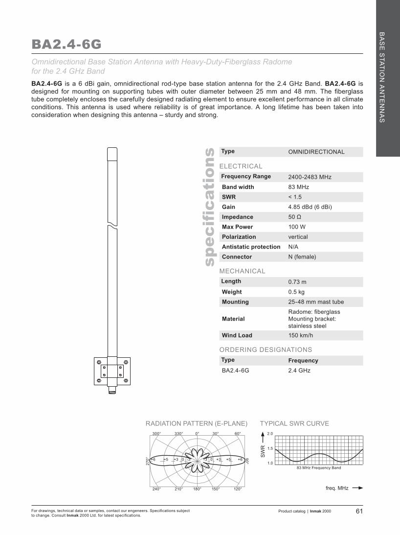
TYPICAL SWR CURVE
SW
R
freq. MHz
1.0
2.0
1.5
RADIATION PATTERN (E-PLANE)0°
180°
330°300°
90°
60°30°
210°240° 120°150°
270° 0+6 +5 +3 -3 +5 -3 0 +3 +6
Product catalog | Inmak 2000 61For drawings, technical data or samples, contact our engeneers. Specifications subject to change. Consult Inmak 2000 Ltd. for latest specifications.
spec
ification
s
BA
SE
STATIO
N A
NT
EN
NA
S
83 MHz Frequency Band
BA2.4-6G
BA2.4-6G is a 6 dBi gain, omnidirectional rod-type base station antenna for the 2.4 GHz Band. BA2.4-6G is designed for mounting on supporting tubes with outer diameter between 25 mm and 48 mm. The fiberglass tube completely encloses the carefully designed radiating element to ensure excellent performance in all climate conditions. This antenna is used where reliability is of great importance. A long lifetime has been taken into consideration when designing this antenna – sturdy and strong.
Type OMNIDIRECTIONAL
ELECTRICALFrequency Range 2400-2483 MHz
Band width 83 MHz
SWR < 1.5
Gain 4.85 dBd (6 dBi)
Impedance 50 Ω
Max Power 100 W
Polarization vertical
Antistatic protection N/A
Connector N (female)
MECHANICALLength 0.73 m
Weight 0.5 kg
Mounting 25-48 mm mast tube
MaterialRadome: fiberglassMounting bracket: stainless steel
Wind Load 150 km/h
ORDERING DESIGNATIONSType FrequencyBA2.4-6G 2.4 GHz
Omnidirectional Base Station Antenna with Heavy-Duty-Fiberglass Radomefor the 2.4 GHz Band
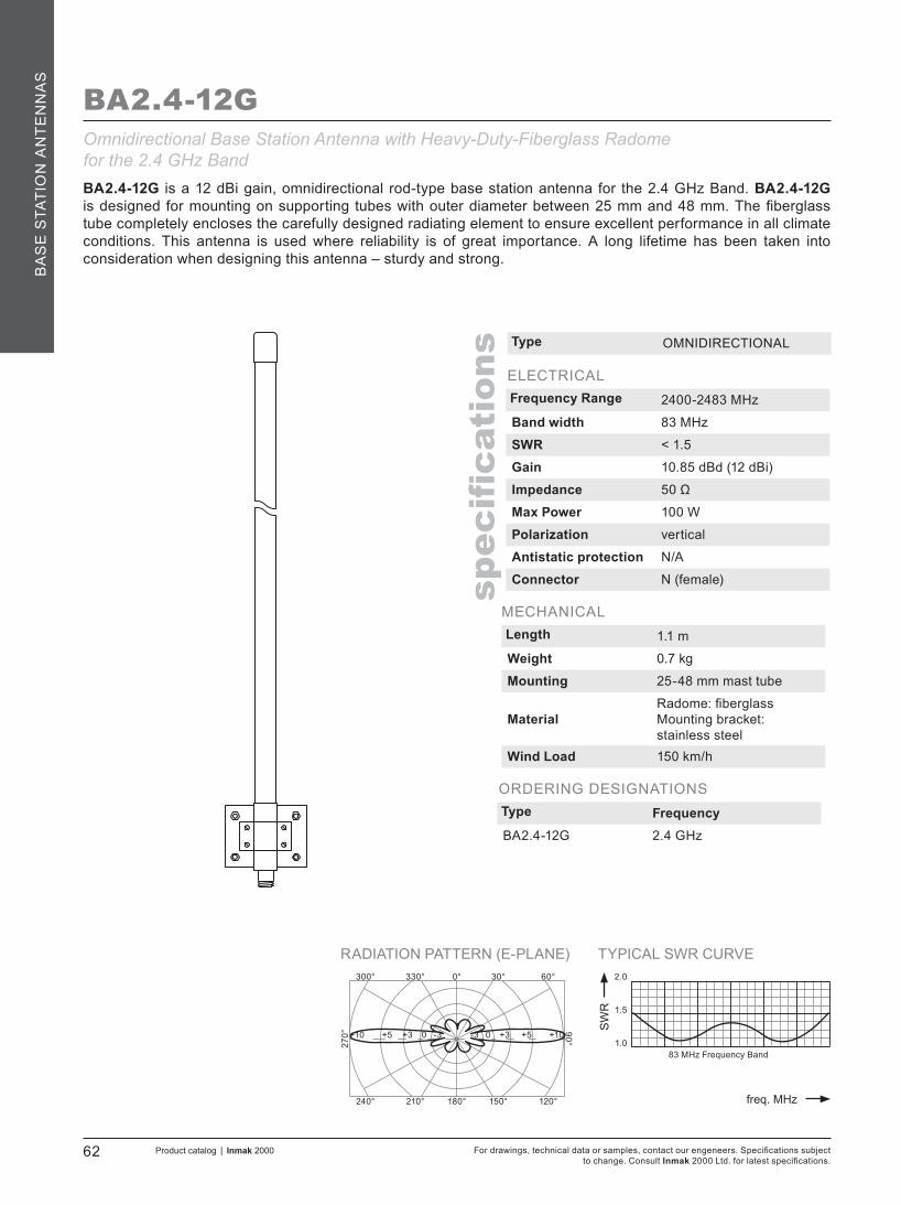
TYPICAL SWR CURVE
SW
R
freq. MHz
1.0
2.0
1.5
RADIATION PATTERN (E-PLANE)0°
180°
330°300°
90°
60°30°
210°240° 120°150°
270° 0+10 +5 +3 -3 +5-3 0 +3 +10
83 MHz Frequency Band
For drawings, technical data or samples, contact our engeneers. Specifications subject to change. Consult Inmak 2000 Ltd. for latest specifications.
62 Product catalog | Inmak 2000
spec
ification
s
BA
SE
STA
TIO
N A
NT
EN
NA
S
BA2.4-12G
BA2.4-12G is a 12 dBi gain, omnidirectional rod-type base station antenna for the 2.4 GHz Band. BA2.4-12G is designed for mounting on supporting tubes with outer diameter between 25 mm and 48 mm. The fiberglass tube completely encloses the carefully designed radiating element to ensure excellent performance in all climate conditions. This antenna is used where reliability is of great importance. A long lifetime has been taken into consideration when designing this antenna – sturdy and strong.
Type OMNIDIRECTIONAL
ELECTRICALFrequency Range 2400-2483 MHz
Band width 83 MHz
SWR < 1.5
Gain 10.85 dBd (12 dBi)
Impedance 50 Ω
Max Power 100 W
Polarization vertical
Antistatic protection N/A
Connector N (female)
MECHANICALLength 1.1 m
Weight 0.7 kg
Mounting 25-48 mm mast tube
MaterialRadome: fiberglassMounting bracket: stainless steel
Wind Load 150 km/h
ORDERING DESIGNATIONSType FrequencyBA2.4-12G 2.4 GHz
Omnidirectional Base Station Antenna with Heavy-Duty-Fiberglass Radomefor the 2.4 GHz Band
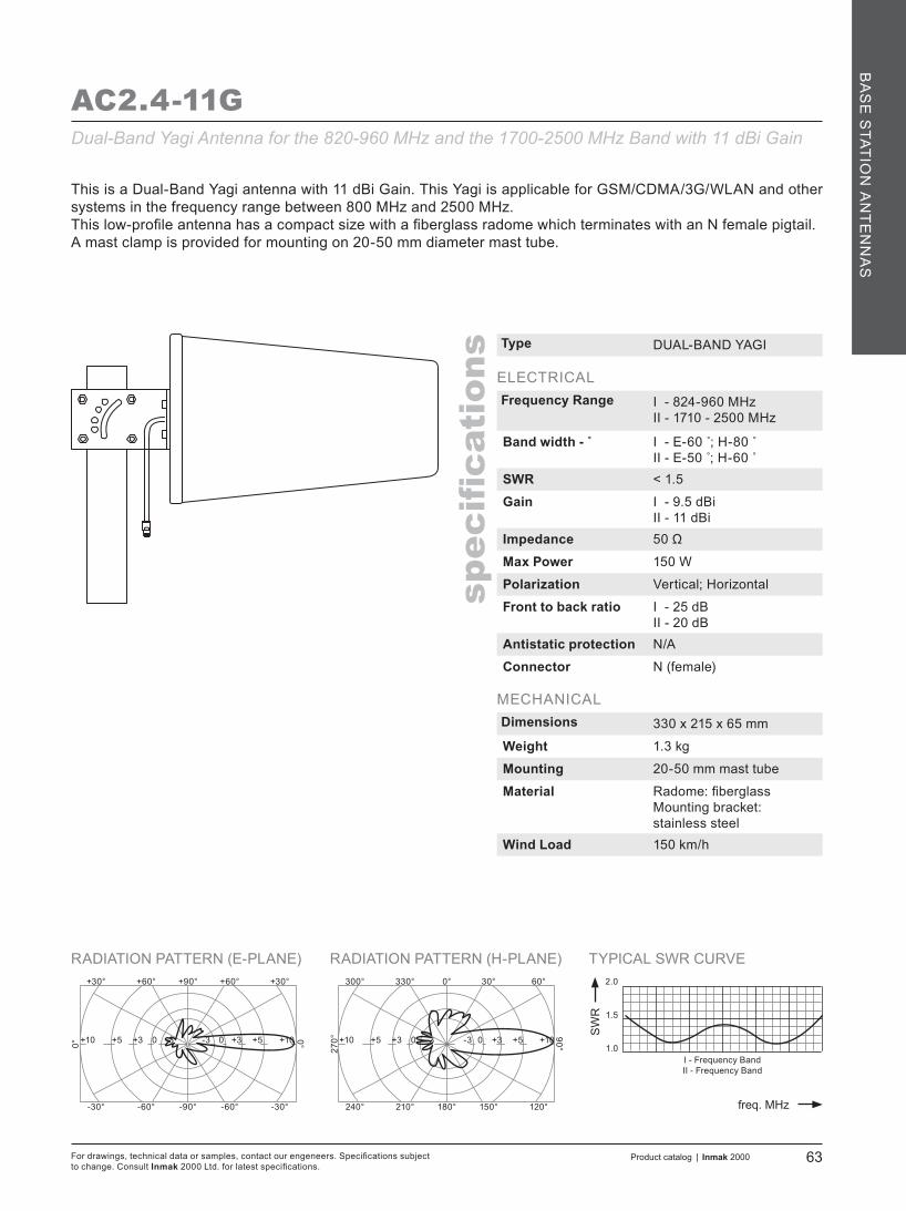
TYPICAL SWR CURVE
SW
R
freq. MHz
1.0
2.0
1.5
RADIATION PATTERN (E-PLANE) RADIATION PATTERN (H-PLANE)+90°
-90°
+60°+30°
0°
+30°+60°
-60°-30° -30°-60°
0°
0°
180°
330°300°
90°
60°30°
210°240° 120°150°
270°0+10 +5 +3 -3 +5-3 0 +3 +10 0+10 +5 +3 -3 +5-3 0 +3 +10
I - Frequency BandII - Frequency Band
Product catalog | Inmak 2000 63For drawings, technical data or samples, contact our engeneers. Specifications subject to change. Consult Inmak 2000 Ltd. for latest specifications.
spec
ification
s
BA
SE
STATIO
N A
NT
EN
NA
S
AC2.4-11GDual-Band Yagi Antenna for the 820-960 MHz and the 1700-2500 MHz Band with 11 dBi Gain
This is a Dual-Band Yagi antenna with 11 dBi Gain. This Yagi is applicable for GSM/CDMA/3G/WLAN and other systems in the frequency range between 800 MHz and 2500 MHz.This low-profile antenna has a compact size with a fiberglass radome which terminates with an N female pigtail.A mast clamp is provided for mounting on 20-50 mm diameter mast tube.
Type DUAL-BAND YAGI
ELECTRICALFrequency Range I - 824-960 MHz
II - 1710 - 2500 MHz
Band width - ˚ I - E-60 ;̊ H-80 ˚II - E-50 ;̊ H-60 ˚
SWR < 1.5
Gain I - 9.5 dBiII - 11 dBi
Impedance 50 Ω
Max Power 150 W
Polarization Vertical; Horizontal
Front to back ratio I - 25 dBII - 20 dB
Antistatic protection N/A
Connector N (female)
MECHANICALDimensions 330 x 215 x 65 mm
Weight 1.3 kg
Mounting 20-50 mm mast tube
Material Radome: fiberglassMounting bracket: stainless steel
Wind Load 150 km/h

TYPICAL SWR CURVE
SW
R
freq. MHz
1.0
2.0
1.5
RADIATION PATTERN (E-PLANE) RADIATION PATTERN (H-PLANE)+90°
-90°
+60°+30°
0°
+30°+60°
-60°-30° -30°-60°
0°
0°
180°
330°300°
90°
60°30°
210°240° 120°150°
270°
83 MHz Frequency Band
+6+24 +18 +12 0 +180 +6 +12 +24 +6+24 +18 +12 0 +180 +6 +12 +24
For drawings, technical data or samples, contact our engeneers. Specifications subject to change. Consult Inmak 2000 Ltd. for latest specifications.
64 Product catalog | Inmak 2000
spec
ification
s
BA
SE
STA
TIO
N A
NT
EN
NA
S
ACP2.4-24G
ACP2.4-24G is a 24 dBi gain, wire grid parabolic base station antenna for the 2.4 GHz Band. Due to its grid parabolic reflector the ACP2.4-24G attains wide band width and strong gain. Constructed of welded steel wires which are galvanized and then powder coat painted, they offer extremely long service life in the most extreme environmental conditions. The wire grid semi-parabolic design offers unsurpassed low wind loading while maintaining good RF performance. The antenna is designed for mounting on supporting tubes with outer diameter between 30 mm and 50 mm. It can be mounted for both vertical and horizontal polarization. The antenna terminates with an N female connector.
Type Wire Grid Parabolic
ELECTRICALFrequency Range 2400-2483 MHz
Band width 83 MHz
SWR < 1.5
Gain 24 dBi
Impedance 50 Ω
Max Power 100 W
Polarization Vertical; Horizontal
Front to back ratio 31 dB
Antistatic protection DC-grounded (Connector shows a DC-short)
Connector N (female)
MECHANICALDimensions 900 x 600 mm
Weight 2.50 kg
Mounting 30-50 mm mast tube
Material Powder coated steel
Wind Load 150 km/h
ORDERING DESIGNATIONSType FrequencyACP2.4-24G 2.4 GHz
Parabolic Grid Directional Antenna for the 2.4 GHz Band

TYPICAL SWR CURVE
SW
R
freq. MHz
1.0
2.0
1.5
RADIATION PATTERN (E-PLANE)0°
180°
330°300°
90°
60°30°
210°240° 120°150°
270°
Product catalog | Inmak 2000 65For drawings, technical data or samples, contact our engeneers. Specifications subject to change. Consult Inmak 2000 Ltd. for latest specifications.
spec
ification
s
BA
SE
STATIO
N A
NT
EN
NA
S
0+10 +5 +3 -3 +5-3 0 +3 +10
125 MHz Frequency Band
BA5.8-12G
BA5.8-12G is a 12 dBi gain, omnidirectional rod-type base station antenna for the 5.8 GHz Band. BA5.8-12G is designed for mounting on supporting tubes with outer diameter between 25 mm and 48 mm. The fiberglass tube completely encloses the carefully designed radiating element to ensure excellent performance in all climate conditions. This antenna is used where reliability is of great importance. A long lifetime has been taken into consideration when designing this antenna – sturdy and strong.
Type OMNIDIRECTIONAL
ELECTRICALFrequency Range 5725-5850 MHz
Band width 125 MHz
SWR < 1.5
Gain 10.85 dBd (12 dBi)
Impedance 50 Ω
Max Power 100 W
Polarization vertical
Antistatic protection N/A
Connector N (female)
MECHANICALLength 0.54 m
Weight 0.5 kg
Mounting 25-48 mm mast tube
MaterialRadome: fiberglassMounting bracket: stainless steel
Wind Load 150 km/h
ORDERING DESIGNATIONSType FrequencyBA5.8-12G 5.8 GHz
Omnidirectional Base Station Antenna with Heavy-Duty-Fiberglass Radomefor the 5.8 GHz Band

TYPICAL SWR CURVE
SW
R
freq. MHz
1.0
2.0
1.5
RADIATION PATTERN (E-PLANE) RADIATION PATTERN (H-PLANE)+90°
-90°
+60°+30°
0°
+30°+60°
-60°-30° -30°-60°
0°
0°
180°
330°300°
90°
60°30°
210°240° 120°150°
270°
125 MHz Frequency Band
ACP5.8-24G
ACP5.8-24G is a 27 dBi gain, wire grid parabolic base station antenna for the 5.8 GHz Band. Due to its grid parabolic reflector the ACP5.8-24G attains wide band width and strong gain. Constructed of welded steel wires which are galvanized and then powder coat painted, they offer extremely long service life in the most extreme environmental conditions. The wire grid semi-parabolic design offers unsurpassed low wind loading while maintaining good RF performance. The antenna is designed for mounting on supporting tubes with outer diameter between 30 mm and 50 mm. It can be mounted for both vertical and horizontal polarization. The antenna terminates with an N female connector.
Type Wire Grid Parabolic
ELECTRICALFrequency Range 5725-5850 MHz
Band width 125 MHz
SWR < 1.5
Gain 27 dBi
Impedance 50 Ω
Max Power 100 W
Polarization Vertical; Horizontal
Front to back ratio 25 dB
Antistatic protection DC-grounded (Connector shows a DC-short)
Connector N (female)
MECHANICALDimensions 600 x 400 mm
Weight 2.40 kg
Mounting 30-50 mm mast tube
Material Powder-coated steel
Wind Load 150 km/h
ORDERING DESIGNATIONSType FrequencyACP5.8-24G 5.8 GHz
Parabolic Grid Directional Antenna for the 5.8 GHz Band
+6+24 +18 +12 0 +180 +6 +12 +24 +6+24 +18 +12 0 +180 +6 +12 +24
For drawings, technical data or samples, contact our engeneers. Specifications subject to change. Consult Inmak 2000 Ltd. for latest specifications.
66 Product catalog | Inmak 2000
spec
ification
s
BA
SE
STA
TIO
N A
NT
EN
NA
S

NOTES


![files.tendacn.com · Web view[PC] Hướng dẫn cài đặt Tenda AC5 v3 ở chế độ Repeater (thu sóng WiFi phát lại)Kết nối với WiFi mặc định của Tenda AC5](https://img.pdfslide.net/doc/110x75/609969b9b24e690fa139cfb1/files-web-view-pc-hng-dn-ci-t-tenda-ac5-v3-ch-repeater.jpg)


![HÁZI ÉS EGYEDI NYOMÁSSZABÁLYOZÓK EKB család 10, 25, 40, … · 2016-04-28 · VF100 teljesítménye SG20 AC5 AC5 20 22 24 26 28 30 32 34 36 0 20 40 60 80 100 p a [ ] Qgaz [](https://img.pdfslide.net/doc/110x75/5f1f4188b71ba71164579ad3/hzi-s-egyedi-nyomsszablyozk-ekb-csald-10-25-40-2016-04-28-vf100.jpg)