Embed Size (px)
Citation preview

Th ermostats, diff erential thermostats Type RT
REFRIGERATION AND AIR CONDITIONING
Technical leafl et

Technical leafl et Thermostats, diff erential thermostats, type RT
© Danfoss A/S (IC-MC/mb), 11 - 2004 RD.5E.A4.02 2
Technical leafl et Thermostats, diff erential thermostats, type RT
© Danfoss A/S (IC-MC/mb), 11 - 2004 RD.5E.A4.02 3
Contents Page
Introduction . . . . . . . . . . . . . . . . . . . . . . . . . . . . . . . . . . . . . . . . . . . . . . . . . . . . . . . . . . . . . . . . . . . . . . . . . . . . . . . . . . . . . . 4
Features . . . . . . . . . . . . . . . . . . . . . . . . . . . . . . . . . . . . . . . . . . . . . . . . . . . . . . . . . . . . . . . . . . . . . . . . . . . . . . . . . . . . . . . . . . 4
Technical data . . . . . . . . . . . . . . . . . . . . . . . . . . . . . . . . . . . . . . . . . . . . . . . . . . . . . . . . . . . . . . . . . . . . . . . . . . . . . . . . . . . . . 4
Approvals . . . . . . . . . . . . . . . . . . . . . . . . . . . . . . . . . . . . . . . . . . . . . . . . . . . . . . . . . . . . . . . . . . . . . . . . . . . . . . . . . . . . . . . . . 5
Overview . . . . . . . . . . . . . . . . . . . . . . . . . . . . . . . . . . . . . . . . . . . . . . . . . . . . . . . . . . . . . . . . . . . . . . . . . . . . . . . . . . . . . . . . . 5
Ordering . . . . . . . . . . . . . . . . . . . . . . . . . . . . . . . . . . . . . . . . . . . . . . . . . . . . . . . . . . . . . . . . . . . . . . . . . . . . . . . . . . . . . . . . 6-7
Design/ Function, RT thermostat . . . . . . . . . . . . . . . . . . . . . . . . . . . . . . . . . . . . . . . . . . . . . . . . . . . . . . . . . . . . . . . . . . . 8
Design/ Function, thermostats with neutral zone type RTL . . . . . . . . . . . . . . . . . . . . . . . . . . . . . . . . . . . . . . . . . . 9
Charges . . . . . . . . . . . . . . . . . . . . . . . . . . . . . . . . . . . . . . . . . . . . . . . . . . . . . . . . . . . . . . . . . . . . . . . . . . . . . . . . . . . . . . . 10-11
Design/ Function, diff erential thermostats type RT . . . . . . . . . . . . . . . . . . . . . . . . . . . . . . . . . . . . . . . . . . . . . . . . 12
Setting of diff erential . . . . . . . . . . . . . . . . . . . . . . . . . . . . . . . . . . . . . . . . . . . . . . . . . . . . . . . . . . . . . . . . . . . . . . . . . . . . . 13
Nomograms for obtained diff erentials . . . . . . . . . . . . . . . . . . . . . . . . . . . . . . . . . . . . . . . . . . . . . . . . . . . . . . . . . . . . 13
Dimensions and weight . . . . . . . . . . . . . . . . . . . . . . . . . . . . . . . . . . . . . . . . . . . . . . . . . . . . . . . . . . . . . . . . . . . . . . . . . . 14

Technical leafl et Thermostats, diff erential thermostats, type RT
© Danfoss A/S (IC-MC/mb), 11 - 2004 RD.5E.A4.02 4
Introduction An RT thermostat is fi tted with a single-pole changeover switch.The position of the contacts depends on the bulb temperature and the set scale value.The RT series includes thermostats for general applications within industrial and marine refrigeration.The RT series also includes diff erential thermostats, thermostats for neutral zone regulation, and special thermostats with gold-plated contact surface for PLC applications.
Features Waterproof versions, enclosure IP 66
Wide regulating range
Wide range of units for industrial and marine applications
Suitable for alternating and direct current
Interchangeable contact system
Special versions for PLC applications
Technical data Cable connectionPg 13.5. Cable diameter 6 → 14 mm.
EnclosureIP 66 to EN 60529 / IEC 60529, except for versions with ext. reset which are to IP 54.
Properties according to EN 60947:Wire dimensions solid/stranded 0.2 - 2.5 mm2
fl exible, w/out ferrules 0.2 - 2.5 mm2
fl exible, with ferrules 0.2 - 1.5 mm2
Tightening torque max. 1.5 NMRated impulse voltage 4 kVPollution degree 3Short circuit protection, fuse 10 AmpInsulation 400 VIP 54/66
Permissible ambient temperature−50 → +70°C for thermostat housing.
SwitchesSee "Ordering switches".

Technical leafl et Thermostats, diff erential thermostats, type RT
© Danfoss A/S (IC-MC/mb), 11 - 2004 RD.5E.A4.02 5
−50 0 +50 +100 +150 +200 +250 +300°C Range °C Type
−60 → -25 RT 10
Vapour-charged with remote bulb(bulb coldest)
−45 → −15 RT 9
−30 → 0 RT 13
−25 → +15 RT 3
−25 → +15 RT 2, 7
−20 → +12 RT 8
−5 → +10 RT 12
−5 → +30 RT 14
Adsorption-charged with remote bulb(bulb warmest or coldest)
+5 → +22 RT 23
+8 → +32 RT 15
+15 → +34 RT 24
+15 → +45 RT 140
+25 → +90 RT 101, 102
Partial charge with remote bulb (bulb warmest) +70 → +150 RT 107
−50 → −15 RT 17
Vapour-charged with coiled capillary tube sensor(room thermostats)
−30 → 0 RT 11
−5 → +30 RT 4
Adsorption-charged with coiled capillary tube sensor (room thermostats) −25 → +15 RT 34
−20 → +12 RT 8L
Adsorption-charged dead zone thermostats with remote bulb(bulb warmest or coldest)
−5 → +30 RT 14L
+15 → +45 RT 140L
Vapour-charged dead zone thermostat (room thermostat) 0 → +38 RT 16L
Adsorption-charged diff erential thermostats with remote bulb (bulb warmest or coldest) −30 → +40 RT 270
−50 0 +50 +100 +150 +200 +250 +300°C
Approvals
RT 2
RT 3
RT 4
RT 7
RT 8
RT 8
L
RT 9
RT 1
0
RT 1
1
RT 1
2
RT 1
3
RT 1
4
RT 1
4L
RT 1
5
RT 1
6L
RT 1
7
RT 2
3
RT 2
4
RT 3
4
RT 1
01
RT 1
02
RT 1
07
RT 1
40
RT 1
40L
RT 2
70
• Lloyd’s Reg. of Shipping, UK
• • • • • • • • • • • • • Germanischer Lloyd, Germany
• Det norske Veritas, Norway
• Bureau Veritas, France
• • • • • • • • • • • • • • • • • • • RINA, Registro Italiano Navale, Italy
• • • • • • • • • • • • • • • • • • • • • • • • • RMRS Russian Maritime Register of Shipping
• • • • • • • • • • • • • NKK, Japan
• Korean Register of Shipping, Korea
• • • • • • • • • • • • • • • • • • • • • • • • • Conformity with EN 60730-2-1 to 9
• • • • • • • • • • • • • • • • • • • • • • • • • CE mark according to EN 60947-4, -5
• • • • • • • • • • • • • • • • • • • • • • • • • CCC, China Compulsory Certifi cate
Overview

Technical leafl et Thermostats, diff erential thermostats, type RT
© Danfoss A/S (IC-MC/mb), 11 - 2004 RD.5E.A4.02 6
Charge Type Bulbtype
Regulationrange
°C
Diff erential ∆ t Reset Max.bulb
temp.
°C
Capillarytube
length
m
Code no.
Lowesttemp.
settingK
Highesttemp.
settingK
Vapour 1)
RT 10 A −60 → −25 1.7→ 7.0 1.0→ 3.0 aut. 150 2 017-507766
RT 9 A −45 → −15 2.2→10.0 1.0→ 4.5 aut. 150 2 017-506666
RT 3 A −25 → +15 2.8→10.0 1.0→ 4.0 aut. 150 2 017-501466
RT 17 B −50 → −15 2.2→ 7.0 1.5→ 5.0 aut. 100 017-511766
RT 11 B −30 → 0 1.5→ 6.0 1.0→ 3.0 aut. 66 017-508366
RT 4 B −5 → +30 1.5→ 7.0 1.2→ 4.0 aut. 75 017-5036 66 017-5037664)
Adsorp-tion 2)
RT 13 A −30 → 0 1.5→ 6.0 1.0→ 3.0 aut. 150 2 017-509766
RT 2 A −25 → +15 5.0→18.0 6.0→20.0 aut. 150 2 017-500866
RT 8 A −20 → +12 1.5→ 7.0 1.5→ 7.0 aut. 145 2 017-506366
RT 12 A −5 → +10 1.0→ 3.5 1.0→ 3.0 aut. 65 2 017-508966
RT 23 A +5 → +22 1.1→ 3.5 1.0→ 3.0 aut. 85 2 017-527866
RT 15 A +8 → +32 1.6→ 8.0 1.6→ 8.0 aut. 150 2 017-511566
RT 24 A +15 → +34 1.4→ 4.0 1.4→ 3.5 aut. 105 2 017-528566
RT 140 C +15 → +45 1.8→ 8.0 2.5→11.0 aut. 240 2 017-523666
RT 102 D +25 → +90 2.4→10.0 3.5→20.0 aut. 300 2 017-514766
RT 34 B −25 → +15 2.0→10.0 2.0→12.0 aut. 100 017-511866
RT 7 A −25 → +15 2.0→10.0 2.5→14.0 aut. 150 2 017-505366
RT 14 A −5 → +30 2.0→ 8.0 2.0→10.0 aut. 150 2 017-509966
RT 101 A +25 → +90 2.4→10.0 3.5→20.0 aut. 300 2 017-500366
Partial 3) RT 107 A +70 → +150 6.0→25.0 1.8→ 8.0 aut. 215 2 017-513566
Charge Type Bulb type
Regulationrange
°C
Diff eren-tial
K
Dead zone NZ Max.bulb
temp.
°C
Capillarytube
length
m
Code no.
Lowesttemp.
settingK
Highesttemp.
settingK
Vapour RT 16L B 0 → +38 1.5 / 0.7 1.5 → 5.0 0.7 → 1.9 100 017L002466
Adsorp-tion
RT 8L A −20 → +12 1.5 1.5 → 4.4 1.5 → 4.9 145 2 017L003066
RT 14L A −5 → +30 1.5 1.5 → 5.0 1.5 → 5.0 150 2 017L003466
RT 140L C +15 → +45 1.8 / 2.0 1.8 → 4.5 2.0 → 5.0 240 2 017L003166
RT 101L A +25 → +90 2.5 / 3.5 2.5 → 7.0 3.5 → 12.5 300 2 017L006266
A B C D
Ordering Thermostats
1) The sensor must be located colder than thermostat housing and capillary tube. 2) The sensor can be located warmer or colder than thermostat housing. 3) The sensor must be located warmer than thermostat housing and capillary tube.4) With built-in heating coil − reduces the thermal diff erential.
Thermostats with adjustable dead zone
Type of bulb / sensor
Cylindrical Room sensor Duct sensor Capillary remote sensor tube sensor
Special versionsRT can be supplied with special switches.See next page.
When ordering, please state1. Type2. Code no. of standard unit3. Code no. of special switch

Technical leafl et Thermostats, diff erential thermostats, type RT
© Danfoss A/S (IC-MC/mb), 11 - 2004 RD.5E.A4.02 7
Version Symbol Description Contact rating Reset Code no.
Standard
SPDT
Single-pole changeover switch with terminal board proof against leakage current. Fitted in all standard versions of type RT. Snap action changeover contacts.
Alternating current
Ohmic: AC1 = 10 A, 400 V
Inductive: AC3 = 4 A, 400 VAC15 = 3 A, 400 V
Dir. current: DC13 = 12 W, 220 V
Aut.
017-403066
Man. reset
SPDT
For manual reset of unit after contact changeover on rising temperature. For units with reset facility.
Max. 017-404266
Man. reset
SPDT
For manual reset of unit after contact changeover on falling temperature. For units with reset facility.
Min. 017-404166
Dead zone
SPDT
Single-pole changeover switch with dead zone and terminal board proof against leakage current.
Available only as a componentpart of RTcontrols withadjustabledead zone
Standard
SPDT
Single-pole changeover switch with gold plated (oxide-free) contact surfaces. Increases cut-in reliability on alarm and monitoring systems, etc. Snap action changeover contacts. Terminal board proof against leakage current.
Alternating current
Ohmic: AC1 = 10 A, 400 V
Inductive: AC3 = 2 A, 400 V AC15 = 1 A, 400 V
Dir. current: DC13 = 12 W, 220 V
Aut. 017-424066
Man. reset
SPDT
Single-pole changeover switch with gold plated (oxide-free) contact surfaces. Increases cut-in reliability on alarm and monitoring systems, etc. Snap action changeover contacts. Terminal board proof against leakage current.
Max. 017-404866
Dead zone
SPDT
Single-pole changeover switch with dead zone and gold plated (oxide-free) contact surfaces. Increase cut-in reliability on alarm and monitoring systems, etc. Snap action changeover contacts. Terminal board proof against leakage current.
Availableonly as acomponentpart of RTcontrols withadjustabledead zone
Man. reset
SPDT
Single-pole changeover switch with gold plated (oxide-free) contact surfaces. Increases cut-in reliability on alarm and monitoring systems, etc. Snap action changeover contacts. Terminal board proof against leakage current.
Min. 017-404766
Cuts in two circuits simultane-ously SPST
Single-pole changeover switch that cuts in two circuits simultaneously on rising temperature. Snap action changeover contacts. Terminal board proof against leakage current.
Alternating current
Ohmic: AC1 = 10 A, 400 V
Inductive: AC3 = 3 A, 400 V AC15 = 2 A, 400 V
Dir. current: DC13 = 12 W, 220 V 1)
Max. 017-403466
Cuts out two circuitssimultane-ously SPST
Single-pole changeover switch that cuts out two circuits simultaneously on rising temperature. Snap action changeover contacts. Terminal board proof against leakage current.
Min.
017-403666
With non-snap action change- over contacts
SPDT
Single-pole changeover switch with non-snap action changeover contacts.
Alternating or direct current 25 VA, 24 V
017-018166
Ordering(continued)
1) If current is led through contacts 2 and 4, i.e. terminals 2 and 4 connected but not 1, max. permissible load is increased to 90 W, 220 V.
The switches are shown in the position they assume on falling temperature, i.e. after downward movement of the RT main spindle.The setting pointer of the control shows the scale value at which contact changeover occurs on falling temperature.
An exception is RT with switch, code no. 017-404266, with max. reset where the setting pointer shows the scale value at which contact changeover occurs on rising temperature.
Spare parts and accessories, see spare parts catalogue RX.5E.A2.02.
Switches

Technical leafl et Thermostats, diff erential thermostats, type RT
© Danfoss A/S (IC-MC/mb), 11 - 2004 RD.5E.A4.02 8
DesignFunction
Thermostat type RT
5. Setting knob 9. Regulation range scale10. Loop terminal11. Pg 13.5 screwed cable entry12. Main spring14. Terminals15. Main spindle16. Switch 17. Upper guide bush18. Contact arm19. Diff erential temperature setting nut 23. Bellows element25. Fixing hole26. Sensor (bulb) clip28. Capillary tube29. Sensor (bulb)30. Sensor (bulb) pocket31. Capillary tube gland38. Earth terminal44. Temperature setting spindle
The thermostatic element consists of a sensor (29) capillary tube (28) and bellows element (23).The element contains a charge that reacts to temperature variations at the sensor so that the pressure on the moving bellows rises when temperature rises.By turning the setting knob (5) the main spring (12) can be set to balance the pressure in theelement.
Key sketch of RT thermostat
RT thermostat
A rise in temperature at the sensor compresses the bellows and moves the main spindle (15) upwards until spring force and element pressure are in equilibrium.The main spindle (15) is fi tted with a guide bush (17) and a diff erential setting nut (19) that together transfer the main spindle movement to the switch (16).

Technical leafl et Thermostats, diff erential thermostats, type RT
© Danfoss A/S (IC-MC/mb), 11 - 2004 RD.5E.A4.02 9
DesignFunction(continued)
Thermostats with neutral zone, type RT L
5. Setting knob 9. Regulation range scale12. Main spring15. Main spindle16. Switch17. Upper guide bush18a and 18b. Contact arm20. Lower guide bush23. Bellows element25. Fixing hole28. Capillary tube29. Sensor (bulb)40. Neutral zone setting nut44. Temperature setting spindle
Key sketch RT L thermostat
RT L thermostat
RT L pressure controls are fi tted with a switch (17-4032) with an adjustable neutral zone. This enables the units to be used for fl oating control.The neutral zone switch contact arms (18a) and (18b) are operated by the spindle guide bushes (17) and (20). The upper guide bush (17) is fi xed
while the lower guide bush (20) can be moved up or down by the setting nut (40). In this way the neutral zone can be varied between a minimum value (equal to the mechanical diff erential of the unit) and a maximum value (depending on the type of RT unit).
Terminology Floating controlA form of delayed control where the correcting element (e.g. valve, damper, or similar) moves towards one extreme position at a rate independent of the magnitude of the error when the error exceeds a defi nite positive value, and towards the opposite extreme position when the error exceeds a defi nite negative value.
HuntingPeriodic variations of the controlled variable from the fi xed reference.
Neutral zoneThe interval between the make points of the two contacts.

Technical leafl et Thermostats, diff erential thermostats, type RT
© Danfoss A/S (IC-MC/mb), 11 - 2004 RD.5E.A4.02 10
TypeRegulating
range °C
Correctionfactor
a
RT 2 RT 7 RT 8, RT 8L RT 12 RT 14, RT 14L RT 15 RT 23 RT 24 RT 101, RT 102 RT 140, RT 140L
−25 → +15°C −25 → +15°C −20 → +12°C −5 → +10°C −5 → +30°C +8 → +32°C +5 → +22°C +15 → +34°C +25 → +90°C +15 → +45°C
2.3 2.91.71.22.41.20.60.85.03.1
Charges 1. Vapour chargeThis principle can be utilized in thermostats for low temperature, etc., where evaporation must be able to take place from the free liquid surface in the bulb (within the operation range of the thermostat), and where at the same time, the bellows must be protected against deformation when kept at normal ambient temperatures.Since the pressure in the element depends on the temperature at the free liquid surface, the thermostat must always be placed so that the bulb is colder than the rest of the thermostatic element.The evaporated liquid will recondense at the coldest point, i.e. the bulb. Thus, as intended, the bulb becomes the temperature-controlling element in the system.
Note: When the bulb is coldest, the ambient temperature has no eff ect on regulating accuracy.
Here the interdependence between the pressure and temperature of saturated vapour is utilized, i.e. the element is charged with saturated vapour plus a small amount of liquid.The charge is pressure-limited; a further increase in pressure after evaporation of all the liquid in the bulb, will only result in a small pressure increase in the element.
2. Adsorption charge
In this case the charge consists partly of a superheated gas and partly of a solid having a large adsorption surface.The solid is concentrated in the bulb and it is therefore always the bulb that is the temperature-controlling part of the thermostatic element.The bulb can thus be placed warmer or colder than the rest of the thermostatic element.Such a charge is however to some extent sensitive to changes in the temperature of the bellows element and capillary tube. Under normal conditions this is not important, but if the thermostat is used in extreme conditions, scale deviation will occur. The scale can be corrected by using the graph and the table.Scale correction = Z × a.Z can be found in the graph and "a" in the table.
Relativescalesetting (%)
Scale deviationfactor
Curves for diff erent ambient temperatures.0% ~ lowest scale setting temperature,100% ~ highest scale setting temperature.

Technical leafl et Thermostats, diff erential thermostats, type RT
© Danfoss A/S (IC-MC/mb), 11 - 2004 RD.5E.A4.02 11
Charges(continued)
ExampleScale correction on an RT 14 (range −5 to +30°C) at activating temperature +12°C and ambient temperature −10°C.The scale temperature, +12°C, lies approximately in the middle of the scale range, i.e. relative scale setting of 50%.The factor Z can be found in the graph from 50% and the curve for −10°C, i.e. approx. −1.2.
The correction factor "a" can be found in the table for an RT 14, i.e. 2.4.The scale correction = Z × a = −1.2 × 2.4 = −2.88.If activation at +12°C for the same conditions is required, the thermostat must be set at +12 × 2.88 = 9.12 ≈ 9.1.
3. Partial charge
Partial charge is used in RT units having a range lying higher than ambient temperature.
As with the vapour charge, the partial charge utilizes the interdependence between the pressure and temperature of saturated vapour.The partial charge is of such a volume that the bellows housing, capillary tube and a small part of the bulb are fi lled when the thermostat is in operation. The bulb is thus the warmest part of the system.The liquid will condense in the remaining, coldest, part of the system but because of the volume of the charge the free liquid surface will always be in the bulb. In this way, the bulb becomes the temperature-controlling part of the system.
Note: When the bulb is placed warmest, the ambient temperature has no eff ect on regulating accuracy.

Technical leafl et Thermostats, diff erential thermostats, type RT
© Danfoss A/S (IC-MC/mb), 11 - 2004 RD.5E.A4.02 12
1. LT sensor (bulb) 2. Capillary tube 4. LT bellows element 5. Setting disc 9. Regulation range scale10. Loop terminal11. Pg 13.5 screwed cable entry12. Main spring14. Terminals15. Main spindle16. Switch 17. Upper guide bush18. Contact arm20. Lower guide bush24. HT bellows element25. Fixing hole28. Capillary tube32. HT sensor (bulb)38. Earth terminal39. Blow-out disc
DesignFunction
RT diff erential thermostatAn RT diff erential thermostat contains a single-pole changeover switch that makes or breaks depending on the temperature diff erence between the two sensors of the unit.The RT 270 is for use in process plant, ventilation plant, and refrigeration and heating plant where there is need to maintain a certain temperature diff erential, 0 - 15°C, between two media. One sensor is used as a reference and the other as a control sensor. The temperature diff erential is the direct controlled variable.
The fi gure shows a cross-section of the RT 270.
The diff erential thermostat contains two bellows elements: the LT element whose sensor must be placed in the medium having the lowest temperature, and the HT element whose sensor must be placed in the medium having the highest temperature.The main spring has a rectilinear characteristic. Within the operating range the RT 270 can be set for diff erent temperature diff erentials by the setting disc (5).When the diff erential between LT and HT sensor temperature falls, the main spindle (15) moves downwards. The contact arm (18) is moved downwards by the guide (17) so that contacts (1-4) break and contacts (1-2) make when the set temperature diff erential is reached.The contacts changeover again when the temperature diff erential rises to the set value plus the fi xed contact diff erential of approx. 2°C.
ExampleSet diff erential = 4°C.Switch breaks at 4°C diff erential and remakes at 4 + 2 = 6°C.
RT diff erential thermostat
Terminology Regulation rangeThe temperature diff erential between LT and HT sensors within which the unit can be set to operate. Indicated on the thermostat scale.
Scale indicationThe diff erence between the temperature on LT and HT sensors at the moment when the switch contacts change over as a result of the downward movement of the spindle.
Operating rangeThe temperature range of the LT sensor, within which the diff erential thermostat can operate.
Contact diff erentialThe temperature rise on the HT sensor over the set temperature diff erential which causes the switch contacts to make or break.
Reference sensorThe sensor that is placed in the medium whose temperature is not aff ected by the function of the thermostat (HT- or LT sensor).
Control sensorThe sensor that is placed in the medium whose temperature must be controlled (LT- or HT sensor).

Technical leafl et Thermostats, diff erential thermostats, type RT
© Danfoss A/S (IC-MC/mb), 11 - 2004 RD.5E.A4.02 13
Setting of diff erential The knob can be used to make a setting on the range scale for the lowest temperature at which the contact system must be activated (cut-out or cut-in).
The diff erential roller 19 must then be used to set the diff erential. The highest activating temperature at the sensor is equal to the activating temperature + the set diff erential.
Nomograms for obtained diff erentials
A = Range settingB = Obtained diff erentialC = Diff erential setting
Technical leafl et Thermostats, diff erential thermostats, type RT
© Danfoss A/S (IC-MC/mb), 11 - 2004 RD.5E.A4.02 14
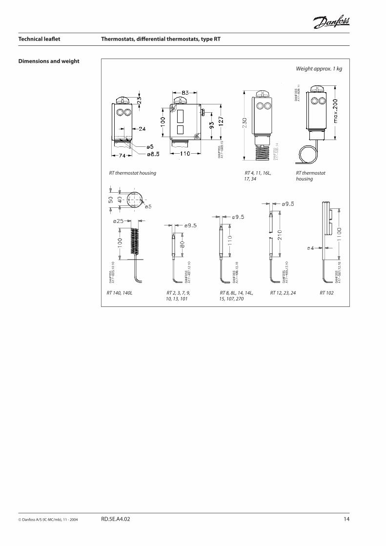
RT 140, 140L RT 2, 3, 7, 9, RT 8, 8L, 14, 14L, RT 12, 23, 24 RT 102 10, 13, 101 15, 107, 270
Dimensions and weightWeight approx. 1 kg
RT thermostat housing RT 4, 11, 16L, RT thermostat 17, 34 housing

Technical leafl et Thermostats, diff erential thermostats, type RT
© Danfoss A/S (IC-MC/mb), 11 - 2004 RD.5E.A4.02 15

Technical leafl et Thermostats, diff erential thermostats, type RT
© Danfoss A/S (IC-MC/mb), 11 - 2004 RD.5E.A4.02 16