Embed Size (px)
Citation preview
FAILURE OF THE NEW ORLEANS 17TH STREET CANAL LEVEE &
FLOODWALL DURING HURRICANE KATRINA
Robert G. Bea, Ph.D, P.E., F. & Life Member, ASCE1
ABSTRACT: Hurricane Katrina resulted in the single most catastrophic failure of a civil engineered system in the history of the United States – failure of the flood defense system for the greater New Orleans area. This paper summarizes results from several forensic studies that have examined the causes for failure of one of the most important components of the flood protection system - failure of the levee and floodwall on the 17th street canal. This failure has been publicly cited as an ‘engineering failure’ (Walsh 2006) that involved ‘unforeseen and unforeseeable’ (Marshall 2006) conditions. This paper illustrates why the engineering failure was firmly rooted in a failure to translate research to practice. Geotechnical engineering aspects of the levee and floodwall failure are developed including description of the soil and geologic conditions, analyses of the loading conditions, and analyses of the soil-structure-loading performance characteristics. In addition, the human and organizational aspects that played key roles in development of this failure are detailed. It is concluded that this was a predictable failure whose causes were embedded in a dysfunctional Technology Delivery System. INTRODUCTION
Hurricane Katrina was a very tough teacher. This severe natural event interacted with a pervasively flawed flood defense system for the Greater New Orleans area and developed into a disaster. This disaster was compounded into a catastrophe by similarly flawed evacuation and recovery systems. The result was approximately 2,000 deaths (immediate, delayed, on-site, off-site) and total costs estimated to approach U.S. $500 billion (direct, indirect, immediate, delayed, on-site, off-site). Currently, there are more than $500 billion in Katrina flood damage claim lawsuits in New Orleans Federal District Court.
1 Department of Civil & Environmental Engineering, University of California Berkeley, Berkeley, CA 94720: [email protected]
1
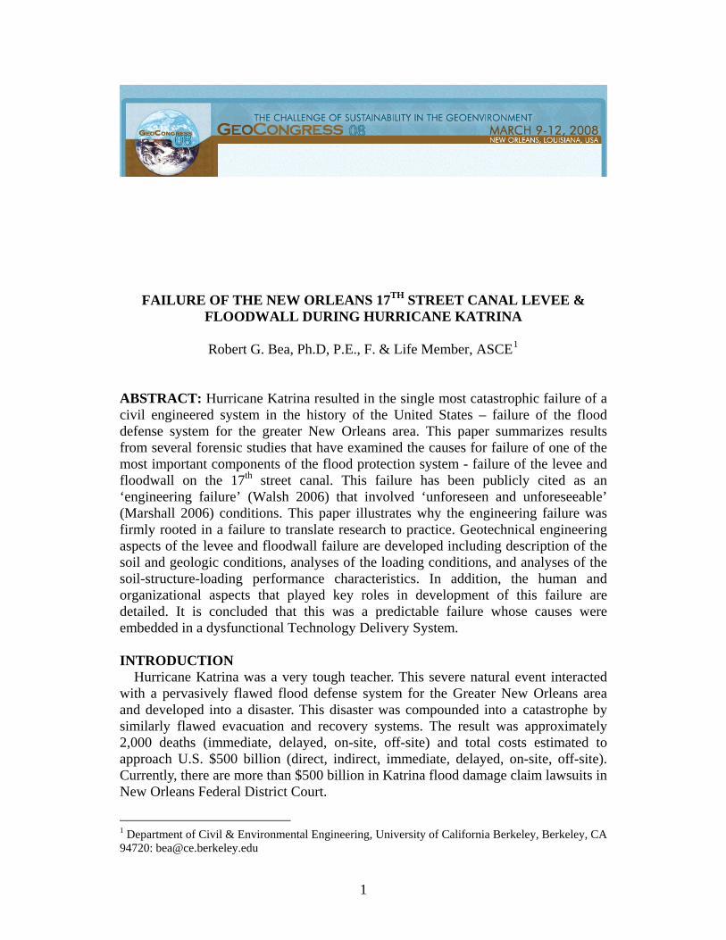
FAILURE AT 17TH STREET CANAL During Hurricane Katrina, a large segment of the levee and floodwall (Fig. 1)
lining the 17th Street canal in New Orleans (Fig. 2) failed catastrophically before the design water elevations (+4.4 m above mean sea level, reference for all vertical elevations) were realized. Eyewitness reports and recorded water levels (Fig. 3) at the drainage pump station located at the head of the 17th Street canal indicated that the failure initiated about 6:00 a.m. on August 29, 2005 when the water level was at about +2 m (USACE IPET 2007).
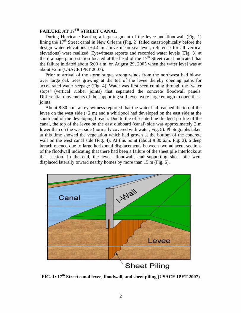
Prior to arrival of the storm surge, strong winds from the northwest had blown over large oak trees growing at the toe of the levee thereby opening paths for accelerated water seepage (Fig. 4). Water was first seen coming through the ‘water stops’ (vertical rubber joints) that separated the concrete floodwall panels. Differential movements of the supporting soil levee were large enough to open these joints.
About 8:30 a.m. an eyewitness reported that the water had reached the top of the levee on the west side (+2 m) and a whirlpool had developed on the east side at the south end of the developing breach. Due to the off-centerline dredged profile of the canal, the top of the levee on the east outboard (canal) side was approximately 2 m lower than on the west side (normally covered with water, Fig. 5). Photographs taken at this time showed the vegetation which had grown at the bottom of the concrete wall on the west canal side (Fig. 4). At this point (about 9:30 a.m. Fig. 3), a deep breach opened due to large horizontal displacements between two adjacent sections of the floodwall indicating that there had been a failure of the sheet pile interlocks at that section. In the end, the levee, floodwall, and supporting sheet pile were displaced laterally toward nearby homes by more than 15 m (Fig. 6).
FIG. 1: 17th Street canal levee, floodwall, and sheet piling (USACE IPET 2007)
2

Lake Pontachatrain
Gulf of Mexico
17th Street canal
FIG. 2: Location of 17th Street canal breach
Mississippi River
Lake Borgne
FIG. 3: Hurricane surge hydrograph showing time history of water levels in the 17th Street Canal (USACE IPET 2007)
3
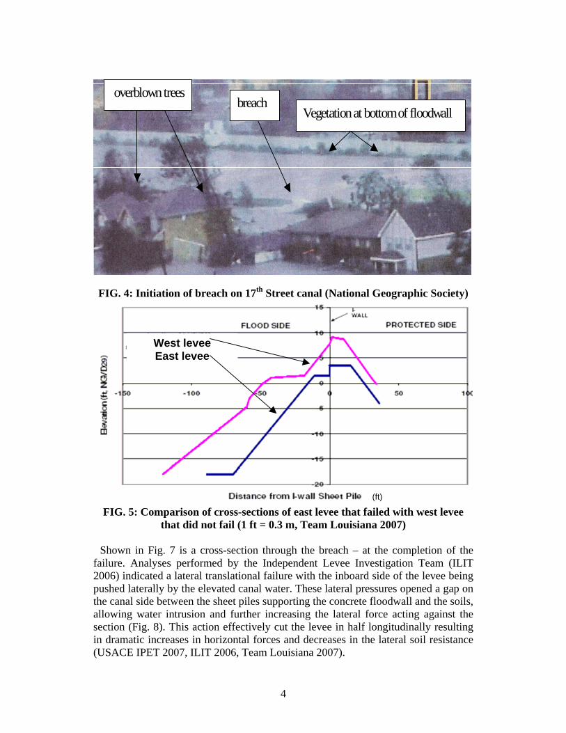
FIG. 4: Initiation of breach on 17th Street canal (National Geographic Society)
breach
overblown trees Vegetation at bottom of floodwall
West levee East levee
FIG. 5: Comparison of cross-sections of east levee that failed with west levee
Shown in Fig. 7 is a cross-section through the breach – at the completion of the
f
(ft)
that did not fail (1 ft = 0.3 m, Team Louisiana 2007)
ailure. Analyses performed by the Independent Levee Investigation Team (ILIT 2006) indicated a lateral translational failure with the inboard side of the levee being pushed laterally by the elevated canal water. These lateral pressures opened a gap on the canal side between the sheet piles supporting the concrete floodwall and the soils, allowing water intrusion and further increasing the lateral force acting against the section (Fig. 8). This action effectively cut the levee in half longitudinally resulting in dramatic increases in horizontal forces and decreases in the lateral soil resistance (USACE IPET 2007, ILIT 2006, Team Louisiana 2007).
4
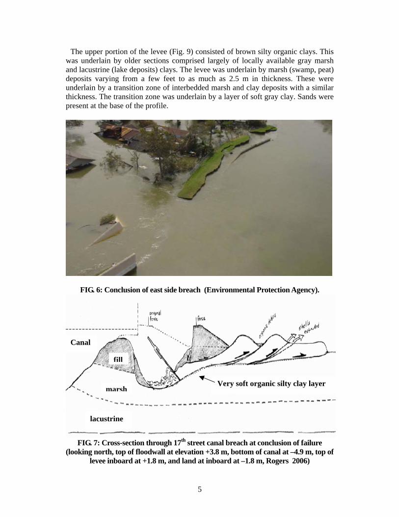
The upper portion of the levee (Fig. 9) consisted of brown silty organic clays. This w
FIG. 6: Conclusion of east side breach (Environmental Protection Agency).
as underlain by older sections comprised largely of locally available gray marsh and lacustrine (lake deposits) clays. The levee was underlain by marsh (swamp, peat) deposits varying from a few feet to as much as 2.5 m in thickness. These were underlain by a transition zone of interbedded marsh and clay deposits with a similar thickness. The transition zone was underlain by a layer of soft gray clay. Sands were present at the base of the profile.
thFIG. 7: Cross-section through 17 street canal breach at conclusion of failure
(looking north, top of floodwall at elevation +3.8 m, bottom of canal at –4.9 m, top of levee inboard at +1.8 m, and land at inboard at –1.8 m, Rogers 2006)
fill
marsh
lacustrine
Very soft organic silty clay layer
Canal
5
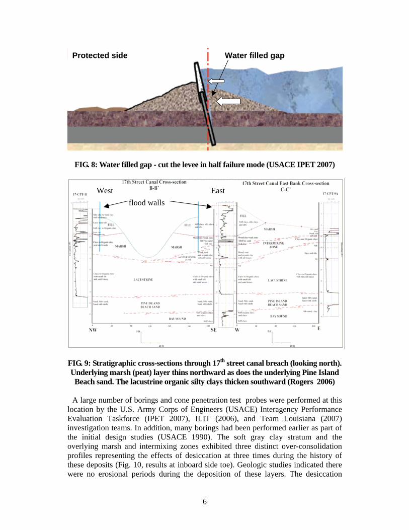
Protected side Water filled gap
FIG. 8: Water filled gap - cut the levee in half failure mode (USACE IPET 2007)
flood walls East West
FIG. 9: Stratigraphic cross-sections through 17th street canal breach (looking north). Underlying marsh (peat) layer thins northward as does the underlying Pine Island Beach sand. The lacustrine organic silty clays thicken southward (Rogers 2006)
lo e Evaluation Taskforce (IPET 2007), ILIT (2006), and Team Louisiana (2007) in
A large number of borings and cone penetration test probes were performed at thiscation by the U.S. Army Corps of Engineers (USACE) Interagency Performanc
vestigation teams. In addition, many borings had been performed earlier as part of the initial design studies (USACE 1990). The soft gray clay stratum and the overlying marsh and intermixing zones exhibited three distinct over-consolidation profiles representing the effects of desiccation at three times during the history of these deposits (Fig. 10, results at inboard side toe). Geologic studies indicated there were no erosional periods during the deposition of these layers. The desiccation
6
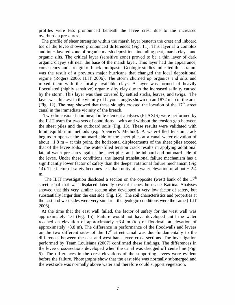
profiles were less pronounced beneath the levee crest due to the increased overburden pressures.
The profile of shear strengths within the marsh layer beneath the crest and inboard toe of the levee showed pronounced differences (Fig. 11). This layer is a complex and inter-layered zone of organic marsh depositions including peat, marsh clays, and o
3). These results were validated with lim
ed that this very similar section also developed a very low factor of safety, but su
an elevation of approximately +3.4 m (top of floodwall at elevation of a
rganic silts. The critical layer (sensitive zone) proved to be a thin layer of dark organic clayey silt near the base of the marsh layer. This layer had the appearance, consistency and strength of black toothpaste. Geologic studies indicated this stratum was the result of a previous major hurricane that changed the local depositional regime (Rogers 2006, ILIT 2006). The storm churned up organics and silts and mixed them with the locally available clays. A layer was formed of heavily flocculated (highly sensitive) organic silty clay due to the increased salinity caused by the storm. This layer was then covered by settled sticks, leaves, and twigs. The layer was thickest in the vicinity of bayou sloughs shown on an 1872 map of the area (Fig. 12). The map showed that these sloughs crossed the location of the 17th street canal in the immediate vicinity of the breach.
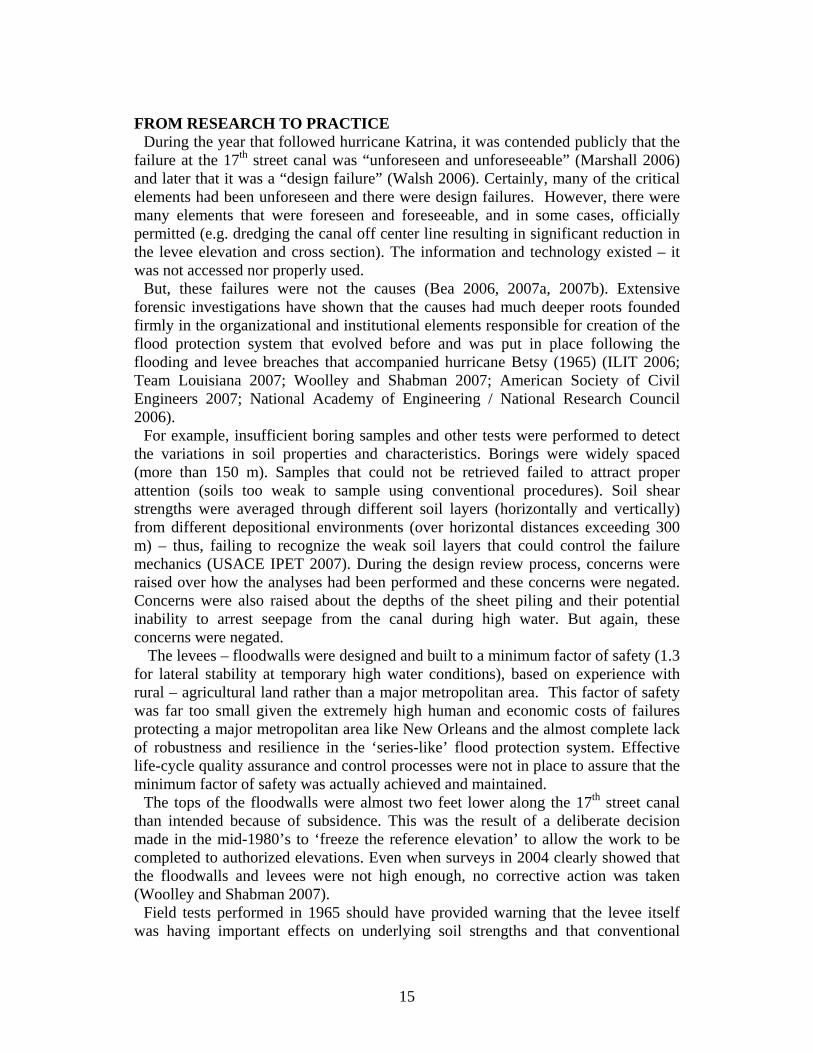
Two-dimensional nonlinear finite element analyses (PLAXIS) were performed by the ILIT team for two sets of conditions – with and without the tension gap between the sheet piles and the outboard soils (Fig. 1
it equilibrium methods (e.g. Spencer’s Method). A water-filled tension crack begins to open at the outboard side of the sheet piles at a canal water elevation of about +1.8 m – at this point, the horizontal displacements of the sheet piles exceed that of the levee soils. The water-filled tension crack results in applying additional lateral water pressures against the sheet piles and the inboard and outboard side of the levee. Under these conditions, the lateral translational failure mechanism has a significantly lower factor of safety than the deeper rotational failure mechanism (Fig 14). The factor of safety becomes less than unity at a water elevation of about + 2.4 m.
The ILIT investigation disclosed a section on the opposite (west) bank of the 17th street canal that was displaced laterally several inches hurricane Katrina. Analyses show
bstantially larger than the east side (Fig. 15). The soil characteristics and properties at the east and west sides were very similar – the geologic conditions were the same (ILIT 2006).
At the time that the east wall failed, the factor of safety for the west wall was approximately 1.6 (Fig. 15). Failure would not have developed until the water reachedpproximately +3.8 m). The difference in performance of the floodwalls and levees
on the two different sides of the 17th street canal was due fundamentally to the differences between the east and west bank levee cross sections. The investigation performed by Team Louisiana (2007) confirmed these findings. The differences in the levee cross-sections developed when the canal was dredged off centerline (Fig. 5). The differences in the crest elevations of the supporting levees were evident before the failure. Photographs show that the east side was normally submerged and the west side was normally above water and therefore could support vegetation.
7
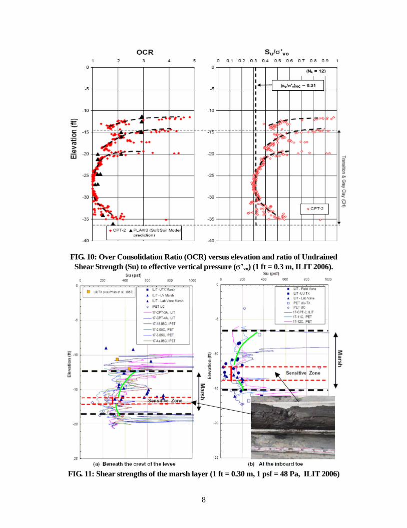
FIG. 10: Over Consolidation Ratio (OCR) versus elevation and ratio of Undrained
Shear Strength (Su) to effective vertical pressure (σ’ ) (1 ft = 0.3 m, ILIT 2006). vo
FIG. 11: Shear strengths of the marsh layer (1 ft = 0.30 m, 1 psf = 48 Pa, ILIT 2006)
8

17th Street canal breach
sloughs with 17th Street canal alignment in vicinity of the 2005 breach (Rogers 2006)
FIG. 12: 1872 Map overlaid with 1936 street map showing intersections of bayou
Canal side Protected side
FIG. 13: Deformed mesh plot at failure from PLAXIS two-dimensional finite element analyses (ILIT 2006)
9
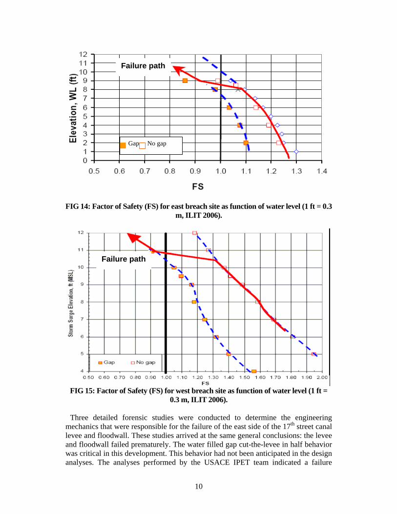
FIG 14: Factor of Safety (FS) for east breach site as function of water level (1 ft = 0.3 m, ILIT 2006).
FIG 15: Factor of Safety (FS) for west br ach site as function of water level (1 ft =
Three detailed forensic studies d to determine the engineering echanics that were responsible for the failure of the east side of the 17th street canal
levee and floodwall. These studies arrived at the same general conclusions: the levee and floodwall failed prematurely. The water filled gap cut-the-levee in half behavior was critical in this development. This behavior had not been anticipated in the design analyses. The analyses performed by the USACE IPET team indicated a failure
e0.3 m, ILIT 2006).
were conducte
m
Gap No gap
Failure path
Failure path
10

mode involving the deeper lascustrine clays. The ILIT team indicated a failure mode involving the shallower marsh intermixed zone that contained the very weak and sensitive organic silty clay layer that was missed in the IPET soil characterizations. The analys Team Louisiana also confirmed these findings.
One of the potentially important issues involved in development of the breach was the subterranean water flow and pressure effects associated with the underlying marsh and transition zone layers overlying the lacustrine clay and beach sand layers found at this site. The USACE IPET studies associated with the centrifuge model testing (Appendix 5 of IPET 2007 report) and the final report (Appendix 17) did specifically address such conditions. These studies were based on soil characterizations in which the tips of the sheet piling penetrated into the lacustrine clay layer effectively cutting off water flow and pressure effects.
In contrast, the ILIT studies were based on soil characterizations in which the tips of the sheet piling did not penetrate into the lacustrine clay layer, but rather penetrated into an overlying intermixing zone that could allow water migration and pressure effects. Water pressure and migration effects were specifically included in the ILIT analyses (Figs. 13,14,15).
w .g. Figs. 9, 10 and 11, ILIT 2006 e in the field during the ILIT soil
es performed by
This important difference was based on the very detailed soil characterization fieldork, geologic studies, and historic mapping studies conducted during the ILIT study
). Observations mad
(eborings performed in this area showed that the buried marsh and transition zone sediments (swamp deposits) had very high horizontal water conductivity (permeability). The field observations indicated that the horizontal conductivity was much higher than the vertical conductivity due to the horizontally layered structure of the organic – marsh materials.
During the ILIT studies, it was not possible to perform in situ tests to determine the hydraulic conductivity characteristics of the buried marsh – transition layers. In the initial set of results, a horizontal hydraulic conductivity (permeability coefficient) of 10-2 cm/sec was used. A value 10 times less was used for the vertical permeability. These results were based on published results for intrinsic – insitu horizontal permeabilities for soils and on results from recent high quality laboratory and field measurements performed on peat – marsh deposits similar to those found at the 17th Street canal location (Beckwith et al 2002, Mesri and Ajlouni 2007). It is important to note that there are potentially very important differences between permeability coefficients determined from conventional laboratory tests and those that are actually present in the field. Permeability coefficients based on results from consolidation tests fail to capture important effects of sampling and anisotropic permeability caused by the structure of the organic materials (Mesri and Ajlouni 2007, Mitchell 1976).
Recently, this same issue developed in evaluations of levee vulnerability in the Sacramento Delta area. This area has geologic depositional and geotechnical characteristics that are very similar to those of the Mississippi River Delta area. In this very extensive study of about 100 failures of levees during flood stages it was concluded: “The Vulnerability team believes 80 percent of the past failures (levees) can be attributed to seepage-induced failures. The team also believes that both through and under seepage-induced failures occurred in equal numbers. The remaining 20% of past failures can be attributed to overtopping” (URS 2007). In their analytical studies of levee vulnerabilities
11

based on results from laboratory testing, field testing, and analyses of previous breaches, horizontal permeabilities in the range of 10-3 to 10-4 cm/sec were used for the organic peat and marsh layers.
Based on all available information on the geologic and geotechnical characteristics of the east side breach area, transient flow analyses were performed (Fig. 16) using GEOSTUDIO SEEP/W (Cobos-Roa and Bea 2007).
SHEET PILE
STORM SURGE AT 5.0ft (MSL)
MARSH
GREY CLAY
SAND
TAN CLAY (FILL)
INTERMIXING ZONE
Distance (ft)0 5 10 15 20 25 30 35 40 45 50 55 60 65 70 75 80 85 90 95 10010511011512012513013514014515015516016
-506-4
-42-38-34-30-26-22-18-14-10-6-226
101418
Elevation (ft)
Fig. 16: Transient flow analyses model geometry (1 foot = 0.30 m)
The water elevation versus time characteristics provided in Fig. 3 were utilized in these analyses. These analyses incorporated a very wide range in horizontal permeabilities (10-2 to 10-6 cm/sec) of the marsh – intermixing zone soils that connect the bottom of the 17th Street canal with the protected landside (note that the bottom of the canal is at an elevation lower than the bottoms of the sheet piling). The transient flow analyses in
he canal increased there were rapid increases in the water pressures in the marsh –intermixing zone soils. The transient pore pressure analyses indicated that in excess of 95% of the steady-state pressures for a water level of rated by 6:00 a.m. on August 29, 2005.
Fig. 18 shows the variation of pore pressure along the bottom of the marsh – intermixing zone layers that underlie the east breach site for a water level of +1.8 m. The pore pressures along the bottom of the marsh – intermixing zone layers vary less than 5% when the in situ horizontal hydraulic conductivity (k) decreases from 10-2 to 10-6 cm/sec. The insensitivity of the pore pressures to the hydraulic conductivity is due to the saturated conditions of the layers – the layers are able to quickly communicate the pressures from the rising water in the canal. There is virtually no obstacle in pressure development underneath the levee toward the landside toe. The sheet piling were not driven deep enough to form an effective barrier to the seepage – water pressure development. Most important, the results indicate that the hydraulic pressures are sufficient at the toe of the levee to exceed the overburden pressures from the soils and hence indicate a very high probability of levee toe ‘blow-out’. It is clearly apparent for a very wide range in
dicated that even for the very lowest horizontal permeability, there was almost direct water pressure communication under and through the levee trough the marsh – intermixing zone soils (Fig. 17). As the water level in t
+2 m were gene
12

plausible in situ horizontal permeabilities that the marsh – intermixing zone water conduct
ivity is a key player in the hydraulic behavior and stability at this location.
750
1000
1250
1500Pr
essu
re (p
sf)
8/28/05 21:00 (0hrs) 8/28/05 22:00 (1hrs) 8/28/05 23:00 (2hrs) 8/29/05 0:00 (3hrs)8/29/05 1:00 (4hrs) 8/29/05 2:00 (5hrs) 8/29/05 3:00 (6hrs) 8/29/05 4:00 (7hrs)8/29/05 5:00 (8hrs) 8/29/05 6:00 (9hrs) Steady State 7ft
0
250
500
80 90 100 110 120 130 140
Distance (ft) FIG. 17: Pore water pressure development along bottom of marsh deposit
(horizontal permeability of 10-6 cm/sec).
1400
1600
k= 1e-06 cm/s k= 1e-05 cm/s k= 1e-04 cm/s k= 1e-03 cm/s k= 1e-02 cm/s
400
600
800
1000
1200
80 90 100 110 120 130 140 150 160 170 180
Distance
Pres
sure
(psf
)
(Ft)
FIG. 18: Pore water pressures along bottom of marsh – transition zone layers
for SSC water level elevation of + 1.8 m
Toe of levee position Canal side
Sheet pile position
Sheet pile position
Canal side
Toe of levee position
13

14
Transient and steady-state pore pressure development analyses also were performed for
the ‘blown-over tree root-ball’ at the toe of the levee condition (4.6 m diameter, 1.5 m thick). To model this condition, elements were removed in three stages starting at 5:00 a.m. (to simulate the tree being blown over) from the finite elements and new boundary conditions assigned to the appropriate nodes. Results for the entire range of permeabilities showed increasing hydraulic gradients as the hole got deeper and wider and as the storm surge increased in elevation. For a surge elevation of +6 feet, vertical hydraulic gradients larger than unity were found in the marsh deposit and in the underlying intermixing deposit in the vicinity of the toe of the levee and root-ball removal zone (Fig. 19). Such vertical hydraulic gradients would have led to additional softening and/or erosion of the marsh – inte ls leading to a ‘blow-out’ at this location. These analyses corroborated the observations made in the field during and after the failure concerning the high likelihood that the overblown trees played instrumental roles in triggering the failure and in defining the location of initiation of the failure on the east s
rmixing zone soi
ide of the canal.
Distance (ft)0 5 10 15 20 25 30 35 40 45 50 55 60 65 70 75 80 85 90 95 100105110115120125130135140145150155160165170
()
-50
-46
-42
-38
-34
-30
-26
-22
-18
-14
-10
-6
-2
2
6
10
14
18
9: Tree removal simulation (final stage) vertical hydraulic gradients for
surge at +1.8 m (1 foot = 0.3 m)
The finite element analytical models showed vertical hydraulic gradients that exceed unity in the immediate vicinity of the toe of the protected side levee. Interestingly, they are the highest for the in situ horizontal permeabilities for the marsh and intermixing zone in the range of 10-6 cm/sec. The marsh and intermixing zone become an effective blanket th lg blowout failures. The ic, geotechnical and m
FIG: 1
at acts to develop very high pore water pressure gradients leading to uplift and verticaradients that cause reductions in levee – flood wall – sheet piling lateral resistance and/or
combination of the geometric, hydro-geolog
echanical aspects of this location combine to generate a very important weak zone that very likely led to the initiation of the failure that developed into the catastrophic east side breach.
1.5 (Surface) 0.3 (Sensitive Layer)
Elevation (ft)
Land side
Canal side
Root ball hole
FROM RESEARCH TO PRACTICE
During the year that followed hurricane Katrina, it was contended publicly that the failure at the 17th street canal was “unforeseen and unforeseeable” (Marshall 2006) and later that it was a “design failure” (Walsh 2006). Certainly, many of the critical elements had been unforeseen and there were design failures. However, there were many elements that were foreseen and foreseeable, and in some cases, officially permitted (e.g. dredging the canal off center line resulting in significant reduction in the levee elevation and cross section). The information and technology existed – it was not accessed nor properly used.
But, these failures were not the causes (Bea 2006, 2007a, 2007b). Extensive forensic investigations have shown that the causes had much deeper roots founded firmly in the organizational and institutional elements responsible for creation of the flood protection system that evolved before and was put in place following the flooding and levee breaches that accompanied hurricane Betsy (1965) (ILIT 2006; Team Louisiana 2007; Woolley and Shabman 2007; American Society of Civil Engineers 2007; National Academy of Engineering / National Research Council 2006).
For example, insufficient boring samples and other tests were performed to detect the variations in soil properties and characteristics. Borings were widely spaced (more mples that could not be retrieved failed to attract proper attention (soils too weak to sample using conventional procedures). Soil shear strengths were averaged through different soil layers (horizontally and vertically) from different depositional environments (over horizontal distances exceeding 300 m) – thus, failing to recognize the weak soil layers that could control the failure mechanics (USACE IPET 2007). During the design review process, concerns were raised over how the analyses had been performed and these concerns were negated. Concerns were also raised about the depths of the sheet piling and their potential inability to arrest seepage from the canal during high water. But again, these concerns were negated.
The levees – floodwalls were designed and built to a minimum factor of safety (1.3f rural – agricultural land r ea. This factor of safety
as far too small given the extremely high human and economic costs of failures pr
y and Shabman 2007). Field tests performed in 1965 should have provided warning that the levee itself
lying soil strengths and that conventional
than 150 m). Sa
or lateral stability at temporary high water conditions), based on experience with
ather than a major metropolitan arw
otecting a major metropolitan area like New Orleans and the almost complete lack of robustness and resilience in the ‘series-like’ flood protection system. Effective life-cycle quality assurance and control processes were not in place to assure that the minimum factor of safety was actually achieved and maintained.
The tops of the floodwalls were almost two feet lower along the 17th street canal than intended because of subsidence. This was the result of a deliberate decision made in the mid-1980’s to ‘freeze the reference elevation’ to allow the work to be completed to authorized elevations. Even when surveys in 2004 clearly showed that the floodwalls and levees were not high enough, no corrective action was taken (Woolle
was having important effects on under
15
laboratory tests combined with conventional stability analysis methods would tend to over-predict the factors of safety. Borings taken at the crests of the levees in New Orleans were taken to be representative of the soil strength at and beyond the toes of the levees. The method of planes was applied in a prescribed manner that did not allow analyses of the critical modes of failure.
In 1964 - 1965 the USACE ran a full scale levee test in the Atachafalaya basin in which advanced studies were conducted regarding characterizations of the soil s
he importance of local soil conditions to the performance of the levee was c
aracterization of the soil properties was required.” Further th
flection resulted in s
trengths and performance and stability characteristics of the levee (USACE 1968; Kaufman and Weaver 1967). The levee test sections were thoroughly instrumented and their performance monitored during and after construction. Various analytical methods were used to evaluate the usefulness and reliability of the various methods. These developments clearly indicated the need to understand the geologic soil depositional processes and the associated variations in soil strengths (horizontal and vertical) in order to understand the performance and stability characteristics of levees. Tlearly pointed out. Additional reports and professional papers were published that
resulted in significant advances to the engineering knowledge (Duncan 1970, Ladd et al. 1972; Edgers et al. 1973; Foott and Ladd 1973, 1977).
Even earlier, geologic studies performed by the USACE indicated the treacherous nature of the soil conditions and the need to be on high alert for zones of unusually low soil strength and very high permeability. In-depth background on the geologic and depositional environment of vital importance to understanding the characteristics of the Mississippi Basin soils were developed in the 1950s and 1960s (Kolb and Van Lopek 1958; Krinitzsky and Smith 1969). The USACE lead in development of this background. Of particular importance was recognition that the marsh and swamp deposits were “treacherous” and highly variable. It was repeatedly pointed out that “careful and detailed ch
e studies that the method based on traditional USACE soil characterization and stability analyses gave factors of safety that were too large (Foott and Ladd 1977). As in the first instance, these developments were not reflected in the design guidelines and practices that were used.
Full scale floodwall loading tests performed in 1985 should have warned the engineers that the sheet pile – soil interactions could result in the ‘cut the levee in half’ failure mode. The failure mode involved lateral deflection of the concrete floodwall and the sheet piles that supported that floodwall. This deeparation between the stiff supporting sheet piling and the soft soil of the levee on
the water side of the wall. Water was then able to enter the gap and exert additional lateral forces on the remaining half of the levee-floodwall. Now, the levee only had about half of its width able to transmit the lateral forces to the underlying soils. This combination resulted in lowering the lateral resistance with a commensurate lowering of the factor of safety.
In 1985, the New Orleans District of the USACE conducted a full scale instrumented lateral load test of a 200-foot long sheet pile flood wall in the Atachafalaya basin (USACE 1988a). This particular location (south of Morgan City, Louisiana) was chosen because of the close correlation of the soil conditions in the New Orleans area with those at the test location. “The foundation soils are relatively
16
poor, consisting of soft, highly plastic clays, and would be representative of near worst case conditions in the NOD (New Orleans District).”
ete wall - sheet pile joint and in the sheet p
n mode much earlier) provided critical flaws. The d
Test data (from slope indicators) from the highly instrumented sheet pile wall and adjacent supporting soils indicated a gap behavior (separation of the sheet piles from the soils). The test was designed to take a 2.4 m height of water (above the supporting ground level) with a factor of safety of 1.25. But the wall was already in a failure condition (rapidly increasing lateral displacements with no increase in loading) when the water level reached 2.4 m instead of the calculated 3.1 m. Strain gage readings on the sheet piles indicated that they were well below the steel yield point, thus the yielding had to have been developing in the supporting soils. Two very important pieces of information developed by the E-99 sheet pile tests were that there was potential soil separation from the sheet piles (allowing water to penetrate below the ground surface between the piles and the soils) and that the calculated safety factor was not reached (it was over-estimated due to unanticipated deformations in the soils).
Additional reports and professional papers further developed the experimental information. Advanced analytical models were developed that could be used to help capture the observed behavior (USACE Waterways Experiment Station 1989). Later developments in this work were reported by Oner, Dawkins and Mosher (1997): “As the water level rises, the increased loading may produce separation of the soil from the pile on the flooded side (i.e., a “tension crack” develops behind the wall). Intrusion of free water into the tension crack produces additional hydrostatic pressures on the wall side of the crack and equal and opposite pressures on the soil side of the crack. Thus part of the loading is a function of system deformations.”
These developments in technology were not reflected in the design guidelines used (USACE 1988b, 1989, 1990). A traditional method of active and passive pressures acting along the length of the sheet piles embedded in the earth levee was used to determine stresses induced in the concr
iles. It was assumed that the soils in the supporting levee were not deforming under the varying water levels. This traditional method did not incorporate the information developed from the E99 floodwall test. The traditional design guideline-based method used to design and engineer the floodwall system did not possess the required attributes of validity and reliability (Kardon, Bea, Williamson 2006).
The long-term deficiencies in translating research to practice were combined with flaws incorporated during the operating and maintenance phases. The decision to permit the off-centerline dredging that resulted in the significant decrease in the outboard side levee elevation and cross section on the east side (rising water could initiate the prying water intrusio
ecisions to allow large trees to grow at the toes of the levees proved to provide additional important flaws and defects. Although the records reflect that inspections were conducted and the levees received acceptable ratings, the records appear to be incomplete or inaccurate. In the end, given this combination of critical flaws and defects, when the system was tested, it failed at a water level far below that intended.
17
CONCLUSIONS Failure of the levee and floodwall at the 17th street canal provides an excellent
example of how research was not effectively translated to practice in geotechnical engineering. Geotechnical engineering technology is very able to demonstrate why this catastrophic failure developed. This technology existed at the time this failure was incubated and developed. As one investigator insightfully observed: “we failed to connect the dots.” The geotechnical engineering contributions to this failure were not causes – they were results of multiple breakdowns in the Technology Delivery System that developed over a 40-year period (Bea 2007a, 2007b; ILIT 2006). The challenge of the future is to learn the painful lessons from this disaster so that they will not be repeated.
A
oa, X
OMAE 2007-29649, 1-10, ASME, New York. Beckwith, C.W., Baird, A. J., and Heathwaite, A. L. (2002). “Anistotropy and depth-
related heterogeneity of hydraulic conductivity in a bog peat. I: laboratory measurements,” Hydrological Processes, 17, 89-101.
CKNOWLEDGEMENTS John Schmertmann provided the fundamental knowledge of geotechnical
engineering that was critically important to development of my understanding of the engineering mechanics of this failure. I owe a large measure of the success of my career to the gifts John gave me.
This paper could not have been written without the leadership, knowledge, and professionalism of Drs. Raymond Seed and David Rogers. Ray and Dave provided the important insights into the engineering mechanics of this failure. University of California Berkeley geotechnical engineering graduate students Diego Cabos-R
avier Vera-Grunauer and Adda Athanasopoulos provided vital field, laboratory and analytical support for the work summarized in this paper. The GEO Institute manuscript reviewers are also due recognition for their constructive detailed suggestions; these suggestions had major effects on the contents of this paper. Because of these people and the other members of the ILIT team, failure to deeply understand the lessons of this disaster – to see through the fog of this failure - was not an option.
REFERENCES
ASCE External Review Panel (2007). The New Orleans Hurricane Protection System: What Went Wrong and Why. ASCE, Reston, VA. www.pubs.asce.org.
Bea, R.G. (2006). “Reliability and Human Factors in Geotechnical Engineering.” ASCE J. Geotechnical and Geoenvironmental Engineering, 132 (5), 631-643.
Bea, R.G. (2007a). “Reliability Assessment & Management Lessons from Hurricane Katrina,” Proceedings 6th International Conference on Offshore Mechanics and Arctic Engineering, OMAE 2007-29650, 1-12, ASME, New York.
Bea, R.G. (2007b). “Lessons from Failure of the Flood Protection System for the Greater New Orleans Area During Hurricane Katrina,” Proceedings 6th International Conference on Offshore Mechanics and Arctic Engineering,
18
Cobos-Roa, D. and Bea, R. G. (2007). Parametric Analyses for the Breach on the
n. Research report R73-27, Dept. of Civil Engineering, Massachusetts Institute of Technology, Cambridge MA.
7). “Behaviour of Atchafalaya levees during
esearch in the Interest of Society Report, Berkeley,
17th Street Canal During Hurricane Katrina, New Orleans, LA. Report to Risk Assessment and Management Services, Moraga, CA, September 30.
Duncan, J.M. (1970). Strength and stress-strain behavior of Atchafalaya foundation soils. Research Report TE70-1, Department of Civil Engineering, University of California, Berkeley.
Edgers, L. et al (1973). Undrained creep of Atchafalaya levee foundation clays. Research Report R73-16, Soils Publication No. 319, Dept. of Civil engineering, Massachusetts Institute of Technology, Cambridge MA.
Foott, R., and Ladd, C. C. (1973). The behavior of Atchafalaya test embankments during constructio
Foott, R., and Ladd, C. C. (197construction.” Geotechnique, 27(2), 137-160.
ILIT (2006). Investigation of the Performance of the New Orleans Levee Systems in Hurricane Katrina on August 29, 2005, National Science Foundation and Center for Information Technology RCA, www.risk.berkeley.edu.
Kardon, J.B., Bea, R.G., Williamson, R.B. (2006). “Validity and Reliability of Forensic Engineering Methods and Processes.” Proceedings 4th Forensic Congress, ASCE, 1-11.
Kaufman, R. I., and Weaver, F. J. (1967). “Stability of Atchafalaya levees.” ASCE J. Soil Mechanics and Foundations Division, 93(4), 157-176.
Kolb, C.R., and Van Lopik, J.R. (1958). Geology of the Mississippi River Deltaic Plain, Southern Louisiana. Technical Report No. 3-483, U.S. Army Engineer Waterways Experiment Station, Vicksburg, MS.
Krinitzsky, E. L., and Smith, F. L (1969). Geology of backswamp deposits in the Atchafalaya basin, Louisiana. Technical Report S-69-8, U.S. Army Engineer Waterways Experiment Station, Vicksburg, MS.
1972). Engineering properties of soft foundation clays at two
Mit
ricane
Ladd, C. C. et al. (south Louisiana levee sites. Research Report R72-26, Dept. of Civil Engineering, Massachusetts Institute of Technology, Cambridge MA. rshall, B. (2006). “Report: Levee failure could not be foreseen,” The Times MaPicayune, quotation attributed to Dr. Ed Link, March 11. rri, G. and Ajlouni, M. (2007). “Engineering Properties of Fibrous Peats,” ASCMe E J. Geotechnical and Geoenvironmental Engineering, 177, 7, 850-866. chell, J.K. (1976). Fundamentals of Soil Behavior, John Wiley & Sons, New York.
National Academy of Engineering / National Research Council (2006). First, Second, and Third Report of the Committee on New Orleans Regional HurProtection Projects, The National Academies Press, Washington DC.
er, et al (1997). “Soil-Structure Interaction EffecOn ts in Floodwalls.” Electronic Journal of Geotechnical Engineering, <http://www.ejge.com/1997> (Jan,1, 2006).
19
Rogers, J.D. (2006). “Engineering Geologic Characterization of Levee Failures in New Orleans During Hurricane Katrina,” Proceedings 2006 Annual Meeting Association of Envioronmental and Engineering Geologists, Boston, MA.
on Rouge LA. lity,
a. o.
S. US n Procedure for Sheet-
14,
USn Floodway, Louisiana. Interim Rpt,. New
Wa e, t. General Carl Strock, April 6.
ft Final Report for
Team Louisiana (2007). The Failure of the New Orleans Levee System During Hurricane Katrina and the Pathway Forwards, Louisiana State University Hurricane Center, Bat
URS Corporation / Jack R. Benjamin & Associates, Inc. (2007). Levee VulnerabiTechnical Memorandum, Delta Risk Management Strategy (DRMS) Phase 1, Report to Department of Water Resources, Sacramento C
USACE (1988a). E-99 Sheet Pile Wall Field Load Test Report. Technical Report N1, U.S. Army Engineer Division, Lower Mississippi Valley, Vicksburg, MACE (1989). Development of Finite-Element-Based DesigPile Wall. USACE Waterways Experiment Station, Tech. Report GL-89-Vicksburg, MS.
USACE IPET (2007). Performance Evaluation of the New Orleans and Southeast Louisiana Hurricane Protection System, Final Report, Washington, DC. ACE, New Orleans District (1968). Field tests of levee construction, test sections I, II, and III, Atchafalaya BasiOrleans, LA. lsh, B (2006). “Corps chief admits to ‘design failure’”, The Times-Picayunquotation attributed to L
Woolley, D. and Shabman, L. (2007). Decision-Making Chronology for the Lake Pontchartrain & Vicinity Hurricane Protection Project. Drathe Headquarters, USACE, Institute for Water Resources of the USACE, June.
20