Embed Size (px)
Citation preview

Navy Experimental Diving Unit 321 Bullfinch Road Panama City, FL 32407-7015
TA 08-20 NEDU TR 10-09 SEP 2010
Thalmann Algorithm Decompression Table Generation Software Design Document
Navy Experimental Diving Unit
Author: Distribution Statement A: WAYNE A. GERTH, PH.D. Approved for public release;
distribution is unlimited.
UNCLASSIFIED SECURITY CLASSIFICATION OF THIS PAGE
REPORT DOCUMENTATION PAGE
1a. REPORT SECURITY CLASSIFICATION Unclassified
1b. RESTRICTIVE MARKINGS
2a. SECURITY CLASSIFICATION AUTHORITY
3. DISTRIBUTION/AVAILABILITY OF REPORT DISTRIBUTION STATEMENT A: Approved for public release; distribution is
unlimited.
2b. DECLASSIFICATION/DOWNGRADING AUTHORITY
4. PERFORMING ORGANIZATION REPORT NUMBER(S) NEDU Technical Report No. 10-09
5. MONITORING ORGANIZATION REPORT NUMBER(S)
6a. NAME OF PERFORMING ORGANIZATION Navy Experimental Diving Unit
6b. OFFICE SYMBOL (If Applicable) O2
7a. NAME OF MONITORING ORGANIZATION
6c. ADDRESS (City, State, and ZIP Code) 321 Bullfinch Road, Panama City, FL 32407-7015
7b. ADDRESS (City, State, and Zip Code)
8a. NAME OF FUNDING SPONSORING ORGANIZATION Naval Sea Systems Command
8b. OFFICE SYMBOL (If Applicable) 00C
9. PROCUREMENT INSTRUMENT IDENTIFICATION NUMBER
8c. ADDRESS (City, State, and ZIP Code) 1333 Isaac Hull Avenue, SE Washington Navy Yard, DC 20376
10. SOURCE OF FUNDING NUMBERS
PROGRAM ELEMENT NO.
PROJECT NO.
.
TASK NO.
08-20
WORK UNIT ACCESSION NO..
11. TITLE (Include Security Classification) (U) THALMANN ALGORITHM DECOMPRESSION TABLE GENERATION SOFTWARE DESIGN DOCUMENT
12. PERSONAL AUTHOR(S) Wayne A. Gerth, Ph.D.
13a. TYPE OF REPORT Technical Report
13b. TIME COVERED FROM Oct 2008 TO Sep 2010
14. DATE OF REPORT (Month, Year) Sep 2010
15. PAGE COUNT 82
16. SUPPLEMENTARY NOTATION
17. COSATI CODES 18. SUBJECT TERMS Decompression, air, in-water oxygen, surface decompression using oxygen,
Thalmann Algorithm, VVal-18, VVal-18M, probabilistic models, decompression sickness risk
FIELD GROUP SUB-GROUP
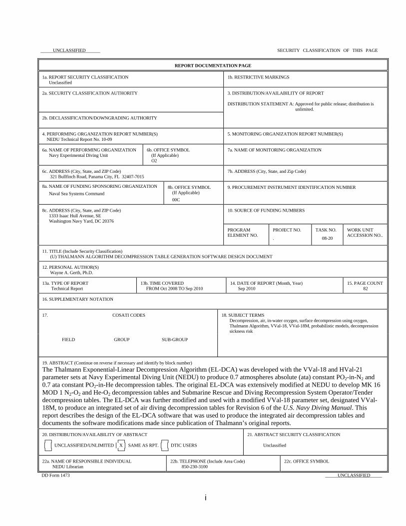
19. ABSTRACT (Continue on reverse if necessary and identify by block number) The Thalmann Exponential-Linear Decompression Algorithm (EL-DCA) was developed with the VVal-18 and HVal-21 parameter sets at Navy Experimental Diving Unit (NEDU) to produce 0.7 atmospheres absolute (ata) constant PO2-in-N2 and 0.7 ata constant PO2-in-He decompression tables. The original EL-DCA was extensively modified at NEDU to develop MK 16 MOD 1 N2-O2 and He-O2 decompression tables and Submarine Rescue and Diving Recompression System Operator/Tender decompression tables. The EL-DCA was further modified and used with a modified VVal-18 parameter set, designated VVal-18M, to produce an integrated set of air diving decompression tables for Revision 6 of the U.S. Navy Diving Manual. This report describes the design of the EL-DCA software that was used to produce the integrated air decompression tables and documents the software modifications made since publication of Thalmann’s original reports.
20. DISTRIBUTION/AVAILABILITY OF ABSTRACT ┌─┐ ┌─┐ ┌─┐ │ │ UNCLASSIFIED/UNLIMITED │ X │ SAME AS RPT. │ │ DTIC USERS └─┘ └─┘ └─┘
21. ABSTRACT SECURITY CLASSIFICATION Unclassified
22a. NAME OF RESPONSIBLE INDIVIDUAL NEDU Librarian
22b. TELEPHONE (Include Area Code) 850-230-3100
22c. OFFICE SYMBOL
DD Form 1473 UNCLASSIFIED
i

ACKNOWLEDGEMENTS The author is grateful to Mr. Denis Thomas for editorial assistance.
ii
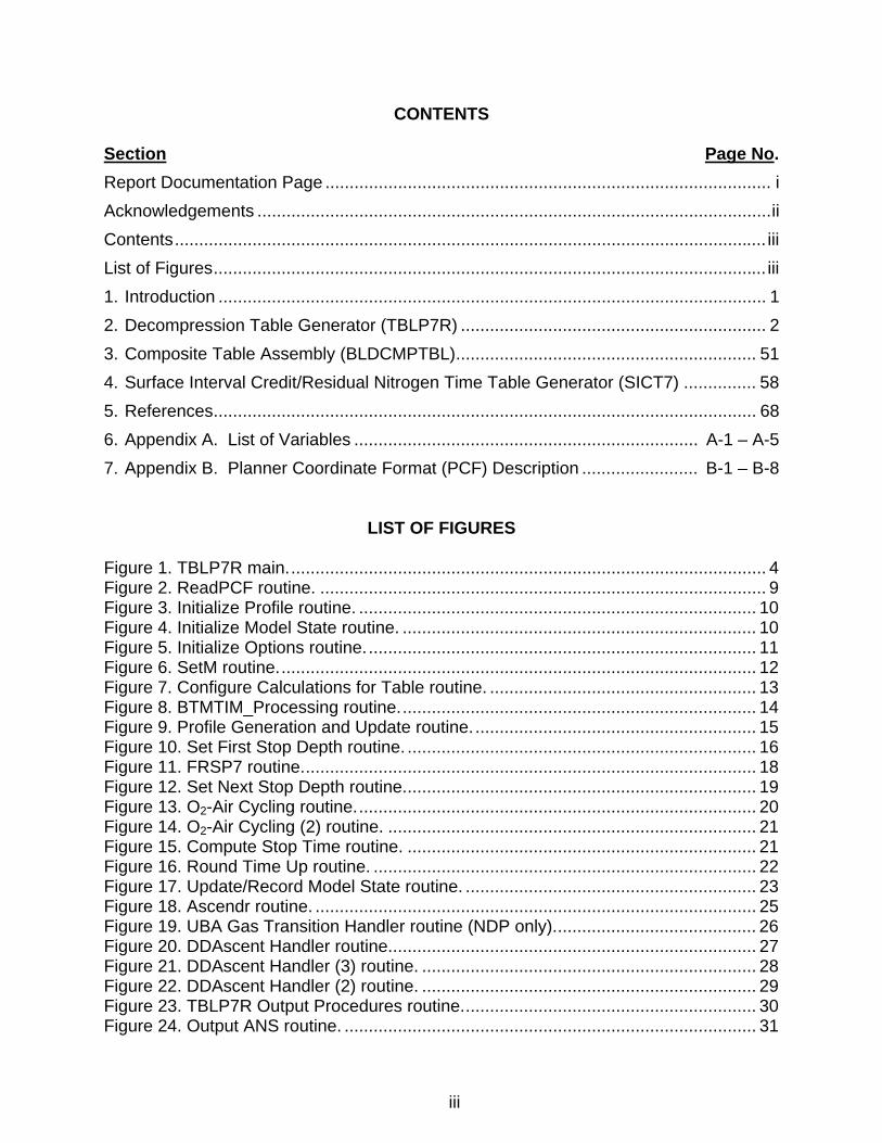
CONTENTS
Section Page No. Report Documentation Page ............................................................................................ i Acknowledgements .......................................................................................................... ii Contents .......................................................................................................................... iii List of Figures .................................................................................................................. iii 1. Introduction ................................................................................................................. 1
2. Decompression Table Generator (TBLP7R) ............................................................... 2
3. Composite Table Assembly (BLDCMPTBL) .............................................................. 51
4. Surface Interval Credit/Residual Nitrogen Time Table Generator (SICT7) ............... 58
5. References ................................................................................................................ 68
6. Appendix A. List of Variables ....................................................................... A-1 – A-5
7. Appendix B. Planner Coordinate Format (PCF) Description ........................ B-1 – B-8
LIST OF FIGURES Figure 1. TBLP7R main. .................................................................................................. 4 Figure 2. ReadPCF routine. ............................................................................................ 9 Figure 3. Initialize Profile routine. .................................................................................. 10 Figure 4. Initialize Model State routine. ......................................................................... 10 Figure 5. Initialize Options routine. ................................................................................ 11 Figure 6. SetM routine. .................................................................................................. 12 Figure 7. Configure Calculations for Table routine. ....................................................... 13 Figure 8. BTMTIM_Processing routine. ......................................................................... 14 Figure 9. Profile Generation and Update routine. .......................................................... 15 Figure 10. Set First Stop Depth routine. ........................................................................ 16 Figure 11. FRSP7 routine. ............................................................................................. 18 Figure 12. Set Next Stop Depth routine. ........................................................................ 19 Figure 13. O2-Air Cycling routine. .................................................................................. 20 Figure 14. O2-Air Cycling (2) routine. ............................................................................ 21 Figure 15. Compute Stop Time routine. ........................................................................ 21 Figure 16. Round Time Up routine. ............................................................................... 22 Figure 17. Update/Record Model State routine. ............................................................ 23 Figure 18. Ascendr routine. ........................................................................................... 25 Figure 19. UBA Gas Transition Handler routine (NDP only). ......................................... 26 Figure 20. DDAscent Handler routine. ........................................................................... 27 Figure 21. DDAscent Handler (3) routine. ..................................................................... 28 Figure 22. DDAscent Handler (2) routine. ..................................................................... 29 Figure 23. TBLP7R Output Procedures routine. ............................................................ 30 Figure 24. Output ANS routine. ..................................................................................... 31
iii
iv
Figure 25. Configure ANS Data routine. ........................................................................ 32 Figure 26. Set Initial ANS_SatGas routine. ................................................................... 33 Figure 27. NLIM7 routine. .............................................................................................. 34 Figure 28. STIM7 routine. .............................................................................................. 36 Figure 29. Stop Time Optimization routine. ................................................................... 37 Figure 30. UPDT7 routine. ............................................................................................ 39 Figure 31. UPDT7 Initialize routine................................................................................ 40 Figure 32. Set Time Constants routine. ......................................................................... 41 Figure 33. Exponential-Linear Crossover Time Computation routine. ........................... 42 Figure 34. Linear-Exponential Crossover Time Computation routine. ........................... 43 Figure 35. Linear Update routine. .................................................................................. 44 Figure 36. Exponential Update routine. ......................................................................... 44 Figure 37. Update IAD routine. ...................................................................................... 45 Figure 38. FCNTRLT routine. ........................................................................................ 46 Figure 39. REPET7 routine. .......................................................................................... 48 Figure 40. Compute RGT routine. ................................................................................. 49 Figure 41. Ascnd4RGT routine. ..................................................................................... 50 Figure 42. BLDCMPTBL Main routine. .......................................................................... 52 Figure 43. File Read and Synch routine. ....................................................................... 54 Figure 44. ASSMBL CMPTBL routine. .......................................................................... 55 Figure 45. Gen SurDO2-ANS routine. ........................................................................... 56 Figure 46. Chamber Decompression routine. ................................................................ 57 Figure 47. SICT7 Main routine. ..................................................................................... 59 Figure 48. Generate SICT routine. ................................................................................ 62 Figure 49. SICT Setup routine. ...................................................................................... 63 Figure 50. Generate RNT Table routine. ....................................................................... 64 Figure 51. Compute Row routine. ................................................................................. 66 Figure 52. ReadPCF SICT7 routine. ............................................................................. 67

1. Introduction
The Thalmann Exponential-Linear Decompression Algorithm (EL-DCA) was developed with the VVal-18 and HVal-21 parameter sets at Navy Experimental Diving Unit (NEDU) to produce 0.7 atmospheres absolute (ata) constant PO2-in-N2 and 0.7 ata constant PO2-in-He decompression tables. Thalmann published FORTRAN source code for the initial operating version of the EL-DCA to compute decompression tables in 19831,2 and described the underlying theory in 1984.3 Additional FORTRAN code for the programs and subroutines of the EL-DCA — code required to include surfacing repetitive groups in computed decompression tables and to compute surface/shallow interval credit tables to support repetitive and multilevel diving — was described and published still later.4,5
Thalmann’s original EL-DCA was extensively modified at NEDU to develop MK 16 MOD 1 N2-O2 and He-O2 decompression tables6,7,8 and Submarine Rescue and Diving Recompression System Operator/Tender decompression tables.9 The EL-DCA was further modified and used with a modified VVal-18 parameter set, designated VVal-18M, to produce an integrated set of air diving decompression tables for Revision 6 of the U.S. Navy Diving Manual.10,11 This report describes the design of the EL-DCA software used to produce the integrated air decompression tables and documents the software modifications made since publication of Thalmann’s original reports. Principal functional enhancements to Thalmann’s original EL-DCA include support of the following:
• input of program setup parameters from a user-editable program initialization file,
• last allowed decompression stop depths at integer multiples of the stop depth increment other than one,
• in-water oxygen decompression with user-setable inspired oxygen fraction and automatic insertion of air-breathing breaks (automatic air/O2 cycling),
• inclusion of travel time between decompression stops in tabulated stop times,
• rule-based inclusion/exclusion of surfacing repetitive group designators with tabulated schedules,
• automatic depth-dependent ascent rates,
• calculation of schedules with instantaneous ascent to surface from depths other than the last allowed decompression stop or without instantaneous ascent to surface from any depth,
• use of compartmental saturation/desaturation half-time ratios other than unity only when the inspired oxygen fraction is greater than or equal to a threshold value specified in the program initialization file,
• support for threshold inert gas tension overpressure, PBOVP, different at surface from that at depth,
1
• computation of surface interval credit tables with surfacing letter final repetitive group designators,
• computation of residual nitrogen times for surface interval credit/residual nitrogen time tables, and
• output of all tabulated schedules in Augmented NMRI Standard (ANS) format 12 for processing by probabilistic models of DCS incidence and time of occurrence.
The Thalmann Algorithm decompression table generation software consists of two main programs: a decompression table generator, TBLP7R, and a surface interval credit and residual nitrogen time table generator, SICT7. A third program, BLDCMPTBL, was developed to supplement TBLP7R for production of the Air Decompression Table in Revision 6 of the U.S. Navy Diving Manual. Each of these programs is described in separate sections of this document. The essential features of program design and operation are depicted in information and process flowcharts with only minimal narrative elaboration. These features are discerned by stepping through the flowcharts beginning at the starting termination of the TBLP7R MAIN chart (Figure 1), the BLDCMPTBL MAIN chart (Figure 42), or the SICT7 MAIN chart (Figure 47). Supporting procedures, for which separate flowcharts are given in most cases, are each indicated by a procedure name in a double-sided box: . The flowcharts for these procedures are readily found by reference to the list of figures on pages ii and iii of this document. An annotated list of program variable names is given in Appendix A.
Procedure Name
Many procedures described in this software design document also support operation of the U.S. Navy Thalmann Algorithm Dive Planner (NDP), sometimes with minor modifications. Such modifications are included in the present documentation with an “NDP only” designation as appropriate. In both TBLP7R and SICT7, all internal calculations are completed with pressures in units of feet of seawater (fsw). Surface pressure is 33 fsw (SURFP_FSW = 33) in accord with the value used in Thalmann’s original code. Internal conversions of meters of seawater (msw) to fsw are made with a conversion factor of 1.0/0.3048 = 3.2808 fsw/msw (MSWpFSW = 0.3048), also as used in Thalmann’s original code.a Maximum permissible tissue tensions (MPTTs) in units of fsw for depths in msw in Thalmann’s original VVal18.dat file were also computed with the 3.2808 fsw/msw factor.
2. Decompression Table Generator (TBLP7R)
FORTRAN code for the original version of TBLP7R was published in NEDU TR 1-831 with addition of an erratum shortly thereafter.2 Subroutines to augment this code and a Thalmann’s 3.2808 fsw/msw conversion factor value is based on a seawater density of 1.02 gm/ml, apparently rounded from the value of 1.02480 gm/ml given by the Undersea and Hyperbaric Medical Society for seawater at 4ºC.12 With this latter unrounded value, the conversion factor value is 1.0/0.30632 = 3.26458 fsw/msw. In comparison, surface pressure of 33 fsw is in accord with the value of 33.0060 fsw obtained with the seawater density of 1.02704 gm/ml reportedly used by U.S. submarines.14
2
support computation of surfacing repetitive groups and residual nitrogen times for repetitive diving were described in NEDU TR 9-85,4 with accompanying code in NEDU TM 85-12.5 TBLP7R processes an ASCII input file of instructions for the schedules that are to be included in the product decompression table. This file must be in Planner Coordinate Format (PCF) described in Appendix B. Depending on the content of the PCF input file, TBLP7R produces either a table of decompression schedules or a Sub-NoD table of no-stop limits with corresponding no-stop times required to reach the top of each surfacing repetitive group at each dive depth. To produce a table of decompression schedules, the PCF input file should contain templates for the schedules to be computed arranged in order of increasing bottom time in groups of increasing dive depth. To compute a Sub-NoD table, the PCF input file should contain a template for one dive to each depth that is to be included in the table. Each of these templates should then prescribe the compression to bottom depth with a dummy bottom time at that depth and the “SD” option after specification of the gas to be breathed at that depth. TBLP7R operation starts with execution of the procedures illustrated in Figure 1.
3
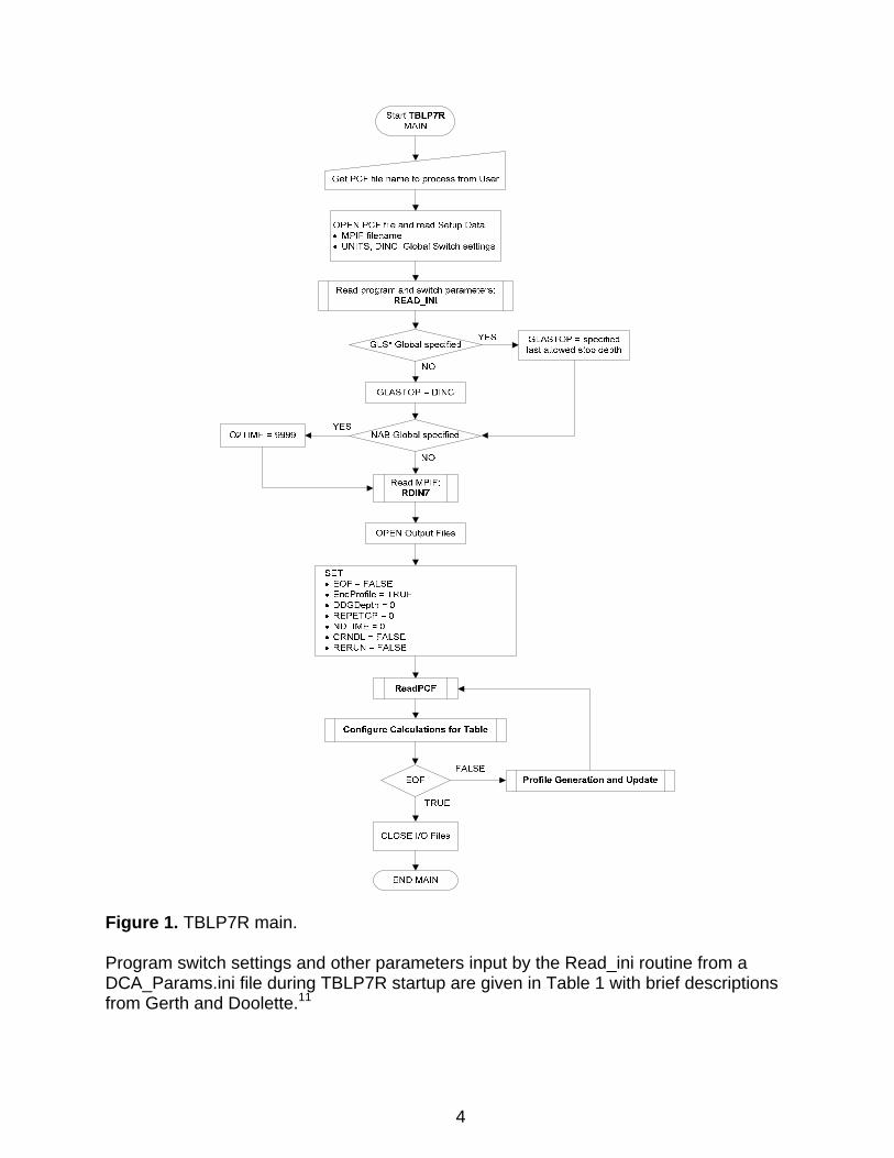
Figure 1. TBLP7R main. Program switch settings and other parameters input by the Read_ini routine from a DCA_Params.ini file during TBLP7R startup are given in Table 1 with brief descriptions from Gerth and Doolette.11
4
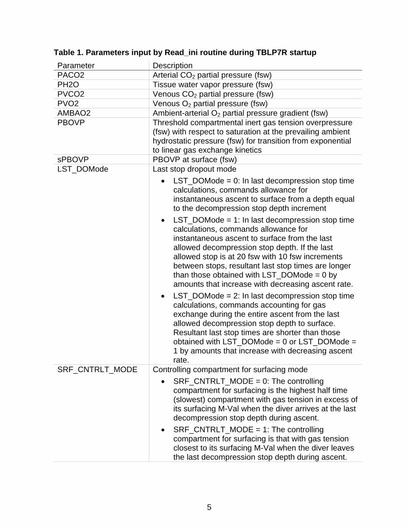
Table 1. Parameters input by Read_ini routine during TBLP7R startup Parameter Description PACO2 Arterial CO2 partial pressure (fsw) PH2O Tissue water vapor pressure (fsw) PVCO2 Venous CO2 partial pressure (fsw) PVO2 Venous O2 partial pressure (fsw) AMBAO2 Ambient-arterial O2 partial pressure gradient (fsw) PBOVP Threshold compartmental inert gas tension overpressure
(fsw) with respect to saturation at the prevailing ambient hydrostatic pressure (fsw) for transition from exponential to linear gas exchange kinetics
sPBOVP PBOVP at surface (fsw) LST_DOMode Last stop dropout mode
• LST_DOMode = 0: In last decompression stop time calculations, commands allowance for instantaneous ascent to surface from a depth equal to the decompression stop depth increment
• LST_DOMode = 1: In last decompression stop time calculations, commands allowance for instantaneous ascent to surface from the last allowed decompression stop depth. If the last allowed stop is at 20 fsw with 10 fsw increments between stops, resultant last stop times are longer than those obtained with LST_DOMode = 0 by amounts that increase with decreasing ascent rate.
• LST_DOMode = 2: In last decompression stop time calculations, commands accounting for gas exchange during the entire ascent from the last allowed decompression stop depth to surface. Resultant last stop times are shorter than those obtained with LST_DOMode = 0 or LST_DOMode = 1 by amounts that increase with decreasing ascent rate.
SRF_CNTRLT_MODE Controlling compartment for surfacing mode • SRF_CNTRLT_MODE = 0: The controlling
compartment for surfacing is the highest half time (slowest) compartment with gas tension in excess of its surfacing M-Val when the diver arrives at the last decompression stop depth during ascent.
• SRF_CNTRLT_MODE = 1: The controlling compartment for surfacing is that with gas tension closest to its surfacing M-Val when the diver leaves the last decompression stop depth during ascent.
5
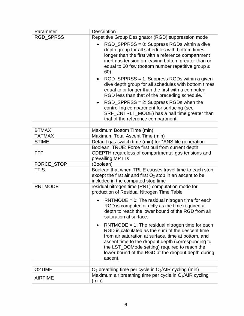
Parameter Description RGD_SPRSS Repetitive Group Designator (RGD) suppression mode
• RGD_SPPRSS = 0: Suppress RGDs within a dive depth group for all schedules with bottom times longer than the first with a reference compartment inert gas tension on leaving bottom greater than or equal to 60 fsw (bottom number repetitive group ≥ 60).
• RGD_SPPRSS = 1: Suppress RGDs within a given dive depth group for all schedules with bottom times equal to or longer than the first with a computed RGD less than that of the preceding schedule.
• RGD_SPPRSS = 2: Suppress RGDs when the controlling compartment for surfacing (see SRF_CNTRLT_MODE) has a half time greater than that of the reference compartment.
BTMAX Maximum Bottom Time (min) TATMAX Maximum Total Ascent Time (min) STIME Default gas switch time (min) for *ANS file generation
FFP Boolean. TRUE: Force first pull from current depth CDEPTH regardless of compartmental gas tensions and prevailing MPTTs
FORCE_STOP (Boolean) TTIS Boolean that when TRUE causes travel time to each stop
except the first air and first O2 stop in an ascent to be included in the computed stop time
RNTMODE residual nitrogen time (RNT) computation mode for production of Residual Nitrogen Time Table
• RNTMODE = 0: The residual nitrogen time for each RGD is computed directly as the time required at depth to reach the lower bound of the RGD from air saturation at surface.
• RNTMODE = 1: The residual nitrogen time for each RGD is calculated as the sum of the descent time from air saturation at surface, time at bottom, and ascent time to the dropout depth (corresponding to the LST_DOMode setting) required to reach the lower bound of the RGD at the dropout depth during ascent.
O2TIME O2 breathing time per cycle in O2/AIR cycling (min)
AIRTIME Maximum air breathing time per cycle in O2/AIR cycling (min)
6
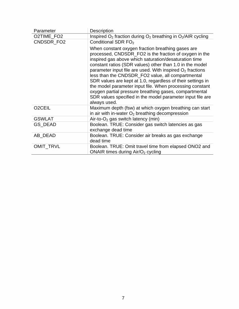
Parameter Description O2TIME_FO2 Inspired O2 fraction during O2 breathing in O2/AIR cycling CNDSDR_FO2 Conditional SDR FO2
When constant oxygen fraction breathing gases are processed, CNDSDR_FO2 is the fraction of oxygen in the inspired gas above which saturation/desaturation time constant ratios (SDR values) other than 1.0 in the model parameter input file are used. With inspired O2 fractions less than the CNDSDR_FO2 value, all compartmental SDR values are kept at 1.0, regardless of their settings in the model parameter input file. When processing constant oxygen partial pressure breathing gases, compartmental SDR values specified in the model parameter input file are always used.
O2CEIL Maximum depth (fsw) at which oxygen breathing can start in air with in-water O2 breathing decompression
GSWLAT Air-to-O2 gas switch latency (min) GS_DEAD Boolean. TRUE: Consider gas switch latencies as gas
exchange dead time AB_DEAD Boolean. TRUE: Consider air breaks as gas exchange
dead time OMIT_TRVL Boolean. TRUE: Omit travel time from elapsed ONO2 and
ONAIR times during Air/O2 cycling
7
After execution of the Read_ini routine, TBLP7R calls the RDIN7 routine to read the maximum permissible tissue tension (MPTT) table from the model parameter input file (*.mpf) specified in the first line of *.pcf input file. The MPTT table comprises a matrix of safe ascent criteria arranged in rows (one for each stop depth) and columns (one for each gas exchange compartment). This convention allows use of tables that may not be built from solutions to simple analytic functions of stop depth and requires an input file with separate matrices of MPTT values for each supported stop depth increment (DINC) in each supported depth unit. The RDIN7 routine opens the specified model parameter input file, then locates and reads the MPTT matrix for the stop depth increment and depth units specified in the *.pcf input file. The dimensions of the MPTT matrix in the *.mpf file define the maximum dive depth (number of rows x DINC) and number of gas exchange compartments (number of columns) that ensuing algorithm operation will support. The RDIN7 routine exits with a FAIL return status, and the start procedure aborts if the specified *.mpf file is not found or the MPTT matrix for the stop depth increment in the specified depth units is not found in the *.mpf file. The program then cycles through processing of each profile in the PCF file under control of the ReadPCF, Configure Calculations for Table, and Profile Generation and Update routines schematized in Figures 2, 7, and 9, respectively.
8

Read TIME at CDEPTH, next FDEPTH, RATE*
Initialize OPTIONS
Read GAS, OPTIONSSet NCODE for ANS GASCODE generation
(OPTIONS override corresponding Global Switches)FN EndProfile = TRUEGTX or TX BTMTIM = TRUE; Bottom time includes descent timeSD SUBNOD = TRUE; Compute row of sub No-D repet group times for CDEPTHND or SD NODLIM = TRUE; Compute No-Stop limit at CDEPTHGDX or DX NODSTP = TRUE; If travel to DEPTH requires ascent then complete no-stopGOD or OD OXYD = TRUE; O2 decompressionGIW or IW IWO2D = TRUE; OXYD = TRUE
STRTO2onTrvl = FALSESTRTSWonTrvl = FALSE
LS LSTOP = TRUE
Initialize PROFILE
Read CDEPTH, next FDEPTH, RATE*, GAS
Read ProfileID.Read & decode GAS data
array
SUCCESS
End of File
Initialize Model State
EndProfile orRERUN
ENTERReadPCF
NO
YESSet EOF = TRUE
Return
Set : DEPTH = FDEPTH
Set : MAXDEPTH = MAX( DEPTH, MAXDEPTH )
NOTE: All READS are from User-specified PCF file.
*NOTE: In TBLP7R, descent and ascent rates are set only once from first values encountered in the first profile processed. This ensures that schedules in the table produced by the program are computed with the same rates.
Set CPO2, GasTsn, and NCODE for specified GAS from stored GAS data
LSTOP
Copy surfacing MVAL row to LASTOP depth row:SETM 1
LASTOP = FDEPTH
NO
YES
Figure 2. ReadPCF routine.
9
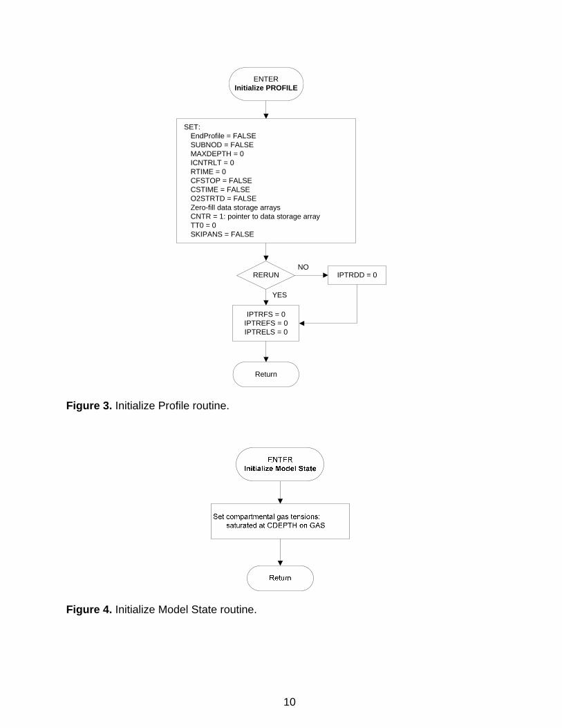
SET:EndProfile = FALSESUBNOD = FALSEMAXDEPTH = 0ICNTRLT = 0RTIME = 0CFSTOP = FALSECSTIME = FALSEO2STRTD = FALSEZero-fill data storage arraysCNTR = 1: pointer to data storage arrayTT0 = 0SKIPANS = FALSE
Return
ENTERInitialize PROFILE
RERUN IPTRDD = 0
IPTRFS = 0IPTREFS = 0IPTRELS = 0
YES
NO
Figure 3. Initialize Profile routine.
Figure 4. Initialize Model State routine.
10
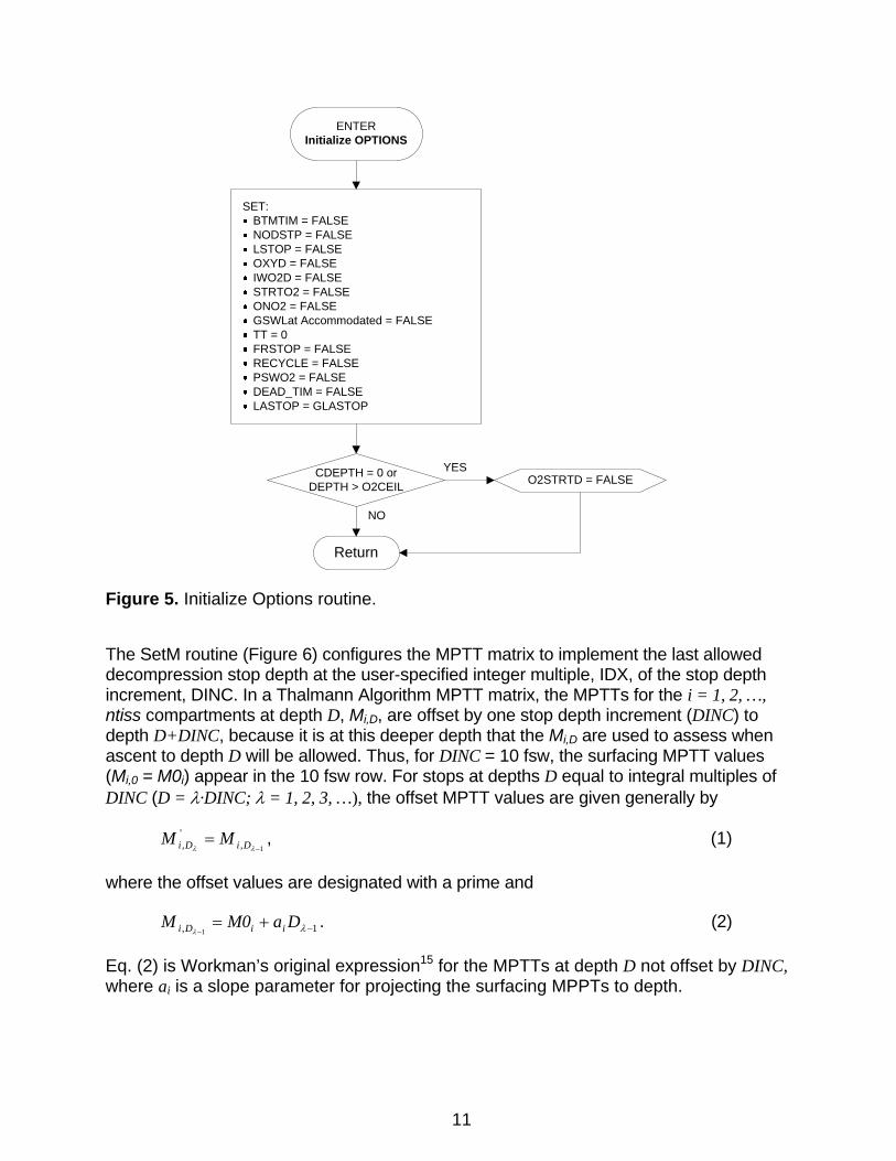
SET:BTMTIM = FALSENODSTP = FALSELSTOP = FALSEOXYD = FALSEIWO2D = FALSESTRTO2 = FALSEONO2 = FALSEGSWLat Accommodated = FALSETT = 0FRSTOP = FALSERECYCLE = FALSEPSWO2 = FALSEDEAD_TIM = FALSELASTOP = GLASTOP
Return
ENTERInitialize OPTIONS
CDEPTH = 0 orDEPTH > O2CEIL O2STRTD = FALSE
YES
NO
Figure 5. Initialize Options routine.
The SetM routine (Figure 6) configures the MPTT matrix to implement the last allowed decompression stop depth at the user-specified integer multiple, IDX, of the stop depth increment, DINC. In a Thalmann Algorithm MPTT matrix, the MPTTs for the i = 1, 2, …, ntiss compartments at depth D, Mi,D, are offset by one stop depth increment (DINC) to depth D+DINC, because it is at this deeper depth that the Mi,D are used to assess when ascent to depth D will be allowed. Thus, for DINC = 10 fsw, the surfacing MPTT values (Mi,0 = M0i) appear in the 10 fsw row. For stops at depths D equal to integral multiples of DINC (D = λ·DINC; λ = 1, 2, 3, …), the offset MPTT values are given generally by
1,, −=
λλ DiDi MM ' , (1)
where the offset values are designated with a prime and
1, 1 −+=− λλ
DaM0M iiDi . (2)
Eq. (2) is Workman’s original expression15 for the MPTTs at depth D not offset by DINC, where ai is a slope parameter for projecting the surfacing MPPTs to depth.
11
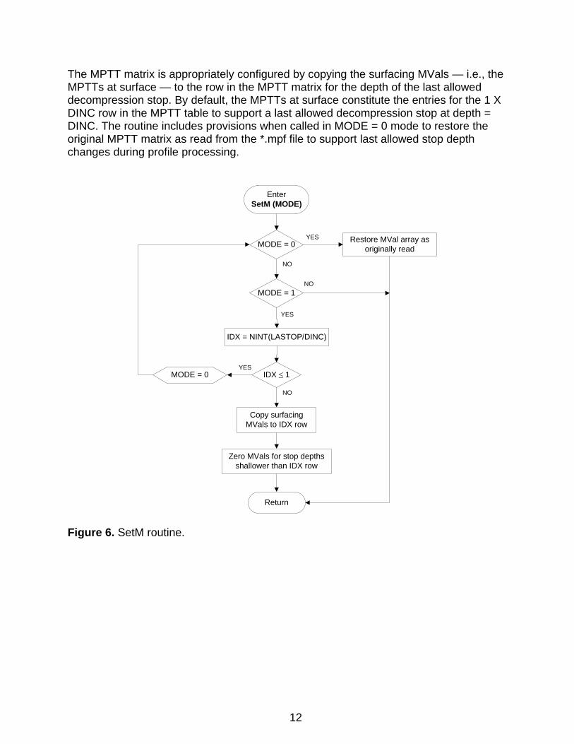
The MPTT matrix is appropriately configured by copying the surfacing MVals — i.e., the MPTTs at surface — to the row in the MPTT matrix for the depth of the last allowed decompression stop. By default, the MPTTs at surface constitute the entries for the 1 X DINC row in the MPTT table to support a last allowed decompression stop at depth = DINC. The routine includes provisions when called in MODE = 0 mode to restore the original MPTT matrix as read from the *.mpf file to support last allowed stop depth changes during profile processing.
EnterSetM (MODE)
Return
MODE = 0 Restore MVal array as originally read
MODE = 1
YES
NO
IDX = NINT(LASTOP/DINC)
IDX ≤ 1MODE = 0YES
Copy surfacing MVals to IDX row
Zero MVals for stop depths shallower than IDX row
YES
NO
NO
Figure 6. SetM routine.
12
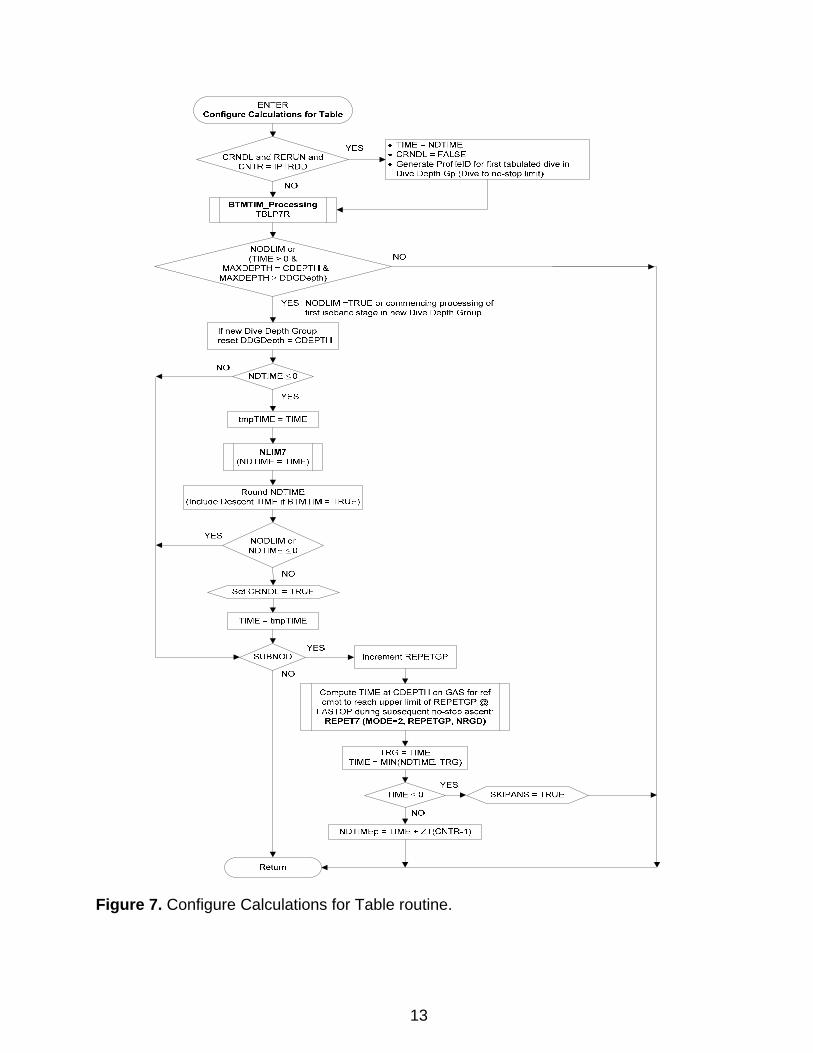
Figure 7. Configure Calculations for Table routine.
13
ENTER Configure Calculations for Table
YES • TIME= NDTIME • CRNDL =FALSE
::;>---~. Generate ProfileiD for ftrst tabulated dtve tn Dive Depth Gp (Dive to no-stop limit)
NO
YES NOD LIM =TRUE or commencing processing of first isobaric stage in new Dive Depth Group
,-----_L_-----,
(Include Descent TIME tf BTMTIM =TRUE)
Return
Compute TIME at CDEPTH on GAS for ref cmpt to reach upper limit of REPETGP@
I .ASTOP during subsequent no-stop ascent: REPET7 {MODE=Z, REPETGP, NRGD)
SKIPANS =TRUE
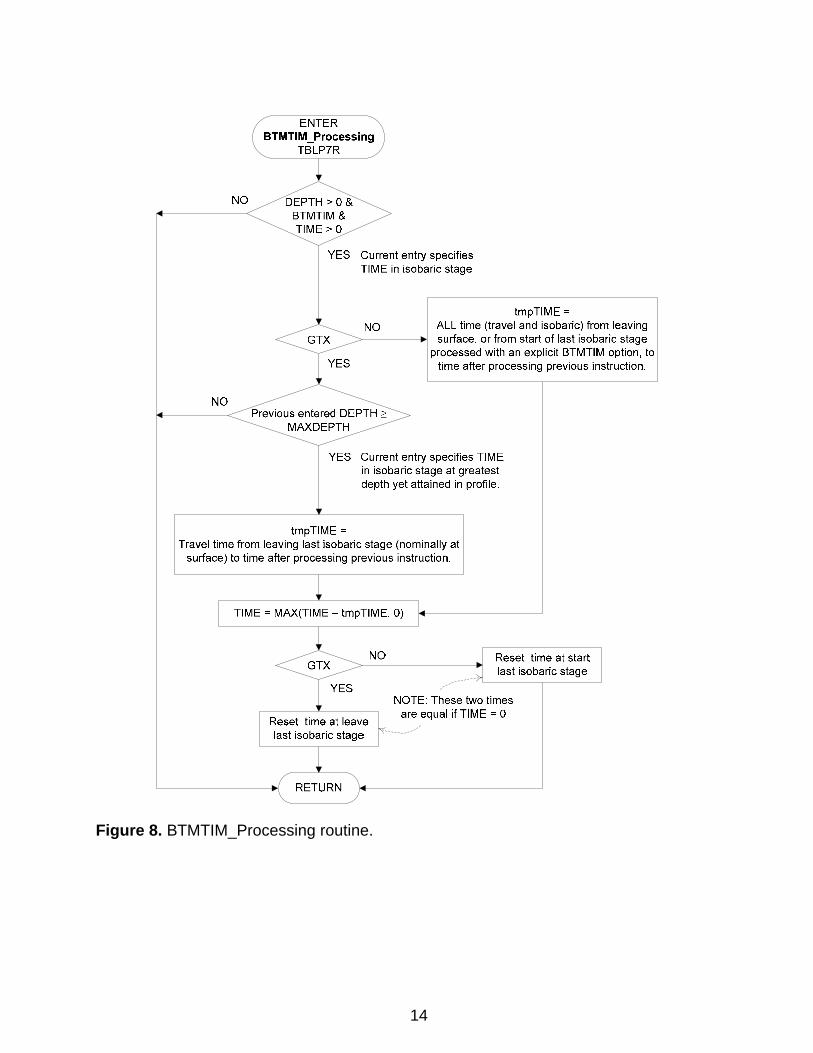
Figure 8. BTMTIM_Processing routine.
14
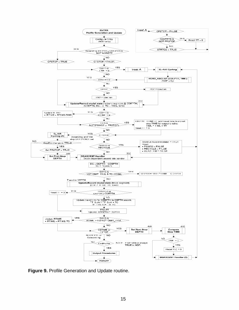
Figure 9. Profile Generation and Update routine.
15
YES
NO
Reset TT = o
YES
TBLP7R: If TIME>O, add travel time to stored stop TIME for output to table TIME= TIME+ TT
Reset TT = o
GSWLat Accommodated =TRUE Reset • PSW02 =FALSE • RECYCLE= FALSE • DEAD_ TIM= FALSE
DEPTH= RATE*RTJME + CDEPTH
End Profile is always TRUE in NDP.
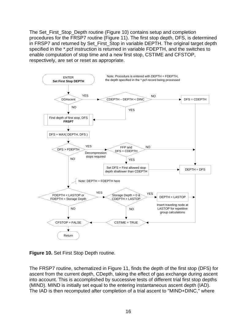
The Set_First_Stop_Depth routine (Figure 10) contains setup and completion procedures for the FRSP7 routine (Figure 11). The first stop depth, DFS, is determined in FRSP7 and returned by Set_First_Stop in variable DEPTH. The original target depth specified in the *.pcf instruction is returned in variable FDEPTH, and the switches to enable computation of stop time and a new first stop, CSTIME and CFSTOP, respectively, are set or reset as appropriate.
ENTERSet First Stop DEPTH
Find depth of first stop, DFSFRSP7
DFS > FDEPTH
FDEPTH < LASTOP orFDEPTH = Storage Depth
Set DFS = First allowed stop depth shallower than CDEPTH
YES
YES
Return
CFSTOP = FALSE
Storage Depth = 0 &CDEPTH > LASTOP DEPTH = LASTOP
NO
NO
YES
NOInsert traveling node at LASTOP for repetitive
group calculations
Note: Procedure is entered with DEPTH = FDEPTH, the depth specified in the *.pcf record being processed
DDAscent
NO
CDEPTH – DEPTH < DINC
DFS = MAX( DEPTH, DFS )
YES
YES
DFS = CDEPTHNO
FFP andDFS = CDEPTH
DEPTH = DFS
YES
NO
Decompression stops required
CSTIME = TRUE
Note: DEPTH = FDEPTH here
Figure 10. Set First Stop Depth routine.
The FRSP7 routine, schematized in Figure 11, finds the depth of the first stop (DFS) for ascent from the current depth, CDepth, taking the effect of gas exchange during ascent into account. This is accomplished by successive tests of different trial first stop depths (MIND). MIND is initially set equal to the entering instantaneous ascent depth (IAD). The IAD is then recomputed after completion of a trial ascent to "MIND+DINC," where
16
DINC is the stop depth increment. If the new IAD differs from the IAD before the trial ascent, the trial MIND is updated to this new value, and the IAD after ascent from CDepth to the new MIND is computed. The procedure is repeated until the IAD afteascent and MIND are equal. The first stop depth computed
r
by this procedure is never deeper than the entering
h s
CDepth if preceding ascents are executed with appropriate decompression stops. However, after an ascent without required decompression stops, the first stop deptfound in this routine, the IAD, may be deeper than the entering CDepth. In such casethe first stop depth is arbitrarily set equal to the entering CDepth, which may or may notbe an integer multiple of the stop depth increment, DINC. Otherwise, the first stop depth returned by FRSP7 is always an integer multiple of DINC.
17
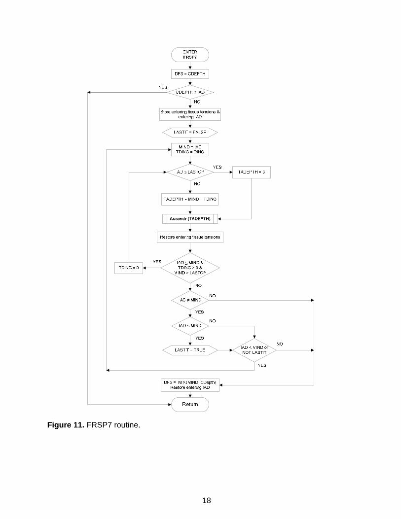
Figure 11. FRSP7 routine.
18
ENTERSet Next Stop DEPTH
Return
[CDEPTH - MAX( FDEPTH, LASTOP )] ≥ DINC
CSTIME
NO
YES
CDEPTH > LASTOP andFDEPTH < LASTOP
NO
DEPTH = LASTOPYES
DEPTH = FDEPTH
NO
Set DEPTH = nearest multiple of DINC < CDEPTH
YES
DDAscent andCDEPTH > Storage Depth + DINC and
FDEPTH < Storage Depth + DINC
NO
DEPTH = Storage Depth + DINCYES
CSTIME = FALSE
Insert traveling node at LASTOP for repetitive
group calculations
Figure 12. Set Next Stop Depth routine.
19
STRTO2 &TIME > 0 &
CDEPTH ≤ O2CEIL
GSWLat Accommodated orGSWLAT = 0
RTIME ≤ 0
GAS = O2(FN2 = 1 – O2TIME_FO2)(CPO2 = FALSE )
ONO2 = TRUERTIME = O2TIME – GSWLAT*STRTO2 = FALSEO2STRTD = TRUESet LineColor (NDP)
NO
Accommodate latency:PSWO2 = TRUETIME = GSWLATSet Linecolor (NDP)
NO
YES
YES
NO
GAS = O2(FN2 = 1–O2TIME_FO2)(CPO2 = FALSE )
ONO2 = TRUERTIME = O2TIMEDEAD_TIM = FALSESet LineColor (NDP)
ONO2
GAS = AIR(FN2 = AIR_FN2)(CPO2 = FALSE)
ONO2 = FALSERTIME = AIRTIMESet LineColor (NDP)
NO
TIME > RTIME
TIME = RTIMERECYCLE = TRUE
YES
YES
NO
YES
Return
*NOTE: Require GSWLAT < O2TIME
TIME ≤ 5 &CDEPTH = LASTOP
YES
NO
RTIME = O2TIME
AB_DEAD
NO
YES
Round TIME UP
ENTERO2-AIR Cycling
GSW_DEADNO
YES
Set FRSTOP = TRUE
O2STRTDYES
NO
ComputeStop TIME
DEAD_TIM = TRUE
RECYCLE = FALSE
DEAD_TIM = TRUE
Figure 13. O2-Air Cycling routine.
20
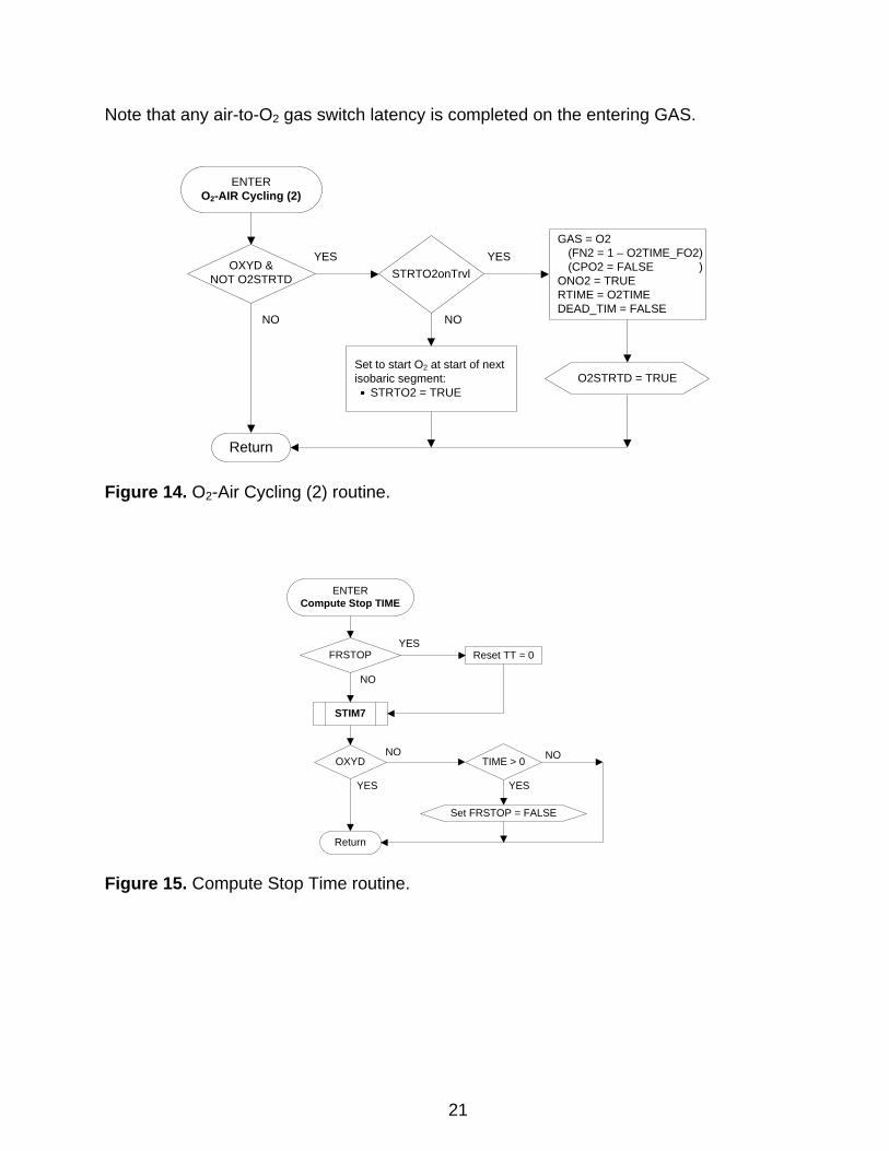
Note that any air-to-O2 gas switch latency is completed on the entering GAS.
Set to start O2 at start of next isobaric segment:
STRTO2 = TRUE
YESOXYD &
NOT O2STRTD
Return
NO
STRTO2onTrvl
GAS = O2(FN2 = 1 – O2TIME_FO2)(CPO2 = FALSE )
ONO2 = TRUERTIME = O2TIMEDEAD_TIM = FALSE
YES
NO
ENTERO2-AIR Cycling (2)
O2STRTD = TRUE
Figure 14. O2-Air Cycling (2) routine.
FRSTOP Reset TT = 0YES
NO
TIME > 0 NO
YES
OXYDNO
YES
STIM7
Return
ENTERCompute Stop TIME
Set FRSTOP = FALSE
Figure 15. Compute Stop Time routine.
21
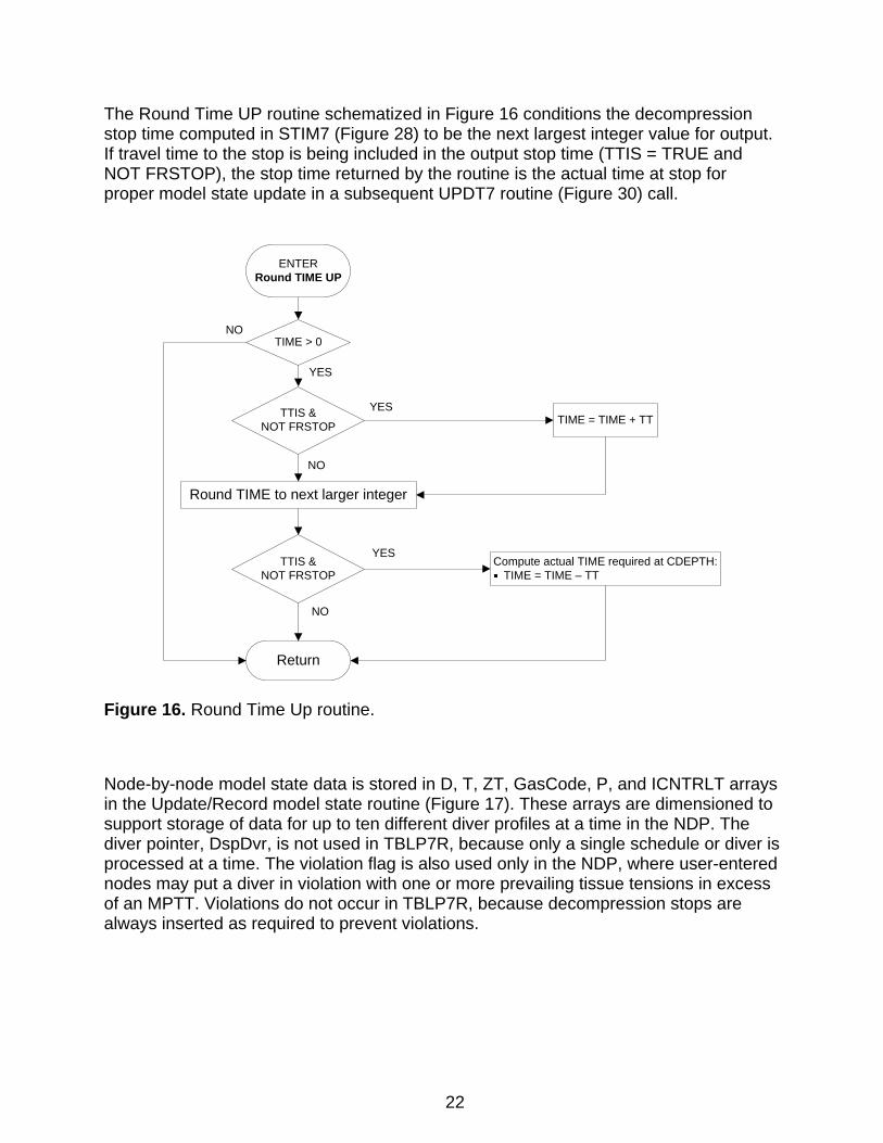
The Round Time UP routine schematized in Figure 16 conditions the decompression stop time computed in STIM7 (Figure 28) to be the next largest integer value for output. If travel time to the stop is being included in the output stop time (TTIS = TRUE and NOT FRSTOP), the stop time returned by the routine is the actual time at stop for proper model state update in a subsequent UPDT7 routine (Figure 30) call.
Return
TIME > 0NO
Round TIME to next larger integer
TTIS &NOT FRSTOP TIME = TIME + TT
NO
YES
Compute actual TIME required at CDEPTH:TIME = TIME – TT
NO
YES
YES
TTIS &NOT FRSTOP
ENTERRound TIME UP
Figure 16. Round Time Up routine.
Node-by-node model state data is stored in D, T, ZT, GasCode, P, and ICNTRLT arrays in the Update/Record model state routine (Figure 17). These arrays are dimensioned to support storage of data for up to ten different diver profiles at a time in the NDP. The diver pointer, DspDvr, is not used in TBLP7R, because only a single schedule or diver is processed at a time. The violation flag is also used only in the NDP, where user-entered nodes may put a diver in violation with one or more prevailing tissue tensions in excess of an MPTT. Violations do not occur in TBLP7R, because decompression stops are always inserted as required to prevent violations.
22

DEAD_TIM
NO
YES
Store end-segment data (row CNTR in storage array):DEPTH D([DspDvr,] CNTR)TIME (Differential) T([DspDvr,] CNTR)TIME (Elapsed) ZT([DspDvr,] CNTR)GAS (GASCODE) GASCODE([DspDvr,] CNTR)*Compartmental gas tensions P([DspDvr,] CNTR, i=1,NumTiss)ICNTRLT ICNTRLT([DspDvr,] CNTR)
Return
ENTERUpdate/Record model state
UPDT7(CDEPTH, DC, TC, GAS)Update compartmental gas tensions
FCNTRLT (MODE=0)Determine controlling tissue, ICNTRLT
Advance CNTR for next entry:CNTR = CNTR + 1
RCRD7
NOTE: DspDvr subscriptused only in NDP
*The ANS GASCODE is generated from the prevailing NCODE and, depending on the CPO2 setting, PO2 or FN2 value.
CDepth < IAD Set Violation Flag for current end node
Clear Violation Flag for current end node
NO
YES
Figure 17. Update/Record Model State routine.
The Ascendr routine (Figure 18) supports the NLIM7 and FRSP7 routines by effecting a no-stop ascent from the prevailing depth (CDepth) to the passed target depth (TDepth) or the surfacing dropout depth, whichever is deeper, while accommodating rig-specific depth-dependent changes in inspired gas and ascent rate, in order to compute the instantaneous ascent depth (IAD) after the ascent in UPDT7. Thus, for ascents to TDepth=0, Ascendr returns with IAD evaluated on the basis of compartmental gas tensions after ascent to the depth less than or equal to LASTOP appropriate to the LST_DOMode setting.
23

NOTE: The model state must be saved in the calling routine before Ascendr is called and restored after the Ascendr call. This model state save/restore is not handled in Ascendr because, in principle, the model state includes the computed IAD for return to the calling routine.
24
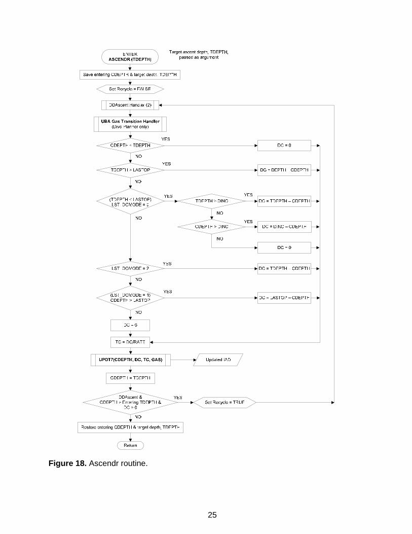
Figure 18. Ascendr routine.
25
ENTER ASCENDR (TDEPTH}
Target ascent depth, TDEPTH, passed as argument
Save entering CDEPTH & target depth, TDEPTH
(LST_DOMODE = 1} CDEPTH > LASTOP
DC= DING- CDEPTH
DC=O
YES ~>---------------~DC= TDEPTH- CDEPTH
YES >--------------~DC= LASTOP- CDEPTH
Updated lAD
Set Recycle = TRUE
Restore entering CDEPTH & target depth, TDEPTH
Return
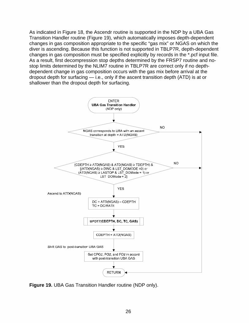
As indicated in Figure 18, the Ascendr routine is supported in the NDP by a UBA Gas Transition Handler routine (Figure 19), which automatically imposes depth-dependent changes in gas composition appropriate to the specific “gas mix” or NGAS on which the diver is ascending. Because this function is not supported in TBLP7R, depth-dependent changes in gas composition must be specified explicitly by records in the *.pcf input file. As a result, first decompression stop depths determined by the FRSP7 routine and no-stop limits determined by the NLIM7 routine in TBLP7R are correct only if no depth-dependent change in gas composition occurs with the gas mix before arrival at the dropout depth for surfacing — i.e., only if the ascent transition depth (ATD) is at or shallower than the dropout depth for surfacing.
Figure 19. UBA Gas Transition Handler routine (NDP only).
26
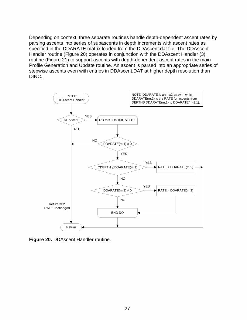
Depending on context, three separate routines handle depth-dependent ascent rates by parsing ascents into series of subascents in depth increments with ascent rates as specified in the DDARATE matrix loaded from the DDAscent.dat file. The DDAscent Handler routine (Figure 20) operates in conjunction with the DDAscent Handler (3) routine (Figure 21) to support ascents with depth-dependent ascent rates in the main Profile Generation and Update routine. An ascent is parsed into an appropriate series of stepwise ascents even with entries in DDAscent.DAT at higher depth resolution than DINC.
ENTERDDAscent Handler
Return
DDAscent
NO
DDARATE(m,1) ≠ 0
CDEPTH ≤ DDARATE(m,1) RATE = DDARATE(m,2)
NO
YES
YES
DDARATE(m,2) ≠ 0 RATE = DDARATE(m,2)
NO
NO
YES
YES
NOTE: DDARATE is an mx2 array in which DDARATE(m,2) is the RATE for ascents from DEPTHS DDARATE(m,1) to DDARATE(m-1,1).
DO m = 1 to 100, STEP 1
END DO
Return withRATE unchanged
Figure 20. DDAscent Handler routine.
27
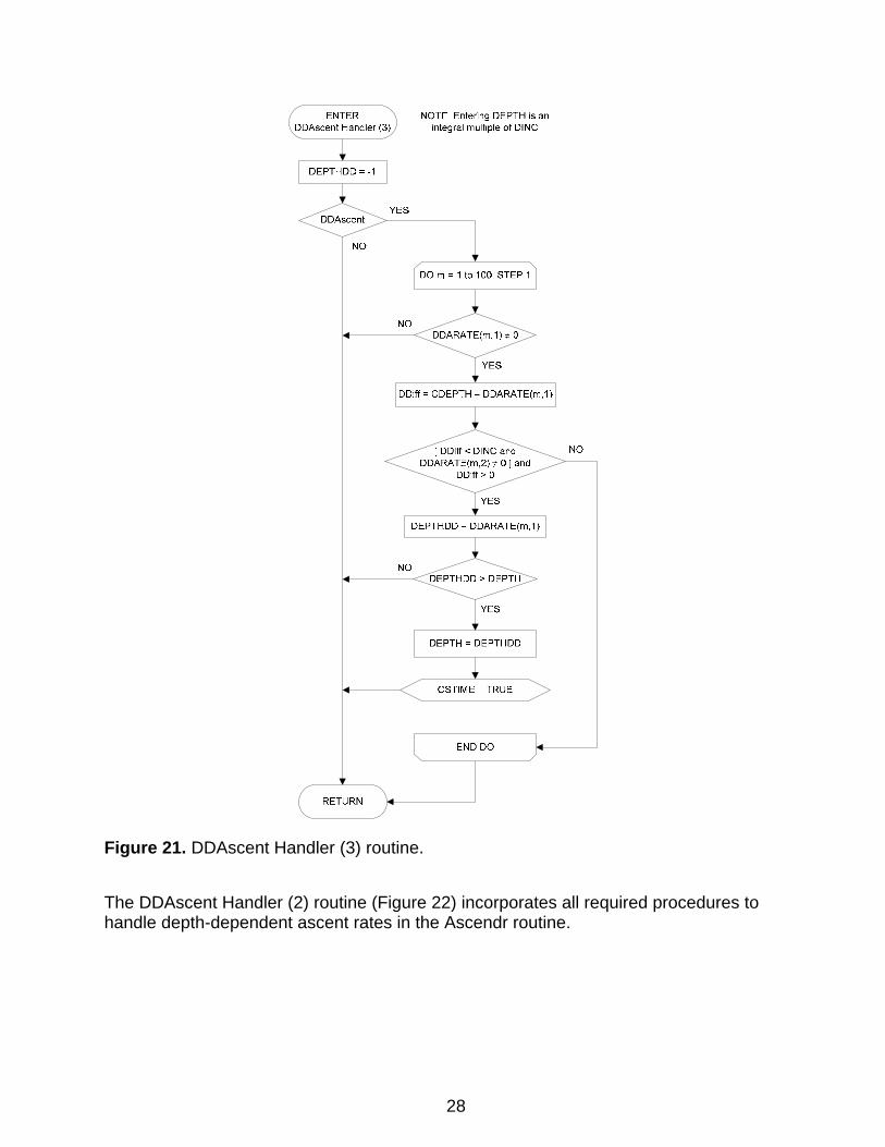
Figure 21. DDAscent Handler (3) routine.
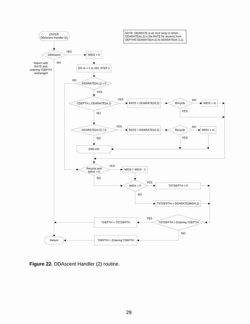
The DDAscent Handler (2) routine (Figure 22) incorporates all required procedures to handle depth-dependent ascent rates in the Ascendr routine.
28
ENTERDDAscent Handler (2)
Return
DDAscent
NO
DDARATE(m,1) ≠ 0
CDEPTH ≤ DDARATE(m,1) RATE = DDARATE(m,2)
NO
YES
YES
Recycle MIDX = m
YES
DDARATE(m,2) ≠ 0 RATE = DDARATE(m,2)
NO
NO
NO
Recycle
YES
NO
Recycle andMIDX > 0
YES
YES
MIDX ≤ 0 TSTDEPTH = 0
TSTDEPTH = DDARATE(MIDX,1)
YES
MIDX = MIDX - 1
YESNO
NO
TDEPTH = TSTDEPTH TSTDEPTH > Entering TDEPTH
TDEPTH = Entering TDEPTH
YES
NO
MIDX = m
NOTE: DDARATE is an mx2 array in which DDARATE(m,2) is the RATE for ascents from DEPTHS DDARATE(m,1) to DDARATE(m-1,1).
DO m = 1 to 100, STEP 1
END DO
MIDX = 0
Return withRATE and
entering TDEPTH unchanged
Figure 22. DDAscent Handler (2) routine.
29
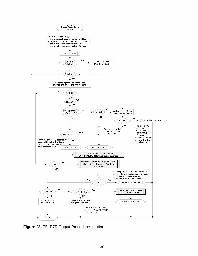
Figure 23. TBLP7R Output Procedures routine.
30
ENTER Output Procedures
TBLP7R
Set pointers to nodes @ • end of deepest isobaric seg.,-.,nt, IPTRDD • beginning of first decompression stop, IPTRFS • end of first decompression stop, IPTREFS • end of last decompression stop, IPTRELS
Return
Compute repetrtive gp designators REPET7 (MODE=1, REPETGP, NRGD)
Record no-stop l1rn1t profile for the dive
depth group
Write Schedule to Main Table file [FCNTRL T(MODE•1) for RGD output suppression!
Translate schedule into Augmented NMRI Standard format & wnte to •.ANS file.
OutputANS
Set RERUN= TRUC
First profile w/ a decompression s1op in the dive
depth group. Compute and
record rl()-S.top limit profile fer the dive
depth group.
NO YES
Just comp[eted recording first no-stop limit profile in the dive depth group_ Reprocess
profile as originally entered. (Rqd backspace in PCF file completed above.)
Continue S U BNOD Table processing wlnext REPETGP
at current DEPTH.
Set RERUN = FALSE
Set SUBNOD =FALSE
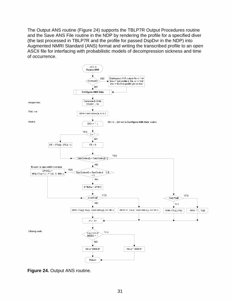
The Output ANS routine (Figure 24) supports the TBLP7R Output Procedures routine and the Save ANS File routine in the NDP by rendering the profile for a specified diver (the last processed in TBLP7R and the profile for passed DspDvr in the NDP) into Augmented NMRI Standard (ANS) format and writing the transcribed profile to an open ASCII file for interfacing with probabilistic models of decompression sickness and time of occurrence.
Figure 24. Output ANS routine.
31
Header line
First line
Nodes
Ensure no gas switch overlaps
STIMEu = MIN( ZTu(i+1)- ZTu(i), STIME)
Closing node
ENTER
NOTE: j defined in Configure ANS Data routine
YES
Write ZTu(i), Du(i), GasCodeu(i), STIMEu
YES
Return
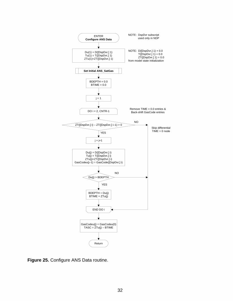
DO i = 2, CNTR-1
ZT([DspDvr,] i) – ZT([DspDvr,] i–1) > 0
j = j+1
Du(j) = D([DspDvr,] i)Tu(j) = T([DspDvr,] i)
ZTu(j)=ZT([DspDvr,] i)GasCodeu(j–1) = GasCode([DspDvr,] i)
END DO i
NO
YES
Skip differential TIME = 0 node
j = 1
ENTERConfigure ANS Data
Return
Du(j) > BDEPTH
BDEPTH = Du(j)BTIME = ZTu(j)
BDEPTH = 0.0BTIME = 0.0
NO
YES
GasCodeu(j) = GasCodeu(0)TASC = ZTu(j) – BTIME
NOTE: D([DspDvr,] 1) = 0.0T([DspDvr,] 1) = 0.0ZT([DspDvr,] 1) = 0.0
from model state initialization
Remove TIME = 0.0 entries &Back-shift GasCode entries
Set Initial ANS_SatGas
Du(1) = D([DspDvr,] 1)Tu(1) = T([DspDvr,] 1)
ZTu(1)=ZT([DspDvr,] 1)
NOTE: DspDvr subscriptused only in NDP
Figure 25. Configure ANS Data routine.
32
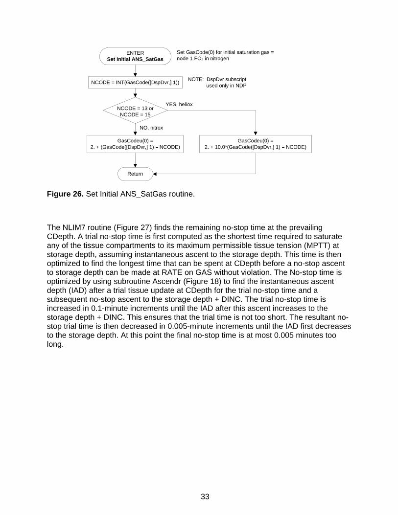
NCODE = INT(GasCode([DspDvr,] 1))
NCODE = 13 or NCODE = 15
GasCodeu(0) = 2. + 10.0*(GasCode([DspDvr,] 1) NCODE)
GasCodeu(0) = 2. + (GasCode([DspDvr,] 1) NCODE)
YES, heliox
NO, nitrox
ENTERSet Initial ANS_SatGas
Set GasCode(0) for initial saturation gas = node 1 FO2 in nitrogen
Return
NOTE: DspDvr subscriptused only in NDP
Figure 26. Set Initial ANS_SatGas routine.
The NLIM7 routine (Figure 27) finds the remaining no-stop time at the prevailing CDepth. A trial no-stop time is first computed as the shortest time required to saturate any of the tissue compartments to its maximum permissible tissue tension (MPTT) at storage depth, assuming instantaneous ascent to the storage depth. This time is then optimized to find the longest time that can be spent at CDepth before a no-stop ascent to storage depth can be made at RATE on GAS without violation. The No-stop time is optimized by using subroutine Ascendr (Figure 18) to find the instantaneous ascent depth (IAD) after a trial tissue update at CDepth for the trial no-stop time and a subsequent no-stop ascent to the storage depth + DINC. The trial no-stop time is increased in 0.1-minute increments until the IAD after this ascent increases to the storage depth + DINC. This ensures that the trial time is not too short. The resultant no-stop trial time is then decreased in 0.005-minute increments until the IAD first decreases to the storage depth. At this point the final no-stop time is at most 0.005 minutes too long.
33
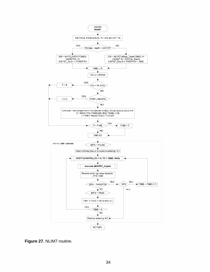
Figure 27. NLIM7 routine.
34
Set PA02, PANZ (min 0) for GAS at CDEPTH
YES
IDX ~ NINT(FstStop_DepthiDINC) +1 TADEPTH ~ FstStop_Depth
1/\DTST _Depth~ TADCPTH + DING
ComputeT for compartment ito saturate to M(I,IDX) on G/\S at CDEPTH A~ MAX( {P(1}-PAN2)1(M(i,IDX}-PAN2), Ul)
T ~ (HLFTM(1)1(l0G(2)) • LOG(A)
Refine TIME estimate
UPDT7 (CDEPTH, DC= 0, TC =TIME, GAS)
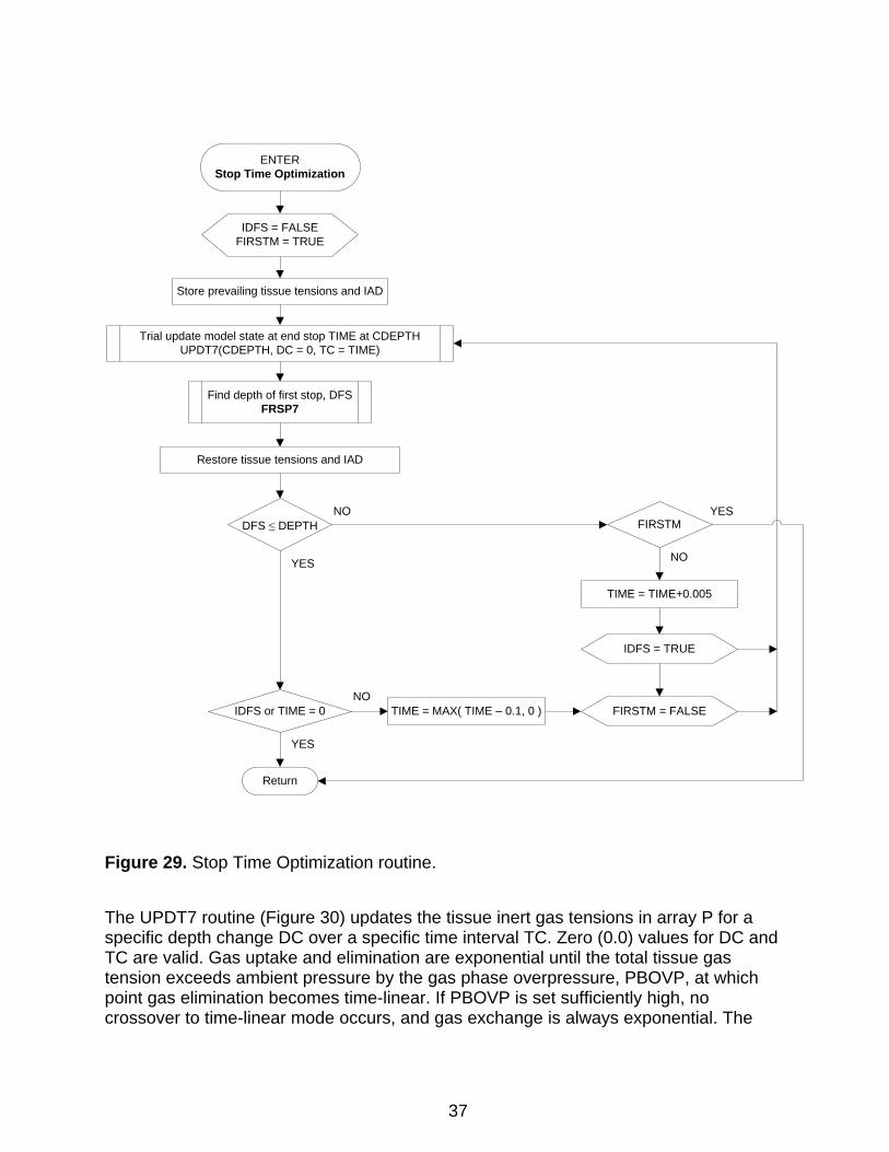
The STIM7 routine (Figure 28) finds the time required at the current depth, CDepth, before a violation-free ascent to Depth can be executed. Such an ascent is possible only after time has been spent at CDepth sufficient to wash out all tissues to gas tensions less than or equal to the maximum permissible tissue tensions in the appropriate row IJ of array M. The row IJ is computed from the target Depth. If Depth is not an integer multiple of DINC, IJ is computed to point to the row in MPTT array M for the next shallower integer multiple of the stop depth increment, DINC. The normal mode is for the next stop to be one DINC shallower than CDepth. When the next stop is more than one DINC shallower than CDepth, the initially computed stop time is shortened in the Stop Time Optimization routine (Figure 29) to take advantage of the compartmental gas washout that occurs during ascent from CDepth to Depth + DINC.
35
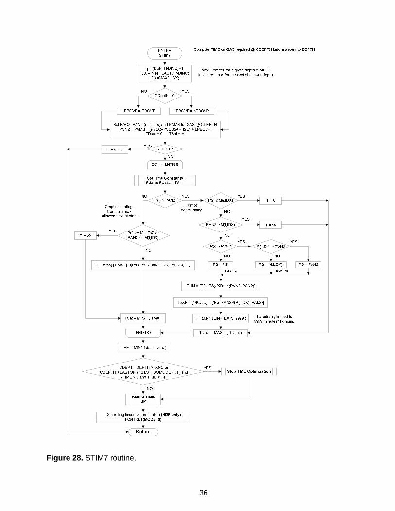
Figure 28. STIM7 routine.
36
Compute TIMF on GAS required@ CDFPTH before ascent to DFPTH
MVAL entries for a given depth in MPTT table are those for the next shallower depth
NO YES
Set PA02, PAN2 (min= OJ, and PAMB for GAS@ CDEPTH PVN2 = PAMB- (PV02+PVC02+PH20) + LPBOVP
TIME= 0
Cmpt saturatmg Compute max
allowed time at stop
YES
TDsat = O: TSat = 'l)
NO
T =MAX[ [1/KSat}ln[(P(i)-PAN2)/(M(i,IDX)-PAN2)], 0]
YES
YES
TLIN = (P(i)-PS)/[KDsat·(PVN2-PAN2)]
TEXP = ]1/KDsat]-ln[(PS-PAN2J/(M(i,IDX)-PAN2)]
T=O
YES
T arbitrarily l1m1ted to 9999 mmute maximum
]CDEPTH-DCPTH > DINC or (CDFPTII ::: I.ASTOP and I ST _ DOMODE -t lJ ] and
(TIME> 0 and TIME< co)
Controlling tissue determination (NDP only) FCNTRL T(MOOE=O)
Return
YES Stop TIME Optimiz01tion
PS = PVN2
ENTERStop Time Optimization
Store prevailing tissue tensions and IAD
Trial update model state at end stop TIME at CDEPTHUPDT7(CDEPTH, DC = 0, TC = TIME)
Restore tissue tensions and IAD
Find depth of first stop, DFSFRSP7
DFS ≤ DEPTH
IDFS = FALSEFIRSTM = TRUE
FIRSTM
Return
NO
FIRSTM = FALSE
YES
IDFS or TIME = 0
YES
TIME = TIME+0.005
IDFS = TRUE
NO
YES
NOTIME = MAX( TIME – 0.1, 0 )
Figure 29. Stop Time Optimization routine.
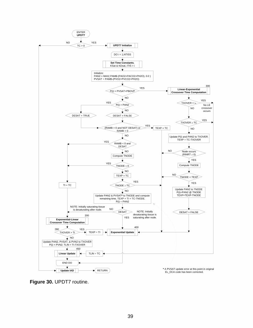
The UPDT7 routine (Figure 30) updates the tissue inert gas tensions in array P for a specific depth change DC over a specific time interval TC. Zero (0.0) values for DC and TC are valid. Gas uptake and elimination are exponential until the total tissue gas tension exceeds ambient pressure by the gas phase overpressure, PBOVP, at which point gas elimination becomes time-linear. If PBOVP is set sufficiently high, no crossover to time-linear mode occurs, and gas exchange is always exponential. The
37
location of a PVSAT update error in d with an asterisk. The erroneous expression PV
original EL_DCA code1,5 is indicateTNODE*RINRT PVSAT SAT += has been
replaced with the correct expression, TNODE*RAMB PVSAT PVSAT += .
ASYM models, in which different exponential time constants apply for gas uptakgas elimination, are also supported in this routine through nonunitary values of SDR(TISS) [SDR(TISS) ≠ 1.0]. The transition between the two time constants is alwaysmade at a compartmental gas tension minimum or ma
e and
ximum to avoid introducing any
iscontinuity in the slope of the exponential function. d
38
ENTERUPDT7
DO i = 1,NTISS
Initialize:PAN2 = MAX( PAMB-(PAO2+PACO2+PH2O), 0.0 )PVSAT = PAMB-(PVO2+PVCO2+PH2O)
P(i) > PVSAT+PBOVPYES
P(i) > PAN2
DESAT = TRUE DESAT = FALSE
(RAMB > 0 and NOT DESAT) orRAMB = 0
RAMB < 0 andDESAT
Compute TNODE
TNODE ≤ 0
300
TNODE ≥ TC
400
Update PAN2 & PVSAT* to TNODE and compute remaining time, TEXP = TI = TC-TNODE.
P(i) = PAN2
Exponential Update
Exponential-Linear Crossover Time Computation
YES
YES
YES
Linear-Exponential Crossover Time Computation
YES
DESATNO
YES200
TXOVER > TI
Linear Update
TXOVER ≥ TCYES
Update P(i) and PAN2 to TXOVER.TEXP = TC-TXOVER
YES
Update IAD RETURN
YES
END DO
NO
NO
NO
NO
NO
NO
NO
NO
450
TNODE < TEXP
Update PAN2 to TNODEP(i)=PAN2 @ TNODETEXP=TEXP-TNODE
YES
NO
TEXP = TI
Update PAN2, PVSAT, & PVN2 to TXOVERP(i) = PVN2; TLIN = TI-TXOVER
TLIN = TC
TI = TC
TEXP = TC
Node occurs(RINRT ≠ 0)
Compute TNODE
NO
YES
YES
NO
NOTE: Initially saturating tissue is desaturating after node.
NOTE: Initially desaturating tissue is saturating after node.
TC > 0NO YES
Set Time Constants,KSat & KDsat, ITIS = i
TEXP = TC
280
DESAT = FALSE
* A PVSAT update error at this point in original EL_DCA code has been corrected.
TXOVER = No LE
crossover occurs
UPDT7 Initialize
Figure 30. UPDT7 routine.
39
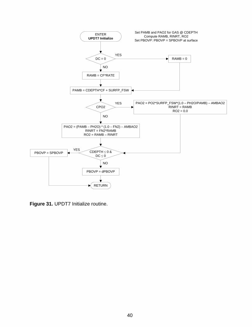
Set PAMB and PAO2 for GAS @ CDEPTHCompute RAMB, RINRT, RO2
Set PBOVP: PBOVP = SPBOVP at surface
ENTERUPDT7 Initialize
DC = 0 RAMB = 0
RAMB = CF*RATE
PAMB = CDEPTH*CF + SURFP_FSW
CPO2PAO2 = PO2*SURFP_FSW*(1.0 – PH2O/PAMB) – AMBAO2
RINRT = RAMBRO2 = 0.0
YES
YES
PAO2 = (PAMB – PH2O) * (1.0 – FN2) – AMBAO2RINRT = FN2*RAMB
RO2 = RAMB – RINRT
NO
NO
CDEPTH ≤ 0 &DC ≤ 0
PBOVP = SPBOVPYES
PBOVP = dPBOVP
RETURN
NO
Figure 31. UPDT7 Initialize routine.
40
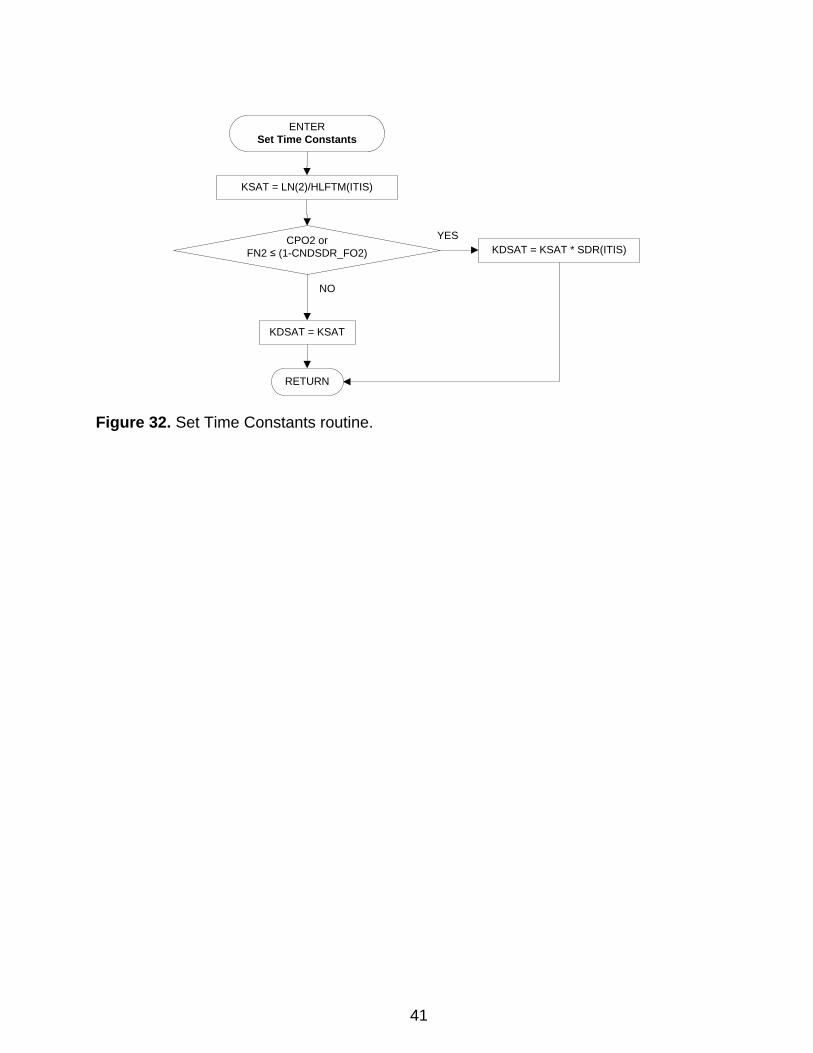
KDSAT = KSAT
CPO2 or FN2 ≤ (1-CNDSDR_FO2) KDSAT = KSAT * SDR(ITIS)
YES
NO
ENTERSet Time Constants
RETURN
KSAT = LN(2)/HLFTM(ITIS)
Figure 32. Set Time Constants routine.
41

The Exponential-Linear Crossover Time Computation Procedure (Figure 33) computes TXOVER, the time at which the tissue being processed will transition from the initial exponential desaturation mode to the linear desaturation mode. This crossover occurs at the time when the total tissue gas tension exceeds the total ambient pressure by the gas phase overpressure (PBOVP). TXOVER is initially assumed equal to the entering TI set in the calling routine, UPDT7. In constant PO2 mode (CPO2 = TRUE), the rate of ambient pressure change, RAMB, and the rate of inert gas tension change, RINRT, are equal, and TXOVER can be found analytically. In constant inert fraction mode (CPO2 = FALSE), RAMB and RINRT are not equal, and TXOVER must be found by numerical iteration. In the latter case, the constant PO2 solution is used as a starting value for the iterative solution.
Figure 33. Exponential-Linear Crossover Time Computation routine.
42
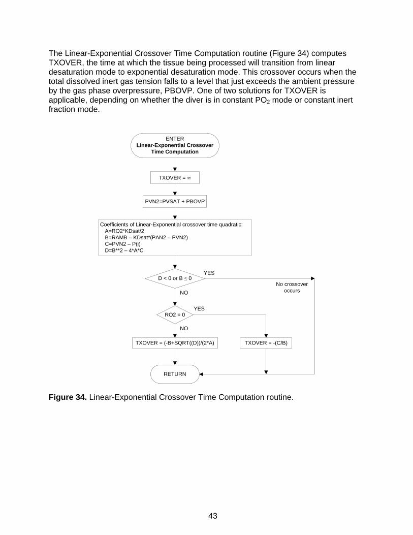
The Linear-Exponential Crossover Time Computation routine (Figure 34) computes TXOVER, the time at which the tissue being processed will transition from linear desaturation mode to exponential desaturation mode. This crossover occurs when the total dissolved inert gas tension falls to a level that just exceeds the ambient pressure by the gas phase overpressure, PBOVP. One of two solutions for TXOVER is applicable, depending on whether the diver is in constant PO2 mode or constant inert fraction mode.
ENTERLinear-Exponential Crossover
Time Computation
PVN2=PVSAT + PBOVP
Coefficients of Linear-Exponential crossover time quadratic:A=RO2*KDsat/2B=RAMB – KDsat*(PAN2 – PVN2)C=PVN2 – P(i)D=B**2 – 4*A*C
D < 0 or B ≤ 0
RETURN
YES
RO2 = 0
TXOVER = -(C/B)
YES
TXOVER = (-B+SQRT((D))/(2*A)
NO
NO
No crossover occurs
TXOVER = ∞
Figure 34. Linear-Exponential Crossover Time Computation routine.
43
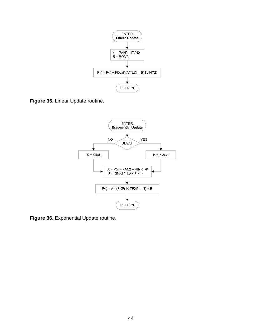
Figure 35. Linear Update routine.
Figure 36. Exponential Update routine.
44
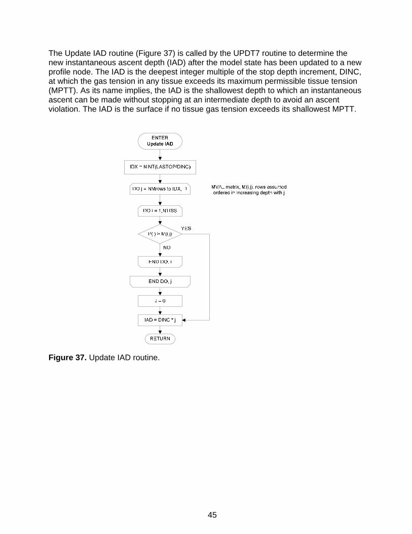
The Update IAD routine (Figure 37) is called by the UPDT7 routine to determine the new instantaneous ascent depth (IAD) after the model state has been updated to a new profile node. The IAD is the deepest integer multiple of the stop depth increment, DINC, at which the gas tension in any tissue exceeds its maximum permissible tissue tension (MPTT). As its name implies, the IAD is the shallowest depth to which an instantaneous ascent can be made without stopping at an intermediate depth to avoid an ascent violation. The IAD is the surface if no tissue gas tension exceeds its shallowest MPTT.
Figure 37. Update IAD routine.
45

ENTERFCNTRLT (MODE)
MODE= 0 = 1
ICNTRLT is slowest tissue with prevailing gas tension
in excess of its MVAL.
ij = (CDEPTH/DINC)+1IDX = NINT(LASTOP/DINC)
IDX=MAX(ij,IDX)
IDX = NINT(LASTOP/DINC)
DO i = 1,NTISS
END DO
P(i) > M(i,IDX)
ICNTRLT = i
YES
NO
RGD_SPPRSS > 0
SRF_CNTRLT_MODE
YES
ICNTRLT is tissue with gas tension closest to its MVAL at end of last stop.
= 1
ICNTRLT is slowest tissue
with gas tension in excess of its
MVAL at beginning of last
stop.
= 0
ICNTRLT = 0
RETURN
NO
NOTE: M(i,j) assumed in order of increasing half time from i = 1 to NTISS
Finding ICNTRLT for RGD output suppression
in TBLP7R
DO i = 1,NTISS
TDP < DPMIN
DPMIN = ∞
END DO
TDP = |P(i) @ end last stop – M(i,IDX)|
DPMIN = TDPICNTRLT = i
YES
NO
DO i = CNTR – 1, 1, -1
END DO
DEPTH(i) ≤ LASTOP
ICNTRLT = Stored ICNTRLT(i)
YES
NO
Figure 38. FCNTRLT routine.
Subroutine FCNTRLT (Figure 38) determines the tissue, ICNTRLT, that controls the time at a decompression stop. The appropriate definition of ICNTRLT depends on the application specified by the MODE setting in the FCNTRLT call. In MODE = 0 mode, ICNTRLT is determined as the tissue compartment that controls the time at a decompression stop on the basis of prevailing compartmental gas tensions at the start of
46
the stop. In MODE = 1 mode, ICNTRLT is determined as the tissue compartment that controls whether a repetitive group designator (RGD) will be included with a computed decompression schedule in an output table. Subroutine FCNTRLT is called in MODE = 1 mode only by the TBLP7R Output Procedures routine (Figure 23) after each computed schedule is complete with the diver at surface. In this mode FCNTRLT determines ICNTRLT as the controlling tissue compartment for surfacing, depending on the SRF_CNTRLT_MODE switch setting from the initialization file:
• SRF_CNTRLT_MODE = 0: The controlling compartment for surfacing is the highest half time (slowest) compartment that had a gas tension in excess of its surfacing M-Val when the diver arrived at the last decompression stop depth during ascent.
• SRF_CNTRLT_MODE = 1: The controlling compartment for surfacing is the compartment that had gas tension closest to its surfacing M-Val when the diver left the last decompression stop depth during ascent.
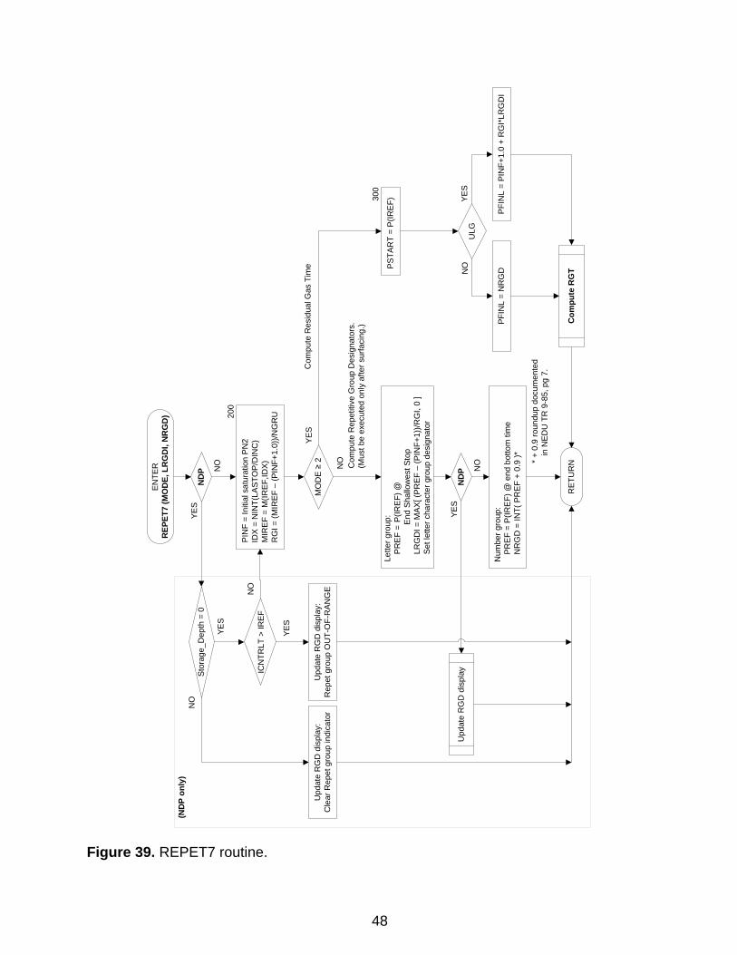
An RGD is then included with the schedule in the output table only if ICNTRLT is less than or equal to the reference tissue, IREF (i.e., only if ICNTRLT points to a tissue compartment with a gas exchange half-time faster than or equal to that of the reference tissue). Subroutine FCNTRLT is called in MODE = 0 mode in the Update/Record Model State routine (Figure 17) in TBLP7R, or at the end of the STIM7 routine (Figure 28) in the NDP, as each decompression stop is processed. In the NDP, the returned value of the controlling tissue, ICNTRLT, is then used in the REPET7 routine (Figure 39) to determine the prevailing RGD for display. A value of ICNTRLT = 0 is returned for no-stop ascents reflecting that no tissue controls because all tissue gas tensions during traverse through the last stop depth are less than corresponding surfacing MVALs). The RGD for each schedule is determined in subroutine REPET7 (Figure 39). Original EL-DCA subroutines for computation of surfacing repetitive groups, surface interval credit tables, and residual nitrogen times for repetitive diving are described in Thalmann.4 Detailed code for the modules from which the REPET7 routine is adapted is given in an accompanying untitled technical memorandum.5 The diver is presumed to be at surface when this routine is called. REPET7 is only called in MODE = 0 mode in the NDP.
47
EN
TER
REP
ET7
(MO
DE,
LR
GD
I, N
RG
D)
ULG
PFIN
L =
NR
GD
PFI
NL
= PI
NF+
1.0
+ R
GI*
LRG
DI
YE
SN
O
Com
pute
RG
TPSTA
RT
= P
(IRE
F)
PIN
F =
Initi
al s
atur
atio
n PN
2ID
X =
NIN
T(LA
STO
P/D
INC
)M
IRE
F =
M(IR
EF,ID
X)
RG
I = (M
IREF
–(P
INF+
1.0)
)/NG
RU
MO
DE
≥ 2
300
YE
S
Lette
r gro
up:
PR
EF
=P
(IRE
F) @
End
Shal
low
est S
top
LRG
DI =
MAX
[ (P
RE
F –
(PIN
F+1)
)/RG
I, 0
]Se
t let
ter c
hara
cter
gro
up d
esig
nato
r
Com
pute
Rep
etiti
ve G
roup
Des
igna
tors
.(M
ust b
e ex
ecut
ed o
nly
afte
r sur
faci
ng.)
Com
pute
Res
idua
l Gas
Tim
e
RET
UR
NNO
200
Num
ber g
roup
:P
RE
F =
P(IR
EF)
@ e
nd b
otto
m ti
me
NR
GD
= IN
T( P
REF
+ 0
.9 )* * +
0.9
roun
dup
docu
men
ted
in N
EDU
TR
9-8
5, p
g 7.
Upd
ate
RG
D d
ispl
ayN
DP
YE
S
NO
ND
PY
ES
NO
Stor
age_
Dep
th =
0
YES
ICN
TRLT
> IR
EF
Upd
ate
RG
D d
ispl
ay:
Rep
et g
roup
OU
T-O
F-R
ANG
EU
pdat
e R
GD
dis
play
:C
lear
Rep
et g
roup
indi
cato
r
NO
YES
NO
(ND
P on
ly)
Figure 39. REPET7 routine.
48
ENTER
Compute RGT
PAMB = CDEPTH*CF + SURFP_FSW
CPO2
PAO2 = (PAMB–PH2O)*(1–FN2) – AMBAO2 PAO2 = PO2 * SURFP_FSW * (1–PH2O/PAMB) – AMBAO2
PAN2 = MAX( PAMB – (PAO2+PACO2+PH2O), 0.0 )
YESNO
PFINL ≥ PAN2 TRG =
PSTART ≥ PFINL TRG = 0
TRG = (1/KSAT)*LN((PSTART–PAN2)/(PFINL–PAN2))
YES
YES
NO
NO
TIME = TRG
RETURN
(SUBNOD and ULG and CDEPTH > LASTOP) or(NOT SUBNOD and RNTMODE = 1)
Compute and add effect of ascent to LASTOP:
Ascnd4RGT
YES
NO
Truncate TIME to nearest lower integerSUBNOD
YES
NO
Round TIME UP
Save entering TTIS;Temporarily set TTIS = FALSE
Restore entering TTIS
If TRG > 0 then add descent travel time
TIME > 0 & TIME < ∞
NO
YES
Subtractdescent travel time
Figure 40. Compute RGT routine.
49
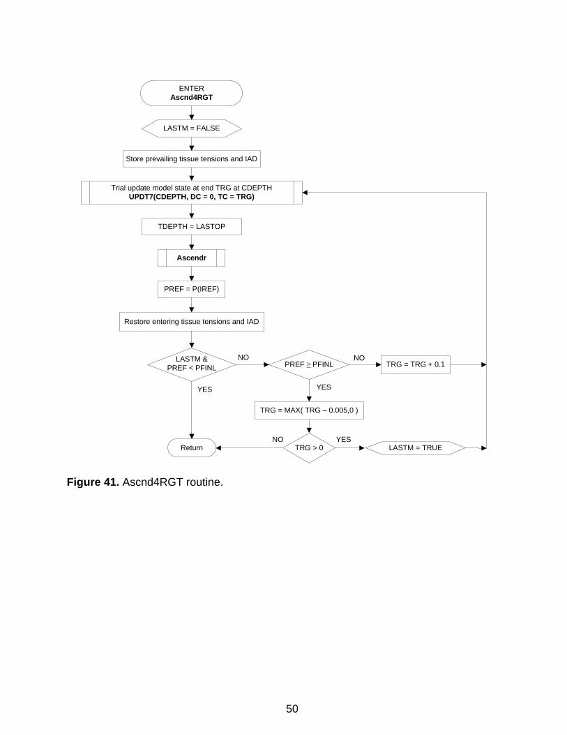
ENTER
Ascnd4RGT
Store prevailing tissue tensions and IAD
Trial update model state at end TRG at CDEPTHUPDT7(CDEPTH, DC = 0, TC = TRG)
LASTM &PREF < PFINL
LASTM = FALSE
PREF ≥ PFINL
Return
NO
YES
TRG = TRG + 0.1
YES
TRG = MAX( TRG – 0.005,0 )
NO
NO
Ascendr
TDEPTH = LASTOP
Restore entering tissue tensions and IAD
PREF = P(IREF)
LASTM = TRUETRG > 0YES
Figure 41. Ascnd4RGT routine.
50
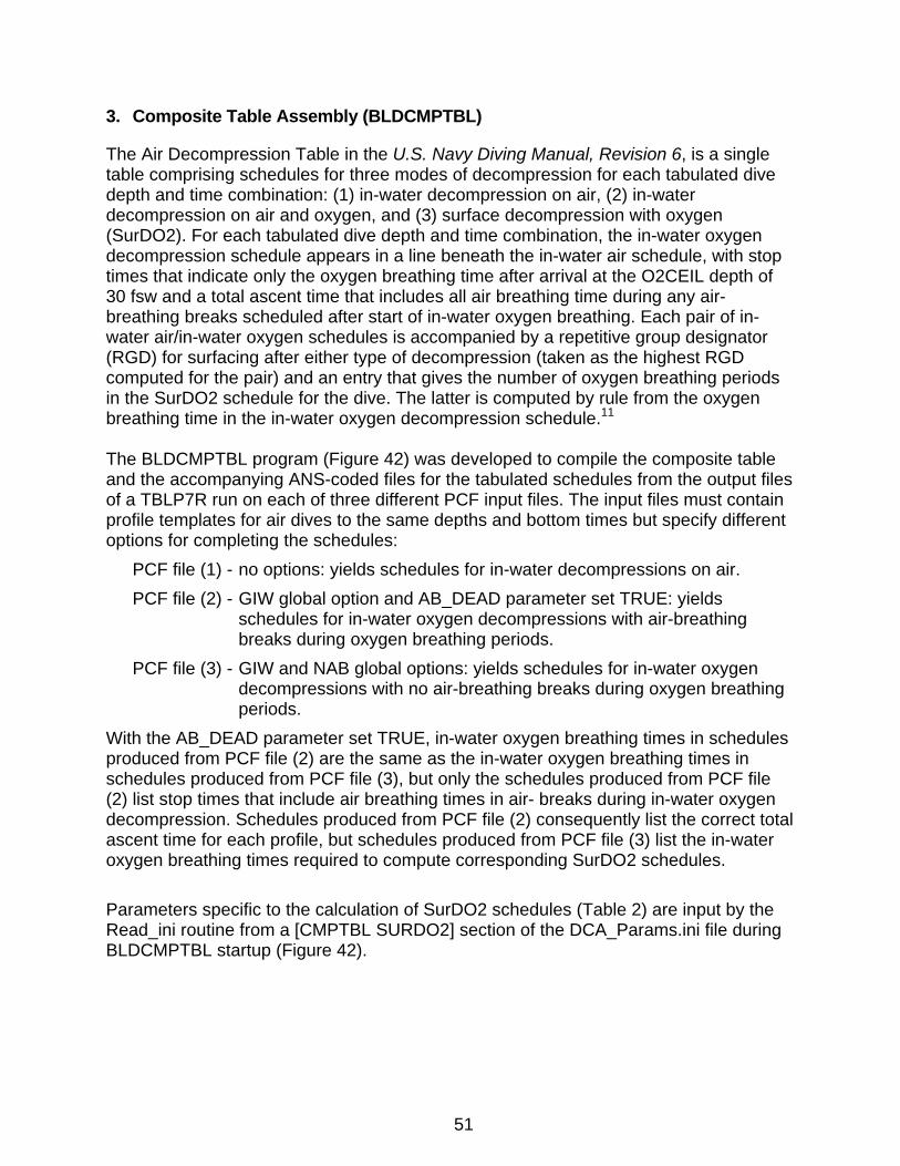
3. Composite Table Assembly (BLDCMPTBL)
The Air Decompression Table in the U.S. Navy Diving Manual, Revision 6, is a single table comprising schedules for three modes of decompression for each tabulated dive depth and time combination: (1) in-water decompression on air, (2) in-water decompression on air and oxygen, and (3) surface decompression with oxygen (SurDO2). For each tabulated dive depth and time combination, the in-water oxygen decompression schedule appears in a line beneath the in-water air schedule, with stop times that indicate only the oxygen breathing time after arrival at the O2CEIL depth of 30 fsw and a total ascent time that includes all air breathing time during any air-breathing breaks scheduled after start of in-water oxygen breathing. Each pair of in-water air/in-water oxygen schedules is accompanied by a repetitive group designator (RGD) for surfacing after either type of decompression (taken as the highest RGD computed for the pair) and an entry that gives the number of oxygen breathing periods in the SurDO2 schedule for the dive. The latter is computed by rule from the oxygen breathing time in the in-water oxygen decompression schedule.11 The BLDCMPTBL program (Figure 42) was developed to compile the composite table and the accompanying ANS-coded files for the tabulated schedules from the output files of a TBLP7R run on each of three different PCF input files. The input files must contain profile templates for air dives to the same depths and bottom times but specify different options for completing the schedules:
PCF file (1) - no options: yields schedules for in-water decompressions on air. PCF file (2) - GIW global option and AB_DEAD parameter set TRUE: yields
schedules for in-water oxygen decompressions with air-breathing breaks during oxygen breathing periods.
PCF file (3) - GIW and NAB global options: yields schedules for in-water oxygen decompressions with no air-breathing breaks during oxygen breathing periods.
With the AB_DEAD parameter set TRUE, in-water oxygen breathing times in schedules produced from PCF file (2) are the same as the in-water oxygen breathing times in schedules produced from PCF file (3), but only the schedules produced from PCF file (2) list stop times that include air breathing times in air- breaks during in-water oxygen decompression. Schedules produced from PCF file (2) consequently list the correct total ascent time for each profile, but schedules produced from PCF file (3) list the in-water oxygen breathing times required to compute corresponding SurDO2 schedules. Parameters specific to the calculation of SurDO2 schedules (Table 2) are input by the Read_ini routine from a [CMPTBL SURDO2] section of the DCA_Params.ini file during BLDCMPTBL startup (Figure 42).
51
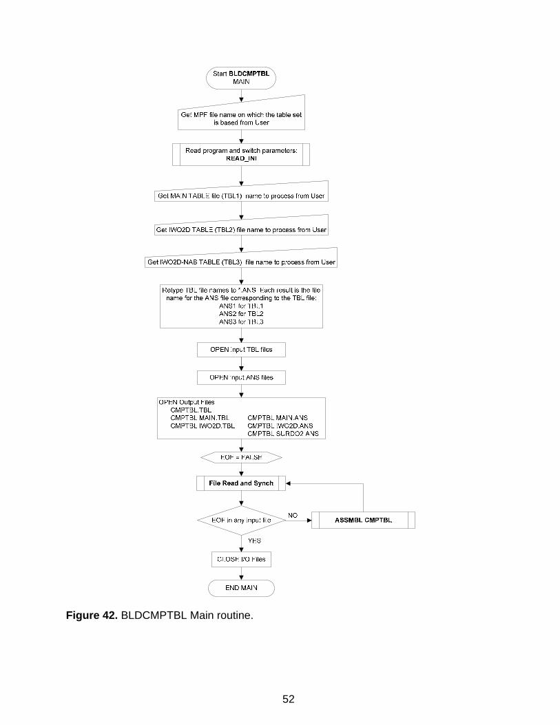
Figure 42. BLDCMPTBL Main routine.
52
Start BLDCMPTBL MAIN
Get MPF file name on which the table set is based from User
Read program and switch parameters READ_INI
Get MAIN TABLE file (TBL 1) name to process from User
Get IW02D TABLE (TBL2) file name to process from User
Get IW02D-NAB TABLE (TBL3) file name to process from User
Retype TBL file names to *.ANS. Each result is the file name for the ANS file corresponding to the TBL file:
ANS1 forTBL1 ANS2 for TBL2 ANS3 for TBL3
OPEN Output Files: CMPTBL.TBL CMPTBL MAIN.TBL CMPTBL IW02D.TBL
CMPTBL MAIN.ANS CMPTBL IW02D.ANS CMPTBL SURD02.ANS
ASSMBL CMPTBL
Table 2. SurDO2 Parameters
(Loaded by READ_INI routine from [CMPTBL SURDO2] section of program initialization file at program startup]
Parameter Description
AIRTIME Maximum air breathing time (min) in an oxygen-air cycle during oxygen breathing in SurD
CARATE Chamber ascent rate
CDRATE Chamber descent rate
DrpOut_ARATE Ascent rate for dropout to surface during SurD initiation
DrpOut_DEPTH Depth from which to initiate SurD and dropout to surface
SurDTimFctr Multiplier for computed O2 breathing times in SurDO2 schedules
O2TIME Maximum oxygen breathing time (min) in an oxygen-air cycle during oxygen breathing in SurD
O2TIME_FO2 Fraction of oxygen in inspired gas during oxygen breathing in SurD
53
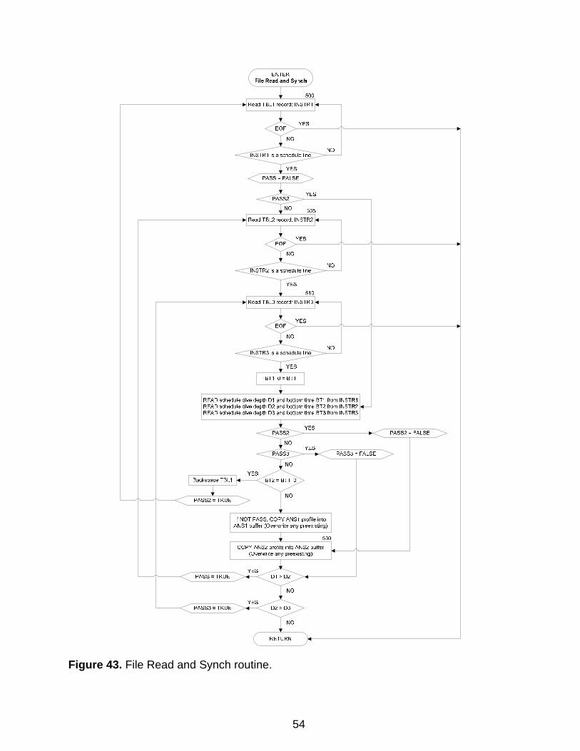
Figure 43. File Read and Synch routine.
54
ENTER File Read and Synch
READ schedule dive depth D1 and bottom time BT1 from INSTR1 READ schedule dive depth D2 and bottom time BT2 from INSTR2 READ schedule dive depth D3 and bottom time BT3 from INSTR3
PASS3 = FALSE
RETURN
PASS2 = FALSE
RETURN
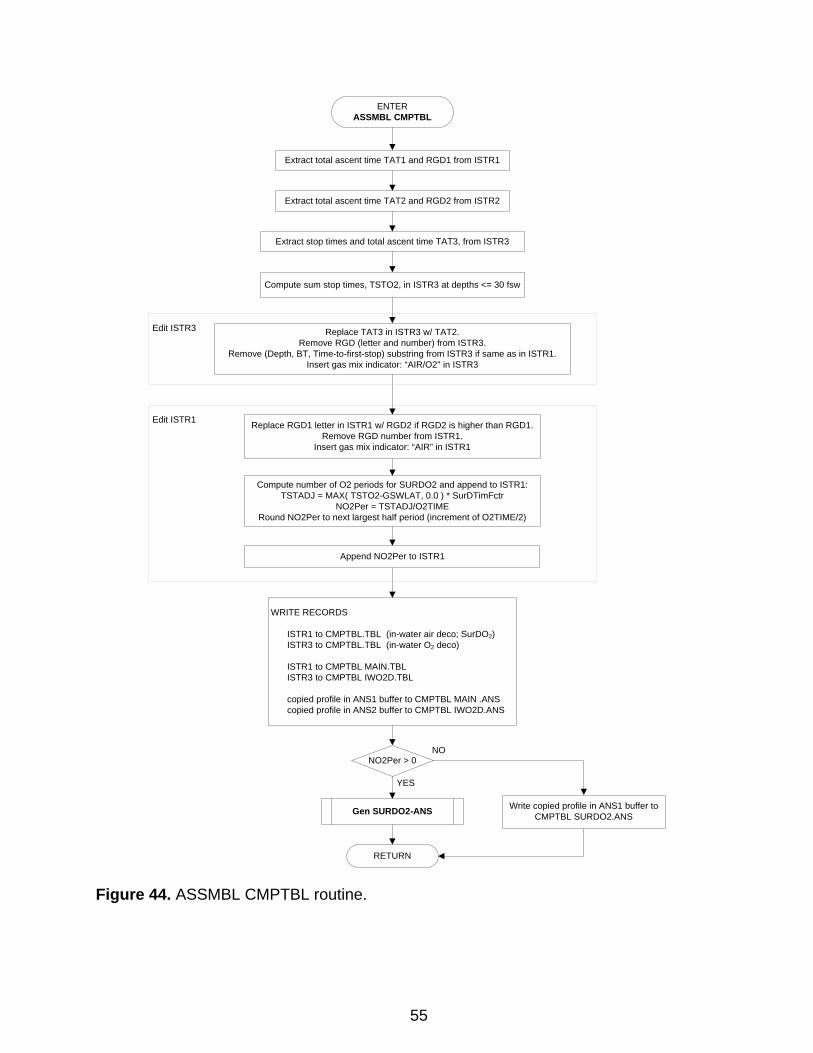
ENTERASSMBL CMPTBL
Extract total ascent time TAT1 and RGD1 from ISTR1
Extract total ascent time TAT2 and RGD2 from ISTR2
Extract stop times and total ascent time TAT3, from ISTR3
Compute sum stop times, TSTO2, in ISTR3 at depths <= 30 fsw
Replace TAT3 in ISTR3 w/ TAT2.Remove RGD (letter and number) from ISTR3.
Remove (Depth, BT, Time-to-first-stop) substring from ISTR3 if same as in ISTR1.Insert gas mix indicator: “AIR/O2" in ISTR3
Edit ISTR3
Edit ISTR1 Replace RGD1 letter in ISTR1 w/ RGD2 if RGD2 is higher than RGD1.Remove RGD number from ISTR1.
Insert gas mix indicator: “AIR” in ISTR1
Compute number of O2 periods for SURDO2 and append to ISTR1:TSTADJ = MAX( TSTO2-GSWLAT, 0.0 ) * SurDTimFctr
NO2Per = TSTADJ/O2TIMERound NO2Per to next largest half period (increment of O2TIME/2)
WRITE RECORDS
ISTR1 to CMPTBL.TBL (in-water air deco; SurDO2)ISTR3 to CMPTBL.TBL (in-water O2 deco)
ISTR1 to CMPTBL MAIN.TBLISTR3 to CMPTBL IWO2D.TBL
copied profile in ANS1 buffer to CMPTBL MAIN .ANScopied profile in ANS2 buffer to CMPTBL IWO2D.ANS
Append NO2Per to ISTR1
Gen SURDO2-ANS Write copied profile in ANS1 buffer to CMPTBL SURDO2.ANS
NO2Per > 0
YES
NO
Figure 44. ASSMBL CMPTBL routine.
55
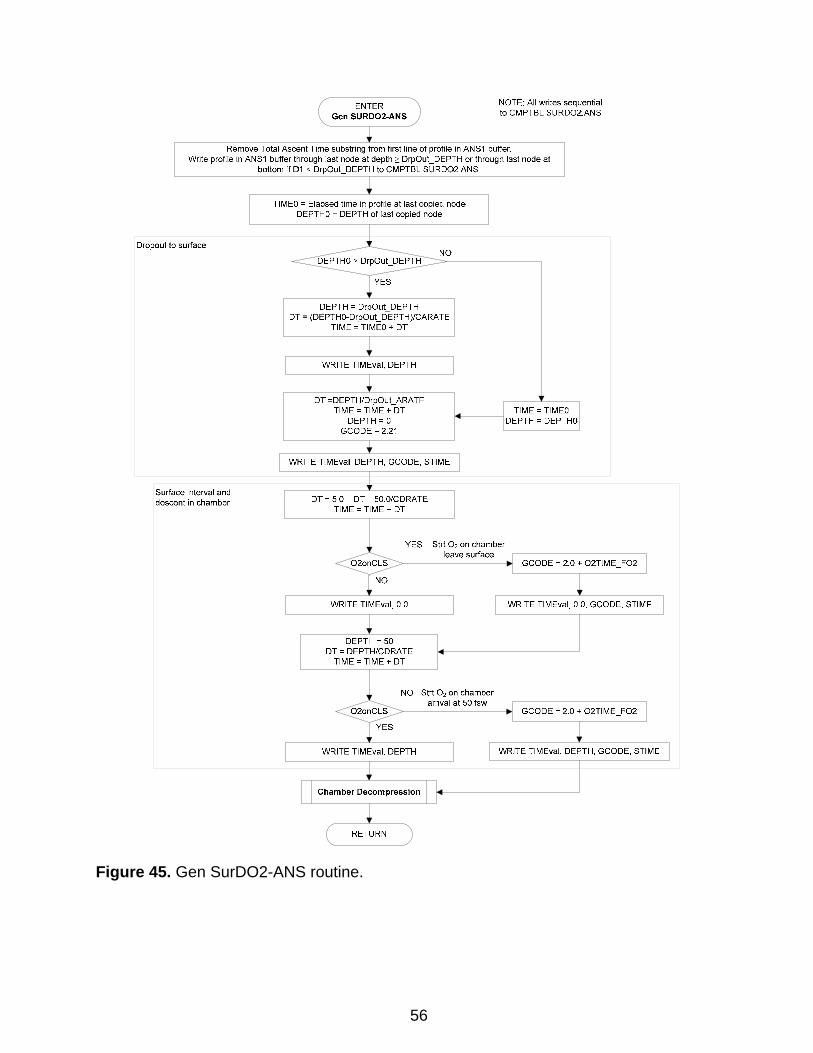
Figure 45. Gen SurDO2-ANS routine.
56
ENTER Gen SURD02-ANS
NOTE: All writes sequential to CMPTBL SURD02.ANS
Remove Total Ascent Time substring from first line of profile in ANS1 buffer. Write profile in ANS1 buffer through last node at depth;.. DrpOut_DEPTH or through last node at
bottom if D1 < DrpOut_DEPTH to CMPTBL SURD02.ANS.
Dropout to surface
Surface interval and descent in chamber
TIMED= Elapsed time in profile at last copied node DEPTHD = DEPTH of last copied node
NO
DEPTH= DrpOut_DEPTH DT = (DEPTHO-DrpOut_DEPTH)ICARATE
TIME =TIMED+ DT
WRITE TIMEval. DEPTH
DT =DEPTH/DrpOut_ ARA TE TIME= TIME+ DT
DEPTH= D GCODE = 2.21
WRITE TIMEval. DEPTH. GCODE. STIME
DT = 5.D- DT- 50.0/CDRATE TIME= TIME+ DT
YES Strt 0, on chamber leave surface
TIME=TIMED DEPTH = DEPTHD
WRITE TIMEval, D.O WRITE TIMEval, O.D, GCODE, STIME
WRITE TIMEval, DEPTH
RETURN
Strt O, on chamber arrival at 50 fsw
WRITE TIMEval, DEPTH, GCODE, STIME
RETURN
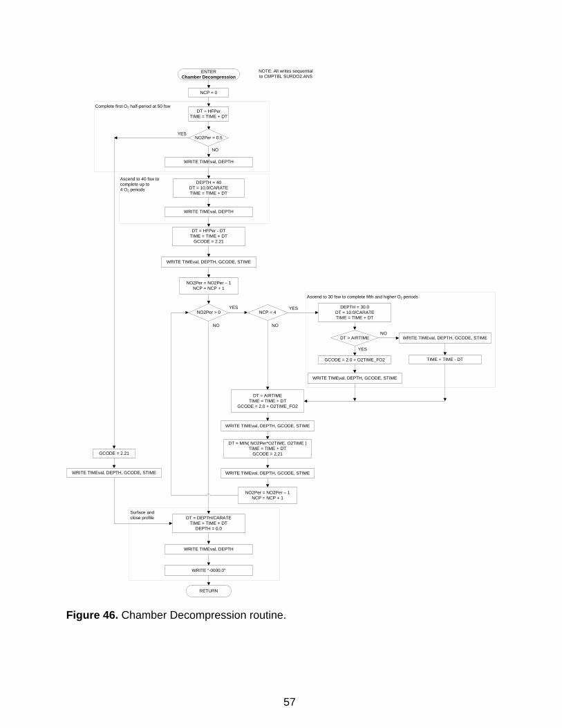
DT = HFPerTIME = TIME + DT
NO2Per = 0.5YES
NO
ENTERChamber Decompression
DEPTH = 40DT = 10.0/CARATETIME = TIME + DT
WRITE TIMEval, DEPTH
DT = HFPer - DTTIME = TIME + DT
GCODE = 2.21
WRITE TIMEval, DEPTH, GCODE, STIME
NO2Per = NO2Per – 1NCP = NCP + 1
NO2Per > 0 NCP = 4YES
DT = DEPTH/CARATETIME = TIME + DT
DEPTH = 0.0
WRITE TIMEval, DEPTH
DT = AIRTIMETIME = TIME + DT
GCODE = 2.0 + O2TIME_FO2
WRITE TIMEval, DEPTH, GCODE, STIME
DT = MIN( NO2Per*O2TIME, O2TIME )TIME = TIME + DT
GCODE = 2.21
WRITE TIMEval, DEPTH, GCODE, STIME
NO2Per = NO2Per – 1NCP = NCP + 1
YES DEPTH = 30.0DT = 10.0/CARATETIME = TIME + DT
DT > AIRTIME
GCODE = 2.0 + O2TIME_FO2
WRITE TIMEval, DEPTH, GCODE, STIME
YES
WRITE TIMEval, DEPTH, GCODE, STIME
NO
NO
TIME = TIME - DT
NO
WRITE “-0000.0”
NCP = 0
Ascend to 30 fsw to complete fifth and higher O2 periods
Complete first O2 half-period at 50 fsw
Ascend to 40 fsw tocomplete up to4 O2 periods
Surface andclose profile
WRITE TIMEval, DEPTH
NOTE: All writes sequential to CMPTBL SURDO2.ANS
GCODE = 2.21
WRITE TIMEval, DEPTH, GCODE, STIME
Figure 46. Chamber Decompression routine.
57
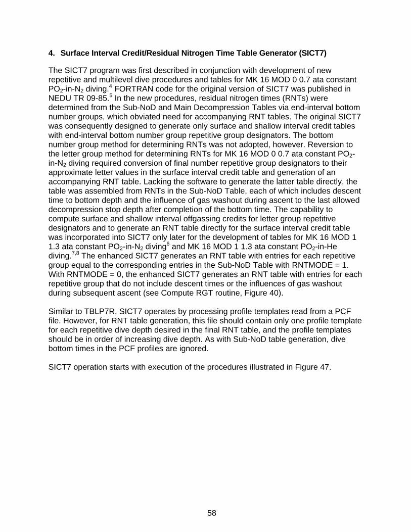
4. Surface Interval Credit/Residual Nitrogen Time Table Generator (SICT7)
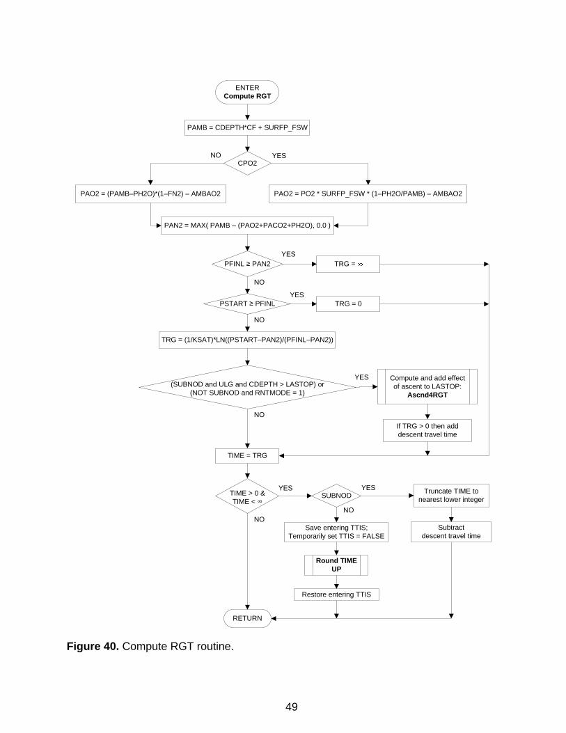
The SICT7 program was first described in conjunction with development of new repetitive and multilevel dive procedures and tables for MK 16 MOD 0 0.7 ata constant PO2-in-N2 diving.4 FORTRAN code for the original version of SICT7 was published in NEDU TR 09-85.5 In the new procedures, residual nitrogen times (RNTs) were determined from the Sub-NoD and Main Decompression Tables via end-interval bottom number groups, which obviated need for accompanying RNT tables. The original SICT7 was consequently designed to generate only surface and shallow interval credit tables with end-interval bottom number group repetitive group designators. The bottom number group method for determining RNTs was not adopted, however. Reversion to the letter group method for determining RNTs for MK 16 MOD 0 0.7 ata constant PO2-in-N2 diving required conversion of final number repetitive group designators to their approximate letter values in the surface interval credit table and generation of an accompanying RNT table. Lacking the software to generate the latter table directly, the table was assembled from RNTs in the Sub-NoD Table, each of which includes descent time to bottom depth and the influence of gas washout during ascent to the last allowed decompression stop depth after completion of the bottom time. The capability to compute surface and shallow interval offgassing credits for letter group repetitive designators and to generate an RNT table directly for the surface interval credit table was incorporated into SICT7 only later for the development of tables for MK 16 MOD 1 1.3 ata constant PO2-in-N2 diving6 and MK 16 MOD 1 1.3 ata constant PO2-in-He diving.7,8 The enhanced SICT7 generates an RNT table with entries for each repetitive group equal to the corresponding entries in the Sub-NoD Table with RNTMODE = 1. With RNTMODE = 0, the enhanced SICT7 generates an RNT table with entries for each repetitive group that do not include descent times or the influences of gas washout during subsequent ascent (see Compute RGT routine, Figure 40). Similar to TBLP7R, SICT7 operates by processing profile templates read from a PCF file. However, for RNT table generation, this file should contain only one profile template for each repetitive dive depth desired in the final RNT table, and the profile templates should be in order of increasing dive depth. As with Sub-NoD table generation, dive bottom times in the PCF profiles are ignored. SICT7 operation starts with execution of the procedures illustrated in Figure 47.
58
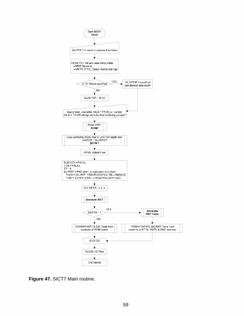
Figure 47. SICT7 Main routine.
59
StartSICT7 MAIN
OPEN PCF file and read Setup Data: • MPIF filename • UNITS, DINC, Global Switch settings
GLASTOP =specified last allowed stop depth
Query User: Use letter (ULG =TRUE} or number (ULG =FALSE} designators for final surfacing groups?
Copy surfacing MVAL row to LASTOP depth row: LASTOP = GLASTOP
SETM 1
SUBNOD =FALSE TTIS =FALSE TT= 0 Set PINF = PN2 when air-saturated at surface:
PA02 = (SURFP _FSW-PH20)*(1--0. 79}- AMBA02 PINF = SURFP _FSW- (PA02+PAC02+PH20}
END MAIN
FORMAT/WRITE SIC/RNT Table from contents of RTIM, RNTD, & RNT matrices
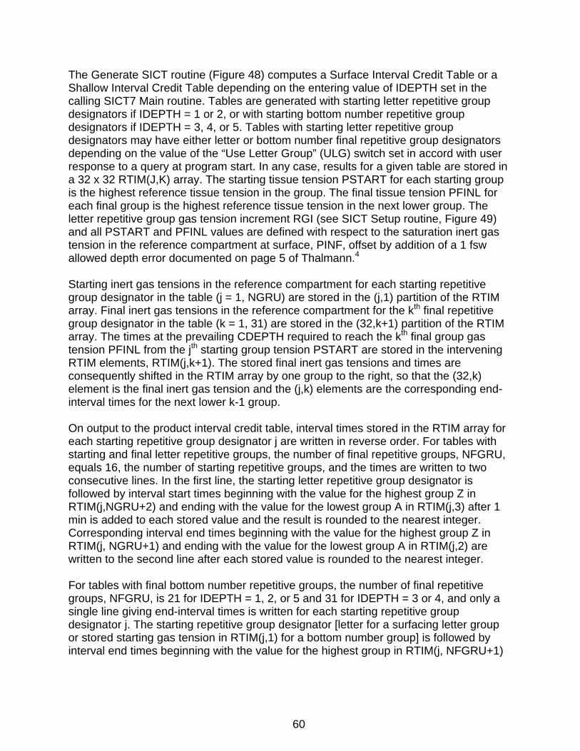
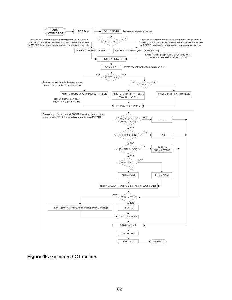
The Generate SICT routine (Figure 48) computes a Surface Interval Credit Table or a Shallow Interval Credit Table depending on the entering value of IDEPTH set in the calling SICT7 Main routine. Tables are generated with starting letter repetitive group designators if IDEPTH = 1 or 2, or with starting bottom number repetitive group designators if IDEPTH = 3, 4, or 5. Tables with starting letter repetitive group designators may have either letter or bottom number final repetitive group designators depending on the value of the “Use Letter Group” (ULG) switch set in accord with user response to a query at program start. In any case, results for a given table are stored in a 32 x 32 RTIM(J,K) array. The starting tissue tension PSTART for each starting group is the highest reference tissue tension in the group. The final tissue tension PFINL for each final group is the highest reference tissue tension in the next lower group. The letter repetitive group gas tension increment RGI (see SICT Setup routine, Figure 49) and all PSTART and PFINL values are defined with respect to the saturation inert gas tension in the reference compartment at surface, PINF, offset by addition of a 1 fsw allowed depth error documented on page 5 of Thalmann.4 Starting inert gas tensions in the reference compartment for each starting repetitive group designator in the table (j = 1, NGRU) are stored in the (j,1) partition of the RTIM array. Final inert gas tensions in the reference compartment for the kth final repetitive group designator in the table (k = 1, 31) are stored in the (32,k+1) partition of the RTIM array. The times at the prevailing CDEPTH required to reach the kth final group gas tension PFINL from the jth starting group tension PSTART are stored in the intervening RTIM elements, RTIM(j,k+1). The stored final inert gas tensions and times are consequently shifted in the RTIM array by one group to the right, so that the (32,k) element is the final inert gas tension and the (j,k) elements are the corresponding end-interval times for the next lower k-1 group. On output to the product interval credit table, interval times stored in the RTIM array for each starting repetitive group designator j are written in reverse order. For tables with starting and final letter repetitive groups, the number of final repetitive groups, NFGRU, equals 16, the number of starting repetitive groups, and the times are written to two consecutive lines. In the first line, the starting letter repetitive group designator is followed by interval start times beginning with the value for the highest group Z in RTIM(j,NGRU+2) and ending with the value for the lowest group A in RTIM(j,3) after 1 min is added to each stored value and the result is rounded to the nearest integer. Corresponding interval end times beginning with the value for the highest group Z in RTIM(j, NGRU+1) and ending with the value for the lowest group A in RTIM(j,2) are written to the second line after each stored value is rounded to the nearest integer. For tables with final bottom number repetitive groups, the number of final repetitive groups, NFGRU, is 21 for IDEPTH = 1, 2, or 5 and 31 for IDEPTH = 3 or 4, and only a single line giving end-interval times is written for each starting repetitive group designator j. The starting repetitive group designator [letter for a surfacing letter group or stored starting gas tension in RTIM(j,1) for a bottom number group] is followed by interval end times beginning with the value for the highest group in RTIM(j, NFGRU+1)
60

and ending with the value for the lowest group in RTIM(j,2) after each stored value is rounded to the nearest integer. After the interval times for all starting groups have been written, the NFGRU final group designators are written in reverse order to the last line in the table. Final bottom number group designators are the stored final gas tensions in the (32,k) [k = 3, NFGRU+2] partition of the RTIM array. The number group designator written in the left-most column, RTIM(32,NFGRU+2), is undefined but taken as the value of INT(RTIM(32,NFGRU+1))+1. Because the stored final gas tension in each (32,k) element of the RTIM array is the final tension for the (k-1) final group, use of the k = 3, NFGRU+2 elements shifts the final number group designators one column to the right in the final table, which aligns each designator with the column that contains the maximum interval end times to which the designator applies.
61
ENTERGenerate SICT DO j =1,NGRU
PSTART = PINF+1.0 + RGI*j
IDEPTH > 2YES
PSTART = INT((MAX( PAN2,PINF )) +1 + j
DO k = 1, 31
ULG
PFINL = PINF+1.0 + RGI*(k–1)PFINL = INT(PINF) +1 + (k–1)( VVal-18: = 24 + k )
IDEPTH > 2
YES
NO
PFINL = INT(MAX( PAN2,PINF )) +1 + (k–1)
PAN2 ≥ PSTART orPFINL < PAN2
PSTART ≤ PFINL
T = ∞
T = 0
PSTART ≤ PVN2TLIN = 0
PLIN = PSTART
PFINL ≥ PVN2
PLIN = PFINLPLIN = PVN2
YES
TLIN = (1/KDSAT)*LN((PLIN–PSTART)/(PAN2–PVN2))
YES
YES
YES
SICT Setup
PFINL < PVN2
TEXP = (1/KDSAT)*LN((PLIN–PAN2)/(PFINL–PAN2)) TEXP = 0
YES
NO
NO
NO
NO
NO
NO
YES
NO
END DO k
END DO j RETURN
RTIM(j,k+1) = T
RTIM(j,1) = PSTART
RTIM(32,k+1) = PFINL
T = TLIN + TEXP
Offgassing table for bottom (number) groups at CDEPTH = 1*DINC, 2*DINC, or 3*DINC shallow interval on GAS specified at CDEPTH during decompression in first profile in *.pcf file.
Offgassing table for surfacing letter groups at CDEPTH = 0*DINC on AIR or at CDEPTH = 1*DINC on GAS specified at CDEPTH during decompression in first profile in *.pcf file.
Final tissue tensions for bottom number groups increase in 1 fsw increments
(Omit starting groups with gas tensions less than when saturated on air at surface)
Iterate end-interval or final group pointer
Iterate starting group pointer
Compute and record time at CDEPTH required to reach final group tension PFINL from starting group tension PSTART
start w/ arterial inert gas tension at CDEPTH + 1fsw
Figure 48. Generate SICT routine.
62
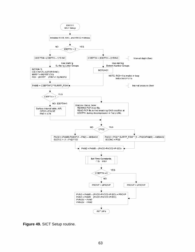
Figure 49. SICT Setup routine.
63
NGRU=16
ENTER SICT Setup
Initialize RTIM, RNT, and RNTD matrices
YES
-{ Interval depth (fsw)
lOX= NINT(LASTOP/DINC) MIREF = M(IREF,IDX)
NOTE: RGI =1 is implicit in loop index increments
RGI = (MIREF- (PINF+1.0))/NGRU
PAMB = CDEPTH*CF*SURFP _FSWI4-----------_j -{ Interval pressure (fsw)
Shallow interval table: REWIND PCF input file. READ PCF file to find breathing GAS specified at CDEPTH during decompression in first profile.
NO YES
PA02 = (PAMB-PH20)*(1 - FN2)- AMBA02 SCONC = (1- FN2)*100
PA02 = P02 * SURFP _FSW * (1 - PH20/PAMB)- AMBA02 SCONC= P02
PAN2 = PAMB- (PA02+PAC02+PH20)
PVN2 = PAMB- (PV02+PVC02+PH20) + PBOVP PAN2 = PAMB- (PA02+PAC02+PH20) PVN2SI = PVN2 PAN2SI = PAN2
RETURN
PBOVP = sPBOVP
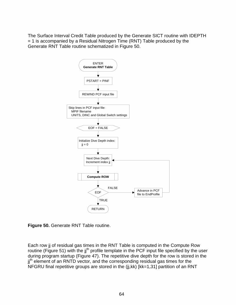
The Surface Interval Credit Table produced by the Generate SICT routine with IDEPTH = 1 is accompanied by a Residual Nitrogen Time (RNT) Table produced by the Generate RNT Table routine schematized in Figure 50.
ENTERGenerate RNT Table
Compute ROW
RETURN
REWIND PCF input file
Next Dive Depth: Increment index jj
EOFFALSE
TRUE
Advance in PCF file to EndProfile
Initialize Dive Depth index:jj = 0
Skip lines in PCF input file:MPIF filenameUNITS, DINC and Global Switch settings
PSTART = PINF
EOF = FALSE
Figure 50. Generate RNT Table routine.
Each row jj of residual gas times in the RNT Table is computed in the Compute Row routine (Figure 51) with the jjth profile template in the PCF input file specified by the user during program startup (Figure 47). The repetitive dive depth for the row is stored in the jjth element of an RNTD vector, and the corresponding residual gas times for the NFGRU final repetitive groups are stored in the (jj,kk) [kk=1,31] partition of an RNT
64
array. For all jj and j, the (jj,kk) elements of the RNT array correspond to the (j,kk+1) elements of the RTIM array in the Generate SICT routine (Figure 48). After the residual gas times for all repetitive dive depths in the PCF input file have been computed, the product RNT table is written under its corresponding interval credit table with times for each depth aligned in a row under the final repetitive group columns to which they apply.
65
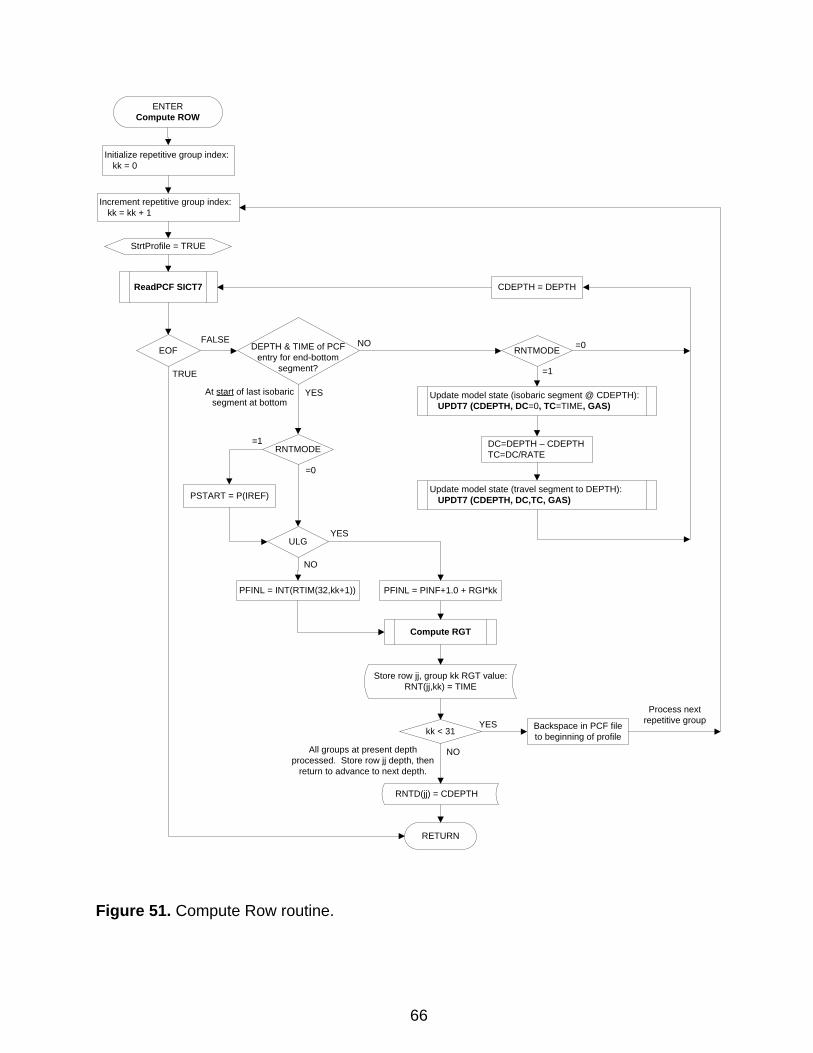
ENTERCompute ROW
DEPTH & TIME of PCF entry for end-bottom
segment?
YES
ReadPCF SICT7
EOF
TRUE
FALSE
Compute RGT
kk < 31 Backspace in PCF file to beginning of profile
NO
RETURN
All groups at present depth processed. Store row jj depth, then
return to advance to next depth.
YES
Process next repetitive group
Initialize repetitive group index:kk = 0
Increment repetitive group index:kk = kk + 1
NO
At start of last isobaric segment at bottom
RNTD(jj) = CDEPTH
Store row jj, group kk RGT value:RNT(jj,kk) = TIME
ULG
PFINL = INT(RTIM(32,kk+1)) PFINL = PINF+1.0 + RGI*kk
YES
NO
DC=DEPTH – CDEPTHTC=DC/RATE
Update model state (isobaric segment @ CDEPTH):UPDT7 (CDEPTH, DC=0, TC=TIME, GAS)
Update model state (travel segment to DEPTH):UPDT7 (CDEPTH, DC,TC, GAS)
RNTMODE
=1
=0
CDEPTH = DEPTH
RNTMODE
=0
=1
PSTART = P(IREF)
StrtProfile = TRUE
Figure 51. Compute Row routine.
66
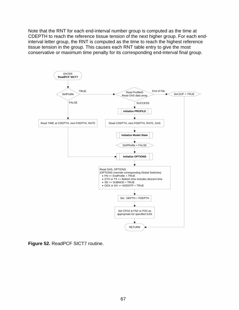
Note that the RNT for each end-interval number group is computed as the time at CDEPTH to reach the reference tissue tension of the next higher group. For each end-interval letter group, the RNT is computed as the time to reach the highest reference tissue tension in the group. This causes each RNT table entry to give the most conservative or maximum time penalty for its corresponding end-interval final group.
Read TIME at CDEPTH, next FDEPTH, RATE
Initialize OPTIONS
Read GAS, OPTIONS(OPTIONS override corresponding Global Switches)
FN == EndProfile = TRUEGTX or TX == Bottom time includes descent timeSD == SUBNOD = TRUEGDX or DX == NODSTP = TRUE
Initialize PROFILE
Read CDEPTH, next FDEPTH, RATE, GAS
Read ProfileIDRead GAS data array
SUCCESS
End of File
Initialize Model State
StrtProfile
FALSE
TRUESet EOF = TRUE
Set : DEPTH = FDEPTH
ENTERReadPCF SICT7
RETURN
Set CPO2 & FN2 or PO2 as appropriate for specified GAS
StrtPRofile = FALSE
Figure 52. ReadPCF SICT7 routine.
67
5. References
1. E. D. Thalmann, Computer Algorithms Used in Computing the MK 15/16 Constant 0.7 ATA Oxygen Partial Pressure Decompression Tables, NEDU TR 1-83, Navy Experimental Diving Unit, Panama City, FL, Jan 1983.
2. E. D. Thalmann, Erratum NEDU Report 1-83: Computer Algorithms Used in Computing the MK 15/16 Constant 0.7 ATA Oxygen Partial Pressure Decompression Tables, Navy Experimental Diving Unit, Panama City, FL, Mar 1983.
3. E. D. Thalmann, Phase II Testing of Decompression Algorithms for Use in the U.S. Navy Underwater Decompression Computer, NEDU TR 1-84, Navy Experimental Diving Unit, Panama City, FL, Jan 1984.
4. E. D. Thalmann, Repetitive/Multi-Level Dive Procedures and Tables for Constant 0.7 ATA Oxygen Partial Pressure in Nitrogen Diving, NEDU TR 9-85, Navy Experimental Diving Unit, Panama City, FL, Sep 1985.
5. E. D. Thalmann, Source Listings for Programs TBLP7R and SICT7, NEDU TM 85-12, Navy Experimental Diving Unit, Panama City, FL, Sep 1985.
6. T. M. Johnson, W. A. Gerth, and D. G. Southerland, 1.3 ATA PO2 N2-O2 Decompression Table Validation, NEDU TR 9-00, Navy Experimental Diving Unit, Panama City, FL, Sep 2000.
7. T. M. Johnson and W. A. Gerth, 1.3 ATA PO2-in-He Decompression Tables for MK 16 MOD 1 Diving: Summary Report and Operational Guidance, NEDU TR 14-01, Navy Experimental Diving Unit, Panama City, FL, Oct 2001.
8. W. A. Gerth and T. M. Johnson, Development and Validation of 1.3 ATA PO2-in-He Decompression Tables for the MK 16 MOD 1 UBA, NEDU TR 02-10, Navy Experimental Diving Unit, Panama City, FL, Aug 2002.
9. W. A. Gerth, Oxygen-Accelerated Decompression of Submarine Rescue Diving Recompression System (SRDRS) Operators and Tenders, NEDU TR 05-04, Navy Experimental Diving Unit, Panama City, FL, Apr 2005.
10. Commander, Naval Sea Systems Command, U.S. Navy Diving Manual, Revision 6, Publication SS521-AG-PRO-010 (Arlington, VA: NAVSEA, 2008).
11. W. A. Gerth and D. J. Doolette, Schedules in the Integrated Air Decompression Table of U.S. Navy Diving Manual, Revision 6: Computation and Estimated Risks of Decompression Sickness, NEDU TR 09-05, Navy Experimental Diving Unit, Panama City, FL, Jun 2009.
68
69
12. W. A. Gerth, “Probabilistic Models of Decompression Sickness During Flying After Diving: Motivation for Mechanism,” in P. K. Weathersby and W. A. Gerth, eds., Survival Analysis and Maximum Likelihood Techniques as Applied to Physiological Modeling (Kensington, MD: Undersea and Hyperbaric Medical Society, 2002), pp. 118–136.
13. H. D. Van Liew, “Pressure Conversion Table,” Undersea Biomedical Research, Vol. 17, No. 4 (1990), pp. 273–274.
14. J. Clarke, K. Russell, and L. Crepeau, MK 16 Canister Limits for SDV Operations, NEDU TR 2-93 (Confidential), Navy Experimental Diving Unit, Panama City, FL, June 1993.
15. R. D. Workman, Calculation of Decompression Schedules for Nitrogen-Oxygen and Helium-Oxygen Dives, NEDU TR 6-65, Navy Experimental Diving Unit, 1965.
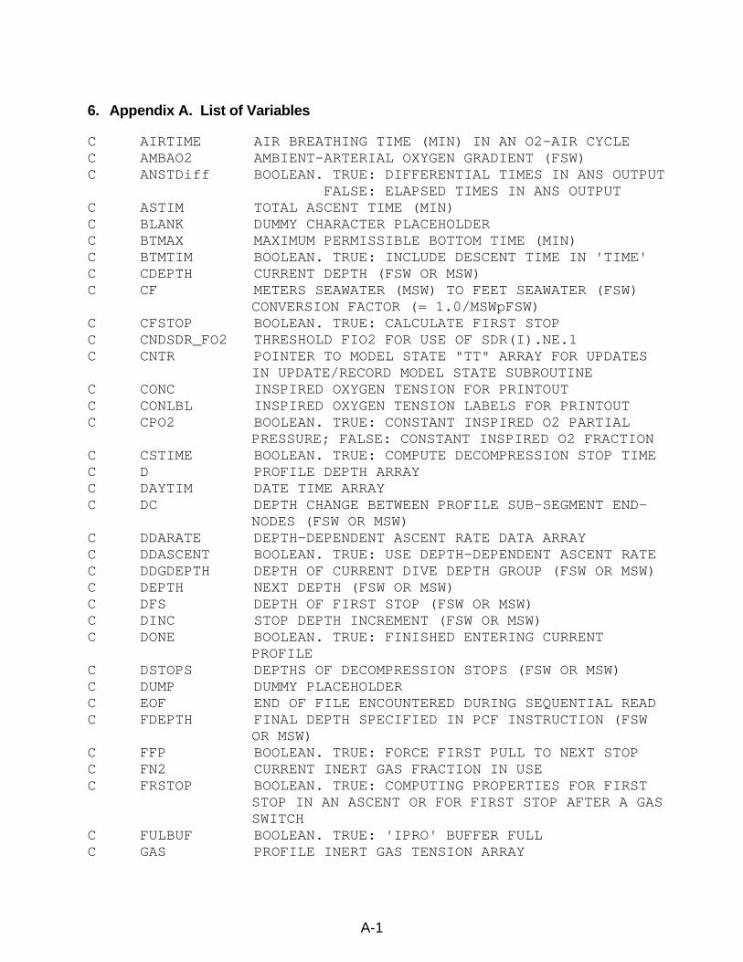
6. Appendix A. List of Variables
C AIRTIME AIR BREATHING TIME (MIN) IN AN O2-AIR CYCLE C AMBAO2 AMBIENT-ARTERIAL OXYGEN GRADIENT (FSW) C ANSTDiff BOOLEAN. TRUE: DIFFERENTIAL TIMES IN ANS OUTPUT FALSE: ELAPSED TIMES IN ANS OUTPUT C ASTIM TOTAL ASCENT TIME (MIN) C BLANK DUMMY CHARACTER PLACEHOLDER C BTMAX MAXIMUM PERMISSIBLE BOTTOM TIME (MIN) C BTMTIM BOOLEAN. TRUE: INCLUDE DESCENT TIME IN 'TIME' C CDEPTH CURRENT DEPTH (FSW OR MSW) C CF METERS SEAWATER (MSW) TO FEET SEAWATER (FSW)
CONVERSION FACTOR (= 1.0/MSWpFSW) C CFSTOP BOOLEAN. TRUE: CALCULATE FIRST STOP C CNDSDR_FO2 THRESHOLD FIO2 FOR USE OF SDR(I).NE.1 C CNTR POINTER TO MODEL STATE "TT" ARRAY FOR UPDATES
IN UPDATE/RECORD MODEL STATE SUBROUTINE C CONC INSPIRED OXYGEN TENSION FOR PRINTOUT C CONLBL INSPIRED OXYGEN TENSION LABELS FOR PRINTOUT C CPO2 BOOLEAN. TRUE: CONSTANT INSPIRED O2 PARTIAL
PRESSURE; FALSE: CONSTANT INSPIRED O2 FRACTION C CSTIME BOOLEAN. TRUE: COMPUTE DECOMPRESSION STOP TIME C D PROFILE DEPTH ARRAY C DAYTIM DATE TIME ARRAY C DC DEPTH CHANGE BETWEEN PROFILE SUB-SEGMENT END-
NODES (FSW OR MSW) C DDARATE DEPTH-DEPENDENT ASCENT RATE DATA ARRAY C DDASCENT BOOLEAN. TRUE: USE DEPTH-DEPENDENT ASCENT RATE C DDGDEPTH DEPTH OF CURRENT DIVE DEPTH GROUP (FSW OR MSW) C DEPTH NEXT DEPTH (FSW OR MSW) C DFS DEPTH OF FIRST STOP (FSW OR MSW) C DINC STOP DEPTH INCREMENT (FSW OR MSW) C DONE BOOLEAN. TRUE: FINISHED ENTERING CURRENT
PROFILE C DSTOPS DEPTHS OF DECOMPRESSION STOPS (FSW OR MSW) C DUMP DUMMY PLACEHOLDER C EOF END OF FILE ENCOUNTERED DURING SEQUENTIAL READ C FDEPTH FINAL DEPTH SPECIFIED IN PCF INSTRUCTION (FSW
OR MSW) C FFP BOOLEAN. TRUE: FORCE FIRST PULL TO NEXT STOP C FN2 CURRENT INERT GAS FRACTION IN USE C FRSTOP BOOLEAN. TRUE: COMPUTING PROPERTIES FOR FIRST
STOP IN AN ASCENT OR FOR FIRST STOP AFTER A GAS SWITCH
C FULBUF BOOLEAN. TRUE: 'IPRO' BUFFER FULL C GAS PROFILE INERT GAS TENSION ARRAY
A-1
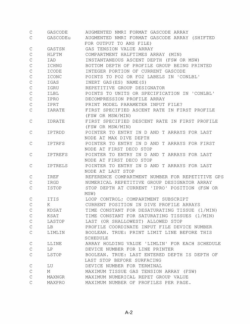
C GASCODE AUGMENTED NMRI FORMAT GASCODE ARRAY C GASCODEu AUGMENTED NMRI FORMAT GASCODE ARRAY (SHIFTED
FOR OUTPUT TO ANS FILE) C GASTSN GAS TENSION VALUE ARRAY C HLFTM COMPARTMENT HALFTIMES ARRAY (MIN) C IAD INSTANTANEOUS ASCENT DEPTH (FSW OR MSW) C ICHNG BOTTOM DEPTH OF PROFILE GROUP BEING PRINTED C ICODE INTEGER PORTION OF CURRENT GASCODE C ICONC POINTS TO PO2 OR FO2 LABELS IN 'CONLBL' C IGAS INERT GAS(ES) NAME(S) C IGRU REPETITIVE GROUP DESIGNATOR C ILBL POINTS TO UNITS OR SPECIFICATION IN 'CONLBL' C IPRO DECOMPRESSION PROFILE ARRAY C IPRT PRINT MODEL PARAMETER INPUT FILE? C IARATE FIRST SPECIFIED ASCENT RATE IN FIRST PROFILE
(FSW OR MSW/MIN) C IDRATE FIRST SPECIFIED DESCENT RATE IN FIRST PROFILE
(FSW OR MSW/MIN) C IPTRDD POINTER TO ENTRY IN D AND T ARRAYS FOR LAST
NODE AT MAX DIVE DEPTH C IPTRFS POINTER TO ENTRY IN D AND T ARRAYS FOR FIRST
NODE AT FIRST DECO STOP C IPTREFS POINTER TO ENTRY IN D AND T ARRAYS FOR LAST
NODE AT FIRST DECO STOP C IPTRELS POINTER TO ENTRY IN D AND T ARRAYS FOR LAST
NODE AT LAST STOP C IREF REFERENCE COMPARTMENT NUMBER FOR REPETITIVE GPS C IRGD NUMERICAL REPETITIVE GROUP DESIGNATOR ARRAY C ISTOP STOP DEPTH AT CURRENT 'IPRO' POSITION (FSW OR
MSW) C ITIS LOOP CONTROL; COMPARTMENT SUBSCRIPT C K CURRENT POSITION IN DIVE PROFILE ARRAYS C KDSAT TIME CONSTANT FOR DESATURATING TISSUE (1/MIN) C KSAT TIME CONSTANT FOR SATURATING TISSUES (1/MIN) C LASTOP LAST (OR SHALLOWEST) ALLOWED STOP C LB PROFILE COORDINATE INPUT FILE DEVICE NUMBER C LIMLIN BOOLEAN. TRUE: PRINT LIMIT LINE BEFORE THIS
SCHEDULE C LLINE ARRAY HOLDING VALUE 'LIMLIN' FOR EACH SCHEDULE C LP DEVICE NUMBER FOR LINE PRINTER C LSTOP BOOLEAN. TRUE: LAST ENTERED DEPTH IS DEPTH OF
LAST STOP BEFORE SURFACING C LU DEVICE NUMBER FOR TERMINAL C M MAXIMUM TISSUE GAS TENSION ARRAY (FSW) C MAXNGR MAXIMUM NUMERICAL REPET GROUP VALUE C MAXPRO MAXIMUM NUMBER OF PROFILES PER PAGE.
A-2
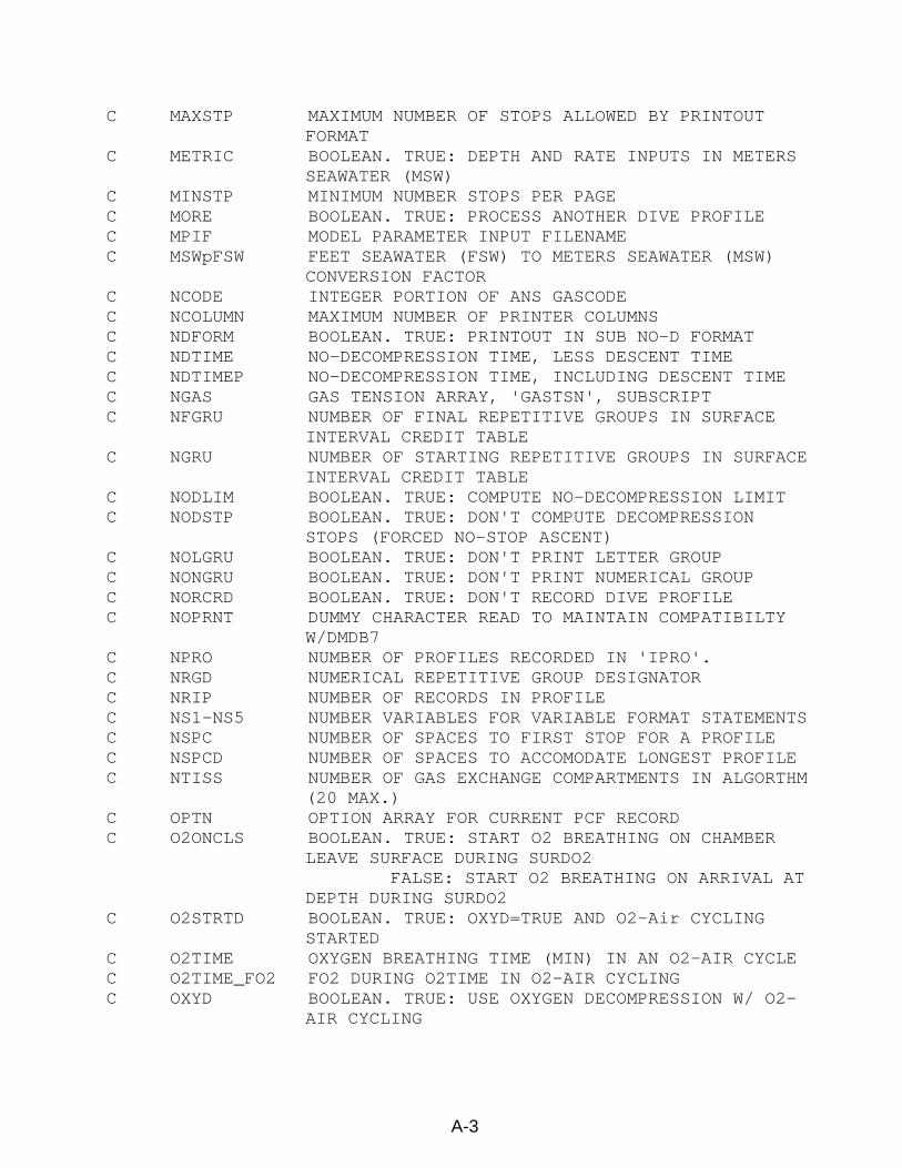
C MAXSTP MAXIMUM NUMBER OF STOPS ALLOWED BY PRINTOUT FORMAT
C METRIC BOOLEAN. TRUE: DEPTH AND RATE INPUTS IN METERS SEAWATER (MSW)
C MINSTP MINIMUM NUMBER STOPS PER PAGE C MORE BOOLEAN. TRUE: PROCESS ANOTHER DIVE PROFILE C MPIF MODEL PARAMETER INPUT FILENAME C MSWpFSW FEET SEAWATER (FSW) TO METERS SEAWATER (MSW)
CONVERSION FACTOR C NCODE INTEGER PORTION OF ANS GASCODE C NCOLUMN MAXIMUM NUMBER OF PRINTER COLUMNS C NDFORM BOOLEAN. TRUE: PRINTOUT IN SUB NO-D FORMAT C NDTIME NO-DECOMPRESSION TIME, LESS DESCENT TIME C NDTIMEP NO-DECOMPRESSION TIME, INCLUDING DESCENT TIME C NGAS GAS TENSION ARRAY, 'GASTSN', SUBSCRIPT C NFGRU NUMBER OF FINAL REPETITIVE GROUPS IN SURFACE
INTERVAL CREDIT TABLE C NGRU NUMBER OF STARTING REPETITIVE GROUPS IN SURFACE
INTERVAL CREDIT TABLE C NODLIM BOOLEAN. TRUE: COMPUTE NO-DECOMPRESSION LIMIT C NODSTP BOOLEAN. TRUE: DON'T COMPUTE DECOMPRESSION
STOPS (FORCED NO-STOP ASCENT) C NOLGRU BOOLEAN. TRUE: DON'T PRINT LETTER GROUP C NONGRU BOOLEAN. TRUE: DON'T PRINT NUMERICAL GROUP C NORCRD BOOLEAN. TRUE: DON'T RECORD DIVE PROFILE C NOPRNT DUMMY CHARACTER READ TO MAINTAIN COMPATIBILTY
W/DMDB7 C NPRO NUMBER OF PROFILES RECORDED IN 'IPRO'. C NRGD NUMERICAL REPETITIVE GROUP DESIGNATOR C NRIP NUMBER OF RECORDS IN PROFILE C NS1-NS5 NUMBER VARIABLES FOR VARIABLE FORMAT STATEMENTS C NSPC NUMBER OF SPACES TO FIRST STOP FOR A PROFILE C NSPCD NUMBER OF SPACES TO ACCOMODATE LONGEST PROFILE C NTISS NUMBER OF GAS EXCHANGE COMPARTMENTS IN ALGORTHM
(20 MAX.) C OPTN OPTION ARRAY FOR CURRENT PCF RECORD C O2ONCLS BOOLEAN. TRUE: START O2 BREATHING ON CHAMBER
LEAVE SURFACE DURING SURDO2 FALSE: START O2 BREATHING ON ARRIVAL AT
DEPTH DURING SURDO2 C O2STRTD BOOLEAN. TRUE: OXYD=TRUE AND O2-Air CYCLING
STARTED C O2TIME OXYGEN BREATHING TIME (MIN) IN AN O2-AIR CYCLE C O2TIME_FO2 FO2 DURING O2TIME IN O2-AIR CYCLING C OXYD BOOLEAN. TRUE: USE OXYGEN DECOMPRESSION W/ O2-
AIR CYCLING
A-3
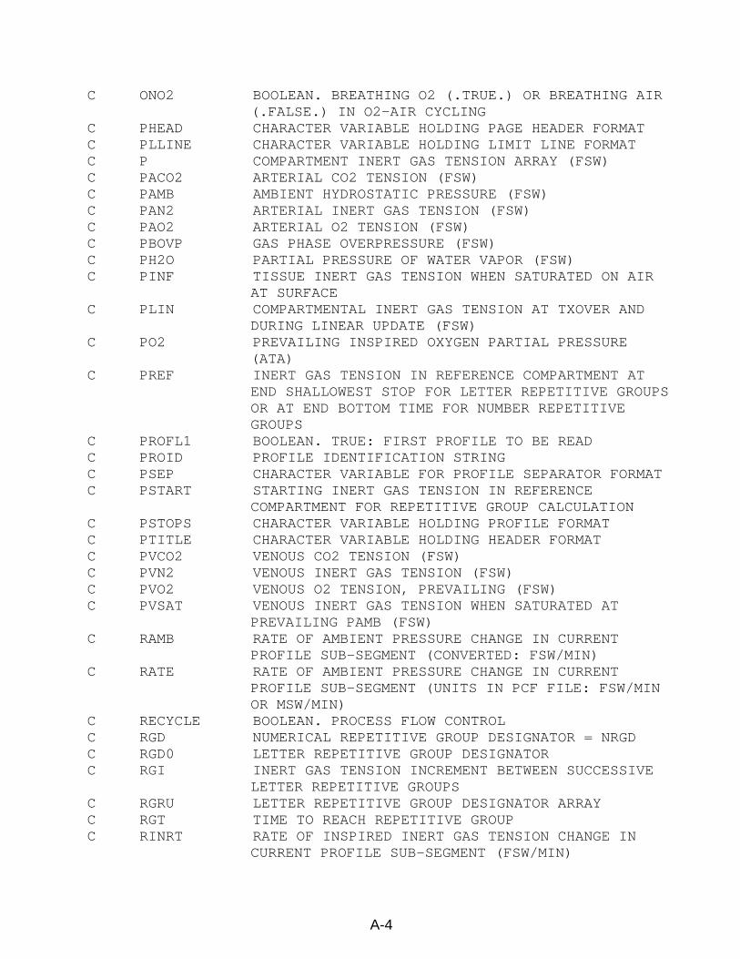
C ONO2 BOOLEAN. BREATHING O2 (.TRUE.) OR BREATHING AIR (.FALSE.) IN O2-AIR CYCLING
C PHEAD CHARACTER VARIABLE HOLDING PAGE HEADER FORMAT C PLLINE CHARACTER VARIABLE HOLDING LIMIT LINE FORMAT C P COMPARTMENT INERT GAS TENSION ARRAY (FSW) C PACO2 ARTERIAL CO2 TENSION (FSW) C PAMB AMBIENT HYDROSTATIC PRESSURE (FSW) C PAN2 ARTERIAL INERT GAS TENSION (FSW) C PAO2 ARTERIAL O2 TENSION (FSW) C PBOVP GAS PHASE OVERPRESSURE (FSW) C PH2O PARTIAL PRESSURE OF WATER VAPOR (FSW) C PINF TISSUE INERT GAS TENSION WHEN SATURATED ON AIR
AT SURFACE C PLIN COMPARTMENTAL INERT GAS TENSION AT TXOVER AND
DURING LINEAR UPDATE (FSW) C PO2 PREVAILING INSPIRED OXYGEN PARTIAL PRESSURE
(ATA) C PREF INERT GAS TENSION IN REFERENCE COMPARTMENT AT
END SHALLOWEST STOP FOR LETTER REPETITIVE GROUPS OR AT END BOTTOM TIME FOR NUMBER REPETITIVE GROUPS
C PROFL1 BOOLEAN. TRUE: FIRST PROFILE TO BE READ C PROID PROFILE IDENTIFICATION STRING C PSEP CHARACTER VARIABLE FOR PROFILE SEPARATOR FORMAT C PSTART STARTING INERT GAS TENSION IN REFERENCE
COMPARTMENT FOR REPETITIVE GROUP CALCULATION C PSTOPS CHARACTER VARIABLE HOLDING PROFILE FORMAT C PTITLE CHARACTER VARIABLE HOLDING HEADER FORMAT C PVCO2 VENOUS CO2 TENSION (FSW) C PVN2 VENOUS INERT GAS TENSION (FSW) C PVO2 VENOUS O2 TENSION, PREVAILING (FSW) C PVSAT VENOUS INERT GAS TENSION WHEN SATURATED AT
PREVAILING PAMB (FSW) C RAMB RATE OF AMBIENT PRESSURE CHANGE IN CURRENT
PROFILE SUB-SEGMENT (CONVERTED: FSW/MIN) C RATE RATE OF AMBIENT PRESSURE CHANGE IN CURRENT
PROFILE SUB-SEGMENT (UNITS IN PCF FILE: FSW/MIN OR MSW/MIN)
C RECYCLE BOOLEAN. PROCESS FLOW CONTROL C RGD NUMERICAL REPETITIVE GROUP DESIGNATOR = NRGD C RGD0 LETTER REPETITIVE GROUP DESIGNATOR C RGI INERT GAS TENSION INCREMENT BETWEEN SUCCESSIVE
LETTER REPETITIVE GROUPS C RGRU LETTER REPETITIVE GROUP DESIGNATOR ARRAY C RGT TIME TO REACH REPETITIVE GROUP C RINRT RATE OF INSPIRED INERT GAS TENSION CHANGE IN
CURRENT PROFILE SUB-SEGMENT (FSW/MIN)
A-4
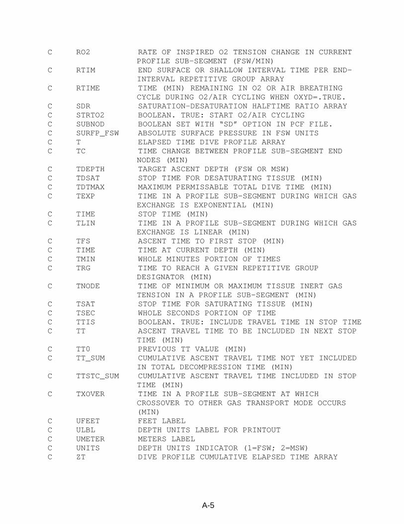
A-5
C RO2 RATE OF INSPIRED O2 TENSION CHANGE IN CURRENT PROFILE SUB-SEGMENT (FSW/MIN)
C RTIM END SURFACE OR SHALLOW INTERVAL TIME PER END-INTERVAL REPETITIVE GROUP ARRAY
C RTIME TIME (MIN) REMAINING IN O2 OR AIR BREATHING CYCLE DURING O2/AIR CYCLING WHEN OXYD=.TRUE.
C SDR SATURATION-DESATURATION HALFTIME RATIO ARRAY C STRTO2 BOOLEAN. TRUE: START O2/AIR CYCLING C SUBNOD BOOLEAN SET WITH “SD” OPTION IN PCF FILE. C SURFP_FSW ABSOLUTE SURFACE PRESSURE IN FSW UNITS C T ELAPSED TIME DIVE PROFILE ARRAY C TC TIME CHANGE BETWEEN PROFILE SUB-SEGMENT END
NODES (MIN) C TDEPTH TARGET ASCENT DEPTH (FSW OR MSW) C TDSAT STOP TIME FOR DESATURATING TISSUE (MIN) C TDTMAX MAXIMUM PERMISSABLE TOTAL DIVE TIME (MIN) C TEXP TIME IN A PROFILE SUB-SEGMENT DURING WHICH GAS
EXCHANGE IS EXPONENTIAL (MIN) C TIME STOP TIME (MIN) C TLIN TIME IN A PROFILE SUB-SEGMENT DURING WHICH GAS
EXCHANGE IS LINEAR (MIN) C TFS ASCENT TIME TO FIRST STOP (MIN) C TIME TIME AT CURRENT DEPTH (MIN) C TMIN WHOLE MINUTES PORTION OF TIMES C TRG TIME TO REACH A GIVEN REPETITIVE GROUP
DESIGNATOR (MIN) C TNODE TIME OF MINIMUM OR MAXIMUM TISSUE INERT GAS
TENSION IN A PROFILE SUB-SEGMENT (MIN) C TSAT STOP TIME FOR SATURATING TISSUE (MIN) C TSEC WHOLE SECONDS PORTION OF TIME C TTIS BOOLEAN. TRUE: INCLUDE TRAVEL TIME IN STOP TIME C TT ASCENT TRAVEL TIME TO BE INCLUDED IN NEXT STOP
TIME (MIN) C TT0 PREVIOUS TT VALUE (MIN) C TT_SUM CUMULATIVE ASCENT TRAVEL TIME NOT YET INCLUDED
IN TOTAL DECOMPRESSION TIME (MIN) C TTSTC_SUM CUMULATIVE ASCENT TRAVEL TIME INCLUDED IN STOP
TIME (MIN) C TXOVER TIME IN A PROFILE SUB-SEGMENT AT WHICH
CROSSOVER TO OTHER GAS TRANSPORT MODE OCCURS (MIN)
C UFEET FEET LABEL C ULBL DEPTH UNITS LABEL FOR PRINTOUT C UMETER METERS LABEL C UNITS DEPTH UNITS INDICATOR (1=FSW; 2=MSW) C ZT DIVE PROFILE CUMULATIVE ELAPSED TIME ARRAY
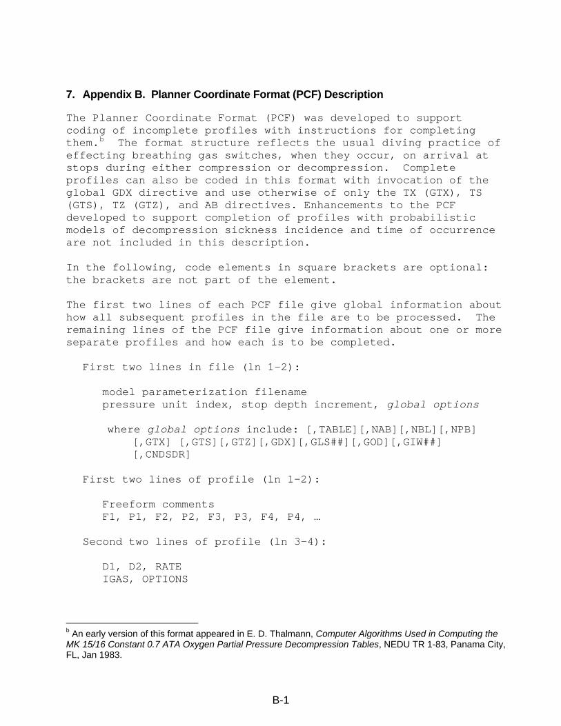
7. Appendix B. Planner Coordinate Format (PCF) Description
The Planner Coordinate Format (PCF) was developed to support coding of incomplete profiles with instructions for completing them.b The format structure reflects the usual diving practice of effecting breathing gas switches, when they occur, on arrival at stops during either compression or decompression. Complete profiles can also be coded in this format with invocation of the global GDX directive and use otherwise of only the TX (GTX), TS (GTS), TZ (GTZ), and AB directives. Enhancements to the PCF developed to support completion of profiles with probabilistic models of decompression sickness incidence and time of occurrence are not included in this description. In the following, code elements in square brackets are optional: the brackets are not part of the element. The first two lines of each PCF file give global information about how all subsequent profiles in the file are to be processed. The remaining lines of the PCF file give information about one or more separate profiles and how each is to be completed.
First two lines in file (ln 1-2): model parameterization filename pressure unit index, stop depth increment, global options where global options include: [,TABLE][,NAB][,NBL][,NPB]
[,GTX] [,GTS][,GTZ][,GDX][,GLS##][,GOD][,GIW##] [,CNDSDR]
First two lines of profile (ln 1-2): Freeform comments F1, P1, F2, P2, F3, P3, F4, P4, … Second two lines of profile (ln 3-4): D1, D2, RATE IGAS, OPTIONS
b An early version of this format appeared in E. D. Thalmann, Computer Algorithms Used in Computing the MK 15/16 Constant 0.7 ATA Oxygen Partial Pressure Decompression Tables, NEDU TR 1-83, Panama City, FL, Jan 1983.
B-1

These profile lines specify the initial conditions for the profile and the first stage in the profile. By default, the profile is started from initial saturation on air at the pressure D1 specified in this record, with reference surface pressure at sea level. The first stage in the profile is then to travel to D2 on IGAS at the specified RATE.
Each remaining pair of lines in the profile — (ln 5-6), (ln 7-8), etc. — contains entries in the following format: TIME, D2, RATE IGAS, OPTIONS
The entries describe the PRESSURE, respired gas, and TIME properties — or provide information for calculation of these properties — between three nodes in a dive profile as schematized in Figure B.1:
D1 (=D2 from node 2 of previous record or initial conditions if present record is the first in the profile)
Time
Pressure
D2
Node # : 0* 1 2
TIME IGAS
RATE (as specified)
* Node 0 is node 2 of previous record or as defined by initial conditions if the present record is the first in the profile.
Figure B.1. Schematization of nodes (filled circles) generated from a two-line *.pcf record. Slashed lines indicate that some information about pressure, respired gas, and time in these internodal regions may be calculated in accord with instructions in the OPTIONS list. Such calculation may result in insertion of one or more additional nodes between the three illustrated nodes.
B-2
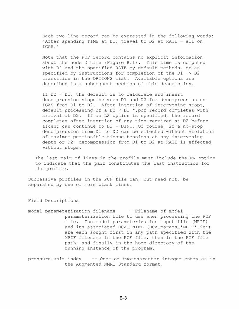
Each two-line record can be expressed in the following words: "After spending TIME at D1, travel to D2 at RATE — all on IGAS." Note that the PCF record contains no explicit information about the node 2 time (Figure B.1). This time is computed with D2 and the specified RATE by default methods, or as specified by instructions for completion of the D1 -> D2 transition in the OPTIONS list. Available options are described in a subsequent section of this description. If D2 < D1, the default is to calculate and insert decompression stops between D1 and D2 for decompression on IGAS from D1 to D2. After insertion of intervening stops, default processing of a D2 < D1 *.pcf record completes with arrival at D2. If an LS option is specified, the record completes after insertion of any time required at D2 before ascent can continue to D2 – DINC. Of course, if a no-stop decompression from D1 to D2 can be effected without violation of maximum permissible tissue tensions at any intervening depth or D2, decompression from D1 to D2 at RATE is effected without stops.
The last pair of lines in the profile must include the FN option to indicate that the pair constitutes the last instruction for the profile.
Successive profiles in the PCF file can, but need not, be separated by one or more blank lines. Field Descriptions model parameterization filename -- Filename of model
parameterization file to use when processing the PCF file. The model parameterization input file (MPIF) and its associated DCA_INIFL (DCA_params_*MPIF*.ini) are each sought first in any path specified with the MPIF filename in the PCF file, then in the PCF file path, and finally in the home directory of the running instance of the program.
pressure unit index -- One- or two-character integer entry as in
the Augmented NMRI Standard format.
B-3
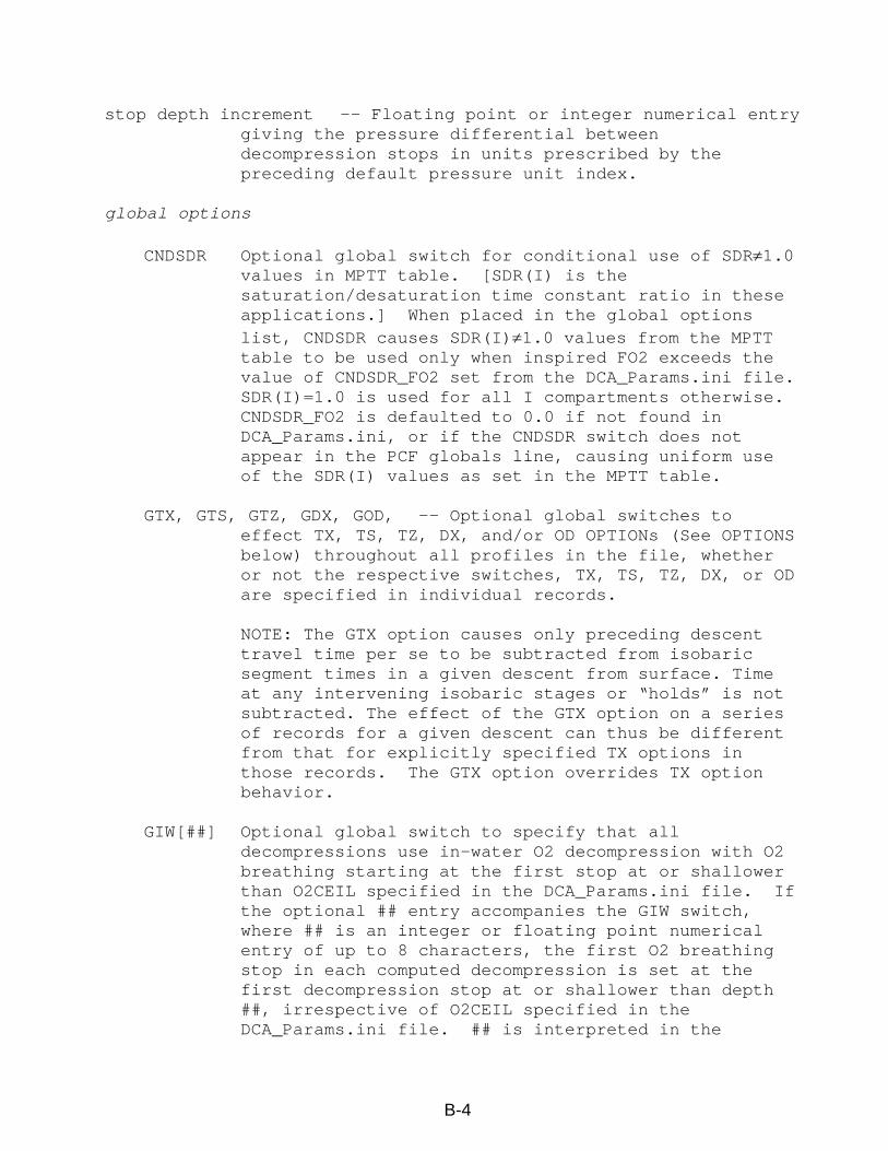
stop depth increment -- Floating point or integer numerical entry giving the pressure differential between decompression stops in units prescribed by the preceding default pressure unit index.
global options
CNDSDR Optional global switch for conditional use of SDR≠1.0
values in MPTT table. [SDR(I) is the saturation/desaturation time constant ratio in these applications.] When placed in the global options list, CNDSDR causes SDR(I)≠1.0 values from the MPTT table to be used only when inspired FO2 exceeds the value of CNDSDR_FO2 set from the DCA_Params.ini file. SDR(I)=1.0 is used for all I compartments otherwise. CNDSDR_FO2 is defaulted to 0.0 if not found in DCA_Params.ini, or if the CNDSDR switch does not appear in the PCF globals line, causing uniform use of the SDR(I) values as set in the MPTT table.
GTX, GTS, GTZ, GDX, GOD, -- Optional global switches to
effect TX, TS, TZ, DX, and/or OD OPTIONs (See OPTIONS below) throughout all profiles in the file, whether or not the respective switches, TX, TS, TZ, DX, or OD are specified in individual records.
NOTE: The GTX option causes only preceding descent
travel time per se to be subtracted from isobaric segment times in a given descent from surface. Time at any intervening isobaric stages or “holds” is not subtracted. The effect of the GTX option on a series of records for a given descent can thus be different from that for explicitly specified TX options in those records. The GTX option overrides TX option behavior.
GIW[##] Optional global switch to specify that all
decompressions use in-water O2 decompression with O2 breathing starting at the first stop at or shallower than O2CEIL specified in the DCA_Params.ini file. If the optional ## entry accompanies the GIW switch, where ## is an integer or floating point numerical entry of up to 8 characters, the first O2 breathing stop in each computed decompression is set at the first decompression stop at or shallower than depth ##, irrespective of O2CEIL specified in the DCA_Params.ini file. ## is interpreted in the
B-4
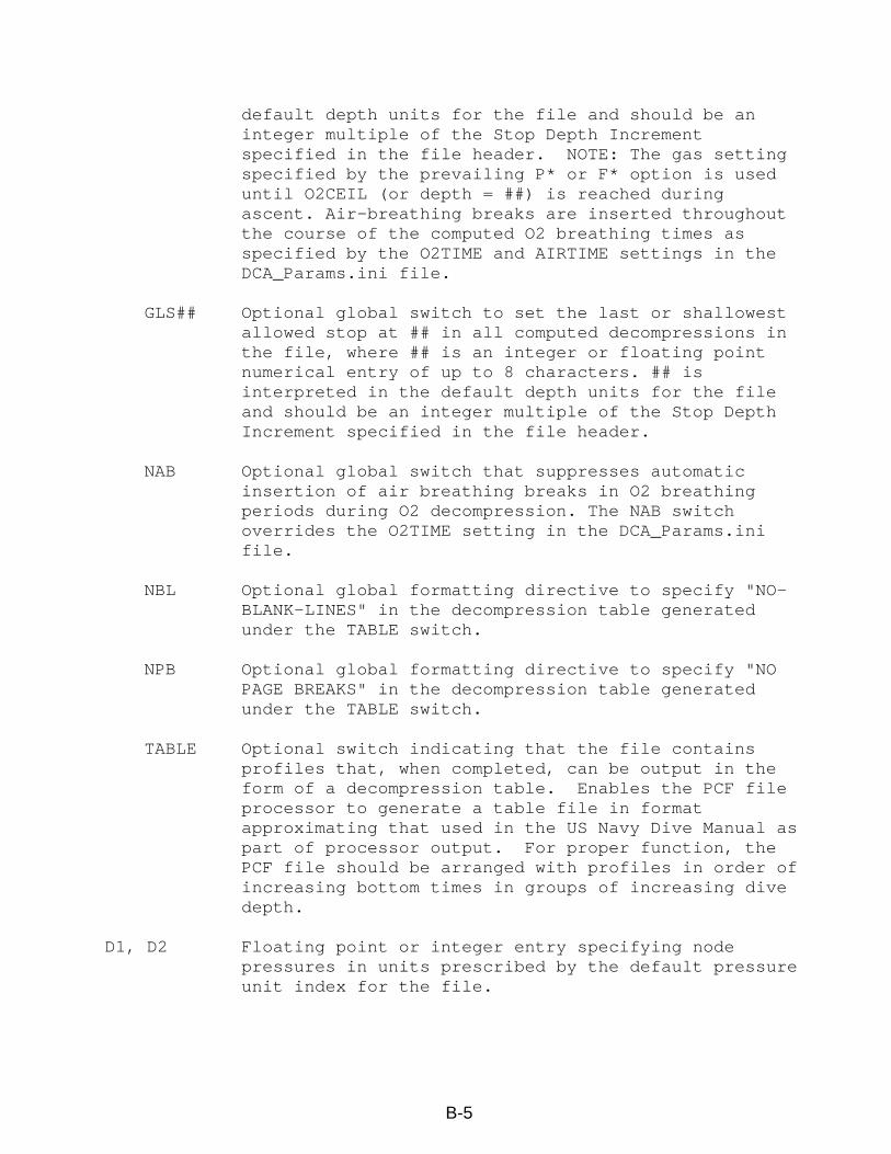
default depth units for the file and should be an integer multiple of the Stop Depth Increment specified in the file header. NOTE: The gas setting specified by the prevailing P* or F* option is used until O2CEIL (or depth = ##) is reached during ascent. Air-breathing breaks are inserted throughout the course of the computed O2 breathing times as specified by the O2TIME and AIRTIME settings in the DCA_Params.ini file.
GLS## Optional global switch to set the last or shallowest
allowed stop at ## in all computed decompressions in the file, where ## is an integer or floating point numerical entry of up to 8 characters. ## is interpreted in the default depth units for the file and should be an integer multiple of the Stop Depth Increment specified in the file header.
NAB Optional global switch that suppresses automatic
insertion of air breathing breaks in O2 breathing periods during O2 decompression. The NAB switch overrides the O2TIME setting in the DCA_Params.ini file.
NBL Optional global formatting directive to specify "NO-
BLANK-LINES" in the decompression table generated under the TABLE switch.
NPB Optional global formatting directive to specify "NO
PAGE BREAKS" in the decompression table generated under the TABLE switch.
TABLE Optional switch indicating that the file contains
profiles that, when completed, can be output in the form of a decompression table. Enables the PCF file processor to generate a table file in format approximating that used in the US Navy Dive Manual as part of processor output. For proper function, the PCF file should be arranged with profiles in order of increasing bottom times in groups of increasing dive depth.
D1, D2 Floating point or integer entry specifying node
pressures in units prescribed by the default pressure unit index for the file.
B-5
F1, F2, …, Fn Floating point numerical entry for the nth inert gas fraction (or Gas Code) breathed in the profile.
if < 1.0, Fn = N2 fraction in nth respired N2-O2 mix, dry.
if ≥ 1.0, Fn = Augmented NMRI Standard format Gas Code for nth gas breathed in the profile. Note that this is the only means by which respired gases other than N2-O2 mixes can be coded.
IGAS Alpha “F” or “P” followed by an integer pointing to a
gas description in the 2nd line of the PCF file. Entry indicates the gas mix breathed during the stages described in the current profile record. E.g., “F3” indicates that the third gas fraction (or Gas Code) given in line 2 is breathed during the current profile stages.
OPTIONS Series of upper case alpha and numeric entries
indicating action to take in processing the present profile record. Options may, but need not, be separated by commas or spaces. More than one option may be specified, as appropriate, in any order.
P1, P2, …, Pn Floating point numerical entry for the nth O2
partial pressure breathed in the profile, wet (after adjustment for water vapor pressure).
RATE Floating point or integer numerical entry specifying
the rate, in UNITS/min, for the D1 to D2 transition (compression or decompression) specified in the record. The UNITS used to interpret the entry are those used to interpret the D2 entry in the record. If D2 = D1, the RATE entry has no effect.
TIME Floating point or integer entry specifying duration
of residence at D1 in minutes. Options AB Insert air breaks into residence on IGAS (FI_2) at D1
according to O2/AIR cycling specified in the DCA_Params.ini file. This option is exercised only on stages for which D1 > Surface Pressure. If AB is specified in a record for which a decompression is computed, O2/AIR cycling is continued through the decompression with an AIRTIME minute air break after each O2TIME minutes on IGAS, unless an OD
B-6
option accompanies the AB option. In the latter cases, the OD option causes gas with O2TIME_FO2 specified in the DCA_Params.ini file to be breathed during each O2TIME period during the decompression, but not during preceding residence at D1.
DX Decompress from D1 -> D2 without staging. The DX option
overrides default decompression optimization and effects no-stop decompression from D1 to D2.
FN (or FL) Last PCF record for profile. IW Invokes the OD option with specific settings for in-water O2
decompression; O2 at O2TIME_FO2 starting at O2CEIL specified in DCA_Params.ini file. If the NAB global option has not been set at the beginning of the file, air-breathing breaks are inserted throughout the course of the computed O2 breathing time of the decompression as specified by the O2TIME and AIRTIME settings in the DCA_Params.ini file. NOTE: The gas setting specified by the leading P* or F* option in the record is used until O2CEIL is reached during the ascent.
LS Compute decompression to D2 with all stops allowed as by
default, or as specified by a GLS## directive, and include any required time at D2 in the final profile. A local LS option overrides any setting from a global GLS## setting for the decompression specified. The LS option has no effect in the presence of the DX (or GDX) option, if D2 >= D1, or if D2 = Surface Pressure.
OD Compute decompression using oxygen breathing. If the NAB
global option has not been set at the beginning of the file, air-breathing breaks are inserted throughout the course of the computed decompression as specified by the O2TIME and AIRTIME settings in the DCA_Params.ini file.
SD Generate a row in a Sub-NoD table consisting of the no-stop
limit and the no-stop times required to reach the top of each surfacing repetitive group for depth = D2.
TS Include travel time to each stop depth in computed stop
times if the stop is not the first resulting from execution of the instruction. This option has no effect with a DX or GDX option, or if D2 >= D1.
B-7
B-8
TX Interpret TIME as Bottom Time (subtract preceding travel time from coded TIME value). This option only affects isobaric stages for which D2 > D1. All preceding time since leaving surface or since start of the last isobaric segment adjusted with a TX option after leaving surface, including any “hold” times at isobaric segments, is subtracted from the time specified in the record. A prevailing global GTX option overrides any TX option specifications.
TZ Reduce specified surface interval by total decompression
time of preceding dive. The TZ option is implemented after completion of any specified gas switch on arrival at surface pressure, and only on the first segment explicitly coded for a given surface interval. This OPTION has no effect if D2 ≠ D1 ≠ Surface Pressure.