Embed Size (px)
Citation preview

Thank You for purchasing this
Factory Service Manual on EBAY from PCTECHINFO!
Click Here for more Factory Service Manuals for other Computer and Printer / Copier Manufacturers from PCTECHINFO!

Microline 520/521
Service Handbook
P/N 59257803

Microline 520/521
Service Handbook

This document may not be reproduced without the written permission of the Okidata Technical TrainingGroup. Every effort has been made to ensure the accuracy of the information contained in this trainingcourse. Okidata is not responsible for errors beyond its control.
© 1994 by Okidata All rights reserved.
First Edition February, 1993 P/N 59257801
Second Edition September, 1993 P/N 59257802
Third Edition December, 1994 P/N 59257803
Written and produced by the Okidata Technical Training Group
Please address any comments on this publication to:
Technical Training Group
Okidata
532 Fellowship Road
Mount Laurel, NJ 08054-3499
Fax Number: (609) 235-2600, ext. 7034
Okilink Login Name: Technical Training
OKIDATA is a registered trademark of Oki Electric Industry Company, Ltd.; marques deposee de OkiElectric Industry Company, Ltd.; marca registrada, Oki Electric Industry Company, Ltd.
MICROLINE is a registered trademark of Oki Electric Industry Company, Ltd.; marque depose de OkiElectric Industry Company, Ltd.
OkiSmart Paper Handling is a trademark of Oki Electric Industry Company, Inc.
PLUG ’n PRINT is a registered trademark of Oki America, Inc.; marque deposee de Oki America, Inc.
Bitstream is a registered trademark of Bitstream Incorporated.
Epson is a registered trademark of Seiko Epson Corporation.
IBM is a registered trademark of International Business Machine Corporation.
MS-DOS is a registered trademark of Microsoft Corporation.
PC is a registered trademark of International Business Machine Corporation.
Proprinter is a registered trademark of International Business Machine Corporation.Windows is a trademark of Microsoft Corporation

Table of Contents
COURSE ADMINISTRATION:
OVERVIEW ................................................................................................................................. i-1
RECOMMENDATIONS.............................................................................................................. i-2
INFORMATION UPDATES........................................................................................................ i-3
NOTICES...................................................................................................................................... i-3
WHERE TO SEND TESTING MATERIALS ............................................................................. i-4
MISSING ITEMS OR MISSING PAGES.................................................................................... i-5
COURSE PATH ........................................................................................................................... i-6
SERVICE TRAINING.................................................................................................................. i-7
SERVICE AUTHORIZATION .................................................................................................. i-11General Information........................................................................................................ i-11Answer Sheet: Microline 520/521 ................................................................................. i-13Course Critique: Microline 520/521 .............................................................................. i-14Certification Test: Microline 520/521............................................................................ i-16
SECTION ONE: SPECIFICATIONS
1.1 OVERVIEW ....................................................................................................................1-11.1.01 General Information.......................................................................................... 1-1
1.2 PHYSICAL SPECIFICATIONS ..................................................................................... 1-21.2.01 Dimensions ....................................................................................................... 1-21.2.02 Printer Weight................................................................................................... 1-2
1.3 POWER REQUIREMENTS............................................................................................ 1-31.3.01 Input Power....................................................................................................... 1-31.3.02 Power Consumption.......................................................................................... 1-31.3.03 Power Frequency .............................................................................................. 1-3
1.4 ENVIRONMENTAL CONDITIONS.............................................................................. 1-41.4.01 Acoustic Rating................................................................................................. 1-41.4.01 Altitude ............................................................................................................. 1-41.4.03 Ambient Temperature and Relative Humidity (RH)........................................ 1-4
i
1.5 AGENCY APPROVALS................................................................................................. 1-51.5.01 Listings.............................................................................................................. 1-5
1.6 OPERATIONAL SPECIFICATIONS............................................................................. 1-61.6.01 Character Matrix Sizes...................................................................................... 1-6
Table of Print Speed and Character Matrix ............................................................... 1-61.6.02 Characters Per Line........................................................................................... 1-6
Microline 520............................................................................................................. 1-6Microline 521............................................................................................................. 1-6
1.6.03 Character Pitches .............................................................................................. 1-61.6.04 Character Sets ................................................................................................... 1-71.6.05 Emulations ........................................................................................................ 1-71.6.06 Fonts.................................................................................................................. 1-8
Near Letter Quality .................................................................................................... 1-8Utility ......................................................................................................................... 1-8High Speed Draft ....................................................................................................... 1-8Bar Code .................................................................................................................... 1-8
1.6.07 Front Panel Switches......................................................................................... 1-81.6.08 Graphics Resolution.......................................................................................... 1-81.6.09 Interface ............................................................................................................ 1-8
Standard ..................................................................................................................... 1-8Optional...................................................................................................................... 1-8
1.6.10 Line Feed Increments........................................................................................ 1-9Fixed ..........................................................................................................................1-9Variable...................................................................................................................... 1-9
1.6.11 Line Feed Time................................................................................................. 1-91.6.12 Menu Mode....................................................................................................... 1-91.6.13 Paper Feed Methods........................................................................................ 1-10
Standard ................................................................................................................... 1-10Optional.................................................................................................................... 1-10
1.6.14 Paper Feed Paths ............................................................................................. 1-101.6.15 Paper Loading ................................................................................................. 1-101.6.16 Paper Out Detection........................................................................................ 1-101.6.17 Paper Tear Capabilities ................................................................................... 1-101.6.18 Print Method ................................................................................................... 1-11
Printhead Type......................................................................................................... 1-11General Information........................................................................................... 1-11Overheat Protection ........................................................................................... 1-11
Printhead Gap Information....................................................................................... 1-121.6.19 Print Modes..................................................................................................... 1-14
ii

1.6.20 Print Speed...................................................................................................... 1-14Table of Print Speed and Character Matrix ............................................................. 1-14
1.7 PAPER SPECIFICATIONS .......................................................................................... 1-151.7.01 Types............................................................................................................... 1-15
Card Stock................................................................................................................ 1-15Continuous Form ..................................................................................................... 1-15Cut Sheet.................................................................................................................. 1-16Envelopes................................................................................................................. 1-16Labels....................................................................................................................... 1-17Transparency............................................................................................................ 1-17
1.7.02 Length ............................................................................................................. 1-181.7.03 Number of Copies ........................................................................................... 1-181.7.04 Thickness ........................................................................................................ 1-181.7.05 Weight............................................................................................................. 1-191.7.06 Width............................................................................................................... 1-19
Paper ........................................................................................................................ 1-19Printing Area............................................................................................................ 1-19
1.8 MEMORY SPECIFICATIONS..................................................................................... 1-201.8.01 EEPROM ........................................................................................................ 1-201.8.02 EPROM........................................................................................................... 1-201.8.03 RAM ............................................................................................................... 1-20
1.9 CONSUMABLES.......................................................................................................... 1-211.9.01 Ribbon............................................................................................................. 1-21
1.10 OPTIONS....................................................................................................................... 1-221.10.01 Cut Sheet Feeders ........................................................................................... 1-22
Single Bin................................................................................................................. 1-22Dual Bin................................................................................................................... 1-22
1.10.02 Pull Tractor Kit .............................................................................................. 1-231.10.04 Bottom Push Tractor Kit ................................................................................ 1-231.10.05 Serial Interface ................................................................................................ 1-231.10.06 Roll Paper Stand ............................................................................................. 1-241.10.08 OKISmart Typer Utility .................................................................................. 1-241.10.09 OKISmart Panel Utility................................................................................... 1-24
1.11 RELIABILITY............................................................................................................... 1-251.11.01 Mean Time Before Failure (MTBF) ............................................................... 1-251.11.02 Mean Time To Repair (MTTR) ...................................................................... 1-251.11.03 Printer Life ...................................................................................................... 1-251.11.04 Printhead Life.................................................................................................. 1-251.11.05 Ribbon Life .................................................................................................... 1-25
iii

1.11.06 Warranty (Limited) ......................................................................................... 1-251.11.07 Service............................................................................................................. 1-25
SECTION TWO: PRINCIPLES OF OPERATION
2.1 ELECTRICAL OPERATION.......................................................................................... 2-12.1.01 Main Control Board .......................................................................................... 2-2
Block Diagram........................................................................................................... 2-3Program ROM............................................................................................................ 2-4RAM .......................................................................................................................... 2-4LSI.............................................................................................................................. 2-5Electrically Erasable Programmable Read Only Memory (EEPROM) ..................... 2-5
2.1.02 Initialization ...................................................................................................... 2-62.1.03 Parallel Interface Control .................................................................................. 2-72.1.04 Print Control...................................................................................................... 2-8
LSI/Printhead Interface .............................................................................................. 2-8Gap Adjust Control .................................................................................................... 2-9Print Compensation Control....................................................................................... 2-9
2.1.05 Space and Line Feed (SP/LF) Motor Control ................................................. 2-10Line Feed Motor Control ......................................................................................... 2-10Space Motor Control................................................................................................ 2-11Encoder Disk............................................................................................................ 2-11
2.1.06 Operation Panel............................................................................................... 2-122.1.07 Alarm Circuit .................................................................................................. 2-14
Driver Circuit Alarm Processing.............................................................................. 2-14Low Motor Drive Voltage Alarm ............................................................................ 2-14Head Drive Time...................................................................................................... 2-15Print Speed ............................................................................................................... 2-15Head Overheat Alarm Processing............................................................................ 2-15
2.1.08 Power Supply Circuit ...................................................................................... 2-16Table of Output Voltages......................................................................................... 2-16
2.2 MECHANICAL OPERATION ..................................................................................... 2-172.2.01 Printhead Mechanism...................................................................................... 2-17
Printhead Gap Information....................................................................................... 2-18Interconnect Diagram: Control Board to Printhead ................................................ 2-20
Line Feed Motor Resistance .............................................................................. 2-21Space Motor Resistance..................................................................................... 2-21
Printhead Operation ................................................................................................. 2-22Printhead Temperature............................................................................................. 2-22
2.2.02 Spacing Mechanism........................................................................................ 2-24Spacing Operation.................................................................................................... 2-24
iv

2.2.03 Head Gap Mechanism..................................................................................... 2-26Head Gap Setting Operation .................................................................................... 2-26
2.2.04 Ribbon Drive Mechanism............................................................................... 2-29Ribbon Drive Operation........................................................................................... 2-29
2.2.05 Line Feed Mechanism..................................................................................... 2-30Change Lever (Paper Path Selection Lever) ............................................................ 2-30Paper Clamp Mechanism ......................................................................................... 2-30Cut Sheet/Continuous Sheet Switching Mechanism................................................ 2-31
Top Feed (for cut sheet paper) ........................................................................... 2-31Rear/Bottom Feed (for continuous feed paper).................................................. 2-31
Cut Sheet Paper Feed Operation .............................................................................. 2-32Continuous Paper Feed (Rear Tractor Mechanism)................................................. 2-32Continuous Paper Feed (Pull Tractor Mechanism) ................................................. 2-32 Continuous Paper Feed (Bottom Tractor Feed Mechanism) .................................. 2-33Continuous Paper Feed (Push/Pull Tractor Mechanism)......................................... 2-33
2.2.06 Paper Detection Mechanism .......................................................................... 2-34Top Feed Paper Detection........................................................................................ 2-34Rear Feed Detection................................................................................................. 2-34Bottom Feed Detection ............................................................................................ 2-34
2.2.07 Support Protector Mechanism......................................................................... 2-352.2.08 Automatic Paper Load .................................................................................... 2-36
Cut Sheet Paper........................................................................................................ 2-36Continuous Feed Paper ............................................................................................ 2-37
2.2.09 Paper Park ...................................................................................................... 2-38Paper Park Operation ............................................................................................... 2-38
SECTION THREE: MAINTENANCE
3.1 OVERVIEW ....................................................................................................................3-13.1.01 General Information.......................................................................................... 3-13.1.02 Maintenance Tools............................................................................................ 3-13.1.03 Maintenance Precautions .................................................................................. 3-2
3.2 DISASSEMBLY/ASSEMBLY PROCEDURES ............................................................ 3-3General Information................................................................................................... 3-3
3.2.01 Preliminary Items.............................................................................................. 3-43.2.02 Printhead Assembly .......................................................................................... 3-63.2.03 Ribbon Protector ............................................................................................... 3-83.2.04 Gear Case Assembly....................................................................................... 3-103.2.05 Pull-up Roller Assembly................................................................................. 3-123.2.06 Upper Cover, Access Cover, and Sheet Guide Assemblies............................ 3-143.2.07 Control Board (FJIM) ..................................................................................... 3-16
v

3.2.08 Power Supply Assembly ................................................................................. 3-183.2.09 Operator Panel PCB (LEOP) .......................................................................... 3-203.2.10 PC Connector .................................................................................................. 3-223.2.11 Space Motor and Roller Guide Assemblies .................................................... 3-243.2.12 Carriage Cable ................................................................................................ 3-263.2.13 Space Rack...................................................................................................... 3-283.2.14 Roller/Holder Backup Assembly .................................................................... 3-303.2.15 Guide Rail and Adjust Cam ............................................................................ 3-323.2.16 Left Ground Plate............................................................................................ 3-343.2.17 Right Ground Plate ......................................................................................... 3-363.2.18 Rear and Cut Sheet Paper Feed Sensor Levers............................................... 3-383.2.19 Platen Assembly.............................................................................................. 3-403.2.20 Paper Chute Assembly.................................................................................... 3-423.2.21 Line Feed Motor Assembly ............................................................................ 3-443.2.22 Reset Spring.................................................................................................... 3-463.2.23 Idle Gear and Change Lever ........................................................................... 3-483.2.24 Pressure Spring ............................................................................................... 3-503.2.25 Carriage Shaft ................................................................................................. 3-523.2.26 Leaf Spring...................................................................................................... 3-543.2.27 Bottom Paper Sensor Levers........................................................................... 3-563.2.28 Front Pressure Roller Assembly ..................................................................... 3-583.2.29 Tractor Assembly............................................................................................ 3-603.2.30 Main Frame..................................................................................................... 3-62
3.3 PRINTER ADJUSTMENTS ......................................................................................... 3-653.3.01 General Information........................................................................................ 3-653.3.02 Printhead Gap Adjustment.............................................................................. 3-66
General Information................................................................................................. 3-66Procedure ................................................................................................................. 3-68
Setup Phase ........................................................................................................ 3-68Printhead Gap Modification Phase .................................................................... 3-68Parallel Adjustment Phase ................................................................................. 3-68Verification Phase.............................................................................................. 3-68
3.3.03 Key Combinations .......................................................................................... 3-703.3.04 Menu Operation .............................................................................................. 3-71
General Information................................................................................................. 3-71Menu Mode.............................................................................................................. 3-71Printing the Menu .................................................................................................... 3-72Sample Menu ........................................................................................................... 3-73Reset Menu to Factory Defaults .............................................................................. 3-75
vi

Limited Operation.................................................................................................... 3-76General Information........................................................................................... 3-76Procedure ........................................................................................................... 3-77
Menu Settings .......................................................................................................... 3-78Menu Settings .......................................................................................................... 3-78
3.3.05 Top of Form.................................................................................................... 3-82General Information................................................................................................. 3-82Setting Top of Form................................................................................................. 3-82Reset the Top of Form to Factory Default ............................................................... 3-82
3.3.06 Paper Park ....................................................................................................... 3-83General Information................................................................................................. 3-83Procedure: Continuous Feed to Single Sheet.......................................................... 3-83Procedure: Single Sheet to Continuous Feed.......................................................... 3-83
3.3.07 Tear Feature .................................................................................................... 3-84General Information................................................................................................. 3-84
3.3.08 Forms Tear Off ............................................................................................... 3-85General Information................................................................................................. 3-85Vertical Line Spacing Problems .............................................................................. 3-86Setting ...................................................................................................................... 3-87Using........................................................................................................................ 3-87Checking Top of Form with Form Tear Off Activated............................................ 3-87
3.3.09 Resets .............................................................................................................. 3-88Reset Menu to Factory Defaults .............................................................................. 3-88Reset the Top of Form to Factory Default ............................................................... 3-88
3.4 CLEANING ................................................................................................................... 3-893.4.01 General Information........................................................................................ 3-893.4.02 Cleaning Schedule .......................................................................................... 3-893.4.03 Cleaning Tools ................................................................................................ 3-893.4.04 Areas to be Cleaned ........................................................................................ 3-89
3.5 LUBRICATION ............................................................................................................ 3-903.5.01 General Information........................................................................................ 3-903.5.02 Lubrication Schedule ...................................................................................... 3-903.5.03 Lubrication Types ........................................................................................... 3-903.5.04 Lubrication Amounts ...................................................................................... 3-903.5.05 Lubrication Table............................................................................................ 3-913.5.06 Areas Not Lubricated...................................................................................... 3-91
3.6 SHIPPING INSTRUCTIONS........................................................................................ 3-923.6.01 Return for Service ........................................................................................... 3-923.6.02 All Other Returns............................................................................................ 3-93
vii

SECTION FOUR: FAILURE ANALYSIS
4.1 OVERVIEW ....................................................................................................................4-14.1.01 Introduction....................................................................................................... 4-14.1.02 Printer Serial Number Identification................................................................. 4-34.1.03 Firmware Revision Identification ..................................................................... 4-3
Header ........................................................................................................................ 4-3
4.2 REPORTING PROBLEMS............................................................................................. 4-44.2.01 General Information.......................................................................................... 4-44.2.02 Problem Lists .................................................................................................... 4-44.2.03 Reporting Methods............................................................................................ 4-5
Okilink II.................................................................................................................... 4-5Course Critique .......................................................................................................... 4-5Fax Number ............................................................................................................... 4-5Mailing Address......................................................................................................... 4-5Information Provided ................................................................................................. 4-5
4.3 TROUBLESHOOTING UPDATES................................................................................ 4-64.3.01 General Information.......................................................................................... 4-64.3.02 Okilink II........................................................................................................... 4-64.3.03 Faxable Facts .................................................................................................... 4-64.3.04 Technical Service Bulletins .............................................................................. 4-6
4.4 TROUBLESHOOTING TIPS.......................................................................................... 4-74.4.01 Preliminary Checks........................................................................................... 4-74.4.02 Problem Categories........................................................................................... 4-8
ALARM Lamp Blinks (Fatal Errors)......................................................................... 4-8Operational Errors...................................................................................................... 4-8ALARM Lamp Lights (Paper End/Jam Conditions) ................................................. 4-8
4.4.03 START HERE Flowchart ................................................................................. 4-94.4.04 Tips for Preventing Image Problems .............................................................. 4-104.4.05 Common Problems.......................................................................................... 4-11
4.5 ABNORMAL OUTPUT................................................................................................ 4-144.5.01 Output Samples............................................................................................... 4-14
Light Print on the Entire Page............................................................................ 4-15Uneven Print Density ......................................................................................... 4-15Smeared Print..................................................................................................... 4-15Inconsistent Line Feed ....................................................................................... 4-15Drifting Margin .................................................................................................. 4-15Left Margin Drifting Problem............................................................................ 4-17
viii

4.6 FAULT ALARMS......................................................................................................... 4-184.6.01 General Information........................................................................................ 4-184.6.02 ALARM/LED Display Troubleshooting Table Index .................................... 4-194.6.03 ALARM/LED Display Troubleshooting Tables............................................. 4-20
4.7 REPAIR ANALYSIS PROCEDURES (RAPs)............................................................. 4-224.7.01 Using the RAPs............................................................................................... 4-224.7.02 RAP Index....................................................................................................... 4-23
RAP 01 No Power Supplied to Printer..................................................................... 4-24RAP 02 No Spacing Operation ................................................................................ 4-26RAP 03 Printhead Homing Error ............................................................................. 4-28RAP 04 Paper Jam During Paper Loading .............................................................. 4-30RAP 05 Printhead Pins Not Firing........................................................................... 4-31RAP 06 Poor Print Quality....................................................................................... 4-32RAP 07 Ribbon Feed Problem................................................................................. 4-33RAP 08 Line Feed Problem ..................................................................................... 4-34RAP 09 Operation Panel Malfunction ..................................................................... 4-37RAP 10 Parallel Interface Problem.......................................................................... 4-38RAP 11 Serial Interface Problem............................................................................. 4-40
4.8 PRINTER TESTS .......................................................................................................... 4-434.8.01 General Information........................................................................................ 4-434.8.02 Rolling ASCII Test ......................................................................................... 4-44
General Information................................................................................................. 4-44Procedure ................................................................................................................. 4-44Sample...................................................................................................................... 4-45
4.8.03 Font Test ......................................................................................................... 4-46General Information................................................................................................. 4-46Procedure ................................................................................................................. 4-46Sample...................................................................................................................... 4-47
4.8.04 Serial Interface Loopback Test ....................................................................... 4-48Loopback Connector Configuration ........................................................................ 4-49Serial Cable Information.......................................................................................... 4-50Serial Interface Signal Requirements....................................................................... 4-50Commonly Used Serial Cable Configurations......................................................... 4-51
IBM 25-Pin Cable Configuration....................................................................... 4-51IBM 9-Pin Cable Configuration......................................................................... 4-51
ix

4.8.05 Hexadecimal Dump Mode .............................................................................. 4-52General Information................................................................................................. 4-52Example ................................................................................................................... 4-52Procedure ................................................................................................................. 4-52Sample...................................................................................................................... 4-53
4.9 RESISTANCE CHECKS............................................................................................... 4-544.9.01 General Description ........................................................................................ 4-54
Layout Diagram ....................................................................................................... 4-554.9.02 Printhead ......................................................................................................... 4-56
Interconnect Diagram: Control Board to Printhead ................................................ 4-564.9.03 Line Feed Motor Resistance ........................................................................... 4-574.9.04 Space Motor Resistance.................................................................................. 4-57
APPENDIX A: BOARD DIAGRAMS
A.1 OVERVIEW ................................................................................................................... A-1A.1.01 General Information......................................................................................... A-1
A.2 INDEX TO CHARTS..................................................................................................... A-2A.2.01 Main Controller Board (FJIM)......................................................................... A-4A.2.02 Operator Panel Board (LEOP) ......................................................................... A-6A.2.03 Power Supply Assembly .................................................................................. A-8A.2.04 Space Motor Board ........................................................................................ A-10A.2.05 RS232-C Serial Interface Board - Option (LXHI)........................................ A-12
APPENDIX B: ILLUSTRATED PARTS LISTING
B.1 OVERVIEW ....................................................................................................................B-1B.1.01 General Information..........................................................................................B-1
Format........................................................................................................................B-2Current Part Numbers ................................................................................................B-3
B.1.02 Definition of Terms...........................................................................................B-4Assemblies .................................................................................................................B-4Blank..........................................................................................................................B-4Consumable................................................................................................................B-4Document...................................................................................................................B-4Drivers........................................................................................................................B-4Firmware ....................................................................................................................B-4Option ........................................................................................................................B-4Option RSPL..............................................................................................................B-4RSPL..........................................................................................................................B-4Technical Service Bulletins .......................................................................................B-5
x

520..............................................................................................................................B-5521..............................................................................................................................B-5Both............................................................................................................................B-5
B.1.03 Parts Ordering Information ...............................................................................B-6Service Center Reference Guide................................................................................B-6Placing a Parts Order .................................................................................................B-7
B.2 CHARTS..........................................................................................................................B-8B.2.01 Printer..............................................................................................................B-10B.2.02 Upper Cover Assembly...................................................................................B-12B.2.03 Printer General Assembly ...............................................................................B-14B.2.04 Printer Unit......................................................................................................B-16B.2.05 Printer Unit......................................................................................................B-18B.2.06 Printer Unit......................................................................................................B-20B.2.07 Carriage Assembly..........................................................................................B-22B.2.08 Options............................................................................................................B-24B.2.09 Option Parts ....................................................................................................B-26B.2.10 Consumables ...................................................................................................B-28B.2.11 Packing Materials............................................................................................B-30B.2.12 Documentation................................................................................................B-32B.2.13 Service Training Kit Revision List .................................................................B-34
xi

This page was intentionally left blank.
xii

COURSE ADMINISTRATION


OVERVIEW
Okidata developed this course in order to provide the information necessary to install andmaintain the Microline 520 and Microline 521 printers. Upon successful completion of thistraining course, you will be able to do the following.
Install and operate the product
Locate the major assemblies of the product
Identify fault indications
Perform corrective and preventive maintenance
The Service Handbook is the primary reference manual for this course. You cannot, however,successfully complete this course by referring only to this manual. Take the time to familiarizeyourself with all of the documentation in the training kit. This additional information willgreatly simplify working with the product.
Okidata’s Technical Training Program is designed to build a knowledgeable and efficientservice and support group for Okidata products.
One step in becoming an Authorized Okidata Service Center is obtaining a training kit for theappropriate product. This acquisition allows the Dealership to have reference materialsavailable during service jobs. Having, and using, these reference materials will minimize thetime and money spent on repairs.
Technicians complete Certification Tests as part of Okidata’s Authorization process. Testingfamiliarizes the technician with the product and reference materials.
This training course provides assembly level repair information to the field technician. Noattempt is made to provide basic training in being a technician. This kit strives to train atechnician to service the product. Okidata views service technicians as representatives ofOkidata. Through this course, Okidata seeks to provide the means and the motivation that willmake good service a reality.
Remember
Component level servicing is provided only at Okidata Service Repair Depots!
Microline 520/521 Service Handbook i - 1 Course AdministrationP/N 59257803

RECOMMENDATIONS
Prerequisites
Before beginning this course, you should know the following concepts.
Have an understanding of basic electronics
Be familiar with electrostatic principles
Be familiar with dot matrix technology and protocol
Be familiar with the proper procedures for handling circuit boards, Read OnlyMemory (ROM), and Random Access Memory (RAM)
Be able to use basic tools
Be able to use a digital multimeter (DMM)
Equipment
The following equipment is recommended for the successful completion of this training course.
Microline 520 or Microline 521 (optional)
Tools (optional - refer to Module Three of the Service Handbook)
Personal Computer (for Okilink II connection)
Modem (for Okilink II connection)
Communications Software (for Okilink II connection)
Telephone (for Faxable Facts connection)
Facsimile Machine (for Faxable Facts connection)
Video Cassette Player (for viewing videotape)
Video Monitor (for viewing videotape)
Documentation
You should have access to the following documentation while completing this course.
Okidata Service Center Reference Guide
Service Handbook
Printer Handbook
Service Videotape
Course Administration i - 2 Microline 520/521 Service HandbookP/N 59257803

INFORMATION UPDATES
Every effort has been made to ensure the accuracy of the information contained in this trainingcourse. Okidata is not responsible for errors beyond its control.
Technical updates are made available to authorized Service Centers through the TechnicalService Bulletins (TSBs / Okidata’s Monthly Technical Mail). The TSBs are distributed viaOkidata’s Bulletin Board, Okilink II.
Additions and corrections to the training materials are available in the Training Section ofOkilink II. Please sign on and check this section before beginning this course.
For information on using Okilink II, please refer to the Service Center Reference Guide.
NOTICES
Pay attention to all notices that appear throughout this training course. They are for your safety!Here are the definitions of the notices.
NOTE:
This notice refers to supplemental information.
CAUTION:
Deviation from the listed procedures may result in damage to the product.
WARNING:
Deviation from the listed procedures may result in personal injury.
Microline 520/521 Service Handbook i - 3 Course AdministrationP/N 59257803

WHERE TO SEND TESTING MATERIALS
Refer to the Okidata Service Center Reference Guide for where to send the test materials.
The Okidata Service Center Reference Guide is sent to your dealership along with the OkidataService Contract materials. It is available from Okidata Dealer Service. It is also availablethrough Okilink II.
Course Administration i - 4 Microline 520/521 Service HandbookP/N 59257803

MISSING ITEMS OR MISSING PAGES
Missing Items
When you receive the training kit, you MUST verify that the kit contains the items listed on theRead Me First sheet.
If any items are missing, please contact Okidata Logistics at the appropriate number listed below.
Facsimile 1-609-424-7423
Voice 1-800-727-8654
You must provide the following information.
• Okidata Authorization Number (Dealer Number)
• Okidata Customer Number
• Order Acknowledgment Number (on the invoice)
• Part Number of kit
Missing Pages
If you find that pages are missing from any item in this kit, please contact Okidata TechnicalTraining.
Please FAX your request or use Okilink II.
Fax Number: (609) 235-2600, ext. 7034
Okilink Login Name: Technical Training
You must provide the following information.
• Okidata Authorization Number (Dealer Number)
• Part Number of document with missing pages
• Name of document with missing pages
• Page numbers of missing pages
If it is the Service Handbook, be sure to specify the section (i, 1, 2, 3, 4, a, or b).
• Your facsimile number (with area code)
Microline 520/521 Service Handbook i - 5 Course AdministrationP/N 59257803

COURSE PATH
This Course Administration directs you through the training package. Each section covers adifferent part of the training. Tasks within each section direct you to the portions of the trainingmaterials that cover the subject you are studying.
When you have completed one section, move on to the next. You must achieve a score of 80%or greater on your Certification Test to successfully complete this course.
You must return your completed Certification Test Answer Sheet and Course Critique toOkidata within 30 days after the kit is received by your Dealership. If multiple technicians aretraining at your Dealership, only one technician must complete the testing during the 30 days.
DO NOT STAPLE THE ANSWER SHEET TO THE COURSE CRITIQUE!
Be sure to make a copy of the Answer Sheet for your records.
Your Answer Sheet will be corrected within two days after it is received by Okidata. If youachieve a score of 80% or higher, you will receive a Certificate of Training. The Dealership youwork for will become an Authorized Service Center for the products covered in this trainingpackage.
Service Authorization is approved once Okidata processes the Answer Sheet. The Certificate ofTraining will be mailed to you after the Answer Sheet is corrected.
You and your Dealership are responsible for returning the Answer Sheet and Course Critiquewithin 30 days after receiving the training kit. Okidata strongly urges you to keep track of thedate you return your Answer Sheet and Course Critique. Certification and Authorization areprocessed within two days after Okidata receives the testing materials. A certificate forsuccessful completion of the training program will be sent to you within 21 days. Ifauthorization is not updated within two days or a certificate received within 21 days, contactOkidata Dealer Service.
Proceed through each section and perform the assigned tasks.
Learn from the Course and Good Luck!
Course Administration i - 6 Microline 520/521 Service HandbookP/N 59257803

SERVICE TRAINING
Requirements
You will need the following items.
Service Center Reference Guide
Service Handbook
User’s Documentation
Service Videotape
Video Cassette Player and Monitor
Service Training is divided into the following six sections.
General Description
Installation
Principles of Operation
Failure Analysis
Appendices
Maintenance
Disassembly/Assembly
Adjustments and Service Checks
Cleaning
Lubrication
Shipping Instructions
Microline 520/521 Service Handbook i - 7 Course AdministrationP/N 59257803

General Description
This section describes the features and specifications of the printers.
Assigned Tasks
Read Section 1 of the Service Handbook.
Read Appendix A in the Printer Handbook.
Installation
In this section, you will install the unit. You will also perform various tests.
Assigned Tasks
Review the Printer Handbook
Read the Introduction; Chapters 1, 2, 3, 4, and 5; and Appendices B, C, D, E, and Fin the Printer Handbook.
If a product is available, perform the tests listed below. Refer to Section 4 of theService Handbook.
Rolling ASCII
Font Test
Principles of Operation
This section describes the function of the major assemblies from an electrical and mechanicalperspective.
Assigned Tasks
Read Section 2 of the Service Handbook.
Course Administration i - 8 Microline 520/521 Service HandbookP/N 59257803

Failure Analysis
This section covers the methods used to identify and correct problems with the unit.
Assigned Tasks
Read Section 4 of the Service Handbook.
Read Chapter 6 of the Printer Handbook.
Study the Board Diagrams in Appendix A of the Service Handbook.
Check Okilink II for additional troubleshooting information. Refer to the ServiceCenter Reference Guide for information on accessing Okilink II.
Appendices A and B
Appendices A and B contain charts, illustrations, and an illustrated parts list to support you inservicing the product.
Appendix A
Appendix A contains information about the printed circuit boards (PCBs). Thisappendix includes reference charts which present data regarding function,firmware, fuses, jumpers, sensors, switches, and test points. An illustration ofeach board is also included.
Appendix B
Appendix B is an illustrated parts listing of the product. This listing iscross-referenced to Section 3 of the Service Handbook.
Assigned Tasks
Look through Appendix A and Appendix B in the Service Handbook.
Microline 520/521 Service Handbook i - 9 Course AdministrationP/N 59257803

Maintenance
Disassembly / Assembly
Assigned Tasks
Read Section 3.2 of the Service Handbook.
View the videotape.
CAUTION:
Okidata does not recommend performing the disassembly / assembly procedures on aproduct which is operating normally. Therefore, you are not required to perform thedisassembly / assembly procedures to complete this training.
Adjustments and Service Checks
This section explains the adjustments performed after parts replacement. Hardware replacementmay require adjustments to firmware settings. This section also explains viewing and resettingcounters.
Assigned Tasks
Read Section 3.3 of the Service Handbook.
Perform the procedures listed in Section 3.3 of the Service Handbook.
Cleaning
Assigned Tasks
Read Section 3.4 of the Service Handbook.
Lubrication
Assigned Tasks
Read Section 3.5 of the Service Handbook.
Shipping Instructions
Assigned Tasks
Read Section 3.6 of the Service Handbook.
Course Administration i - 10 Microline 520/521 Service HandbookP/N 59257803

SERVICE AUTHORIZATION
General Information
Read through the instructions for completing the testing process before you begin.
This section contains the Answer Sheet, Certification Test, and Course Critique for this servicetraining package. These are the only copies of these items you will receive.
DO NOT WRITE ON THESE ITEMS!
PHOTOCOPY EACH ITEM!
Use the photocopies to complete the testing process. Photocopy the Certification Test, AnswerSheet, and Course Critique as required for each technician being trained.
The information provided on the Answer Sheet and Course Critique is used to update yourDealership’s Okidata Service Warranty Profile and to process your Certificate of Training. Thecritique information is used to respond to your questions regarding this training package.
MAKE YOUR RESPONSES COMPLETE AND LEGIBLE!
Feel free to reference the training material as you answer the test questions.
Every attempt has been made to test your knowledge of the product and your ability to use thereference materials in this kit. No attempt has been made to write "trick questions".
If you have a question about a specific test question or answer, please bring it to the attention ofOkidata Technical Training. Refer to the Service Center Reference Guide for information oncontacting Okidata Technical Training.
In order to improve the quality of future training courses, Okidata welcomes your evaluation ofthis training program. Please complete the course critique for this training course.
Before returning your completed testing materials, photocopy your completed Answer Sheet foryour records.
DO NOT ATTACH ANYTHING TO THE ANSWER SHEET!
Microline 520/521 Service Handbook i - 11 Course AdministrationP/N 59257803

Certification Test
Requirements
You must achieve a score of 80% or greater on your Certification Test to successfully completethis course.
You will need the following items.
Service Handbook
User’s Documentation
#2 Lead Pencil
Assigned Tasks
Read through all instructions BEFORE completing the testing process.
Photocopy the Certification Test and Answer Sheet provided in this kit. Use thephotocopies to complete the testing process.
Complete the top section of the Answer Sheet. Make your responses legible.
Answer the Certification Test Questions by filling in the appropriate block on theAnswer Sheet. Use a Number 2 pencil and completely fill in the selected block.
DO NOT ATTACH ANYTHING TO THE ANSWER SHEET!
Make a copy of the completed Answer Sheet for your records.
Course Critique
Requirements
You will need the following items.
Your photocopy of the Course Critique
Assigned Tasks
Complete the Course Critique.
Return the Answer Sheet and Course Critique to Okidata Dealer Service.
DO NOT ATTACH ANYTHING TO THE ANSWER SHEET!
DATE ITEMS RETURNED TO OKIDATA: __________________________
Course Administration i - 12 Microline 520/521 Service HandbookP/N 59257803
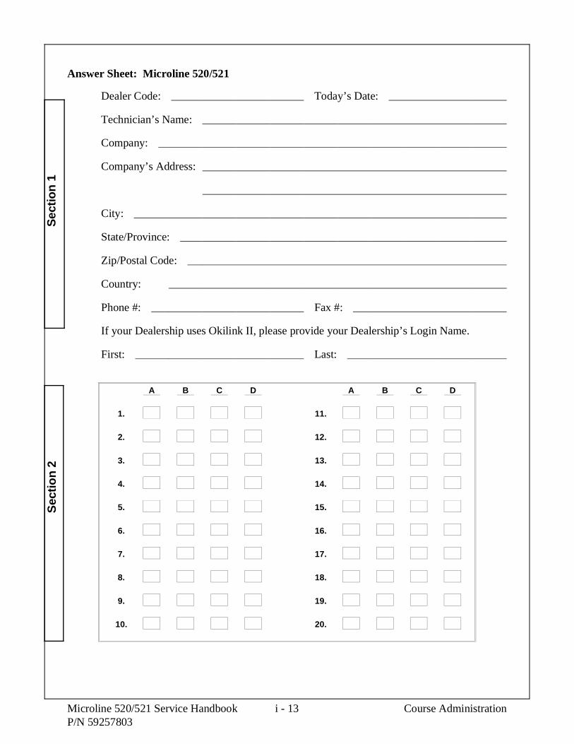
Answer Sheet: Microline 520/521
Dealer Code: Today’s Date:
Technician’s Name:
Company:
Company’s Address:
City:
State/Province:
Zip/Postal Code:
Country:
Phone #: Fax #:
If your Dealership uses Okilink II, please provide your Dealership’s Login Name.
First: Last:
A B C D A B C D
1. 11.
2. 12.
3. 13.
4. 14.
5. 15.
6. 16.
7. 17.
8. 18.
9. 19.
10. 20.
Sec
tion
1S
ectio
n 2
Microline 520/521 Service Handbook i - 13 Course AdministrationP/N 59257803

Course Critique: Microline 520/521
Dealer Code: Today’s Date:
Technician’s Name:
Company:
Company’s Address:
City:
State/Province:
Zip/Postal Code:
Country:
Phone #: Fax #:
1. Have you completed other Okidata Self-Study Service Training packages?
Yes No
2. Please rate this course.
Excellent Below Average
Above Average Poor
Average
3. Does your Dealership use Okilink II?
Yes No
If yes, please provide your Dealership’s Login Name.
First Name:
Last Name:
Course Administration i - 14 Microline 520/521 Service HandbookP/N 59257803

4. Comments
Microline 520/521 Service Handbook i - 15 Course AdministrationP/N 59257803

Certification Test: Microline 520/521
1. After installing the space motor, Okidata recommends that you check the printhead gap.
A. True
B. False
Correct Answer: APages 3-2 and 3-26, Service Handbook, Rev 01 and 02Pages 3-2, 3-24, and 3-66, Service Handbook, Rev 03
2. Refer to RAP 01. You have pressed the AC power switch to ON, but the unit does notpower ON. The next step is to
A. replace the fuse.
B. check if the AC cable is connected properly.
C. replace the space motor assembly.
D. remove the printhead.
Correct Answer: BPage 4-10, Service Handbook, Rev 01 and 02Page 4-24, Service Handbook, Rev 03
3. The + 40 vdc needed for the printhead and space motor drive can be verified at__________ on the main control (FJIM) board.
A. CN1 Pins 8 and 9
B. CN3 Pins 1 and 2
C. CN7 Pins 29 and 31
D. CN6 Pins 1 and 2
Correct Answer: CPage A-4, Service Handbook, Rev 01 and 02Page A-4, Service Handbook, Rev 03
Course Administration i - 16 Microline 520/521 Service HandbookP/N 59257803

4. According to Appendix A of the Service Handbook, one function of the main controlboard is to regulate the AC voltages from the power supply (transformer).
A. True
B. False
Correct Answer: APage A-4, Service Handbook, Rev 01 and 02Page A-4, Service Handbook, Rev 03
5. You are using RAP 11 to troubleshoot a printer. The unit cannot receive serialcommunication from the host. You have verified that the cable has the properconfiguration of pins. No ALARM LEDs are blinking. Your next step should be to
A. replace the transformer.
B. replace the RS 232-C serial board.
C. check your serial interface parameters.
D. replace the main control board (FJIM).
Correct Answer: CPage 4-26, Service Handbook, Rev 01 and 02Page 4-40, Service Handbook, Rev 03
Microline 520/521 Service Handbook i - 17 Course AdministrationP/N 59257803

6. The printer is processing a head overheat alarm. When the printhead temperature exceeds110 degrees Celsius, the printer switches to unidirectional print. When the printheadtemperature exceeds 118 degrees Celsius, the printer will
A. need a new space motor.
B. continue unidirectional print.
C. alternate between unidirectional print and bidirectional print.
D. stop printing.
Correct Answer: DPages 2-21, 2-28, and 4-31, Service Handbook, Rev 01 and 02Pages 1-11, 2-15, 2-32, and 4-21, Service Handbook, Rev 03
7. Before you begin troubleshooting an ALARM / LED display, you should always
A. replace the power supply.
B. check that all of the connectors of the printer are making good contact.
C. replace the main control board.
D. replace the operator panel.
Correct Answer: BPage 4-30, Service Handbook, Rev 01 and 02Page 4-20, Service Handbook, Rev 03
Course Administration i - 18 Microline 520/521 Service HandbookP/N 59257803

8. According to the Printer Handbook or Section Three of this Service Handbook, which ofthe following settings is NOT a default menu setting of the serial interfaceconfiguration?
A. Parity - Even
B. Serial Data - 8 bits
C. Protocol - Ready/Busy
D. Baud Rate - 9600 bps
Correct Answer: APage 90, Printer Manual User’s Documentation, Rev 01 and 02Page 3-81, Service Handbook, Rev 03
9. The ALARM lamp is flashing. The PROP and 10 cpi lamps are lit. Which alarm is theprinter experiencing?
A. Printhead Data Transfer Alarm
B. Printhead Type Alarm
C. Paper End Alarm
D. Space Motor Alarm
Correct Answer: BPage 4-29 and 4-30, Service Handbook, Rev 01 and 02Pages 4-19 and 4-20, Service Handbook, Rev 03
Microline 520/521 Service Handbook i - 19 Course AdministrationP/N 59257803

10. You install a new control board in the printer. What are the indications of an incorrectlypositioned cut sheet / continuous sensor lever?
A. The unit will not power-ON.
B. All lamps on the operator panel light.
C. The ALARM lamp lights and F1 on the control board blows.
D. The ALARM lamp lights and the unit will NOT automatically load paper.
Correct Answer: DPages i-7 and i-8, Service Handbook, Rev 01 and 02 OLD QUESTIONPage 3-16, Service Handbook, Rev 03 NEW QUESTION
11. What is the recommended ambient temperature and relative humidity (RH) for the printerwhile operating?
A. 41°F to 104°F, 20% to 80% (RH)
B. 41°F to 104°F, 10% to 70% (RH)
C. 41°F to 104°F, 20% to 50% (RH)
D. 41°F to 104°F, 20% to 90% (RH)
Correct Answer: APage 1-2, Service Handbook, Rev 01 and 02Page 1-4, Service Handbook, Rev 03
12. The Microline 520 and Microline 521 printers allow you to print up to eight different barcodes.
A. True
B. False
Correct Answer: APages 84, Printer Manual and 1-8, Service Handbook, Rev 01 and 02Page 1-7 and 1-8, Service Handbook, Rev 03
Course Administration i - 20 Microline 520/521 Service HandbookP/N 59257803

13. The Microline 520 and Microline 521 printers come with _____________ Kbyte ofresident RAM.
A. 32
B. 64
C. 128
D. 256
Correct Answer: CPage 1-4, Service Handbook, Rev 01 and 02Page 1-20, Service Handbook, Rev 03
14. Refer to RAP 02. The carriage is jammed. The ribbon is not jammed. What do you donext?
A. Install a new space motor.
B. Power OFF the printer, then power ON.
C. Remove the space motor assembly and inspect the teeth on the space rack andspace motor gear.
D. Replace fuse F1 on the main controller board.
Correct Answer: CPage 4-12, Service Handbook, Rev 01 and 02Page 4-26, Service Handbook, Rev 03
15. You must replace the line feed motor. The disassembly procedure also tells you toremove the line feed idle gear.
A. True
B. False
Correct Answer: BPage 3-54, Service Handbook, Rev 01 and 02Page 3-46, Service Handbook, Rev 03
Microline 520/521 Service Handbook i - 21 Course AdministrationP/N 59257803

16. Three items factor into printhead gap information.
1. Printhead Gap Adjustment (performed by a service technician)
2. Printhead Gap Adjust (set in the printer menu, under the Set-up Group)
3. Gap Control (set in the printer menu, under each [Paper Feed] Group)
A. True
B. False
Correct Answer: APage C-1, Service Handbook, Rev 01 and 02 OLD QUESTIONPages 1-12 and 2-18, Service Handbook, Rev 03 NEW QUESTION
17. Which of the following areas of the printer should NOT be lubricated?
1. Tractor pins
2. Pressure roller (Rubber Face)
3. Platen assembly (Rubber Face)
4. Teeth of gears in the gear case assembly
A. 1
B. 1 and 2
C. 1, 2, and 3
D. 1, 2, 3, and 4
Correct Answer: DPage 3-88 and 3-89, Service Handbook, Rev 01 and 02Page 3-91, Service Handbook, Rev 03
Course Administration i - 22 Microline 520/521 Service HandbookP/N 59257803

18. You are performing the printhead gap adjustment. The printhead gap is changed byturning the adjusting screw, located on the space motor assembly. Turning theadjusting screw counter-clockwise will increase the gap. Turning it clockwise willdecrease the gap.
A. True
B. False
Correct Answer: BPage 3-68, Service Handbook, Rev 01 and 02Page 3-68, Service Handbook, Rev 03
19. The ALARM lamp is flashing. The 15 cpi LED is lit. Which of the following should bereplaced first?
A. Printhead
B. Line feed motor
C. Space motor
D. Main control board and / or ROM
Correct Answer: DPage 4-30, Service Handbook, Rev 01 and 02Page 4-20, Service Handbook, Rev 03
Microline 520/521 Service Handbook i - 23 Course AdministrationP/N 59257803

20. Before resetting a printer menu to factory settings, Okidata recommends that you
A. run a self test.
B. perform the hex dump test.
C. power OFF the printer, then press and hold the LINE FEED while poweringON the printer.
D. print the menu.
Correct Answer: DPages 47, User’s Documentation and 3-81, Service Handbook, Rev 01 and 02Page 3-75, Service Handbook, Rev 03
Course Administration i - 24 Microline 520/521 Service HandbookP/N 59257803

SECTION ONE
SPECIFICATIONS


1.1 OVERVIEW
1.1.01 General Information
The Microline 520 and Microline 521 are letter quality, nine-pin, dot-matrix printers whichutilize OKISMART paper handling. Patented Okidata technology does away with the manualhead gap adjustment. The printer actually "reads and learns" the print medium being used, thenautomatically adjusts the head gap to the optimum distance. This autogapping process leads tolonger printhead life.
Options include the Bottom Feed Push Tractor, Cut-Sheet Feeder, Pull Tractor and SerialInterface Board.
The Microline 520 is an 80 column printer.
The Microline 521 is a 132 column printer.
Okidata’s one year limited warranty covers the parts, labor and printhead on both printers.
The following items are available for the printer.
OKISMART Typer - software which provides the flexibility for the Microline 590/521 tofunction like a typewriter on checks, labels and envelopes.
OKISMART Panel - a utility program that lets you control selected printer functions fromyour personal computer.
Scalable Fonts - 14 scalable fonts, available on diskette.
NOTE:
The OkiSmart software includes three programs.
1. OkiSmart Control
2. OkiSmart Panel Emulator
3. OkiSmart Setup
Refer to the Printer Handbook for more information.
Microline 520/521 Service Handbook 1 - 1 SpecificationsP/N 59257803

1.2 PHYSICAL SPECIFICATIONS
1.2.01 Dimensions
NOTE:
Dimensions INCLUDE the platen knob, acoustic cover, and paper separator.
Microline 520
Width: 16.9 inches (43 centimeters)
Depth: 14.9 inches (37.8 centimeters)
Height: 6.5 inches (16.5 centimeters)
Microline 521
Width: 23 inches (58.4 centimeters)
Depth: 14.9 inches (37.8 centimeters)
Height: 6.5 inches (16.5 centimeters)
1.2.02 Printer Weight
Microline 520
17.6 pounds (8.0 kilograms)
Microline 521
23.1 pounds (10.5 kilograms)
Specifications 1 - 2 Microline 520/521 Service HandbookP/N 59257803

1.3 POWER REQUIREMENTS
1.3.01 Input Power
120 VAC: +5.5 / -15%
230/240 VAC: +10 / -14%
1.3.02 Power Consumption
Operating: 110 VA
Idle: 40 VA
Local Test: 70 VA
1.3.03 Power Frequency
120 VAC: 60 Hz +/- 2%
230/240 VAC: 50/60 Hz +/- 2%
Microline 520/521 Service Handbook 1 - 3 SpecificationsP/N 59257803

1.4 ENVIRONMENTAL CONDITIONS
1.4.01 Acoustic Rating
Near Letter Quality Mode
Microline 520 54.9 dBA
Microline 521 54.4 dBA
Utility Mode
Microline 520 57.2 dBA
Microline 521 56.9 dBA
Quiet Mode
Microline 520 52.5 dBA
Microline 521 52.3 dBA
1.4.01 Altitude
10,000 feet (3,050 meters)
1.4.03 Ambient Temperature and Relative Humidity (RH)
While operating: 41 to 104 degrees Fahrenheit (5 to 40 degrees Celsius)
Operating humidity: 20% to 80% RH
While in storage: 14 to 122 degrees Fahrenheit ( - 10 to 50 degrees Celsius)
Storage humidity: 5% to 95% RH
Specifications 1 - 4 Microline 520/521 Service HandbookP/N 59257803

1.5 AGENCY APPROVALS
1.5.01 Listings
UL No: UL Standard No. 1950 D3
CSA No: CSA Standard 22.2-950 D3
FCC: FCC Certified per Part 15, Subject J, Class B
IEC: IEC 950
VDE: VDE 0805 VDE 0875 Class B
BS: BS 7002
Microline 520/521 Service Handbook 1 - 5 SpecificationsP/N 59257803

1.6 OPERATIONAL SPECIFICATIONS
1.6.01 Character Matrix Sizes
Table of Print Speed and Character Matrix
Mode Near LetterQuality
Utility High SpeedDraft
Speed 80 (12 cpi) 320 (12 cpi) 427 (12 cpi)Matrix (H x V) 17 x 13 9 x 7 7 x 7
1.6.02 Characters Per Line
Microline 520
Characters Per Line Characters Per Inch80 1096 12
120 15137 17.1160 20
Microline 521
Characters Per Line Characters Per Inch136 10163 12204 15233 17.1272 20
1.6.03 Character Pitches
5, 6, 8.5, 10, 12, 15, 17.1, 20
Specifications 1 - 6 Microline 520/521 Service HandbookP/N 59257803

1.6.04 Character Sets
Standard ASCII
EPSON Character Set I & II
IBM Character Set I, II & All Characters
Foreign Character Substitution
International Character Sets
Code Page 850, 860, 863, 865 and 437
Line Graphics
Bar Code
Code 39
UPC A
UPC E
EAN 8
EAN 13
Interleaved 2 of 5
Code 128 (A, B, C)
Postnet
1.6.05 Emulations
NOTE:
The emulations are co-resident
Epson FX
IBM Proprinter
Microline Standard
Microline 520/521 Service Handbook 1 - 7 SpecificationsP/N 59257803

1.6.06 Fonts
Near Letter Quality
Courier
Utility
Gothic
High Speed Draft
Gothic
Bar Code
Code 39
UPC A
UPC E
EAN 8
EAN 13
Interleaved 2 of 5
Code 128 (A, B, C)
Postnet
1.6.07 Front Panel Switches
SELECT / Menu Micro Feed Up / Down
Shift Paper Park
Line Feed Pitch Selection
FORM FEED / Load Print Quality Selection
Top of Form Tear
Quiet Reset
1.6.08 Graphics Resolution
Graphics Resolution: 288 (horizontal) x 144 (vertical) dots per inch (DPI) maximum
1.6.09 Interface
Standard
Centronics Parallel
Optional
RS232C Serial
Specifications 1 - 8 Microline 520/521 Service HandbookP/N 59257803

1.6.10 Line Feed Increments
Fixed
6 lines per inch (lpi) [0.167 inch (4.23 millimeters)]
8 lines per inch (lpi) [0.125 inch (3.175 millimeters)]
Variable
n/60 inch
n/72 inch
n/144 inch
n/216 inch
1.6.11 Line Feed Time
65 milliseconds 6 lines per inch (lpi)
6 milliseconds 8 lines per inch (lpi)
1 second 5.0 inches (Continuous paper feed rate)
1.6.12 Menu Mode
Switch ActionPaper Park Prints the entire menu.
Line Feed / Reverse Selects Group FunctionFORM FEED / Load Selects Item
Tear Selects Item ValueSEL / Menu Exits Menu Mode, Enters Select
Microline 520/521 Service Handbook 1 - 9 SpecificationsP/N 59257803

1.6.13 Paper Feed Methods
Standard
Friction Feed (Top)
Rear Push Tractor (Rear)
Optional
Pull Tractor (Bottom)
Bottom Push Tractor Feed (Bottom)
Single-Bin Cut Sheet Feeder (Top)
CSF 5000 - Narrow
CSF 5001 - Wide
1.6.14 Paper Feed Paths
Top Feed (Standard)
Rear Feed (Standard)
Bottom Feed (by using an Optional feed mechanism)
Special Features
Paper Park
Automatic Paper Loading
Forms Tear Off
1.6.15 Paper Loading
Auto Loading (Top Feed)
Press FORM FEED / Load switch to feed paper to default position
1.6.16 Paper Out Detection
Distance from end of paper
Rear Feed: 0.5 inches (12.7 mm)
Bottom Feed: 0.5 inches (12.7 mm)
Top Feed: 0.5 inches (12.7 mm)
1.6.17 Paper Tear Capabilities
Forms Tear-0ff (sharp edge on access cover)
Metal Tear Bar (with optional bottom feed tractor unit)
Specifications 1 - 10 Microline 520/521 Service HandbookP/N 59257803

1.6.18 Print Method
Printhead Type
General Information
Impact: Dot Matrix
9 pin printhead
.0134 inch (0.34 millimeter) diameter pins
Overheat Protection
When printhead temperature exceeds 110 degrees Celsius, the printer stops bi-directionalprinting. Uni-directional printing begins.
If the temperature exceeds 118 degrees Celsius, printing stops.
Printing will resume when the printhead temperature drops below 118 degrees Celsius.
NOTE:
Refer to Section Two for more information on printhead operation.
Microline 520/521 Service Handbook 1 - 11 SpecificationsP/N 59257803

Printhead Gap Information
Three items factor into printhead gap information.
1. Printhead Gap Adjustment
This is a SERVICE ADJUSTMENT made by a technician.
It is covered in Section 3.3 of this Service Handbook.
The Adjustment measures 0.014, +/- 0.001 inches (0.35, +/- 0.03 mm).
2. Printhead Gap Adjust
This is a MENU ITEM in the SET-UP Group.
It fine tunes the automatic setting of the printhead gap.
The settings are 0, 1, and -1.
0 is the factory default.
Use 1 to darken print (if output is consistently light).
Use - 1 to lighten print (if output is consistently dark).
3. Gap Control
This is a MENU ITEM in each [Paper Feed] Group.
The Groups are REAR FEED, BOTTOM FEED, and TOP FEED.
Gap Control determines how the printhead gap is set.
The settings are listed below.
Auto Gap, Semi Auto Gap, 1, 2, 3, 4, 5, 6, 7, 8, 9
An explanation of each setting follows.
Specifications 1 - 12 Microline 520/521 Service HandbookP/N 59257803

Auto Gap
This is the factory default.
Automatically determines paper thickness of the first page.
During single-sheet feed, each page’s thickness is checked while a job isprinting.
Semi Auto Gap
Similar to Auto Gap.
Automatically determines paper thickness of the first page.
During single-sheet feed, each page’s thickness IS NOT checked "while"a job is printing.
1, 2, 3, 4, 5, 6, 7, 8, 9
Used when the same paper is used ALL of the time.
Bypasses the automatic head gap adjustment.
1 is the narrowest gap setting.
9 is the widest gap setting.
1-7-01.tif
Microline 520/521 Service Handbook 1 - 13 SpecificationsP/N 59257803

1.6.19 Print Modes
Near Letter Quality
Utility
High Speed Draft
1.6.20 Print Speed
Table of Print Speed and Character Matrix
Mode Near LetterQuality
Utility High SpeedDraft
Speed 80 (12 cpi) 320 (12 cpi) 427 (12 cpi)Matrix (H x V) 17 x 13 9 x 7 7 x 7
Specifications 1 - 14 Microline 520/521 Service HandbookP/N 59257803

1.7 PAPER SPECIFICATIONS
CAUTION:
Use Bottom Feed and/or optional Pull Tractor for card stock and labels.
1.7.01 Types
Card Stock
Weight: 120 lbs. (450 g/m2) Maximum
Width: Microline 520 5 to 8 inches (12.7 to 20.3 centimeters)
Microline 521 5 to 14 inches (12.7 to 35.6 centimeters)
Length: 3 to 17 inches (7.62 to 43.18 centimeters)
Thickness: .017 inches (0.44 millimeters)
Paper Feed Path: Bottom
Printhead GapInformation: Refer to the Printhead Gap Information, Section 1.6
Continuous Form
Weight:
Single Part 12 - 24 lb. (45 to 90 g/m2)
Multi-Part,Carbonless 9 - 11 lb. (35 to 40 g/m2)
Multi-Part,Interleaf Paper 10 - 12 lb. (38 to 45 g/m2) Carbon 9 lb. (35 g/m2)
Width: Microline 520 3.5 to 10.5 inches (8.8 to 26.6 centimeters)
Microline 521 3.5 to 16.5 inches (8.8 to 41.9 centimeters)
Length: 3 to 17 inches (7.62 to 43.18 centimeters)
Thickness: 0.014 inches (0.36 millimeters) Rear Feed0.017 inches (0.44 millimeters) Bottom Feed
Paper Feed Path: Rear or Bottom
Printhead GapInformation: Refer to the Printhead Gap Information, Section 1.6
Microline 520/521 Service Handbook 1 - 15 SpecificationsP/N 59257803

Cut Sheet
Weight: 12 to 24 lbs. (45 to 90 g/m2)
Width: 7.2 to 14.3 inches (18.3 to 36.3 centimeters)
Width: Microline 520 7.2 to 8.5 inches (18.2 to 21.5 centimeters)
Microline 521 7.2 to 14.3 inches (18.2 to 36.3 centimeters)
Length: 3 to 17 inches (7.62 to 43.18 centimeters)
Thickness: 0.014 inches (0.325 millimeters) Maximum
Paper Feed Path: Top
Printhead GapInformation: Refer to the Printhead Gap Information, Section 1.6.
Envelopes
Weight: 24 lbs. (90 g/m2) Maximum
Size:
Single Feed
Minimum: 6.5 x 3.6 inches (16.5 x 9.1 centimeters)
Maximum: 9.5 x 4.1 inches (24.1 x 10.4 centimeters)
Continuous
Non-overlap type
Thickness: .014 inches (.325 millimeters) Maximum
Paper Feed Path: Bottom
Printhead GapInformation: Refer to the Printhead Gap Information, Section 1.6.
Specifications 1 - 16 Microline 520/521 Service HandbookP/N 59257803

Labels
Weight: N/A
Width: Microline 520 3.5 to 10.5 inches (8.8 to 26.6 centimeters)
Microline 521 3.5 to 16.5 inches (8.8 to 41.9 centimeters)
Length: 3 to 17 inches (7.62 to 43.18 centimeters)
Thickness: .011 inches (0.28 mm) Maximum (including backing)
Paper Feed Path: Bottom
Printhead GapInformation: Refer to the Printhead Gap Information, Section 1.6.
CAUTION:
Use Bottom Feed and/or optional Pull Tractor for card stock and labels.
Transparency
NOTE:
Roller marks may mar the transparency under high temperature / high humidityconditions.
Weight: 12 to 24 lbs. (45 to 90 g/m2)
Width: Microline 520 7.2 to 8.5 inches (18.2 to 21.5 centimeters)
Microline 521 7.2 to 14.3 inches (18.2 to 36.3 centimeters)
Length: 3 to 17 inches (7.62 to 43.18 centimeters)
Thickness: 0.14 inches (0.36 millimeters)
Paper Feed Path: Top
Printhead GapInformation: Refer to the Printhead Gap Information, Section 1.6.
Microline 520/521 Service Handbook 1 - 17 SpecificationsP/N 59257803

1.7.02 Length
NOTE:
The recommended length is specific to paper type.
Rear Feed
Minimum 3 inches (7.62 centimeters)
Maximum 17 inches (43.18 centimeters)
Bottom Feed
Minimum 3 inches (7.62 centimeters)
Maximum 17 inches (43.18 centimeters)
Top Feed
Minimum 3 inches (7.62 centimeters)
Maximum 17 inches (43.18 centimeters)
1.7.03 Number of Copies
Original + 4 Interleaf
Original + 4 Carbonless
Original Cut Sheet
1.7.04 Thickness
0.014 inches / 0.36 mm Maximum Thickness, Rear Feed
0.017 inches / 0.44 mm Maximum Thickness, Bottom Feed
Specifications 1 - 18 Microline 520/521 Service HandbookP/N 59257803

1.7.05 Weight
NOTE:
The recommended weight is specific to paper type.
Minimum: 9 lb. (35 g/m2)
Maximum: 120 lb. (90 g/m2)
1.7.06 Width
NOTE:
The recommended width is specific to paper type.
Paper
Microline 520
Minimum: 3.5 inches ( 8.8 centimeters)
Maximum: 10.5 inches (26.6 centimeters)
Microline 521
Minimum: 3.5 inches ( 8.8 centimeters)
Maximum: 16.5 inches (41.9 centimeters)
Printing Area
Microline 520 8 inches Maximum
Microline 521 13.6 inches Maximum
Microline 520/521 Service Handbook 1 - 19 SpecificationsP/N 59257803

1.8 MEMORY SPECIFICATIONS
1.8.01 EEPROM
1 Kbit serial EEPROM (used to store Menu data)
1.8.02 EPROM
1 MBit EPROM (Printer Control Program - Fonts)
1.8.03 RAM
128 Kbyte Total Resident RAM
Used as
Receive Buffer
Receive Buffer Size is selected through the Menu.
Settings are: 64 K, 32 K, 1 line
Print Buffer
DLL Buffer
Scratch Pad
Specifications 1 - 20 Microline 520/521 Service HandbookP/N 59257803
1.9 CONSUMABLES
1.9.01 Ribbon
CAUTION:
Using a non-Okidata ribbon may damage the printhead and void any warranties.
Material
Nylon fabric, cartridge type, re-inking
Type
Black Ribbon
Life (On average, at 10 characters per inch, Utility Mode)
4 million characters
Microline 520/521 Service Handbook 1 - 21 SpecificationsP/N 59257803

1.10 OPTIONS
1.10.01 Cut Sheet Feeders
Single Bin
The CSF-5000 is a narrow feeder for the Microline 520.
Single Bin with envelope capability
Paper Width: 7.2" to 8.5" (18.3 cm to 36.3 cm)
Paper Length: 10.1" to 14" (25.6 cm to 35.6 cm)
Capacity: 170 sheets (16 lb.), 100 sheets (20 lb.)
The CSF-5001 is a wide feeder for the Microline 521.
Single Bin with envelope capability
Paper Width: 7.2" to 14.3" (18.3 cm to 36.3 cm)
Paper Length: 10.1" to 14" (25.6 cm to 35.6 cm)
Capacity: 170 sheets (16 lb.), 100 sheets (20 lb.)
Dual Bin
P/N 70022601 is a narrow feeder for the Microline 520.
Dual Bin with envelope capability
Paper Width: 7.2" to 8.5" (18.3 cm to 36.3 cm)
Paper Length: 10.1" to 14" (25.6 cm to 35.6 cm)
Capacity: 170 sheets (16 lb.), 100 sheets (20 lb.)
P/N 70022801 is a wide feeder for the Microline 521.
Dual Bin with envelope capability
Paper Width: 7.2" to 14.3" (18.3 cm to 36.3 cm)
Paper Length: 10.1" to 14" (25.6 cm to 35.6 cm)
Capacity: 170 sheets (16 lb.), 100 sheets (20 lb.)
1-1-01.pcx
Specifications 1 - 22 Microline 520/521 Service HandbookP/N 59257803

1.10.02 Pull Tractor Kit
NOTE:
The Pull Tractor Kit (P/N 70023001) is a narrowfeeder for the Microline 520.
The Pull Tractor Kit (P/N 70023201) is a widefeeder for the Microline 521.
Bottom Feed
Rear Feed (For Push/Pull Operation)
Paper Types: Continuous Feed and Labels
1.10.04 Bottom Push Tractor Kit
NOTE:
The Bottom Push Tractor Kit (P/N 70022901) is anarrow feeder for the Microline 520.
The Bottom Push Tractor Kit (P/N 70023101) is awide feeder for the Microline 521.
Bottom Feed
Paper Type: Continuous Feed
Includes: Stand and Metal Tear Bar
1.10.05 Serial Interface
Super-Speed 19.2K RS-232C
Ready/Busy/X-On/X-Off Protocols
Can be configured through the Menu or OKISmart Utility Program
1-1-02.pcx
1-1-03.pcx
Microline 520/521 Service Handbook 1 - 23 SpecificationsP/N 59257803

1.10.06 Roll Paper Stand
Adapts printer for use with roll-type paper (Model 520 only)
Includes: Stand, Support, Cord and DIN plug for connectionto printer
1.10.08 OKISmart Typer Utility
Obtained via BRC (Business Reply Card) packaged with printer
Includes: Typewriter Mode, Form Creation Utility and Barcode Utility
1.10.09 OKISmart Panel Utility
Obtained via BRC (Business Reply Card) packaged with printer
Includes: Front Panel Control Utility and Drivers for Windows 3.0 & 3.1
NOTE:
The OKISmart software includes three programs.
1. OKISmart Control
2. OKISmart Panel Emulator
3. OKISmart Setup
Refer to the Printer Handbook for more information.
1-1-05.pcx
Specifications 1 - 24 Microline 520/521 Service HandbookP/N 59257803

1.11 RELIABILITY
1.11.01 Mean Time Before Failure (MTBF)
Approximately 6,000 hours: 25% duty cycle / 35% page density
1.11.02 Mean Time To Repair (MTTR)
Approximately 15 minutes to major sub-assembly level
1.11.03 Printer Life
Approximately 16,000 hours of power-on time: 25% duty cycle / 35% page density
1.11.04 Printhead Life
Average 200 million characters in 10 cpi utility mode @ normal 25% duty,35% page density
1.11.05 Ribbon Life
Approximately 4 million characters
1.11.06 Warranty (Limited)
One year, parts and labor
1.11.07 Service
Authorized OKIdata Service Centers
Microline 520/521 Service Handbook 1 - 25 SpecificationsP/N 59257803

This page was intentionally left blank.
Specifications 1 - 26 Microline 520/521 Service HandbookP/N 59257803

SECTION TWO
PRINCIPLES OF OPERATION


2.1 ELECTRICAL OPERATION
The printer is comprised of the electrical components listed below.
Main Control Board
Power Supply Assembly
Transformer
Filter Board
Operator Panel
Space Motor / Line Feed Motor
Printhead
Microline 520/521 Service Handbook 2 - 1 Principles of OperationP/N 59257803

2.1.01 Main Control Board
The main control board is made up of the microprocessor, peripheral circuits, drive circuits,sensors and interface connectors.
The power to the main control board is supplied by the transformer assembly through a wireharness. The power to other electrical parts (line feed motor, space motor and printhead)is provided by the power supply circuitry through connectors on the main control board.
Microprocessor (MPU) (Location 04C: 67X640)
16 bit MPU, using CMOS technology.
The MPU contains a 20 bit address bus, a 16 bit data bus.
The MPU can access 1 Mbyte of program memory and 1 Mbyte of data memoryspace.
The microprocessor controls the entire printer by executing the control programthrough the LSIs and the driver circuits.
Principles of Operation 2 - 2 Microline 520/521 Service HandbookP/N 59257803

Block Diagram
2-1-01a.tif
Microline 520/521 Service Handbook 2 - 3 Principles of OperationP/N 59257803

Program ROM
Location 05CA: 27C1024
This 64k x 16 bit (1Mbit) EPROMcontains the control program for theprinter. The MPU executes theinstructions contained in this program.
The Program ROM is assigned to theprogram memory area of the MPU andinstructions are fetched by the PSENsignal of the MPU.
RAM
Location 05CB: 511664Z
The RAM is CMOS dynamicRAM with 65,536 words x 16-bitconfiguration. It is used as areceive buffer, print buffer andwork buffer.
2-1-01b.tif
2-1-01c.tif
Principles of Operation 2 - 4 Microline 520/521 Service HandbookP/N 59257803

LSI
Location 04B: MSM79VO35
Detects the output of the two-phasesensor on the DC space motor tocontrol the motor drive phase.
Transmits and receives serial data toand from the printhead based on the dottiming (which is derived from the spacemotor speed).
Controls the external interface. TheLSI is connected to the MPU.
Electrically ErasableProgrammable Read Only Memory(EEPROM)
(Location 03C: 93CS46)
The EEPROM is a CMOS serialI/O type memory (EEPROM). Itis capable of electrically erasingand writing 1,024 bits.
The EEPROM contains the menudata and the head drive timecorrection data.
2-1-01e.tif
2-1-01d.tif
Microline 520/521 Service Handbook 2 - 5 Principles of OperationP/N 59257803

2.1.02 Initialization
This printer is initialized when the printer is powered on or when the I-PRIME-N signal is inputfrom the host via the parallel interface.
The steps in Printer Initialization are listed below.
The RST-N signal is output from the reset circuit to reset the MPU and LSIs.
The program is executed and the LSIs are reset by the MPU via IORST-N.
NOTE:
A reset operation initiated by I-PRIME does not reset the MPU.
The program sets the LSI (02D) mode, checks the memory (ROM/RAM), then executescarriage homing and determines the phase of the line feed motor.
Finally, the program establishes the interface signals (P-I/F: ACK-P signal sending, andS-I/F: BUSY-N signal off) and lights the SELECT lamp to indicate that the printer is inthe ON-LINE state.
2-1-02.tif
Principles of Operation 2 - 6 Microline 520/521 Service HandbookP/N 59257803

2.1.03 Parallel Interface Control
The parallel data input from the host to the interface LSI is latched to the internal register at thefalling edge of the STROBE-N signal.
The LSI sets the BUSY-N signal to inform the host that the data is being processed. The LSIalso outputs the RXD-N signal to inform the MPU of data reception. The data is read uponreceiving the RD-N signal from the MPU.
When the data processing is complete, the BUSY-N signal is disabled and the ACK-N signal issent to request the next data. When the buffer is full and reception is not desired, the BUSYsignal is sent to request data transmission be stopped.
2-1-03a.tif
2-1-03b.pcx
Microline 520/521 Service Handbook 2 - 7 Principles of OperationP/N 59257803

2.1.04 Print Control
The print data is transmitted as serial data from the LSI to the control circuit and the drivercontained in the printhead.
After the data is printed, the sensor analog circuit controlling each pin returns the pin stroke datato the MPU. The MPU will make an automatic head gap adjustment. This feedback system setsthe optimum drive time for each pin in order to maintain high print quality.
In the case of envelopes, where the medium thickness varies as the printhead moves along theplaten, the strike force of the pins changes to compensate for the differences in thickness.
LSI/Printhead Interface
The connection between the LSI and the printhead is made with the bi-directional serial databus. The LSI transmits the print data as serial data to the logic circuit of the printhead. Theprinthead returns serial data from the printhead sensor analog circuit to the LSI. Thisinformation is used to determine the optimum drive time for the next print request.
The logic circuit of the printhead signals the LSI if a parity error is detected in the print data.
2-1-04a.tif
2-1-04b.tif
Principles of Operation 2 - 8 Microline 520/521 Service HandbookP/N 59257803

Gap Adjust Control
The Gap Adjust LSI receives strokelength information for all of theprinthead pins from the sensoranalog circuit. The Gap Adjust LSIthen sets the optimum printhead gapfor the printing medium.
NOTE:
Refer to Section 2.2.03 for adecription of the mechanicalprocess.
All values in the below chartare in millimeters
Print Compensation Control
The printhead compensates for the shape of the platen as shown below.
NOTE:
Also refer to Section 2.1.07 - Head Drive Time
2-1-04c.tif
2-1-04d.tif
Microline 520/521 Service Handbook 2 - 9 Principles of OperationP/N 59257803

2.1.05 Space and Line Feed (SP/LF) Motor Control
The LSI (Location 04B: MSM79V035) generates the space motor and the line feed motorcontrol signals according to commands received from the MPU. These signals are sent to theSP/LF motor driver.
Line Feed Motor Control
The SP/LF motor driver (Location 5A: MHM2025) drives the line feed motor in two-phasebipolar, based on the phase changeover data output from the LSI.
The serial data from the LSI (04B: MSM79V035) is processed by a register contained in theSP/LF motor driver to measure the overdrive time and to change the phase.
2-1-05a.tif
2-1-05d.tif
Principles of Operation 2 - 10 Microline 520/521 Service HandbookP/N 59257803

Space Motor Control
The SP/LF motor driver(Location 5A: MHM2025)drives the three-phase brushlessmotor. Motor movement isbased on the phase signal(SPU,SPV and SPW) and thespeed instruction data from theLSI. The MPU can identify thecurrent speed of the space motorby measuring the pulse width ofthe output (Phase A, Phase B)of the encoder disk sensor.
After comparing the target speedfor each print mode with the actualspeed, the motor is accelerated ordecelerated to maintain the desiredspeed for each print mode.
Encoder Disk
As the space motor operates, theencoder disk spins. When theencoder disk interrupts the photosensors, the signals Phase A andPhase B are generated. The LSI(Location 04B: MSM79V035)divides these edge pulse signals(the frequency division is basedon the selected print pitch) togenerate the signal IPT. The IPTsignal provides dot-on timingand carriage position detectiontiming.
2-1-05b.tif
2-1-05c.tif
Microline 520/521 Service Handbook 2 - 11 Principles of OperationP/N 59257803

2.1.06 Operation Panel
The Serial I/O Port (Ports 20 - 23) of the MPU reads the operation panel switch data from theoperation panel control LSI (Location IC1: BUS148S).
A two byte (15 bits +1 parity bit (even parity)) command (OPTXD) is transmitted from the MPUto the operation panel LSI in synchronization with the OPCLK signal. Once the LSI decodes thecommand, the command must pass a command code check and have no parity errors. Then, thespecified I/O control will return the two byte command response to the MPU.
2-1-06a.tif
Principles of Operation 2 - 12 Microline 520/521 Service HandbookP/N 59257803

2-1-06b.tif
Microline 520/521 Service Handbook 2 - 13 Principles of OperationP/N 59257803

2.1.07 Alarm Circuit
Driver Circuit Alarm Processing
The printhead driver output and the head gap magnet output drive signals are monitored at R29and C8. The POWER OFF-P signal is output by the comparator (Location 02C: IC2901) whendriven for more than the specified time. This signal becomes the ALM signal. The ALM signalis sent to the power supply board and causes the DC voltages to be turned off.
Low Motor Drive Voltage Alarm
+40V is converted into the POWLEV signal (0 vdc to +5 vdc) by the voltage divider network ofR542 and R544, then input to the A/D port of the MPU. The value of this voltage is used tocontrol the drive time and the print speed (pass number) of the head.
2-1-07a.tif
2-1-07b.tif
Principles of Operation 2 - 14 Microline 520/521 Service HandbookP/N 59257803

Head Drive Time
The head drive time is modified to compensate for the amount of the voltage drop of thePOWLEV signal. By monitoring the voltage drop every 500 microseconds, the MPU is able tocontrol and maintain the impact necessary for each printhead pin.
Print Speed
Actual Voltage (+40 vdc) Passes Required Relative Print Speed+34 vdc or greater 1 100%+32 vdc to +34 vdc 1 Approximately 85%+30 vdc to +32 vdc 1 Approximately 50%
+30 vdc or less 2 Less than 50%
Head Overheat Alarm Processing
If the printhead temperature exceeds 110 degrees Celsius, the printer will switch touni-directional print. If the temperature exceeds 118 degrees Celsius, printing will stop. Oncethe printhead cools, printing will resume.
Two thermistors are used to monitor the printhead temperature. One is contained in theprinthead. The other is in the printhead driver.
A thermistor in the printhead prevents over-heating of the coil during periods of continuousbi-directional printing. If the temperature of the coil exceeds the pre-determined limits, thecontrol circuit detects the thermistor signal (TSD).
Another thermistor monitors the temperature of the printhead driver. If the temperature of thedriver exceeds the pre-determined limits, the control circuit detects the thermistor signal (TSD).
The voltage of the TSD signal is monitored at the MPU A/D port to control the pass number andprint method (uni-directional / bi-directional) at each of seven levels.
2-1-07c.tif
Microline 520/521 Service Handbook 2 - 15 Principles of OperationP/N 59257803

2.1.08 Power Supply Circuit
The switching type power supply circuit supplies the +5 vdc, +/-8 vdc, 10 VAC and +40 vdc.
Table of Output Voltages
Voltage / Signal Purpose+5 vdc IC logic levels, LED drive voltages+8 vdc Serial interface line voltage, comparator IC
+10 VAC Serial interface line voltage and the printhead analog circuit+40 vdc Printhead, space motor and line feed motor drive voltage
2-1-08.tif
Principles of Operation 2 - 16 Microline 520/521 Service HandbookP/N 59257803

2.2 MECHANICAL OPERATION
2.2.01 Printhead Mechanism
The printhead is a spring-charged, 9-pin printhead. It is attached to the carriage, which movesparallel to the platen. Electrically, the printhead is controlled by the main control board via thecarriage cable and the space motor.
The printhead is composed of the following parts.
Wire Guide
Spring Assembly
Wire, Armature, Spring, Yoke, Spacer
Magnet Assembly
Magnet, Core, Coil, Yoke
Printed Circuit Board
Logic Control, Print Driver, Analog Sensor Control and Thermistor
Cooling Fin
2-2-01a.tif
Microline 520/521 Service Handbook 2 - 17 Principles of OperationP/N 59257803

Printhead Gap Information
Three items factor into printhead gap information.
1. Printhead Gap Adjustment
This is a SERVICE ADJUSTMENT made by a technician.
It is covered in Section 3.3 of this Service Handbook.
The Adjustment measures 0.014, +/- 0.001 inches (0.35, +/- 0.03 mm).
2. Printhead Gap Adjust
This is a MENU ITEM in the SET-UP Group.
It fine tunes the automatic setting of the printhead gap.
The settings are 0, 1, and -1.
0 is the factory default.
Use 1 to darken print (if output is consistently light).
Use - 1 to lighten print (if output is consistently dark).
3. Gap Control
This is a MENU ITEM in each [Paper Feed] Group.
The Groups are REAR FEED, BOTTOM FEED, and TOP FEED.
Gap Control determines how the printhead gap is set.
The settings are listed below.
Auto Gap, Semi Auto Gap, 1, 2, 3, 4, 5, 6, 7, 8, 9
An explanation of each setting follows.
Principles of Operation 2 - 18 Microline 520/521 Service HandbookP/N 59257803

Auto Gap
This is the factory default.
Automatically determines paper thickness of the first page.
During single-sheet feed, each page’s thickness is checked while a job isprinting.
Semi Auto Gap
Similar to Auto Gap.
Automatically determines paper thickness of the first page.
During single-sheet feed, each page’s thickness IS NOT checked "while"a job is printing.
1, 2, 3, 4, 5, 6, 7, 8, 9
Used when the same paper is used ALL of the time.
Bypasses the automatic head gap adjustment.
1 is the narrowest gap setting.
9 is the widest gap setting.
1-7-01.tif
Microline 520/521 Service Handbook 2 - 19 Principles of OperationP/N 59257803

Interconnect Diagram: Control Board to Printhead
NOTE:
The printhead coil resistance values ARE NOT LISTED.
The individual printwire control lines CANNOT be accessed on this printhead.
2-2-01b.pcx
Principles of Operation 2 - 20 Microline 520/521 Service HandbookP/N 59257803

Line Feed Motor Resistance
The resistance of each coil should be approximately 13 ohms.
Space Motor Resistance
The resistance of each coil should be approximately 5 ohms.
2-2-01c.pcx
2-2-01d.pcx
Microline 520/521 Service Handbook 2 - 21 Principles of OperationP/N 59257803

Printhead Operation
When the printhead is idle, the armature is attracted to the permanent magnet. The print wires,which are attached to each armature, are then concealed inside the wire guide.
When a signal to print a character is received, current flows through a coil. The magnetic fieldgenerated by the coil opposes the magnetic field between the armature and the permanentmagnet. The armature is then driven in the direction of the platen by the force of the armaturespring. The print wire (which is attached to the armature) protrudes from the tip of the wireguide and strikes the paper through the ribbon. This prints a dot on the paper.
As the armature gets closer to the electrode of the analog sensor, the capacitance between themincreases and a small amount of current flows. This current is amplified and sent to the logiccontrol LSI to indicate armature activity. In order to attain optimum drive time, this informationis transferred to the MPU. The MPU continually modifies the head gap to maintain the optimumdrive time condition.
The analog sensor element monitors all of the pins. The difference in pin stroke due to thecurvature of the platen is compensated for at the logic control section of the printhead and is nottransferred to the MPU.
After the character has been printed, the permanent magnet attracts the armature and the printwires are retracted into the wire guide.
Printhead Temperature
If the printhead temperature exceeds 110 degrees Celsius, the printer will switch touni-directional print. If the temperature exceeds 118 degrees Celsius, printing will stop. Oncethe printhead cools, printing will resume.
Two thermistors are used to monitor the printhead temperature. One is contained in theprinthead. The other is in the printhead driver.
A thermistor in the printhead prevents over-heating of the coil during periods of continuousbi-directional printing. If the temperature of the coil exceeds the pre-determined limits, thecontrol circuit detects the thermistor signal (TSD).
Another thermistor monitors the temperature of the printhead driver. If the temperature of thedriver exceeds the pre-determined limits, the control circuit detects the thermistor signal (TSD).
The voltage of the TSD signal is monitored at the MPU A/D port to control the pass number andprint method (uni-directional / bi-directional) at each of seven levels.
Principles of Operation 2 - 22 Microline 520/521 Service HandbookP/N 59257803

2-2-01e.pcx
Microline 520/521 Service Handbook 2 - 23 Principles of OperationP/N 59257803

2.2.02 Spacing Mechanism
The spacing mechanism consists of a carriage shaft (mounted parallel to the platen), and acarriage frame which moves along the shaft. The carriage frame is driven by a DC servo motormounted on the carriage frame. Items included in the spacing mechanism are listed below.
Space Motor Assembly
DC Servo Motor
Motor Gear
Sensor
Encoder Disk
Carriage Frame
Carriage Shaft
Space Rack
Spacing Operation
The carriage frame, which contains the printhead and space motor, moves along the carriageshaft parallel to the platen. When the space motor rotates, the driving force is transmitted to themotor gear. As the motor gear rotates, the carriage moves along the platen. For everyrevolution of the DC servo motor, the carriage frame moves 0.8 inch (20.32 mm).
As the DC servo motor rotates, a slotted disk (called the encoder disk), rotates with the servomotor and passes through the photosensor. The position of the carriage frame can be determinedby counting the pulses generated by the photosensors.
In the same way, the rotation of the space motor can be recognized and controlled by measuringthe phase relationship and the pulsewidth of the signals generated by the photosensors.
Principles of Operation 2 - 24 Microline 520/521 Service HandbookP/N 59257803
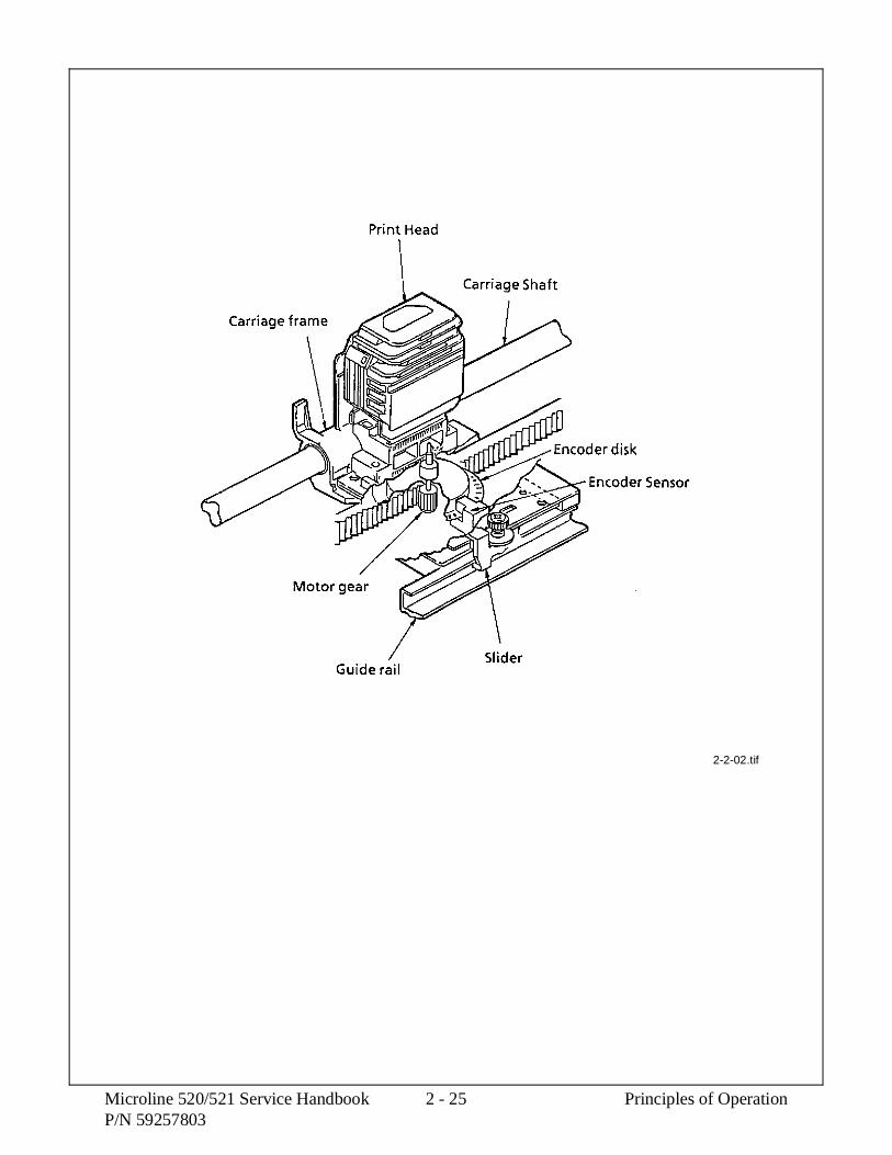
2-2-02.tif
Microline 520/521 Service Handbook 2 - 25 Principles of OperationP/N 59257803

2.2.03 Head Gap Mechanism
The head gap is automatically set for the thickness of the medium loaded in the printer. In thecase of envelopes, where the medium thickness varies as the printhead moves along the platen,the strike force of the pins changes to compensate for the differences in thickness.
Head Gap Setting Operation
Once printing starts, the space motor rotates the ribbon gear, causing idle gear C to turnthe change gear.
When the MPU requests a change in the head gap setting, the GAP-P signal causes thearmature (which is holding the change gear) to be attracted to the pranger magnet. Thegap reset spring can now push the change gear so it contacts the gap change gear.
The rotation of the gap change gear causes idle gear D to turn the adjust gear. The adjustgear turns the adjusting screw, resulting in a new head gap setting.
NOTE:
As the adjusting screw turns counter-clockwise, the gap narrows.
As the adjusting screw turns clockwise, the gap widens.
2-2-03a.tif
Principles of Operation 2 - 26 Microline 520/521 Service HandbookP/N 59257803

There is a cam at each setting of the gap change gear. When the change gear is at the topof the cam, the change gear disengages from the gap change gear. At this time, thearmature resets, changing the head gap by one setting.
The head gap is modified in .06 mm units for each range setting.
2-2-03b.tif
Microline 520/521 Service Handbook 2 - 27 Principles of OperationP/N 59257803

This page was intentionally left blank.
Principles of Operation 2 - 28 Microline 520/521 Service HandbookP/N 59257803

2.2.04 Ribbon Drive Mechanism
Ribbon Drive Operation
The ribbon drive mechanism feeds theribbon in synchronization with thespacing operation. The force requiredto drive the ribbon is obtained from thespace motor.
The ribbon drive mechanism iscomposed of the items listed below.
Ribbon Drive Gear Assembly
Ribbon Gear
This gear is located onthe space motor assembly
Ribbon Cartridge
A continuous loopribbon withuni-directional feed isused. Ink is suppliedfrom an ink tank, whichis built into the ribboncartridge.
When the space motor turns, the ribbongear on the spacing motor shaft rotates.The rotation is transmitted via acombination of gears, from the ribbondrive gear assembly to the drive gear inthe ribbon cartridge.
Although the space motor moves inboth the forward and reverse directionsduring bi-directional printing, the gearsin the ribbon drive assembly maintainuni-directional ribbon feed by switchingthe rotation direction of the gears.
2-2-04a.tif
Microline 520/521 Service Handbook 2 - 29 Principles of OperationP/N 59257803

2.2.05 Line Feed Mechanism
The line feed operation is accomplishedby activating the line feed motor whichturns the platen. The rotation of theplaten is used to feed paper from theselected paper path.
The components of the paper feedmechanism are listed below.
Line Feed Motor (pulse motor), withgears
Line Feed Idler Gear
Platen
Rear Tractor Feed Unit
Pressure Roller
Change Lever (Paper Path SelectionLever)
The change lever is used to select one ofthree different paper paths; top, rear orbottom.
Paper Clamp Mechanism
Moving the change lever between thebottom, top and rear positions, changesthe positions of the front release geararm and the release cam.
The movement of the front release geararm changes the position of the frontrelease gear shaft. This causes the frontpressure roller to open or close.
The movement of the release camcauses the rear pressure roller to open orclose.
Position of ChangeLever
Status of FrontPressure Roller
Tension of FrontPressure Roller
Status of RearPressure Roller
Tension of RearPressure Roller
Bottom OPEN N/A OPEN N/ATop CLOSED 250 g CLOSED 700 gRear CLOSED 90 g OPEN N/A
2-2-05A.tif
Principles of Operation 2 - 30 Microline 520/521 Service HandbookP/N 59257803

Cut Sheet/Continuous Sheet Switching Mechanism
Top Feed (for cut sheet paper)
When cut sheet paper is used during normal operation or by the Cut Sheet Feeder (CSF)option, place the change lever in the Top Feed position.
As the platen turns, the platen gear causes the idle gear to rotate.
At this time, the rear and front pressure rollers are pressed securely to the platen to feed thecut sheet.
The cut sheet detection lever enables the cut sheet detection switch (which is located on themain control board). This places the printer in the cut sheet mode.
When cut sheet paper is placed between the platen and the paper chute, the printerautomatically feeds the sheet to the print start position.
Rear/Bottom Feed (for continuous feed paper)
When the continuous feed paper is used, either with the rear tractor, optional bottom tractoror optional pull tractor, place the change lever in the Rear/Bottom Feed position.
When the change lever is placed in this position, the reset spring pushes the change gear. Inthis position, the idle gear is engaged with the bottom tractor unit drive gear and the tractorgear. As the platen turns, power is transferred from the platen gear, to the idle gear, to thechange gear, and then to the push tractor shaft.
CAUTION:
The cut sheet /continuous sensorlever must bepositioned below theBASW sensor. Thelever should contactthe sensor only whenthe change lever is inthe top feed (middle)setting.
If the lever is notcorrectly positioned,the ALARM lamp willlight and the unit willnot automatically loadpaper or receive data.
2-2-05b.tif
Microline 520/521 Service Handbook 2 - 31 Principles of OperationP/N 59257803

Cut Sheet Paper Feed Operation
As the line feed motor rotates, power istransferred through the deceleratinggears (line feed idler gear, platen gear)to the platen.
When using cut sheet paper, the changelever must be in the TOP position so theplaten and pressure rollers can feed thepaper. This also disengages the pushtractor.
Continuous Paper Feed (Rear TractorMechanism)
As the platen rotates, power istransferred to the tractor gear from theplaten gear, the idler gear, and thechange gear. The tractor gear drives thepin tractor belts, which feed thecontinuous paper.
Continuous Paper Feed (Pull TractorMechanism)
Bottom feed of continuous sheets ispossible only when an optional pulltractor unit is installed.
As the platen rotates, power istransferred to the drive gear from theline feed idler gear, the platen gear, idlergear B and idler gear A. The drive gearturns the pull tractor assembly, whichfeeds the continuous paper.
2-2-05c.tif
2-2-05d.tif
2-2-05e.tif
Principles of Operation 2 - 32 Microline 520/521 Service HandbookP/N 59257803

Continuous Paper Feed (Bottom TractorFeed Mechanism)
As the platen rotates, power istransferred to the drive gear from theplaten gear, the idle gear and the tractorchange gear. The drive gear turns thepin tractor belts on the bottom tractorfeed unit, which feeds the continuouspaper.
Continuous Paper Feed (Push/Pull Tractor Mechanism)
This mechanism consists of anoptional pull tractor and a standardpush tractor mechanism.
Continuous paper is fed by these twotractors at the same time.
2-2-05F.tif
2-2-05G.tif
Microline 520/521 Service Handbook 2 - 33 Principles of OperationP/N 59257803

2.2.06 Paper Detection Mechanism
Top Feed Paper Detection
When cut sheet paper is inserted into the printer, Point A of the Rear/Top Paper Feed Leveris pushed backward, causing the Sensor Lever to rotate.
As the Sensor Lever rotates, it contacts the Rear Sensor Lever. This makes the Rear SensorLever rotate.
The Rear Sensor Lever rotates, unblocking the Rear / Top Paper End Sensor (SNS1).
Rear Feed Detection
When paper is fed from the Rear Push Tractor, Point B is pushed backward. This makes theSensor Lever rotate.
As the Sensor Lever rotates, it contacts the Rear Sensor Lever. This makes the Rear SensorLever rotate.
The Rear Sensor Lever rotates, unblocking the Rear / Top Paper End Sensor (SNS1).
Bottom Feed Detection
When the paper is fed from the bottom of the printer, Point C is pushed, rotating the BottomPaper End Lever.
As the Bottom Paper End Leverrotates, it contacts the BottomSensor Lever. This makes theBottom Sensor Lever rotate.
The Bottom Sensor Leverrotates, unblocking the BottomPaper End Sensor (SNS2).
NOTE:
The method for detecting apaper-end condition is thereverse of the above.
PAPER-END is detectedwhen the Bottom Paper EndSensor (SNS2) is blocked.
2-39.tif
Principles of Operation 2 - 34 Microline 520/521 Service HandbookP/N 59257803

2.2.07 Support Protector Mechanism
During printer initialization, the support protector is latched in the stored position(approximately 5 mm from the left bracket of the main frame).
Just before paper is loaded, the printhead moves towards the left bracket and unlatchesthe support protector.
As the printhead moves to the right, the support protector reset spring pushes the supportprotector toward the center of the platen. With the support protector in this position, theribbon protector and the support protector prevent the leading edge of the paper fromcurling or folding.
Once the paper is ejected, the printhead slowly moves towards the left bracket.The support protector is latched in the stored position when it is pushed to approximately5 mm from the left bracket.
2-2-07.tif
Microline 520/521 Service Handbook 2 - 35 Principles of OperationP/N 59257803

2.2.08 Automatic Paper Load
The Microline 520/521 printers will automatically detect cut sheet paper and feed the paper tothe Top of Form (TOF) position.
Cut Sheet Paper
Set the change lever to the TOP FEED position.
NOTE:
When the change lever is in the TOP FEED position, the cut sheet detection levercontacts the cut sheet detection switch (BASW), which is located on the main controlboard.
Insert the sheet of paper between the platen and the paper chute.
Once paper is detected at the paper end sensor and the amount of time selected on theWait Time setting of the menu has lapsed, the line feed motor will feed the paper untilthe leading edge of the paper reaches the top of form position.
2-2-08a.tif
Principles of Operation 2 - 36 Microline 520/521 Service HandbookP/N 59257803

Continuous Feed Paper
Set the change lever to either the REAR FEED or BOTTOM FEED position.
NOTE:
When the change lever is in the REAR FEED or BOTTOM FEED position, the cut sheetdetection lever does NOT contact the cut sheet detection switch (BASW), which islocated on the main control board.
Place continuous feed paper in the appropriate tractor.
Press the FF/LOAD switch.
The line feed motor will feed the paper until the leading edge of the paper reaches the topof form position.
2-2-08b.tif
Microline 520/521 Service Handbook 2 - 37 Principles of OperationP/N 59257803

2.2.09 Paper Park
If continuous feed paper is installed and printing on cut sheet paper is desired, it is not necessaryto unload the continuous feed paper. The Paper Park feature provides a means of retracting thecontinuous feed paper from the paper path, while (at the same time) cut sheet paper is fed.
Paper Park Operation
Place the change lever in the REAR FEED or BOTTOM FEED position.
Press the PARK switch on the operation panel.
A reverse line feed operation retracts the paper until paper-end occurs or 19 inches ofpaper have been retracted.
NOTE:
Retracting 19 inches of paper without detecting a paper-end condition causes the linefeed operation to stop. The line feed operation stops because the printer assumes a jamhas occurred.
The operator can press the SEL switch to reset the ALARM LED and press the PARKswitch to continue the park operation.
This operation may be useful when length of the paper to be parked is greater than19 inches.
2-2-09.tif
Principles of Operation 2 - 38 Microline 520/521 Service HandbookP/N 59257803

SECTION THREE
MAINTENANCE

3.1 OVERVIEW
3.1.01 General Information
This section lists the parts replacement, adjustment, cleaning, lubrication, and shippingprocedures.
Disassembly should not be performed unless absolutely necessary. NEVER performdisassembly on a malfunctioning printer until you have followed the failure analysis proceduresin Section Four of this Service Handbook.
Follow the procedures listed in Adjustments and Service Settings. Adjustments may be requiredwhen either consumable or parts are replaced. Failure to perform these procedures could resultin unnecessary service calls.
Proper performance of maintenance and cleaning will help to achieve the best possible printquality from the printer.
3.1.02 Maintenance Tools
The following tools are required to service the printer.
#2 Phillips Screwdriver (with magnetic tip)
Straight-slot Screwdriver
Needle Nose Pliers (4 Inch)
Wire Cutters
Digital Multimeter
Feeler Gauge (capable of measuring .014 inches)
Shop Vacuum
Clean, soft, and lint-free Cloth
All-Purpose Cleaner
Contact Kleen (Okidata P/N 51802301)
Platen Cleaner
Machine Grease
Machine Oil
Microline 520/521 Service Handbook 3 - 1 MaintenanceP/N 59257803

3.1.03 Maintenance Precautions
1. Do not disassemble the unit if it is operating normally.
2. Before starting disassembly and assembly, always turn the AC power switch OFFand pull out the AC plug.
3. Detach the interface cable, if installed.
4. Do not remove parts unnecessarily. Try to keep disassembly to a minimum.
5. Use the recommended maintenance tools.
6. When disassembling, follow the listed sequence. Failure to follow the correctsequence may result in damaged parts.
7. Since screws, collars and other small parts are easily lost, they should be temporarilyattached to the original positions.
8. When handling circuit boards use extreme care. Integrated circuits (microprocessors,ROM, and RAM) can be destroyed by static electricity.
9. Do not place printed circuit boards directly on conductive surfaces.
10. Follow the recommended procedures when replacing assemblies and units.
11. Perform the printhead gap adjustment procedure (Refer to Section 3.3 of this ServiceHandbook) when the any of the following occur.
Print Quality is darker on one side of the document.
Parts are replaced
Printhead (3.2.02)
Space Motor Assembly (3.2.11)
Space Rack (3.2.13)
Guide Rail (3.2.15)
Platen Assembly (3.2.19)
Carriage Shaft (3.2.25)
Maintenance 3 - 2 Microline 520/521 Service HandbookP/N 59257803

3.2 DISASSEMBLY/ASSEMBLY PROCEDURES
General Information
This section contains the printer disassembly procedures. Only the removal procedures areexplained here. Reverse the procedure for the installation.
At the bottom of each procedure is a listing of the parts covered in that procedure. The Okidatapart number, item description, comment (RSPL, Option, Consumable) and cross-reference toAppendix B is provided for each part. Items included in the Recommended Spare Parts List areindicated by the acronym RSPL. N/A will appear where a part number is not available.
520 indicates that the item is specific to the Microline 520.
521 indicates that the item is specific to the Microline 521.
Both indicates that the item is common to both printers.
Part Item Comment Appendix BNumber Description Reference
This Service Handbook lists the disassembly procedures for major components of the unit.Okidata DOES NOT recommend disassembling a unit which is operating normally. If youdecide to perform disassembly during this training, Okidata recommends that you perform onlythe disassembly procedures for RSPL items. All other procedures are provided to assist you inidentifying parts. It is not likely that you will perform these procedures while servicing the unit.
Be sure to read all notes, cautions, and warnings, as they contain important informationregarding disassembly / assembly.
Microline 520/521 Service Handbook 3 - 3 MaintenanceP/N 59257803

3.2.01 Preliminary Items
1. Press the AC switch (1) and power off the printer.
2. Remove the paper, if installed (2).
3. Detach the AC power cord (3).
4. Detach the interface cable, if installed (4).
P/N 56609701 Cord: AC RSPL Both B.2.03
P/N 56624101 Cord: AC 220V (ML Series) Right Angle Option RSPL Both B.2.03
P/N 56624401 Cord: AC 240V Option RSPL Both B.2.08
P/N 70000803 Kit: Parallel Interface Option Both B.2.08Plug’n’Play Accessory
P/N 70012801 Kit: RS232-C Serial Interface Option Both B.2.08
Maintenance 3 - 4 Microline 520/521 Service HandbookP/N 59257803

1
2
4
3
3-2-01.pcx
Microline 520/521 Service Handbook 3 - 5 MaintenanceP/N 59257803

3.2.02 Printhead Assembly
1. Perform this procedure: 3.2.01.
2. Open the access cover (1).
3. Lift and remove the ribbon. (Not shown)
4. Pull the head clamp (2) towards the right and then rotate it up to release the printhead(3).
5. Pull the printhead straight up to remove it.
NOTE:
Installation
After installing the printhead, check the printhead gap adjustment. Refer to Section3.3 of this Service Handbook.
P/N 52107001 Ribbon: Black Consumable Both B.2.10
P/N 50707401 Clamp: Head RSPL Both B.2.07
P/N 50099501 Assembly: Printhead RSPL Both B.2.03
Maintenance 3 - 6 Microline 520/521 Service HandbookP/N 59257803

13
2
2
3
3-2-02.pcx
Microline 520/521 Service Handbook 3 - 7 MaintenanceP/N 59257803

3.2.03 Ribbon Protector
CAUTION
You MUST use a straight slot screwdriver to release the ribbon protector. If you attemptto lift the protector without releasing the tabs, the protector will break.
1. Perform these procedures: 3.2.01, and 3.2.02.
2. Open the pull-up roller cover (1).
3. Use a straight-slot screwdriver to release the extensions (2) from the carriage frameset (3).
4. Lift the ribbon protector (4) straight up and remove it.
P/N 53562801 Protector: Ribbon RSPL Both B.2.07
Maintenance 3 - 8 Microline 520/521 Service HandbookP/N 59257803

1
4
23
3-2-03.pcx
Microline 520/521 Service Handbook 3 - 9 MaintenanceP/N 59257803

3.2.04 Gear Case Assembly
1. Perform these procedures: 3.2.01, and 3.2.02.
2. Use a straight-slot screwdriver to release the four claws (1) of the gear case assembly(2).
3. Lift and remove the gear case assembly.
NOTE:
Lubrication
When lubricating, refer to Section 3.5 of this Service Handbook.
P/N 51228501 Gear: Case (Assembly) RSPL Both B.2.07
Maintenance 3 - 10 Microline 520/521 Service HandbookP/N 59257803

1
12
3-2-04.pcx
Microline 520/521 Service Handbook 3 - 11 MaintenanceP/N 59257803

3.2.05 Pull-up Roller Assembly
1. Perform this procedure: 3.2.01.
2. Open the access cover (1).
3. Open the cover of the pull-up roller assembly (2).
4. Press at A while rotating the assembly towards the back of the printer.
5. Remove the assembly.
NOTE:
Lubrication
When lubricating, refer to Section 3.5 of this Service Handbook.
P/N 53341501 Roller: Pull Up Assembly RSPL 520 B.2.05(Narrow)
P/N 53341601 Roller: Pull Up Assembly (Wide) RSPL 521 B.2.05
Maintenance 3 - 12 Microline 520/521 Service HandbookP/N 59257803

A
A
2
1
3-2-05.pcx
Microline 520/521 Service Handbook 3 - 13 MaintenanceP/N 59257803

3.2.06 Upper Cover, Access Cover, and Sheet Guide Assemblies
1. Perform this procedure: 3.2.01.
2. Pull the platen knob (1) straight out and remove it.
3. Set the change lever (2) to the bottom feed position (toward the rear of the printer).
4. Insert a flat-blade screwdriver into the grooves (3) of the frame and pry the uppercover (4) away from the frame.
5. Raise the front side of the upper cover assembly.
6. Tilt the upper cover assembly toward the rear to disengage the claws (not shown) atthe rear of the frame.
7. Lift the upper cover assembly and remove it.
CAUTION:
Do not rotate the access cover past the vertical when removing it or you will break thetab extensions.
8. Raise the access cover assembly (5) until it is vertical, then lift it straight up toremove it.
9. Remove the sheet guide assembly (6).
10. Note the position of the cover (B) [for card slot] (7). This is part of the upper coverand should not be removed. No font cards are currently available.
CAUTION:
When installing the upper cover, make sure that the sensors correctly contact the controlboard (3.2.07). The cut sheet/continuous sensor lever must be positioned below theBASW sensor. The lever should contact the sensor only when the change lever is in thetop feed (middle) setting. If the lever is not correctly positioned, the ALARM lamp willlight and the unit will not automatically load paper or receive data.
When cleaning, refer to Section 3.4 of this Service Handbook.
P/N 51009401 Guide: Sheet (Narrow) RSPL 520 B.2.02
P/N 51009501 Guide: Sheet (Wide) RSPL 521 B.2.02
P/N 53066902 Cover: Upper (Narrow) RSPL 520 B.2.02
P/N 53067002 Cover: Upper (Wide) RSPL 521 B.2.02
P/N 53067101 Cover: Access (Narrow) RSPL 520 B.2.02
P/N 53067201 Cover: Access (Wide) RSPL 521 B.2.02
P/N 53067301 Cover: (B) for card slot RSPL Both B.2.03
P/N 53562601 Knob: Platen (ML500 Series) RSPL Both B.2.03
Maintenance 3 - 14 Microline 520/521 Service HandbookP/N 59257803

3
2
4
56
17
3-2-06.pcx
Microline 520/521 Service Handbook 3 - 15 MaintenanceP/N 59257803

3.2.07 Control Board (FJIM)
1. Perform these procedures: 3.2.01, and 3.2.06.
2. Remove the two screws (1).
3. Release the control board (2) from the bracket (3).
4. Tilt the board to access the connectors.
5. Detach connectors CN6 - operator panel (4), CN7- carriage cable (5), CN3 - powersupply (6), and CN5 - line feed motor (7).
6. Remove the board.
NOTE:
Installation
The bottom sensor lever must be positioned in the SNS3 sensor (8).
The rear sensor lever must be positioned in the SNS1 sensor (9).
The cut sheet/continuous sensor lever must be positioned below the BASW sensor(10). The lever should contact the sensor only when the change lever is in the topfeed (middle) setting.
If the lever is not correctly positioned, the ALARM lamp will light and the unit willnot automatically load paper or receive data.
The IC: EEPROM is soldered in on the board.
P/N 55072401 PCB: FJIM (w/o ROM) RSPL Both B.2.03
P/N 55938301 IC: EEPROM BR93CC46A RSPL Both B.2.03
Maintenance 3 - 16 Microline 520/521 Service HandbookP/N 59257803

3
21
6
7
8
5
49
10
3-2-07.pcx
Microline 520/521 Service Handbook 3 - 17 MaintenanceP/N 59257803
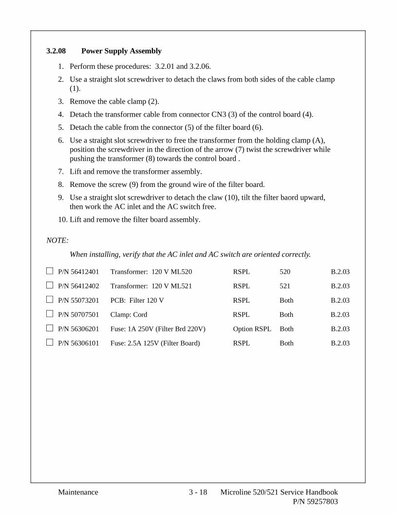
3.2.08 Power Supply Assembly
1. Perform these procedures: 3.2.01 and 3.2.06.
2. Use a straight slot screwdriver to detach the claws from both sides of the cable clamp(1).
3. Remove the cable clamp (2).
4. Detach the transformer cable from connector CN3 (3) of the control board (4).
5. Detach the cable from the connector (5) of the filter board (6).
6. Use a straight slot screwdriver to free the transformer from the holding clamp (A),position the screwdriver in the direction of the arrow (7) twist the screwdriver whilepushing the transformer (8) towards the control board .
7. Lift and remove the transformer assembly.
8. Remove the screw (9) from the ground wire of the filter board.
9. Use a straight slot screwdriver to detach the claw (10), tilt the filter baord upward,then work the AC inlet and the AC switch free.
10. Lift and remove the filter board assembly.
NOTE:
When installing, verify that the AC inlet and AC switch are oriented correctly.
P/N 56412401 Transformer: 120 V ML520 RSPL 520 B.2.03
P/N 56412402 Transformer: 120 V ML521 RSPL 521 B.2.03
P/N 55073201 PCB: Filter 120 V RSPL Both B.2.03
P/N 50707501 Clamp: Cord RSPL Both B.2.03
P/N 56306201 Fuse: 1A 250V (Filter Brd 220V) Option RSPL Both B.2.03
P/N 56306101 Fuse: 2.5A 125V (Filter Board) RSPL Both B.2.03
Maintenance 3 - 18 Microline 520/521 Service HandbookP/N 59257803

4
AC Inlet
AC Switch
3
6
7
8
5
1
2
A
9
10
3-2-08.pcx
Microline 520/521 Service Handbook 3 - 19 MaintenanceP/N 59257803

3.2.09 Operator Panel PCB (LEOP)
1. Perform these procedures: 3.2.01, 3.2.06. and 3.2.07.
2. Cut the nylon tie and release the cable. (Not shown)
3. Disengage the claws (1) on both sides of the frame.
4. Lift the operator panel assembly (2) straight up and remove it.
5. Open eight claws (3) and remove the operator panel board (4) from the operatorpanel (5).
P/N 53562703 Panel: Operator RSPL Both B.2.03
P/N 55937502 PCB: LEOP (Operator Panel) RSPL Both B.2.03
Maintenance 3 - 20 Microline 520/521 Service HandbookP/N 59257803

4
5
3
3
3
32
1
1
3-2-09.pcx
Microline 520/521 Service Handbook 3 - 21 MaintenanceP/N 59257803

3.2.10 PC Connector
1. Perform these procedures: 3.2.01, 3.2.02, and 3.2.04.
2. Remove the two screws (1) and the connector holders. The holders are not shown.
3. Remove the PC connector (2).
NOTE:
Installation
Do not touch the contacts of the PC connector.
Do not touch the contacts of the space motor (3).
Cleaning
When cleaning, refer to Section 3.4 of this Service Handbook.
P/N 56729601 Connector: PC HD40 RSPL Both B.2.07
Maintenance 3 - 22 Microline 520/521 Service HandbookP/N 59257803

3
2
1
3-2-10.pcx
Microline 520/521 Service Handbook 3 - 23 MaintenanceP/N 59257803

3.2.11 Space Motor and Roller Guide Assemblies
1. Perform these procedures: 3.2.01, 3.2.02, 3.2.04, and 3.2.10.
2. Remove the three screws (1).
3. Lift the space motor assembly (2).
4. Remove the left (3) and right connector holders (4).
5. Remove the roller guide assembly (5) and guide roller spring (6).
6. Use firm pressure to pull the carriage cable (7) out to detach the cable from the spacemotor assembly.
7. Remove the space motor assembly.
NOTE:
The guide roller assembly includes the guide roller (8), the guide roller holder (9), andthe pin (10).
Installation: Position the guide roller assembly first.
The contact side of the cable faces down when the carriage cable is inserted into theconnector on the space motor assembly. Work the cable from side to side until it is fullyseated in the connector. No contacts should be visible.
After installing the space motor assembly, check the printhead gap adjustment. Refer toSection 3.3 of this Service Handbook.
When lubricating, refer to Section 3.5 of this Service Handbook.
P/N 53343001 Holder: Connector (L) RSPL Both B.2.07
P/N 53343101 Holder: Connector (R) RSPL Both B.2.07
P/N 56510401 Motor: Space Assembly RSPL Both B.2.07
P/N 53343301 Guide: Roller Assembly Both B.2.07
P/N 53341901 Roller: Guide RSPL Both B.2.07
P/N 53342001 Holder: Guide Roller RSPL Both B.2.07
P/N N/A Pin Both B.2.07
P/N N/A Guide Roller Spring Both B.2.07
Maintenance 3 - 24 Microline 520/521 Service HandbookP/N 59257803

1
2
5
7
1
6
89
10
4
3
3-2-11.pcx
Microline 520/521 Service Handbook 3 - 25 MaintenanceP/N 59257803

3.2.12 Carriage Cable
1. Perform these procedures: 3.2.01, 3.2.06, 3.2.07, and 3.2.11.
2. Slightly bow the carriage cable (1) to release it from the claws (2) and the projectionon the main frame (3).
3. Remove the carriage cable guide (4).
4. Remove the carriage cable.
NOTE:
Installation
The contacts on the cable face up when the cable is positioned on the main frame.
The cable end with the 45° angled contacts connects to the gear case assembly.
Do NOT sharply bend the carriage cable. You will slightly bow the cable to positionit under the claws and over the projection.
P/N 56627301 Cable: Carriage (Narrow) RSPL 520 B.2.07
P/N 56627302 Cable: Carriage (Wide) RSPL 521 B.2.07
Maintenance 3 - 26 Microline 520/521 Service HandbookP/N 59257803

32
1
4
3-2-12.pcx
Microline 520/521 Service Handbook 3 - 27 MaintenanceP/N 59257803

3.2.13 Space Rack
1. Perform these procedures: 3.2.01, 3.2.02, 3.2.04, 3.2.10, and 3.2.11.
2. Remove the spring (1).
3. Disengage the claws (2) on the both ends of the space rack (3).
4. Pull the space rack straight up and remove it.
NOTE:
Installation
After installing the space rack, check the printhead gap adjustment. Refer to Section3.3 of this Service Handbook.
Cleaning
When cleaning, refer to Section 3.4 of this Service Handbook.
CAUTION
Do NOT lubricate the space rack. Lubricating the space rack will attract dust. Ifenough dust accumulates on the space rack, printing problems will occur.
P/N 50923501 Spring: Tension (Space Rack) RSPL Both B.2.04
P/N 53563301 Rack: Space (Narrow) RSPL 520 B.2.04
P/N 53563401 Rack: Space (Wide) RSPL 521 B.2.04
Maintenance 3 - 28 Microline 520/521 Service HandbookP/N 59257803

2
3
1
2
3-2-13.pcx
Microline 520/521 Service Handbook 3 - 29 MaintenanceP/N 59257803

3.2.14 Roller/Holder Backup Assembly
1. Perform these procedures: 3.2.01, 3.2.02, 3.2.04, 3.2.10, and 3.2.11.
2. Use a small straight slot screwdriver to disengage the claws of the backup rollerholder spring (1) from the carriage frame (2).
3. Remove the roller/holder backup assembly (3).
NOTE:
The roller/holder backup assembly includes the backup roller (4), the backup rollerholder (5), and the pin (6).
P/N 53343201 Assembly: Roller/Holder Backup Both B.2.07
P/N 53341701 Roller: Back Up RSPL Both B.2.07
P/N 53341801 Holder: Back Up Roller RSPL Both B.2.07
P/N N/A Pin Both B.2.07
P/N 50925001 Backup Roller Holder Spring Both B.2.07
Maintenance 3 - 30 Microline 520/521 Service HandbookP/N 59257803

3
1
2
6
54
3-2-14.pcx
Microline 520/521 Service Handbook 3 - 31 MaintenanceP/N 59257803

3.2.15 Guide Rail and Adjust Cam
1. Perform these procedures: 3.2.01, 3.2.02, 3.2.04, 3.2.10, 3.2.11, and 3.2.14.
2. Rotate the adjust cam (1) in the direction of arrow A as far as possible.
3. Pull the cam out and remove it.
4. Carefully press the claw (2 location only) in the base frame down to release the guiderail (3). Do not press too hard or the claw will break.
5. Use a straight slot screwdriver to slide the guide rail in direction of arrow A.
6. Lift the guide at position B and work the other end of the guide free to remove theguide rail.
7. Remove the ground clip (4)
NOTE:
Installation
After installing the guide rail, check the printhead gap adjustment. Refer to Section3.3 of this Service Handbook.
P/N 51009701 Guide: Rail Ground Clip RSPL Both B.2.04
P/N 51009801 Guide: Rail (Narrow) RSPL 520 B.2.04
P/N 51009901 Guide: Rail (Wide) RSPL 521 B.2.04
P/N 53067701 Cam: Adjust RSPL Both B.2.04
Maintenance 3 - 32 Microline 520/521 Service HandbookP/N 59257803

1
4
3
B
A
2
3-2-15.pcx
Microline 520/521 Service Handbook 3 - 33 MaintenanceP/N 59257803

3.2.16 Left Ground Plate
1. Perform these procedures: 3.2.01, 3.2.06, and 3.2.07.
2. Cut the nylon tie and release the cable. (Not shown).
3. Work the left ground plate (1) up, and then out, to remove it.
P/N 51010301 Plate: Left Ground RSPL Both B.2.04
Maintenance 3 - 34 Microline 520/521 Service HandbookP/N 59257803
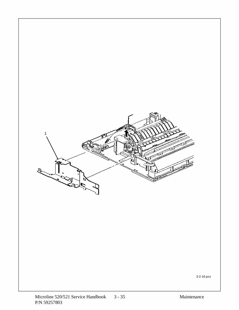
1
3-2-16.pcx
Microline 520/521 Service Handbook 3 - 35 MaintenanceP/N 59257803

3.2.17 Right Ground Plate
1. Perform these procedures: 3.2.01, and 3.2.06.
2. Pull the top tabs (1) of the right ground plate (2) out to free the plate from the clawsof the base frame. You may have to use a screwdriver to work the plate tabs free.
3. Lift the plate and remove it.
NOTE:
Installation
The plate must be securely seated under the claws.
P/N 51010201 Plate: Right Ground RSPL Both B.2.05
Maintenance 3 - 36 Microline 520/521 Service HandbookP/N 59257803

1
2
3-2-17.pcx
Microline 520/521 Service Handbook 3 - 37 MaintenanceP/N 59257803

3.2.18 Rear and Cut Sheet Paper Feed Sensor Levers
1. Perform these procedures: 3.2.01, 3.2.06, 3.2.07, 3.2.16, and 3.2.20.
2. Turn the cut sheet/continuous feed paper sensor lever (1) until the flag is at the top,then work the lever free.
3. Remove the lever.
4. Turn the rear feed paper sensor lever (2) until the flag is at the top, then work thelever free.
5. Remove the lever.
P/N 50804902 Lever: Sensor RSPL Both B.2.04Cut Sheet/Continuous
P/N 50804801 Lever: Rear Sensor RSPL Both B.2.04
Maintenance 3 - 38 Microline 520/521 Service HandbookP/N 59257803

2
1
3-2-15.pcx
Microline 520/521 Service Handbook 3 - 39 MaintenanceP/N 59257803

3.2.19 Platen Assembly
1. Perform these procedures: 3.2.01, and 3.2.06.
2. Move the change lever (1) to the bottom feed position (to the rear of the printer).
3. Push the lock levers (2) in, then rotate them towards the front to unlock them fromthe frame.
4. The levers should be vertical.
5. Lift the platen assembly (3) straight up and remove it.
NOTE:
Installation
After installing the platen assembly, check the printhead gap adjustment. Refer toSection 3.3 of this Service Handbook.
Cleaning
When cleaning, refer to Section 3.4 of this Service Handbook.
Lubrication
When lubricating, refer to Section 3.5 of this Service Handbook.
P/N 50098301 Platen Assembly (Narrow) RSPL 520 B.2.05
P/N 50098302 Platen Assembly (Wide) RSPL 521 B.2.05
Maintenance 3 - 40 Microline 520/521 Service HandbookP/N 59257803

1
2
3
2
3-2-19.pcx
Microline 520/521 Service Handbook 3 - 41 MaintenanceP/N 59257803

3.2.20 Paper Chute Assembly
1. Perform these procedures: 3.2.01, 3.2.06, and 3.2.19.
2. Remove the rear pressure roller (1).
3. Use a straight slot screwdriver to release the claws of the lock spring (2) and removethe spring.
4. Remove the paper chute assembly (3).
NOTE:
The paper chute assembly includes the levers for the rear and top paper feed paths.
P/N 53341301 Roller: Pressure Rear (Narrow) RSPL 520 B.2.06
P/N 53341401 Roller: Pressure Rear (Wide) RSPL 521 B.2.06
P/N 50924701 Spring: Lock RSPL Both B.2.06
P/N 50097701 Paper Chute Assembly N RSPL 520 B.2.06
P/N 50097801 Paper Chute Assembly W RSPL 521 B.2.06
Maintenance 3 - 42 Microline 520/521 Service HandbookP/N 59257803

2
1
3
3-2-15.pcx
Microline 520/521 Service Handbook 3 - 43 MaintenanceP/N 59257803

3.2.21 Line Feed Motor Assembly
1. Perform these procedures: 3.2.01, 3.2.06, 3.2.07, 3.2.16, 3.2.19, 3.2.20, and 3.2.21.
2. Firmly press down on the line feed motor assembly (1) while tilting the assembly out.
3. Remove the line feed motor assembly.
4. Remove the line feed connection cord (2).
CAUTION:
The line feed idle gear (3) should be removed only if it must be replaced. The claws willbreak when the gear is removed. A new gear must be installed.
P/N 51228401 Gear: Line Feed Idle RSPL Both B.2.04
P/N 56510301 Motor: Line Feed (Assembly) RSPL Both B.2.04
P/N 56627201 Cord: Connection Line Feed RSPL Both B.2.04
Maintenance 3 - 44 Microline 520/521 Service HandbookP/N 59257803

1
3
2
3-2-21.pcx
Microline 520/521 Service Handbook 3 - 45 MaintenanceP/N 59257803

3.2.22 Reset Spring
CAUTION:
Please read through this entire procedure before performing it.
Do not press against the vertical extensions of the reset spring at any time during thisprocedure.
Firm pressure will release the spring, not brute force.
1. Perform these procedures: 3.2.01, 3.2.06, and 3.2.17.
2. Place the right side of the unit over the edge of your work surface. You must be ableto access the bottom of the unit. You will be working underneath and above the resetspring (1) at the same time.
3. Reach from underneath the unit and press up at the extension (A) to free the springfrom the claw.
4. While pressing up, slide the spring out (in the direction of Arrow B) and remove it.
P/N 50923201 Spring: Reset RSPL Both B.2.05
Maintenance 3 - 46 Microline 520/521 Service HandbookP/N 59257803

A
B
1
3-2-22.pcx
Microline 520/521 Service Handbook 3 - 47 MaintenanceP/N 59257803

3.2.23 Idle Gear and Change Lever
1. Perform these procedures: 3.2.01, 3.2.06, 3.2.07, 3.2.16, 3.2.17, 3.2.19, 3.2.20, and3.2.22.
2. Remove the idle gear (1). The idle gear is a large narrow gear.
3. Release the claw (2) of the change lever (3). The claw is accessed from inside theunit.
4. Remove the change lever.
NOTE:
Lubrication
When lubricating, refer to Section 3.5 of this Service Handbook.
P/N 50805101 Lever: Change RSPL Both B.2.05
P/N 51228201 Gear: Idle RSPL Both B.2.05
Maintenance 3 - 48 Microline 520/521 Service HandbookP/N 59257803

1
3
2
12 3
3-2-23.pcx
Microline 520/521 Service Handbook 3 - 49 MaintenanceP/N 59257803

3.2.24 Pressure Spring
1. Perform these procedures: 3.2.01, 3.2.06, 3.2.07, 3.2.16, 3.2.17, 3.2.19, 3.2.20,3.2.22, and 3.2.23.
2. Turn the front release gear arm (1) until it is disengaged.
3. Remove the release cam (2). This is the medium size, thick cam.
4. Work the end of the pressure spring (3) free and remove the spring.
5. Remove the front release gear arm. This arm is long, with a serrated edge.
6. Remove the switch lever (4). This is the small lever.
NOTE:
Installation
Install the release cam first.
Then, install one end of the pressure spring into the release cam.
Slide the cam and spring away from the base frame until the opposite end of thespring can be installed into the frame.
Make sure that the front release gear arm is engaged as shown (A).
Lubrication
When lubricating, refer to Section 3.5 of this Service Handbook.
P/N 50805201 Lever: Switch RSPL Both B.2.06
P/N 50805301 Cam: Release RSPL Both B.2.05
P/N 50923301 Spring: Pressure (Narrow) RSPL 520 B.2.06
P/N 50923401 Spring: Pressure (Wide) RSPL 521 B.2.06
P/N 51228301 Arm: Front Release Gear RSPL Both B.2.06
Maintenance 3 - 50 Microline 520/521 Service HandbookP/N 59257803

23
4
1
A
1
Front Release Gear Shaft
3-2-24.pcx
Microline 520/521 Service Handbook 3 - 51 MaintenanceP/N 59257803

3.2.25 Carriage Shaft
CAUTION
The space motor assembly, etc. may be left in place when removing the carriage shaft.However, use extra care when doing so.
The carriage cable should be detached from the space motor before removing thecarriage shaft.
1. Perform these procedures: 3.2.01, 3.2.06, 3.2.07, and 3.2.16.
2. Push the end (A) of the carriage shaft (1) until it clears the base frame.
3. Pull the carriage shaft free of the base frame.
4. Remove the support protect reset spring (2).
5. Remove the support protector assembly (3).
6. Remove the frame set carriage (4).
NOTE:
Installation
After installing the carriage shaft, check the printhead gap adjustment. Refer toSection 3.3 of this Service Handbook.
Cleaning
When cleaning, refer to Section 3.4 of this Service Handbook.
Lubrication
When lubricating, refer to Section 3.5 of this Service Handbook.
P/N 50098901 Carriage: Frame Set RSPL Both B.2.07
P/N 50923601 Spring: Support Protect Reset RSPL Both B.2.04
P/N 53067601 Protector: Support (Assembly) RSPL Both B.2.04
P/N 53563501 Shaft: Carriage (Narrow) RSPL 520 B.2.04
P/N 53563502 Shaft: Carriage (Wide) RSPL 521 B.2.04
Maintenance 3 - 52 Microline 520/521 Service HandbookP/N 59257803

1
3
2
A
4
3-2-15.pcx
Microline 520/521 Service Handbook 3 - 53 MaintenanceP/N 59257803

3.2.26 Leaf Spring
1. Perform these procedures: 3.2.01, 3.2.06, 3.2.07, 3.2.16, and 3.2.25.
2. Position the unit so you can access the top and bottom of the leaf spring (1).
3. Start at one end of the spring.
4. Use a straight slot screwdriver to release the bottom extension (2) from the claw ofthe base frame.
5. Pull the spring up to release the top of the spring from the upper claw.
6. Repeat the above two steps, working towards the opposite end of the spring.
7. Remove the spring.
P/N 50923001 Spring: Leaf (Narrow) RSPL 520 B.2.04
P/N 50923101 Spring: Leaf (Wide) RSPL 521 B.2.04
Maintenance 3 - 54 Microline 520/521 Service HandbookP/N 59257803

2
1
3-2-15.pcx
Microline 520/521 Service Handbook 3 - 55 MaintenanceP/N 59257803

3.2.27 Bottom Paper Sensor Levers
1. Perform these procedures: 3.2.01, 3.2.06, 3.2.07, 3.2.16, 3.2.17, 3.2.19, 3.2.20,3.2.22, 3.2.23, and 3.2.24.
2. Working from the underside of the unit, release the claws of the paper pan (1). Whenyou release a claw, push on the claw to move the paper pan away from the mainframe.
3. Remove the pan.
4. Rotate the bottom sensor lever (2) until the flag is at the top. Then, lift the lever andwork it free of the frame to remove it. This lever has a box end.
5. Remove the bottom paper end lever (3).
6. Work the front release gear shaft (4) free of the tabs and remove it.
NOTE:
Lubrication
When lubricating, refer to Section 3.5 of this Service Handbook.
P/N 50097301 Pan: Paper (Narrow) RSPL 520 B.2.06
P/N 50097401 Pan: Paper (Wide) RSPL 521 B.2.06
P/N 50804601 Lever: Bottom Paper End RSPL Both B.2.04
P/N 50804701 Lever: Bottom Sensor RSPL Both B.2.04
P/N 51227801 Shaft: Front Release Gear RSPL 520 B.2.06(Narrow)
P/N 51227901 Shaft: Front Release Gear (Wide) RSPL 521 B.2.06
Maintenance 3 - 56 Microline 520/521 Service HandbookP/N 59257803

1
4
2
3
3-2-15.pcx
Microline 520/521 Service Handbook 3 - 57 MaintenanceP/N 59257803
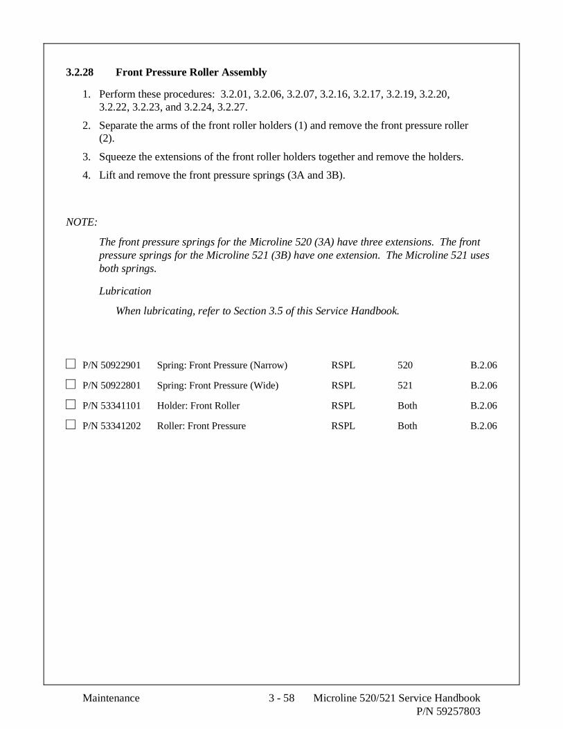
3.2.28 Front Pressure Roller Assembly
1. Perform these procedures: 3.2.01, 3.2.06, 3.2.07, 3.2.16, 3.2.17, 3.2.19, 3.2.20,3.2.22, 3.2.23, and 3.2.24, 3.2.27.
2. Separate the arms of the front roller holders (1) and remove the front pressure roller(2).
3. Squeeze the extensions of the front roller holders together and remove the holders.
4. Lift and remove the front pressure springs (3A and 3B).
NOTE:
The front pressure springs for the Microline 520 (3A) have three extensions. The frontpressure springs for the Microline 521 (3B) have one extension. The Microline 521 usesboth springs.
Lubrication
When lubricating, refer to Section 3.5 of this Service Handbook.
P/N 50922901 Spring: Front Pressure (Narrow) RSPL 520 B.2.06
P/N 50922801 Spring: Front Pressure (Wide) RSPL 521 B.2.06
P/N 53341101 Holder: Front Roller RSPL Both B.2.06
P/N 53341202 Roller: Front Pressure RSPL Both B.2.06
Maintenance 3 - 58 Microline 520/521 Service HandbookP/N 59257803

2
3A3B
1
3-2-15.pcx
Microline 520/521 Service Handbook 3 - 59 MaintenanceP/N 59257803

3.2.29 Tractor Assembly
1. Perform these procedures: 3.2.01, 3.2.06, 3.2.07, 3.2.16, 3.2.17, 3.2.19, 3.2.20,3.2.22, 3.2.23, and 3.2.24.
2. Use a needle nose pliers to release the claw of the tractor gear (1) and remove thegear.
3. Remove the change gear (2).
4. Raise the lock levers (3) on the left (4) and right (5) tractor assemblies.
5. Slide the lower tractor feed shaft (6) in the direction of arrow A and remove the shaft.This shaft is square.
6. Slide the upper tractor feed shaft (7) in the direction of arrow A and remove the shaft.This shaft is round.
7. Remove the left tractor assembly, the guide (8), and the right tractor assembly.
NOTE:
Installation
The tractors must be synchronized. Align the synchronization marks (9) in the samedirection.
Verify that the guide holes (10) in the tractor drive gears are facing the samedirection.
The left tractor assembly must be positioned to the left (line feed motor side) of theplastic tab and ground plate.
Lubrication
When lubricating, refer to Section 3.5 of this Service Handbook.
P/N 50097501 Tractor: Assembly (Narrow) RSPL 520 B.2.06
P/N 50097502 Tractor: Assembly (Wide) RSPL 521 B.2.06
P/N 51228001 Gear: Change RSPL Both B.2.05
P/N 51228101 Gear: Tractor RSPL Both B.2.05
Maintenance 3 - 60 Microline 520/521 Service HandbookP/N 59257803

3
47
8
5
3
6
1
1
A
10
9
9
2
3-2-29.pcx
Microline 520/521 Service Handbook 3 - 61 MaintenanceP/N 59257803

3.2.30 Main Frame
1. All disassembly procedures must be carried out to reach the base frame (1).
P/N 53563101 Frame: Main (Narrow) RSPL 520 B.2.04/5/6
P/N 53563201 Frame: Main (Wide) RSPL 521 B.2.04/5/6
Maintenance 3 - 62 Microline 520/521 Service HandbookP/N 59257803

1
3-2-15.pcx
Microline 520/521 Service Handbook 3 - 63 MaintenanceP/N 59257803

This page was intentionally left blank.
Maintenance 3 - 64 Microline 520/521 Service HandbookP/N 59257803

3.3 PRINTER ADJUSTMENTS
3.3.01 General Information
This section contains the procedures for performing adjustments on the printer. Theseprocedures may be required when replacing either consumables or parts. Thedisassembly/assembly procedures list the required adjustments and refer you to this section.Failure to perform these procedures may result in unnecessary service calls.
Microline 520/521 Service Handbook 3 - 65 MaintenanceP/N 59257803

3.3.02 Printhead Gap Adjustment
General Information
Before performing this adjustment, always verify that the printhead is properly installed. Thisadjustment should be performed when the following parts are replaced.
1. Printhead (3.2.02)
2. Space Motor Assembly (3.2.11)
3. Space Rack (3.2.13)
4. Guide Rail (3.2.15)
5. Platen Assembly (3.2.19)
6. Carriage Shaft (3.2.25)
NOTE:
Place a new ribbon cartridge in the printer before testing for parallelism.
If the density of the top portion of the characters differ from that of the bottom portion,follow steps 10 - 12.
Maintenance 3 - 66 Microline 520/521 Service HandbookP/N 59257803

This adjustment is comprised of four phases.
1. Setup Phase
Steps 1-5
The cover is removed and the printhead is placed at a known reference point.
2. Printhead Gap Modification Phase
Steps 6 - 10
The distance between the printhead and the platen (at the left side of theplaten) is modified by turning the adjust screw which varies the verticalposition of the space motor.
3. Parallel Adjustment Phase
Steps 11 - 12
The adjust cam lever is moved to ensure the printhead moves parallel to theplaten.
4. Verification Phase
Steps 13 -14
Verifies that the parallel adjustment phase did not affect the printhead gapmodification phase.
Microline 520/521 Service Handbook 3 - 67 MaintenanceP/N 59257803

Procedure
Setup Phase
1. Remove the upper cover and pull roller assembly.
2. Move the change lever to the rear paper feed position.
3. Rotate the platen.
4. Set the gap change gear (Figure 1 A) to Range 2 by turning the adjust screw using asmall phillips screwdriver. Turn this screw slowly while moving the carriage (1) tothe left (if turning the screw counter clockwise) or (2) to the right (if turning thescrew clockwise). This will allow easier rotation of the gears and prevent the gearsfrom being stripped.
DO NOT DISENGAGE THE ADJUST GEAR!5. Remove the ribbon protector.
Printhead Gap Modification Phase
6. Slide the carriage assembly to the left side of the platen.
7. Check the printhead gap. Use a 0.014 inch or 0.35 mm feeler gauge. The printheadgap must measure 0.014 +/- 0.001 inch (0.35 +/- 0.03 mm).
8. Use a large, straightened paper clip (Figure 1 B) to push down on the adjust gear.This will disengage the adjust gear from idle gear D.
9. Use a small phillips screwdriver to turn the adjust screw. (Figure 1 C)
Turning the screw CLOCKWISE will increase the printhead gap.
Turning the screw COUNTERCLOCKWISE will decrease the gap.
10. Slide the carriage assembly to the right side of the platen.
Parallel Adjustment Phase
11. Check the printhead gap at the right side of the platen.
12. If the gap measurements are different between the left and right positions, turn theadjust cam as follows. (Figure 2 B)
Turning the cam CLOCKWISE will increase the printhead gap.
Turning the cam COUNTERCLOCKWISE will decrease the printhead gap.
Verification Phase
13. Check the printhead gap adjustment at the left, right, and center of the platen.
14. If the printhead gap is not the same at all three positions, return to step 6.
Maintenance 3 - 68 Microline 520/521 Service HandbookP/N 59257803

Figure 2
A
B
Figure 1
A
B
C
3-3-01a.tif
Microline 520/521 Service Handbook 3 - 69 MaintenanceP/N 59257803

3.3.03 Key Combinations
Key Combinations DescriptionSEL + LF(Hold during Power-ON)
Reset Menu to Factory Defaults.
SEL(Hold during Power-ON)
Access Menu (if Menu set to LIMITED OPERATION)
QUIET + FF/LOAD(Hold during Power-ON)
Reset Top of Form to Factory Default (1 inch)
QUIET(Hold during Power-ON)
Activate Rolling ASCII Test
LF(Hold during Power-ON)
Activate Font Test
SEL + FF/LOAD(Hold during Power-ON)
Activate Hexadecimal Dump Test
Maintenance 3 - 70 Microline 520/521 Service HandbookP/N 59257803

3.3.04 Menu Operation
General Information
The menu is used to customize the printer’s settings and features.
The Menu is made up of a number of Groups.
Each Group has a list of Items.
Each Item has several Settings.
Menu Mode
To place the printer in the Menu Mode, follow this procedure.
1. Verify that continuous feed paper is installed.
2. Verify that the ribbon is correctly installed.
3. Verify that the width of the installed paper matches the paper width menu setting.
CAUTION:
If the Menu is set for wide paper, and narrow paper is used, the printhead will print onthe platen. This could damage / destroy the printhead, platen, and ribbon.
4. Press and hold the SHIFT switch while pressing the SEL switch.
5. The MENU lamp will light. If the printer was selected, the SELECT lamp will light.
When in Menu Mode, the functions printed below the operator panel switches are active.
6. Press GROUP until the desired Group prints.
7. Press ITEM until the desired Item prints.
8. Press SET until the desired Setting prints.
9. Press EXIT to save the change and exit Menu Mode.
Microline 520/521 Service Handbook 3 - 71 MaintenanceP/N 59257803

Printing the Menu
Printing the Menu provides a reference of current menu settings.
This will help you move through the menu.
Okidata STRONGLY RECOMMENDS printing the Menu before resetting the Menu to factorydefaults.
Once the Menu is reset, all customized settings are LOST.
To print the Menu, follow this procedure.
1. Verify that continuous feed paper is installed.
2. Verify that the ribbon is correctly installed.
3. Verify that the width of the installed paper matches the paper width menu setting.
CAUTION:
If the Menu is set for wide paper, and narrow paper is used, the printhead will print onthe platen. This could damage / destroy the printhead, platen, and ribbon.
4. Press and hold the SHIFT switch while pressing the SEL switch.
5. The MENU lamp will light. If the printer was selected, the SELECT lamp will light.
When in Menu Mode, the functions printed below the operator panel switches are active.
6. Press the PRINT switch.
7. The Menu will print.
8. Press EXIT to exit Menu Mode.
For more information regarding the menu, please refer to the Printer Handbook.
Maintenance 3 - 72 Microline 520/521 Service HandbookP/N 59257803

Sample Menu
3-3-06.tif
Microline 520/521 Service Handbook 3 - 73 MaintenanceP/N 59257803

This page was intentionally left blank.
Maintenance 3 - 74 Microline 520/521 Service HandbookP/N 59257803

Reset Menu to Factory Defaults
CAUTION:
Once the menu has been reset, all customized menu settings will be lost.
Always print the menu before resetting the printer to factory defaults.
To reset the menu to factory default settings:
1. Before resetting the Menu, Okidata STRONGLY RECOMMENDS printing theMenu.
Printing the Menu provides a reference of customized settings.
When the Menu is reset, all customized settings are LOST.
2. Power off the printer.
3. Press and hold SEL and LF while powering ON the printer.
Microline 520/521 Service Handbook 3 - 75 MaintenanceP/N 59257803

Limited Operation
General Information
One of the menu selections that may be set by the end user is the operator panel function. Thisis found in the Set-up Group of the menu. Operator Panel Function is an item in the Set-upGroup. This item may be set to either Full Operation or Limited Operation.
If the Operator Panel Function is set to Limited Operation the menu cannot be accessed and theoperator panel switches listed below are not active.
1. Print Quality
2. Character Pitch
The Operator Panel Function item is frequently set to Limited Operation on networks or otherareas where many users share a printer. Limited Operation prevents the printer settings frombeing changed.
This item cannot be changed through the OKISMART software. However, the print quality andcharacter pitch may be set through your software application packages.
Maintenance 3 - 76 Microline 520/521 Service HandbookP/N 59257803

Procedure
To return the printer to Full Operation, you must modify the menu.
CAUTION:
Determine the preference of the end user regarding this feature. If the printer is on anetwork, do not reset this item without discussing the change with the network supervisor.
To access the menu when the printer is set to Limited Operation, follow this procedure.
1. Verify that continuous feed paper is installed.
2. Verify that the ribbon is correctly installed.
3. Verify that the width of the installed paper matches the paper width menu setting.
CAUTION:
If the Menu is set for wide paper, and narrow paper is used, the printhead will print onthe platen. This could damage / destroy the printhead, platen, and ribbon.
4. Power off the printer.
5. Press and hold the SEL switch while powering on the printer.
6. The MENU lamp will light. If the printer was selected, the SELECT lamp will light.
When in Menu Mode, the functions printed below the operator panel switches are active.
7. Press GROUP until Set-Up prints.
8. Press ITEM until Operator Panel Function prints.
9. Press SET until FULL OPERATION prints.
10. Press EXIT to save the change and exit Menu Mode.
Microline 520/521 Service Handbook 3 - 77 MaintenanceP/N 59257803

Menu Settings
Factory default settings are printed in Bold Italic.
The tables show all possible menu settings available with the Microline 520/521.
What you will actually see depends on the active emulation and the options installed.
Menu Settings
Factory default settings are printed in Bold Italic.
The tables show all possible menu settings available with the Microline 520/521.
What you will actually see depends on the active emulation and the options installed.
Group Item SettingPrinter Control Emulation Mode IBM PPR, Epson FX, ML
Font Print Mode Utility , NLQ Courier, NLQ Gothic, HSDPitch 10, 12, 15, 17.1, 20 cpiProportional Spacing No, YesStyle Normal , ItalicSize Single , Double
Symbol Sets Character Set Set I, Set IILanguage Set American , French, German, British, Danish I, Swedish,
Italian, Spanish I, Japanese, Norwegian, Danish II,Spanish II, Latin American, French Canadian, Dutch,Publisher
Zero Character Slashed , UnslashedCode Page USA, Canada French, Multilingual, Portugal, Norway
* Model 521 only
* * Appears only when Microline emulation is selected
* * * Appears only when optional Cut Sheet Feeder is installed
* * * * Appears only when IBM Proprinter emulation is selected
* * * * * Appears only when Epson LQ emulation is selected
* * * * * * Appears only when optional Serial Interface is installed
* * * * * * * Appears only when optional Roll Paper Stand is installed
Maintenance 3 - 78 Microline 520/521 Service HandbookP/N 59257803

Factory default settings are printed in Bold Italic.
The tables show all possible menu settings available with the Microline 520/521.
What you will actually see depends on the active emulation and the options installed.
Group Item SettingRear Feed Line Spacing 6, 8 LPI
Form Tear-Off Off , 500 ms, 1 sec, 2 secSkip Over Perforation No, YesPage Width * 13.6" , 8"Page Length 11, 11 2/3, 12, 14, 17, 3, 3.5, 4, 5.5, 6, 7, 8, 8.5 "Gap Control Auto Gap , Semi Auto Gap, 1, 2, 3, 4, 5, 6, 7, 8, 9
Bottom Feed Line Spacing 6, 8 LPIForm Tear-Off Off , 500 ms, 1 sec, 2 secSkip Over Perforation No, YesPage Width * 13.6" , 8"Page Length 11, 11 2/3, 12, 14, 17, 3, 3.5, 4, 5.5, 6, 7, 8, 8.5 "Gap Control Auto Gap , Semi Auto Gap, 1, 2, 3, 4, 5, 6, 7, 8, 9
Top Feed Line Spacing 6, 8 LPIForm Tear-Off * * * * * * * Off , 500 ms, 1 sec, 2 secBottom Margin Valid , InvalidPage Width * 13.6" , 8"Page Length 11, 11 2/3, 12, 14, 17, 3, 3.5, 4, 5.5, 6, 7, 8, 8.5 "Gap Control Auto Gap , Semi Auto Gap, 1, 2, 3, 4, 5, 6, 7, 8, 9Wait Time 1 sec , 2 sec, 500 ms
* Model 521 only
* * Appears only when Microline emulation is selected
* * * Appears only when optional Cut Sheet Feeder is installed
* * * * Appears only when IBM Proprinter emulation is selected
* * * * * Appears only when Epson LQ emulation is selected
* * * * * * Appears only when optional Serial Interface is installed
* * * * * * * Appears only when optional Roll Paper Stand is installed
Microline 520/521 Service Handbook 3 - 79 MaintenanceP/N 59257803

Factory default settings are printed in Bold Italic.
The tables show all possible menu settings available with the Microline 520/521.
What you will actually see depends on the active emulation and the options installed.
Group Item SettingSet-Up Graphics Uni-directional , bi-directional
7 or 8 Bit Graphics * * 8, 7Receive Buffer Size 64K, 1 line, 32 KPaper Out Override No, YesPrint Registration O
0.05 mm Left0.10 mm Left0.15 mm Left0.20 mm Left0.25 mm Left0.25 mm Right0.20 mm Right0.15 mm Right0.10 mm Right0.05 mm Right
Operator Panel Function Full Operation , Limited OperationReset Inhibit No, YesPrint Suppress Effective Yes, NoAuto LF No, YesAuto CR * * * * No, YesCSF Bin Select * * * Bin 1 , Bin 2Print DEL Code * * No, YesSI Select Pitch (10 CPI) * * * * 17.1, 15 cpiSI Select Pitch (12 CPI) * * * * 20, 12 cpiTime Out Print Valid , InvalidAuto Select No, YesPrinthead Gap Adjust 0, - 1, + 1
* Model 521 only
* * Appears only when Microline emulation is selected
* * * Appears only when optional Cut Sheet Feeder is installed
* * * * Appears only when IBM Proprinter emulation is selected
* * * * * Appears only when Epson LQ emulation is selected
* * * * * * Appears only when optional Serial Interface is installed
* * * * * * * Appears only when optional Roll Paper Stand is installed
Maintenance 3 - 80 Microline 520/521 Service HandbookP/N 59257803

Factory default settings are printed in Bold Italic.
The tables show all possible menu settings available with the Microline 520/521.
What you will actually see depends on the active emulation and the options installed.
Group Item SettingParallel I/F I-Prime Buffer Print , Buffer Clear, Invalid
Pin 18 +5v, OpenAuto Feed XT * * * * * Invalid , Valid
Serial I/F * * * * * * Parity None , Odd, EvenSerial Data 7/8 Bits 8 Bits , 7 BitsProtocol Ready / Busy, X-ON / X-OFFDiagnostic Test No, YesBusy Line SSD-, SSD+, DTR, RTSBaud Rate 19200, 9600, 4800, 2400, 1200, 600, 300 bpsDSR Signal Valid , InvalidDTR Signal Ready on Power Up , Ready on SelectBusy Time 200 ms , 1 sec.
CSF Bin 1* * * Line Spacing 6 LPI, 8 LPIBottom Margin Valid , InvalidPage Width * 13.6" , 8"Page Length 11, 11 2/3, 12, 14, 17, 3, 3.5, 4, 5.5, 6, 7, 8, 8.5 "Gap Control Auto Gap , Semi Auto Gap, 1, 2, 3, 4, 5, 6, 7, 8, 9
CSF Bin 2 * * * Line Spacing 6 LPI, 8 LPIBottom Margin Valid , InvalidPage Width * 13.6" , 8"Page Length 11, 11 2/3, 12, 14, 17, 3, 3.5, 4, 5.5, 6, 7, 8, 8.5 "Gap Control Auto Gap , Semi Auto Gap, 1, 2, 3, 4, 5, 6, 7, 8, 9
* Model 521 only
* * Appears only when Microline emulation is selected
* * * Appears only when optional Cut Sheet Feeder is installed
* * * * Appears only when IBM Proprinter emulation is selected
* * * * * Appears only when Epson LQ emulation is selected
* * * * * * Appears only when optional Serial Interface is installed
* * * * * * * Appears only when optional Roll Paper Stand is installed
Microline 520/521 Service Handbook 3 - 81 MaintenanceP/N 59257803

3.3.05 Top of Form
General Information
Top of Form is the distance from the top edge of the paper to the first print position on the page.The red line on the ribbon protector indicates the baseline of the Top of Form.
Setting Top of Form
1. Deselect the printer. The SEL lamp must not be lit.
2. To set the TOF further down the page, press and hold the SHIFT switch whilepressing the FF/LOAD switch. This will advance the paper in micro increments.
3. To set the TOF higher on the page, press and hold the SHIFT switch while pressingthe LF switch. This will retract the paper in micro increments.
4. This setting will be kept in memory until you power off the printer or until youchange the setting.
5. To maintain this setting in the printer’s memory (even when the printer is poweredoff), press and hold the SHIFT switch while pressing the QUIET/TOF switch.
6. Press the SEL switch.
Reset the Top of Form to Factory Default
1. Power off the printer.
2. Press and hold the QUIET and FF/LOAD switches while you power on the printer.
NOTE:
The factory default Top of Form Setting is 1 inch.
Maintenance 3 - 82 Microline 520/521 Service HandbookP/N 59257803

3.3.06 Paper Park
General Information
Paper Park allows the user to print using single (cut) sheet pages without removing continuousforms from the printer.
Procedure: Continuous Feed to Single Sheet
1. Remove any printed pages from the printer.
2. Press PARK to retract the continuous forms paper from the paper path.
3. Lift the paper separator to the upright position.
4. Move the paper lever to the TOP (Single Sheet) position.
5. Load the single sheet paper.
Procedure: Single Sheet to Continuous Feed
1. Remove any single sheet pages from the printer.
2. Lower the paper separator to the Continuous Forms position (rear feed).
3. Move the paper lever to the REAR or BOT position, as appropriate.
4. Lower the paper support.
5. Press FORM FEED to load the continuous forms paper into the printer.
NOTE:
When the printer is set to a different paper path, the printhead will travel back and forth.The pins are "gently" fired to sense paper thickness and set the printhead gap.
Microline 520/521 Service Handbook 3 - 83 MaintenanceP/N 59257803
3.3.07 Tear Feature
NOTE:
Tear is activated by pressing TEAR. It is a manual procedure.
FORMS TEAR OFF is activated by changing a setting in the Menu. It is an automaticprocedure.
General Information
This feature allows a printed page (rear or bottom feed, continuous form) to be torn off withoutwasting paper or adjusting the printer.
Tear Feature advances the paper from the initial printing position to the tear off position. Thetop of the page (perforation) will be even with the tear bar. The tear bar is located under theclear top of the access cover.
Paper will remain in the tear off position until the printer receives data. Then, the paper isretracted to the initial print position.
To activate the Tear Feature, press TEAR.
Maintenance 3 - 84 Microline 520/521 Service HandbookP/N 59257803

3.3.08 Forms Tear Off
NOTE:
Tear is activated by pressing TEAR. It is a manual procedure.
FORMS TEAR OFF is activated by changing a setting in the Menu. It is an automaticprocedure.
General Information
This feature allows a printed page (rear or bottom feed, continuous form) to be torn off withoutwasting paper or adjusting the printer.
Forms Tear Off automatically advances the paper from the initial printing position to the tear offposition. The top of the page (perforation) will be even with the tear bar. The tear bar is locatedunder the clear top of the access cover.
Paper will remain in the tear off position until the printer receives data. Then, the paper isretracted to the initial print position.
When printing stops, the paper will advance to the tear off position.
NOTE:
If the software package being used "pauses" while sending data to the printer, FormsTear Off may be activated (if it is enabled through the Menu). The pause must be for twoor more seconds. No data is lost. Uneven print registration will occur due to the papermovement. If the problem occurs, deactivate Forms Tear Off through the Menu.
DO NOT use Forms Tear Off with labels or multi-part forms.
Remember to activate the Form Tear Off for the paper path you are using (rear feed orbottom feed).
Microline 520/521 Service Handbook 3 - 85 MaintenanceP/N 59257803

Vertical Line Spacing Problems
NOTE:
This information is also covered in Technical Service Bulletin 1704.
Customers may experience problems with vertical line spacing when printing on continuousforms and using Forms Tear Off. The first page may not line up correctly. Following pages willnot align. The customers may have worked with other Okidata printers and DID NOTexperience the problem with the other printer(s). The difference is that the Microline 520 andMicroline 521 printers DO NOT have a bail arm. The paper does not feed as "high" as it wouldin a printer with a bail arm.
If you are experiencing problems with vertical line spacing when printing on continuous formsand using Forms Tear Off, perform the following steps to set the Top of Form position.
1. Enter Menu Mode.
2. Disable Form Tear Off.
3. Exit Menu Mode.
4. Deselect the printer.
5. Use the Micro Feed buttons to set the Top of Form.
Press Micro Feed Up to advance the paper.
Press Micro Feed Down to retract the paper.
6. Enter Menu Mode.
7. Enable Form Tear Off.
8. Exit Menu Mode.
Maintenance 3 - 86 Microline 520/521 Service HandbookP/N 59257803

Setting
1. Verify that continuous feed paper is installed.
2. Verify that the ribbon is correctly installed.
3. Verify that the width of the installed paper matches the paper width menu setting.
4. Power ON the printer.
5. Press and hold the SHIFT switch while pressing the SEL switch to place the printerin Menu Mode.
When in Menu Mode, the functions printed below the operator panels switches are active.
6. Press GROUP until the desired Group prints (Rear Feed or Bottom Feed).
7. Press ITEM until the desired Item prints (Form Tear Off)
8. Press SET until the desired setting prints (Off, 500 mS, 1 sec, 2 sec).
9. Press EXIT to save the change and exit Menu Mode.
Using
1. Load paper.
2. Press FORM FEED
3. The paper will advance past the start print position (Top of Form) to the tear barposition.
4. The paper stays in this position until the printer receives data. Then, the paper willbe retracted to the appropriate Top of Form position.
5. A few seconds after printing stops, the paper advances to the tear bar position.
Checking Top of Form with Form Tear Off Activated
1. Load paper.
2. Press and hold TEAR. When you release TEAR, the paper will return to the tear offposition.
3. The paper will retract to the Top of Form position.
4. Release TEAR.
5. The paper advances to the tear bar position.
Microline 520/521 Service Handbook 3 - 87 MaintenanceP/N 59257803

3.3.09 Resets
Reset Menu to Factory Defaults
CAUTION:
Once the menu has been reset, all customized menu settings will be lost.
Always print the menu before resetting the printer to factory defaults.
To reset the menu to factory default settings, follow this procedure.
1. Before resetting the Menu, Okidata STRONGLY RECOMMENDS printing theMenu.
Printing the Menu provides a reference of customized settings.
When the Menu is reset, all customized settings are LOST.
2. Power off the printer.
3. Press and hold SEL and LF while powering ON the printer.
NOTE:
Refer to the Printer Handbook for a list of the factory default settings.
Reset the Top of Form to Factory Default
1. Power off the printer.
2. Press and hold the QUIET and FF/LOAD switches while you power on the printer.
NOTE:
The factory default Top of Form Setting is 1 inch.
Maintenance 3 - 88 Microline 520/521 Service HandbookP/N 59257803

3.4 CLEANING
3.4.01 General Information
An accumulation of paper dust is the most frequent cause of print quality problems in a dotmatrix printer. Small pieces of paper can cause paper jams. A dirty platen will smudge paper.It is important to clean the printer regularly, paying particular attention to the printhead area andthe paper paths.
If the lubrication procedures are not performed properly, the printer will require more frequentcleaning. Excessive lubricant attracts dust and accumulations build up quickly.
Keeping the covers in place and performing the cleaning procedures correctly will help ensurethe highest quality printer output.
3.4.02 Cleaning Schedule
Routine inspection and cleaning should be performed:
1. every six months
or
2. every 300 hours of operating time.
3.4.03 Cleaning Tools
1. Clean, soft, lint-free cloth
2. All-purpose cleaner
3. Vacuum cleaner
4. Platen cleaner
3.4.04 Areas to be Cleaned
Area Procedure Cleaning Tool(s)Carriage Shaft 3.2.25 Cloth and All-purpose cleanerArea around carriage shaft 3.2.25 Vacuum, Cloth, and All-purpose cleanerSpace Rack 3.2.13 VacuumPaper Paths N/A Vacuum, Cloth, and All-purpose cleanerPlaten 3.2.19 Cloth and Platen cleanerCovers 3.2.06 Cloth and All-purpose cleaner
Microline 520/521 Service Handbook 3 - 89 MaintenanceP/N 59257803

3.5 LUBRICATION
3.5.01 General Information
If the lubrication procedures are not performed properly, the printer will require more frequentcleaning. Excessive lubricant attracts dust and accumulations build up quickly. Anaccumulation of paper dust is the most frequent cause of print quality problems in a dot matrixprinter.
3.5.02 Lubrication Schedule
Routine inspection and lubricating should be performed:
1. once a year
or
2. every 600 hours of operating time.
3.5.03 Lubrication Types
1. Machine Oil or equivalent
2. Moly-lube Grease or equivalent
3.5.04 Lubrication Amounts
Do NOT over-lubricate the printer. Operational problems are caused by excess lubricant. Theexcess lubricant causes dust to accumulate. These accumulations can jam gears or cause printproblems.
The Lubrication Table will direct you to use the following amounts of lubricant.
1. Medium
Oil: three to four drops
Grease: thin coating (approximately .015 inch)
2. Small
Oil: one drop
Grease: extremely thin coating (approximately .008 inch)
Maintenance 3 - 90 Microline 520/521 Service HandbookP/N 59257803

3.5.05 Lubrication Table
Area to be Lubricated DisassemblyProcedure
Lubricant Amount
Visible Bearings of Gears in Gear Case Assembly 3.2.04 Oil SmallBearing of Pull-up Roller Shaft 3.2.05 Grease MediumContact between Idle Gear Bearing and Pull-up Roller Shaft 3.2.05 Grease MediumContact of Space Motor Assembly Gear and Space Rack 3.2.11 Oil SmallContact between Platen Shaft and Platen Ground Spring 3.2.19 Grease SmallContact between Bias Gear and Platen Gear 3.2.19 Oil SmallBearing of Change Lever 3.2.23 Grease MediumBearing and Pivot Point of Change Lever 3.2.23 Grease MediumPivot Point of Release Cam 3.2.24 Grease MediumHolders on Pressure Spring 3.2.24 Grease MediumBearing of Front Release Gear Arm 3.2.24 Grease MediumCarriage ShaftNOTE: Place a small amount on the surface, then wipe clean.
3.2.25 Oil See NOTE
Front Release Gear Shaft 3.2.27 Grease MediumContact between Front Roller Holder and Front Pressure Roller 3.2.28 Oil SmallBearing of Tractor Gear 3.2.29 Grease MediumContact between Lower Tractor Feed Shaft and Main Frame 3.2.29 Grease Medium
3.5.06 Areas Not Lubricated
Lubricant should never contact the parts listed below.
1. Ribbon
2. Platen Assembly (Rubber Face)
3. Pressure Roller (Rubber Face)
4. Tractor Pins
5. Head Cable
6. Space Motor Printed Circuit Board
7. Electrical Contacts and Connections
8. Space Rack
CAUTION
Do NOT lubricate the space rack. Lubricating the space rack will attract dust.If enough dust accumulates on the space rack, printing problems will occur.
9. Teeth of the gears in the Gear Case Assembly
Microline 520/521 Service Handbook 3 - 91 MaintenanceP/N 59257803

3.6 SHIPPING INSTRUCTIONS
3.6.01 Return for Service
CAUTION:
When shipping the printer, use the original packaging to prevent damage.
Be sure to secure the printhead so it will not move during shipment.
1. Locate the original packaging or order replacement packaging from Okidata. (Referto Appendix B)
2. Make sure the printhead is secured so it will not move during shipment.
3. Remove the platen knob. Be sure to place it in the shipping container.
4. Pack the unit, using the materials from Step 1.
Maintenance 3 - 92 Microline 520/521 Service HandbookP/N 59257803

3.6.02 All Other Returns
CAUTION:
The product MUST be returned in the original packaging.
The product MUST be returned with ALL originally supplied factory items.
Be sure to secure the printhead so it will not move during shipment.1. Locate the original packaging or order replacement packaging from Okidata. (Refer
to Appendix B)
2. Locate the originally supplied factory items.(Refer to Setting Up in the Printer Handbook)
3. Make sure the printhead is secured so it will not move during shipment.
4. Pack the unit, using the materials from Step 1.
Microline 520/521 Service Handbook 3 - 93 MaintenanceP/N 59257803

This page was intentionally left blank.
Maintenance 3 - 94 Microline 520/521 Service HandbookP/N 59257803

SECTION FOUR
FAILURE ANALYSIS


4.1 OVERVIEW
4.1.01 Introduction
This section is used to isolate problems to the assembly level. Application problems anddetection of faulty components on the printed circuit boards are NOT addressed.
When troubleshooting a defective unit, follow these steps.
1. Refer to Section 4.3, which explains where to check for updates to thetroubleshooting information.
2. Section 4.4 contains tips on preventing problems, as well as a list of commonproblems.
3. Section 4.5 shows samples of abnormal outputs.
4. Section 4.6 provides tables of error messages.
5. Section 4.7 contains the Repair Analysis Procedures (RAPs). Each RAP will ask youquestions or require you to make observations. The answers to these questions andthe results of your observations determine your next course of action. Use the RAPIndex to identify which RAP should be used to resolve the problem with the machine.
6. Section 4.8 provides the procedures for various printer tests.
7. Section 4.9 lists the resistance check points.
8. Section 4.2 lists methods for reporting problems. If you encounter a situation that isNOT addressed by the documentation in this kit, please report the problem toOkidata, using one of the methods listed.
Refer to the Service Center Reference Guide for information on contacting Okidata.
Microline 520/521 Service Handbook 4 - 1 Failure AnalysisP/N 59257803

This page was intentionally left blank.
Failure Analysis 4 - 2 Microline 520/521 Service HandbookP/N 59257803

4.1.02 Printer Serial Number Identification
To identify the revision level of a printer, record the serial number from the back of the printer.Refer to the following to decode the serial number.
Example Printer Serial Number: 401A0154693
Date Code 401 (4 = year. 01 = month)
Revision A
Serial Number 0154693
4.1.03 Firmware Revision Identification
To identify the revision level and part number of the firmware, print the Rolling ASCII Test orthe Font Test.
Refer to Section 4.8 of this Service Handbook for information on printing the tests.
Header
At the top of the test is a header.
This header provides the following information: printer model (1), emulation (2),country (3), firmware revision level (4), firmware part number (5) and charactergenerator revision number (6). This information is often required while performingservice or when contacting Okidata. Have this information available during your servicecall.
ML520 EI A F/W 01.22 YR4084-xxxx-xx
CG 01.02
54
6
321
Microline 520/521 Service Handbook 4 - 3 Failure AnalysisP/N 59257803

4.2 REPORTING PROBLEMS
4.2.01 General Information
Okidata strives to provide accurate and detailed service information through its trainingmaterials. The Technical Training Group realizes that service technicians have valuableexperience, knowledge, and opinions. Okidata strongly encourages you to report any problemsyou may encounter when using the materials of this training kit. Please be as specific anddetailed as possible. Your comments, suggestions, and criticisms are used to update and revisetraining kits.
You should reference the training materials when servicing Okidata products. Most problemscan be solved by using the information provided in the training materials. If you encounter asituation that cannot be solved, please let Okidata know.
Refer to the Service Center Reference Guide for information on contacting Okidata.
4.2.02 Problem Lists
Technicians frequently request a list of common problems specific to a product. TechnicalTraining Kits are written before a product is shipped to customers. Therefore, such informationis NOT available when a product is first released.
However, Okidata wants to respond to these requests. Okilink II provides round-tablediscussions on technical problems. Errors and corrections in the training materials are listed inthe Training Section of Okilink II. The Technical Service Bulletins (also known as Okidata’sMonthly Mail) are available via Okilink II. Situations that are NOT addressed in the referencedocumentation, technical service bulletins, or round-tables may be reported to the DealerService and Support Engineers (Contact Technical Support) or the Technical Training Group.You will receive a response to your message within one business day.
The information on Okilink II is the most accurate and up-to-date technical informationavailable from Okidata. This is only possible with your assistance. By reporting yoursuggestions, concerns, and problems, Okidata can provide the best possible information.
Your cooperation is greatly appreciated. Thank you for your help!
Failure Analysis 4 - 4 Microline 520/521 Service HandbookP/N 59257803

4.2.03 Reporting Methods
Okilink II
You may use Okilink II to report your findings. Refer to the Service Center ReferenceGuide for information on using Okilink II.
Course Critique
Use the Course Critique to report any problems you find as you are completing theself-paced training.
Fax Number
If you wish to fax your response, please use the numbers listed in the Service CenterReference Guide.
Mailing Address
If you respond by mail, please use the appropriate address listed in the Service CenterReference Guide.
Information Provided
Please provide the following information when reporting problems.
Okidata Dealer Number
Technician’s Name
Company Name
Company’s Address (Street, City, State/Province, ZIP / Postal Code, Country)
Telephone and Fax Numbers (with area / country access codes)
Product Name
Unit’s Serial Number
Firmware Revision Level
Description of Problem
Document Name (with page number or procedure) with error or problem.
Microline 520/521 Service Handbook 4 - 5 Failure AnalysisP/N 59257803

4.3 TROUBLESHOOTING UPDATES
4.3.01 General Information
Okidata distributes updated troubleshooting information in three ways.
Okilink II
Faxable Facts
Technical Service Bulletins
4.3.02 Okilink II
Okilink II is Okidata’s Bulletin Board Service. This service is available to all Okidata CertifiedService Technicians. Okilink II provides troubleshooting and service information. Technicianscan download files, ask questions of Okidata’s technical support personnel, and participate inround table discussions about Okidata products and services. Technical Service Bulletins,Recommended Spare Parts Lists, Printer Drivers, Product Specifications, and Service TrainingInformation are also available.
Refer to the Service Center Reference Guide for information on accessing Okilink II.
4.3.03 Faxable Facts
Okidata’s Faxable Facts is an automated fax document retrieval system. It is maintained byOkidata’s Customer Information Center. Answers to common questions about Okidata productsare available through Faxable Facts.
Refer to the Service Center Reference Guide for information on accessing Faxable Facts.
4.3.04 Technical Service Bulletins
Okidata’s Technical Service Bulletins (TSBs) contain technical information developed afterproduct release. Firmware updates, part number changes, and procedural changes are some ofthe subjects covered by these bulletins. The TSBs are distributed through Okilink II.
Refer to the Service Center Reference Guide for information on accessing Okilink II.
Failure Analysis 4 - 6 Microline 520/521 Service HandbookP/N 59257803

4.4 TROUBLESHOOTING TIPS
4.4.01 Preliminary Checks
1. Is the product being operated under the proper ambient conditions?
2. Does the paper being used meet the specifications for this product?
3. Has the ribbon been replaced as recommended?
4. Has the ribbon been installed properly?
5. Is an Okidata ribbon being used?
6. Is the printhead gap correctly set?
7. Is the firmware the latest (current) revision?
8. Are the printer drivers being used correct for the printer?
9. Is the printer driver being used the latest (current) release?
Microline 520/521 Service Handbook 4 - 7 Failure AnalysisP/N 59257803

4.4.02 Problem Categories
There are three categories of problems that you might encounter when servicing the printer.
ALARM Lamp Blinks (Fatal Errors)
The following can cause the ALARM lamp to blink.
Open Bail Arm
Jammed Paper
Printhead Cannot Move
Other Fatal Error
When the ALARM Lamp is blinking, check the items listed below.
1. Close the bail arm.
2. Check for a paper jam.
3. Verify that the printhead moves freely.
4. Record the status of the ALARM, PRINT QUALITY, and CHARACTER PITCHLamps.
5. Refer to the Alarm Lamp Codes Table. (Section 4.6)
6. Locate the error.
7. Perform the designated corrective action.
Operational Errors
An Operational Error is usually not accompanied by an ALARM Lamp.
Refer to the Start Here Flowchart (Section 4.4.03) and perform the corrective action.
ALARM Lamp Lights (Paper End/Jam Conditions)
A solid ALARM Lamp usually indicates a cover open, paper jam or paper-end (out of paper)condition.
Failure Analysis 4 - 8 Microline 520/521 Service HandbookP/N 59257803

4.4.03 START HERE Flowchart
START
Power ON the unit.
Does the printer initialize?
No Is the ALARM Lamp Blinking?
No Refer to RAP 01.
Yes Refer to Section 4.6 of the Service Handbook.
Yes Load the printer with paper.
Does the paper load without jamming?
No Refer to RAP 04.
Yes Perform the Rolling ASCII test. Refer to Section 3 of the Service Handbook.
Is the output satisfactory?
No Refer to RAP 06.
Yes Are all operator panel switches operating properly?
No Refer to RAP 09.
Yes Has the problem been resolved?
Yes End of procedure.
No Does the parallel or serial interface port receive data from the host PCproperly?
Yes End of procedure.
No Which port is not receiving data?
Parallel Refer to RAP 10.
Serial Refer to RAP 11.
Microline 520/521 Service Handbook 4 - 9 Failure AnalysisP/N 59257803

4.4.04 Tips for Preventing Image Problems
1. Make sure that the ribbon is not "dried out". If the printer output is faded, install anew ribbon, then print another sample.
2. Make sure that the paper you are using is within specifications. Paper specificationscan be found in Section 1 of this Service Handbook.
Failure Analysis 4 - 10 Microline 520/521 Service HandbookP/N 59257803

4.4.05 Common Problems
1. Nothing happens when the unit is powered on.
The unit may not be plugged in. Check the power cord connection to the outlet and tothe printer. If a power strip is being used, make sure that it is powered ON. Check to besure that an external fuse hasn’t blown or that a circuit breaker hasn’t tripped.
2. The printer does not print when the computer sends data.
The printer may be deselected. If the SEL light is out, press the SEL button to select theprinter.
The printer cable may not be securely connected. Check the cable to be sure that it isproperly connected to both the PC and the printer.
If you have installed the serial interface board, check to be sure that the board is firmlyseated in the printer.
3. A brand new ribbon has been installed and the printing is smeared and streaked.
The plastic shield on the ribbon is either loose or missing. The shield must be left on theribbon when you are installing the cartridge. To correct this situation, move theprinthead to the center of the platen (careful - the printhead may be HOT!) and lift off theribbon cartridge. Check the ribbon shield. If it is loose, secure it in place properly. If itis missing, locate it and install.
4. Static electricity causes the paper to stick.
In cold, dry weather, static charges can build up on continuous-form paper. This canmake the paper cling to the paper separator. If you have this problem duringhigh-volume printing jobs, try moving the single sheet paper guides on the separatortogether so that the paper rests on the guides rather than on the separator itself.
5. The Print Quality and Character Pitch buttons on the front panel won’t work.
The Operator Panel Function Item on the printer MENU can be used to disable thesebuttons. If the printer is part of a customized system or if it is used by a number ofpeople, the system manager may have used this option to make sure the printer is alwaysset properly.
NOTE:
This feature also prevents access to the Menu. To access the Menu, power OFF theprinter, then hold down the SEL key while powering ON.
Microline 520/521 Service Handbook 4 - 11 Failure AnalysisP/N 59257803

6. Strange symbols and incorrect fonts appear on the output when a document is printed.
The printer driver that is engaged does not agree with the emulation selected for theprinter.
To check the emulation selected, first make sure that paper is loaded. Then, press theSEL and SHIFT buttons simultaneously to enter the Menu Mode. Next, press theGROUP button. This will print the emulation selected.
If the emulation is not the one you want to use, press the SET button to change it to theone you want before exiting the Menu Mode. To exit, press the SEL and SHIFT buttons.
If the emulation is correct, check your software documentation on how to select a printerdriver. Then, check to be sure that you have selected one of the drivers listed for thatemulation. Refer to the Printer Handbook for emulation/driver selections. The closer thedriver is to the top of the list in the Printer Handbook, the more compatible it will be withyour printer. If your software does not have any of the indicated drivers available, checkwith the software manufacturer to see if they have added any additional drivers since youpurchased your software.
If you have embedded any printer commands in your software, check to be sure that youhave entered them correctly.
7. Printing on the right side of the page is lighter or darker than the rest of the print onthe page.
Although the printer automatically sets the head gap, it sometimes may need a minoradjustment. To make this adjustment, enter the Menu Mode. Press SEL and SHIFTbuttons simultaneously. To change the setting for the Printhead Gap Adjust under theSetup Group, use the following procedure.
Press GROUP until Setup Group prints.
Press ITEM until Printhead Gap prints.
Press SEL to change the setting. The default setting is 0. If the printing is sometimeslighter, change the setting to - 1. If it is sometimes darker, change it to + 1.
Press SEL and SHIFT buttons simultaneously to exit Menu Mode.
8. There are vertical spacing problems when using continuous forms and Forms TearOff.
The printer does not have a bail arm, so pages do not feed as high as printers with bailarms. The first page does not line up correctly. Enter Menu Mode and disable FormTear Off. Exit Menu Mode. Deselect the printer and set the paper position, using theMicro Feed buttons (hold SHIFT while pressing MICRO FEED UP or DOWN). EnterMenu Mode and enable Form Tear Off. Exit Menu Mode.
Failure Analysis 4 - 12 Microline 520/521 Service HandbookP/N 59257803

9. The ALARM light is not on, but paper needs to be loaded.
If the ALARM light is off, the printer "thinks" that paper is loaded. To correct thisproblem, press and release the SEL button. Then, hold the SHIFT button and press theRESET (Character Pitch) button. The ALARM light will come on and you will be ableto load paper.
10. The ALARM light is on and the Character Pitch 15 light is blinking.
This indicates a paper loading error. To stop the blinking light, press the SEL button.Before trying to load paper, check to be sure that you have the paper lever in the correctposition (BOT, TOP, REAR) for the path that you are using.
CAUTION:
Always power OFF the printer before you turn the platen knob.
If the paper lever is in the correct position and you are using rear feed, lift up the paperseparator and check to be sure that the paper is properly on the tractors and has notjammed.
If the paper lever is in the correct position and you are using the optional bottom-feedpush tractor, check the bottom tractor unit to be sure that the paper is properly installedon the tractors and that the paper has not jammed.
Once the paper is correctly loaded, press and release the SEL button, then hold theSHIFT button and press the RESET (Character Pitch) button.
11. Word processor files do not print the way the MENU and front panel are set.
Before sending a file to the printer, many word processors send either an initializationstring or an I-Prime signal to the printer.
The initialization string contains codes that reset the printer to a default set of features.Otherwise, the printer might accidentally print using features set for a previous job.These codes will override the panel or MENU settings. To set your printer to ignore thereset codes, enter the printer MENU (hold down the SHIFT button while pressingSEL/MENU button) and change the Reset Inhibit item (in the Setup Group) to Yes.Please note that while this will stop the reset code from resetting your printer, but othercodes in the initialization string may still override the printer MENU and / or front panelsettings.
The I-Prime signal is sent over the parallel interface (pin 31) and will automaticallyoverride any settings you have made using the front panel buttons. To eliminate thisproblem, enter the Menu Mode (hold down the SHIFT button while pressingSEL/MENU button) and change the I-Prime item (in the Parallel I/F Group) to Invalid.
Microline 520/521 Service Handbook 4 - 13 Failure AnalysisP/N 59257803

4.5 ABNORMAL OUTPUT
4.5.01 Output Samples
Light Print onthe Entire Page
Uneven PrintDensity
InconsistentLine Feed
Smeared Print
Drifting Margin
4-5-01.pcx
Failure Analysis 4 - 14 Microline 520/521 Service HandbookP/N 59257803

Light Print on the Entire Page
Possible Causes:
1. Ribbon is "dried out". Replace the ribbon.
2. Verify that the headgap menu setting is appropriate for the type of paper being used.
3. Check / perform the printhead gap adjustment.
4. Paper is not within specification. Refer to Section One for paper specification.
Uneven Print Density
Possible Causes:
1. Printhead gap not within specification. Perform the printhead gap adjustment.
2. Defective platen. Replace the platen.
Smeared Print
Possible Causes:
1. Ribbon protector is missing or broken. Replace the ribbon protector.
2. Verify that the headgap menu setting is appropriate for the type of paper being used.
3. Check / perform the printhead gap adjustment.
4. Paper is not within specification. Refer to Section One for paper specification.
Inconsistent Line Feed
Possible Causes:
1. Power OFF the printer. Turn the platen knob. The platen should rotate smoothly. Ifit does not, remove the cause of the binding.
2. Defective line feed motor. Replace the line feed motor.
Drifting Margin
Possible Causes:
1. Power OFF the printer. Move the carriage assembly. The carriage should movesmoothly. If it does not, remove the cause of the binding.
2. Refer to the next section and / or Technical Service Bulletin 3309.
Microline 520/521 Service Handbook 4 - 15 Failure AnalysisP/N 59257803

This page was intentionally left blank.
Failure Analysis 4 - 16 Microline 520/521 Service HandbookP/N 59257803

Left Margin Drifting Problem
NOTE:
This information is also provided in Technical Service Bulletin 1707.
To correct a problem with the left margin drifting during print operations, follow this procedure.
1. Manually slide the carriage assembly back and forth along the full length of thecarriage shaft.
Check for "drag" caused by the ribbon, a dirty space rack, or other obstructions.
If you suspect that the ribbon is causing movement problems, check the movement of thecarriage assembly with the ribbon removed OR with a new ribbon installed.
2. Check the contact between the carriage frame and the space motor board assembly.
Contact is made at the front edge of the board.
Any gap will keep the space motor gear from fully engaging with the space rack. Thiswill result in slippage problems, which will affect spacing operations.
3. Check the printhead cable connections between the main control board and the spacemotor. Solid contact MUST BE made at all connections or print problems will occur.
4. Check the condition of the printhead cable. If it is broken, torn, or sharply bent,replace the cable.
5. If the problem continues, check the parts listed below (in the order given). Replacethe suspected part. Be sure to test the printer after replacing each part.
1. Carriage: Frame Set
2. Motor: Space
3. Rack: Space
4. Cable: Printhead
5. Board: Main Control
6. If the problem continues, check all assemblies and connections. Then, contactOkidata Technical Information for further assistance.
Microline 520/521 Service Handbook 4 - 17 Failure AnalysisP/N 59257803

4.6 FAULT ALARMS
4.6.01 General Information
Follow these guidelines when using the Troubleshooting Tables.
CAUTION:
Always check that all connectors on the printer are making good contact.
1. Record the status (OFF, solidly ON, Blinking) of the Operator Panel LEDs.
2. Go to to the Troubleshooting Table Index (Section 4.6.02).
3. Look for the LED Indications you have observed.
4. The Reference Number in the column at the right side of the Troubleshooting TableIndex directs you to the appropriate item in the Troubleshooting Tables(Section 4.6.03).
5. The Troubleshooting Tables will provide a Failure Description, Probable Cause andRecommended Action.
6. The Recommended Action will direct you to the actions listed below.
Follow a specific RAP
Replace items in a listed order.
Failure Analysis 4 - 18 Microline 520/521 Service HandbookP/N 59257803

4.6.02 ALARM/LED Display Troubleshooting Table Index
CAUTION:
Always check that all connectors on the printer are making good contact.
ALARM UTILITY PROP NLQ HSD 10 12 15 17 20 SEL MENU Reference Number
Blinking On On 1Blinking On On 2Blinking On On 3Blinking On On On 4Blinking On On On 5Blinking On On 6Blinking On On 7Blinking On On On 8Blinking On On On 9Blinking On 10Blinking On 11Blinking On 12Blinking On On 13Blinking On On 14Blinking On 15Blinking On On 16Blinking On On 17Blinking On On 18Blinking On On 19Blinking On On 20Blinking On On 21
On On On On On 22On Blink
ingOn 23
On Blinking
On 24
On On On Blinking 25On On On Blinking 26
NOTE:
Reference Numbers 25 and 26 use identical Operator Panel displays
Microline 520/521 Service Handbook 4 - 19 Failure AnalysisP/N 59257803

4.6.03 ALARM/LED Display Troubleshooting Tables
CAUTION:
Always check that all connectors on the printer are making good contact.
ReferenceNumber
Failure Description Cause Recommended Action
1 Space Motor Alarm Space motor IPT does not occurin specified time.
Refer to RAP 02.
2 Printhead Detection Alarm Printhead does not home. Refer to RAP 03.3 Printhead A/D Alarm Thermistor is open or +5 vdc
shorted.Check the printhead connection.Then, replace the main controlboard, the carriage cable, andthe printhead.
4 Printhead Gap Alarm Self adjustment was notsuccessful.
Check the printhead connection.Then, replace the main controlboard, the carriage cable, andthe printhead.
5 Printhead Data Transfer Alarm Printhead parity errorwas not recovered or print headwas not seated properly.
Replace the main control board,the carriage cable, and theprinthead.
6 Printhead Type Alarm 24 pin printhead is connected ina 9 pin printer.
Replace the printhead with a 9pin printhead.
7 Printhead Connection Alarm (1) Overdrive signal is active but nocurrent is detected.
Check the printhead connection.Then, replace the main controlboard, the carriage cable, andthe printhead.
8 Printhead Connection Alarm (2) Self adjust was not successful.Head gap is too small or toonarrow.
Check the printhead connection.Then, replace the main controlboard, the carriage cable, andthe printhead.
9 Line Feed / Space Motor DriverAlarm
High driver temperature. TheTSD signal has not changed.
Replace the following: maincontrol board, line feed motor,and space motor.
10 MPU Internal RAM Alarm Read/write error Replace the main control board.11 Program ROM Alarm Check sum error Replace the main control board,
and/or ROM.12 RAM on Main Control Board Read/write error Replace the main control board.13 CG ROM Alarm Check sum error Replace the main control board.
Failure Analysis 4 - 20 Microline 520/521 Service HandbookP/N 59257803
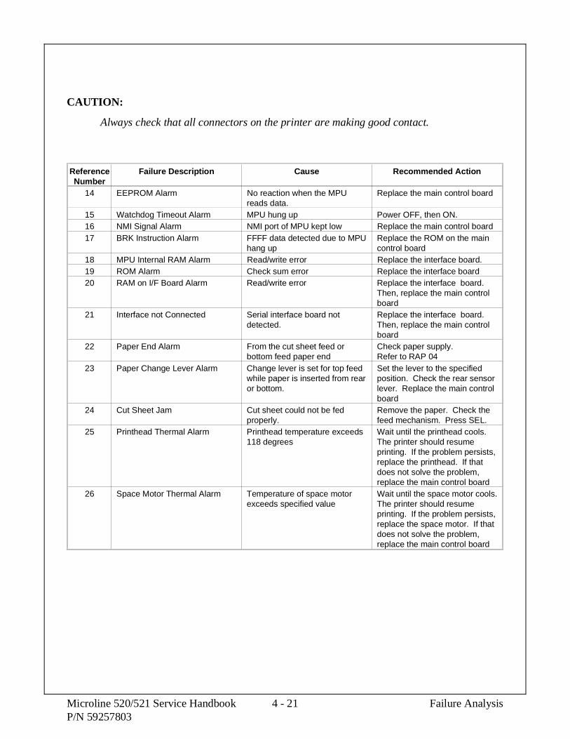
CAUTION:
Always check that all connectors on the printer are making good contact.
ReferenceNumber
Failure Description Cause Recommended Action
14 EEPROM Alarm No reaction when the MPUreads data.
Replace the main control board
15 Watchdog Timeout Alarm MPU hung up Power OFF, then ON.16 NMI Signal Alarm NMI port of MPU kept low Replace the main control board17 BRK Instruction Alarm FFFF data detected due to MPU
hang upReplace the ROM on the maincontrol board
18 MPU Internal RAM Alarm Read/write error Replace the interface board.19 ROM Alarm Check sum error Replace the interface board20 RAM on I/F Board Alarm Read/write error Replace the interface board.
Then, replace the main controlboard
21 Interface not Connected Serial interface board notdetected.
Replace the interface board.Then, replace the main controlboard
22 Paper End Alarm From the cut sheet feed orbottom feed paper end
Check paper supply.Refer to RAP 04
23 Paper Change Lever Alarm Change lever is set for top feedwhile paper is inserted from rearor bottom.
Set the lever to the specifiedposition. Check the rear sensorlever. Replace the main controlboard
24 Cut Sheet Jam Cut sheet could not be fedproperly.
Remove the paper. Check thefeed mechanism. Press SEL.
25 Printhead Thermal Alarm Printhead temperature exceeds118 degrees
Wait until the printhead cools.The printer should resumeprinting. If the problem persists,replace the printhead. If thatdoes not solve the problem,replace the main control board
26 Space Motor Thermal Alarm Temperature of space motorexceeds specified value
Wait until the space motor cools.The printer should resumeprinting. If the problem persists,replace the space motor. If thatdoes not solve the problem,replace the main control board
Microline 520/521 Service Handbook 4 - 21 Failure AnalysisP/N 59257803

4.7 REPAIR ANALYSIS PROCEDURES (RAPs)
4.7.01 Using the RAPs
When using the Repair Analysis Procedures, follow these steps.
1. Go to the RAP Index.
2. Find the RAP which is associated with the printer’s problem.
3. Go to the appropriate RAP.
4. All RAPs begin with a START statement, followed by questions or another type ofstatement.
Failure Analysis 4 - 22 Microline 520/521 Service HandbookP/N 59257803

4.7.02 RAP Index
RAP Number Description1 No Power Supplied to Printer2 No Spacing Operation3 Printhead Homing Error4 Paper Jam During Paper Loading5 Printhead Not Firing Pins6 Poor Print Quality7 Ribbon Feed Problem8 Line Feed Problem9 Operator Panel Malfunction
10 Parallel Interface Problem11 Serial Interface Problem
Microline 520/521 Service Handbook 4 - 23 Failure AnalysisP/N 59257803

RAP 01 No Power Supplied to Printer
START
The printer does not power On when the AC switch is turned ON.
Check the AC cable.
Is it correctly connected?
Yes Check the fuse on the power supply board and F1 of the main control board.Are they open?
No Go to A.
Yes Replace the fuse(s) with fuse(s) of the same rating.
Is the problem resolved?
Yes End of procedure.
No Go to A.
B
No Remove the cable from CN3 on the main control board.
Refer to Appendix A of this Service Handbook for voltage check points on CN3 of themain control board. Check the output voltages of the secondary of the transformer.
Replace the following in the order listed below. Check operation before replacing nextitem in list.
1. Operation Panel.
2. Power Transformer.
Has the problem been resolved?
Yes End of procedure.
No Contact Technical Support.
Failure Analysis 4 - 24 Microline 520/521 Service HandbookP/N 59257803

A
Remove the cable from CN7 of the main control board. Then, power ON the unit.
Do the operation panel LEDs light?
No Go to B.
Yes Power OFF the unit. Remove the printhead. Power ON the unit.
Has the problem been resolved?
Yes Replace the printhead.
Has the problem been resolved?
Yes End of procedure.
No Go to B.
No Replace the following in the order listed below. Check operation before replacingnext item in list.
1. Ribbon Feed Mechanism.
2. Carriage Cable.
3. Main Control Board
4. PROM 05CA
Has the problem been resolved?
Yes End of procedure.
No Contact Technical Support.
Microline 520/521 Service Handbook 4 - 25 Failure AnalysisP/N 59257803

RAP 02 No Spacing Operation
START
The alarm LED blinks.
Is the carriage assembly binding or jammed?
No Make sure the carriage cable is properly connected to the space motor assembly andCN7 on the main control board.
Go to A.
Yes 1. Remove the ribbon to verify that the ribbon is not jammed.
2. Remove the space motor assembly
3. Inspect the teeth on the space rack and the space motor gear.
4. Go to A.
A
Has the problem been resolved?
Yes End of procedure.
No Is the fuse F2 on the main control board open?
No Go to B.
Yes Replace the main control board.
Has the problem been resolved?
Yes End of procedure.
No Go to B.
Failure Analysis 4 - 26 Microline 520/521 Service HandbookP/N 59257803

B
Verify that +40 volts is present on CN7 main control board (Refer to Appendix A of the ServiceHandbook).
Has the problem been resolved?
Yes End of procedure.
No Replace the carriage cable.
Has the problem been resolved?
Yes End of procedure.
No Replace the ribbon feed mechanism
Has the problem been resolved?
Yes End of procedure.
No Replace the PROM (O5CA)
Has the problem been resolved?
Yes End of procedure.
No Contact Technical Support.
Microline 520/521 Service Handbook 4 - 27 Failure AnalysisP/N 59257803

RAP 03 Printhead Homing Error
START
Printhead does not return to the home position.
Make sure the carriage cable is properly connected to the space motor assembly and CN8 on themain control board.
Make sure the power connector cable is properly connected to CN3 on the main control board.
Does the space motor assembly move manually?
No Remove the space motor assembly and inspect the space motor and space rack for dirtand worn teeth.
Go to A
Yes Are there any breaks in the carriage cable?
Yes Replace the carriage cable assembly.
Go to A
No Verify that ribbon feed mechanism is properly fastened to the space motorassembly.
Go to A
Failure Analysis 4 - 28 Microline 520/521 Service HandbookP/N 59257803

A
Does the carriage move slightly to the left after turning the power on?
No Replace the space motor assembly.
Has the problem been resolved?
Yes End of procedure.
No Contact Technical Support.
Yes Replace the ribbon feed assembly.
Has the problem been resolved?
Yes End of procedure.
No Replace the main control board.
Has the problem been resolved?
Yes End of procedure.
No Replace the space motor assembly.
Has the problem been resolved?
Yes End of procedure.
No Contact Technical Support.
Microline 520/521 Service Handbook 4 - 29 Failure AnalysisP/N 59257803

RAP 04 Paper Jam During Paper Loading
START
Check paper path release lever for proper position. Make sure the paper path is clear.
Which of the following paper jams have occurred?
1. Paper bent at top left corner.
Check the support protector to see if it covers the left side of the paper properly.
Go to A.
2. Paper has torn ends.
Check the ribbon protector.
Check the pull up roller cover to see that it is closed properly.
Go to A.
3. Paper squeezed from either end.
Check around the pressure roller mechanism.
Check the front pressure springs to see that they are mounted properly. There arethree springs in the Microline 520 and five springs in the Microline 521.
Check the tension of all the front pressure rollers to see if they are the same. Topsprings: 250 g. Rear Springs: 90 g.
Make sure that the front release gear arm and the gear of the front release gear shaftare in the proper position.
Go to A.
A
Has the problem been resolved?
Yes End of procedure.
No Check that the head gap is set properly.
Has the problem been resolved?
Yes End of procedure.
No Contact Technical Support.
Failure Analysis 4 - 30 Microline 520/521 Service HandbookP/N 59257803

RAP 05 Printhead Pins Not Firing
START
Missing dots on output.
Verify that the printhead gap is set correctly.
Ensure the carriage cable is making firm contact with CN7 on the main control board and thespace motor assembly. Inspect both ends of the carriage cable for worn edges.
Has the problem been resolved?
Yes End of procedure.
No Replace the printhead.
Has the problem been resolved?
Yes End of procedure.
No Replace the main control board
Has the problem been resolved?
Yes End of procedure.
No Replace the carriage cable.
Has the problem been resolved?
Yes End of procedure.
No Replace the space motor assembly.
Has the problem been resolved?
Yes End of procedure.
No Contact Technical Support.
Microline 520/521 Service Handbook 4 - 31 Failure AnalysisP/N 59257803

RAP 06 Poor Print Quality
START
Is the print head gap properly set?
Yes Go to A
No Go to B
A Replace the printhead
Has the problem been resolved?
Yes End of procedure.
No Go to C.
C Replace the main control board.
Has the problem been resolved?
Yes End of procedure.
No Check that the carriage cable is making good contact with the main controlboard and the carriage assembly. Replace the cable if it is worn or bent.
Has the problem been resolved?
Yes End of procedure.
No Contact Technical Support.
B Adjust the print head gap (Refer to Section 3 of this Service Handbook).
Has the problem been resolved?
Yes End of procedure.
No Power ON the unit and view the head gap indicator.
Does the head gap indicator display a range of 9?
Yes Go to A
No Replace the ribbon feed mechanism.
Has the problem been resolved?
Yes End of procedure.
No Go to C
Failure Analysis 4 - 32 Microline 520/521 Service HandbookP/N 59257803

RAP 07 Ribbon Feed Problem
START
The ribbon feed does not function properly.
Verify that both ends of the carriage cable are connected correctly.
Make sure the ribbon shield is fastened properly.
Remove the ribbon cartridge.
Grasp the carriage. Manually move the carriage left and right.
Does the ribbon drive shaft rotate?
Yes Change the ribbon cartridge.
End of procedure.
No Remove the ribbon feed mechanism.
Manually move the carriage left and right.
Does the space motor shaft rotate freely?
Yes Replace the ribbon feed mechanism.
End of procedure.
No Replace the space motor assembly.
Has the problem been resolved?
Yes End of procedure.
No Replace the main control board.
Has the problem been resolved?
Yes End of procedure.
No Contact Technical Support.
Microline 520/521 Service Handbook 4 - 33 Failure AnalysisP/N 59257803

RAP 08 Line Feed Problem
START
No line feed operation.
Make sure that the line feed cable is properly connected to the line feed motor and CN5 of themain control board.
Power OFF the printer. Manually rotate the platen.
Does the platen rotate smoothly?
Yes Go to A
No Is the left platen gear broken?
Yes Replace the platen assembly.
End of procedure.
No Is the line feed idle gear broken?
Yes Replace the line feed motor assembly or the line feed idle gear.
End of procedure.
No Are the right platen gear, idle gear and/or change gear broken?
Yes Replace the respective assembly.
End of procedure.
No Set the change lever to the rear position.
Does the platen rotate smoothly?
Yes Replace the tractor feed assembly.
End of procedure.
No Check the gears on the tractor feed assembly and platen assembly forbroken or missing teeth. Replace the defective assembly.
Go to A
Failure Analysis 4 - 34 Microline 520/521 Service HandbookP/N 59257803

A
Replace the line feed motor assembly.
Has the problem been resolved?
Yes End of procedure.
No Replace the main control board.
Has the problem been resolved?
Yes End of procedure.
No Contact Technical Support.
Microline 520/521 Service Handbook 4 - 35 Failure AnalysisP/N 59257803

This page was intentionally left blank.
Failure Analysis 4 - 36 Microline 520/521 Service HandbookP/N 59257803

RAP 09 Operation Panel Malfunction
START
The operation panel does not function properly.
Do the operation panel LEDs light when power is applied?
Yes Make sure the cable from CN1 of the operation panel is properly connected to CN7on the main control board.
Go to A
No Check the F1 fuse on the main control board and the fuse on the power supply board. Are they open?
Yes Replace the open fuse with one that has the proper rating.
Go to A
No Replace the power supply unit.
Go to A
A
Has the problem been resolved?
Yes End of procedure.
No Replace the operation panel board.
Has the problem been resolved?
Yes End of procedure.
No Replace the main control board.
Has the problem been resolved?
Yes End of procedure.
No Contact Technical Support.
Microline 520/521 Service Handbook 4 - 37 Failure AnalysisP/N 59257803

RAP 10 Parallel Interface Problem
START
No parallel port communication.
Is the SEL LED blinking?
Yes The printer is in the Print Suppress mode.
Disable the menu item Print Suppress if the function is not required.
End of procedure.
No Does the SEL LED light ?
Yes Go to A
No Press SEL key.
Has the problem been resolved?
No Disconnect the cable.
Does the SEL LED light ?
Yes Change the menu item I-prime to invalid.
No Go to A
Yes Is data being received properly?
Yes End of procedure.
No Check that the cable is properly connected to the Host PC and the correctLPT port is selected.
Does the SEL LED light?
No Go to A
Yes Change the menu item I-prime to invalid.
End of procedure.
Failure Analysis 4 - 38 Microline 520/521 Service HandbookP/N 59257803

A
Replace the interface cable.
Has the problem been resolved?
Yes End of procedure.
No Replace the main control board.
Has the problem been resolved?
Yes End of procedure.
No Contact Technical Support.
Microline 520/521 Service Handbook 4 - 39 Failure AnalysisP/N 59257803

RAP 11 Serial Interface Problem
START.
Are you using a cable with the proper number of pins?
No Change the interface cable.
Has the problem been resolved?
Yes End of procedure
No Go to A
Yes Is the ALARM LED blinking?
Yes Refer to Section 4.6 of the Service Handbook.
Has the problem been resolved?
Yes End of procedure
No Go to A
No Go to A
A
Check the serial interface parameters for the RS232C (in the Printer Menu): baud rate,word length, parity, protocol, busy signal and parity.
Has the problem been resolved?
Yes End of procedure
No Go to B
Failure Analysis 4 - 40 Microline 520/521 Service HandbookP/N 59257803

B
Check the voltages on the main control board.
Is 10 VAC being supplied to the main control board?
Yes Replace the RS232C board.
Has the problem been resolved?
Yes End of procedure.
No Replace the main control board.
Has the problem been resolved?
Yes End of procedure.
No Contact Technical Support.
No Replace the power supply unit.
Has the problem been resolved?
Yes End of procedure.
No Replace the RS232C board.
Are + 8 vdc / - 8 vdc present on the main control board? (Refer to Appendix Aof this Service Handbook).
Yes Replace the RS232C board.
Has the problem been resolved?
Yes End of procedure.
No Contact Technical Support.
No Replace the main control board.
Has the problem been resolved?
Yes End of procedure.
No Contact Technical Support.
Microline 520/521 Service Handbook 4 - 41 Failure AnalysisP/N 59257803

This page was intentionally left blank
Failure Analysis 4 - 42 Microline 520/521 Service HandbookP/N 59257803

4.8 PRINTER TESTS
4.8.01 General Information
This section covers the tests listed below.
• Rolling ASCII Test
• Font Test
• Serial Interface Loopback Test
• Hexadecimal Dump Mode
The Rolling ASCII and Font Tests check print operations.
The Serial Interface Loopback Test checks the operation of the serial interface board.
The Hexadecimal Dump Mode checks the data transfer between the computer and printer.
Microline 520/521 Service Handbook 4 - 43 Failure AnalysisP/N 59257803

4.8.02 Rolling ASCII Test
General Information
The rolling ASCII test is a continuous printout of all 96 ASCII characters.
Use this test to check the following items.
1. Print Quality
Across the entire length of a line
Down the entire page
2. Line Spacing
3. Left Margin Alignment
At the top of the test is the printer type (1), emulation (2), country (3), and firmware revisionlevel (4). This information is often required while performing service or when contactingOkidata. Have this test available during your service call.
CAUTION
Before running this test, make sure that continuous feed paper is loaded.
If you are running this test on a Microline 521, use wide paper or have the page widthset for 8.5" x 11" in the printer menu.
Running the test without paper loaded or having the wrong width paper loaded willallow the printhead to print on the platen. This will dirty the platen, cause excessivewear on the ribbon, and may damage the platen, ribbon, and printhead.
Procedure
Follow these steps to print the Rolling ASCII Test.
1. Load the correct size continuous feed paper.
2. Power off the printer.
3. Press and hold the QUIET switch while powering on the printer. You must hold theQUIET switch until the test starts to print.
4. The test will continue to print until you press the SEL switch or run out of paper.
Failure Analysis 4 - 44 Microline 520/521 Service HandbookP/N 59257803

Sample
1 2 43
4-8-02.tif
Microline 520/521 Service Handbook 4 - 45 Failure AnalysisP/N 59257803

4.8.03 Font Test
General Information
The font test is a one page sample printout of each available typeface.
HSD 10 cpi
HSD 12 cpi
HSD 17.1 cpi
Utility 10 cpi
Utility 12 cpi
Utility 17.1 cpi
NLQ 10 cpi
NLQ 12 cpi
NLQ 10 cpi Double Height / Double Width
At the top of the test is the printer type (1), emulation (2), country (3), and firmware revisionlevel (4). This information is often required while performing service or when contactingOkidata. Have this test available during your service call.
CAUTION
Running the test without paper loaded will allow the printhead to print on the platen.This will dirty the platen, cause excessive wear of the ribbon, and may damage theplaten, ribbon, and printhead.
Procedure
Follow these steps to print the font test.
1. Load the paper.
2. Power off the printer.
3. Press and hold the LF switch while powering on the printer. You must hold the LFswitch until the test starts to print.
4. The one page test will print, then stop.
Failure Analysis 4 - 46 Microline 520/521 Service HandbookP/N 59257803

Sample
1 24
3
4-8-03.tif
Microline 520/521 Service Handbook 4 - 47 Failure AnalysisP/N 59257803

4.8.04 Serial Interface Loopback Test
NOTE:
In order to run this test, the serial interface board must be installed with a serialloopback test connector attached to it.
To perform the serial interface loopback test, follow these steps.
1. Place the printer in the Serial Diagnostic mode.
Set the Diagnostic Test menu item to YES.
2. Power off the printer.
3. Attach the loopback connector to the serial port.
4. Install continuous feed paper.
5. Power on the printer.
6. The message LOOP TEST prints.
7. The size of the Message Buffer prints.
8. One of the following three messages prints next.
If the message OK prints, the message buffer has been tested and noproblems were found.
If the message BAD prints, there is a problem with the message buffer.
If the message IF BAD prints, the signal logic was tested and a problem wasfound.
9. Hexadecimal characters 20 through 7F are transmitted through the transmit data line.
10. The receive data line receives the characters.
11. The message buffer stores the characters.
12. The data prints.
13. The test runs until the printer is powered off or the SELECT switch is pressed.
Failure Analysis 4 - 48 Microline 520/521 Service HandbookP/N 59257803

Loopback Connector Configuration
1. Jumper the following pins together.
Pin 2 to Pin 3
Pin 4 to Pin 5
Pin 8 to Pin 11
Pin 6 to Pin 20
RS232-C Serial Loopback Test Connector
(DB25P Plug) 4-8-04.tif
Microline 520/521 Service Handbook 4 - 49 Failure AnalysisP/N 59257803

Serial Cable Information
The information in this section will help you make a serial cable to connect between the printerand computer.
Refer to the computer documentation to determine the cable requirements on the computers end.
The printer has the following cable requirements.
• Shielded, RS-232C cable
• UL and CSA approved
• No more than 50 feet long
• Cannon DB-25P plug (or equivalent) with 25 pins
• Cannon DB-C2-J9 (or equivalent) connector shell
Serial Interface Signal Requirements
Pin Signal Symbol Direction Description1 Protective Ground PG Ground Connected to the printer frame
2 Transmit Data TD From Printer Serial data transmitted to the system
3 Receive Data RD To Printer Serial data received by the printer
4 Request to Send RTS From Printer Always set to low (mark)
5 Not Used
6 Data Set Ready DSR To Printer Indicates that data can be sent
7 Signal Ground SG Ground Ground
8to10
Not Used
11 Supervisory Send Data SSD From Printer Indicates that the printer is not ready toreceive data
12to
19
Not Used
20 Data Terminal Ready DTR From Printer Indicates that the printer is not ready toreceive data
21to
25
Not Used
Failure Analysis 4 - 50 Microline 520/521 Service HandbookP/N 59257803

Commonly Used Serial Cable Configurations
IBM 25-Pin Cable Configuration
Computer PrinterPG 1 1 PGTD 2 3 RDRD 3 2 TD
CTS 5 11 SSDDSR 6 20 DTR
6 DSRSG 7 7 SG
4 RTS
5 CTS
IBM 9-Pin Cable Configuration
Computer PrinterRD 2 2 TDTD 3 3 RDSG 5 7 SG
DSR 6 20 DTR
6 DSRCTS 8 11 SSD
4 RTS
5 CTS
Microline 520/521 Service Handbook 4 - 51 Failure AnalysisP/N 59257803

4.8.05 Hexadecimal Dump Mode
General Information
The hexadecimal dump mode allows you to view the data sent from a computer to the printer.When the printer is in hex dump mode, all data received (both printable characters and controlcodes) will be printed in both hexadecimal and ASCII format.
NOTE:
In the ASCII format, all non-printable characters will be represented by a period.
Example
Below is a line of BASIC code.
LPRINT CHR$(27) ;"0";CHR$(30);"This is an example of hexadecimal dump."
Below is the same line as it would appear in Hexadecimal Dump Mode.
1B 30 1E 54 68 69 73 20 69 73 20 61 6E 20 65 78 .0. This is an ex
61 6D 70 6C 65 20 66 20 61 20 68 65 78 61 64 ample of a hexad
65 63 69 6D 61 6C 20 64 75 6D 70 2E 0D 0A ecimal dump
Procedure
Follow these steps to engage the Hexadecimal Dump Mode.
1. Make sure the printer is connected to a computer.
2. Verify that paper is loaded.
3. Verify that the ribbon and printhead are correctly installed.
4. Power OFF the printer.
5. Press and hold the SEL and FF/LOAD switches while powering on the printer.
6. Hold the switches until the printer prints the line:
Hex Data Dump
7. The printer is ready to receive data in the Hexadecimal Dump Mode.
8. Send data to the printer from the computer.
9. To exit Hexadecimal Dump Mode, power OFF the printer.
Failure Analysis 4 - 52 Microline 520/521 Service HandbookP/N 59257803

Sample
4-8-05.tif
Microline 520/521 Service Handbook 4 - 53 Failure AnalysisP/N 59257803

4.9 RESISTANCE CHECKS
4.9.01 General Description
The charts on the following pages provide information needed to determine if the printhead andmotors used in the printer are defective.
NOTE:
The printhead coil resistance values ARE NOT LISTED.
The individual printwire control lines CANNOT be accessed on this printhead.
Failure Analysis 4 - 54 Microline 520/521 Service HandbookP/N 59257803
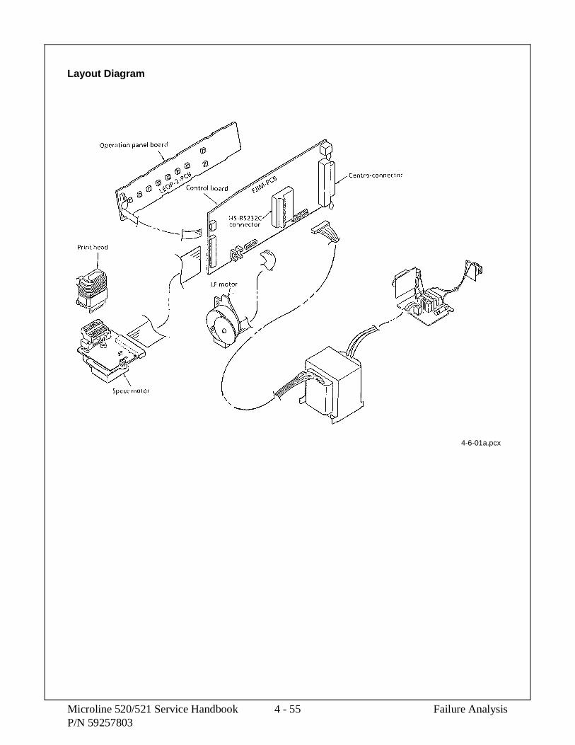
Layout Diagram
4-6-01a.pcx
Microline 520/521 Service Handbook 4 - 55 Failure AnalysisP/N 59257803

4.9.02 Printhead
Interconnect Diagram: Control Board to Printhead
NOTE:
The printhead coil resistance values ARE NOT LISTED.
The individual printwire control lines CANNOT be accessed on this printhead.
4-9-02.pcx
Failure Analysis 4 - 56 Microline 520/521 Service HandbookP/N 59257803

4.9.03 Line Feed Motor Resistance
The resistance of each coil should be approximately 13 ohms.
4.9.04 Space Motor Resistance
The resistance of each coil should be approximately 5 ohms.
4-9-03.pcx
4-9-04.pcx
Microline 520/521 Service Handbook 4 - 57 Failure AnalysisP/N 59257803

This page was intentionally left blank.
Failure Analysis 4 - 58 Microline 520/521 Service HandbookP/N 59257803

APPENDIX A
BOARD DIAGRAMS


A.1 OVERVIEW
A.1.01 General Information
This section describes the characteristics of the printed circuit boards used in the unit.
The following areas are covered.
Function
Firmware
Fuses
Jumpers
Sensors
Switches
Test Points
Where an item is not applicable, the word NONE will be listed.
Microline 520/521 Service Handbook A - 1 Board DiagramsP/N 59257803
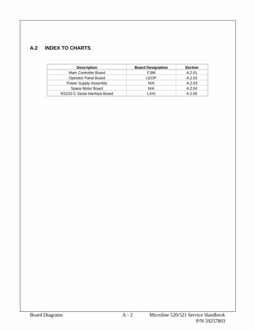
A.2 INDEX TO CHARTS
Description Board Designation SectionMain Controller Board FJIM A.2.01Operator Panel Board LEOP A.2.02
Power Supply Assembly N/A A.2.03Space Motor Board N/A A.2.04
RS232-C Serial Interface Board LXHI A.2.05
Board Diagrams A - 2 Microline 520/521 Service HandbookP/N 59257803

A-2-00.pcx
Microline 520/521 Service Handbook A - 3 Board DiagramsP/N 59257803

A.2.01 Main Controller Board (FJIM)
Function
The main controller board contains a microprocessor, EPROM, EEPROM, drive circuitry, 128Kbyte DRAM, sensors and interface connector. The AC voltages from the power supply arerectified and regulated on the main controller board.
Firmware
05CB: CMOS Dynamic RAM (1 MBit)
05CA: EPROM (Program)
Fuses
F1: 125 Volt 2 amp. (AC line fuse)
F2: soldered - 2 amp. (protects the +40vdc motor drive circuit)
Jumpers
NONE
Sensors
SNS1: Rear / Top Feed Paper Out Sensor
SNS2: Bottom Feed Paper Out Sensor
Switches
BASW: Paper Path Select Switch
Test Points
Frame GroundCN1 pins 37,38
Logic Ground CN1 pin 33
+5 vdc : CN7 - Pin 6 (logic circuitry voltage)
+40 vdc: CN7 - Pins 29 and 31(Printhead, Space Motor / Line Feed Motor Drive Voltage)
Board Diagrams A - 4 Microline 520/521 Service HandbookP/N 59257803

05CB(DRAM))
05CA
BASW
SNS1SNS2
F2
CN31 8
F1
CN7
A-2-01.pcx
Microline 520/521 Service Handbook A - 5 Board DiagramsP/N 59257803

A.2.02 Operator Panel Board (LEOP)
Function
The operator panel control LSI send commands to the microprocessor’s serial I/O port wheneverthe operator panel’s switches are pressed. The operator panel LED display provides informationon fault alarms and printer status.
Firmware
NONE
Fuses
NONE
Jumpers
NONE
Sensors
NONE
Switches
SEL (Select)
SHIFT
LF (Line Feed)
FF (Form Feed)
TEAR
PARK
QUIET
PQ (Print Quality)
CP (Character Pitch)
Test Points
NONE
Board Diagrams A - 6 Microline 520/521 Service HandbookP/N 59257803

SEL
CP
PQ
QUIETPARKTEARFFLFSHIFT
LEOP PCB
A-2-02.pcx
Microline 520/521 Service Handbook A - 7 Board DiagramsP/N 59257803

A.2.03 Power Supply Assembly
Function
The power supply board is comprised of a noise filter board and transformer. The power supplyboard provides AC voltages to the main controller board via CN-3.
Firmware
NONE
Fuses
F1: 125/250V 2.5 amp. AC line fuse
Jumpers
NONE
Sensors
NONE
Switches
SW: Power Switch
Test Points
Transformer secondary voltages
CN 3 pin 1: 17.5 VAC
CN 3 pin 2: 0 VAC
CN 3 pin 3: 6.6 VAC
CN 3 pin 4: 0 VAC
CN 3 pin 5: 0 VAC
CN 3 pin 6: 6.6 VAC
CN 3 pin 7: 0 VAC
CN 3 pin 8 : 18.5 VAC
Board Diagrams A - 8 Microline 520/521 Service HandbookP/N 59257803

Secondary
Primary
(6 wires)
Transformer
ON / OFFSwitch
To Main Controller
Frame Ground
F1
Noise FilterBoard
A-2-03.pcx
Microline 520/521 Service Handbook A - 9 Board DiagramsP/N 59257803

A.2.04 Space Motor Board
Function
The space motor board contains an encoder disk and photosensor. The encoder disk and thephotosensor generate phase signals. These signals governs the speed and direction of the spacemotor via the LSI and microprocessor.
Firmware
NONE
Fuses
NONE
Jumpers
NONE
Sensors
Photosensor: used to monitor space motor movement.
Switches
NONE
Test Points
NONE
Board Diagrams A - 10 Microline 520/521 Service HandbookP/N 59257803

EncoderDisk
Connector(Auto-Gap Mechanism)
Printhead GapAdjusting Screw
Space motor Assembly
Photosensor
A-2-04.pcx
Microline 520/521 Service Handbook A - 11 Board DiagramsP/N 59257803
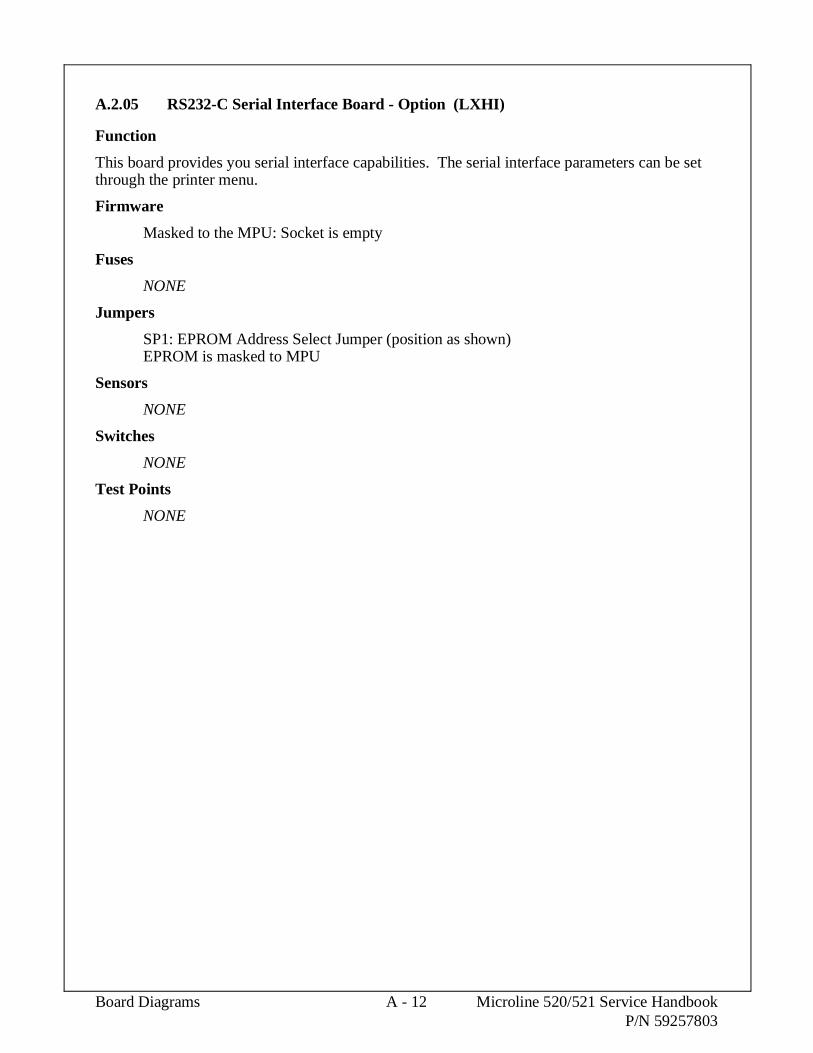
A.2.05 RS232-C Serial Interface Board - Option (LXHI)
Function
This board provides you serial interface capabilities. The serial interface parameters can be setthrough the printer menu.
Firmware
Masked to the MPU: Socket is empty
Fuses
NONE
Jumpers
SP1: EPROM Address Select Jumper (position as shown)EPROM is masked to MPU
Sensors
NONE
Switches
NONE
Test Points
NONE
Board Diagrams A - 12 Microline 520/521 Service HandbookP/N 59257803

MPU
SP1
Default Setting
A-2-05.tif
Microline 520/521 Service Handbook A - 13 Board DiagramsP/N 59257803

This page was intentionally left blank.
Board Diagrams A - 14 Microline 520/521 Service HandbookP/N 59257803

APPENDIX B
ILLUSTRATED PARTS LISTING


B.1 OVERVIEW
B.1.01 General Information
This appendix will assist you in identifying the assemblies and parts of the product.
Use Section Four (Failure Analysis) to determine the defective part(s).
Locate the part and its part number in this section.
Appendix B is cross-referenced to Section Three (Maintenance).
Microline 520/521 Service Handbook B - 1 Illustrated Parts ListingP/N 59257803

Format
The format for this appendix is a series of tables with diagrams. The tables contain the itemreference number, the Okidata and Oki-Japan (Oki-J) part numbers, the part description, acomments section, and the disassembly procedure.
Item Okidata P/NOki-J P/N
Description CommentsRefer to B.1.02
DisassemblyProcedure
Items with the comments RSPL (Recommended Spare Parts List), Consumable, Document, orOption are available from Okidata. Items without these comments are usually not stocked.
Some items are only available as assemblies. Every effort has been made to clearly indicatewhich items are in assemblies and which are not.
N/A will appear where a part number is not available.
Illustrated Parts Listing B - 2 Microline 520/521 Service HandbookP/N 59257803

Current Part Numbers
Okidata has made every effort to include current part numbers in this Service Handbook at thetime of publishing.
However, technical information frequently changes. These changes often include new ormodified parts, with new or modified part numbers.
Please refer to the following resources for current part numbers and pricing.
• Okidata’s Electronic Bulletin Board (Okilink II) contains current part numbers,prices, and recommended stocking levels for each item listed as a recommendedspare part. For instructions on accessing Okilink II, refer to the Service CenterReference Guide.
• Okidata’s Faxable Facts is an automated fax document retrieval system. Partnumbers and pricing are available through Faxable Facts. For instructions onaccessing Faxable Facts, refer to the Service Center Reference Guide.
• Okidata’s Technical Information Group is a telephone support line reserved forAuthorized Dealers. Part numbers and pricing are available through TechnicalInformation. For instructions on accessing Technical Information, refer to theService Center Reference Guide.
REMEMBER
Current part numbers, recommended stocking levels, and pricing information areavailable through Okilink II, Faxable Facts, and Technical Information. Refer to theService Center Reference Guide for information on accessing these resources.
Microline 520/521 Service Handbook B - 3 Illustrated Parts ListingP/N 59257803

B.1.02 Definition of Terms
Assemblies
Assemblies are parts grouped under a single description and/or part number. Generally,individual items in an assembly are not available from Okidata.
Assemblies are surrounded by broken line boxes in the diagrams.
Assemblies will say "Includes xx xx" under the Comments section of the tables.
Parts in assemblies will say "Part of xx" under the Comments section of the tables.
Blank
Okidata does not recommend stocking this item. This item should be purchased on anAs Required Basis only.
The availability of this item is NOT guaranteed by Okidata.
Consumable
A consumable is a supply item which has a specified life and must be periodicallyreplaced. It is purchased and installed by the end user. Okidata machines are designedto work exclusively with Okidata consumables. By using genuine Okidata consumableproducts, the investment made in the equipment is protected.
Document
A document is a printed item which supports the service and marketing of a product.Various documents are available from Okidata.
Drivers
Printer drivers are updated frequently. Please refer to Okilink II for the latest printerdriver information.
Firmware
Firmware is revised frequently. Please refer to Okilink II for the latest firmwareinformation.
Option
An option is a part/assembly which is added to a product. The option expands theproduct’s functionality. An option may or may not be installed by the end user.Instructions for installation accompany each option.
Option RSPL
Okidata recommends that this part/assembly be on hand for servicing installed options.
RSPL
Okidata recommends that this part/assembly be on hand for servicing.
Illustrated Parts Listing B - 4 Microline 520/521 Service HandbookP/N 59257803

Technical Service Bulletins
Technical Service Bulletins (TSBs) are also referred to as Okidata’s monthly mail.
The TSBs contain the latest information on firmware revisions, procedure changes, andtechnical information updates.
Okidata distributes the TSBs through Okilink II. The TSBs are issued monthly.
520
This part is specific to the Microline 520 printer.
521
This part is specific to the Microline 521 printer.
Both
This part is used by both the Microline 520 and Microline 521 printers.
Microline 520/521 Service Handbook B - 5 Illustrated Parts ListingP/N 59257803

B.1.03 Parts Ordering Information
Service Center Reference Guide
When a technician has successfully completed a Service Training Course for a product and theDealer has become Service Authorized, an information package is provided to the Dealer. TheOkidata Service Center Reference Guide outlines the following items.
• Responsibilities of Okidata Service Centers
• Spare parts and consumables information
• Procedures for warranty repairs
• Product Training, Certification, and Authorization
• Product Support information
• Okidata Depot information and services
• Third Party Service information
• Information about Okidata’s Customer Information Center
• Okidata Service and Support telephone numbers.
The Service Center Reference Guide contains the procedures to follow for ordering parts.Please read, understand, and follow these procedures. Service Authorization for a specificproduct must be obtained before a Dealer can submit warranty claims.
Direct questions regarding the Service Center Reference Guide to Okidata Dealer Service.Refer to the Service Center Reference Guide for information on contacting Okidata.
Illustrated Parts Listing B - 6 Microline 520/521 Service HandbookP/N 59257803

Placing a Parts Order
All authorized Okidata resellers may order spare parts and consumables for Okidata products.Orders are placed through Okidata’s Logistics Department.
Please refer to your Service Center Reference Guide for details on ordering parts.
You should have the following information available before you place your order.
• Okidata Dealer Authorization Number
• Okidata Customer Number
• Your Purchase Order Number
• Okidata Part Number(s)
Use this Appendix, Okilink II, Faxable Facts, or contact Okidata Technical Support to find thecorrect part number. Refer to the Service Center Reference Guide for information on contactingOkidata.
Microline 520/521 Service Handbook B - 7 Illustrated Parts ListingP/N 59257803

B.2 CHARTS
Below is an index to the illustrated parts breakdown charts.
Section DescriptionB.2.01 PrinterB.2.02 Upper Cover AssemblyB.2.03 Printer General AssemblyB.2.04 Printer Unit (1 of 3)B.2.05 Printer Unit (2 of 3)B.2.06 Printer Unit (3 of 3)B.2.07 Carriage AssemblyB.2.08 OptionsB.2.09 Option PartsB.2.10 ConsumablesB.2.11 Packing MaterialsB.2.12 DocumentationB.2.13 Service Training Kit Revision List
Illustrated Parts Listing B - 8 Microline 520/521 Service HandbookP/N 59257803

Sheet Guide Assembly
Access Cover Assembly
Upper Cover
Main Frame
Operation Board Assembly
Control Board
Pull-up Roller Assembly
Power Supply Assembly
AC Power Cable
B-2-00.pcx
Microline 520/521 Service Handbook B - 9 Illustrated Parts ListingP/N 59257803

B.2.01 Printer
Part numbers are subject to change. Refer to Okilink II for current part numbers and pricing information.
Item Okidata P/NOki-J P/N
Description CommentsRefer to B.1.02
DisassemblyProcedure
1 62409001N/A
Printer: ML520 Parallel(Epson/IBM/ML Comp.) 120 V
N/A
2 62409002N/A
Printer: ML520 Parallel(Epson/IBM/ML Comp.) 220 V
N/A
3 62410001N/A
Printer: ML521 Parallel(Epson/IBM/ML Comp.) 120 V
N/A
4 62410002N/A
Printer: ML521 Parallel(Epson/IBM/ML Comp.) 220 V
N/A
Illustrated Parts Listing B - 10 Microline 520/521 Service HandbookP/N 59257803

B-2-30.pcx
Microline 520/521 Service Handbook B - 11 Illustrated Parts ListingP/N 59257803

B.2.02 Upper Cover Assembly
Part numbers are subject to change. Refer to Okilink II for current part numbers and pricing information.
Item Okidata P/NOki-J P/N
Description CommentsRefer to B.1.02
DisassemblyProcedure
1 530669021PP4094-6501P2
Cover: Upper (Narrow) RSPL520
3.2.06
1 530670021PP4094-7201P2
Cover: Upper (Wide) RSPL521
3.2.06
2 51009401N/A
Guide: Sheet (Narrow) RSPL520
3.2.06
2 51009501N/A
Guide: Sheet (Wide) RSPL521
3.2.06
3 530671012PA4094-7381G1
Cover: Access (Narrow) RSPL520
3.2.06
3 530672012PA4094-7382G1
Cover: Access (Wide) RSPL521
3.2.06
Illustrated Parts Listing B - 12 Microline 520/521 Service HandbookP/N 59257803

1
3
2
B-2-01.pcx
Microline 520/521 Service Handbook B - 13 Illustrated Parts ListingP/N 59257803

B.2.03 Printer General Assembly
Part numbers are subject to change. Refer to Okilink II for current part numbers and pricing information.
Item Okidata P/NOki-J P/N
Description CommentsRefer to B.1.02
DisassemblyProcedure
1 535626012PP4094-6507P3
Knob: Platen (ML500 Series) RSPLBoth
3.2.06
2 530673012PP4094-6506P1
Cover: (B) for Card Slot RSPLBoth
3.2.06
3 550724014YA4042-1515G301
PCB: FJIM (w/o ROM) RSPLBoth
3.2.07
4 56301702540A2036M1202
Fuse: 2A 125V (GG52) RSPLBoth
N/A
5 559375024YA4042-1516G2
PCB: LEOP (Operator. Panel) RSPLBoth
3.2.09
6 535627033PP4025-3670G3
Panel: Operator RSPLBoth
3.2.09
7 564124014YB4049-7030P1
Transformer: 120 V ML520 RSPL520
3.2.08
7 564124024YB4049-7030P2
Transformer: 120 V ML521 RSPL521
3.2.08
8 550732014YB4021-1143P1
PCB: Filter 120 V RSPLBoth
3.2.08
9 566097013YS4011-1315P1
Cord: AC 120V RSPLBoth
3.2.01
10 500995014YA4023-2801G1
Printhead Assembly RSPLBoth
3.2.02
11 507075014PP4025-3621P1
Clamp: Cord RSPLBoth
3.2.08
12 56306201540A2062T2102
Fuse: 1A 250V (Filter Brd 220V) Option RSPLBoth
3.2.08
13 56306101540A2067T1252
Fuse: 2.5A 125V (Filter Board) RSPLBoth
3.2.08
Illustrated Parts Listing B - 14 Microline 520/521 Service HandbookP/N 59257803

1
2
3
5 6
7 8
9
10
11
4
12
13
B-2-02.pcx
Microline 520/521 Service Handbook B - 15 Illustrated Parts ListingP/N 59257803

B.2.04 Printer Unit
Part numbers are subject to change. Refer to Okilink II for current part numbers and pricing information.
Item Okidata P/NOki-J P/N
Description CommentsRefer to B.1.02
DisassemblyProcedure
1 535631013PA4025-3720G1
Frame: Main (Narrow) RSPL520
3.2.30
1 535632013PA4025-3721G1
Frame: Main (Wide) RSPL521
3.2.30
2 508046013PP4025-3315P1
Lever: Bottom Paper End RSPLBoth
3.2.27
3 508047013PP4025-3322P1
Lever: Bottom Sensor RSPLBoth
3.2.27
4 508048013PP4025-3321P1
Lever: Rear Sensor RSPLBoth
3.2.18
5 508049024PP4025-3323P2
Lever: Sensor (CutSheet/Continuous)
RSPLBoth
3.2.18
6 566272013PB4025-3356P1
Cord: Connection Line Feed RSPLBoth
3.2.21
7 565103023PB4025-3357P2
Motor: Line Feed Assembly RSPLBoth
3.2.21
8 512286013PB4055-2893P1
Gear: Line Feed Idle RSPLBoth
3.2.21
9 510103013PA4025-3387G1
Plate: Left Ground RSPLBoth
3.2.16
10 509230013PP4025-3320P1
Spring: Leaf (Narrow) RSPL520
3.2.26
10 509231013PP4025-3507P1
Spring: Leaf (Wide) RSPL521
3.2.26
11 530677013PP4025-3380P1
Cam: Adjust RSPLBoth
3.2.15
12 535633013PP4025-3376P1
Rack: Space (Narrow) RSPL520
3.2.13
12 535634013PP4025-3522P1
Rack: Space (Wide) RSPL521
3.2.13
13 509235014PB4025-3377P1
Spring: Tension (Space Rack) RSPLBoth
3.2.13
14 510097014PP4025-3378P1
Guide: Rail Ground Clip RSPLBoth
3.2.15
15 510098013PP4025-3379P1
Guide: Rail (Narrow) RSPL520
3.2.15
15 510099013PP4025-3523P1
Guide: Rail (Wide) RSPL521
3.2.15
16 535635014PP4025-3381P1
Shaft: Carriage (Narrow) RSPL520
3.2.25
16 535635024PP4025-3381P2
Shaft: Carriage (Wide) RSPL521
3.2.25
17 530676014PA4025-3382G1
Protector: Support (Assembly) RSPLBoth
3.2.25
18 509236014PB4025-3385P1
Spring: Support Protect Reset RSPLBoth
3.2.25
Illustrated Parts Listing B - 16 Microline 520/521 Service HandbookP/N 59257803

6
7
3
2
4
5
9 1
10
18
17
14
12
15
16
1311
8
B-2-03.pcx
Microline 520/521 Service Handbook B - 17 Illustrated Parts ListingP/N 59257803

B.2.05 Printer Unit
Part numbers are subject to change. Refer to Okilink II for current part numbers and pricing information.
Item Okidata P/NOki-J P/N
Description CommentsRefer to B.1.02
DisassemblyProcedure
1 535631013PA4025-3720G1
Frame: Main (Narrow) RSPL520
3.2.30
1 535632013PA4025-3721G1
Frame: Main (Wide) RSPL521
3.2.30
2 512280014PP4025-3340P1
Gear: Change RSPLBoth
3.2.29
3 512281013PP4025-3341P1
Gear: Tractor RSPLBoth
3.2.29
4 508053013PP4025-3352P1
Cam: Release RSPLBoth
3.2.24
5 512282014PP4025-3353P1
Gear: Idle RSPLBoth
3.2.23
6 508051012PP4025-3354P1
Lever: Change RSPLBoth
3.2.23
7 509232013PP4025-3355P1
Spring: Reset RSPLBoth
3.2.22
8 510102013PP4025-3386P1
Plate: Right Ground RSPLBoth
3.2.17
9 500983013PA4025-3370G1
Platen Assembly (Narrow) RSPL520
3.2.19
9 50098302N/A
Platen Assembly (Wide) RSPL521
3.2.19
10 533415013PA4025-3440G2
Roller: Pull Up Assembly (N) RSPL520
3.2.05
10 533416013PA4025-3530G2
Roller: Pull Up Assembly (W) RSPL521
3.2.05
Illustrated Parts Listing B - 18 Microline 520/521 Service HandbookP/N 59257803

910
4
2
8
3
756
1
B-2-04.pcx
Microline 520/521 Service Handbook B - 19 Illustrated Parts ListingP/N 59257803

B.2.06 Printer Unit
Part numbers are subject to change. Refer to Okilink II for current part numbers and pricing information.
Item Okidata P/NOki-J P/N
Description CommentsRefer to B.1.02
DisassemblyProcedure
1 535631013PA4025-3720G1
Frame: Main (Narrow) RSPL520
3.2.30
1 535632013PA4025-3721G1
Frame: Main (Wide) RSPL521
3.2.30
2 509229014PP4025-3316P1
Spring: Front Pressure (Narrow) RSPL520
3.2.28
3 509228014PP4025-3324P1
Spring: Front Pressure (Wide) RSPL521
3.2.28
4 533411014PP4025-3317P1
Holder: Front Roller RSPLBoth
3.2.28
5 533412024PP4025-3327G1
Roller: Front Pressure RSPLBoth
3.2.28
6 512278013PP4025-3318P1
Shaft: Front Release Gear (Narrow) RSPL520
3.2.27
6 512279013PP4025-3505P1
Shaft: Front Release Gear (Wide) RSPL521
3.2.27
7 50097301N/A
Pan: Paper (Narrow) RSPL520
3.2.27
7 500974011PP4025-3506P2
Pan: Paper (Wide) RSPL521
3.2.27
8 509233013PP4025-3346G1
Spring: Pressure (Narrow) RSPL520
3.2.24
8 509234013PP4025-3511G1
Spring: Pressure (Wide) RSPL521
3.2.24
9 508052014PP4025-3351P1
Lever: Switch (Cut Sheet/Continuous) RSPLBoth
3.2.24
10 512283014PP4025-3350P1
Arm: Front Release Gear RSPLBoth
3.2.24
11 509247014PP4025-3386P1
Spring: Lock RSPLBoth
3.2.20
12 500977013PA4025-3360G2
Paper Chute Assembly (Narrow) RSPL520
3.2.20
12 500978013PA4025-3515G2
Paper Chute Assembly (Wide) RSPL521
3.2.20
13 533413013PB4025-3364P1
Roller: Pressure Rear (Narrow) RSPL520
3.2.20
13 533414013PB4025-3517P1
Roller: Pressure Rear (Wide) RSPL521
3.2.20
14 500975013PA4025-3330G1
Tractor: Assembly (Narrow) RSPL520
3.2.29
14 500975023PA4025-3330G2
Tractor: Assembly (Wide) RSPL521
3.2.29
Illustrated Parts Listing B - 20 Microline 520/521 Service HandbookP/N 59257803

14
9
8
13
612
107
3
45
24
1
11
B-2-05.pcx
Microline 520/521 Service Handbook B - 21 Illustrated Parts ListingP/N 59257803

B.2.07 Carriage Assembly
Part numbers are subject to change. Refer to Okilink II for current part numbers and pricing information.
Item Okidata P/NOki-J P/N
Description CommentsRefer to B.1.02
DisassemblyProcedure
1 507074013PP4025-3431P1
Clamp: Head RSPLBoth
3.2.02
2 535628013PP4025-3430P1
Protector: Ribbon RSPLBoth
3.2.03
3 512285013PA4025-3406G1
Gear: Case (Assembly) RSPLBoth
3.2.04
4 56729601224A1285P0400
Connector: PC HD40 RSPLBoth
3.2.10
5 533430014PP4025-3433P1
Holder: Connector (L) RSPLBoth
3.2.11
6 533431014PP4025-3434P1
Holder Connector (R) RSPLBoth
3.2.11
7 565104014YA4025-3250G1
Motor: Space (Assembly) RSPLBoth
3.2.11
8 533433014PA4025-3719G1
Guide: Roller Assembly BothInc. 9, 10,11
3.2.11
9 533419014PP4025-3398P1
Roller: GuideBoth
3.2.11
10 533420013PP4025-3399P1
Holder: Guide RollerBoth
3.2.11
11 N/AN/A
PinBoth
3.2.11
12 N/A4PP4025-3401P1
Guide Roller SpringBoth
3.2.11
13 566273012PU4007-1193P1
Cable: Carriage (Narrow) RSPL520
3.2.12
13 56627302N/A
Cable: Carriage (Wide) RSPL521
3.2.12
14 533432014PA4025-3718G1
Assembly: Roller/Holder Backup BothInc. 15, 16, 17
3.2.14
15 533417014PP4025-3392P1
Roller: Back UpBoth
3.2.14
16 533418013PP4025-3393P1
Holder: Back Up RollerBoth
3.2.14
17 N/AN/A
PinBoth
3.2.14
18 509250013PP4025-3397P1
Holder: Backup Roller SpringBoth
3.2.14
19 500989014PP4025-3394G1
Carriage: Frame Set RSPLBoth
3.2.25
Illustrated Parts Listing B - 22 Microline 520/521 Service HandbookP/N 59257803

161918
3
2
4
1
9
13
8
7
5
6
12
11
10
15
17
14
B-2-06.pcx
Microline 520/521 Service Handbook B - 23 Illustrated Parts ListingP/N 59257803

B.2.08 Options
Part numbers are subject to change. Refer to Okilink II for current part numbers and pricing information.
Item Okidata P/NOki-J P/N
Description CommentsRefer to B.1.02
DisassemblyProcedure
1 70022501N/A
Kit: Single Bin CSF 5000 Narrow Option520
N/A
1 70022701N/A
Kit: Single Bin CSF 5001 Wide Option521
N/A
2 70023001N/A
Kit: Pull Tractor Narrow Option520
N/A
2 70023201N/A
Kit: Pull Tractor Wide Option521
N/A
3 70022901N/A
Kit: Push Tractor (Bottom) Narrow Option520
N/A
3 70023101N/A
Kit: Push Tractor (Bottom) Wide Option521
N/A
4 70023301N/A
Kit: Roll Paper Stand Option520
N/A
5 70000803N/A
Kit: Parallel Interface Plug’n’PlayAccessory
OptionBoth
N/A
6 70012801N/A
Kit: RS232-C Serial Interface OptionBoth
N/A
7 564125014YB4049-7031P1
Transformer 230-240V (ML520) Option RSPL520
N/A
7 564125024YB4049-7031P2
Transformer 230-240V (ML521) Option RSPL521
N/A
8 566241013YS4011-1265P1
Cord: AC (220V) ML SeriesRight Angle
Option RSPLBoth
N/A
8 566244013YS4011-1268P1
Cord: AC 240V Option RSPLBoth
N/A
9 550389014YA4021-1050G1
PCB: LXHI (RS232-C) Option RSPLBoth
N/A
10 563060014YB4021-1146P1
Fuse: 3.15A for 230/240VPower Supply
Option RSPLBoth
N/A
11 550733014YB4021-1144P1
PCB: Filter 230 V Option RSPLBoth
N/A
11 550733024YB4021-1144P2
PCB: Filter 240 V Option RSPLBoth
N/A
12 56306201540A2062T2102
Fuse: 1A 250V (Filter Brd 220V) Option RSPLBoth
N/A
NOTE:
The Microline 520/521 printers are not shipped with an interface cable. The end usermust purchase an interface cable separate from the printer.
Illustrated Parts Listing B - 24 Microline 520/521 Service HandbookP/N 59257803

1
3
2
4
B-2-07.pcx
Microline 520/521 Service Handbook B - 25 Illustrated Parts ListingP/N 59257803

B.2.09 Option Parts
Part numbers are subject to change. Refer to Okilink II for current part numbers and pricing information.
Item Okidata P/NOki-J P/N
Description CommentsRefer to B.1.02
DisassemblyProcedure
1 50097901N/A
Tractor: Pull and Bottom Assembly(Right)
Option RSPLBoth
N/A
2 500980014PA4025-3608G1
Tractor: Pull and Bottom Assembly(Left)
Option RSPLBoth
N/A
3 500981012PP4094-7383G1
Tractor: Cover Assembly (N)Pull Tractor
Option RSPL520
N/A
3 500982012PP4094-7384G1
Tractor: Cover Assembly (W)Pull Tractor
Option RSPL521
N/A
4 500985012PA4094-6510G1
Stand: Bottom Push (Right) Option RSPLBoth
N/A
5 500985022PA4094-6510G4
Stand: Bottom Push (Left) Option RSPLBoth
N/A
6 500987014PP4094-7385G1
Knife: Paper (N) Bottom PushTractor
Option RSPL520
N/A
6 500988014PP4094-7386G1
Knife: Paper (W) Bottom PushTractor
Option RSPL521
N/A
7 510100011PP4053-2570P1
Guide: Front Sheet (N)Cut-Sheet Feeder
Option RSPL520
N/A
7 510101011PP4053-2571P2
Guide: Front Sheet (W)Cut-Sheet Feeder
Option RSPL521
N/A
8 530674011PP4053-2574P1
Cover: Side (Left) Cut-Sheet Feeder Option RSPLBoth
N/A
8 530675011PP4053-2575P1
Cover: Side (Right) Cut-SheetFeeder
Option RSPLBoth
N/A
9 534809011PP4043-1891P4
Supporter: Front Sheet (W)Cut-Sheet Feeder
Option RSPL521
N/A
9 535629011PP4053-2576P1
Supporter: Front Sheet (N)Cut-Sheet Feeder
Option RSPL520
N/A
10 535630014PP4053-2547G1
Shoe: Brake Cut-Sheet Feeder Option RSPLBoth
N/A
11 559373014YA4053-3025G1
PCB: NCSF Cut-Sheet Feeder Option RSPLBoth
N/A
12 565105013PB4050-2560P1
Motor: Pulse Cut-Sheet Feeder Option RSPLBoth
N/A
13 566275013YS4011-5120G1
Cable: CSF Cut-Sheet Feeder Option RSPLBoth
N/A
14 500628014PB4053-1705G1
Roller: Hopping (L.H.) CSF OptionBoth
N/A
15 500628024PB4053-1705G2
Roller: Hopping (R.H.) CSF OptionBoth
N/A
16 533215013PB4025-1941P1
Support: Rear Sheet CSF OptionBoth
N/A
17 534485014PB4025-1914P1
Sheet: Friction CSF OptionBoth
N/A
Illustrated Parts Listing B - 26 Microline 520/521 Service HandbookP/N 59257803

No pictures were available at press time.
Microline 520/521 Service Handbook B - 27 Illustrated Parts ListingP/N 59257803

B.2.10 Consumables
Part numbers are subject to change. Refer to Okilink II for current part numbers and pricing information.
Item Okidata P/NOki-J P/N
Description CommentsRefer to B.1.02
DisassemblyProcedure
1 52107001N/A
Ribbon: Black ConsumableBoth
3.2.02
Illustrated Parts Listing B - 28 Microline 520/521 Service HandbookP/N 59257803

1
B-2-09.pcx
Microline 520/521 Service Handbook B - 29 Illustrated Parts ListingP/N 59257803

B.2.11 Packing Materials
Part numbers are subject to change. Refer to Okilink II for current part numbers and pricing information.
Item Okidata P/NOki-J P/N
Description CommentsRefer to B.1.02
DisassemblyProcedure
1 53565101N/A
Box: Graphic (ML520) RSPL520
N/A
1 53565201N/A
Box: Graphic (ML521) RSPL521
N/A
2 53565401N/A
Foam: Molded (Left) RSPLBoth
N/A
3 53565402N/A
Foam: Molded (Right) RSPLBoth
N/A
Illustrated Parts Listing B - 30 Microline 520/521 Service HandbookP/N 59257803

No pictures were available at press time.
Microline 520/521 Service Handbook B - 31 Illustrated Parts ListingP/N 59257803

B.2.12 Documentation
Part numbers are subject to change. Refer to Okilink II for current part numbers and pricing information.
Item Okidata P/NOki-J P/N
Description CommentsRefer to B.1.02
DisassemblyProcedure
1# 58229401N/A
Kit: ML520/521 Service Training DocumentBoth
N/A
1# 58229402N/A
Kit: ML520/521 Service Training DocumentBoth
N/A
1# 58229403N/A
Kit: ML520/521 Service Training DocumentBoth
N/A
2 A 58232501N/A
Package: User’s Documentation DocumentInc. 3 4 5 6 7
N/A
3 A 52033001N/A
Card: QA Reply DocumentPart of 2 A
N/A
4 A 53436029N/A
Bag: Poly 9" x 12" DocumentPart of 2 A
N/A
5 A 52050809N/A
Card: Request DocumentPart of 2 A
N/A
6 A 58059501N/A
Card: Registration DocumentPart of 2 A
N/A
7 A 59256801N/A
Handbook: Printer DocumentPart of 2 A
N/A
2 B 58232502N/A
Package: User’s Documentation DocumentInc. 3 4 5 6 7 8
N/A
3 B 52033001N/A
Card: QA Reply DocumentPart of 2 B
N/A
4 B 53436029N/A
Bag: Poly 9" x 12" DocumentPart of 2 B
N/A
5 B 52050809N/A
Card: Request DocumentPart of 2 B
N/A
6 B 58059501N/A
Card: Registration DocumentPart of 2 B
N/A
7 B 58306101N/A
Sheet: Printer Handbook Errata DocumentPart of 2 B
N/A
8 B 59256802N/A
Handbook: Printer DocumentPart of 2 B
N/A
9 59258401N/A
Manual: Maintenance DocumentBoth
N/A
10 59261000N/A
Manual: Troubleshooting DocumentBoth
N/A
11 59254001N/A
Product Specifications DocumentBoth
N/A
* To order Marketing Literature, complete an Okidata Marketing Literature Order Form.Fax the completed form to Okidata Marketing Communications.
* * Obtain this form by faxing a request to Okidata Marketing Communications.Refer to the Service Center Reference Guide for information on contacting Okidata.
# See the following pages
Illustrated Parts Listing B - 32 Microline 520/521 Service HandbookP/N 59257803

Item Okidata P/NOki-J P/N
Description CommentsRefer to B.1.02
DisassemblyProcedure
12 N/AN/A
Okidata Service Center ReferenceGuide
Document N/A
13 53547501N/A
Okidata Support 3-Ring Binder Document N/A
14 58067201N/A
ABCD Warranty Claim Forms(Pkg of 20)
Document N/A
15 58052401N/A
Warranty Summary Forms(Pkg of 20)
Document N/A
16 N/AN/A
Printer DriversRefer to Okilink
N/A
17 N/AN/A
Product Updates DocumentRefer to Okilink
N/A
18 N/AN/A
Recommended Spare Parts List DocumentRefer to Okilink
N/A
19 N/AN/A
SoftwareRefer to Okilink
N/A
20 N/AN/A
Technical Service Bulletins DocumentRefer to Okilink
N/A
21 * N/AN/A
Marketing Literature Document N/A
22 * * N/AN/A
Okidata Marketing Literature OrderForm
Document N/A
* To order Marketing Literature, complete an Okidata Marketing Literature Order Form.Fax the completed form to Okidata Marketing Communications.
* * Obtain this form by faxing a request to Okidata Marketing Communications.Refer to the Service Center Reference Guide for information on contacting Okidata.
# See the following pages
Microline 520/521 Service Handbook B - 33 Illustrated Parts ListingP/N 59257803

B.2.13 Service Training Kit Revision List
P/N 58229401 Microline 520/521 Service Training Kit
This kit was replaced by P/N 58229402.
Items in the training kit (except for the Printer Handbook) are NOT available separately.
Item Okidata P/NOki-J P/N
Description CommentsRefer to B.1.02
DisassemblyProcedure
1 A 58229401N/A
Kit: ML520/521 Service Training DocumentBoth
N/A
2 A 52063201N/A
Label: Box Document N/A
3 A 58229501N/A
Administration Package Document N/A
4 A 58090301N/A
Envelope: Administration Package Document N/A
5 A 58090401N/A
Cover Letter Document N/A
6 A 59257701N/A
Training Guide Document N/A
7 A 58090501N/A
Printhead Gap Adjustment Material Document N/A
8 A 58090601N/A
Certification Test Document N/A
9 A 58090701N/A
Certification Test Answer Sheet Document N/A
10 A 58090801N/A
Course Critique Document N/A
11 A 58090901N/A
Envelope: Pre-Printed Return Document N/A
12 A 59257801N/A
Service Handbook Document N/A
13 A 59257901N/A
User’s Documentation DocumentInc 14 A
N/A
14 A 59256801N/A
Handbook: Printer DocumentBoth
N/A
15 A 57519801N/A
Service Videotape Document N/A
16 A 52063202N/A
Label: Service Videotape Case Document N/A
17 A 52063203N/A
Label: Service Videotape Front Document N/A
18 A 52063204N/A
Label: Service Videotape Spine Document N/A
19 A 57517101N/A
Red Vinyl Case (VHS Videotape) Document N/A
20 A 53533001N/A
Storage Box Document N/A
Illustrated Parts Listing B - 34 Microline 520/521 Service HandbookP/N 59257803

P/N 58229402 Microline 520/521 Service Training Kit
This kit was replaced by P/N 58229403.
Items in the training kit (except for the Printer Handbook) are NOT available separately.
Item Okidata P/NOki-J P/N
Description CommentsRefer to B.1.02
DisassemblyProcedure
1 B 58229402N/A
Kit: ML520/521 Service Training DocumentBoth
N/A
2 B 52063205N/A
Label: Kit DocumentBoth
N/A
3 B 58090402N/A
Read Me First DocumentBoth
N/A
4 B 59257802N/A
Service Handbook DocumentBoth
N/A
5 B 59257901N/A
User’s Documentation DocumentInc 6 B
N/A
6 B 59256801N/A
Printer Handbook DocumentBoth
N/A
7 B 57519801N/A
Service Videotape DocumentBoth
N/A
8 B 52063204N/A
Label: Service Videotape Spine DocumentBoth
N/A
9 B 53570401N/A
Sleeve: Videotape (Cardboard) DocumentBoth
N/A
P/N 58229403 Microline 520/521 Service Training Kit
This kit replaces P/N 58229402.
Items in the training kit (except for the Printer Handbook) are NOT available separately.
Item Okidata P/NOki-J P/N
Description CommentsRefer to B.1.02
DisassemblyProcedure
1 C 58229403N/A
Kit: ML520/521 Service Training DocumentBoth
N/A
2 C 52063206N/A
Label: Kit DocumentBoth
N/A
3 C 58090403N/A
Read Me First DocumentBoth
N/A
4 C 59257803N/A
Service Handbook DocumentBoth
N/A
5 C 59256802N/A
Printer Handbook DocumentBoth
N/A
6 C 58306101N/A
Sheet: Printer Handbook Errata DocumentBoth
7 C 57519802N/A
Service Videotape DocumentBoth
N/A
8 C 52063204 Rev BN/A
Label: Service Videotape Spine DocumentBoth
N/A
9 C 53570401N/A
Sleeve: Videotape (Cardboard) DocumentBoth
N/A
Microline 520/521 Service Handbook B - 35 Illustrated Parts ListingP/N 59257803

This page was intentionally left blank.
Illustrated Parts Listing B - 36 Microline 520/521 Service HandbookP/N 59257803

Microline 520/521 Service Handbook
P/N 59257803