Embed Size (px)
Citation preview

Talk Layout
The Whole Group
MOVIE
BESST
STELLA
COMFORT
Async. Comms
Metastability
Heterogeneous
Open Problems
COHERENT
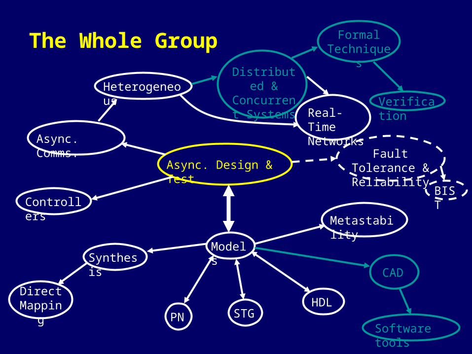
The Whole Group
Async. Design & Test
Controllers
Async. Comms.
Heterogeneous
PN STG
Models
HDL
BIST
Fault Tolerance & Reliability
Synthesis
Direct Mapping
Metastability
CAD
Software tools
Distributed & Concurrent Systems Verification
Formal Techniques
Real-Time Networks

MOVIE - “Model Visualisation for Asynchronous Circuit Design”
The project addresses the development of theoretical models and an associated set of algorithms and software tools for graphical representation and visualisation of highly complex asynchronous circuit behaviour. New tools will enable skilled designers to achieve greater quality and productivity, and greater confidence in their designs.
A few slides from DATE’03 …

Visualisation and Resolution of Coding
Conflicts in Asynchronous Circuit Design
A. Madalinski, V. Khomenko, A. Bystrov and A. Yakovlev
University of Newcastle upon Tyne
MOVIE Project

Motivation
• state coding is a necessary for implementability• manual vs. automatic resolution of coding conflicts
– automatic can produce sub-optimal solutions– manual crucial for finding good (low-latency,
compact & elegant) synthesis solutions• interactivity is good!• conflict complementary set (i.e. {b+,a-,b-,a+}) called
a ‘core’• select cores insert a signal to break the conflict.

Core selection: Height map
Core map Height map
csc1+

Signal insertion: an example
Core map Part of the solving process
csc1+
csc1-
Phase 1 Phase 2
888 CSC conflicts – 4 cores
BEhavioural Synthesis of Systems with heterogeneous Timing (BESST) supported by EPSRC at Newcastle University (project GR/R 16754)
Aim : The overall strategic goal of the project is generic methods and an associated set of software tools for synthesis of systems with heterogeneous timing --- primarily focused on self-timed controllers and interfaces.
Prof. Alex Yakovlev, Dr. Albert Koelmans,
Dr. Frank Burns, and Mr. Delong Shang
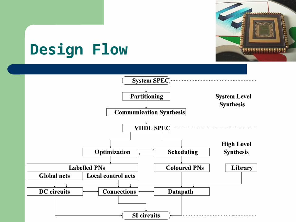
Design Flow

System Synthesis Method
A new method has been proposed. It is not a syntax-direct translation. It semantically translates a system specification from high level to an intermediate format, LPNs (Labelled Petri Net) and CPNs (Coloured Petri Net), and then directly maps the LPNs and CPNs to an SI (Speed Independent) circuit.
Some examples have been done using the method, such as DMA controller, and others.
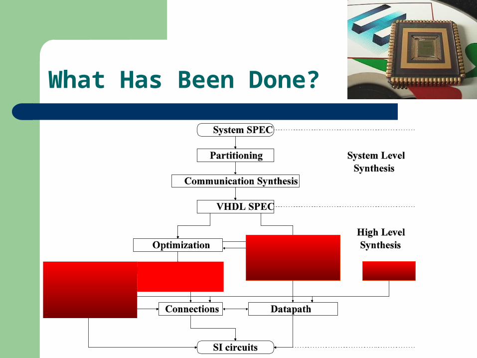
What Has Been Done?

Current and Future Work.
Currently more research is focused on optimization and scheduling, and will be focused on the system level synthesis, for example partitioning and communication synthesis.
More complex examples are being studied. Relative Timing (RT) techniques among
others will be introduced to improve performance.
STELLA: Synthesis and Testing of Low-Latency Asynchronous
Circuits
Prof. A. Yakovlev (PI)Dr. A. Bystrov
Prof. D. KinnimentDr. A. Koelmans
Dr. G. Russell
Jan. 2003 -- Dec. 2005
Aims and Objectives
• Develop the detailed implementation architecture of a low-latency controller with techniques for automated decomposition, synthesis and timing analysis (see e.g. CS-TR-743, CS-TR-754 – from ‘http://www.cs.ncl.ac.uk/’).
• Develop the main supporting structures for off-line testing, such as internal scanning, for a class of stuck-at, bridging and delay faults with minimum speed overheads (see e.g. CS-TR-746).
• Develop the detailed architecture for a snooper for on-line testing of self-timed structures with minimum area and power consumption overheads.
• Develop a demonstrator chip employing the testable low-latency methodology; the application area will be an on-chip communication adaptor.
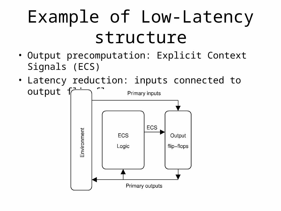
Example of Low-Latency structure
• Output precomputation: Explicit Context Signals (ECS)• Latency reduction: inputs connected to output flip-flops

Interfacing to standard CAD tools
• Maximum reuse of industrial CAD tools• Providing alternative solutions to the parts of the standard
design flow• Compilation of RTL specs and structural Verilog netlists
into asynchronous designs• Reuse of test-related standard CAD tools
Methods developed in the course of work will be implemented in software tools and interfaced to the industrial CAD toolkits (Cadence), acting as a performance and test oriented asynchronous design front-end.

COMFORT - "asynchronous COmmunication Mechanisms FOr Real-Time systems"
Objectives
• To study a range of asynchronous communication mechanisms (ACMs) that can be used in constructing (distributed and concurrent) systems with heterogeneous timing
• To develop hardware implementations for ACMs, (including self-timed circuits) for potential use in Systems-On-a-Chip (SOCs) and embedded (miniature, low power and EMC) applications

COHERENT - "COmputational HEteRogEneously timed NeTworks"
Objectives
• Development of a parameterised library of ACMs• Formal synthesis of multi-slot ACM algorithms• Develop RTNoC architecture (HETS)• Develop RTNoC design flow: functional spec, design,
simulation, analysis, prototyping, implementation and testing
• Test RTNoCs on real examples of control or vision systems; comparison with existing (centrally clocked) solutions

The Timing Modes Spectrum
Introduction and BackgroundA
nalo
gue
Asy
nchr
onou
s (s
elf-
timed
)
Sin
gle
cloc
k sy
nchr
onou
s
GA
LS
Het
erog
eneo
us
Non-sampled Sampled data
Continuous time Discrete time?
Par
alle
l
Mul
tiple
clo
ck
dom
ains
HE
TS
• Sequential and synchronous easier.• An intermediate solution GALS• Transfer of knowledge from the existing methods to the new solutions.
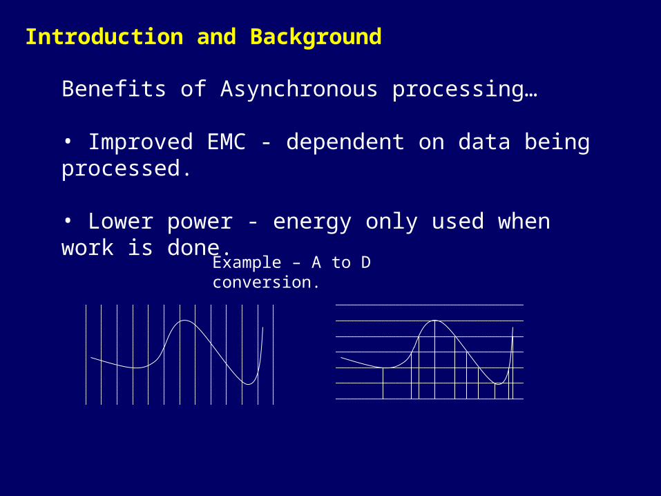
Benefits of Asynchronous processing…
• Improved EMC - dependent on data being processed.
• Lower power - energy only used when work is done.
Introduction and Background
Example – A to D conversion.
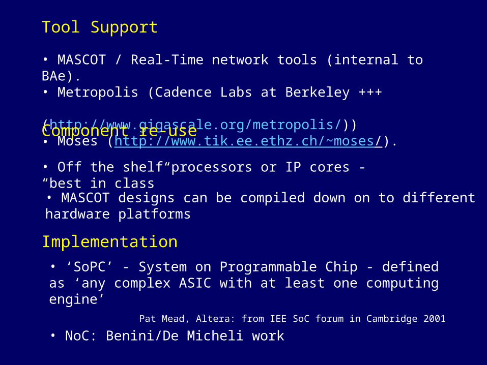
• MASCOT / Real-Time network tools (internal to BAe).• Metropolis (Cadence Labs at Berkeley +++
(http://www.gigascale.org/metropolis/))• Moses (http://www.tik.ee.ethz.ch/~moses/).
Tool Support
• Off the shelf processors or IP cores - “best in class”
• MASCOT designs can be compiled down on to different hardware platforms
Component re-use
• ‘SoPC’ - System on Programmable Chip - defined as ‘any complex ASIC with at least one computing engine’
Pat Mead, Altera: from IEE SoC forum in Cambridge 2001
• NoC: Benini/De Micheli work
Implementation

NoC – Network on Chip
• Large existing knowledge base.
• Philips ‘ethernet on chip’.
• Current networks are synchronous – cannot handle non-synchronous cores – like self-timed.
• Global chip communication – increased power consumption.
• Good for non-deterministic data communication.
• Side step the synchronization and global clock issues.
• Not suitable for Real-Time applications.

Baseline: Architectural aspect
• Real-time networks and MASCOT approach – from RSRE/Phillips(67), BAe/Simpson(86) – for software systems– high time heterogeneity but relatively low speed
• Globally-Asynchronous-Locally-Synchronous (GALS) – Chapiro(84), Muttersbach(00), Ginosar(00) – for VLSI circuits– high speed but very limited time heterogeneity

Heterogeneously Timed Nets (hets)(based on MASCOT standard symbols)
A1 C1
A3
A4
A2
C3
C2

Hets
A1 C1
A3
A4
A2
C3
C2
Time/event/data-drivenData processing elements(active)

Hets
A1 C1
A3
A4
A2
C3
C2
Data communication elements(passive) - ACMs

Asynchronous data communications
process 1 shared
memory process 2
writer reader
writer time domain reader time domain
Level of asynchrony is defined by WRITE and READ rules
Processes are single threads of execution.
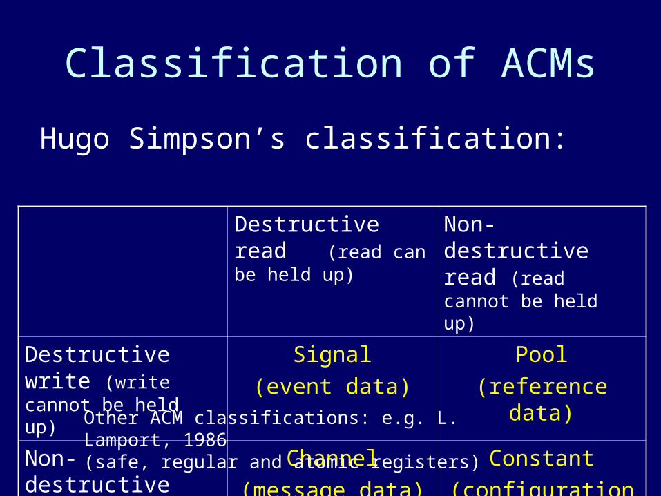
Classification of ACMs
Hugo Simpson’s classification:
Destructive read (read can be held up)
Non-destructive read (read cannot be held up)
Destructive write (write cannot be held up)
Signal
(event data)
Pool
(reference data)
Non-destructive write (write can be held up)
Channel
(message data)
Constant
(configuration data)
Other ACM classifications: e.g. L. Lamport, 1986 (safe, regular and atomic registers)

Difficulty with Simpson’s classification
• Destructive/Non-destructive does not intuitively imply temporal, Wait/No-wait division:
– Destructive write cannot wait – Destructive read can wait
• There is symmetry between Pool and Channel but no symmetry between Signal and Constant

Petri net capture of Simpson’s protocols
Signalnon-destr write empty
full
destr write
non-destr write
empty
full
destr read
non-destr write
empty
full
full
destr write non-destr read
destr read
ConstantChannel
Pool
non-destr read
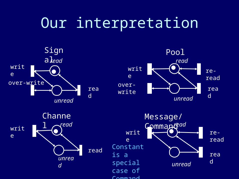
Our interpretation
Signal
writeread
unread
over-writeread
unread
writeread
unreadread
Message/CommandChannel
Pool
writeread
re-read
read
unread
over-write
write re-read
read
read
Constant is a special case of Command

Our interpretation
Signal
writeread
unread
over-writeread
unread
writeread
unreadread
Message/CommandChannel
Pool
writeread
re-read
read
unread
over-write
write re-read
read
read
Busy Writer
Lazy Writer
Busy ReaderLazy Reader
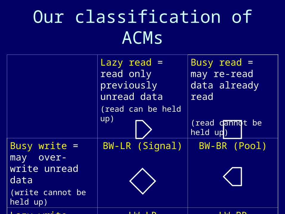
Our classification of ACMs
Lazy read = read only previously unread data(read can be held up)
Busy read = may re-read data already read
(read cannot be held up)
Busy write = may over-write unread data(write cannot be held up)
BW-LR (Signal) BW-BR (Pool)
Lazy write = write only if previous read data(write can be held up)
LW-LR (Channel) LW-BR (Command)

Signal vs Pool
Pool
Real time 1 (busy domain)
Real time 2 (busy domain)
Signal
Real time (busy domain)
Data-driven (lazy domain)
Low Power!

Sample algorithms
wr: write slot n;
w0: l:=n;
w1: n:=¬(l,r);
r0: r:=l;
rd: read slot r;
wr: write slot w;
w0: w:=¬r;
r0: r:=¬r;
rd: wait until w¬=r
read slot r;
Signal – with 2 slots – conditionally asynchronous
Pool – with 3 slots – fully asynchronous

- Multiple slots:
No temporal independence with only one slot.(There will always be situations when both processes clash in time on the one data slot).
- Slot:
Shared memory for one item of data
What is a slot?
- Capacity
Not to be confused with the number of slots. It takes a minimum of 3 slots to make a capacity 1 pool.

Data PropertiesCoherence
Write: ‘07:57’; ‘07:58’; ‘07:59’; ‘08:00’; ‘08:01’; ‘08:02’; ‘08:03’;
Read: ‘07:57’; ‘07:59’;‘07:00’; ‘08:02’;
Freshness
Write: ‘07:57’; ‘07:58’; ‘07:59’; ‘08:00’; ‘08:01’; ‘08:02’; ‘08:03’;
Read: ‘07:57’; ‘07:58’; ‘08:02’;
Sequence
Write: ‘07:57’; ‘07:58’; ‘07:59’; ‘08:00’; ‘08:01’; ‘08:02’; ‘08:03’;
Read: ‘07:57’; ‘07:59’;‘07:58’; ‘08:02’;

SIGNAL: Data latency
If a reader cycle immediately follows a writer cyclewhat data does it get?
Write X post
Does the reader read X?

SIGNAL: Data latency
Write X post
w=0r=0
write slot w;w := not r;
r := not r;wait until w¬=rread slot r;
Write slot 0
w:=not r = 1
pre
r:=not r = 1
w==rtherefore
made to wait
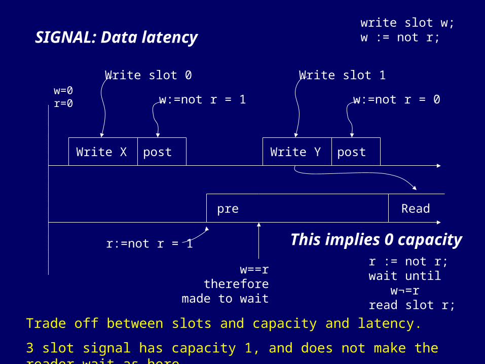
SIGNAL: Data latency
w=0r=0
write slot w;w := not r;
r := not r;wait until w¬=rread slot r;
Write X post
Write slot 0
w:=not r = 1
pre
r:=not r = 1
w==rtherefore
made to wait
Write Y post
Write slot 1
w:=not r = 0
Read
This implies 0 capacity
Trade off between slots and capacity and latency.
3 slot signal has capacity 1, and does not make the reader wait as here.
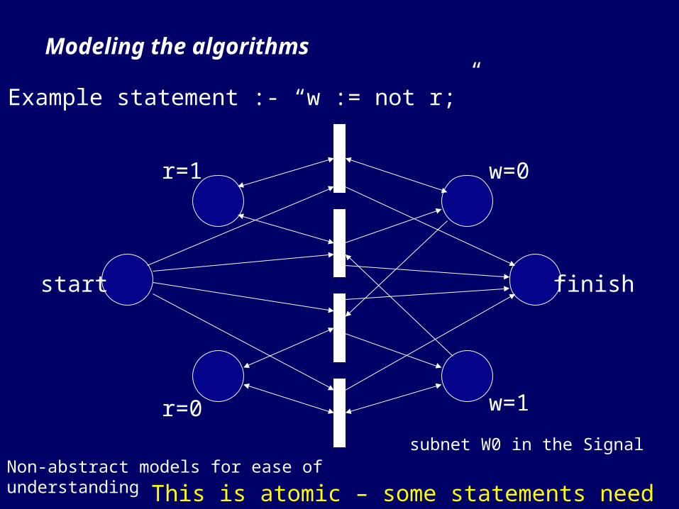
Modeling the algorithms
Example statement :- “w := not r;”
r=1
r=0
w=0
w=1
finishstart
subnet W0 in the SignalNon-abstract models for ease of understanding
This is atomic – some statements need to be 2 stage

Modeling the algorithms
W0 subnet
write subnet
read subnet
R0 subnet
w=0/1
r=0/1
Slot_0/1read/unread
setting
referencing

Sub-models and the ‘enable’ place
write post
Write is set to fresh and validother slot is set to not fresh
write end fresh and validsub-model
This should appear as an atomic action to the other process

Sub-models and the ‘enable’ place
write end testingsub-model
enable
part of the reader model

MetastabilityActive clock edge
time
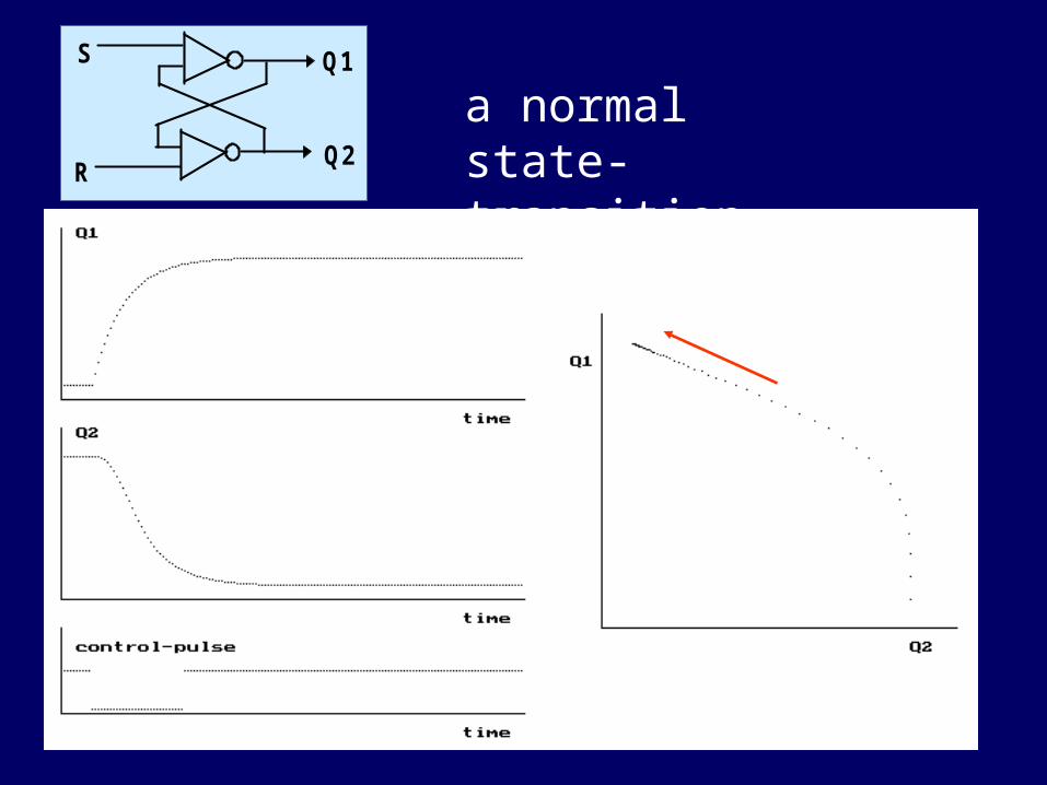
Q1
Q2
S
R
a normal state-transition
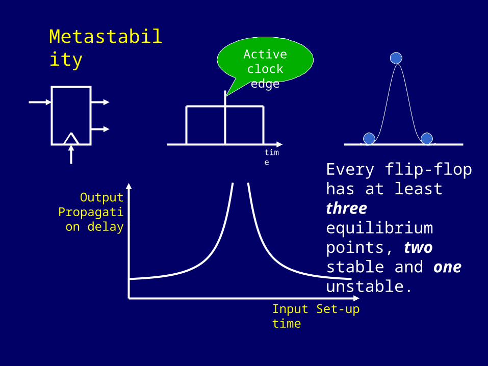
MetastabilityActive clock edge
time
Input Set-up time
Output Propagation
delay
Every flip-flop has at least three equilibrium points, two stable and one unstable.

Metastable transients
3
1
3
1
3
1
13

Keep away from data path!
MetastabilityActive clock edge
time
Input Set-up time
Output Propagation
delay
M
0
1
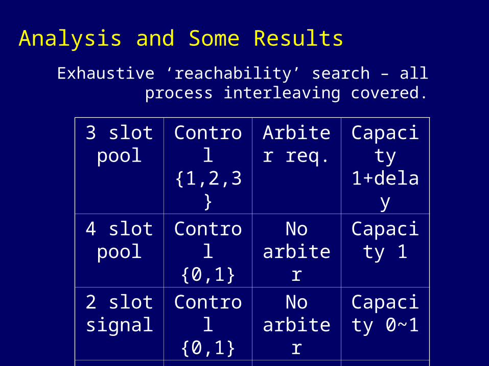
Analysis and Some Results
Exhaustive ‘reachability’ search – all process interleaving covered.
3 slot pool
Control {1,2,3}
Arbiter req.
Capacity 1+delay
4 slot pool
Control {0,1}
No arbiter
Capacity 1
2 slot signal
Control {0,1}
No arbiter
Capacity 0~1
3 slot signal
Control {1,2,3}
No arbiter
Capacity 1
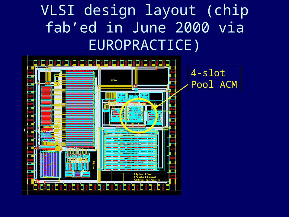
VLSI design layout (chip fab’ed in June 2000 via EUROPRACTICE)
4-slot Pool ACM
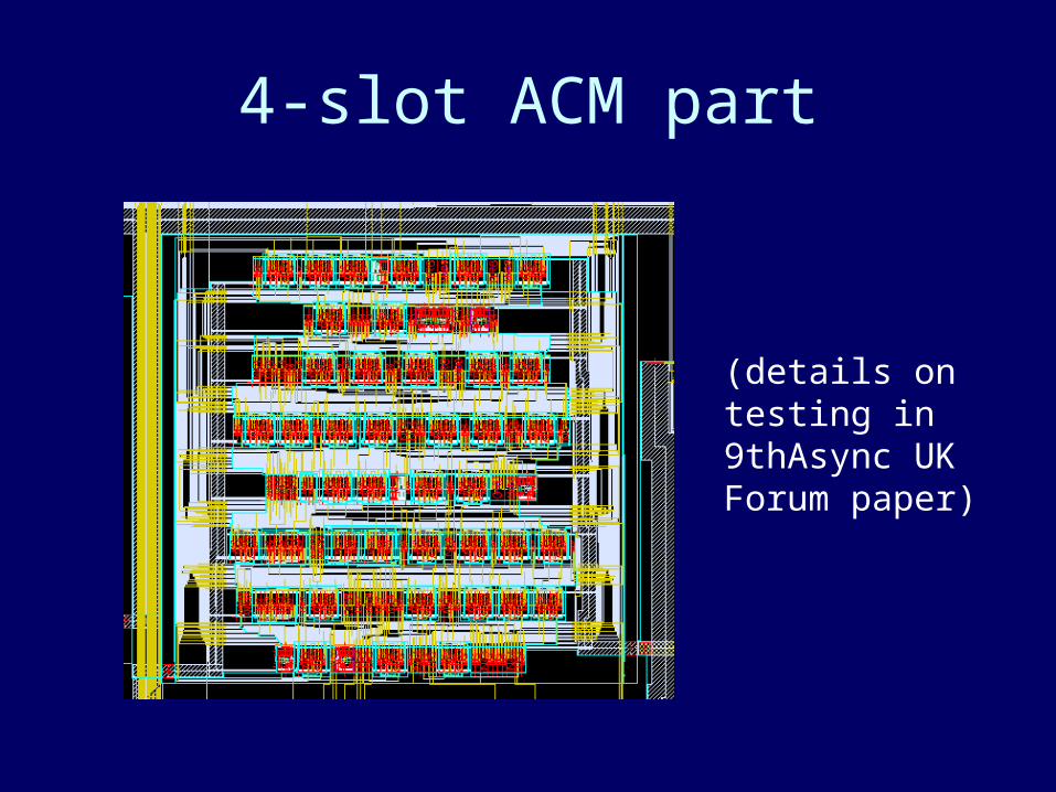
4-slot ACM part
(details on testing in 9thAsync UK Forum paper)
Applications
Sensor networks
• Condition based maintenance
Control systems
• Broom balancer.
Distributed CCTV
• Advisor EU Project.
In car network
• simple RC oscillator – vast clock range with temp.

The Whole Group
MOVIE
BESST
STELLA
COMFORTAsync. Comms.
Metastability
COHERENT
Heterogeneous
Open ProblemsConclusion

Open questions
Analysis of dynamic systems with ACMs in.
Testing intermittent faults, online-testing (e.g. cross talk).
Folding of Petri Nets
• Synthesis from partial orders.

Acknowledgements
More info on team and projects
Leader: Alex Yakovlev.
Academics: Graeme Chester , Tony Davies, David Kinniment, Albert Koelmans, Maciej Koutny, Gordon Russell, Sergio Velastin.
Collaborators: Eric Campbell, Hugo Simpson, +++.
Researchers: Frank Burns, Alex Bystrov, David Fraser, Marta Pietkiewicz-Koutny, Delong Shang, Fei Xia.
Students: Fei Hao, Victor Khomenko, Agnes Madalinski, Danil Sokolov, Maria Valera, +++.