Embed Size (px)
Citation preview

All Rights Reserved by Japan Virtual Microcontroller Initiative / vECU-MBD WG The 15th Car-Electronics Research Workshop
Trial of multiple ECU co-simulation and fault injection
using virtual ECU
- vECU-MBD WG activity example introduction -
Japan Virtual Microcontroller Initiative
vECU-MBD WG
Yoshihiro Miyazaki Technology Development Div. Hitachi Automotive Systems, Ltd.
Takashi Abe Basis Electronics R&D Div. Denso Corp.
July 14, 2014
The 15th Car-Electronics Research Workshop
@ Jidosha Kaikan (Tokyo / Ichigaya)
1

All Rights Reserved by Japan Virtual Microcontroller Initiative / vECU-MBD WG The 15th Car-Electronics Research Workshop
Today's presentation contents
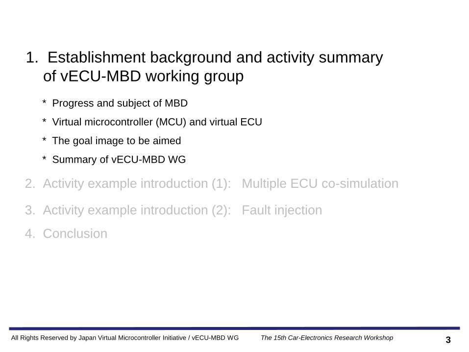
1. Establishment background and activity summary of vECU-MBD
working group
2. Activity example introduction (1): Multiple ECU co-simulation
3. Activity example introduction (2): Fault injection
4. Conclusion
2
[Notes]
ECU: Electronic Control Unit
vECU: Virtual ECU
MBD: Model Based Development
All Rights Reserved by Japan Virtual Microcontroller Initiative / vECU-MBD WG The 15th Car-Electronics Research Workshop
1. Establishment background and activity summary
of vECU-MBD working group
3
* Progress and subject of MBD
* Virtual microcontroller (MCU) and virtual ECU
* The goal image to be aimed
* Summary of vECU-MBD WG
2. Activity example introduction (1): Multiple ECU co-simulation
3. Activity example introduction (2): Fault injection
4. Conclusion

All Rights Reserved by Japan Virtual Microcontroller Initiative / vECU-MBD WG The 15th Car-Electronics Research Workshop
Progress of the MBD utilization
4
Utilize model for result prediction in later development process
Man-hour
time
Background of Automotive Product Development
• Development of high-functionality & high-quality product to respond product
performance
• Shortening turn-around time for early release to the market
Increased load to S/W development engineer by electronic control of automotive
part
Test &verification Design &
implementation
Additional Spec.
design
Result prediction
of additional
Spec. is difficult
• Engine and break etc., i.e individual function is getting large & complex
• Assigning adjustment among functions is getting complex by network connection of
functions
Man-hour increase
In lower process
(implementation,
test, verification)
Can't they shift to
upper process
(system design,
specification
design) ?
Application of MBD for electronic control system is expanding
From:
All Rights Reserved by Japan Virtual Microcontroller Initiative / vECU-MBD WG The 15th Car-Electronics Research Workshop
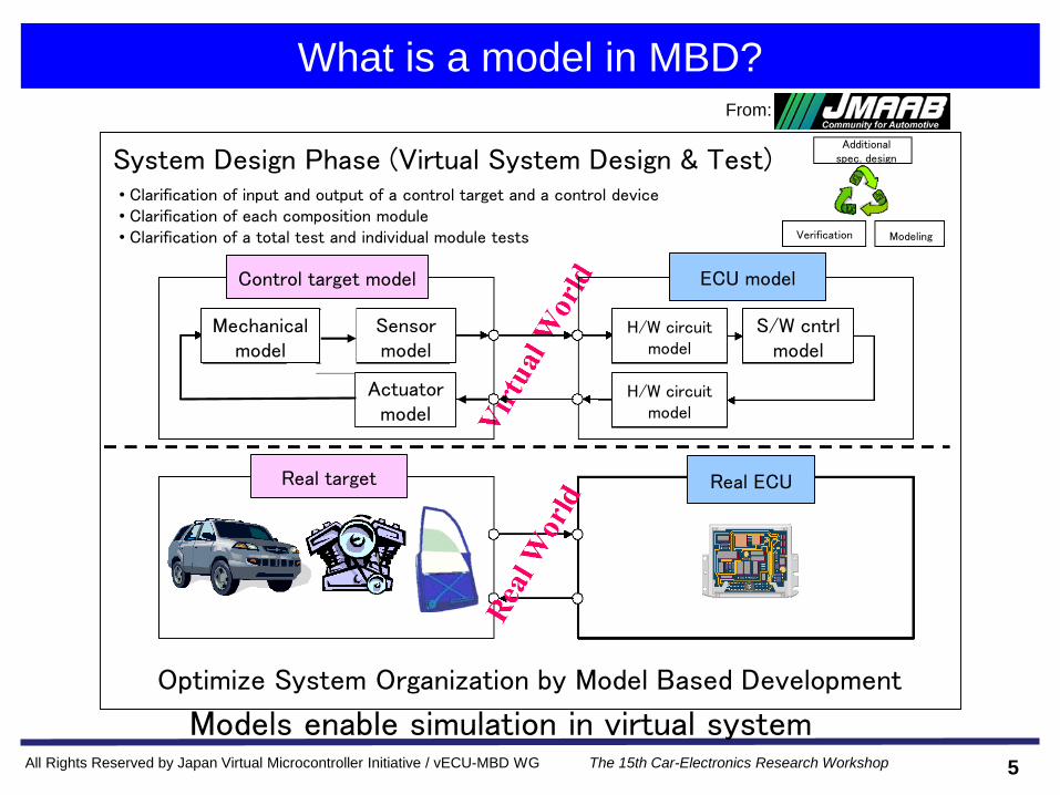
What is a model in MBD?
5
Models enable simulation in virtual system
From:
Optimize System Organization by Model Based Development
ECU model
Real ECU
S/W cntrlmodel
H/W circuit model
H/W circuit model
Sensor model
Actuatormodel
Mechanical model
Control target model
Real target
System Design Phase (Virtual System Design & Test) • Clarification of input and output of a control target and a control device• Clarification of each composition module• Clarification of a total test and individual module tests
Additionalspec. design
ModelingVerification

All Rights Reserved by Japan Virtual Microcontroller Initiative / vECU-MBD WG The 15th Car-Electronics Research Workshop
Subject of a future system test
6
HILSB-CAN
F-CAN
In-Vehicle Test
Large scale HILS Test of a whole-vehicle
Early detection of software errors is difficult, because test of application & platform & network is executed only after completion of real unit.
Electronic controlsystem
In-vehicleLAN
High-performance
FusionHigh-
technology
Complicated
Enginecontrol
Brakecontrol
Bodycontrol
Steeringcontrol
Aroundmonitor
All Rights Reserved by Japan Virtual Microcontroller Initiative / vECU-MBD WG The 15th Car-Electronics Research Workshop
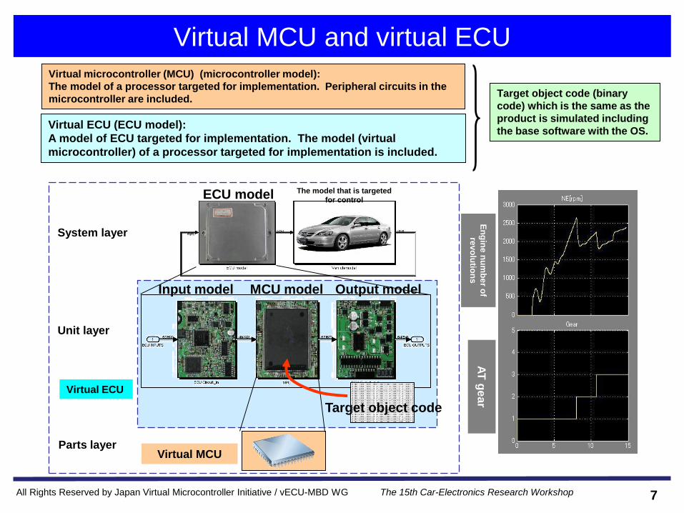
Virtual MCU and virtual ECU
7
Virtual ECU (ECU model):
A model of ECU targeted for implementation. The model (virtual
microcontroller) of a processor targeted for implementation is included.
The model that is targeted
for controlECU model
Input model Output modelMCU model
System layer
Unit layer
Parts layerVirtual MCU
Target object code
En
gin
e n
um
be
r of
revo
lutio
ns
AT
ge
ar
Virtual ECU
Virtual microcontroller (MCU) (microcontroller model):
The model of a processor targeted for implementation. Peripheral circuits in the
microcontroller are included.Target object code (binary
code) which is the same as the
product is simulated including
the base software with the OS.

All Rights Reserved by Japan Virtual Microcontroller Initiative / vECU-MBD WG The 15th Car-Electronics Research Workshop
How to use virtual ECU
8
Goal process
Demand
side
Supply
side
Specifications
Parts
(ECU)
Demand
side
Supply
side
Specifications +
Executablerequirement model
Demand
side
Supply
side
Parts
(ECU)
Specifications +
Executable requirement model
To be used as an executable parts model
Parts
(ECU)
The
past
Now
In the
future
Executable
parts model
Virtual ECU
Final Verification
Recent process change

All Rights Reserved by Japan Virtual Microcontroller Initiative / vECU-MBD WG The 15th Car-Electronics Research Workshop
HILS and virtual HILS
9
HILS
01001010
01101011
11101010
01010111
* ・ ... ...
HILS device
Vehicle model
ECU(Real machine)
Software
(binary code)
HILS (Hardware-in-the-loop simulation))
■ Structure: Real ECU+ plant model ■ Feature
- Verify the same binary code as a product
- Verify software of a real system
■ Demerit
Limitation of place, target environment connection,
reproducibility and observability, fault injection. etc.
Virtual HILS
■ Structure: Virtual ECU+ plant model ■ Feature
-Verify the same binary code as a product
-Verify software almost equivalent as a real system
- Real machine-less (Real machine is unnecessary and
test can be done before completion of the real
machine)
- Demerits of HILS (left) are solved. (place, target
environment connection, reproducibility and
observability, fault injection, etc.)
- Remote usage or parallel execution can be done on
cloud
Virtual HILS
Plant model
(vehicle model)
Virtual ECU
SimulatorCo-sim
Microcontroller model
(virtual microcontroller)
Controller model (virtual ECU)
Software
(binary code)
Simulator
Now Goal

All Rights Reserved by Japan Virtual Microcontroller Initiative / vECU-MBD WG The 15th Car-Electronics Research Workshop
The goal image to be aimed
10
To apply virtual ECU in each development process phase→ Shortening the right side of V-shape development process
ComponentVerification
Mass ProductionRequirement Design
S/W Detail Design
Spec. Design
Implementation
In-VehicleVerification
Demand Side
Supply Side
Demand Side
Supply Side
Shortening
Component-lessDebug & Verification
Vehicle-lessDebug & Verification
Virtual MCU
Virtual ECU/Virtual HILS
Code
Code
ECU Internal Requirement Model
System Requirement Model
Software Requirement Model
ECU Requirement Model
コード
Virtual System/Virtual Full-Vehicle Simulation
コード
Shortening
All Rights Reserved by Japan Virtual Microcontroller Initiative / vECU-MBD WG The 15th Car-Electronics Research Workshop
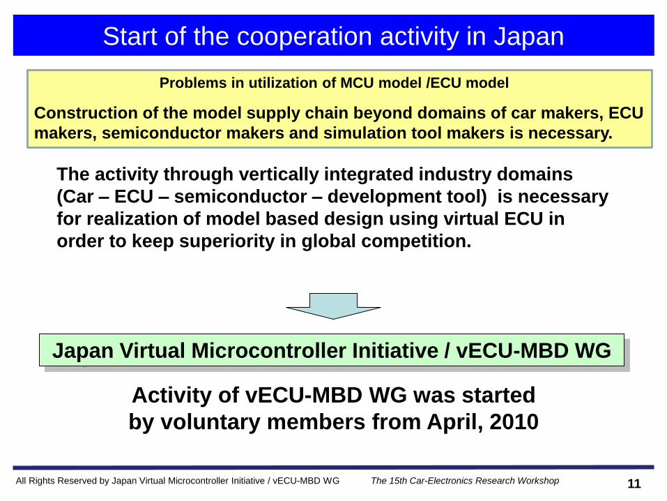
Start of the cooperation activity in Japan
11
Activity of vECU-MBD WG was started
by voluntary members from April, 2010
Japan Virtual Microcontroller Initiative / vECU-MBD WG
The activity through vertically integrated industry domains
(Car – ECU – semiconductor – development tool) is necessary
for realization of model based design using virtual ECU in
order to keep superiority in global competition.
Problems in utilization of MCU model /ECU model
Construction of the model supply chain beyond domains of car makers, ECU
makers, semiconductor makers and simulation tool makers is necessary.

All Rights Reserved by Japan Virtual Microcontroller Initiative / vECU-MBD WG The 15th Car-Electronics Research Workshop
Outline of vECU-MBD WG
12
[member]
Honda R&D Co., Ltd., Mazda Motor Corporation, Nissan Motor Co., Ltd., Aisin Seiki Co., Ltd, Calsonic Kansei
Corporation, DENSO Corporation, Fujitsu Ten Ltd., Hitachi, Ltd., Hitachi Automotive Systems, Ltd., Hitachi
Industry & Control Solutions, Ltd., IBM Japan, Ltd, OMRON Automotive Electronics Co., Toyota Technical
Development Corporation, Renesas Electronics Corporation, Spansion Innovates Ltd., TOSHIBA CORPORATION,
ETAS K.K., Nihon Synopsys G.K, GAIO TECHNOLOGY Co., Ltd, Australian Semiconductor Technology Company
K.K., TOOL Corporation, LINKPORT Co. ,Ltd., dSPACE Japan K.K., Qualiarc Technology Solutions, Inc., Japan
Automobile Research Institute(JARI), Semiconductor Technology Academic Research Center (STARC), Institute
of Systems, Information Technologies and Nanotechnologies (ISIT)(Total 27 organizations) [in no particular order] (June, 2014)
◆ Feature: Cooperation activity which crosses vertically through industry
◆ Objectives: To promote application of MBD environment using virtual ECU
◆ Participating members:
Car makers, ECU suppliers, semiconductor vendors, tool vendors, research institutions and
universities
◆ Activity history: April 2010~present
◆ URL: http://www.vecu-mbd.org/en/ (Japanese ver.: http://www.vecu-mbd.org/)
◆ Main achievement:
(1)User support guide to consider introduction & Glossary
(2)Experimental example (system integration and evaluation)
◆ Important activity theme of 2013FY:
(1) multiple ECU co-simulation, (2) fault injection test

All Rights Reserved by Japan Virtual Microcontroller Initiative / vECU-MBD WG The 15th Car-Electronics Research Workshop
Activity Roadmap
13
◆Considering importance and difficulty, three activity phases have been planned. TF activities started from 2011.◆2013FY~: Model supply chain TF were closed because its purpose were almost achieved. Virtual HILS TF
were newly established.
Phase1(2011FY~ 2012FY)
Phase2(2013FY~20xxFY)
Phase3(20xxFY~20yyFY)
Model Supply Chain TF
Standardization and mechanism for model
distribution
—Model development of use case
—Definition of development process and
model supply chain business process
Virtual HILS TF
(TBD): Cloud supporting, co-operation in
business field supporting
Basic Technology Environment for High Efficiency Large Scale, High Availability
Microcontroller Model TF
Standardization in business field, Supporting
model and tool
-Fault injection
-Interface model connecting multiple ECUs
-Co-simulation of multiple ECUs

All Rights Reserved by Japan Virtual Microcontroller Initiative / vECU-MBD WG The 15th Car-Electronics Research Workshop
The WG activity system
14
vECU-MBD WG
Model supply chain TF
Representative: Murakami (ISIT, Kyushu University)
Secretariat: ISIT/STARC
Meeting frequency: Three months / time
Microcontroller model TF
Leader: Shimada (Honda R & D)
Sub-leader: Miyazaki (Hitachi Automotive Systems)
Secretariat: ISIT
Meeting frequency: One month / time
Leader: Yoshino (Fujitsu semi-conductor)
Sub-leader: Komatsu (IBM JAPAN)
Okazaki (Renesas Electronics)
Secretariat: STARC
Meeting frequency: One month / time
vECU-MBD WG
Virtual HILS TF
Microcontroller model TF
Leader: Miyazaki (Hitachi Automotive Systems)
Sub-leader: Abe (Denso)
Secretariat: ISIT
Meeting frequency: One month / time
Leader: Yoshino (Spansion Innovates )
Sub-leader: Komatsu (IBM JAPAN)
Okazaki (Renesas Electronics)
Secretariat: STARC
Meeting frequency: One month / time
Phase 1 (... 2012) Phase 2 (2013 ...)
Representative: Murakami (ISIT, Kyushu University)
Secretariat: ISIT/STARC
Meeting frequency: Three months / time

All Rights Reserved by Japan Virtual Microcontroller Initiative / vECU-MBD WG The 15th Car-Electronics Research Workshop
WG Activity Scene
Activity scene of the 18th vECU-MBD WG meeting June 20,2014@Semiconductor Technology Academic Research Center (STARC)
15

All Rights Reserved by Japan Virtual Microcontroller Initiative / vECU-MBD WG The 15th Car-Electronics Research Workshop
Main activity theme of virtual HILS TF
16
◆ Background
~2012FY: Main activity was enlightenment.
2013FY ~: Main activity was shifted to standardization in the industry domain, and
correspondence of models and tools.
◆ Main activity theme
(1) multiple ECU co-simulation (and interface model among multiple ECUs)
(2) fault injection
◆ Activity contents
(1) Standardization and trial for easy realization of "one virtual car simulation"
The use case in the car maker: one virtual car simulation
Standardization of the interface model among multiple ECUs
-> To make combination of multiple ECUs easy
CAN bus model examined from 2012FY is utilized
(2) Standardization and trial for easy realization of "virtual fault injection test"
Trial of fault injection test to MCU model and peripheral models
Proposal of requirement specifications standardization (plan) of fault injection
Note 1: Fault mode, timing, and environmental condition were limited in case of conventional real machines. But they can
be arranged easily in case of virtual fault injection test. There is an issue how large test coverage should be considered.
This WG works on requirement specifications standardization of virtual fault injection test.
Note 2: Virtual HILS TF cooperates with microcontroller model TF for solving technical issues.

All Rights Reserved by Japan Virtual Microcontroller Initiative / vECU-MBD WG The 15th Car-Electronics Research Workshop
2. Activity example introduction (1): Multiple ECU co-simulation
17
- Outline of multiple ECU co-simulation
- Structure of the experimental example (multiple ECUs system)
- vECU-CAN bus model
- Operation of the experimental example (multiple ECUs system)
- Summary
3. Activity example introduction (2): fault injection
4. Conclusion
1. Establishment background and activity summary of vECU-MBD working
group
All Rights Reserved by Japan Virtual Microcontroller Initiative / vECU-MBD WG The 15th Car-Electronics Research Workshop
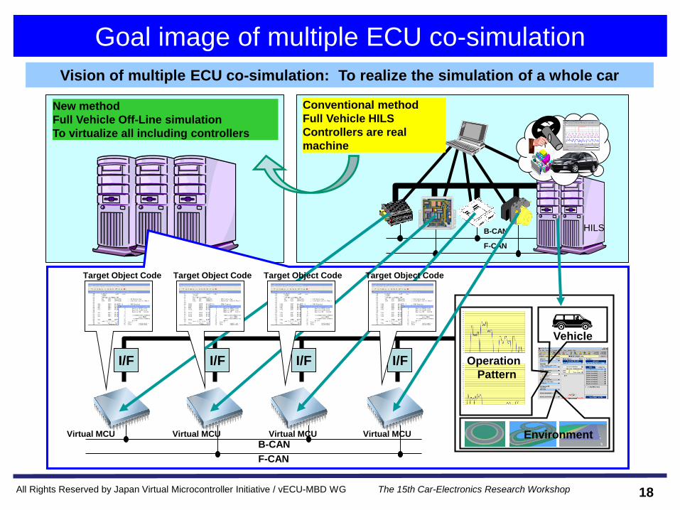
Goal image of multiple ECU co-simulation
18
HILSB-CAN
F-CAN
B-CAN
F-CAN
Vehicle
Environment
Operation
PatternI/F I/F I/F I/F
Virtual MCU
Target Object Code Target Object Code Target Object Code Target Object Code
Virtual MCU Virtual MCU Virtual MCU
Conventional method
Full Vehicle HILS
Controllers are real
machine
New method
Full Vehicle Off-Line simulation
To virtualize all including controllers
Vision of multiple ECU co-simulation: To realize the simulation of a whole car

All Rights Reserved by Japan Virtual Microcontroller Initiative / vECU-MBD WG The 15th Car-Electronics Research Workshop
Goal image of multiple ECU co-simulation
19
System constitution of multiple ECU cooperation simulation
FI/AT
ECU
ADAS
ECU
EPS
ECU
Power
Window
ECU
Engine
Model
T/M
ModelBraking system
Model
EPS G/B ASSY
Model
Head Light
Model
Power Window /Mirror
Model
Wiper model
Driving Position
Model
Door model
Vehicle model
[plant model]
Car behavior model
[controller model]
ECU model
ESC
ECU
Chassis
system
ECU
Body
system
ECU
Engine
system
ECU
Communications bus model (e.g.:) CAN bus model)
All Rights Reserved by Japan Virtual Microcontroller Initiative / vECU-MBD WG The 15th Car-Electronics Research Workshop
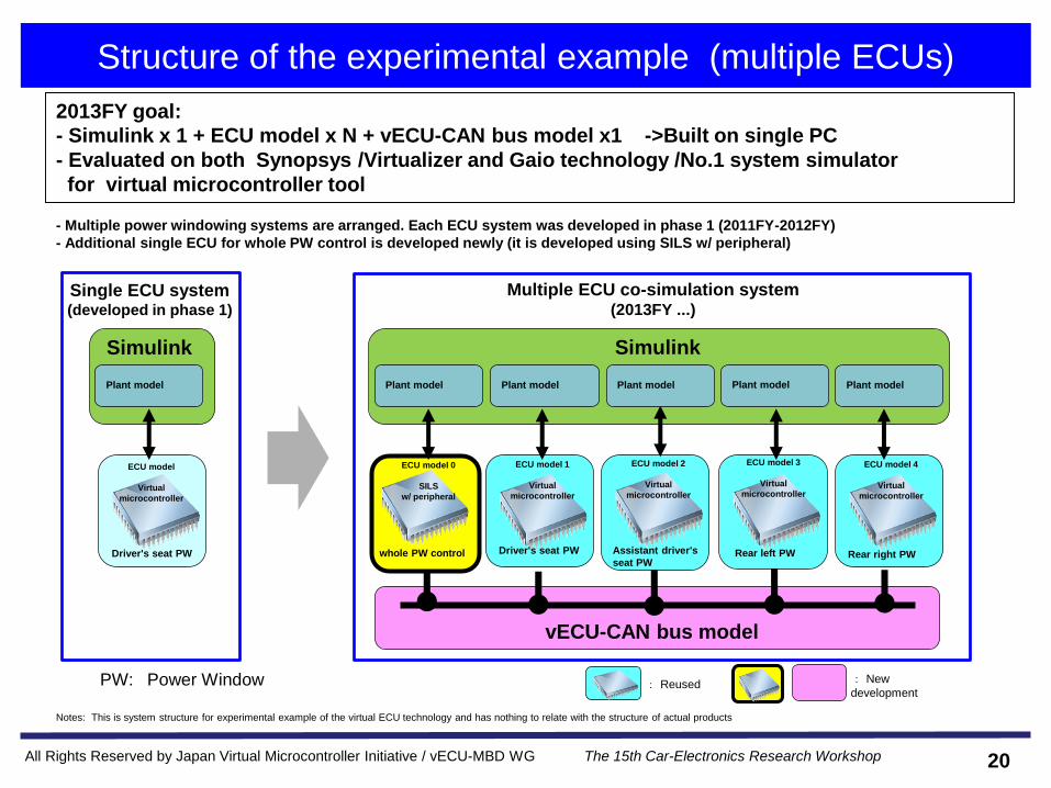
Structure of the experimental example (multiple ECUs)
20
- Multiple power windowing systems are arranged. Each ECU system was developed in phase 1 (2011FY-2012FY)
- Additional single ECU for whole PW control is developed newly (it is developed using SILS w/ peripheral)
: New
development: ReusedPW: Power Window
ECU model 1
Virtual
microcontroller
vECU-CAN bus model
ECU model 2
Virtual
microcontroller
ECU model 0
SILS
w/ peripheral
ECU model 3
Virtual
microcontroller
ECU model 4
Virtual
microcontroller
Driver's seat PW Assistant driver's
seat PWRear left PW Rear right PWwhole PW control
Plant model Plant model Plant model Plant modelPlant model
Simulink
ECU model
Virtual
microcontroller
Driver's seat PW
Plant model
Simulink
Multiple ECU co-simulation system (2013FY ...)
Single ECU system(developed in phase 1)
2013FY goal:
- Simulink x 1 + ECU model x N + vECU-CAN bus model x1 ->Built on single PC
- Evaluated on both Synopsys /Virtualizer and Gaio technology /No.1 system simulator
for virtual microcontroller tool
Notes: This is system structure for experimental example of the virtual ECU technology and has nothing to relate with the structure of actual products
All Rights Reserved by Japan Virtual Microcontroller Initiative / vECU-MBD WG The 15th Car-Electronics Research Workshop
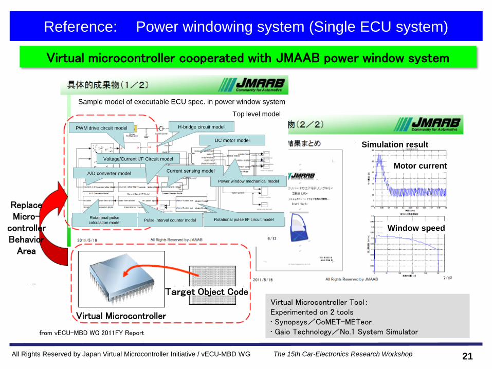
Reference: Power windowing system (Single ECU system)
21
Virtual microcontroller cooperated with JMAAB power window system
from vECU-MBD WG 2011FY Report
Virtual Microcontroller Tool:Experimented on 2 tools• Synopsys/CoMET-METeor• Gaio Technology/No.1 System Simulator
Target Object Code
Virtual Microcontroller
ReplaceMicro-
controllerBehavior
Area
Sample model of executable ECU spec. in power window system
Top level model
PWM drive circuit model H-bridge circuit model
DC motor model
Power window mechanical model
Current sensing modelA/D converter model
Voltage/Current I/F Circuit model
Rotational pulse
calculation modelPulse interval counter model Rotational pulse I/F circuit model
Simulation result
Motor current
Window speed
All Rights Reserved by Japan Virtual Microcontroller Initiative / vECU-MBD WG The 15th Car-Electronics Research Workshop
Communication interface model among multiple ECUs
22
◆ Background
* The standardization of interface model among multiple ECUs is not yet
achieved because generalization is difficult.
* This WG planned to investigate standard specifications (proposal) of the
communication interface model used frequently in automotive control use
and to correspond to CAN bus interface as the first step.
* As for CAN bus interfaces, standardization is desirable because it is used
widely for communication among multiple ECUs. Its standardization will
make it easy to connect multiple ECU models of the different suppliers.
Standard specification of the CAN bus interface model has been proposed
by vECU-MBD WG.
The name of the proposed CAN bus interface model is the following.
"vECU-CAN bus model"

All Rights Reserved by Japan Virtual Microcontroller Initiative / vECU-MBD WG The 15th Car-Electronics Research Workshop
Overview of vECU-CAN bus model
23
Name vECU-CAN bus model _ message level vECU-CAN bus model _ bit level
Feature High speed version Highly accurate version
General
structure
Timing precision
Demand function * The arbitration is controlled by a message
unit
* CAN2.0b based
* The arbitration is controlled by a bit unit
Use case * Simulation of virtual car one whole car
* Software function verification
* Fault injection (message level timing)
* CAN bus competing behavior evaluation
* Fault injection (bit level timing)
MCU model
CPU
CAN
Tx
Value send/receive
Rx
Value send/receive
ECU 1MCU model
CPU
CAN
ECU n
* * *
CAN Bus
Message level transfer
Tx Rx
Message level
Microcontroller
modelCPU
CAN
Tx
Value send/receive
Rx
Value send/receive
ECU 1Microcontroller
modelCPU
CAN
ECU n
* * *
CAN Bus
Bit level transfer
Tx Rx
Bit level
Models with two kinds of timing accuracy are defined in order to use them in various use cases.
"vECU-CAN bus model _ message level" was constructed and evaluated in 2013FY.

All Rights Reserved by Japan Virtual Microcontroller Initiative / vECU-MBD WG The 15th Car-Electronics Research Workshop
Implementation structure of vECU-CAN bus model message level
24
vECU-CAN BUS
Adapter
CAN Controller
CPU Simulator
Network
Scheduler
Inter-process
communication
TCP/IP
vECUCAN-API
Socket
Buffer +Adapter
Adapter
CAN Controller
CPU Simulator
Inter-process
communication
TCP/IP
)
vECUCAN-API
Socket
Buffer +Adapter
Inter-process
communicationInter-process
communication
SocketSocketSocket IF can be omitted
In case of single PC
Standard API
Standard Socket IF
Developed by
vECU-MBD WG
Existing model
can be used.
To be connected
via standard API
(or standard
Socket IF)
Virtual MCU Virtual MCU
Simulink (including plant model)
Features:
(1) Standard API connectable with existing models of the virtual microcontroller tool
(2) Co-simulation with Simulink (existing properties can be used)
(3) Expansion interface to support simulation on multiple PCs (standard Socket IF)
Existing
property
can be used
All Rights Reserved by Japan Virtual Microcontroller Initiative / vECU-MBD WG The 15th Car-Electronics Research Workshop
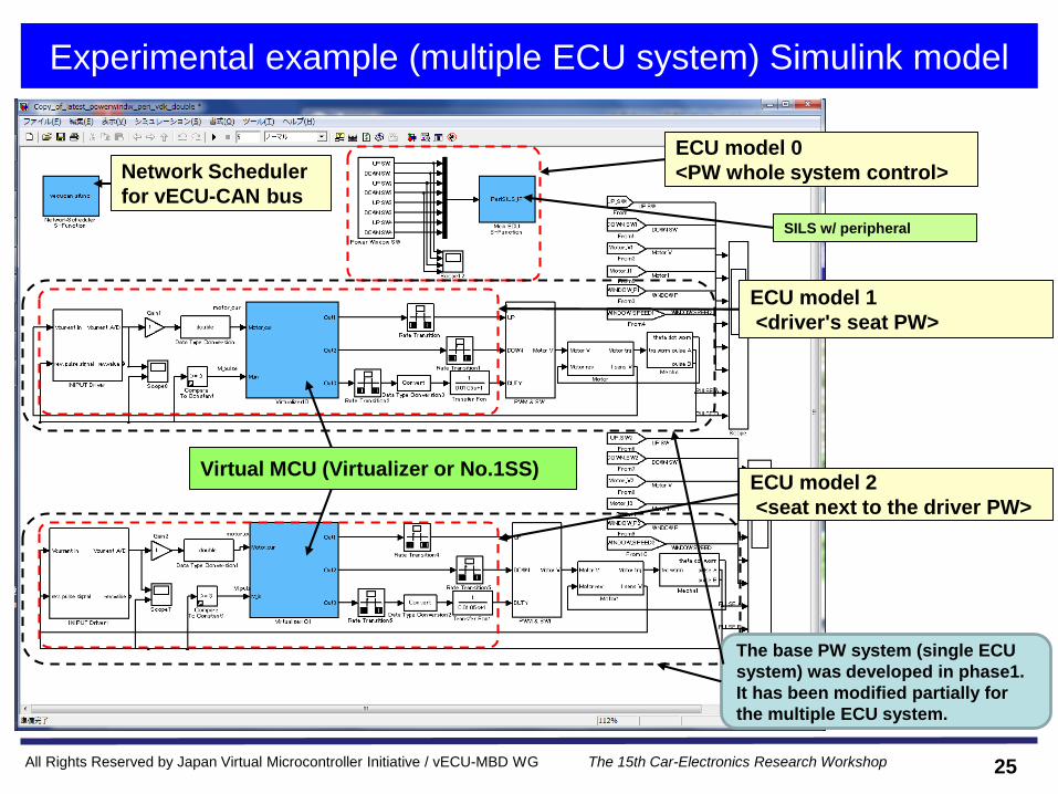
Experimental example (multiple ECU system) Simulink model
25
Network Scheduler
for vECU-CAN bus
ECU model 0
<PW whole system control>
SILS w/ peripheral
ECU model 1
<driver's seat PW>
The base PW system (single ECU
system) was developed in phase1.
It has been modified partially for
the multiple ECU system.
ECU model 2
<seat next to the driver PW>
Virtual MCU (Virtualizer or No.1SS)
All Rights Reserved by Japan Virtual Microcontroller Initiative / vECU-MBD WG The 15th Car-Electronics Research Workshop
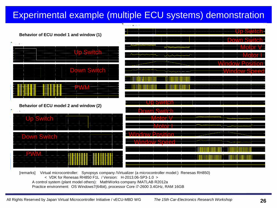
Experimental example (multiple ECU systems) demonstration
26
Up Switch
Down Switch
PWM
Up Switch
Down Switch
Window Position
Window Speed
Motor V
Motor I
Behavior of ECU model 2 and window (2)
Behavior of ECU model 1 and window (1)
Up Switch
Down Switch
PWM
Up Switch
Down Switch
Window Position
Window Speed
Motor V
Motor I
[remarks] Virtual microcontroller: Synopsys company /Virtualizer (a microcontroller model:) Renesas RH850)
< VDK for Renesas RH850 F1L / Version: H-2013.06-SP3-1.0 >
A control system (plant model others): MathWorks company /MATLAB R2012a
Practice environment: OS Windows7(64bit), processor Core i7-2600 3.4GHz, RAM 16GB
All Rights Reserved by Japan Virtual Microcontroller Initiative / vECU-MBD WG The 15th Car-Electronics Research Workshop
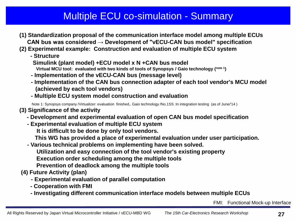
Multiple ECU co-simulation - Summary
(1) Standardization proposal of the communication interface model among multiple ECUs
CAN bus was considered → Development of "vECU-CAN bus model" specification
(2) Experimental example: Construction and evaluation of multiple ECU system
- Structure
Simulink (plant model) +ECU model x N +CAN bus model Virtual MCU tool: evaluated with two kinds of tools of Synopsys / Gaio technology (note 1)
- Implementation of the vECU-CAN bus (message level)
- Implementation of the CAN bus connection adapter of each tool vendor's MCU model
(achieved by each tool vendors)
- Multiple ECU system model construction and evaluation
Note 1: Synopsys company /Virtualizer: evaluation finished,. Gaio technology /No.1SS :In integration testing (as of June/'14 )
(3) Significance of the activity
- Development and experimental evaluation of open CAN bus model specification
- Experimental evaluation of multiple ECU system
It is difficult to be done by only tool vendors.
This WG has provided a place of experimental evaluation under user participation.
- Various technical problems on implementing have been solved.
Utilization and easy connection of the tool vendor's existing property
Execution order scheduling among the multiple tools
Prevention of deadlock among the multiple tools
(4) Future Activity (plan)
- Experimental evaluation of parallel computation
- Cooperation with FMI
- Investigating different communication interface models between multiple ECUs
FMI: Functional Mock-up Interface
27
All Rights Reserved by Japan Virtual Microcontroller Initiative / vECU-MBD WG The 15th Car-Electronics Research Workshop
3. Activity example introduction (2): Fault injection
4. Conclusion
1. Establishment background and activity summary of vECU-MBD
working group
2. Activity example introduction (1): Multiple ECU co-simulation
28
- Background
- Issues
- Requirements for standardization
- Application case
- Effectiveness
- Summary
All Rights Reserved by Japan Virtual Microcontroller Initiative / vECU-MBD WG The 15th Car-Electronics Research Workshop
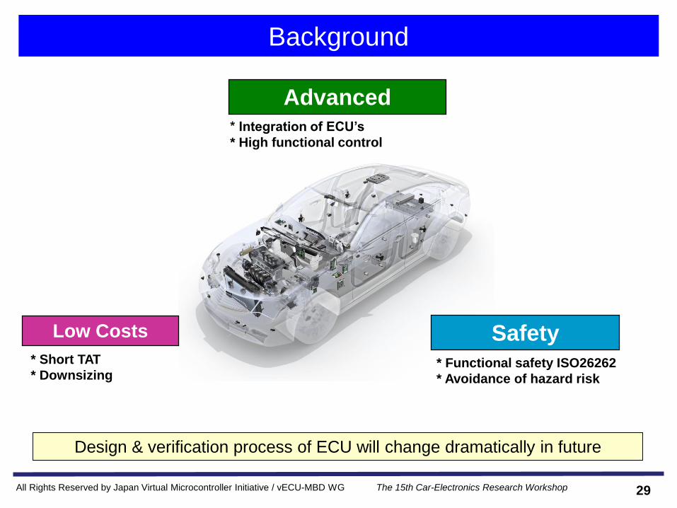
Background
Design & verification process of ECU will change dramatically in future
Advanced* Integration of ECU’s
* High functional control
Low Costs
* Short TAT
* Downsizing* Functional safety ISO26262
* Avoidance of hazard risk
Safety
29
All Rights Reserved by Japan Virtual Microcontroller Initiative / vECU-MBD WG The 15th Car-Electronics Research Workshop
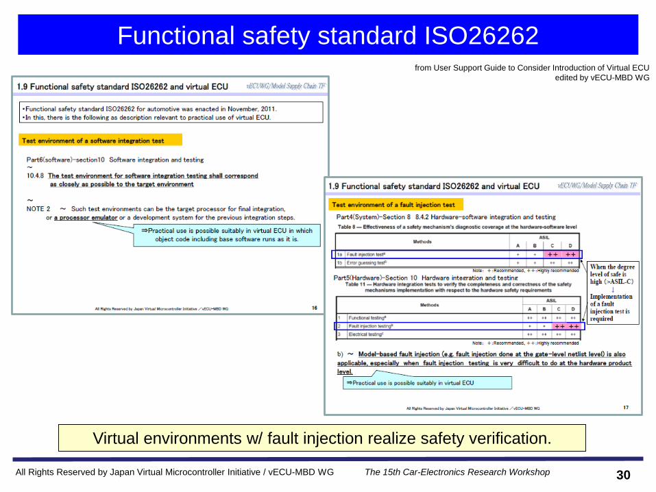
Functional safety standard ISO26262
Virtual environments w/ fault injection realize safety verification.
from User Support Guide to Consider Introduction of Virtual ECU
edited by vECU-MBD WG
30
All Rights Reserved by Japan Virtual Microcontroller Initiative / vECU-MBD WG The 15th Car-Electronics Research Workshop
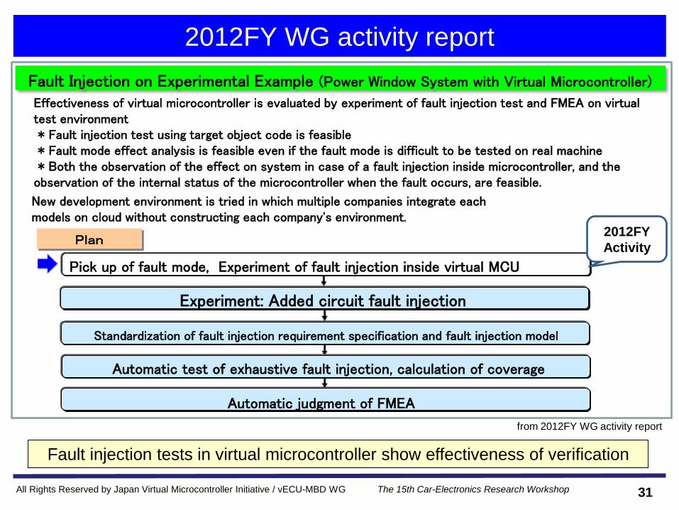
2012FY WG activity report
Fault injection tests in virtual microcontroller show effectiveness of verification
2012FY
Activity
Experiment: Added circuit fault injection
Standardization of fault injection requirement specification and fault injection model
Pick up of fault mode, Experiment of fault injection inside virtual MCU
Automatic test of exhaustive fault injection, calculation of coverage
Automatic judgment of FMEA
Effectiveness of virtual microcontroller is evaluated by experiment of fault injection test and FMEA on virtual test environment* Fault injection test using target object code is feasible* Fault mode effect analysis is feasible even if the fault mode is difficult to be tested on real machine* Both the observation of the effect on system in case of a fault injection inside microcontroller, and the
observation of the internal status of the microcontroller when the fault occurs, are feasible.
New development environment is tried in which multiple companies integrate each models on cloud without constructing each company's environment.
Fault Injection on Experimental Example (Power Window System with Virtual Microcontroller)
Plan
from 2012FY WG activity report
31

All Rights Reserved by Japan Virtual Microcontroller Initiative / vECU-MBD WG The 15th Car-Electronics Research Workshop
Difficulties for actual environment
Fault injection test for actual product
1. Fault injection flexibility: Fault point, timing, etc.
2. Waveform observation: Any point w/ destructive measurement
3. Short TAT: Long verification time w/ actual device
ECUSwitch
BOX
Vehicles
model
HILS
Verification methods: short circuit & wiring disconnection of ECU
ECU Unit
ECU Eva. board
IC
-> limitation of reproducible methodologies
Actual product verification environments
Virtual environment systems can lead to high test coverage
for complex safety requirements.
32

All Rights Reserved by Japan Virtual Microcontroller Initiative / vECU-MBD WG The 15th Car-Electronics Research Workshop
Issue analysis for virtual environment
Applic
ation
The bottlenecks are fault injection methodologies & modeling
1. Possibility fault injection: Any point & any timing
2. Early detection & short verification time w/o actual
product
3. Verification available w/o destructive measurement
■ Advantage
Case 1
Engine ECU motif:
Drive IC trouble
Case 2
FlexRay motif:
ECU clock trouble
Case 3
Case : A power window
Fault injection in RAM at microcontroller
1. Fault injection Mode / Point
2. Fault injection model design
3. Number of test results become enormous
-> Man-hours for judgment increase
■ Issues of the virtual system
Virtual environment
Virtual ECU
System levelLAN
ECU ECU ECU
Plant
Model
Virtual ECU simulator
McUModel
Circuit Model
Application
Software
Circuit Model
ECU + Plant
Modeling on PC
33
All Rights Reserved by Japan Virtual Microcontroller Initiative / vECU-MBD WG The 15th Car-Electronics Research Workshop
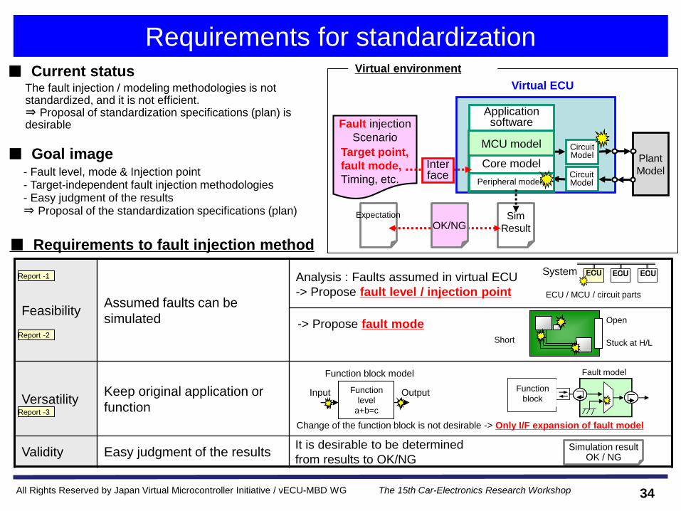
Requirements for standardizationVirtual environment
■ Requirements to fault injection method
- Fault level, mode & Injection point- Target-independent fault injection methodologies- Easy judgment of the results⇒ Proposal of the standardization specifications (plan)
■ Goal image
Virtual ECU
Plant
Model
Circuit Model
Circuit Model
MCU model
Core model
Application software
Peripheral models
Fault injection
Scenario
Target point,
fault mode,
Timing, etc.
Interface
Expectation Sim
ResultOK/NG
FeasibilityAssumed faults can be
simulated
VersatilityKeep original application or
function
Validity Easy judgment of the results
Short
Open
Stuck at H/L
Change of the function block is not desirable -> Only I/F expansion of fault model
機能ブロック
フォールトモデル
Report -1
Simulation result OK / NG
It is desirable to be determined
from results to OK/NG
System ECU ECU ECU
ECU / MCU / circuit parts
The fault injection / modeling methodologies is not standardized, and it is not efficient. ⇒ Proposal of standardization specifications (plan) is desirable
■ Current status
Input OutputFunction
level
a+b=c
Function block model
Function
block
Fault model
Report -2
Report -3
Analysis : Faults assumed in virtual ECU
-> Propose fault level / injection point
-> Propose fault mode
34

All Rights Reserved by Japan Virtual Microcontroller Initiative / vECU-MBD WG The 15th Car-Electronics Research Workshop
Standardization
• Fault level & injection point
• Fault mode
• Fault injection methodologies
• Judgment methodologies
35

All Rights Reserved by Japan Virtual Microcontroller Initiative / vECU-MBD WG The 15th Car-Electronics Research Workshop
Report 1: Fault level / Injection point
Proposal : The fault level & Injection point for the feasibility
Chip level ECU / MCU / ASIC level System level
Stuck low
Stuck high
Drift
Oscillation, etc.
Power & clock off
Incorrect R/W at ROM/RAM
Incorrect Output from I/O
Miss interrupt timing etc.
Parity error
Frame error
Overflow
Timing error, etc.
■ Fault level
■ Injection point System levelLAN
ECU ECU ECU
Virtual ECU
Plant
Model
Circuit Model
Circuit Model
MCU model
Core model
Application software
Peripheral models
Hardware Pin of MCU & ASIC
Pin of Electronic parts on ECU
(Resistor, Capacitor, Transistor, etc.)
ROM/RAM/Register in MCU & ASIC
Communication
network
Inter communication (UART etc.)
Outer communication (CAN, LIN etc.)
36
All Rights Reserved by Japan Virtual Microcontroller Initiative / vECU-MBD WG The 15th Car-Electronics Research Workshop
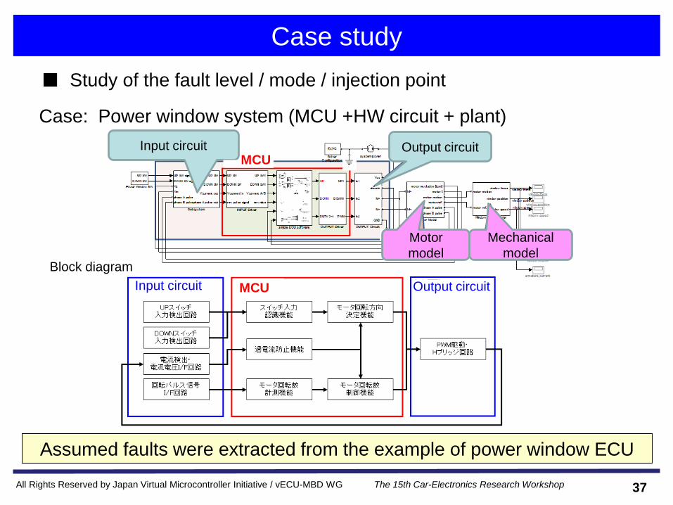
Case study
Case: Power window system (MCU +HW circuit + plant)
Assumed faults were extracted from the example of power window ECU
Block diagram
■ Study of the fault level / mode / injection point
Input circuit Output circuitMCU
MCUInput circuit Output circuit
Motor
model
Mechanical
model
37

All Rights Reserved by Japan Virtual Microcontroller Initiative / vECU-MBD WG The 15th Car-Electronics Research Workshop
Report 2: Fault mode
Block The fault which is derived Cause Cause / mechanism Mode
Input detect circuit Wrong detection / miss detection(pulse signals, etc.)
Pull-down resistor is short-circuit and stuck at Lo Stuck at Hi/Lo by the short-circuit of the part
1 stuck at Hi/Lo
Pull-up resistor of an open collector is open Open-circuit of the part
Function to prevent overcurrent
Abnormal input data from the sensor(Repetition of L ⇔ H)
A/D port of the MCU is shorten to P-RUN port Short-circuit between the adjacent terminals
2 bridge
Input detect circuit Wrong detection / miss detection Stuck at Lo due to malfunction of the port register Wrong data change in register 3 wrong data change
Input recognition function
Wrong output RAM wrong data Wrong data change
PWM drive circuit Abnormal input data from the sensor
Dynamic change of the sensor output Dynamic change (drift) 4 drift
Input recognition function
Slow reaction Delay of the interrupt in the MCU Delay 5 delay
Function to measure number of revolutions
Wrong detection Oscillation of the IC output Oscillation 6 oscillations
■ Category of the fault mode (Excerpt)
■ Fault modes have been selected according to the injection point
Hardware * Terminals of MCU, ASIC Stuck at Hi/Lo
Short-circuit between the adjacent terminals
* Terminals of electronic parts on ECU
(resistor, capacitor, transistor, etc.)
- Resistance: Open (and middle value fault)
- Capacitor: Open / short (and middle value fault)
- Transistor: Open of each terminal
Short-circuit between the adjacent terminals
* ROM/RAM/Register in MCU or ASIC Wrong data change of ROM/RAM/ register
Communication
network
* Internal communication (UART etc.)
* Outside communication (CAN, LIN etc.)
Wrong data change of frame data
Interrupt delay
Proposal : The six fault mode for the feasibility
38
All Rights Reserved by Japan Virtual Microcontroller Initiative / vECU-MBD WG The 15th Car-Electronics Research Workshop
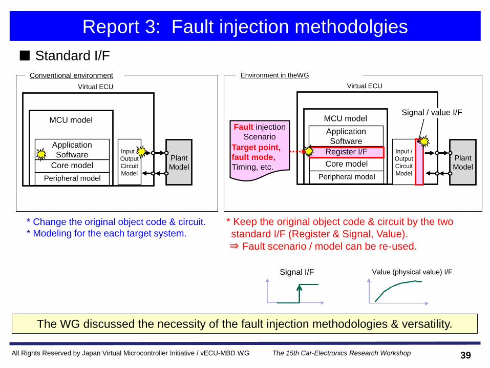
MCU model
Report 3: Fault injection methodolgies
■ Standard I/F
The WG discussed the necessity of the fault injection methodologies & versatility.
Fault injection
Scenario
Target point,
fault mode,
Timing, etc.
Virtual ECU
Plant
Model
Input /
Output
Circuit
Model
Core model
Application
Software
Peripheral model
Environment in theWG
Register I/F
Signal / value I/FMCU model
Virtual ECU
Plant
Model
Input /
Output
Circuit
Model
Core model
Application
Software
Peripheral model
* Change the original object code & circuit.
* Modeling for the each target system.
* Keep the original object code & circuit by the two
standard I/F (Register & Signal, Value).
⇒ Fault scenario / model can be re-used.
Signal I/F Value (physical value) I/F
Conventional environment
39

All Rights Reserved by Japan Virtual Microcontroller Initiative / vECU-MBD WG The 15th Car-Electronics Research Workshop
Application case
■ Contents
– Case1 : Failsafe verification of memory fault
• RAM data for number of motor revolutions is stuck at 0.
– Case2 : Failsafe verification of H/W circuit fault
• Resistor value of the switch input / output circuit is stuck at Lo.
40

All Rights Reserved by Japan Virtual Microcontroller Initiative / vECU-MBD WG The 15th Car-Electronics Research Workshop
Fail-safe verification of memory fault
■ Overview
Fault
scenario image
[Software specification]
Motor overcurrent : Over 3A
If the motor overcurrent continues 200ms, it is
determined abnormally, and a motor stops.
Fail-safe function verification of the
overcurrent detection to occur at the time of
MCU inside memory fault
Fail-safe function of memory fault has been verified.
MCU model
TIMER
ADCPORT
MEMCPU
MEM
Register I/F
CPU
Time Object Address Trouble level
■ Image of the fault injection
■ Verification
time[ms] Target Command address val
400 MEM Change 0x******** 0x0000
Injected fault: Change memory data
Command
Fault injection model
Fault injection model
Reading 0 fixation of the number of
revolutions
RAM
(number of
revolutions)CPU
RAM monitor (image)400[ms]
Simulation execution screen
Note: Normal behavior waveform
Window speed
Motor current
UP Switch Monitor
UP Switch Signal
Motor drive Current stop
Overcurrent detection
Window positionWindow top deadposition arrival
Window speed
Motor current
UP Switch Monitor
UP Switch Signal
Window position
Switch input signal
Switch input Comparison signal
200[ms]
injection model example
41
All Rights Reserved by Japan Virtual Microcontroller Initiative / vECU-MBD WG The 15th Car-Electronics Research Workshop
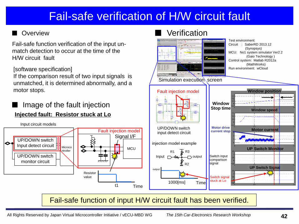
Fail-safe verification of H/W circuit fault
Input circuit models
Signal I/FUP/DOWN switch
Input detect circuit
■ VerificationTest environment:
Circuit : SaberRD 2013.12
(Synopsys)
MCU: No1 system simulator Ver2.2
(Gaio Technology )
Control system: Matlab R2012a
(MathWorks)
Run environment: wCloud
■ Overview
[software specification]
If the comparison result of two input signals is
unmatched, it is determined abnormally, and a
motor stops.
Fail-safe function verification of the input un-
match detection to occur at the time of the
H/W circuit fault
■ Image of the fault injection
Injected fault: Resistor stuck at Lo
Microco
ntroller
UP/DOWN switch
monitor circuit
MCU
Time
Resistor
value
t1
Window Stop time
Motor drive current stop
Window speed
Motor current
UP Switch Monitor
UP Switch Signal
Switch signal stuck at Lo
Switch input comparison signal
Fault injection model
Simulation execution screen
UP/DOWN switch input detect circuit
Fault injection model
injection model example
Input output
R3
R2
R1
Time
output
1000[ms]
Window position
Fail-safe function of input H/W circuit fault has been verified.
42

All Rights Reserved by Japan Virtual Microcontroller Initiative / vECU-MBD WG The 15th Car-Electronics Research Workshop
Effectiveness
MCU Resistor Capacitor Diode OP AMP CMOS logic MOS-FET
Up switch input detect circuit
Down switch input detect circuit1(2) 4(8) 2(4) - - - -
Current detection, current voltage I/F
circuit1(1) 6(12) 1(2) 4(8) 2(6) - -
Rotary pulse signal I/F circuit 1(1) 4(8) 2(4) - - - -
PWM drive, H bridge circuit 1(3) 5(10) - 4(8) - 11(33) 4(12)
Total 1(7) 19(38) 5(10) 8(16) 2(6) 11(33) 4(12)
number (number of the terminals)
■ Parts count in the whole systemTotal parts count in the power window system = 50 piecesExample:
- Single combination of fault injection point / modes
- For the analog parts, the middle value (drift) fault assumes six points as the following
Drift change : Four points of the standard value x2, x3, x(1/2), x(1/3)
Robustness : Two points of around threshold x1.1, x0.95, etc.
Approximately
500 test patterns
■ Virtual FMEA verification (partially extracted)
ASIL Object Part
name
Function Error Fault mode Effect degree Fatality
degree
Occurrence
frequency
Detection
degree
ASIL X Input detect
circuit
Resistor
-n
level
detection
Wrong
detection
stuck at H The window continues going
up without driver's will
* * *
stuck at L The window does not rise * * *
Expansion of the fault injection scenario and efficiency up of the verification
-> The effectiveness of the virtual FMEA verification
43

All Rights Reserved by Japan Virtual Microcontroller Initiative / vECU-MBD WG The 15th Car-Electronics Research Workshop
Fault injection - Summary
Motivation
Virtual fault injection standardization activity has been promoted
• Assumed faults have been extracted, and fault level / injection point / mode have
been proposed.
In addition, their concrete selection guide has been proposed
(WG’s user guide will be released)
• Fault injection methodolgies in consideration of versatility has been discussed.
• Application case of fail-safe verification w/o change of the target object code
⇒ Effectiveness of the virtual FMEA verification has been shown.
- ECU design & verification process will change due to environment change for complex function,
price reduction and safety
- Virtual ECU environment will be usable for correspondence to functional security standard ISO26262..
Future activity - Automatic test of exhaustive fault injection
- Automatic calculation of coverage
44
All Rights Reserved by Japan Virtual Microcontroller Initiative / vECU-MBD WG The 15th Car-Electronics Research Workshop
4. Conclusion
1. Establishment background and activity summary of vECU-MBD
working group
2. Activity example introduction (1): Multiple ECU co-simulation
3. Activity example introduction (2): Fault injection
45
All Rights Reserved by Japan Virtual Microcontroller Initiative / vECU-MBD WG The 15th Car-Electronics Research Workshop
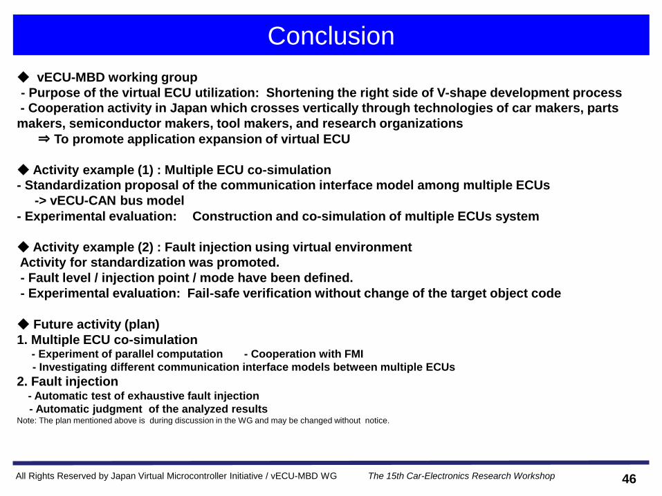
Conclusion
◆ vECU-MBD working group
- Purpose of the virtual ECU utilization: Shortening the right side of V-shape development process
- Cooperation activity in Japan which crosses vertically through technologies of car makers, parts
makers, semiconductor makers, tool makers, and research organizations
⇒ To promote application expansion of virtual ECU
◆ Activity example (1) : Multiple ECU co-simulation
- Standardization proposal of the communication interface model among multiple ECUs
-> vECU-CAN bus model
- Experimental evaluation: Construction and co-simulation of multiple ECUs system
◆ Activity example (2) : Fault injection using virtual environment
Activity for standardization was promoted.
- Fault level / injection point / mode have been defined.
- Experimental evaluation: Fail-safe verification without change of the target object code
◆ Future activity (plan)
1. Multiple ECU co-simulation- Experiment of parallel computation - Cooperation with FMI
- Investigating different communication interface models between multiple ECUs
2. Fault injection - Automatic test of exhaustive fault injection
- Automatic judgment of the analyzed resultsNote: The plan mentioned above is during discussion in the WG and may be changed without notice.
46

All Rights Reserved by Japan Virtual Microcontroller Initiative / vECU-MBD WG The 15th Car-Electronics Research Workshop
References
Japan Virtual Microcontroller Initiative / vECU-MBD WG exhibition document
http://www.vecu-mbd.org/
JMAAB exhibition document http://jmaab.mathworks.jp/
ISO26262 Road vehicles - Functional safety -
Shimada:Introduction of Joint Activity by JMAAB / Japan Virtual Microcontroller Initiative to
apply Virtual Microcontroller for Automotive Control System Simulation, The 11th Car-
Electronics Research Workshop, May 2012
Shimada, Yoshino, Saito: Trial of Model Based Development using Virtual ECU, ,The 13th
Car-Electronics Research Workshop, May 2013
Miyazaki: User guide development for using virtual ECU ~Introduction of vECU-MBD WG
Activity Example~, the 14th Car-Electronics Research Workshop, January, 2014
47

All Rights Reserved by Japan Virtual Microcontroller Initiative / vECU-MBD WG The 15th Car-Electronics Research Workshop
Thank you for your attention.
48