Embed Size (px)
Citation preview
THE 1962 VINTAGE TUNG SOL EI – 4 CAPACITIVE
DISCHARGE IGNITION FROM MOTION INC.
Dr. H. Holden, March. 2014.
INTRODUCTION:
The purpose of this article is to document this unusual piece of automotive electronics history in
such detail so as to allow it to be replicated by electronics engineers interested in Thyratron
based CDI units and to fully document the unit’s electronic design for future electronics
historians.
Without this effort the extraordinary technology of the EI-4 could be lost to the sands of time.
The EI-4 represents a prototype capacitive discharge ignition system which in its essence was the
basis for all commercial CDI units which followed, including those using SCR’s (Silicon
Controlled Rectifiers). In some respects the EI-4 was even more advanced than SCR units
appearing in the few years afterwards because it did not need a free running transistorized
DC:DC converter to operate, unlike the later SCR based units. On account of that it was far more
efficient consuming only 1 Amp of current per 1000 RPM in an 8 cylinder vehicle. It also used a
ferrite cored transformer ignition coil and had a number of other features.
Capacitive discharge ignition for automobiles had been experimented with in the 1950’s by the
Chrysler Corporation. However it was not until 1962 when Motion Inc of New Jersey in the
USA produced the EI-4 CDI unit based on the Tung Sol cold cathode Rectifier & cold cathode
Thyratron that a commercial unit or “add on CDI box” became readily available to the public.
The uptake was rapid and they were fitted to high performance racing and “muscle cars” such as
the Chevrolet Corvette. The name “Motion” gave the inspiration for the Baldwin-Motion
company name, that came later, but this was a different company specialising in the engineering
of racing Corvettes, however they used the EI-4 in a number of their performance cars.
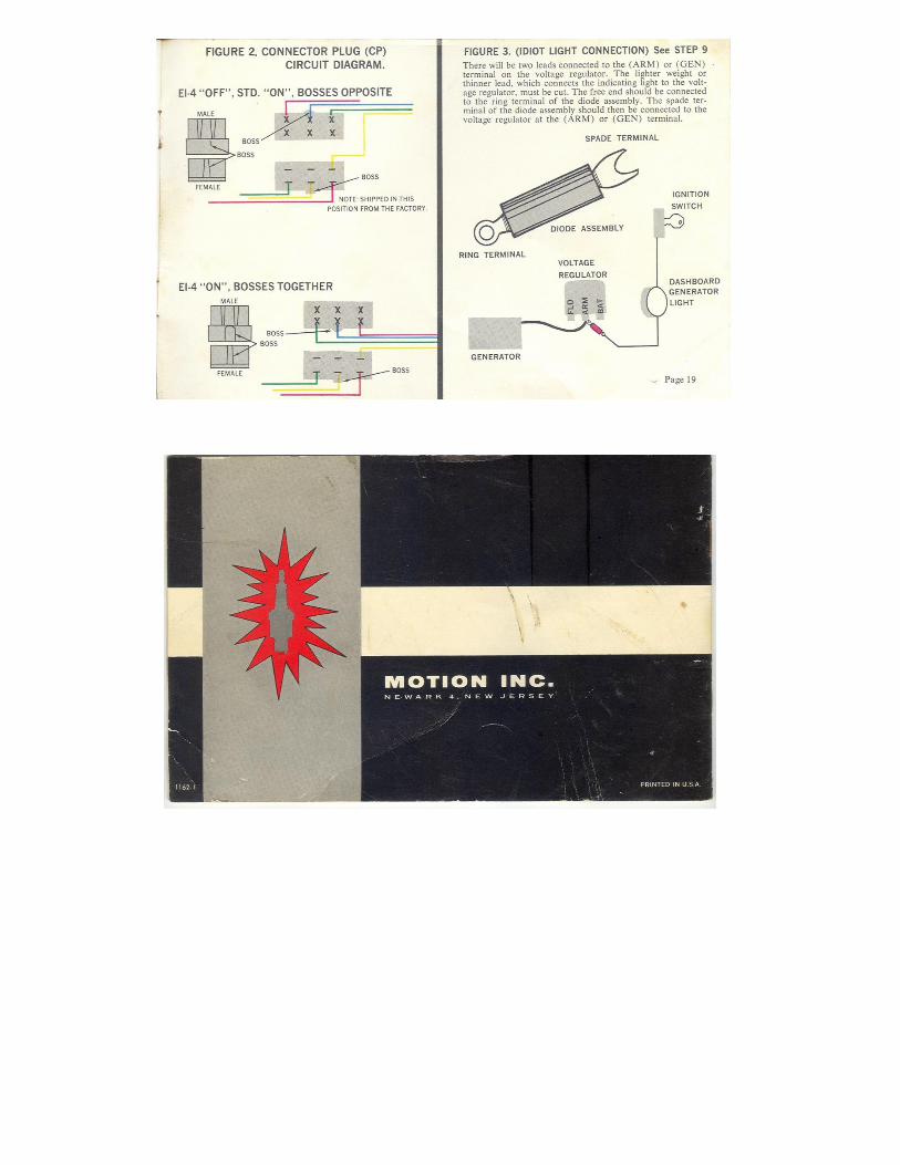
The EI-4 described in this article came in its original condition complete with the manufacturer’s
instruction manual and the special mating transformer type ignition coil. It had seen some use as
evidenced by heating of some of its internal components and wear on the handbook. The unit
was a positive earth version and was temporarily converted to negative earth to allow adequate
testing.
The EI-4 unit described here has been subject to a full laboratory analysis using test equipment
designed for spark energy analysis (see www.worldphaco.net “spark energy test machine”).

Also analysis of the circuit functionality is provided here along with detailed documentation of
the three especially designed transformers it contains and the ignition coil. The data recovered
includes the details of the transformer’s electrical properties, including total number of turns,
turns ratios, inductances, resistances and transformer core geometry and wire size where
available. The laboratory method by which this transformer data was acquired without having to
unwind or damage the transformers is explained in this article.
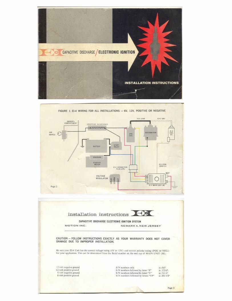
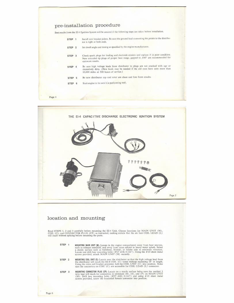
Prior to examining the actual EI-4 unit in detail, a copy is provided below of the manufacturer’s
handbook.
Note that the schematic shown on page 15 of the handbook is for the negative ground version.
In addition the polarities of the various transformer windings are not shown on the schematic.
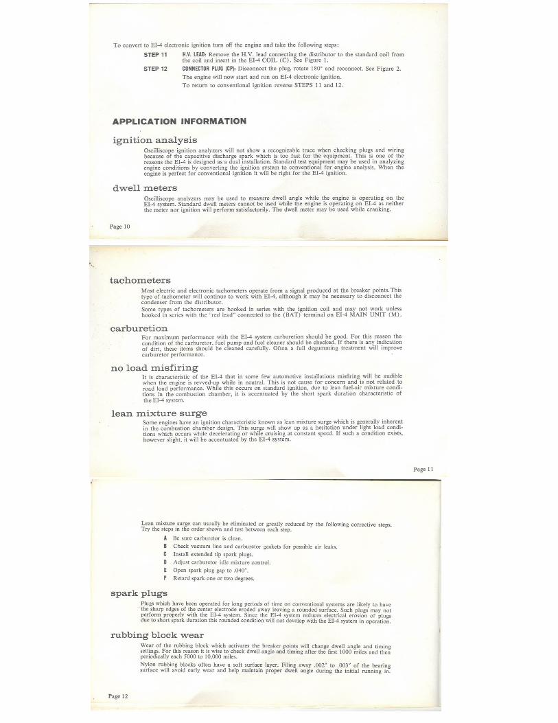
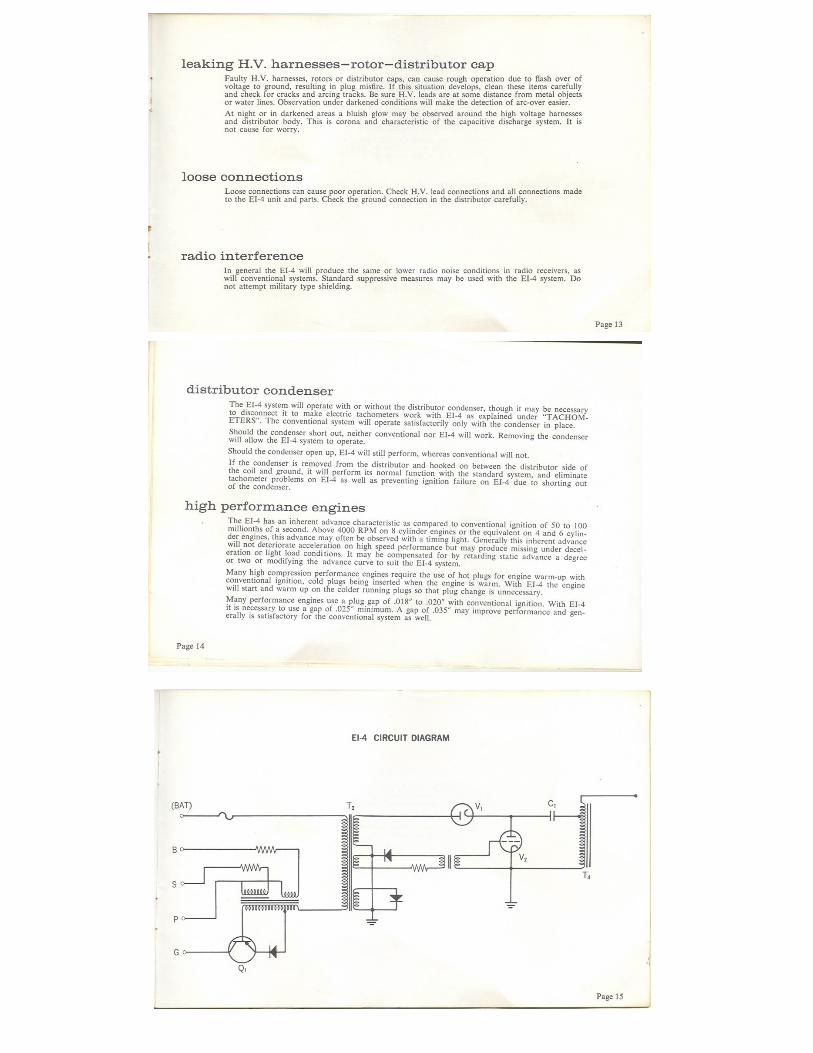
Another interesting point is that the description of how the unit operates, as given on page 16 of
the handbook under Theory “how it works” is not actually correct. For example the remark
about the breaker points closing and stopping the primary current of T2 is incorrect. In fact the
timing of the breaker points closing has no connection with the production of the spark generated
by the unit and only provides a re-magnetization function at some non critical and variable stage
during the operating cycle unless the rpm is so high that the contacts close less than 1.6mS after
they have opened. Tests indicate the EI-14 can support an 8 cylinder engine to about 6000 rpm.
The opening of the contacts is the important parameter. The contact breaker only needs to close
to re-magnetise T1’s (the input transformer) core for energy storage prior to the next cycle there
and this does not relate to any part of the timing cycle of the events generating the spark unless
the maximum rpm is exceeded and there insufficient time available to remagnetize T1. This is
explained in the analysis below in the sections on circuits & transformers & operating theory.
There is a typo on page 17, it says that the EI-4’s spark lasts 3 millionths of a second (3 micro
seconds), which is true and that an inductive spark lasts 150 millionths of a second (150uS or
0.15mS or milliseconds) which is not correct, it is usually about 1.5mS for an inductive
discharge spark.
Below is a copy of the manufacturer’s handbook:


CIRCUIT & TRANSFORMERS:
As shown above the handbook was fairly detailed. The section on Theory and the function of the
unit was glossed over and incorrect. However before going into a detailed circuit analysis and
oscilloscope waveforms, the designs of the transformers, including the ignition coil are shown
below.
The entire function of the EI-4 is very dependent on the design of its transformers. Every effort
has been made to document these as accurately as possible. The wire sizes were measured where
possible. The turns ratios & total number of turns were measured by threading some turns of
wire around the core and testing with applied AC voltages. (Note when doing this it is important
to apply a low impedance generator output voltage to the longest winding on the transformer or
transformer self resonances will corrupt the results).
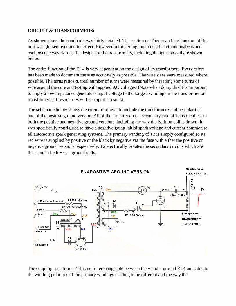
The schematic below shows the circuit re-drawn to include the transformer winding polarities
and of the positive ground version. All of the circuitry on the secondary side of T2 is identical in
both the positive and negative ground versions, including the way the ignition coil is drawn. It
was specifically configured to have a negative going initial spark voltage and current common to
all automotive spark generating systems. The primary winding of T2 is simply configured so its
red wire is supplied by positive or the black by negative via the fuse with either the positive or
negative ground versions respectively. T2 electrically isolates the secondary circuits which are
the same in both + or – ground units.
The coupling transformer T1 is not interchangeable between the + and – ground EI-4 units due to
the winding polarities of the primary windings needing to be different and the way the
transformer connections to the green wire of T2 were made common to the two primary
windings before exiting the transformer winding. This means that the winding connections to the
primary windings could not easily be reversed. So the two units EI-4 either + or – ground would
have used a different T1.
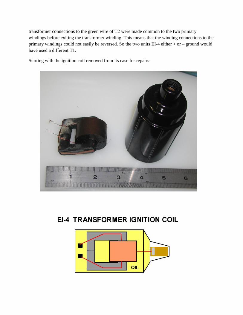
Starting with the ignition coil removed from its case for repairs:
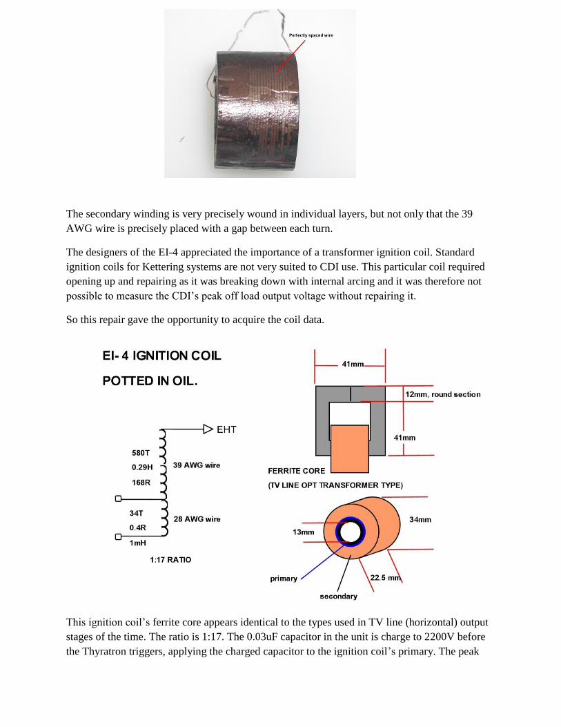
The secondary winding is very precisely wound in individual layers, but not only that the 39
AWG wire is precisely placed with a gap between each turn.
The designers of the EI-4 appreciated the importance of a transformer ignition coil. Standard
ignition coils for Kettering systems are not very suited to CDI use. This particular coil required
opening up and repairing as it was breaking down with internal arcing and it was therefore not
possible to measure the CDI’s peak off load output voltage without repairing it.
So this repair gave the opportunity to acquire the coil data.
This ignition coil’s ferrite core appears identical to the types used in TV line (horizontal) output
stages of the time. The ratio is 1:17. The 0.03uF capacitor in the unit is charge to 2200V before
the Thyratron triggers, applying the charged capacitor to the ignition coil’s primary. The peak
secondary voltage would therefore be expected to be around 39kV and have no difficulty
initiating spark ionization (see recordings later).
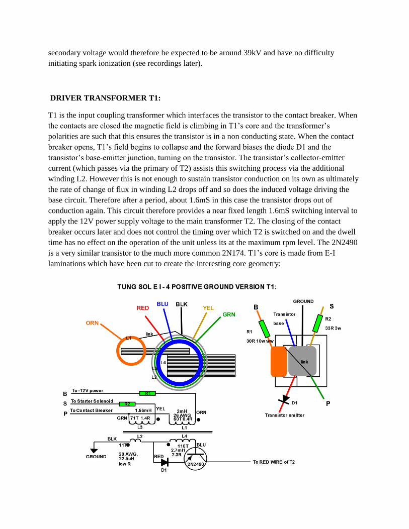
DRIVER TRANSFORMER T1:
T1 is the input coupling transformer which interfaces the transistor to the contact breaker. When
the contacts are closed the magnetic field is climbing in T1’s core and the transformer’s
polarities are such that this ensures the transistor is in a non conducting state. When the contact
breaker opens, T1’s field begins to collapse and the forward biases the diode D1 and the
transistor’s base-emitter junction, turning on the transistor. The transistor’s collector-emitter
current (which passes via the primary of T2) assists this switching process via the additional
winding L2. However this is not enough to sustain transistor conduction on its own as ultimately
the rate of change of flux in winding L2 drops off and so does the induced voltage driving the
base circuit. Therefore after a period, about 1.6mS in this case the transistor drops out of
conduction again. This circuit therefore provides a near fixed length 1.6mS switching interval to
apply the 12V power supply voltage to the main transformer T2. The closing of the contact
breaker occurs later and does not control the timing over which T2 is switched on and the dwell
time has no effect on the operation of the unit unless its at the maximum rpm level. The 2N2490
is a very similar transistor to the much more common 2N174. T1’s core is made from E-I
laminations which have been cut to create the interesting core geometry:
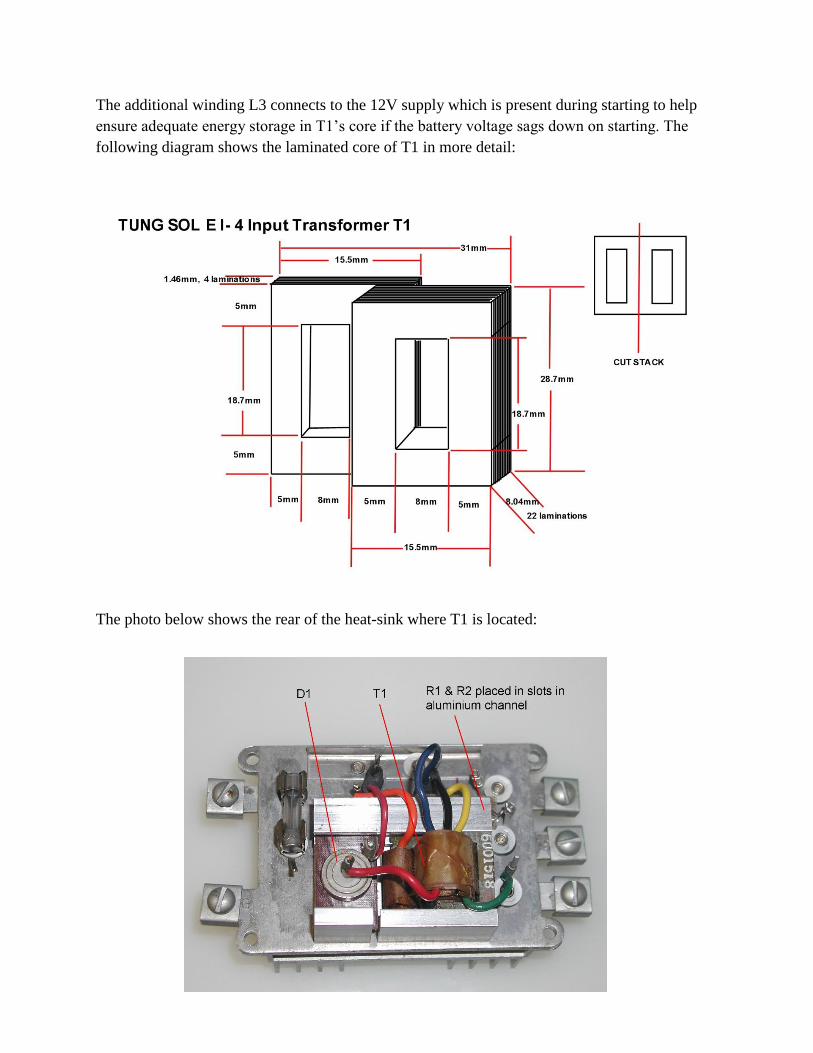
The additional winding L3 connects to the 12V supply which is present during starting to help
ensure adequate energy storage in T1’s core if the battery voltage sags down on starting. The
following diagram shows the laminated core of T1 in more detail:
The photo below shows the rear of the heat-sink where T1 is located:
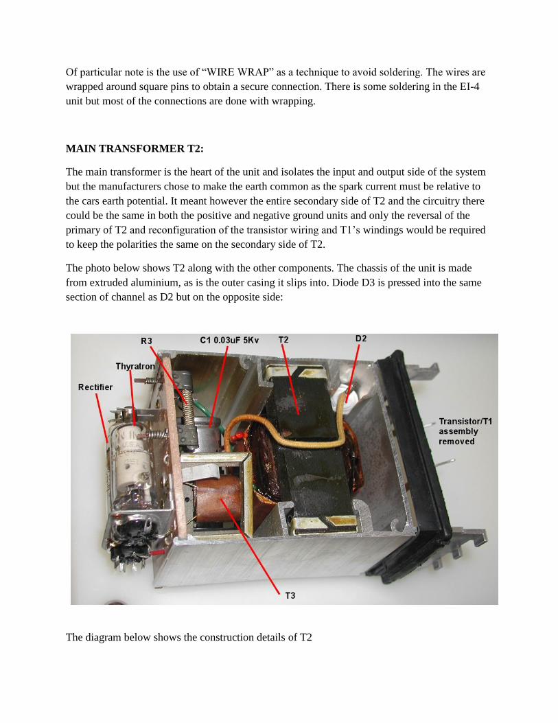
Of particular note is the use of “WIRE WRAP” as a technique to avoid soldering. The wires are
wrapped around square pins to obtain a secure connection. There is some soldering in the EI-4
unit but most of the connections are done with wrapping.
MAIN TRANSFORMER T2:
The main transformer is the heart of the unit and isolates the input and output side of the system
but the manufacturers chose to make the earth common as the spark current must be relative to
the cars earth potential. It meant however the entire secondary side of T2 and the circuitry there
could be the same in both the positive and negative ground units and only the reversal of the
primary of T2 and reconfiguration of the transistor wiring and T1’s windings would be required
to keep the polarities the same on the secondary side of T2.
The photo below shows T2 along with the other components. The chassis of the unit is made
from extruded aluminium, as is the outer casing it slips into. Diode D3 is pressed into the same
section of channel as D2 but on the opposite side:
The diagram below shows the construction details of T2
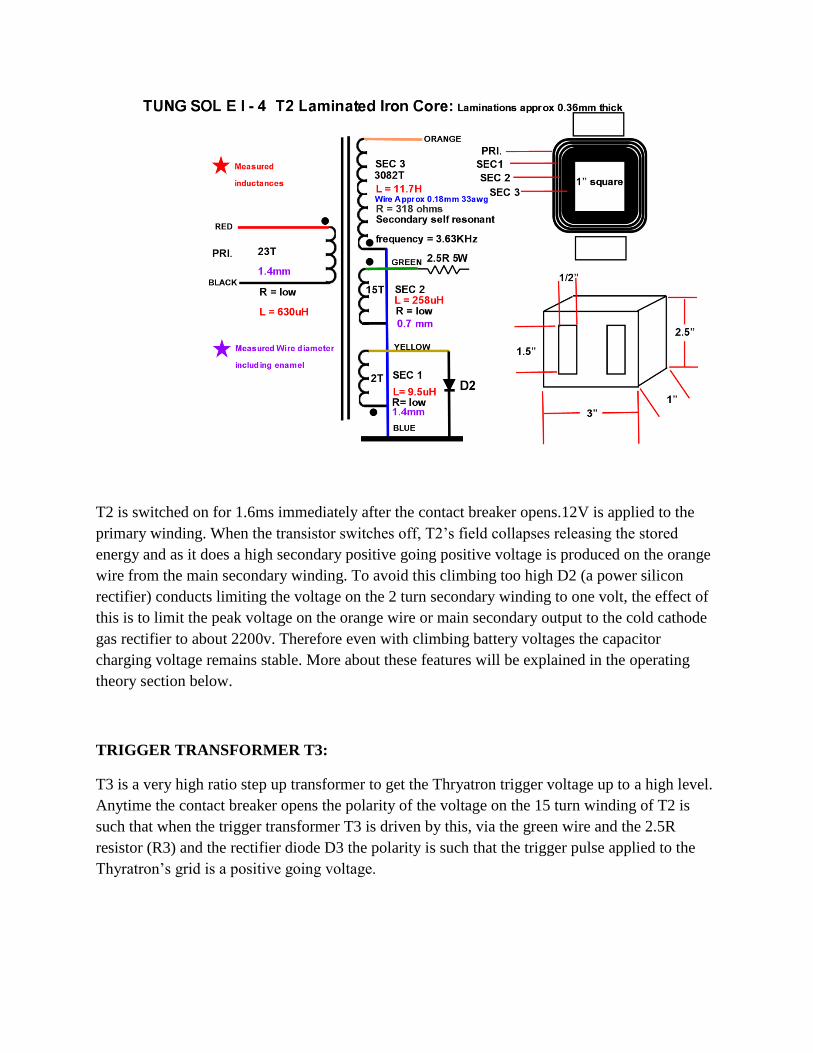
T2 is switched on for 1.6ms immediately after the contact breaker opens.12V is applied to the
primary winding. When the transistor switches off, T2’s field collapses releasing the stored
energy and as it does a high secondary positive going positive voltage is produced on the orange
wire from the main secondary winding. To avoid this climbing too high D2 (a power silicon
rectifier) conducts limiting the voltage on the 2 turn secondary winding to one volt, the effect of
this is to limit the peak voltage on the orange wire or main secondary output to the cold cathode
gas rectifier to about 2200v. Therefore even with climbing battery voltages the capacitor
charging voltage remains stable. More about these features will be explained in the operating
theory section below.
TRIGGER TRANSFORMER T3:
T3 is a very high ratio step up transformer to get the Thryatron trigger voltage up to a high level.
Anytime the contact breaker opens the polarity of the voltage on the 15 turn winding of T2 is
such that when the trigger transformer T3 is driven by this, via the green wire and the 2.5R
resistor (R3) and the rectifier diode D3 the polarity is such that the trigger pulse applied to the
Thyratron’s grid is a positive going voltage.
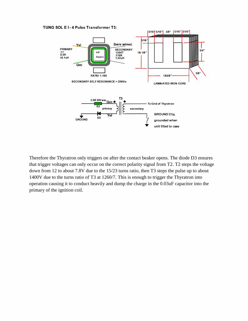
Therefore the Thyratron only triggers on after the contact beaker opens. The diode D3 ensures
that trigger voltages can only occur on the correct polarity signal from T2. T2 steps the voltage
down from 12 to about 7.8V due to the 15/23 turns ratio, then T3 steps the pulse up to about
1400V due to the turns ratio of T3 at 1260/7. This is enough to trigger the Thyratron into
operation causing it to conduct heavily and dump the charge in the 0.03uF capacitor into the
primary of the ignition coil.
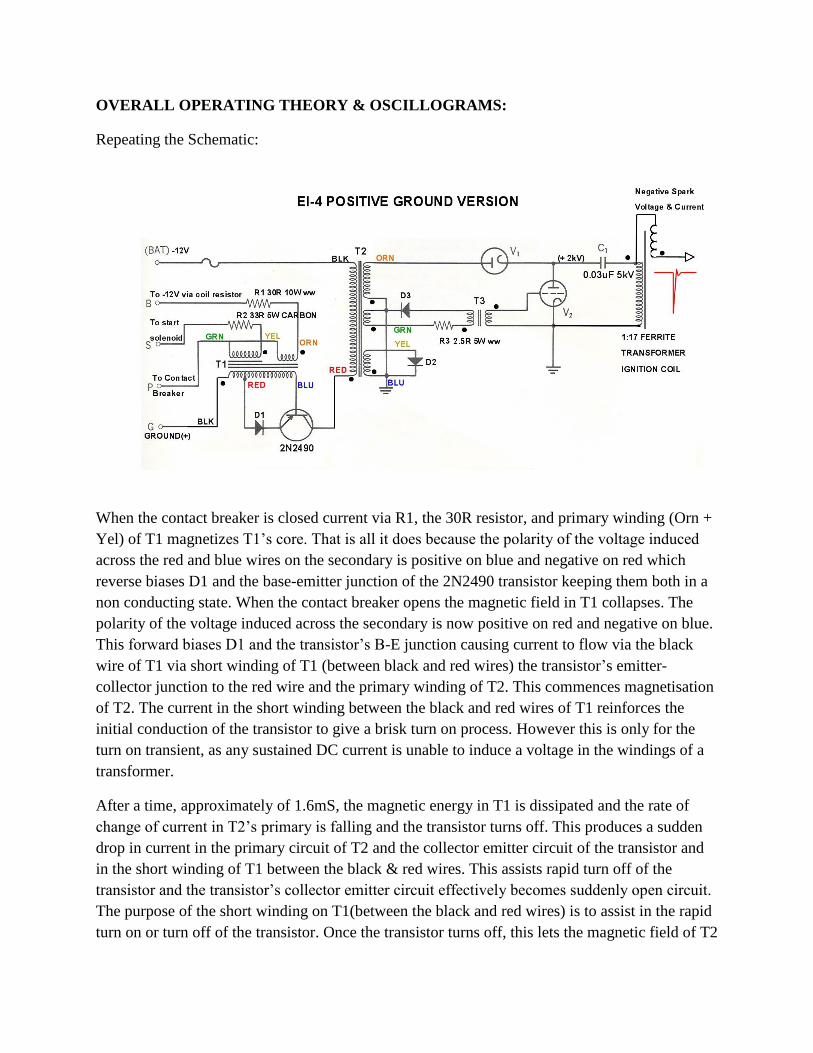
OVERALL OPERATING THEORY & OSCILLOGRAMS:
Repeating the Schematic:
When the contact breaker is closed current via R1, the 30R resistor, and primary winding (Orn +
Yel) of T1 magnetizes T1’s core. That is all it does because the polarity of the voltage induced
across the red and blue wires on the secondary is positive on blue and negative on red which
reverse biases D1 and the base-emitter junction of the 2N2490 transistor keeping them both in a
non conducting state. When the contact breaker opens the magnetic field in T1 collapses. The
polarity of the voltage induced across the secondary is now positive on red and negative on blue.
This forward biases D1 and the transistor’s B-E junction causing current to flow via the black
wire of T1 via short winding of T1 (between black and red wires) the transistor’s emitter-
collector junction to the red wire and the primary winding of T2. This commences magnetisation
of T2. The current in the short winding between the black and red wires of T1 reinforces the
initial conduction of the transistor to give a brisk turn on process. However this is only for the
turn on transient, as any sustained DC current is unable to induce a voltage in the windings of a
transformer.
After a time, approximately of 1.6mS, the magnetic energy in T1 is dissipated and the rate of
change of current in T2’s primary is falling and the transistor turns off. This produces a sudden
drop in current in the primary circuit of T2 and the collector emitter circuit of the transistor and
in the short winding of T1 between the black & red wires. This assists rapid turn off of the
transistor and the transistor’s collector emitter circuit effectively becomes suddenly open circuit.
The purpose of the short winding on T1(between the black and red wires) is to assist in the rapid
turn on or turn off of the transistor. Once the transistor turns off, this lets the magnetic field of T2
to collapse, only limited by the loads on T2’s other windings, because the primary winding is
completely unloaded. This produces a +2100 to +2200V peak voltage to appear on the secondary
(orange wire) of T2. This peak voltage causes the gas discharge rectifier V1 (which acts exactly
as a diode) to conduct, and the capacitor fully charges to 2000V with just one peak. It does not
require a series of pulses to fully charge the storage capacitor like a conventional CDI design
with the HAM radio style DC:DC converter (Royer Oscillator) which followed the EI-4 a few
years later.
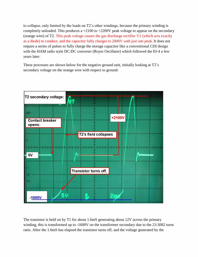
These processes are shown below for the negative ground unit, initially looking at T2’s
secondary voltage on the orange wire with respect to ground:
The transistor is held on by T1 for about 1.6mS generating about 12V across the primary
winding, this is transformed up to -1600V on the transformer secondary due to the 23:3082 turns
ratio. After the 1.6mS has elapsed the transistor turns off, and the voltage generated by the
collapsing field of T2 peaks to a stable 2100V to 2200V, due to the fact that the diode D2 across
the 2 turn secondary limits the peak voltage to 1V on that winding. Because the coupling
between the windings is not 100%, the voltage, rather than being limited to 1541V as predicted
by the 3082/2 turns ratio, in practice limits to about 2150V.
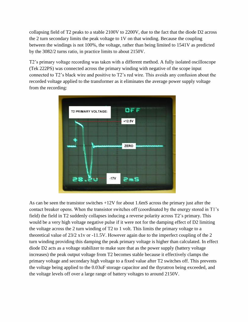
T2’s primary voltage recording was taken with a different method. A fully isolated oscilloscope
(Tek 222PS) was connected across the primary winding with negative of the scope input
connected to T2’s black wire and positive to T2’s red wire. This avoids any confusion about the
recorded voltage applied to the transformer as it eliminates the average power supply voltage
from the recording:
As can be seen the transistor switches +12V for about 1.6mS across the primary just after the
contact breaker opens. When the transistor switches off (coordinated by the energy stored in T1’s
field) the field in T2 suddenly collapses inducing a reverse polarity across T2’s primary. This
would be a very high voltage negative pulse if it were not for the damping effect of D2 limiting
the voltage across the 2 turn winding of T2 to 1 volt. This limits the primary voltage to a
theoretical value of 23/2 x1v or -11.5V. However again due to the imperfect coupling of the 2
turn winding providing this damping the peak primary voltage is higher than calculated. In effect
diode D2 acts as a voltage stabilizer to make sure that as the power supply (battery voltage
increases) the peak output voltage from T2 becomes stable because it effectively clamps the
primary voltage and secondary high voltage to a fixed value after T2 switches off. This prevents
the voltage being applied to the 0.03uF storage capacitor and the thyratron being exceeded, and
the voltage levels off over a large range of battery voltages to around 2150V.
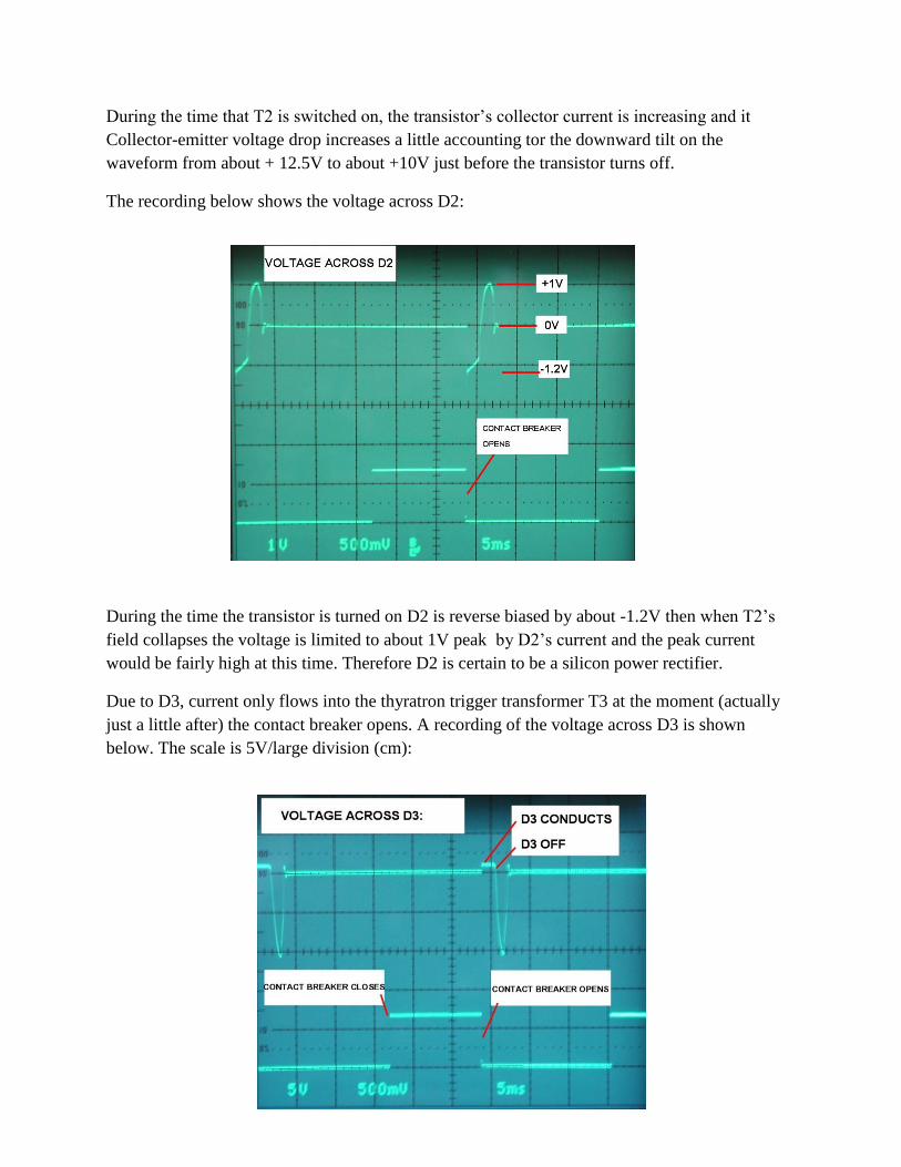
During the time that T2 is switched on, the transistor’s collector current is increasing and it
Collector-emitter voltage drop increases a little accounting tor the downward tilt on the
waveform from about + 12.5V to about +10V just before the transistor turns off.
The recording below shows the voltage across D2:
During the time the transistor is turned on D2 is reverse biased by about -1.2V then when T2’s
field collapses the voltage is limited to about 1V peak by D2’s current and the peak current
would be fairly high at this time. Therefore D2 is certain to be a silicon power rectifier.
Due to D3, current only flows into the thyratron trigger transformer T3 at the moment (actually
just a little after) the contact breaker opens. A recording of the voltage across D3 is shown
below. The scale is 5V/large division (cm):
D3’s forward voltage drop again is about 1V similar to D2 suggesting it is also a silicon
rectifier. As noted in the diagram above, the timing of the closure of the contact breaker is an
irrelevant feature of the operation of this CDI uni t (except perhaps at high RPM’s when time for
opening & closing is limited)
Another interesting and clever feature is that the trigger transformer T3, and the Thyratron, are
only driven into conduction during the time in which the voltage output from T2’s high voltage
winding is negative and the gas rectifier not conducting and the storage capacitor not charging.
This is completely unlike the situation in many CDI units where the discharge of the storage
capacitor loads the DC:DC converter at that time.
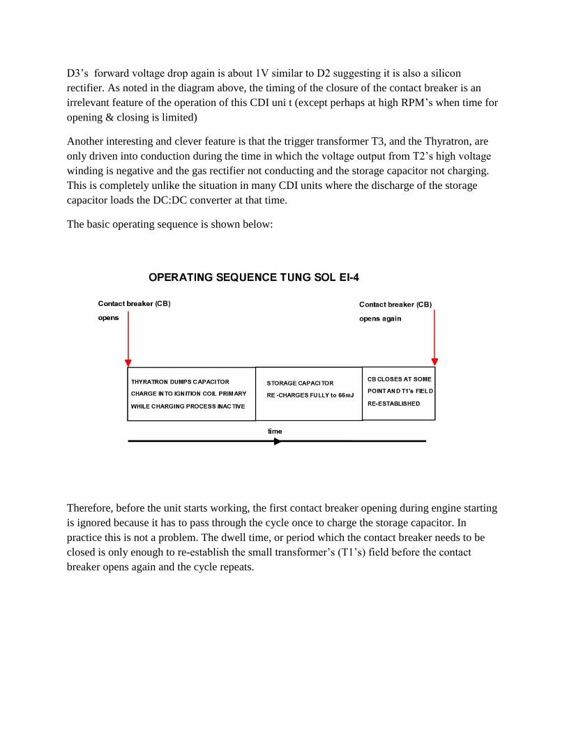
The basic operating sequence is shown below:
Therefore, before the unit starts working, the first contact breaker opening during engine starting
is ignored because it has to pass through the cycle once to charge the storage capacitor. In
practice this is not a problem. The dwell time, or period which the contact breaker needs to be
closed is only enough to re-establish the small transformer’s (T1’s) field before the contact
breaker opens again and the cycle repeats.
EI-4 SPARK VOLTAGE, SPARK CURRENT, SPARK ENERGY AND SPARK PULSE
POWER (SPP) & DISCUSSION OF THE EI-4 VS OTHER CDI SYSTEMS AND
INTRODUCING THE CONCEPT OF SPARK PULSE POWER or SPP:
The following measurements were performed on the EI-4 with the aid of the SPARK ENERGY
TEST MACHINE and a FREQUENCY COMPENSATED HIGH VOLTAGE PROBE and a Tek
2465b oscilloscope and its delay time-base functions. (see www.worldphaco.net for the details of
this apparatus)
SPARK BURN TIME (PHASE 2) SPARK CURRENT:
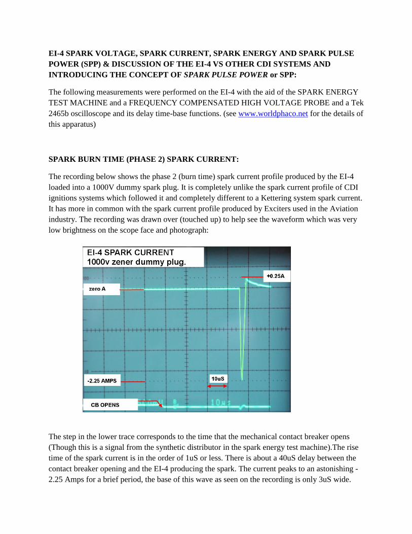
The recording below shows the phase 2 (burn time) spark current profile produced by the EI-4
loaded into a 1000V dummy spark plug. It is completely unlike the spark current profile of CDI
ignitions systems which followed it and completely different to a Kettering system spark current.
It has more in common with the spark current profile produced by Exciters used in the Aviation
industry. The recording was drawn over (touched up) to help see the waveform which was very
low brightness on the scope face and photograph:
The step in the lower trace corresponds to the time that the mechanical contact breaker opens
(Though this is a signal from the synthetic distributor in the spark energy test machine).The rise
time of the spark current is in the order of 1uS or less. There is about a 40uS delay between the
contact breaker opening and the EI-4 producing the spark. The current peaks to an astonishing -
2.25 Amps for a brief period, the base of this wave as seen on the recording is only 3uS wide.
Then there is a positive spark current of triangular shape peaking at about +0.2A and decaying
away over about 12uS. So this is a very brief spark compared to standard CDI’s which came
later, such as the Delta 10 unit, and very brief compared to Kettering spark currents which often
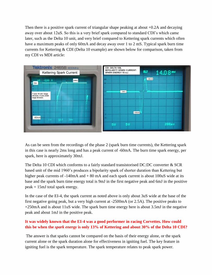
have a maximum peaks of only 60mA and decay away over 1 to 2 mS. Typical spark burn time
currents for Kettering & CDI (Delta 10 example) are shown below for comparison, taken from
my CDI vs MDI article:
As can be seen from the recordings of the phase 2 (spark burn time currents), the Kettering spark
in this case is nearly 2ms long and has a peak current of -60mA. The burn time spark energy, per
spark, here is approximately 30mJ.
The Delta 10 CDI which conforms to a fairly standard transistorised DC:DC converter & SCR
based unit of the mid 1960’s produces a bipolarity spark of shorter duration than Kettering but
higher peak currents of -140mA and + 80 mA and each spark current is about 100uS wide at its
base and the spark burn time energy total is 9mJ in the first negative peak and 6mJ in the positive
peak = 15mJ total spark energy.
In the case of the EI-4, the spark current as noted above is only about 3uS wide at the base of the
first negative going peak, but a very high current at -2500mA (or 2.5A). The positive peaks to
+250mA and is about 11uS wide. The spark burn time energy here is about 3.5mJ in the negative
peak and about 1mJ in the positive peak.
It was widely known that the EI-4 was a good performer in racing Corvettes. How could
this be when the spark energy is only 13% of Kettering and about 30% of the Delta 10 CDI?
The answer is that sparks cannot be compared on the basis of their energy alone, or the spark
current alone or the spark duration alone for effectiveness in igniting fuel. The key feature in
igniting fuel is the spark temperature. The spark temperature relates to peak spark power.
How to calculate peak spark power for a better comparison of three completely different
spark profiles:
Peak power is a measurement which is the product of peak voltage and peak current at some
instant when one or both values peak. Peak power therefore has units of V.A or Joules per
second. Peak spark power is proportional to the spark’s temperature or ionised gas temperature
and the higher the ionised gas temperature the better the surrounding gas ignition.
“Peak Powers” for the three types of sparks described above would be:
Kettering: 60mA x 1000V = 6 watts
Delta 10: 140mA x 1000 = 140 watts
EI-4 : 2500mA x 1000V = 2500 watts
Yet in the concept of “peak power” there is no actual time interval involved in an instantaneous
value. Any Physicist would agree that no physical process can take place in zero time (except
perhaps in a singularity where there is no time but a process, the Big Bang, did begin), or less
than one Planck interval if you like. Peak power numbers are in fact a “nonsense concept”
because units of power are Joules/second but the “instantaneous power” concept actually has no
time domain parameter.
Peak power numbers have been used in many industries for marketing purposes mainly,
involving audio and RF work to make the values seem large and impressive. For example
consider a 5 Volt rms sine wave applied to a 1 ohm resistor. The rms current is 5 Amps and there
is 25 Watts rms (heating) power. The peak current is 7.071 Amps and the peak voltage 7.071
Volts and the peak power value (number) is 50 watts to impress the reader with a bigger number
and make an amplifier for example seem more powerful than it really is.
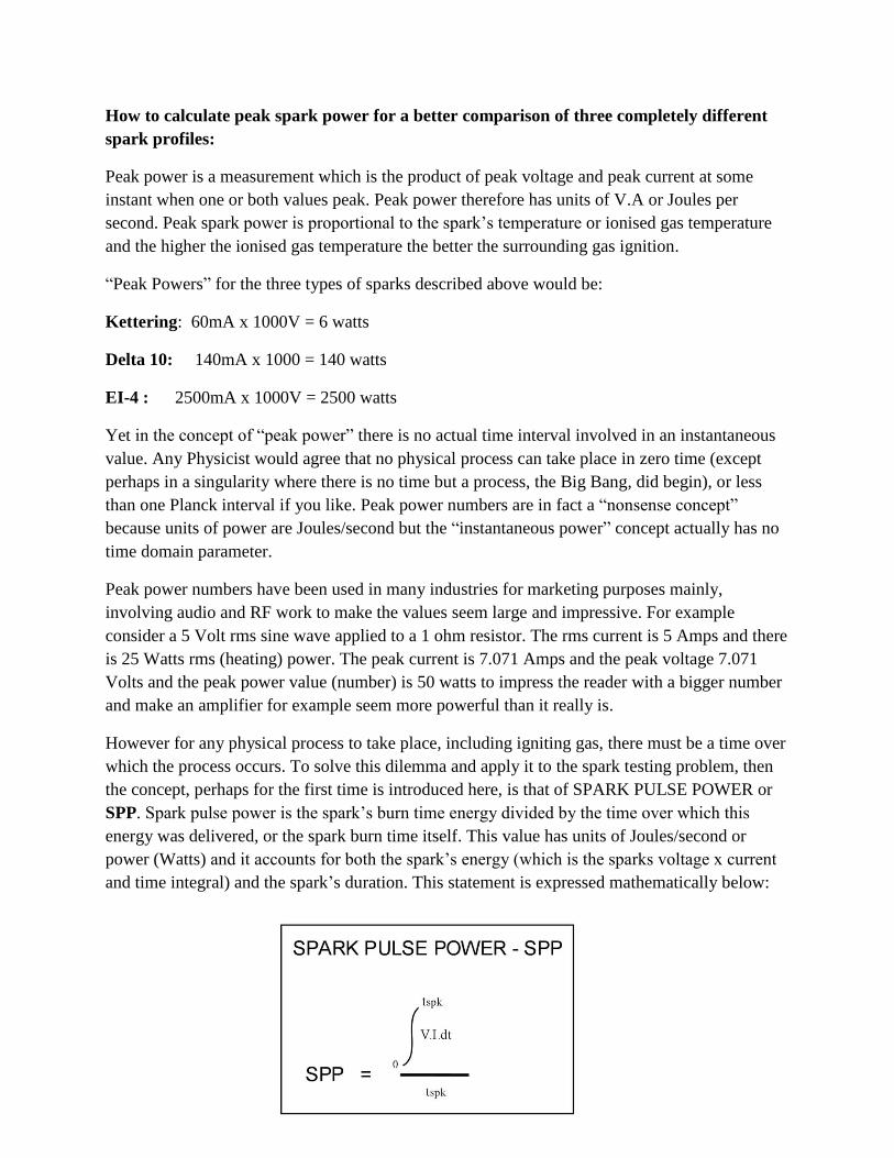
However for any physical process to take place, including igniting gas, there must be a time over
which the process occurs. To solve this dilemma and apply it to the spark testing problem, then
the concept, perhaps for the first time is introduced here, is that of SPARK PULSE POWER or
SPP. Spark pulse power is the spark’s burn time energy divided by the time over which this
energy was delivered, or the spark burn time itself. This value has units of Joules/second or
power (Watts) and it accounts for both the spark’s energy (which is the sparks voltage x current
and time integral) and the spark’s duration. This statement is expressed mathematically below:
So using SPP to compare the three sparks:
Kettering: 30mJ/2mS = 15 watts (only a negative peak)
Delta 10: 9mJ/100us = 90 watts (first negative peak)
EI-4: 3.5mJ/3uS = 1166 watts (first negative peak).
So it is likely the reason why the EI-4 was such a good performer in that it has a very high SPP,
which is much higher than Kettering or the Delta 10 CDI unit.
Apart form the fact that a gas thyratron has a limited life compared to a semiconductor, and
might have to be changed every 30,000 miles, this analysis suggests that the supposed design
improvements of the traditional CDI which followed the EI-4 in history were in some respects a
step backwards.
Another way to think about SPP is to imagine what happens to an object when a bolus of energy
is delivered to it. The spark itself is a physical object of sorts with the physical properties of a
gas and the electrical properties of a conductor like a metal. It can receive energy and heat up
or cool down by losing heat & other frequency spectrum electromagnetic radiation & light to its
surroundings. The easiest conceptual example to explain SPP is to think of another object like an
aluminium heat sink in equilibrium with the environment with a resistor thermally connected to it
and delivering heat to it. The heat sink properties are expressed by its thermal resistance or
degrees C temperature elevation above ambient temperature per Watt of applied power. The
spark too, as an object, will also have a thermal resistance. Therefore the temperature that the
heat sink rises to above ambient temperature depends on the applied power, or heat, in units of
Joules per second or watts. If the energy delivery is higher, eg a greater numbers of Joules per
second, the heat-sink (or spark plasma) will get hotter. Therefore, considering a single isolated
spark alone, with some number of Joules of energy, if it is delivered in a shorter time frame, this
will create a hotter spark, than the same amount of energy delivered over a longer time frame.
This is why SPP is an appropriate measure to compare spark temperature (and gas ignition
ability) than any other single parameter such as voltage, current or spark energy alone. SPP in
fact contains all this data plus the spark duration, so all the parameters are accounted for in one
measure.
Of course if a sequence of sparks is delivered, this also influences gas ignition ability because
the probability of ignition extends beyond that of a single spark.
The peak spark current is very high in the EI-4 and one might wonder if this could cause erosion
of the spark plug’s electrodes. It was stated in the manual above however that there is less spark
plug electrode wear with the EI-4 than the standard system, because the sparks are shorter (pg17
handbook).
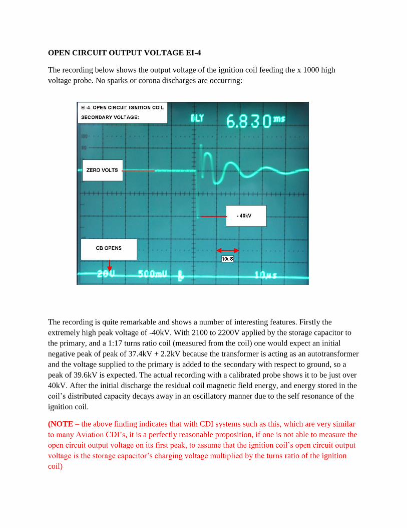
OPEN CIRCUIT OUTPUT VOLTAGE EI-4
The recording below shows the output voltage of the ignition coil feeding the x 1000 high
voltage probe. No sparks or corona discharges are occurring:
The recording is quite remarkable and shows a number of interesting features. Firstly the
extremely high peak voltage of -40kV. With 2100 to 2200V applied by the storage capacitor to
the primary, and a 1:17 turns ratio coil (measured from the coil) one would expect an initial
negative peak of peak of 37.4kV + 2.2kV because the transformer is acting as an autotransformer
and the voltage supplied to the primary is added to the secondary with respect to ground, so a
peak of 39.6kV is expected. The actual recording with a calibrated probe shows it to be just over
40kV. After the initial discharge the residual coil magnetic field energy, and energy stored in the
coil’s distributed capacity decays away in an oscillatory manner due to the self resonance of the
ignition coil.
(NOTE – the above finding indicates that with CDI systems such as this, which are very similar
to many Aviation CDI’s, it is a perfectly reasonable proposition, if one is not able to measure the
open circuit output voltage on its first peak, to assume that the ignition coil’s open circuit output
voltage is the storage capacitor’s charging voltage multiplied by the turns ratio of the ignition
coil)
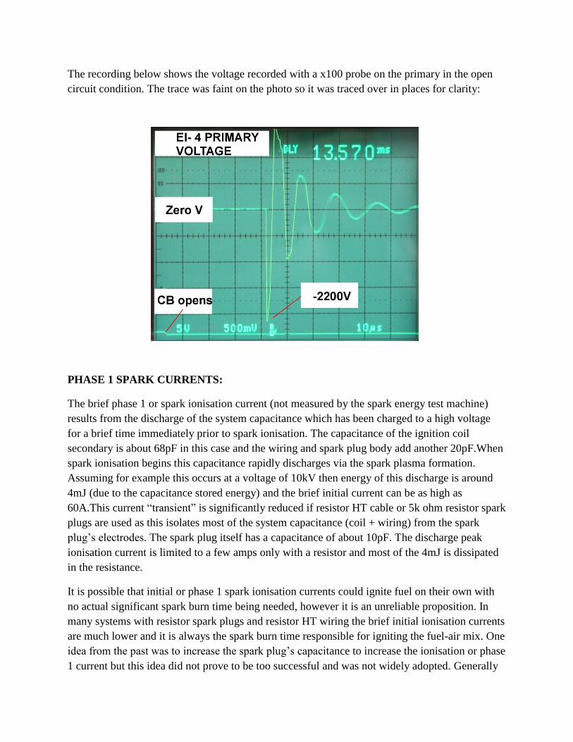
The recording below shows the voltage recorded with a x100 probe on the primary in the open
circuit condition. The trace was faint on the photo so it was traced over in places for clarity:
PHASE 1 SPARK CURRENTS:
The brief phase 1 or spark ionisation current (not measured by the spark energy test machine)
results from the discharge of the system capacitance which has been charged to a high voltage
for a brief time immediately prior to spark ionisation. The capacitance of the ignition coil
secondary is about 68pF in this case and the wiring and spark plug body add another 20pF.When
spark ionisation begins this capacitance rapidly discharges via the spark plasma formation.
Assuming for example this occurs at a voltage of 10kV then energy of this discharge is around
4mJ (due to the capacitance stored energy) and the brief initial current can be as high as
60A.This current “transient” is significantly reduced if resistor HT cable or 5k ohm resistor spark
plugs are used as this isolates most of the system capacitance (coil + wiring) from the spark
plug’s electrodes. The spark plug itself has a capacitance of about 10pF. The discharge peak
ionisation current is limited to a few amps only with a resistor and most of the 4mJ is dissipated
in the resistance.
It is possible that initial or phase 1 spark ionisation currents could ignite fuel on their own with
no actual significant spark burn time being needed, however it is an unreliable proposition. In
many systems with resistor spark plugs and resistor HT wiring the brief initial ionisation currents
are much lower and it is always the spark burn time responsible for igniting the fuel-air mix. One
idea from the past was to increase the spark plug’s capacitance to increase the ionisation or phase
1 current but this idea did not prove to be too successful and was not widely adopted. Generally
it is best to think of the phase 1 current as initiating the spark, while the burn time or phase 2
current creates the actual spark duration and is responsible for air-fuel ignition.
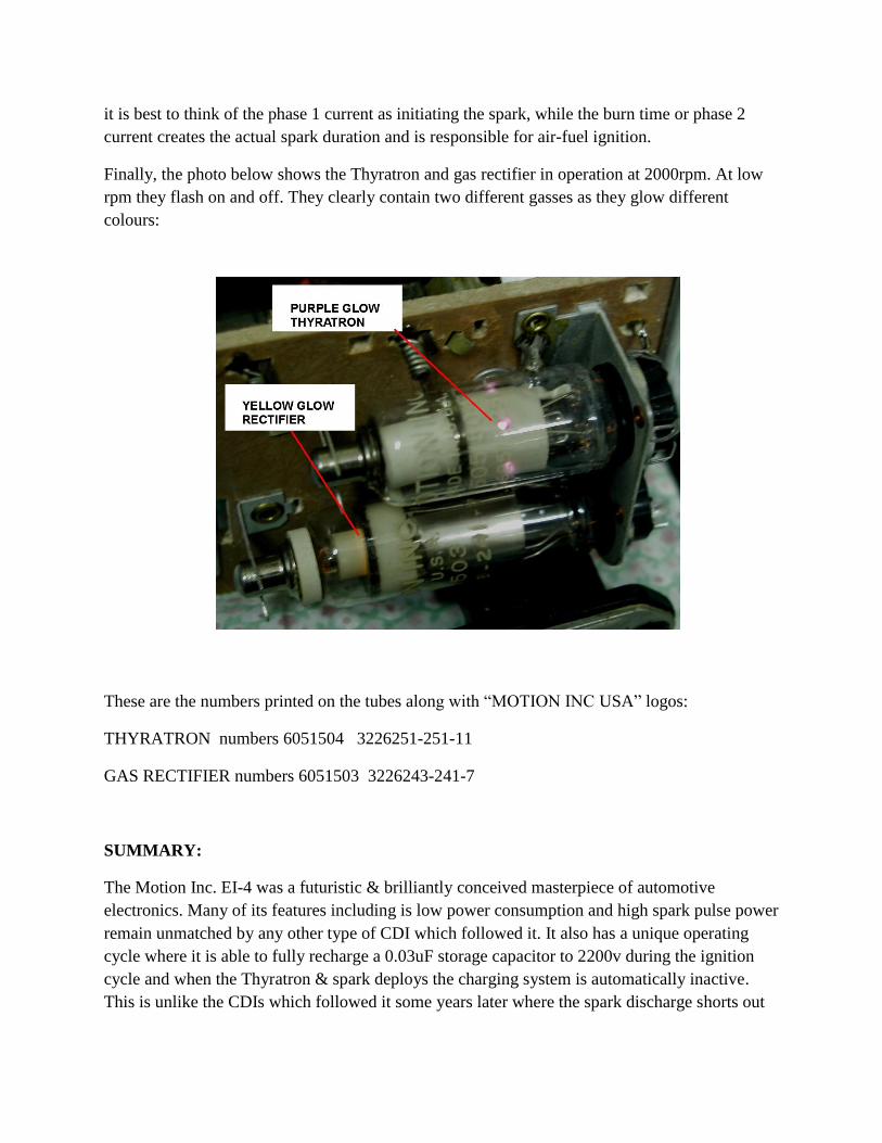
Finally, the photo below shows the Thyratron and gas rectifier in operation at 2000rpm. At low
rpm they flash on and off. They clearly contain two different gasses as they glow different
colours:
These are the numbers printed on the tubes along with “MOTION INC USA” logos:
THYRATRON numbers 6051504 3226251-251-11
GAS RECTIFIER numbers 6051503 3226243-241-7
SUMMARY:
The Motion Inc. EI-4 was a futuristic & brilliantly conceived masterpiece of automotive
electronics. Many of its features including is low power consumption and high spark pulse power
remain unmatched by any other type of CDI which followed it. It also has a unique operating
cycle where it is able to fully recharge a 0.03uF storage capacitor to 2200v during the ignition
cycle and when the Thyratron & spark deploys the charging system is automatically inactive.
This is unlike the CDIs which followed it some years later where the spark discharge shorts out
their DC:DC converters causing energy loss & converter recovery delays. Due to its design, the
EI-4’s power consumption is simply proportional to the RPM at 1A/1000 RPM.
The EI-4 has more in common with Aviation ignition exciters than any other device. In these
units the storage capacitors generally charge to around 2000V and are dumped into a ferrite
cored ignition coil by a gas discharge tube, which is not dissimilar to a gas cold cathode
thyratron except they do not have a trigger electrode.
The designers also had the wisdom to know that standard ignition coils used for Kettering
systems are not suitable for CDI use, so they designed a ferrite cored transformer coil to go with
the EI-4. They also had to go down that road anyway because their coil required a relatively low
turns ratio compared to a standard ignition coil. When CDI’s such as the Delta 10 were
introduced in the following years, the manufacturers clamed they did not need special ignition
coils and that Kettering coils were fine. This was for financial & marketing reasons, as a
transformer coil gives a significant (nearly twice as good) improvement over a standard coil with
CDI. Sales would have been lower if the buyer had to buy the CDI box plus a new ignition coil
as well.
I suspect that the technology in the EI-4 was simply overlooked by the developers of CDI units
which came in the years later. Or perhaps they kept away from it because of patents or
unfounded worries about the reliability of the Thyratron. Also the SCR’s of the time had more
limited voltage ratings than the Thyratron and wouldn’t lend themselves well to an EI-4 circuit.
Like many brilliant and clever designs, I think it was ill understood and not studied or
documented well enough by others. The basic schematic diagram in the handbook did not reveal
many of its secrets at all.
As explained above, the purpose of this paper is to document this unique piece of equipment for
future electronics historians and for those who like to design and build their own CDIs. It is
possible for example to use this design concept with a group of high voltage SCR’s to achieve a
similar design in a solid state format and thereby improve on existing CDI systems. Another
option is the newer range of trigger-able gas discharge tubes applied to this design and making
use of more modern transformer cores and high voltage silicon rectifiers such as those used in
aircraft exciters.
***********************************************************************************


![C1.10 Consumables Product Catalog - O.E. Meyer · PDF file[146] THE LINCOLN ELECTRIC COMPANY FLUX-CORED SUBMERGED ARC STAINLESS & NICKEL HARDFACING Selection Guide FLUX-CORED Flux-Cored](https://img.pdfslide.net/doc/110x75/5a7224fc7f8b9a93538d7cf9/c110-consumables-product-catalog-oe-meyer-nbsppdf-file146-the.jpg)