Embed Size (px)
Citation preview

133electronics and electromagnetics 2005 NRL Review
The Advanced Multifunction RF Concept (AMRFC) Test Bed
with functions broadly grouped: Communications, Electronic Warfare, Radar, and Calibration. Many functions within these groups have been selected for demonstration. Others that can be defi ned in terms of the apertures, hardware, and test bed software can be added later. Currently, Communications include line-of-sight using the Ku-band Tactical Common Data Link (TCDL) as well as satellite communica-tions, both commercial Ku-band and a military link at X-band. Within Electronic Warfare, Electronic Attack (EA) provides noise and deceptive jamming. Electronic Surveillance (ES) fulfi lls High Probability of Intercept (HPOI) and Precision Direction Finding (PDF). A surface navigation function is demonstrated within the Radar function. Array and subsystem calibration, functional characterization, and diagnos-tics—all critical to dynamic maintenance of test bed operation—are part of the Calibration group. Other shipboard functions can now be added by using the hardware and software developed in this program.
Th e cornerstone for this work is the fl exibility engendered by broadband dual-polarized phased array antennas that operate under the control of common system resource allocation manager (RAM) software. Together with a real-time control network, all the functions are defi ned. Figure 1 illustrates the receiver array partitioned (independently controlled parallel receive array channels, or ports, are shown separately
FIGURE 1AMRFC receive array and transmit array, illustrating selectable partitioning to support RF functions. Difference in angle orientation refl ect individual contractor’s approach.
G.C. TavikRadar DivisionI.D. OlinSFA Inc.
Introduction: A glance at any Navy fi ghting ship underscores the goal of the technology being developed and demonstrated in this multidivision, multilaboratory program, sponsored and inspired by the Offi ce of Naval Research. Today, single system antennas increasingly clutter our ships. Over just the ten-year 1980-1990 period, many ship classes that ini-tially had fewer than 100 antennas needed nearly 150. Mutual signal interference, ship’s signature, manning, spares, and life cycle costs all point to the need for a multifunctional concept in which systems are defi ned by their functions and by software that drives the electronics of a single antenna suite. In this program, hardware and software that emulate Emission Control, Normal, and Combat scenarios have been successfully combined in an active Proof of Principle demonstra-tion at NRL’s Chesapeake Bay Detachment (CBD).
System Flexibility Enables a Broad Spectrum of Functionality: Th e test bed operates over 6-18 GHz
134 2005 NRL Review electronics and electromagnetics
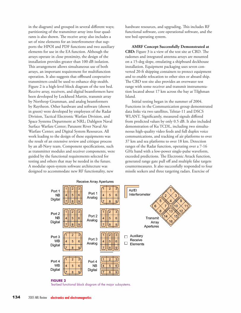
in the diagram) and grouped in several diff erent ways; partitioning of the transmitter array into four quad-rants is also shown. Th e receive array also includes a set of nine elements for an interferometer that sup-ports the HPOI and PDF functions and two auxiliary elements for use in the EA function. Although the arrays operate in close proximity, the design of the installation provides greater than 100 dB isolation. Th is arrangement allows simultaneous use of both arrays, an important requirement for multifunction operation. It also suggests that off board cooperative transmitters could be used to enhance ship stealth. Figure 2 is a high-level block diagram of the test bed. Receive array, receivers, and digital beamformers have been developed by Lockheed Martin, transmit array by Northrop Grumman, and analog beamformers by Raytheon. Other hardware and software (shown in green) were developed by employees of the Radar Division, Tactical Electronic Warfare Division, and Space Systems Department at NRL; Dahlgren Naval Surface Warfare Center; Patuxent River Naval Air Warfare Center; and Digital System Resources. All work leading to the design of these equipments was the result of an extensive review and critique process by an all-Navy team. Component specifi cations, such as transmitter modules and receiver components, were guided by the functional requirements selected for testing and others that may be needed in the future. A modular open-system software architecture was designed to accommodate new RF functionality, new
FIGURE 2Test-bed functional block diagram of the major subsystems.
hardware resources, and upgrading. Th is includes RF functional software, core operational software, and the test bed operating system.
AMRF Concept Successfully Demonstrated at CBD: Figure 3 is a view of the test site at CBD. Th e radomes and integrated antenna arrays are mounted on a 15-deg slope, emulating a shipboard deckhouse installation. Equipment packaging uses seven con-verted 20-ft shipping containers to protect equipment and to enable relocation to other sites or aboard ship. Th e CBD test site also provides an overwater test range with some receiver and transmit instrumenta-tion located about 17 km across the bay at Tilghman Island.
Initial testing began in the summer of 2004. Functions in the Communication group demonstrated data links via two satellites, Telstar-11 and DSCS WLANT. Signifi cantly, measured signals diff ered from predicted values by only 0.5 dB. It also included demonstration of Ku TCDL, including two simulta-neous high-quality video feeds and full duplex voice communications, and tracking of air platforms to over 37 km and sea platforms to over 18 km. Detection ranges of the Radar function, operating over a 7-16 GHz band with a low-power single-pulse waveform, exceeded predictions. Th e Electronic Attack function, generated range gate pull off and multiple false targets countermeasures. It also successfully responded to four missile seekers and three targeting radars. Exercise of

135electronics and electromagnetics 2005 NRL Review
the antenna polarization diversity, a part of this func-tion, was also successful. Th e Electronic Surveillance function successfully demonstrated digital channelized receivers for each of the array embedded elements. Emitters of opportunity, including those aboard a P-3 aircraft, an NRL boat, and Tilghmann Island naviga-tion radars, were successfully detected. Th e Calibration function is critical to the dynamic maintenance of the test bed operation. To date, it has provided initial function calibrations and implemented a transmit calibration mode.
Th e success of our contractor and Government team in fulfi lling the goals of this program and in the various aspects of the design, hardware, software, and testing emphasize the recurring theme that the AMRFC test bed is dealing with various functions, rather than systems. Th e former implies fl exibility; the latter refl ects increasing proliferation of special above and below decks equipments.
[Sponsored by ONR]
FIGURE 3AMRFC test-bed at NRL’s Chesapeake Bay Detachment Test facility.