Embed Size (px)
Citation preview
an International NDT ConferenceIrani rdProceedings of the 3IRNDT2016 Feb 21-22, 2016, Olympic Hotel, Tehran, Iran
IRNDT2016-T03118
The advantages of Phased Array Ultrasonic Testing (PAUT) & Time of flight Diffraction (TOFD) Combination instead of using individually on ASME U stamp Pressure vessel fabrication projects.
Hosein Taheri1, Hashem Rahmati2
1. Farin Sout Pishrafteh Engineering Co. Tehran, Iran, [email protected] 2. Pishrafteh NDT Co. Tehran, Iran, [email protected]
Abstract:
The Phased Array Ultrasonic Testing (PAUT) and Time of Flight Diffraction (TOFD) technologies have made rapid changes in inspection and reliability in various industries. Ultrasonic phased arrays are a new technology that offers considerable potential for inspecting construction welds. Using electronic control of the beam, phased arrays can scan, sweep, steer and focus the ultrasound. Since welds typically produce defects of known character and orientation, phased arrays can be programmed to optimize weld inspections. These inspections include standard ASME-type pulse echo raster scans, zone discrimination, TOFD and “specials”, depending on the vessel, weld profile, geometry and specifications. The Time-of-Flight Diffraction technique (TOFD) was originally developed as a method of accurately sizing and monitoring the through wall height of flaws in the industry. It is equally effective in weld inspection for the detection of flaws, irrespective of type or orientation, since TOFD does not rely on the reflectivity of the flaw but uses the diffracted sound initiating from the flaw tips. A major advantage of PAUT & TOFD methods combination is effective procedure for better sizing and location determination of the discontinuities.
This paper discusses the combination of PAUT & TOFD methods instead of individually for weld inspection on pressure vessel projects.
Keywords:
Phased array ultrasonic testing, TOFD, Sectorial scan, Beam intersection, combination of PAUT & TOFD
Introduction:
Prevention of disasters is a major concern in any industry. Nondestructive testing as a reliable tool has played an effective and
important role in this regard. Conventional Ultrasonic testing of heavy wall thickness pressure vessels is a common practice.
Due to the increasing demand for more thorough inspection of pressure vessels, researchers have begun looking into more
innovative means of defect measurement. Principally, the Phased Array Ultrasonic Testing (PAUT) & Time-Of-Flight
Diffraction (TOFD) flaw detection procedure has been implemented to achieve good results and this combination shown to be
an effective procedure for size and location determination of a discontinuities.
Specifically, this combination was proven that this is more suitable for thick structures (above 13mm). Today, the PAUT &
TOFD procedure is used for operational inspections or quality control of structures during production instead of routine
radiography and conventional ultrasonic shear wave procedures. Although TOFD is more often utilized for inspecting welds
with simple geometry and fine grain steels, such as welds with thicknesses from 13 mm to 300 mm, it is useful in inspecting
more complex geometries.
Defects like cracks, lack of penetration, Lack of fusion, porosity, and slag in welds of pressure vessels could be
diagnosed via this technique very precisely.
Mor
e In
fo a
t Ope
n A
cces
s D
atab
ase
ww
w.n
dt.n
et/?
id=
1914
3
an International NDT ConferenceIrani rdProceedings of the 3IRNDT2016 Feb 21-22, 2016, Olympic Hotel, Tehran, Iran
IRNDT2016-T03118
The most suitable technique for the complete volume coverage of heavy wall thickness & Nozzle joints and coverage
of the weld and heat affected zone would be combined phased array ultrasonic testing (PAUT) and TOFD together
which also meet the code (ASME Code Case 2235, ASME Section VIII DIV 1 & DIV 2) requirements [6, 7].
Analysis of the acquired Data is done using Tomoview software and evaluation done in accordance with code case.
Finally, a computerized report summarizes the results of the examination.
This paper explains the advantages of Phased Array Ultrasonic Testing (PAUT) & Time of flight Diffraction (TOFD)
Combination instead of using individually on ASME U stamp Pressure vessel fabrication project carried out at the
workshop of one of our client.
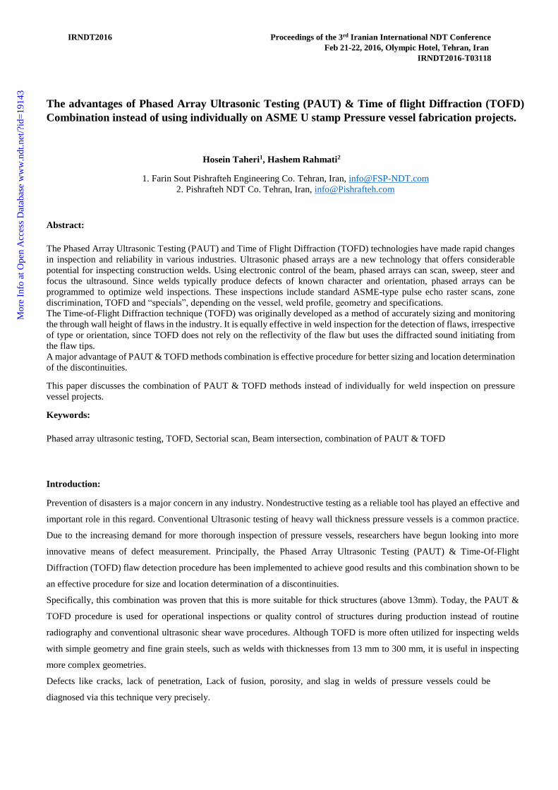
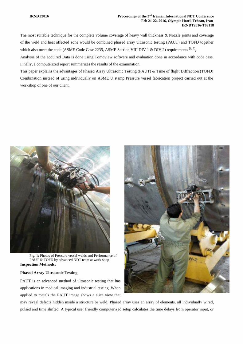
Fig. 1: Photos of Pressure vessel welds and Performance of PAUT & TOFD by advanced NDT team at work shop
Inspection Methods:
Phased Array Ultrasonic Testing
PAUT is an advanced method of ultrasonic testing that has
applications in medical imaging and industrial testing. When
applied to metals the PAUT image shows a slice view that
may reveal defects hidden inside a structure or weld. Phased array uses an array of elements, all individually wired,
pulsed and time shifted. A typical user friendly computerized setup calculates the time delays from operator input, or
an International NDT ConferenceIrani rdProceedings of the 3IRNDT2016 Feb 21-22, 2016, Olympic Hotel, Tehran, Iran
IRNDT2016-T03118
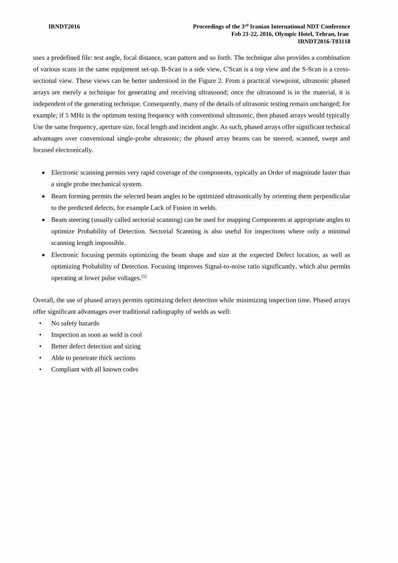
uses a predefined file: test angle, focal distance, scan pattern and so forth. The technique also provides a combination
of various scans in the same equipment set-up. B-Scan is a side view, C'Scan is a top view and the S-Scan is a cross-
sectional view. These views can be better understood in the Figure 2. From a practical viewpoint, ultrasonic phased
arrays are merely a technique for generating and receiving ultrasound; once the ultrasound is in the material, it is
independent of the generating technique. Consequently, many of the details of ultrasonic testing remain unchanged; for
example; if 5 MHz is the optimum testing frequency with conventional ultrasonic, then phased arrays would typically
Use the same frequency, aperture size, focal length and incident angle. As such, phased arrays offer significant technical
advantages over conventional single-probe ultrasonic; the phased array beams can be steered, scanned, swept and
focused electronically.
Electronic scanning permits very rapid coverage of the components, typically an Order of magnitude faster than
a single probe mechanical system.
Beam forming permits the selected beam angles to be optimized ultrasonically by orienting them perpendicular
to the predicted defects, for example Lack of Fusion in welds.
Beam steering (usually called sectorial scanning) can be used for mapping Components at appropriate angles to
optimize Probability of Detection. Sectorial Scanning is also useful for inspections where only a minimal
scanning length impossible.
Electronic focusing permits optimizing the beam shape and size at the expected Defect location, as well as
optimizing Probability of Detection. Focusing improves Signal-to-noise ratio significantly, which also permits
operating at lower pulse voltages.[5]
Overall, the use of phased arrays permits optimizing defect detection while minimizing inspection time. Phased arrays
offer significant advantages over traditional radiography of welds as well:
• No safety hazards
• Inspection as soon as weld is cool
• Better defect detection and sizing
• Able to penetrate thick sections
• Compliant with all known codes
an International NDT ConferenceIrani rdProceedings of the 3IRNDT2016 Feb 21-22, 2016, Olympic Hotel, Tehran, Iran
IRNDT2016-T03118
Fig. 2: Phased array Ultrasonic Testing Images
an International NDT ConferenceIrani rdProceedings of the 3IRNDT2016 Feb 21-22, 2016, Olympic Hotel, Tehran, Iran
IRNDT2016-T03118
Time of Flight Diffraction
Time of Flight Diffraction (TOFD) is an advanced automated computerized UT absent technique, used for in-
service inspection of welds for heavy walled pressure vessels. TOFD system is capable to scan, store and evaluate
flaw indications in terms of height, length and position with greater accuracy and is suitable for weld thickness
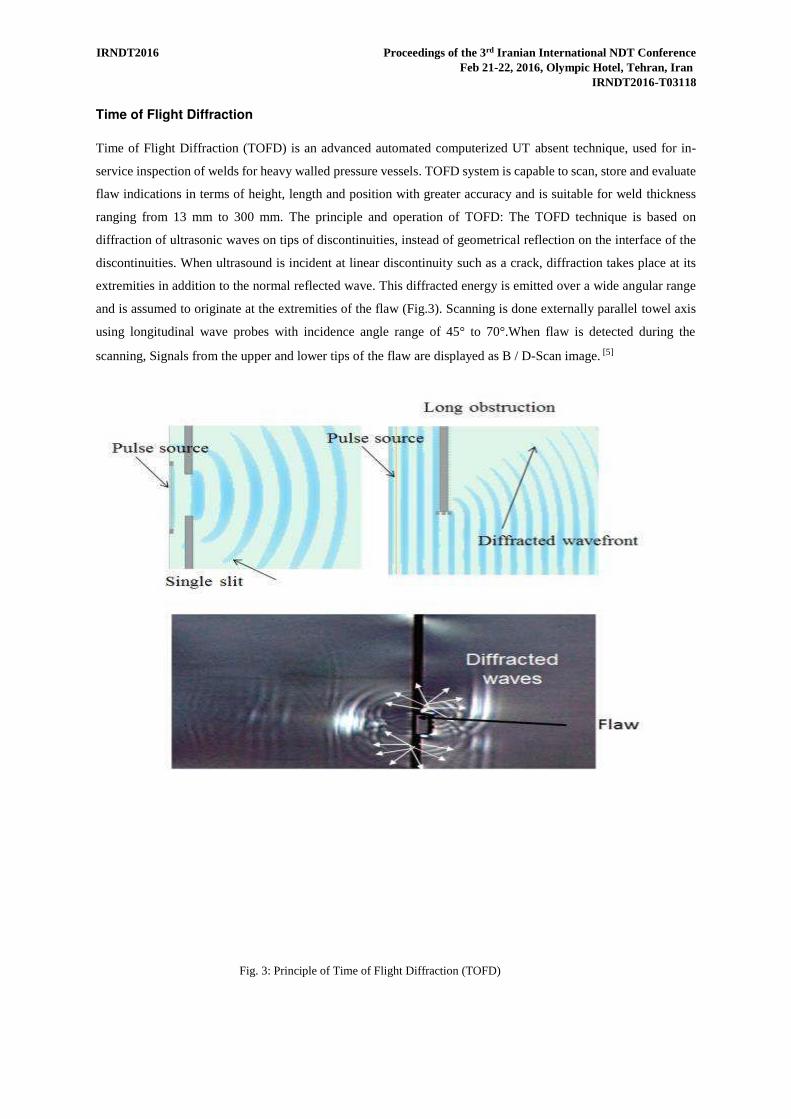
ranging from 13 mm to 300 mm. The principle and operation of TOFD: The TOFD technique is based on
diffraction of ultrasonic waves on tips of discontinuities, instead of geometrical reflection on the interface of the
discontinuities. When ultrasound is incident at linear discontinuity such as a crack, diffraction takes place at its
extremities in addition to the normal reflected wave. This diffracted energy is emitted over a wide angular range
and is assumed to originate at the extremities of the flaw (Fig.3). Scanning is done externally parallel towel axis
using longitudinal wave probes with incidence angle range of 45° to 70°.When flaw is detected during the
scanning, Signals from the upper and lower tips of the flaw are displayed as B / D-Scan image. [5]
Fig. 3: Principle of Time of Flight Diffraction (TOFD)
an International NDT ConferenceIrani rdProceedings of the 3IRNDT2016 Feb 21-22, 2016, Olympic Hotel, Tehran, Iran
IRNDT2016-T03118
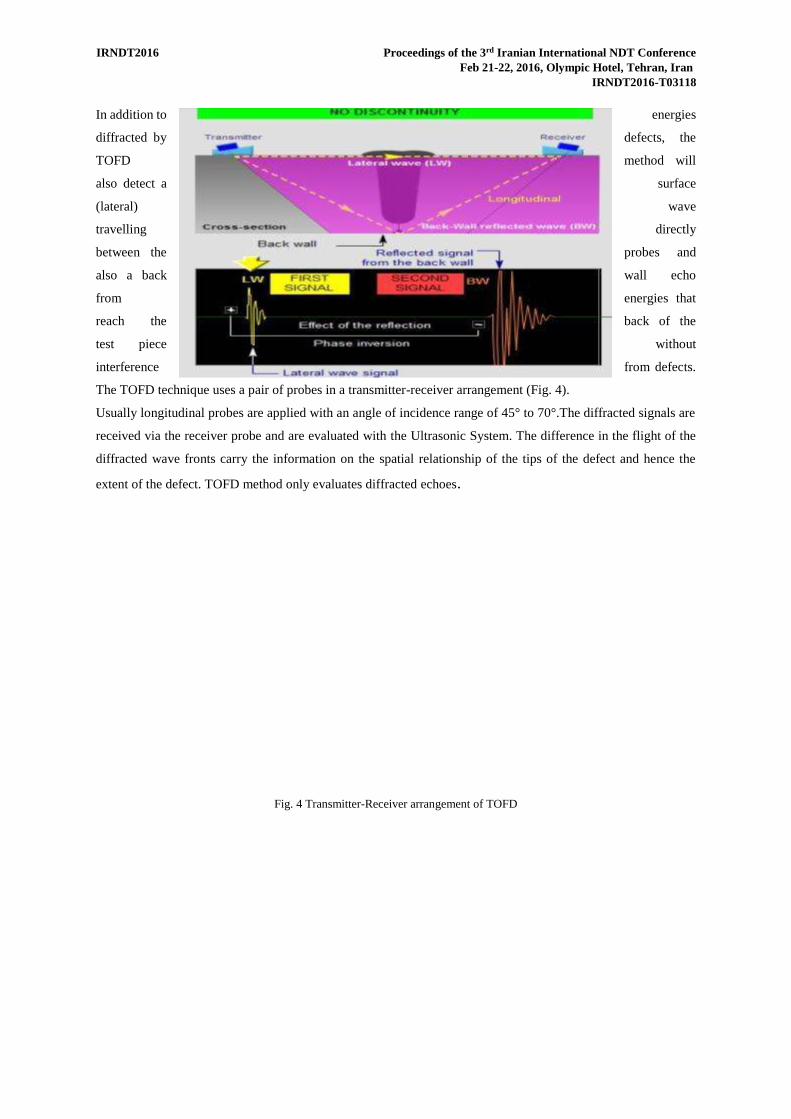
In addition to energies
diffracted by defects, the
TOFD method will
also detect a surface
(lateral) wave
travelling directly
between the probes and
also a back wall echo
from energies that
reach the back of the
test piece without
interference from defects.
The TOFD technique uses a pair of probes in a transmitter-receiver arrangement (Fig. 4).
Usually longitudinal probes are applied with an angle of incidence range of 45° to 70°.The diffracted signals are
received via the receiver probe and are evaluated with the Ultrasonic System. The difference in the flight of the
diffracted wave fronts carry the information on the spatial relationship of the tips of the defect and hence the
extent of the defect. TOFD method only evaluates diffracted echoes.
Fig. 4 Transmitter-Receiver arrangement of TOFD
an International NDT ConferenceIrani rdProceedings of the 3IRNDT2016 Feb 21-22, 2016, Olympic Hotel, Tehran, Iran
IRNDT2016-T03118
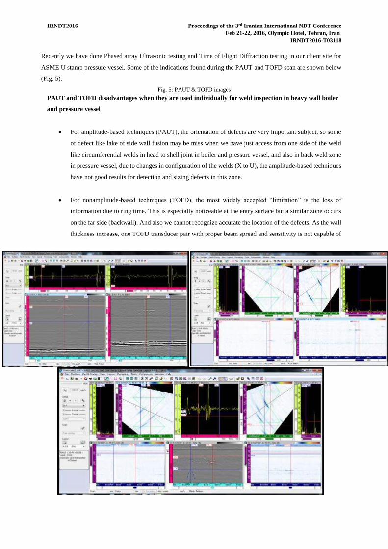
Recently we have done Phased array Ultrasonic testing and Time of Flight Diffraction testing in our client site for
ASME U stamp pressure vessel. Some of the indications found during the PAUT and TOFD scan are shown below
(Fig. 5).
Fig. 5: PAUT & TOFD images PAUT and TOFD disadvantages when they are used individually for weld inspection in heavy wall boiler
and pressure vessel
For amplitude-based techniques (PAUT), the orientation of defects are very important subject, so some
of defect like lake of side wall fusion may be miss when we have just access from one side of the weld
like circumferential welds in head to shell joint in boiler and pressure vessel, and also in back weld zone
in pressure vessel, due to changes in configuration of the welds (X to U), the amplitude-based techniques
have not good results for detection and sizing defects in this zone.
For nonamplitude-based techniques (TOFD), the most widely accepted “limitation” is the loss of
information due to ring time. This is especially noticeable at the entry surface but a similar zone occurs
on the far side (backwall). And also we cannot recognize accurate the location of the defects. As the wall
thickness increase, one TOFD transducer pair with proper beam spread and sensitivity is not capable of
an International NDT ConferenceIrani rdProceedings of the 3IRNDT2016 Feb 21-22, 2016, Olympic Hotel, Tehran, Iran
IRNDT2016-T03118
examining the entire weld volume. So, as the wall thickness increases, multiple TOFD transducer pairs
will have to be used.
Therefore, to examine fully, a heavy wall weld in a single pass, we offer a combined Multichannel
(TOFD+PAUT), zonal inspection, testing technique [1] See fig. 6
In short, multiple probes or probe combinations are fixed in a bracket in such an order that together they cover the
whole volume of the weld. Each probe or probe combination is directed to a certain portion of the weld and
together these probe units cover the whole volume of the weld. Probe characteristics are optimized in a way that
all possible weld anomalies are detected with high confidence. This principle is called "zonal discrimination” [2, 3,
4].
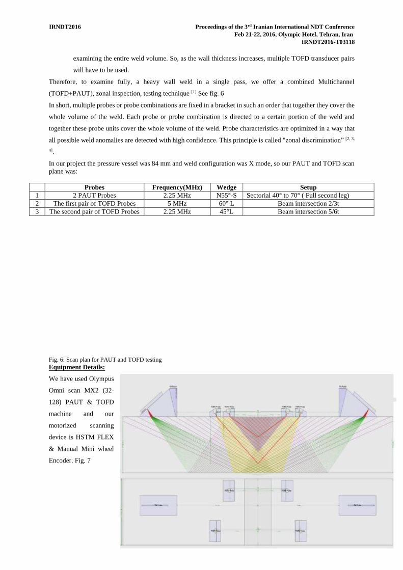
In our project the pressure vessel was 84 mm and weld configuration was X mode, so our PAUT and TOFD scan plane was:
Probes Frequency(MHz) Wedge Setup 1 2 PAUT Probes 2.25 MHz N55°-S Sectorial 40° to 70° ( Full second leg) 2 The first pair of TOFD Probes 5 MHz 60° L Beam intersection 2/3t 3 The second pair of TOFD Probes 2.25 MHz 45°L Beam intersection 5/6t
Fig. 6: Scan plan for PAUT and TOFD testing Equipment Details:
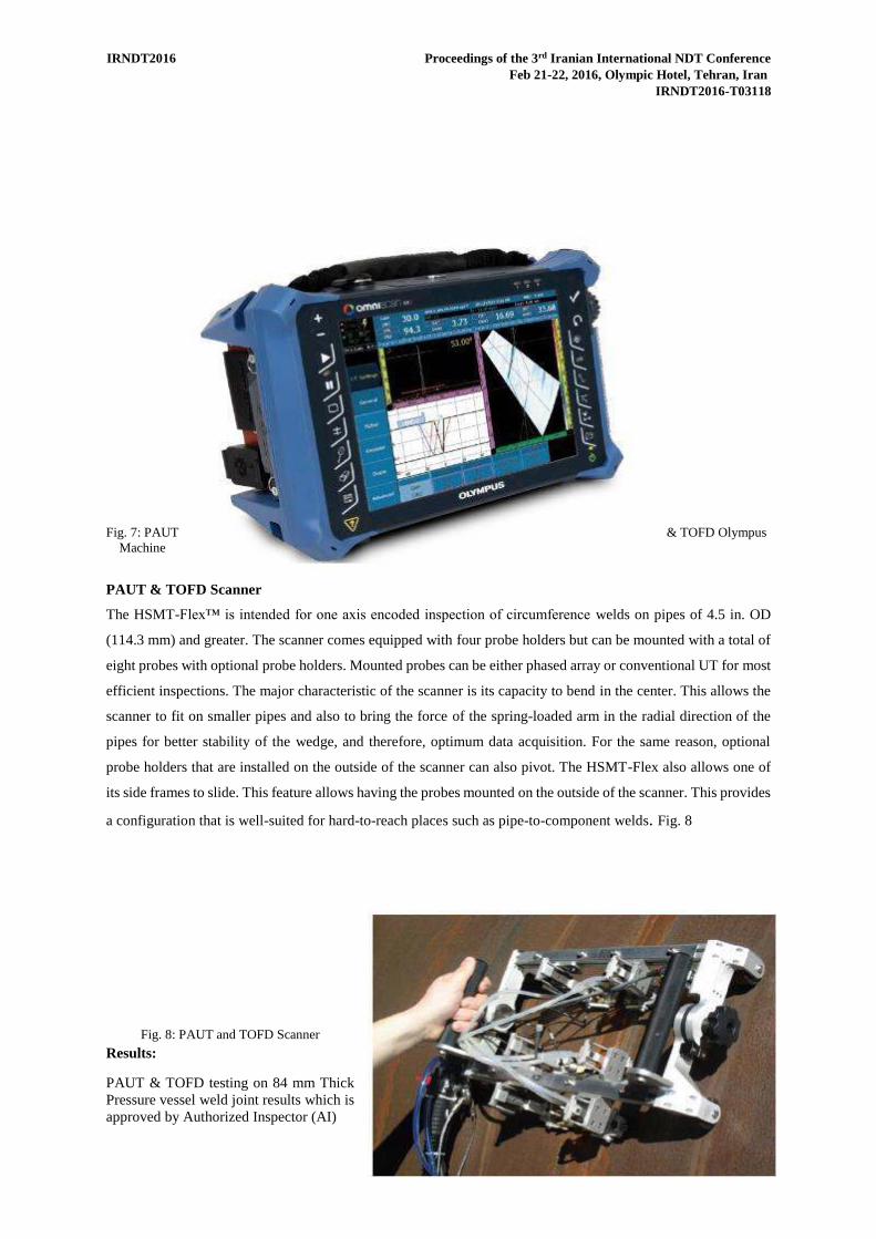
We have used Olympus
Omni scan MX2 (32-
128) PAUT & TOFD
machine and our
motorized scanning
device is HSTM FLEX
& Manual Mini wheel
Encoder. Fig. 7
an International NDT ConferenceIrani rdProceedings of the 3IRNDT2016 Feb 21-22, 2016, Olympic Hotel, Tehran, Iran
IRNDT2016-T03118
Fig. 7: PAUT & TOFD Olympus Machine
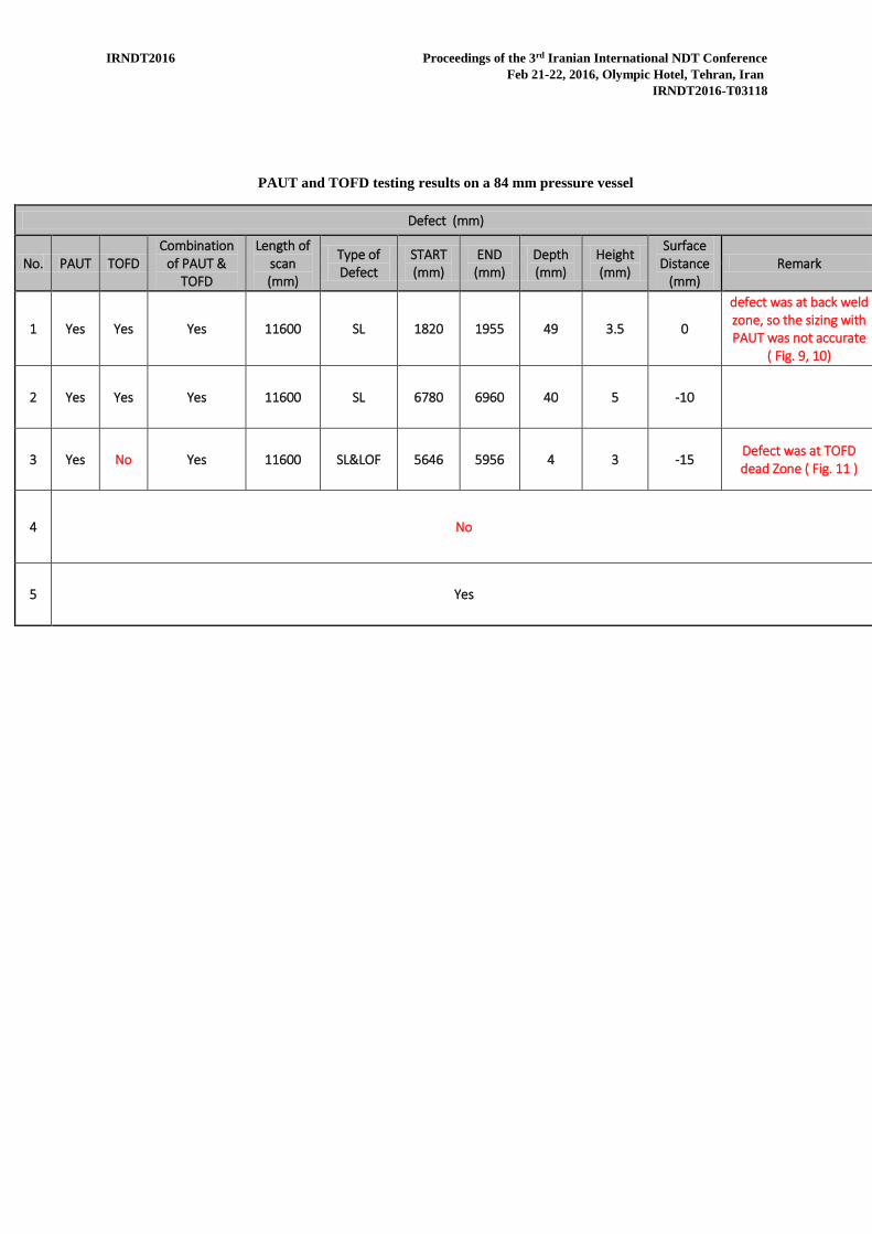
PAUT & TOFD Scanner
The HSMT-Flex™ is intended for one axis encoded inspection of circumference welds on pipes of 4.5 in. OD
(114.3 mm) and greater. The scanner comes equipped with four probe holders but can be mounted with a total of
eight probes with optional probe holders. Mounted probes can be either phased array or conventional UT for most
efficient inspections. The major characteristic of the scanner is its capacity to bend in the center. This allows the
scanner to fit on smaller pipes and also to bring the force of the spring-loaded arm in the radial direction of the
pipes for better stability of the wedge, and therefore, optimum data acquisition. For the same reason, optional
probe holders that are installed on the outside of the scanner can also pivot. The HSMT-Flex also allows one of
its side frames to slide. This feature allows having the probes mounted on the outside of the scanner. This provides
a configuration that is well-suited for hard-to-reach places such as pipe-to-component welds. Fig. 8
Fig. 8: PAUT and TOFD Scanner
Results:
PAUT & TOFD testing on 84 mm Thick Pressure vessel weld joint results which is approved by Authorized Inspector (AI)
an International NDT ConferenceIrani rdProceedings of the 3IRNDT2016 Feb 21-22, 2016, Olympic Hotel, Tehran, Iran
IRNDT2016-T03118
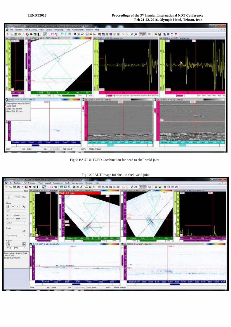
PAUT and TOFD testing results on a 84 mm pressure vessel
Defect (mm)
No. PAUT TOFD
Combination
of PAUT &
TOFD
Length of
scan
(mm)
Type of
Defect
START
(mm)
END
(mm)
Depth
(mm)
Height
(mm)
Surface
Distance
(mm)
Remark
1 Yes Yes Yes 11600 SL 1820 1955 49 3.5 0
defect was at back weld
zone, so the sizing with
PAUT was not accurate
( Fig. 9, 10)
2 Yes Yes Yes 11600 SL 6780 6960 40 5 -10
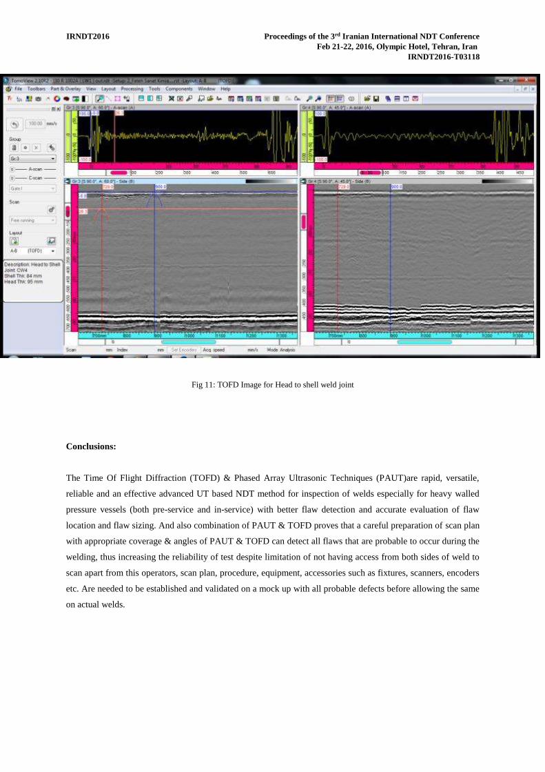
3 Yes No Yes 11600 SL&LOF 5646 5956 4 3 -15 Defect was at TOFD
dead Zone ( Fig. 11 )
4 No ……..
5 Yes
an International NDT ConferenceIrani rdProceedings of the 3IRNDT2016 Feb 21-22, 2016, Olympic Hotel, Tehran, Iran
IRNDT2016-T03118
Fig.9: PAUT & TOFD Combination for head to shell weld joint
Fig 10: PAUT Image for shell to shell weld joint
an International NDT ConferenceIrani rdProceedings of the 3IRNDT2016 Feb 21-22, 2016, Olympic Hotel, Tehran, Iran
IRNDT2016-T03118
Fig 11: TOFD Image for Head to shell weld joint
Conclusions:
The Time Of Flight Diffraction (TOFD) & Phased Array Ultrasonic Techniques (PAUT)are rapid, versatile,
reliable and an effective advanced UT based NDT method for inspection of welds especially for heavy walled
pressure vessels (both pre-service and in-service) with better flaw detection and accurate evaluation of flaw
location and flaw sizing. And also combination of PAUT & TOFD proves that a careful preparation of scan plan
with appropriate coverage & angles of PAUT & TOFD can detect all flaws that are probable to occur during the
welding, thus increasing the reliability of test despite limitation of not having access from both sides of weld to
scan apart from this operators, scan plan, procedure, equipment, accessories such as fixtures, scanners, encoders
etc. Are needed to be established and validated on a mock up with all probable defects before allowing the same
on actual welds.
an International NDT ConferenceIrani rdProceedings of the 3IRNDT2016 Feb 21-22, 2016, Olympic Hotel, Tehran, Iran
IRNDT2016-T03118
Reference:
1. ESBeam Tool from Eclipse Scientific, in Canada, http://www.eclipsescientific.com/Software/ESBeamTool/index.html
2. ASME Boiler & pressure vessel Code, Section V 2010, Article 4, Mandatory Appendix IV, " PHASED ARRAY MANUAL RASTER EXAMINATION TECHNIQUES USING LINEAR ARRAYS"
3. ASME Boiler & pressure vessel Code, Section V 2010, Article 4, Mandatory Appendix V," PHASED
ARRAY E-SCAN AND S-SCAN LINEAR SCANNING EXAMINATION TECHNIQUES"
4. ASME Boiler & pressure vessel Code, Section V 2010, Article 4, Mandatory Appendix III, " TIME-OF FLIGHT DIFFRACTION (TOFD) TECHNIQUE"
5. Advances in Phased array Ultrasonic Technology Applications, Olympus NDT (Dr. Michael D.C.
Moles), Published 2007
6. CASES OF ASME BOILER AND PRESSURE VESSEL CODE CASE 2235-9, Use of Ultrasonic Examination in Lieu of Radiography Section I; Section VIII, Divisions 1 and 2; and Section XII
7. ASME Boiler & pressure vessel Code, Section VIII 2010, Division I and II


![Non€¦ · and common NDT techniques. Keywords: Non-intrusive inspection [NII], Phased array ultrasonic testing [PAUT], Fitness – for – service [FFS], Computed radiography [CR],](https://img.pdfslide.net/doc/110x75/6039bfe787aa56292402f29d/non-and-common-ndt-techniques-keywords-non-intrusive-inspection-nii-phased.jpg)