Embed Size (px)
Citation preview
The Airborne Demonstrator for the Direct-Detection Doppler Wind LidarALADIN on ADM-Aeolus. Part I: Instrument Design and Comparison
to Satellite Instrument
OLIVER REITEBUCH, CHRISTIAN LEMMERZ, ENGELBERT NAGEL, AND ULRIKE PAFFRATH
Deutsches Zentrum fur Luft- und Raumfahrt, Institut fur Physik der Atmosphare, Oberpfaffenhofen, Germany
YANNIG DURAND AND MARTIN ENDEMANN
European Space Agency, Noordwijk, Netherlands
FREDERIC FABRE AND MARC CHALOUPY*
EADS Astrium, European Aeronautic Defense and Space Company, Toulouse, France
(Manuscript received 23 March 2009, in final form 29 June 2009)
ABSTRACT
The global observation of profiles of the atmospheric wind speed is the highest-priority unmet need for
global numerical weather prediction. Satellite Doppler lidar is the most promising candidate to meet the
requirements on global wind profile observations with high vertical resolution, precision, and accuracy. The
European Space Agency (ESA) decided to implement a Doppler wind lidar mission called the Atmospheric
Dynamics Mission Aeolus (ADM-Aeolus) to demonstrate the potential of the Doppler lidar technology and
the expected impact on numerical weather forecasting. An airborne prototype of the instrument on ADM-
Aeolus was developed to validate the instrument concept and retrieval algorithms with realistic atmospheric
observations before the satellite launch. It is the first airborne direct-detection Doppler lidar for atmospheric
observations, and it is operating at an ultraviolet wavelength of 355 nm. The optical design is described in
detail, including the single-frequency pulsed laser and the two spectrometers to resolve the Doppler fre-
quency shift from molecular Rayleigh and aerosol Mie backscatter. The airborne prototype is representative
of the spaceborne instrument, and their specific differences are discussed.
1. Introduction
In 1999, the European Space Agency (ESA) decided to
implement a Doppler wind lidar (DWL) mission called
the Atmospheric Dynamics Mission Aeolus (ADM-
Aeolus). The mission will provide profiles of one com-
ponent of the horizontal wind vector from ground up to
the lower stratosphere (20–30 km) with 0.5–2-km ver-
tical resolution and a precision of 1–3 m s21, depending
on altitude. A line-of-sight (LOS) wind profile will be
obtained every 200 km with a horizontal averaging length
of 50 km (ESA 1999, 2008; Stoffelen et al. 2005).
The ADM-Aeolus payload Atmospheric Laser Dopp-
ler Instrument (ALADIN) is based on a direct-detection
Doppler wind lidar operating at 355 nm (Schillinger et al.
2003; ESA 2008). The receiver consists of two spec-
trometers to determine the Doppler shift from the
spectrally broad Rayleigh molecular return and the
spectrally narrow Mie return from aerosols and clouds.
ALADIN will be the first wind lidar (Endemann et al.
2004; Morancais et al. 2004) and the first high-spectral-
resolution lidar (HSRL) in space (Ansmann et al. 2007;
Flamant et al. 2008).
A prelaunch campaign program for ADM-Aeolus was
established taking into account the following:
d The satellite instrument will be tested and character-
ized on ground in a clean-room environment, but
* Current affiliation: European Patent Office, Munich, Germany.
Corresponding author address: Oliver Reitebuch, Deutsches
Zentrum fur Luft- und Raumfahrt, Institut fur Physik der At-
mosphare, Oberpfaffenhofen, 82234 Wessling, Germany.
E-mail: [email protected]
VOLUME 26 J O U R N A L O F A T M O S P H E R I C A N D O C E A N I C T E C H N O L O G Y DECEMBER 2009
DOI: 10.1175/2009JTECHA1309.1
� 2009 American Meteorological Society 2501
without exposing it with atmospheric signals before
launch (Endemann et al. 2008).d Direct-detection Doppler wind lidars were operated
in the past from the ground (e.g., McGill et al. 1997b;
Delaval et al. 2000; Gentry et al. 2000; Yoe et al. 2003;
Shen et al. 2008), but no direct-detection Doppler lidar
was deployed on an airborne platform in a downward-
looking geometry as from space: likewise for coherent
Doppler lidars (Reitebuch et al. 2001; Weissmann
et al. 2005).d ALADIN combines new techniques that were not
implemented in a wind lidar before, such as a novel
combination of the molecular and aerosol spectrom-
eters, the use of a Fizeau interferometer for the nar-
rowband aerosol return, a sequential implementation
of the double-edge Fabry–Perot for molecular return,
and the use of two accumulation charge coupled de-
vices (ACCDs) as detectors.
The development of an airborne instrument dem-
onstrator was started by the European Aeronautic
Defence and Space Company (EADS-Astrium) and
Deutsches Zentrum fur Luft- und Raumfahrt (DLR)
in 2003, and it was called the ALADIN Airborne
Demonstrator (A2D). The main objective of the air-
borne instrument demonstrator is the validation of the
ALADIN instrument and performance models from
ground and from an airborne platform (Reitebuch et al.
2004, 2008; Durand et al. 2005, 2006). Furthermore, at-
mospheric observations with an ALADIN-type instru-
ment from various atmospheric scenes (e.g., clear air
without clouds, different cloud types or aerosol loadings,
surface returns) should be obtained to test, validate, and
optimize the retrieval and related quality-control algo-
rithms, as well as the calibration schemes for the space
instruments (Reitebuch et al. 2006; Dabas et al. 2008;
Flamant et al. 2008; Tan et al. 2008). An end-to-end
instrument simulator including the retrieval algorithms
was developed for the airborne demonstrator to assess
the radiometric and wind measurement performance
(Paffrath 2006). The simulator and the validation of the
radiometric performance are described in Paffrath et al.
(2009, hereafter Part II), whereas the measurement and
modeling of the sea surface reflectance under different
incidence angles at the wavelength of 355 nm with the
A2D is studied by Li et al. (2010).
The ALADIN airborne demonstrator is the first air-
borne direct-detection Doppler lidar for long ranges
and was deployed on an aircraft in October 2005 for the
first time. True-airspeed vector measurements at short
ranges of 50–150 m were performed already in 2004
by an airborne direct-detection Doppler lidar (Schmitt
et al. 2007). The ongoing development of an airborne
direct-detection Doppler lidar with a holographic scan-
ning device is described by Gentry et al. (2008).
Section 2 gives an overview of the principle of direct-
detection Doppler wind lidar and its various reali-
zations. Section 3 describes the design of the airborne
instrument demonstrator in detail, whereas section
4 discusses the representativeness of the airborne
ALADIN instrument design with respect to the satel-
lite instrument.
2. Principle of direct-detection Doppler wind lidar
DWL systems determine the LOS wind speed as
a function of range by detecting the change in wave-
length and frequency of the emitted laser pulse. The
moving atmospheric particles (aerosol, cloud particles,
and molecules) cause a frequency shift Df in the back-
scatter signal of the emitted laser frequency f0 because
of the Doppler effect, which is proportional to the ratio
of the wind velocity along the laser beam LOS vLOS and
the speed of light c of 2.998 3 108 m s21 with Df 5
2f0vLOS/c. An LOS wind velocity vLOS of 1 m s21 cor-
responds to a shift in frequency Df of 5.635 MHz and
wavelength shift Dl of 2.368 fm for the frequency f0 of
844.7 THz and wavelength l0 of 354.9 nm used by the
ALADIN instrument, respectively. The required accu-
racy in the measurement of the relative Doppler shift
Df/f0 is on the order of 1028 to achieve an accuracy of
1 m s21. Thus, a DWL requires spectrally narrow and
frequency-stabilized laser sources; therefore, single lon-
gitudinal mode operation is mandatory, which is chal-
lenging to achieve for airborne lidars because of aircraft
vibrations (cf section 3c).
On the one hand, the Doppler shift can be determined
from the spectrally narrowband Mie backscatter return
of aerosol or cloud particles, with the spectral width of
the emitted laser pulse and slightly broadened by at-
mospheric turbulence. This results in typical line widths
of a few m s21 up to 10 m s21 full width at half maxi-
mum (FWHM) for the narrowband Mie return in-
dependent from the chosen laser wavelength, which can
be converted to the more usual line width in units of
frequency by the earlier equation for Doppler shift.
Coherent or heterodyne Doppler wind lidars usually
operate at near-infrared wavelengths (1, 1.5–1.6, or
2 mm) by using solid-state or fiber lasers or operate at
infrared wavelengths (10.6 mm) with CO2 gas lasers.
Coherent wind lidars spectrally resolve the narrowband
aerosol and cloud return by optically beating the back-
scattered signal with light from a continuous-wave local
oscillator laser. On the other hand, the Doppler shift can
be determined from the spectrally broadband Rayleigh–
Brillouin return of molecules, which is caused by the
2502 J O U R N A L O F A T M O S P H E R I C A N D O C E A N I C T E C H N O L O G Y VOLUME 26
thermal Brownian movement of the molecules modified
by Brillouin scattering in the atmosphere (Tenti et al.
1974; Dabas et al. 2008). Typical line widths for the
broadband Rayleigh return are in the range of 580–
690 m s21 FWHM for atmospheric temperatures of
2608 to 1308C; thus, they are two orders of magnitude
larger than the narrowband Mie return.
Direct-detection (also called incoherent) Doppler li-
dars operate usually at wavelengths provided by an
Nd:YAG laser in the near infrared at 1.06 mm (funda-
mental), in the visible at 0.532 mm (second harmonic),
or in the ultraviolet (UV) at 0.355 mm (third harmonic).
They can be used to determine the wind speed from
both the broadband Rayleigh and the narrowband Mie
backscatter.
Measuring global atmospheric winds from space was
initially proposed, and then its performance was simu-
lated for the coherent detection at 10.6 mm using CO2
lasers by Huffaker (1978) and Huffaker et al. (1984) and
for the direct-detection technique using frequency-
doubled Nd:YAG lasers at 532 nm by Abreu (1979).
ADM-Aeolus, with the direct-detection Doppler lidar
ALADIN, spectrally resolves both the Mie and Rayleigh
backscatter by using two spectrometers to sense the wind
velocity, both in regions with high aerosol loads and
clouds and in regions with very low aerosol content in the
upper troposphere or lower stratosphere up to 30 km,
yielded toward giving the most impact to numerical
weather prediction (Stoffelen et al. 2005; ESA 2008).
The principle of wind measurements with direct-
detection Doppler lidar was first described and realized
by Benedetti-Michelangeli et al. (1972) with a frequency-
stabilized argon ion laser emitting at 488 nm and a
spherical Fabry–Perot interferometer as spectral ana-
lyzer.1 Direct-detection Doppler lidar use one or more
narrowband filters and determine the Doppler fre-
quency shift from the transmitted signal strength
through this filter, which is called the edge technique
(Korb et al. 1992, 1998; McKay 1998a; Flesia and Korb
1999), or from the radial angular distribution or spatial
movement of the interference patterns (‘‘fringes’’) of an
interferometer, which is called the fringe-imaging tech-
nique (McKay 1998b; McGill and Spinhirne 1998 for
a comparative overview). Because of the difference in
spectral width of the Mie and Rayleigh atmospheric
signal by one to two orders of magnitude, the imple-
mentation of the interferometer must be optimized to
either the Mie or Rayleigh spectral line width. Because
the transmitted signals through the filters are the convo-
lution of the filter transmission curves and the spectrum
of the atmospheric backscattered signal, the spectral re-
sponse has to be characterized for both the narrowband
Mie and the broadband Rayleigh signal separately. In
addition, a correction for atmospheric temperature and
pressure has to be performed for Rayleigh wind re-
trievals (Dabas et al. 2008) because of the temperature-
dependent broadening of the Rayleigh line, which is
proportional toffiffiffiffi
Tp
, modified by the pressure dependent
Brillouin scattering (Tenti et al. 1974).
If the filter maximum is placed at the steepest slope of
the atmospheric spectral line (‘‘turning point’’ or edge),
then a Doppler frequency shift results in a maximum
change in filter transmission. An increase in sensitivity
and accuracy is achieved when two filters are symmet-
rically placed around the spectral line maximum in both
edges of the spectrum. The double-edge technique was
pioneered by Chanin et al. (1989) and Garnier and
Chanin (1992) for stratospheric winds using the broad-
band molecular return with a laser wavelength of
532 nm and by Korb et al. (1992, 1998) and Gentry et al.
(2000) for tropospheric winds using laser wavelengths of
1064 and 532 nm for the narrowband aerosol return and
355 nm for the molecular return.
The double-edge technique is widely used to de-
termine the Doppler shift from Rayleigh return in the
UV at 355 nm (Flesia et al. 2000; Gentry et al. 2000;
Imaki and Kobayashi 2005; Sun et al. 2008), as im-
plemented for ALADIN, or at visible wavelengths of
532 nm (Chanin et al. 1989; Garnier and Chanin 1992;
Souprayen et al. 1999; Sun et al. 2008). Double-edge li-
dar systems for observing the narrowband aerosol return
using 1064 nm were applied for lower tropospheric winds
(Korb et al. 1997; Xia et al. 2007; Shen et al. 2008) and at
355 nm as a combined HSRL and DWL by Imaki and
Kobayashi (2005). The fringe-imaging technique was
applied by Abreu et al. (1992), Fischer et al. (1995),
McGill et al. (1997a,b), Irgang et al. (2002), Dehring et al.
(2003), and Schmitt et al. (2007). The ADM-Aeolus in-
strument ALADIN uses the double-edge technique for
the molecular Rayleigh return and the fringe-imaging
technique for the aerosol Mie return.
The single-edge technique can be realized by using
iodine molecular absorption lines as narrowband filters
for both molecular and aerosol backscatter at 532 nm
(Liu et al. 1997, 2007; see comparative overview in She
et al. 2007) and were recently applied to measure sea
surface winds during the 2008 Olympic Games in Bejing,
China (Liu et al. 2008). The iodine filter technique is also
used for wind measurements up to 70 km (Fiedler et al.
1 These first atmospheric wind lidar observations (the authors
used the term ‘‘optical radar’’) were performed in 1971 at the
European Space Research Institute (ESRIN) in Frascati, Italy.
Today, ESRIN is part of ESA and will be responsible for the
ADM-Aeolus mission after commissioning phase following the
satellite launch scheduled for 2011.
DECEMBER 2009 R E I T E B U C H E T A L . 2503
2008). Combined wind and temperature measurements
up to 50 km with a Na double-edge magneto-optic filter
were reported recently (Huang et al. 2009). The use of
the Mach-Zehnder interferometers as spectral analyzers
was proposed for the narrowband aerosol signal by Liu
and Kobayashi (1996), proposed for the broadband mo-
lecular signal by Bruneau (2001), and demonstrated by
Bruneau et al. (2004), whereas a fringe-imaging Michelson
interferometer was proposed by Cezard et al. (2006).
3. Design and setup of the ALADIN airbornedemonstrator
The airborne instrument version A2D of the satellite
instrument ALADIN was developed by EADS-Astrium
and DLR from 2003 to 2007. The core of the A2D is
based on the ALADIN receiver and transmitter from
the predevelopment program of ESA (Durand et al.
2005, 2006), and is therefore representative of the actual
satellite instrument. The optical receiver of the A2D was
space qualified with respect to its thermal vacuum and
vibration environment during the predevelopment
phase. Differences between the airborne and satellite
instrument are discussed in section 4.
The first flights were performed in October 2005, and
the development phase of the A2D was finished in April
2007, where it was demonstrated that the required fre-
quency stability of the laser was achieved even with
considerable aircraft vibrations. The A2D and the DLR
coherent 2-mm wind lidar (Kopp et al. 2004; Weissmann
et al. 2005) were both installed on the DLR Falcon 20
aircraft in November 2007, which is the first time that
a coherent and a direct-detection Doppler wind lidar
were operated simultaneously onboard an aircraft
(Reitebuch et al. 2008).
a. Airborne instrument design
The A2D is a nonscanning lidar as the satellite in-
strument. Thus, only one LOS component of the three-
dimensional wind vector is measured in contrast to most
other direct-detection wind lidars, which are equipped
with a scanning device. The LOS wind is measured
perpendicular to the aircraft roll axis, with an off-nadir
angle of 208. The A2D is designed to be operated on the
DLR Falcon 20 aircraft, a twin-engine jet with a pres-
surized cabin allowing a maximum payload of 1.1 ton,
a flight altitude of up to 12 km, and range of up to
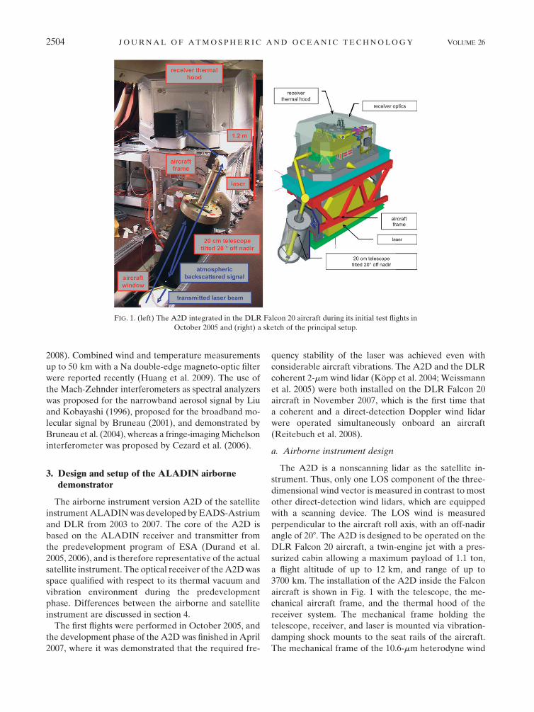
3700 km. The installation of the A2D inside the Falcon
aircraft is shown in Fig. 1 with the telescope, the me-
chanical aircraft frame, and the thermal hood of the
receiver system. The mechanical frame holding the
telescope, receiver, and laser is mounted via vibration-
damping shock mounts to the seat rails of the aircraft.
The mechanical frame of the 10.6-mm heterodyne wind
FIG. 1. (left) The A2D integrated in the DLR Falcon 20 aircraft during its initial test flights in
October 2005 and (right) a sketch of the principal setup.
2504 J O U R N A L O F A T M O S P H E R I C A N D O C E A N I C T E C H N O L O G Y VOLUME 26
infrared Doppler lidar (WIND; see Werner et al. 2001;
Reitebuch et al. 2001), which has proven its aircraft
vibration-damping behavior needed for coherent de-
tection, was adapted to hold the A2D laser, optical
receiver, and telescope.
The laser beam is directed toward the atmosphere via
a window in the bottom fuselage of the aircraft cabin.
The electronic units operating the A2D are installed in
19-in. aircraft racks and are controlled by two operators.
The total volume of the system is 3 m3, the weight is
550 kg, and the mean power consumption is 2.5 kW. Fi-
nite element simulations were performed to minimize
the overall weight, providing high stiffness for the trans-
mit and receive optical path, and to prove airworthiness.
The A2D can be operated from ground within a con-
tainer using the same mechanical setup as in the aircraft
with the telescope pointing toward the ground. Thus, an
additional reflecting mirror is installed to point the beam
toward the atmosphere up to 208 off-zenith angles.
b. Optical design overview
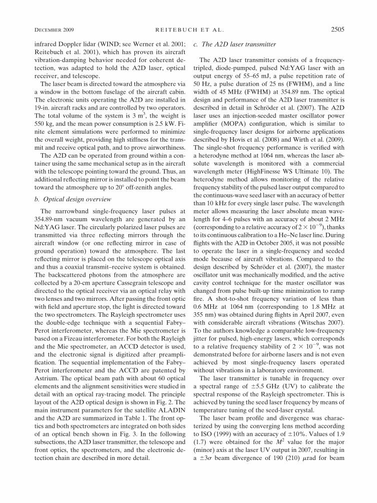
The narrowband single-frequency laser pulses at
354.89-nm vacuum wavelength are generated by an
Nd:YAG laser. The circularly polarized laser pulses are
transmitted via three reflecting mirrors through the
aircraft window (or one reflecting mirror in case of
ground operation) toward the atmosphere. The last
reflecting mirror is placed on the telescope optical axis
and thus a coaxial transmit–receive system is obtained.
The backscattered photons from the atmosphere are
collected by a 20-cm aperture Cassegrain telescope and
directed to the optical receiver via an optical relay with
two lenses and two mirrors. After passing the front optic
with field and aperture stop, the light is directed toward
the two spectrometers. The Rayleigh spectrometer uses
the double-edge technique with a sequential Fabry–
Perot interferometer, whereas the Mie spectrometer is
based on a Fizeau interferometer. For both the Rayleigh
and the Mie spectrometer, an ACCD detector is used,
and the electronic signal is digitized after preampli-
fication. The sequential implementation of the Fabry–
Perot interferometer and the ACCD are patented by
Astrium. The optical beam path with about 60 optical
elements and the alignment sensitivities were studied in
detail with an optical ray-tracing model. The principle
layout of the A2D optical design is shown in Fig. 2. The
main instrument parameters for the satellite ALADIN
and the A2D are summarized in Table 1. The front op-
tics and both spectrometers are integrated on both sides
of an optical bench shown in Fig. 3. In the following
subsections, the A2D laser transmitter, the telescope and
front optics, the spectrometers, and the electronic de-
tection chain are described in more detail.
c. The A2D laser transmitter
The A2D laser transmitter consists of a frequency-
tripled, diode-pumped, pulsed Nd:YAG laser with an
output energy of 55–65 mJ, a pulse repetition rate of
50 Hz, a pulse duration of 25 ns (FWHM), and a line
width of 45 MHz (FWHM) at 354.89 nm. The optical
design and performance of the A2D laser transmitter is
described in detail in Schroder et al. (2007). The A2D
laser uses an injection-seeded master oscillator power
amplifier (MOPA) configuration, which is similar to
single-frequency laser designs for airborne applications
described by Hovis et al. (2008) and Wirth et al. (2009).
The single-shot frequency performance is verified with
a heterodyne method at 1064 nm, whereas the laser ab-
solute wavelength is monitored with a commercial
wavelength meter (HighFinesse WS Ultimate 10). The
heterodyne method allows monitoring of the relative
frequency stability of the pulsed laser output compared to
the continuous-wave seed laser with an accuracy of better
than 10 kHz for every single laser pulse. The wavelength
meter allows measuring the laser absolute mean wave-
length for 4–6 pulses with an accuracy of about 2 MHz
(corresponding to a relative accuracy of 2 3 1029), thanks
to its continuous calibration to a He–Ne laser line. During
flights with the A2D in October 2005, it was not possible
to operate the laser in a single-frequency and seeded
mode because of aircraft vibrations. Compared to the
design described by Schroder et al. (2007), the master
oscillator unit was mechanically modified, and the active
cavity control technique for the master oscillator was
changed from pulse built-up time minimization to ramp
fire. A shot-to-shot frequency variation of less than
0.6 MHz at 1064 nm (corresponding to 1.8 MHz at
355 nm) was obtained during flights in April 2007, even
with considerable aircraft vibrations (Witschas 2007).
To the authors knowledge a comparable low-frequency
jitter for pulsed, high-energy lasers, which corresponds
to a relative frequency stability of 2 3 1029, was not
demonstrated before for airborne lasers and is not even
achieved by most single-frequency lasers operated
without vibrations in a laboratory environment.
The laser transmitter is tunable in frequency over
a spectral range of 65.5 GHz (UV) to calibrate the
spectral response of the Rayleigh spectrometer. This is
achieved by tuning the seed laser frequency by means of
temperature tuning of the seed-laser crystal.
The laser beam profile and divergence was charac-
terized by using the converging lens method according
to ISO (1999) with an accuracy of 610%. Values of 1.9
(1.7) were obtained for the M2 value for the major
(minor) axis at the laser UV output in 2007, resulting in
a 63s beam divergence of 190 (210) mrad for beam
DECEMBER 2009 R E I T E B U C H E T A L . 2505
diameters of 6.5 (5.6) mm. Because the receiver field of
view (FOV) is only 100 mrad, the higher laser beam di-
vergence results in a significant signal loss (see Part II).
After increasing the beam diameter and optimization of
the alignment through the power amplifier and higher-
harmonic crystals, an almost Gaussian beam profile with
M2 of 1.2 and a divergence of below 90 mrad (63s) was
obtained.
The seed- and power-laser diodes are temperature
stabilized with a water cooling system to 168 6 0.18C.
The heat of this water cooling system is removed to the
outside of the aircraft by a two-stage liquid cooling
system.
d. Telescope and front optics
The Cassegrain telescope is composed of a 200-mm
concave, aspheric primary mirror and a 75-mm convex,
spherical secondary mirror with a telescope focal length
of 1.5 m, resulting in an f-number of f/7.5. The transmit
path mirror is mounted on the optical axis of the tele-
scope at the backside of the secondary mirror. A pair of
lenses after the secondary mirror acts as an ocular,
turning the telescope into a focal system with a colli-
mated output beam and a magnification of 21.4. The
light is directed toward the optical receiver via a free
optical path relay consisting of two mirrors and two
lenses. In contrast, most other direct-detection lidar sys-
tems (e.g., Korb et al. 1997; Souprayen et al. 1999; Gentry
et al. 2000; Irgang et al. 2002; Imaki and Kobayashi 2005;
Liu et al. 2007; Xia et al. 2007) use fiber coupling between
telescope and spectrometers. The fiber coupling eases
optomechanical integration and stability and generates
uniform illumination of the spectrometers by spatial
mode scrambling of the atmospheric signal (Grund and
FIG. 2. Schematic optical layout of the A2D.
2506 J O U R N A L O F A T M O S P H E R I C A N D O C E A N I C T E C H N O L O G Y VOLUME 26
Eloranta 1991). Because the satellite instrument contains
no fiber coupling from the telescope to the receiver, it was
not implemented for the A2D. Significant transmission
losses up to 50% in the case of the ALADIN instrument
would be introduced by the use of nonpolarizating main-
taining, multimode fibers because of the polarization-
dependent receiver and spectrometer optics.
Polarizing optical elements turn the input circular
polarized light from the atmosphere into linear polar-
ized light. Depolarization in the atmosphere resulting
from aspherical particles (e.g., ice particles within cirrus
clouds or desert dust aerosol) will result in noncircular
polarized light and will be reflected inside the front
optics. Thus, depolarization within the atmosphere or
the optics will result in a corresponding signal loss at the
spectrometers.
Two filters for blocking visible and infrared light and
a 2.6-nm FWHM interference filter centered at 355 nm
are used to block solar background light. A circular di-
aphragm of 200 mm acts as a field stop within the front
optics and limits the FOV of the telescope to 100 mrad
at full angle. An aperture stop limits the beam diameter
at the entrance plane of the spectrometers to 20 mm
with a resulting divergence of 1 mrad (full angle), con-
serving the systems etendue (product of aperture and
divergence).
To monitor the frequency of the transmitted laser
pulse and to perform calibrations of the frequency-
dependent transmission of the spectrometers, a small
fraction of the UV light inside the laser is directed to-
ward an integrating sphere and coupled via a multimode
fiber (200-mm diameter, 4-m length) into the receiver
front optics, allowing adjustable signal levels by a vari-
able fiber attenuator. The fiber diameter and collimating
optics are designed so that the field and aperture stops
are fully illuminated by the laser internal reference. An
electro-optical modulator (Lasermetrics T1042) is used
to block the atmospheric path after laser-pulse emission
by a variable time of usually 3 ms, corresponding to
450 m, to avoid disturbances of the laser internal refer-
ence measurement by atmospheric signal and to avoid
saturation of the detectors at short ranges.
To control the angular coalignment between the
transmit and receive path (optical axis of telescope, field
stop, and spectrometers) a UV-sensitive charge-coupled
device (CCD) camera (Sony XC-EU50CE) monitors
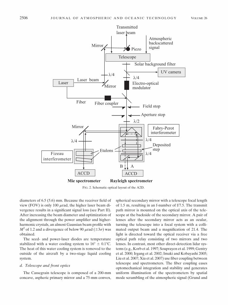
TABLE 1. Specifications of the satellite ALADIN and measured performance of the A2D.
Satellite ALADIN A2D
Platform Satellite Container or DLR Falcon aircraft
Alt 408 km Ground or 8–12 km flight alt
LOS pointing 37.68 off nadir 08, 15–208 off zenith (ground)
208 off nadir (aircraft)
Min vertical resolution 250 m for 2.1 ms at 37.68 off nadir 315 m for 2.1 ms at 08 zenith
Laser transmitter Nd:YAG, frequency-tripled, diode-pumped
Wavelength 354.9 nm 354.89 nm
Operation Burst mode Continuous
Pulse repetition rate 100 Hz 50 Hz
Energy per pulse 120 mJ 55–65 mJ
Laser line width ,50 MHz (FWHM) 45 MHz (FWHM)
Pulse-to-pulse frequency
stability in the UV
,4 MHz rms over 7 s ,1.8 MHz rms over 14 s
4.5 MHz peak to peak
Laser divergence 12 mrad 80–90 mrad for 63s, 99.7%
(190–210 mrad until November 2007)
Laser beam diameter 1.5 m 16 mm (99.7%)
(8 mm until November 2007, 99.7%)
Laser output polarization Circular left
Laser internal reference path Free path with aberration
generator
Multi mode fiber with polarizer
Telescope and receiver Transceiver telescope; same
transmit and receive path
Receiver Cassegrain telescope
Separate transmit and receive paths
Telescope diameter 1.5 m 0.2 m
Receiver FOV 19 mrad 100 mrad
Background blocking filter
bandwidth FWHM
1 nm 2.6 nm
Mie spectrometer Fringe-imaging Fizeau interferometer, 16 spectral channels
Rayleigh spectrometer Double-edge Fabry–Perot interferometer, 2 filters, sequential
Detector Accumulation CCD, quantum efficiency 0.85
DECEMBER 2009 R E I T E B U C H E T A L . 2507
the integrated backscatter from the atmosphere. The
spot position on the CCD camera corresponds to dif-
ferent incidence angles of the backscattered signal with
respect to the receive path optical axis. The deviation of
the center of gravity of the backscattered atmospheric
signal on the CCD camera from a reference position,
which corresponds to the center of the field stop, is
used to automatically steer the direction of the trans-
mit path mirror by three piezoelectric actuators. This
coalignment loop centers the integrated atmospheric
backscatter from the laser onto the receiver FOV and
compensates for thermoelastic and laser pointing drifts.
The angular stability of the active coalignment loop
depends on the measured laser beam motion in the at-
mosphere, which is mainly caused by atmospheric tur-
bulence and partly caused by laser beam pointing jitter.
For ground operation, the measured angular stability is
between 61 to 65 mrad and about 65 mrad for airborne
operation, compared to the total atmospheric FOV of
100 mrad. The active coalignment is specifically needed
for the A2D and not for the satellite instrument (cf.
section 4).
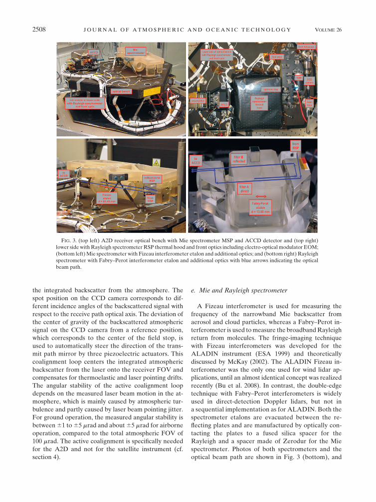
e. Mie and Rayleigh spectrometer
A Fizeau interferometer is used for measuring the
frequency of the narrowband Mie backscatter from
aerosol and cloud particles, whereas a Fabry–Perot in-
terferometer is used to measure the broadband Rayleigh
return from molecules. The fringe-imaging technique
with Fizeau interferometers was developed for the
ALADIN instrument (ESA 1999) and theoretically
discussed by McKay (2002). The ALADIN Fizeau in-
terferometer was the only one used for wind lidar ap-
plications, until an almost identical concept was realized
recently (Bu et al. 2008). In contrast, the double-edge
technique with Fabry–Perot interferometers is widely
used in direct-detection Doppler lidars, but not in
a sequential implementation as for ALADIN. Both the
spectrometer etalons are evacuated between the re-
flecting plates and are manufactured by optically con-
tacting the plates to a fused silica spacer for the
Rayleigh and a spacer made of Zerodur for the Mie
spectrometer. Photos of both spectrometers and the
optical beam path are shown in Fig. 3 (bottom), and
FIG. 3. (top left) A2D receiver optical bench with Mie spectrometer MSP and ACCD detector and (top right)
lower side with Rayleigh spectrometer RSP thermal hood and front optics including electro-optical modulator EOM;
(bottom left) Mie spectrometer with Fizeau interferometer etalon and additional optics; and (bottom right) Rayleigh
spectrometer with Fabry–Perot interferometer etalon and additional optics with blue arrows indicating the optical
beam path.
2508 J O U R N A L O F A T M O S P H E R I C A N D O C E A N I C T E C H N O L O G Y VOLUME 26
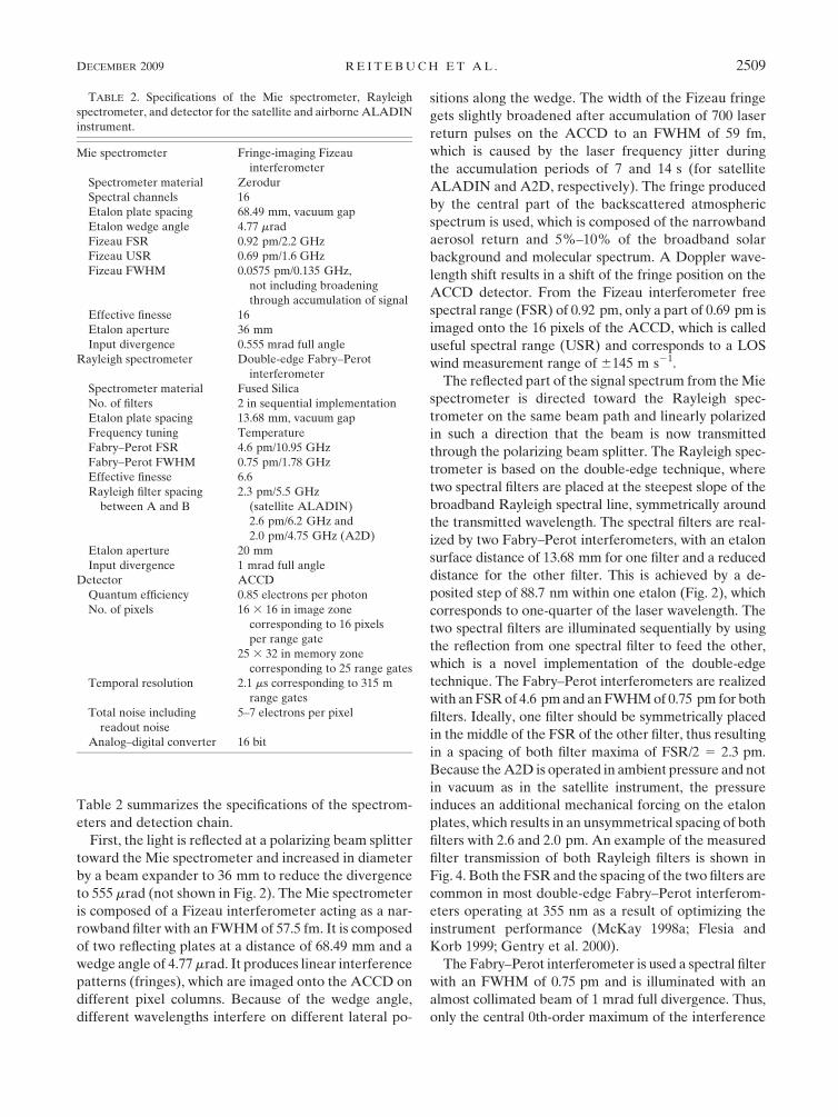
Table 2 summarizes the specifications of the spectrom-
eters and detection chain.
First, the light is reflected at a polarizing beam splitter
toward the Mie spectrometer and increased in diameter
by a beam expander to 36 mm to reduce the divergence
to 555 mrad (not shown in Fig. 2). The Mie spectrometer
is composed of a Fizeau interferometer acting as a nar-
rowband filter with an FWHM of 57.5 fm. It is composed
of two reflecting plates at a distance of 68.49 mm and a
wedge angle of 4.77 mrad. It produces linear interference
patterns (fringes), which are imaged onto the ACCD on
different pixel columns. Because of the wedge angle,
different wavelengths interfere on different lateral po-
sitions along the wedge. The width of the Fizeau fringe
gets slightly broadened after accumulation of 700 laser
return pulses on the ACCD to an FWHM of 59 fm,
which is caused by the laser frequency jitter during
the accumulation periods of 7 and 14 s (for satellite
ALADIN and A2D, respectively). The fringe produced
by the central part of the backscattered atmospheric
spectrum is used, which is composed of the narrowband
aerosol return and 5%–10% of the broadband solar
background and molecular spectrum. A Doppler wave-
length shift results in a shift of the fringe position on the
ACCD detector. From the Fizeau interferometer free
spectral range (FSR) of 0.92 pm, only a part of 0.69 pm is
imaged onto the 16 pixels of the ACCD, which is called
useful spectral range (USR) and corresponds to a LOS
wind measurement range of 6145 m s21.
The reflected part of the signal spectrum from the Mie
spectrometer is directed toward the Rayleigh spec-
trometer on the same beam path and linearly polarized
in such a direction that the beam is now transmitted
through the polarizing beam splitter. The Rayleigh spec-
trometer is based on the double-edge technique, where
two spectral filters are placed at the steepest slope of the
broadband Rayleigh spectral line, symmetrically around
the transmitted wavelength. The spectral filters are real-
ized by two Fabry–Perot interferometers, with an etalon
surface distance of 13.68 mm for one filter and a reduced
distance for the other filter. This is achieved by a de-
posited step of 88.7 nm within one etalon (Fig. 2), which
corresponds to one-quarter of the laser wavelength. The
two spectral filters are illuminated sequentially by using
the reflection from one spectral filter to feed the other,
which is a novel implementation of the double-edge
technique. The Fabry–Perot interferometers are realized
with an FSR of 4.6 pm and an FWHM of 0.75 pm for both
filters. Ideally, one filter should be symmetrically placed
in the middle of the FSR of the other filter, thus resulting
in a spacing of both filter maxima of FSR/2 5 2.3 pm.
Because the A2D is operated in ambient pressure and not
in vacuum as in the satellite instrument, the pressure
induces an additional mechanical forcing on the etalon
plates, which results in an unsymmetrical spacing of both
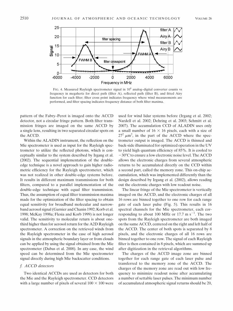
filters with 2.6 and 2.0 pm. An example of the measured
filter transmission of both Rayleigh filters is shown in
Fig. 4. Both the FSR and the spacing of the two filters are
common in most double-edge Fabry–Perot interferom-
eters operating at 355 nm as a result of optimizing the
instrument performance (McKay 1998a; Flesia and
Korb 1999; Gentry et al. 2000).
The Fabry–Perot interferometer is used a spectral filter
with an FWHM of 0.75 pm and is illuminated with an
almost collimated beam of 1 mrad full divergence. Thus,
only the central 0th-order maximum of the interference
TABLE 2. Specifications of the Mie spectrometer, Rayleigh
spectrometer, and detector for the satellite and airborne ALADIN
instrument.
Mie spectrometer Fringe-imaging Fizeau
interferometer
Spectrometer material Zerodur
Spectral channels 16
Etalon plate spacing 68.49 mm, vacuum gap
Etalon wedge angle 4.77 mrad
Fizeau FSR 0.92 pm/2.2 GHz
Fizeau USR 0.69 pm/1.6 GHz
Fizeau FWHM 0.0575 pm/0.135 GHz,
not including broadening
through accumulation of signal
Effective finesse 16
Etalon aperture 36 mm
Input divergence 0.555 mrad full angle
Rayleigh spectrometer Double-edge Fabry–Perot
interferometer
Spectrometer material Fused Silica
No. of filters 2 in sequential implementation
Etalon plate spacing 13.68 mm, vacuum gap
Frequency tuning Temperature
Fabry–Perot FSR 4.6 pm/10.95 GHz
Fabry–Perot FWHM 0.75 pm/1.78 GHz
Effective finesse 6.6
Rayleigh filter spacing
between A and B
2.3 pm/5.5 GHz
(satellite ALADIN)
2.6 pm/6.2 GHz and
2.0 pm/4.75 GHz (A2D)
Etalon aperture 20 mm
Input divergence 1 mrad full angle
Detector ACCD
Quantum efficiency 0.85 electrons per photon
No. of pixels 16 3 16 in image zone
corresponding to 16 pixels
per range gate
25 3 32 in memory zone
corresponding to 25 range gates
Temporal resolution 2.1 ms corresponding to 315 m
range gates
Total noise including
readout noise
5–7 electrons per pixel
Analog–digital converter 16 bit
DECEMBER 2009 R E I T E B U C H E T A L . 2509
pattern of the Fabry–Perot is imaged onto the ACCD
detector, not a circular fringe pattern. Both filter trans-
mission fringes are imaged on the same ACCD by
a single lens, resulting in two separated circular spots on
the ACCD.
Within the ALADIN instrument, the reflection on the
Mie spectrometer is used as input for the Rayleigh spec-
trometer to utilize the reflected photons, which is con-
ceptually similar to the system described by Irgang et al.
(2002). The sequential implementation of the double-
edge technique is a novel approach to gain higher radio-
metric efficiency for the Rayleigh spectrometer, which
was not realized in other double-edge systems before.
It results in different maximum transmissions for both
filters, compared to a parallel implementation of the
double-edge technique with equal filter transmission.
Thus, the assumption of equal filter transmission maxima
made for the optimization of the filter spacing to obtain
equal sensitivity for broadband molecular and narrow-
band aerosol signal (Garnier and Chanin 1992; Korb et al.
1998; McKay 1998a; Flesia and Korb 1999) is not longer
valid. The sensitivity to molecular return is about one-
third higher than for aerosol return for the A2D Rayleigh
spectrometer. A correction on the retrieved winds from
the Rayleigh spectrometer in the case of high aerosol
signals in the atmospheric boundary layer or from clouds
can be applied by using the signal obtained from the Mie
spectrometer (Dabas et al. 2008). In any case, the wind
speed can be determined from the Mie spectrometer
signal directly during high Mie backscatter conditions.
f. ACCD detectors
Two identical ACCDs are used as detectors for both
the Mie and the Rayleigh spectrometer. CCD detectors
with a large number of pixels of several 100 3 100 were
used for wind lidar systems before (Irgang et al. 2002;
Nardell et al. 2002; Dehring et al. 2003; Schmitt et al.
2007). The accumulation CCD of ALADIN uses only
a small number of 16 3 16 pixels, each with a size of
272 mm2, in the part of the ACCD where the spec-
trometer output is imaged. The ACCD is thinned and
back-side illuminated for optimized operation in the UV
to yield high quantum efficiency of 85%. It is cooled to
2308C to ensure a low electronic noise level. The ACCD
allows the electronic charges from several atmospheric
returns to be accumulated directly on the CCD within
a second part, called the memory zone. This on-chip ac-
cumulation, which was implemented differently than the
design described by Irgang et al. (2002), allows reading
out the electronic charges with low readout noise.
The linear fringe of the Mie spectrometer is vertically
imaged on the ACCD, and the electronic charges of all
16 rows are binned together to one row for each range
gate of each laser pulse (Fig. 5). This results in 16
spectral channels for the Mie spectrometer, each cor-
responding to about 100 MHz or 17.7 m s21. The two
spots from the Rayleigh spectrometer are both imaged
on the same ACCD, centered on the right and left half of
the ACCD. The center of both spots is separated by 8
pixels, and the electronic charges of all 16 rows are
binned together to one row. The signal of each Rayleigh
filter is then contained in 8 pixels, which are summed up
after digitization in the retrieval algorithms.
The charges of the ACCD image zone are binned
together for each range gate of each laser pulse and
transferred to the memory zone of the ACCD. The
charges of the memory zone are read out with low fre-
quency to minimize readout noise after accumulating
a number of settable laser pulses. The minimum number
of accumulated atmospheric signal returns should be 20,
FIG. 4. Measured Rayleigh spectrometer signal in 104 analog–digital converter counts vs
frequency in megahertz for direct path (filter A), reflected path (filter B), and fitted Airy
function for each filter; filter cross point indicates frequency where wind measurements are
performed, and filter spacing indicates frequency distance of both filter maxima.
2510 J O U R N A L O F A T M O S P H E R I C A N D O C E A N I C T E C H N O L O G Y VOLUME 26
to limit the number of lost pulses to 10%, because a time
of two laser-pulse acquisitions is needed for read-out.
Because the memory zone contains 25 rows, a maximum
number of 25 range gates can be acquired with the
ACCD. The background light and the laser internal
reference signal for the A2D are acquired in one range
gate each. The transfer time from the image to the
memory zone of the ACCD limits the minimum tem-
poral resolution of one range gate to 2.1 ms, which cor-
responds to a range resolution of 315 m. The timing
sequences of both ACCDs are programmable, giving
flexibility in range gate resolution within one profile for
both the Mie and Rayleigh return independently and
also for the number of accumulated shots on the ACCD.
The photons at the input of the ACCD are converted
to electrons with a quantum efficiency of 85% and a total
noise of about 5–7 electrons per pixel, thus allowing
quasi-photon counting. Detectors used for DWL oper-
ating in the UV as photomultiplier tubes usually provide
a much smaller quantum efficiency of about 25% (Imaki
and Kobayashi 2005; Gentry et al. 2000, 2008). After
preamplification, the charges are digitized within 16 bit.
In addition to the range-gated mode, the ACCD can be
used in an imaging mode, where raw images of 16 3 16
pixels are acquired without any on-chip accumulation.
This mode is mainly used for alignment and verification
purposes.
g. Thermal design and spectrometer thermal tuning
The A2D receiver is enclosed in a thermal hood (Fig. 1),
which is temperature stabilized better than 20–40 mK
by utilizing five Peltier thermoelectric elements for cool-
ing and heating. A sixth Peltier element is used for cooling
both ACCD detectors to 2308C. The Rayleigh spec-
trometer is additionally enclosed inside the receiver (see
Fig. 3, top right) and heated to achieve a temperature
stability of 610 mK. The Rayleigh spectrometer is
made of Silica with a thermal expansion coefficient of
5.5 3 1027 K21, resulting in a frequency change of
465 MHz K21. In contrast to that, the Mie spectrome-
ter is made of Zerodur, which provides a 10–20 times
lower thermal expansion coefficient. To center the Mie
spectrometer USR onto the filter crossing point of the
Rayleigh spectrometer, the operating temperature of
the Rayleigh spectrometer is adapted. For measuring
the frequency-dependent Rayleigh and Mie filters trans-
mission, both the Rayleigh and the Mie spectrometer are
kept at constant temperatures and the emitted laser fre-
quency is changed in discrete frequency steps of usually
250 MHz over one full FSR of 11 GHz of the Rayleigh
spectrometer (Fig. 4).
The wind measurements are performed at a laser
frequency at the filter crossing point of the Rayleigh
spectrometer and the center of the Mie spectrometer
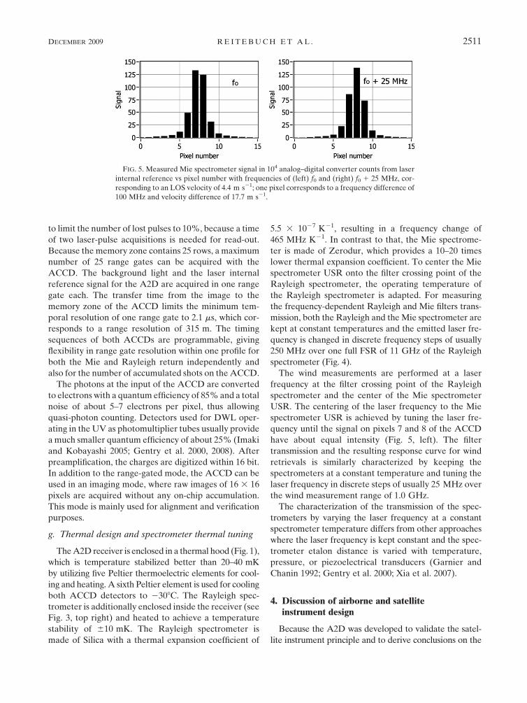
USR. The centering of the laser frequency to the Mie
spectrometer USR is achieved by tuning the laser fre-
quency until the signal on pixels 7 and 8 of the ACCD
have about equal intensity (Fig. 5, left). The filter
transmission and the resulting response curve for wind
retrievals is similarly characterized by keeping the
spectrometers at a constant temperature and tuning the
laser frequency in discrete steps of usually 25 MHz over
the wind measurement range of 1.0 GHz.
The characterization of the transmission of the spec-
trometers by varying the laser frequency at a constant
spectrometer temperature differs from other approaches
where the laser frequency is kept constant and the spec-
trometer etalon distance is varied with temperature,
pressure, or piezoelectrical transducers (Garnier and
Chanin 1992; Gentry et al. 2000; Xia et al. 2007).
4. Discussion of airborne and satelliteinstrument design
Because the A2D was developed to validate the satel-
lite instrument principle and to derive conclusions on the
FIG. 5. Measured Mie spectrometer signal in 104 analog–digital converter counts from laser
internal reference vs pixel number with frequencies of (left) f0 and (right) f0 1 25 MHz, cor-
responding to an LOS velocity of 4.4 m s21; one pixel corresponds to a frequency difference of
100 MHz and velocity difference of 17.7 m s21.
DECEMBER 2009 R E I T E B U C H E T A L . 2511
satellite instrument alignment, calibration, testing, and
especially the retrieval algorithms, it was important to
design the A2D as similarly as possible to the satellite
instrument. A predevelopment program for the satellite
ALADIN instrument receiver and laser transmitter was
initiated by ESA, resulting in a prototype for the satellite
receiver and a breadboard version of the laser transmitter
(Durand et al. 2005, 2006). The ACCD, the detection
electronic of the A2D, and in particular the receiver spec-
trometers design and implementation are almost identical
to the satellite flight model. The laser transmitter princi-
ple with a injection-seeded, frequency-tripled Nd:YAG
in MOPA configuration is similar for the satellite and
airborne version, although the actual implementation is
different. A detailed description of the satellite instru-
ment design, specification, and implementation is found
in ESA (2008, 45–75), complemented by an end-to-end
performance simulation of the satellite instrument (Leike
et al. 2001; Marseille and Stoffelen 2003).
A comparative overview of the airborne and satellite
instrument parameters is provided in Table 1. Main
differences of the A2D to the satellite instrument are the
telescope, the transmit and receive optics, and the laser
transmitter implementation. A 0.2-m Cassegrain tele-
scope with an f-number of f/7.5 is used for the A2D and
a coaxial, separate laser transmit path. A 1.5-m tele-
scope with an f-number of f/0.9 in transceiver configu-
ration is implemented for the satellite, where the same
telescope is used for the transmit and receive path, re-
sulting in a laser beam diameter of 1.5 m and a di-
vergence of 12 mrad at the telescope output. The satellite
instrument FOV is limited by the field stop to 19 mrad,
compared to 100 mrad for the A2D. The transceiver
telescope at the satellite allows a very small FOV
without the need of active coalignment, which is nec-
essary for the A2D. Because of the transceiver telescope
configuration for the satellite, a mechanism is needed to
optically block the receiver spectrometers during laser-
pulse emission. In contrast, the airborne front optics
include an electro-optical modulator for suppression of
the near-field signal and a CCD camera for active
coalignment of transmit–receive path, which is not
needed for the satellite instrument. The coalignment
performance strongly influences the incidence angle on
both spectrometers and thus the retrieved Doppler fre-
quency shift for the A2D. Because of the random vari-
ation of the coalignment (cf. section 3d) the wind
random error for the A2D is above the level expected
for shot-noise limited detection. To achieve this random
error limit, it is planned to correct the retrieved wind
values by a parameter characterizing the incidence an-
gles on the spectrometers derived from the output of the
UV camera inside the airborne front optics.
The airborne version uses a fiber coupling unit for the
internal reference signal, whereas the satellite version
uses free path propagation. For the satellite instrument,
the laser internal reference signal is read out for every
single laser pulse, because the time between emission
and acquisition is sufficiently long, with about 3 ms. For
the airborne instrument, the laser internal reference
signal is accumulated on the ACCD as for the atmo-
spheric range gates. The time between emission and first
useful atmospheric range gate of 3 ms would be not suf-
ficient to read out the ACCD for every single laser pulse.
Both Mie and Rayleigh spectrometers, the ACCD
detectors, preamplifier, and detection unit are almost
identical between airborne and satellite versions, except
for some minor details in implementation resulting from
different operation environments (vacuum versus air-
craft cabin or ground pressure) and optimization of the
flight-model instrument compared to the predevelopment
model. The vacuum versus pressurized operation results
in an important difference in the Rayleigh filter frequency
spacing of 2.3 pm for vacuum compared to 2.6 pm, which
was measured during ambient pressure. This results in
different response slopes used for the wind retrievals.
The satellite laser emits laser pulses with an energy of
120 mJ at 354.9 nm and a pulse repetition rate of 100 Hz,
and it operates in burst-mode, where the laser power
amplifier diodes are switched off for 15 s, followed by
a warm-up period of 6 s, and then operate during wind
measurements for 7 s (Cosentino et al. 2004; ESA 2008).
The A2D laser emits pulses with 60 mJ at 354.89 nm at
a repetition rate of 50 Hz continuously. The principle of
burst-mode operation is obtained for the A2D data ac-
quisition, because a total of 700 laser pulses is acquired
by the detection unit during 14 s, followed by a temporal
gap of 4 s for the A2D resulting from data read out and
transfer.
The range-corrected energy aperture product is more
than 20 times larger for the A2D than for the satellite
instrument for an altitude of 10 km and off-nadir angles.
The different range-dependent signal dynamics are dis-
cussed in Part II. Different off-nadir angles of 37.68 (sat-
ellite), 208 (airborne), and 158–208 (ground) result in
different vertical range gate resolutions of 250 (satellite),
296 (airborne) and 304 m (ground, 158 zenith) for the same
minimum temporal resolution of 2.1 ms of the ACCD.
In the case of airborne and ground-based operation,
the atmospheric region of interest is close to the lidar
while it is at large ranges for satellite lidars (e.g., 500 km
for ADM-Aeolus on a 408 km orbit with 37.68 off nadir
angle). Thus, any effect in the near field of the lidar within
the first few kilometers (e.g., telescope overlap or range
dependency of spectrometer illumination) is not present
for the satellite system. On the other hand, effects of the
2512 J O U R N A L O F A T M O S P H E R I C A N D O C E A N I C T E C H N O L O G Y VOLUME 26
satellite orbital movement with respect to the earth’s
surface have to be compensated (e.g., latitude-dependent
earth rotation with a maximum at the equator of 464 m s21
or satellite rotations around its roll axis during laser-pulse
travel time).
5. Summary and conclusions
The design of the airborne prototype of the Doppler
wind lidar instrument on ADM-Aeolus is described.
The single-frequency pulsed transmitter is based on
a frequency-tripled Nd:YAG and achieves 60 mJ at
50 Hz with a frequency stability for every single laser
pulse of better than 2 MHz, even under aircraft vibra-
tions. To the authors’ knowledge, a comparable low-
frequency jitter for pulsed, high-energy lasers, which
corresponds to a relative frequency stability of 2 3 1029,
was not demonstrated before for airborne lasers.
The Doppler frequency shift from molecular Rayleigh
backscatter is spectrally resolved by the double-edge
method using a Fabry–Perot interferometer in a new
sequential implementation for both filters. A Fizeau
interferometer, which was not used before for atmo-
spheric wind measurements, senses the Doppler shift
from the narrowband aerosol Mie return. An ACCD
detector with on-chip accumulation of the atmospheric
signal from several laser pulses achieves photon-counting
capabilities with high quantum efficiency of 85%.
The instrument optical throughput and thus radio-
metric performance was validated with observations
compared to end-to-end simulations, which is described
in Part II. Wind retrieval algorithms for the Rayleigh
and Mie spectrometer output were developed and
compared to ground-based observations from radio-
sondes and radar wind profilers. A detailed description
of the instrument calibration and the wind retrieval al-
gorithms and an examination of random and system-
atic wind errors will be given in a forthcoming paper.
The high similarities of the airborne demonstrator for
ALADIN and the satellite instrument allow validation
and optimization of the wind retrieval algorithms and
calibration of the instrument with realistic atmospheric
signals before launch of the satellite.
Acknowledgments. The development of the ALADIN
airborne demonstrator (A2D) was funded by ESA and
DLR and performed by a team at DLR and EADS-
Astrium (France, Germany), with contributions by
E. Chinal, C. Hoeltzel, P. Mahnke, R. Treichel, T. Schroder,
and C. Wuhrer. The review of the development activi-
ties by M. Alpers, A. Dabas, P. Flamant, D. Huber,
H. Nett, O. LeRille, R. Meynart, A. Stoffelen, A. Straume,
and M. Vaughan are highly acknowledged.
REFERENCES
Abreu, V. J., 1979: Wind measurements from an orbital platform
using a lidar system with incoherent detection: An analysis.
Appl. Opt., 18, 2992–2997.
——, J. E. Barnes, and P. B. Hayes, 1992: Observation of winds
with an incoherent lidar detector. Appl. Opt., 31, 4509–4514.
Ansmann, A., U. Wandinger, O. Le Rille, D. Lajas, and
A. G. Straume, 2007: Particle backscatter and extinction
profiling with the spaceborne high-spectral-resolution Dopp-
ler lidar ALADIN: Methodology and simulations. Appl. Opt.,
46, 6606–6622.
Benedetti-Michelangeli, G., F. Congeduti, and G. Fiocco, 1972:
Measurement of aerosol motion and wind velocity in the lower
troposhere by Doppler optical radar. J. Atmos. Sci., 29, 906–910.
Bruneau, D., 2001: Mach-Zehnder interferometer as a spectral
analyzer for molecular Doppler wind lidar. Appl. Opt., 38,
391–399.
——, A. Garnier, A. Hertzog, and J. Porteneuve, 2004: Wind-
velocity lidar measurements by use of a Mach-Zehnder in-
terferometer, comparison with a Fabry-Perot interferometer.
Appl. Opt., 38, 173–182.
Bu, L., K. Shan, X. Huang, J. Liu, J. Zhou, and W. Chen, 2008:
Direct-detection wind lidar system based on Fizeau in-
terferometer. Proc. 24th Int. Laser Radar Conf., Boulder, CO,
International Radiation Commission, 64–67.
Cezard, N., A. Dolfi-Bouteyre, J. P. Huignard, and P. Flamant,
2006: A 355-nm Rayleigh Mie lidar using two Michelson in-
terferometers as spectral analyzers for multi-purpose near-
field measurements. Proc. 23rd Int. Laser Radar Conf., Nara,
Japan, International Radiation Commission, 31–34.
Chanin, M. L., A. Garnier, A. Hauchecorne, and J. Porteneuve,
1989: A Doppler lidar for measuring winds in the middle at-
mosphere. Geophys. Res. Lett., 16, 1273–1276.
Cosentino, A., and Coauthors, 2004: All-solid-state laser trans-
mitter for space based lidar applications. Proc. 22nd Int. Laser
Radar Conf., Matera, Italy, International Radiation Com-
mission, 61–64.
Dabas, A., M. L. Denneulin, P. Flamant, C. Loth, A. Garnier, and
A. Dolfi-Bouteyre, 2008: Correcting winds measured with
a Rayleigh Doppler lidar from pressure and temperature ef-
fects. Tellus, 60A, 206–215.
Dehring, M. T., C. A. Nardell, J. C. Pavlich, P. B. Hays, and I. Dors,
2003: Performance and comparison of 532-nm and 355-nm
groundwinds lidars. Lidar Remote Sensing for Industry and
Environment Monitoring III, T. Itabe and Z. Liu, Eds., In-
ternational Society for Optical Engineering (SPIE Pro-
ceedings, Vol. 4893), 337–347.
Delaval, A., P. H. Flamant, M. Aupierre, P. Delville, and C. Loth,
2000: Intercomparison of wind profiling instruments during
the VALID field campaign. Proc. 20th Int. Laser Radar Conf.,
Vichy, France, International Radiation Commission, 101–104.
Durand, Y., R. Meynart, M. Endemann, E. Chinal, D. Morancais,
T. Schroder, and O. Reitebuch, 2005: Manufacturing of an
airborne demonstrator of ALADIN: The direct detection
Doppler wind lidar for ADM-Aeolus. Lidar Technologies,
Techniques, and Measurements for Atmospheric Remote Sensing,
U. N. Singh, Ed., International Society for Optical Engineering
(SPIE Proceedings, Vol. 5984), doi:10.1117/12.627789.
——, E. Chinal, M. Endemann, R. Meynart, O. Reitebuch, and
R. Treichel, 2006: ALADIN Airborne Demonstrator: a Dopp-
ler Wind Lidar to prepare ESA’s Aeolus Explorer Mission.
Earth Observing Systems XI, J. J. Butler, Ed., International
DECEMBER 2009 R E I T E B U C H E T A L . 2513
Society for Optical Engineering (SPIE Proceedings, Vol. 6296),
doi:10.1117/12.680958.
Endemann, M., P. Dubock, P. Ingmann, R. Wimmer, D. Morancais,
and D. Demuth, 2004: The ADM-Aeolus mission—The first
wind-lidar in space. Proc. 22nd Int. Laser Radar Conf., Matera,
Italy, International Radiation Commission, 953–956.
——, A. Culoma, D. Wernham, and W. Veith, 2008: Character-
ization and qualification status of the ADM-Aeolus mission.
Proc. 24th Int. Laser Radar Conf., Boulder, CO, International
Radiation Commission, 41–44.
ESA, 1999: The four candidate Earth Explorer core missions: 4.
Atmospheric Dynamics Mission. ESA SP-1233(4), 157 pp.
——, 2008: ADM-Aeolus Science Report, ESA Rep. SP-1311,
121 pp.
Fiedler, J., G. Baumgarten, and G. von Cossart, 2008: A middle
atmosphere lidar for multi-parameter measurements at a re-
mote site. Proc. 24th Int. Laser Radar Conf., Boulder, CO,
International Radiation Commission, 824–827.
Fischer, K. W., V. J. Abreu, W. R. Skinner, J. E. Barnes,
M. J. McGill, and T. D. Irgang, 1995: Visible wavelength
Doppler lidar for measurement of wind and aerosol profiles
during day and night. Opt. Eng., 34, 499–511.
Flamant, P. H., J. Cuesta, M. L. Denneulin, A. Dabas, and
D. Huber, 2008: ADM-Aeolus retrieval algorithms for aerosol
and cloud products. Tellus, 60A, 273–286.
Flesia, C., and C. L. Korb, 1999: Theory of the double-edge mo-
lecular technique for Doppler lidar wind measurement. Appl.
Opt., 38, 432–440.
——, ——, and C. Hirt, 2000: Double-edge molecular measurement
of lidar wind profiles at 355 nm. Opt. Lett., 25, 1466–1468.
Garnier, A., and M. L. Chanin, 1992: Description of a Doppler
Rayleigh LIDAR for measuring winds in the middle atmo-
sphere. Appl. Phys., 55B, 35–40.
Gentry, B. M., H. Chen, and S. X. Li, 2000: Wind measurements
with 355-nm molecular Doppler lidar. Opt. Lett., 25, 1231–1233.
——, and Coauthors, 2008: New technologies for direct detection
Doppler lidar: Status of the TWiLiTE airborne molecular
Doppler lidar project. Proc. 24th Int. Laser Radar Conf.,
Boulder, CO, International Radiation Commission, 239–243.
Grund, C., and E. Eloranta, 1991: Fiber-optic scrambler reduces the
bandpass range dependence of Fabry-Perot etalons used for
spectral analysis of lidar backscatter. Appl. Opt., 30, 2668–2670.
Hovis, F. E., J. Edelman, T. Schum, J. Rudd, and K. Andes, 2008:
Single frequency lasers for high altitude aircraft applications.
Proc. 24th Int. Laser Radar Conf., Boulder, CO, International
Radiation Commission, 3–6.
Huang, W., and Coauthors, 2009: Field demonstration of simul-
taneous wind and temperature measurements from 5 to
50 km with a Na double-edge magneto-optic filter in a multi-
frequency Doppler lidar. Opt. Lett., 34, 1552–1554.
Huffaker, R. M. Ed., 1978: Feasibility study of satellite-borne lidar
global wind monitoring system. NOAA Tech. Memo. ERL
WPL-37, 276 pp.
——, T. R. Lawrence, M. J. Post, J. T. Priestley, F. F. Hall,
R. A. Richter, and R. J. Keeler, 1984: Feasibility studies for
a global wind measuring satellite system (Windsat): Analysis
of simulated performance. Appl. Opt., 23, 2523–2536.
Imaki, M., and T. Kobayashi, 2005: Ultraviolet high-spectral-
resolution Doppler lidar for measuring wind field and aerosol
optical properties. Appl. Opt., 44, 6023–6030.
Irgang, T. D., P. B. Hays, and W. R. Skinner, 2002: Two-channel
direct detection Doppler lidar employing a charge-coupled
device as a detector. Appl. Opt., 41, 1145–1155.
ISO, 1999: Lasers and laser-related equipment—Test methods for
laser beam parameters. International Organization for Stan-
dardization Rep. 11146, 26 pp.
Kopp, F., S. Rahm, and I. Smalikho, 2004: Characterization of
aircraft wake vortices by 2-mm pulsed Doppler lidar. J. Atmos.
Oceanic Technol., 21, 194–206.
Korb, C. L., B. M. Gentry, and C. Weng, 1992: The edge technique:
Theory and application to the lidar measurement of atmo-
spheric winds. Appl. Opt., 31, 4202–4213.
——, ——, and S. X. Li, 1997: Edge technique Doppler lidar wind
measurements with high vertical resolution. Appl. Opt., 36,
5976–5983.
——, ——, ——, and C. Flesia, 1998: Theory of the double-edge
technique for Doppler lidar wind measurment. Appl. Opt., 37,
3097–3104.
Leike, I., J. Streicher, C. Werner, V. Banakh, I. Smalikho,
W. Wergen, and A. Cress, 2001: Virtual Doppler lidar in-
strument. J. Atmos. Oceanic Technol., 18, 1447–1456.
Li, Z., C. Lemmerz, U. Paffrath, O. Reitebuch, and B. Witschas,
2010: Airborne Doppler lidar investigation of the sea surface
reflectance at the ultraviolet wavelength of 355 nm. J. Atmos.
Oceanic Technol., in press.
Liu, Z., and T. Kobayashi, 1996: Differential discrimination tech-
nique for incoherent Doppler lidar to measure atmospheric
wind and backscatter ratio. Opt. Rev., 3, 47–52.
——, W. B. Chen, T. L. Zhang, J. W. Hair, and C. Y. She, 1997: An
incoherent Doppler lidar for ground-based atmospheric wind
profiling. Appl. Phys., 64B, 561–566.
——, B. Y. Liu, Z. G. Li, Z. A. Yan, S. H. Wu, and Z. B. Sun, 2007:
Wind measurements with incoherent Doppler lidar based on
iodine filters at night and day. Appl. Phys., 88B, 327–335.
——, ——, S. H. Wu, Z. G. Li, and Z. J. Wang, 2008: High spatial
and temporal resolution mobile incoherent Doppler lidar for
sea surface wind measurements. Opt. Lett., 33, 1485–1487.
Marseille, G. J., and A. Stoffelen, 2003: Simulation of wind profiles
from a space-borne Doppler wind lidar. Quart. J. Roy. Meteor.
Soc., 129, 3079–3098.
McGill, M. J., and J. D. Spinhirne, 1998: Comparison of two direct
detection Doppler lidar techniques. Opt. Eng., 37, 2675–2686.
——, W. R. Skinner, and T. D. Irgang, 1997a: Analysis techniques for
the recovery of winds and backscatter coefficients from a multi-
ple-channel incoherent Doppler lidar. Appl. Opt., 36, 1253–1268.
——, ——, and ——, 1997b: Validation of wind profiles measured
with incoherent Doppler lidar. Appl. Opt., 36, 1928–1939.
McKay, J. A., 1998a: Modeling of direct detection Doppler wind
lidar. I. The edge technique. Appl. Opt., 37, 6480–6486.
——, 1998b: Modeling of direct detection Doppler wind lidar. II.
The fringe imaging technique. Appl. Opt., 37, 6487–6493.
——, 2002: Assessment of a multibeam Fizeau wedge interfer-
ometer for Doppler wind lidar. Appl. Opt., 41, 6487–6493.
Morancais, D., F. Fabre, M. Schillinger, J.-C. Barthes, M. Endemann,
and A. Culoma, 2004: ALADIN: The first European lidar in
space. Proc. 22nd Int. Laser Radar Conf., Matera, Italy, In-
ternational Radiation Commission, 127–129.
Nardell, C. A., P. B. Hays, J. Pavlich, M. Dehring, and
G. Sypitkowski, 2002: GroundWinds New Hampshire and the
LIDARFest 2000 campaign. Remote Sensing for Industry and
Environment Monitoring II, U. N. Singh, Ed., International
Society for Optical Engineering (SPIE Proceedings, Vol.
4484), 36–50.
Paffrath, U., 2006: Performance assessment of the Aeolus Doppler
wind lidar prototype. Ph. D. dissertation, Technische Uni-
versitat Munchen and DLR Forschungsbericht, 137 pp.
2514 J O U R N A L O F A T M O S P H E R I C A N D O C E A N I C T E C H N O L O G Y VOLUME 26
——, C. Lemmerz, O. Reitebuch, B. Witschas, I. Nikolaus, and
V. Freudenthaler, 2009: The airborne demonstrator for
the direct-detection Doppler wind lidar ALADIN on
ADM-Aeolus. Part II: Simulations and Rayleigh receiver
radiometric performance. J. Atmos. Oceanic Technol., 26,
2516–2530.
Reitebuch, O., C. Werner, I. Leike, P. Delville, P. H. Flamant,
A. Cress, and D. Engelbart, 2001: Experimental validation of
wind profiling performed by the airborne 10-mm heterodyne
Doppler lidar WIND. J. Atmos. Oceanic Technol., 18, 1331–
1344.
——, E. Chinal, Y. Durand, M. Endemann, R. Meynart,
D. Morancais, and U. Paffrath, 2004: Development of an air-
borne demonstrator for ADM-Aeolus and campaign activities.
Proc. 22nd Int. Laser Radar Conf., Matera, Italy, International
Radiation Commission, 1007–1010.
——, U. Paffrath, D. Huber, and I. Leike, 2006: ADM-Aeolus level
1B products. ESA Rep. AE-RP-DLR-L1B-001, 62 pp. [Avail-
able online at http://eopi.esa.int/esa/esa?cmd5aodetail&aoname5
AeolusCalVal.]
——, and Coauthors, 2008: Pre-launch validation of ADM-Aeolus
with an airborne direct-detection wind lidar. Proc. 24th Int.
Laser Radar Conf., Boulder, CO, 41–44.
Schillinger, M., D. Morancais, F. Fabre, and A. J. Culoma, 2003:
ALADIN: The LIDAR instrument for the AEOLUS mis-
sion. Sensors, Systems, and Next-Generation Satellites VI,
H. Fujisada et al., Eds., International Society for Optical
Engineering (SPIE Proceedings, Vol. 4881), 40–51.
Schmitt, N. P., W. Rehm, T. Pistner, P. Zeller, H. Diehl, and
P. Nave, 2007: The AWIATOR airborne LIDAR turbulence
sensor. Aerosp. Sci. Technol., 11, 546–552.
Schroder, T., C. Lemmerz, O. Reitebuch, M. Wirth, C. Wuhrer, and
R. Treichel, 2007: Frequency jitter and spectral width of an
injection-seeded Q-switched Nd:YAG laser for a Doppler
wind lidar. Appl. Phys., 87B, 437–444.
She, C.-Y., J. Yue, Z.-A. Yan, J. W. Hair, J.-J. Guo, S.-H. Wu, and
Z.-S. Liu, 2007: Direct-detecion Doppler wind measurement
with a Cabannes-Mie lidar: A. Comparison between iodine
vapor filter and Fabry-Perot interferometer methods. Appl.
Opt., 46, 4434–4443.
Shen, F., H. Cha, D. Sun, D. Kim, and S. O. Kwon, 2008: Low
tropospheric wind measurement with Mie Doppler lidar. Opt.
Rev., 15, 204–209.
Souprayen, C., A. Garnier, A. Hertzog, A. Hauchecorne, and
J. Porteneuve, 1999: Rayleigh-Mie Doppler wind lidar for
atmospheric measurements. I. Instrumental setup, validation,
and first climatological results. Appl. Opt., 38, 2410–2421.
Stoffelen, A., and Coauthors, 2005: The Atmospheric Dynamics
Mission for global wind field measurement. Bull. Amer. Me-
teor. Soc., 86, 73–87.
Sun, D., F. Shen, H. Cha, D. Zhang, and J. Dong, 2008: De-
velopment of commercial wind lidar receiver. Proc. 24th Int.
Laser Radar Conf., Boulder, CO, International Radiation
Commission, 284–286.
Tan, D. G. H., and Coauthors, 2008: The ADM-Aeolus wind re-
trieval algorithms. Tellus, 60A, 191–205.
Tenti, G., C. D. Boley, and R. C. Desai, 1974: On the kinetic model
description of Rayleigh-Brillouin scattering from molecular
gases. Can. J. Phys., 52, 285–290.
Weissmann, M., R. Busen, A. Dornbrack, S. Rahm, and
O. Reitebuch, 2005: Targeted observations with an airborne
wind lidar. J. Atmos. Oceanic Technol., 22, 1706–1719.
Werner, C., and Coauthors, 2001: Wind infrared Doppler lidar
instrument. Opt. Eng., 40, 115–125.
Wirth, M., A. Fix, P. Mahnke, H. Schwarzer, F. Schrandt, and
G. Ehret, 2009: The airborne multi-wavelength water vapor
differential absorption lidar WALES: System design and
performance. Appl. Phys., 96B, 201–213.
Witschas, B., 2007: Characterisation of beam profile and frequency
stability of an injection-seeded Nd:YAG laser for a Doppler
wind lidar system. M.S. thesis, Department of Technical
Physics, University of Applied Sciences Munich, 102 pp.
Xia, H., D. Sun, Y. Yang, F. Shen, J. Dong, and T. Kobayashi, 2007:
Fabry-Perot interferometer based Mie Doppler lidar for low
tropospheric wind observation. Appl. Opt., 46, 7120–7130.
Yoe, J. G., and Coauthors, 2003: GroundWinds 2000 field cam-
paign: demonstration of new Doppler lidar technology and
wind lidar data intercomparison. Proc. SPIE Lidar Remote
Sensing for Industry and Environment Monitoring III, 4893,
Hangzhou, China, 327–336.
DECEMBER 2009 R E I T E B U C H E T A L . 2515