Embed Size (px)
Citation preview

SDC1VARTEH DC SERVO UNIT
Maintenance Manual
CONTENTS
1. Main features ............................................................... 22. Technical specification ................................................ 23. Operating conditions ................................................... 24. Compositions ............................................................... 25. Interface ....................................................................... 25.1. Details of signals ...................................................... 25.2. Interface connectors ................................................. 45.3. Connection of DC Servo Unit .................................. 46. Adjustment ................................................................. 106.1. Items available without removing of the front panel.106.2. Location of variable resistors, jumpers, te st points.. 107. Installation of DC servo unit ....................................... 107.1. Installation conditions .............................................. 107.2. Outer dimensions ..................................................... 10
ARTEH LTDNovember 2004
11 SVETLINA STR.8800 SLIVENBULGARIAwww.arteh-bg.com
TEL/FAX +359 44 687533TEL +359 887729888TEL +359 887794332
E-MAIL [email protected]
2
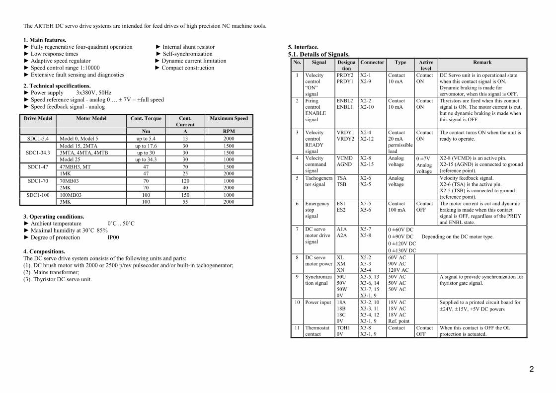
The ARTEH DC servo drive systems are intended for feed drives of high precision NC machine tools. 1. Main features. ► Fully regenerative four-quadrant operation ► Internal shunt resistor ► Low response times ► Self-synchronization ► Adaptive speed regulator ► Dynamic current limitation ► Speed control range 1:10000 ► Compact construction ► Extensive fault sensing and diagnostics
2. Technical specifications. ► Power supply 3x380V, 50Hz ► Speed reference signal - analog 0 … ± 7V = ±full speed ► Speed feedback signal - analog
Drive Model Motor Model Cont. Torque Cont. Current
Maximum Speed
Nm A RPM SDC1-5.4 Model 0, Model 5 up to 5.4 13 2000
Model 15, 2MTA up to 17.6 30 1500 SDC1-34.3 3MTA, 4MTA, 4MTB up to 30 30 1500
Model 25 up to 34.3 30 1000 SDC1-47 47MBH3, MT 47 70 1500
1MK 47 25 2000 SDC1-70 70MB03 70 120 1000
2MK 70 40 2000 SDC1-100 100MB03 100 150 1000
3MK 100 55 2000 3. Operating conditions. ► Ambient temperature 0˚C .. 50˚C ► Maximal humidity at 30˚C 85% ► Degree of protection IP00 4. Compositions. The DC servo drive system consists of the following units and parts: (1). DC brush motor with 2000 or 2500 p/rev pulsecoder and/or built-in tachogenerator; (2). Mains transformer; (3). Thyristor DC servo unit.
5. Interface. 5.1. Details of Signals.
No. Signal Designation
Connector Type Active level
Remark
1 Velocity control “ON” signal
PRDY2 PRDY1
X2-1 X2-9
Contact 10 mA
Contact ON
DC Servo unit is in operational state when this contact signal is ON. Dynamic braking is made for servomotor, when this signal is OFF.
2 Firing control ENABLE signal
ENBL2 ENBL1
X2-2 X2-10
Contact 10 mA
Contact ON
Thyristors are fired when this contact signal is ON. The motor current is cut, but no dynamic braking is made when this signal is OFF.
3 Velocity control READY signal
VRDY1 VRDY2
X2-4 X2-12
Contact 20 mA permissible load
Contact ON
The contact turns ON when the unit is ready to operate.
4 Velocity command signal
VCMD AGND
X2-8 X2-15
Analog voltage
0 ±7V Analog voltage
X2-8 (VCMD) is an active pin. X2-15 (AGND) is connected to ground (reference point).
5 Tachogenerator signal
TSA TSB
X2-6 X2-5
Analog voltage
Velocity feedback signal. X2-6 (TSA) is the active pin. X2-5 (TSB) is connected to ground (reference point).
6 Emergency stop signal
ES1 ES2
X5-5 X5-6
Contact 100 mA
Contact OFF
The motor current is cut and dynamic braking is made when this contact signal is OFF, regardless of the PRDY and ENBL state.
7 DC servo motor drive signal
A1A A2A
X5-7 X5-8
0 ±60V DC 0 ±90V DC Depending on the DC motor type. 0 ±120V DC 0 ±130V DC
8 DC servo motor power
XL XM XN
X5-2 X5-3 X5-4
60V AC 90V AC 120V AC
9 Synchronization signal
50U 50V 50W 0V
X3-5, 13 X3-6, 14 X3-7, 15 X3-1, 9
50V AC 50V AC 50V AC
A signal to provide synchronization for thyristor gate signal.
10 Power input 18A 18B 18C 0V
X3-2, 10 X3-3, 11 X3-4, 12 X3-1, 9
18V AC 18V AC 18V AC Ref. point
Supplied to a printed circuit board for ±24V, ±15V, +5V DC powers
11 Thermostat contact
TOH1 0V
X3-8 X3-1, 9
Contact Contact OFF
When this contact is OFF the OL protection is actuated.
X5 - M4 Screw terminal
3
1
2
4
5
DGND
50U
50U
6
7
8
50V
50V
50W
50W
TOH1
DGND
18A
18A
18B
18B
18C
18C
15
9
10
11
12
13
14
X3
N XL XM XN ES1 ES2 A1A A2A
1 2 3 4 5 6 7 8
X5
X3CANNONDB15M
X2CANNONDB15F
X4
8
7
5
4
TSB
VRDY1
2
1
3
ENBL2
PRDY2
VRDY2
6 TSA
VCMD
ENBL1
PRDY1 9
10
11
12
13
14
15
X2
XL
120° åë.
50U
XM
XN
50V
50W
Signal
ES
NO NO NOYES YES YES
PRDY
VRDY
ENBL
Signal Direction
Driver
Mashine tool
Driver
Driver
Driver
CNC
CNC
Thiristor work
CNC
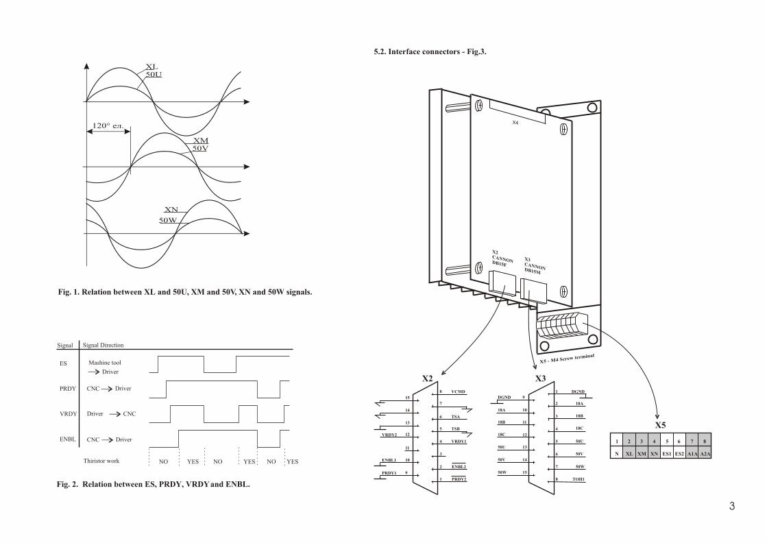
Fig. 1. Relation between XL and 50U, XM and 50V, XN and 50W signals.
Fig. 2. Relation between ES, PRDY, VRDY and ENBL.
5.2. Interface connectors - Fig.3.
3

4
PRDY2X2-1
X2-9
+24V
10K
+24V
+24V
10K
PRDY1
ENBL1
ENBL2X2-2
X2-10
VRDY1
VRDY2
X2-4
X2-12
VCMDX2-8
X2-15
TSB
TSAX2-6
X2-5
X2-14
ON
Signal
ENABLE
Signal
READY
Signal
VELOCITY
COMMAND
Signal
TSA
TSB
TACHOMETERGENERATORSignal fromCNC or built inthe motortachogenerator
PRDY2
RL
Emergency StopX5-5
X5-6
ES1
ES2
XL XM XN 50U 50V 50W 0V18A 0V 18B
X3-2
X3-10
X3-1
X3-9
X3-3
X3-11
X5-2 X5-3 X5-4 X3-5
X3-13
X3-6
X3-14
X3-7
X3-15
X3-1, X3-9
To DC Power Source To Sync. Circuit
TOH1
X3-8
To OL Alarm Circuit
18A 0V 18B 120L 120M 120N 50U 50V 50W 0V TOH2 TOH1
380R 380S 380T
MAINSTRANSFORMER
I>
AC 380V
X5-1
N
CNC DC Servo Unit
RL
A2A X5-8
A1A X5-7
TSA
TSB
TachoGenerator
PulseCoder
To CNC
DC ServoMotor
To the Velocity ErrorAmplifier
To the InterfaceCircuit
5.3. Connection of DC Servo Unit - Fig.4.

5
Notes: 1.Utilization of shielded wire is recommended for connection between CNC system and reference input (VCMD Velocity Command Signal). The shield has to be connected to X2-15 pin (AGND). 2.Utilization of shielded wire is recommended for connection between tachogenerator and velocity feedback input (TSA Signal). The shield has to be connected to X2-14 pin (AGND). If there is not built-in tachogenerator in DC motor the velocity feed back signal should be generated by CNC. 3.Use wires as short as possible. 4. The signal wires must be placed as far as possible from the power cables. CAUTION: Do not connect or disconnect any connector under voltage.

6
N XL XM XN ES1 ES2 A1A A2A
1 2 3 4 5 6 7 8
N XL XM XN ES1 ES2 A1A A2A
1 2 3 4 5 6 7 8
N R S T
X5 X5
21 22 23
36 37 33 34 35 39 40 41 38 30 31 32 27 28 29 24 25 26
TOH1 TOH2 18A 0V 18B 50U 50V 50W 0V 120L 120M 120N 120L 120M 120N 120L 120M 120N
380R 380S 380T
1 2 3 4 5
9 10 11 12
50W50V50U18C0V 18A 18B
6 7 8
151413
0V 18A 18B 18C 50U 50V 50W TOH1
8 7 6 5 4
15 14 13 12
VCMD TSA TSB
ENBL1AGND
AGND
AGND
PRDY2
3 2 1
91011
PRDY1
ENBL2
VRDY2
VRDY1
X2X3
Ê CNC
SDC1
1 2 3 4 5
9 10 11 12
50W50V50U18C0V 18A 18B
6 7 8
151413
0V 18A 18B 18C 50U 50V 50W TOH1
8 7 6 5 4
15 14 13 12
VCMD TSA TSB
ENBL1AGND
AGND
AGND
PRDY2
3 2 1
91011
PRDY1
ENBL2
VRDY2
VRDY1
X2X3
Ê CNC
SDC1
I>
I>
I>
PowerTransformer
Thermostatcontact
EmergencyStop
Notes:1. This diagram shows the case of 2-axises,Model 15 or Model 25 Motor type andA-type Power Transformer.
Fig. 5
Termalprotection
Termalprotection
Termalprotection

7Fig. 6
N XL XM XN ES1 ES2 A1A A2A
1 2 3 4 5 6 7 8
N XL XM XN ES1 ES2 A1A A2A
1 2 3 4 5 6 7 8
N
R S T
X5 X5
TOH1 0V 18A 18B 18C 50U 50V 50W 120L 120L120M 120M120N 120N
380R 380S 380T
1 2 3 4 5
9 10 11 12
50W50V50U18C0V 18A 18B
6 7 8
151413
0V 18A 18B 18C 50U 50V 50W TOH1
8 7 6 5 4
15 14 13 12
VCMD TSA TSB
ENBL1AGND
AGND
AGND
PRDY2
3 2 1
91011
PRDY1
ENBL2
VRDY2
VRDY1
X2X3
to CNC
SDC1
1 2 3 4 5
9 10 11 12
50W50V50U18C0V 18A 18B
6 7 8
151413
0V 18A 18B 18C 50U 50V 50W TOH1
8 7 6 5 4
15 14 13 12
VCMD TSA TSB
ENBL1AGND
AGND
AGND
PRDY2
3 2 1
91011
PRDY1
ENBL2
VRDY2
VRDY1
X2X3
to CNC
SDC1
R S T
R1 S1 T1A B C0TOH1 TOH2
I>
I> I>
PowerTransformerThermostat
contact
EmergencyStop
Notes:1. This diagram shows the case of 2-axises,Model 15 or Model 25 Motor type andARTEH 5VA Power Transformer.
Termalprotection
Termalprotection
Termalprotection

8Fig. 7
ArtTechArtTech
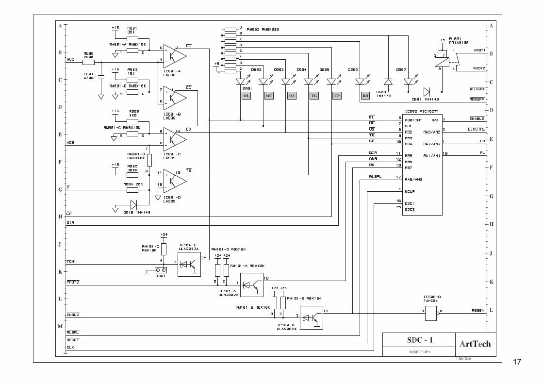
RD
EN
CP
TG
OS
OC
OL
Angle
I Limit
Gain
Offset
Tacho
P Term
I Term
Enable CtrlLS Gain
Tacho Scale
DC SERVO UNIT
SDC1
READY Indicator
ENABLE Indicator
PHASE FAILURE Indicator
TACHOMETER GENERATOR LOSS Ind.
OVERSPEED DETECTION Indicator
OVERLOAD DETECTION Indicator
OVERCURRENT DETECTION Indicator
INITIAL FIRING ANGLE adj.
CURRENT LIMIT adj. P501
SPEED CONTROLLER GAIN adj. P203
SPEED CONTROLLER OFFSET adj. P202
VELOCITY FEEDBACK GAIN adj. P201
P302
Prop. Term of PID Speed ControllerJ209J210
Integral Term of PID Speed Controller J211J212
Low Speed Gain of Speed Controller J202
Enable Speed Controller J201
Velocity Feedback Gain adj.
J207J206J205J204J203
Short J209, J210 or both of them for lower value of Proportional Term of PID Speed Controller
Short J211, J212 or both of them for higher value of Integral Term of PID Speed Controller
Short J202 to achieve lower Speed Controller Gain for lower speeds
Short J201 to set Speed Controller proportional
Use these jumpers to set appropriate gain of Velocity Feedback signal depending on the Tachometer V/rpm constant
J203
Motor type
Tacho constant, V/1000rpm
J204
J205
J206
J207
6
C
C
C
C
O
Model 5
9Fig. 8
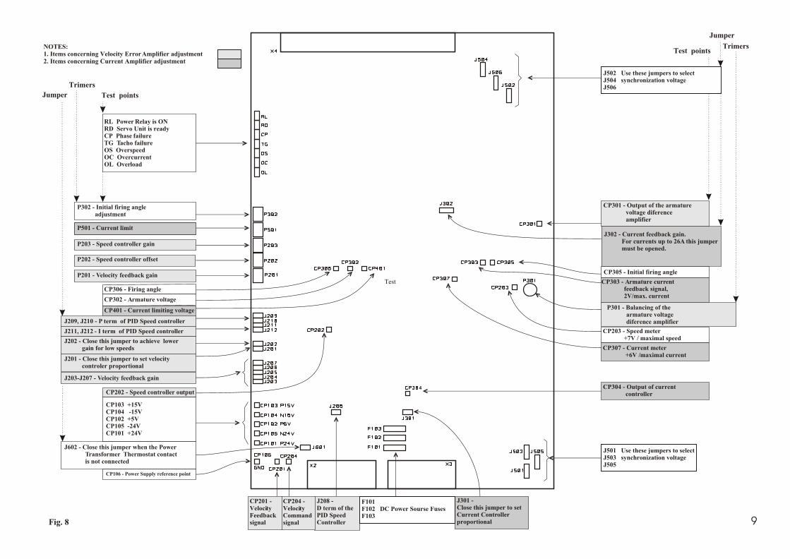
J302 - Current feedback gain. For currents up to 26A this jumper must be opened.
P301 - Balancing of the armature voltage diference amplifier
CP303 - Armature current feedback signal, 2V/max. current
P302 - Initial firing angle adjustment
RL Power Relay is ONRD Servo Unit is readyCP Phase failureTG Tacho failureOS OverspeedOC OvercurrentOL Overload
CP305 - Initial firing angle
CP306 - Firing angle
J209, J210 - P term of PID Speed controller
J211, J212 - I term of PID Speed controller
CP106 - Power Supply reference point
J501 Use these jumpers to selectJ503 synchronization voltageJ505
F101 F102 DC Power Sourse FusesF103
CP103 +15VCP104 -15VCP102 +5VCP105 -24VCP101 +24V
CP202 - Speed controller output
J203-J207 - Velocity feedback gain
J208 - D term of thePID Speed Controller
CP204 -VelocityCommandsignal
CP201 -VelocityFeedbacksignal
CP304 - Output of current controller
J301 - Close this jumper to setCurrent Controllerproportional
J201 - Close this jumper to set velocity controler proportional
J202 - Close this jumper to achieve lower gain for low speeds
CP203 - Speed meter +7V / maximal speed
CP307 - Current meter +6V /maximal current
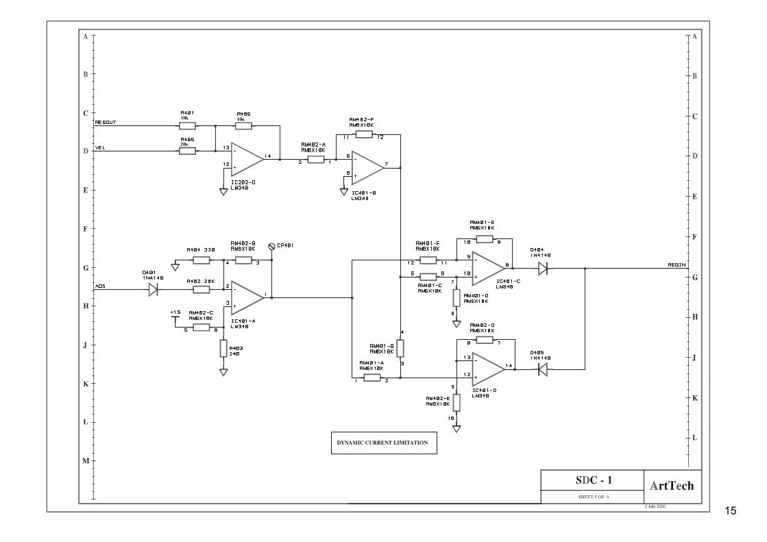
CP401 - Current limiting voltage
J502 Use these jumpers to selectJ504 synchronization voltageJ506
CP302 - Armature voltage
J602 - Close this jumper when the Power Transformer Thermostat contact is not connected
P501 - Current limit
4
CP301 - Output of the armature voltage diference amplifier
NOTES:1. Items concerning Velocity Error Amplifier adjustment2. Items concerning Current Amplifier adjustment
Jumper
Test
Test pointsTrimers
P203 - Speed controller gain
P202 - Speed controller offset
P201 - Velocity feedback gain
P501 - Current limit
J209, J210 - P term of PID Speed controller
Jumper Test points
Trimers

10
6. Adjustment of DC Servo Unit. 6.1. Items available without removing of the front panel. 6.2. Location of the variable resistors, jumpers and test points. 7. Installation of DC servo unit. 7.1. Installation conditions. The servo drive modules are intended for installation in metal cabinets. The ventilation system of the cabinet must ensure vertical air circulation through thyristor sections of the drive. 7.2. Outer dimensions - Fig.9.
A
A1
D
F
BE
C
Type A mm
B mm
C mm
D mm
E mm
F mm
SDC1-5.4 - SDC1-34.3
90
345
190
65
327
Φ 9
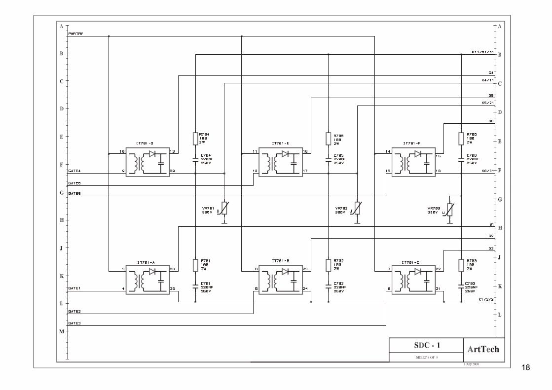
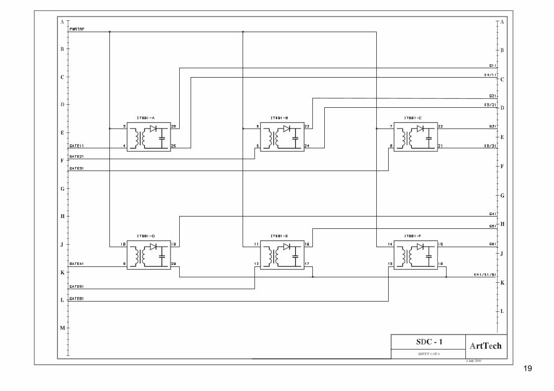
Fig. 10. Location of the thyristors. 1 2 3 4 5 6 7 8
N X L X M X N E S1 E S2 A 1 A 2X 5
X 4
+24
V
+ 24VGND XL XM XN ES2 A1 A2
G41 G11 G51 G21 G61 G31
G4 G1 G5 G2 G6 G3
ES2
+15
V
-15V UC
S
G1
G2
G3
G4
G5
G6
G11
G21
G31
G41
G51
G61
RLB
UF
GN
D
GN
D
RLS
PL
RLS
PL
K1/
2/3
K1/
2/3
K1/
2/3
K1/ 2/ 3
A2
A2
A2
XL
XM
XN
A1
A1
UCS
+ 15V
-15V
A1
K4/
11
K5/
21
K6/
31
K4/
11
K5/
21
K6/
31
K41
/51/
61
K41
/51/
61
K41
/51/
61
K41/ 51/ 61
RLBU F
86

11

12

13

14
36
J302
R32215
15
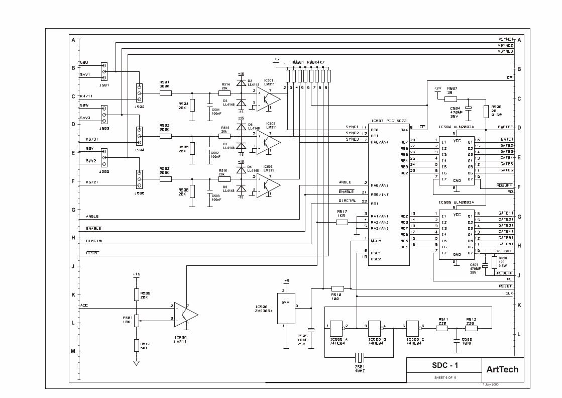
SHEET 6 OF 9
SDC - 1ArtTech
1 July 2000
A
B
C
D
E
F
G
H
J
K
L
M
A
B
C
D
E
F
G
H
K
L
J
RLLIGHT
R5181000.5WC507
470MF35V
IC501LM311
IC502LM311
IC503LM311
C503100nF
C502100nF
C501100nF
R51420k
R51520k
R51620k
+15
+15
+15
-15
-15
-15
D2LL4148
D3LL4148
D7LL4148
D6LL4148
D4LL4148
D5LL4148
17
18
19

SHEET 10
SDC - 1 IR
1 July 2000