Embed Size (px)
Citation preview

The Auckland Code of Practice for Land Development and Subdivision Water and Wastewater Code of Practice for Land Development and Subdivision Chapter 6: Water


Ver.2.23 This is an electronic ESF document that is uncontrolled when copied or printed Page 3 of 60
Based on Section 6 of NZS 4404: 2010 this document is part of the Auckland Code of
Practice for Land Development and Subdivision.
Chapter 6 – WATER
Document No. COP-01
Revision Description Released By Date
Draft 1.0 Initial document for internal consultation J Hodges 11/02/2011
Draft 2.2 Amended from feedback for external consultation J Hodges 12/04/2011
1.0 Amended after external consultation M Lind 15/06/2011
1.1 General re-formatting for website release M Lind 30/06/2011
1.2 Text expanded, errors corrected, more linked docs M Lind 06/12/2011
1.3 Text and linked docs updated, more linked docs M Lind 16/11/2012
1.4 Detailed updates to specifications and drawings J de Villiers 08/12/2014
1.5 Amended drawings and content Chief Executive 28/05/2015
2 Contents updated, specifically network hydraulic design parameters. Document format and leading section to water chapter replaced to accommodate Auckland Council chapter changes
J de Villiers 05/12/2017
2.1 Minor updates following public consultation. J de Villiers 27/07/2018
2.2 Minor updates. J de Villiers 01/11/2019
2.3 Drafted updates for public feedback J de Villiers 7/04/2021
The latest version of this standard takes effect on the date of release on all new work and supersedes all prior
versions or formats of this document.
Where design work has been completed or where construction work commenced, immediate adoption may be
delayed unless the change is required within a timeframe provided by legislation, or is an immediate health and
safety concern. Under these circumstances Watercare will review any work in progress and provide specific
notice for adoption.

Ver.2.23 This is an electronic ESF document that is uncontrolled when copied or printed Page 4 of 60
Summary of changes
Version Section Description of revision
2 Entire document Formatting and font
Introduction (section 1)
Foreword and introduction reworded. Sections numbered and rearranged.
Legislative -, standards – and other document reference have been updated. Referenced standards moved to section 3.
Deleted “Document hierarchy” diagram
Deleted “Water supply mains” process flowchart
Chapter 1 Removed. Referred to Auckland Code of Practice for Land development and Subdivision that now includes Chapter 1. Referenced made in section 3.
Chapter 8 Removed. Referred to Auckland Code of Practice for Land development and Subdivision that now includes Chapter 1. Referenced made in section 3.
2 New section describing relationship of Watercare standards and how this code of practice fits into the overall set.
3 Updated referenced standards and documents
4 Reproduction of deliverables that is removed from the previous version of Chapter 1 – this section identifies Watercare’s specific requirements to allow engineering plan evaluation.
6.1 Reworded to clarify document exclusions
6.2.2 Reworded with updated reference
6.3.3A Additional data and definition provided for contaminate free classification of works over water supply infrastructure
6.3.5.3 Previously referred occupancy reference to wastewater chapter now included in text. Lowered compounding peaking factors based on measured data.
6.3.5.6 Thresholds included design rates for where none was previously provided. Lowered average daily demand per person.
6.3.6.2 Deleted appendix H. Expanded on backflow prevention requirement in accordance with the Building Act and Water Bylaw
6.3.8.1 New image for typical services layout cross section
6.3.8.5 Reworded to provide for security of supply
6.3.8.6 Pipe may not be installed in tree root zones
6.3.8.7 Reworded. The design of shared service trench shall consider the pipe structural impact and minimum clearances
6.3.9.1 Updated service clearances requirements
6.3.12.2 Included base isolation options for closely located structures
6.3.12.6 Updated geotechnical references. Section 6.7 deleted
6.3.12.9 Updated reference to trenchless technologies
6.3.12.10.1 Amended acceptable pipe depths for pipe in the berm to include front
Ver.2.23 This is an electronic ESF document that is uncontrolled when copied or printed Page 5 of 60
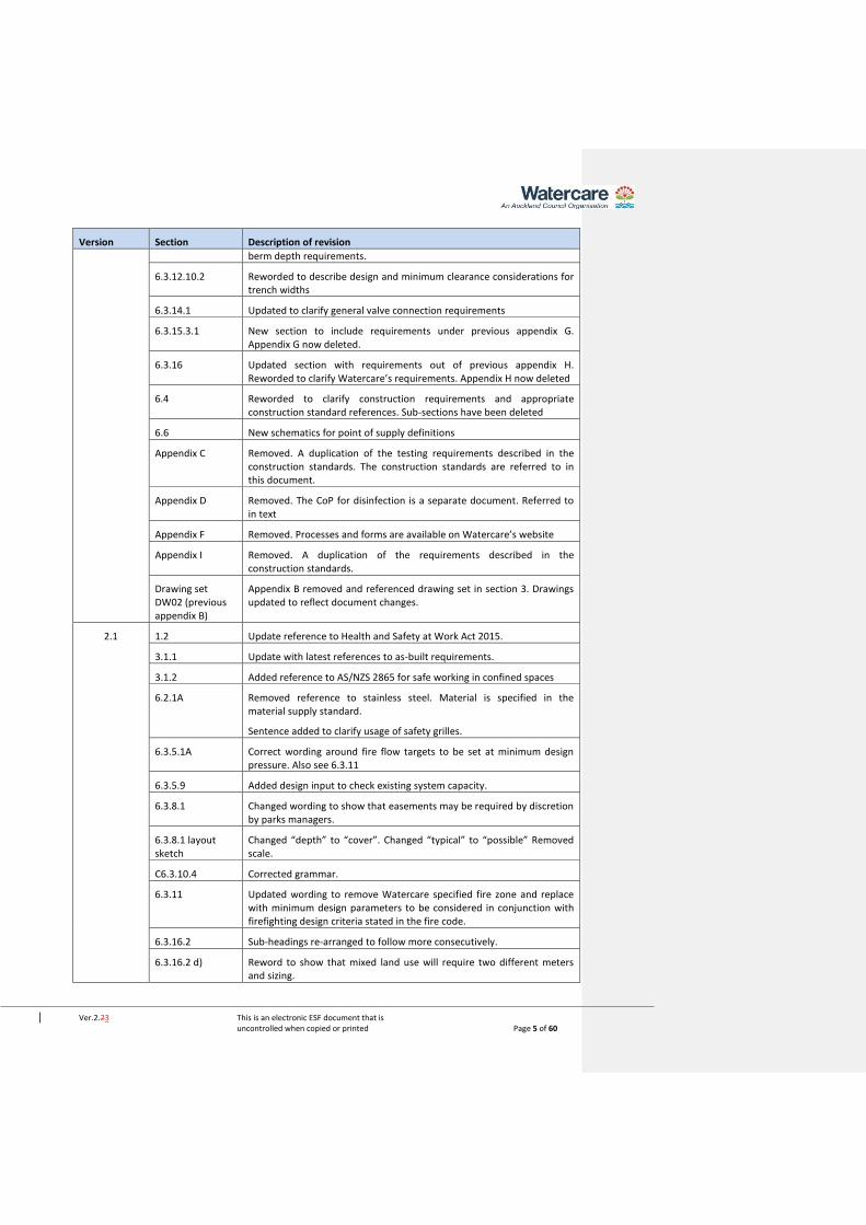
Version Section Description of revision
berm depth requirements.
6.3.12.10.2 Reworded to describe design and minimum clearance considerations for trench widths
6.3.14.1 Updated to clarify general valve connection requirements
6.3.15.3.1 New section to include requirements under previous appendix G. Appendix G now deleted.
6.3.16 Updated section with requirements out of previous appendix H. Reworded to clarify Watercare’s requirements. Appendix H now deleted
6.4 Reworded to clarify construction requirements and appropriate construction standard references. Sub-sections have been deleted
6.6 New schematics for point of supply definitions
Appendix C Removed. A duplication of the testing requirements described in the construction standards. The construction standards are referred to in this document.
Appendix D Removed. The CoP for disinfection is a separate document. Referred to in text
Appendix F Removed. Processes and forms are available on Watercare’s website
Appendix I Removed. A duplication of the requirements described in the construction standards.
Drawing set DW02 (previous appendix B)
Appendix B removed and referenced drawing set in section 3. Drawings updated to reflect document changes.
2.1 1.2 Update reference to Health and Safety at Work Act 2015.
3.1.1 Update with latest references to as-built requirements.
3.1.2 Added reference to AS/NZS 2865 for safe working in confined spaces
6.2.1A Removed reference to stainless steel. Material is specified in the material supply standard.
Sentence added to clarify usage of safety grilles.
6.3.5.1A Correct wording around fire flow targets to be set at minimum design pressure. Also see 6.3.11
6.3.5.9 Added design input to check existing system capacity.
6.3.8.1 Changed wording to show that easements may be required by discretion by parks managers.
6.3.8.1 layout sketch
Changed “depth” to “cover”. Changed “typical” to “possible” Removed scale.
C6.3.10.4 Corrected grammar.
6.3.11 Updated wording to remove Watercare specified fire zone and replace with minimum design parameters to be considered in conjunction with firefighting design criteria stated in the fire code.
6.3.16.2 Sub-headings re-arranged to follow more consecutively.
6.3.16.2 d) Reword to show that mixed land use will require two different meters and sizing.

Ver.2.23 This is an electronic ESF document that is uncontrolled when copied or printed Page 6 of 60
Version Section Description of revision
6.3.16.2.1 e) Clarification on acceptable connection isolation valves.
2.2 4 Added section 4.1 and 4.2 on climate change and carbon footprint considerations as part of design deliverables
6.3.5.6 Sentence added to limit validity period of the capacity assessment.
Table 6.1.c Clarification on floor area assessment added to notes
6.3.16.2.4 Correct drawing references
2.3 6.3.6.3 Water age – introducing additional measures for improving water quality during development of subdivisions
6.3.12.3 Added design considerations for trench design and location
6.3.16.2 Added additional connection options for larger development lots
C 6.3.16.2 Updated not to reflect individual meter reading service

Ver.2.23 This is an electronic ESF document that is uncontrolled when copied or printed Page 7 of 60
Foreword
This code of practice (CoP) has been developed to guide and govern subdivision, development and re-
development of water local network areas. It is applicable within the territory of the Auckland Council and
parts of Waikato, where these utility services are provided by, or are to be vested in, or connected to assets
owned by Watercare Services Limited (Watercare).
The code of practice is based on NZS 4404:2010 Land Development and Subdivision Infrastructure. Various
parts have been reproduced pursuant to Licence 000805 granted to Watercare by Standards New Zealand.
The purpose of NZS 4404 is to deliver good urban design and infrastructure of good quality that is consistent
with industry best practices.
NZS 4404 is a national standard developed to accommodate local variations to suit different conditions and
circumstances. AccordinglyAccordingly, there are numerous inserts by Watercare to deliver local
requirements, many of which have been embedded in the local industry for some time.
The clause numbering of the original standard has been retained for section 5 to facilitate cross-referencing.
To assist practitioners used to, or wishing to draw comparison to NZS 4404, altered text or additions are
presented in Italic font. Deleted text or sections are not shown.
Sections highlighted in grey are intended as comments and guidance notes. These clauses are not mandatory.

Ver.2.23 This is an electronic ESF document that is uncontrolled when copied or printed Page 8 of 60
Table of contents
FOREWORD ..................................................................................................................................................... 7
DEFINITIONS .................................................................................................................................................. 12
ABBREVIATIONS ............................................................................................................................................ 13
1. INTRODUCTION ..................................................................................................................................... 15
1.1 OUTCOME STATEMENT ........................................................................................................................ 15
1.2 NEW ZEALAND LEGISLATION ................................................................................................................. 15
1.3 WEBSITES ........................................................................................................................................ 16
1.4 ‘MUST’ VERSUS ‘SHALL’ VERSUS ‘WILL’ .................................................................................................. 16
1.5 REVIEW OF STANDARDS ....................................................................................................................... 16
1.5.1 Watercare’s engineering standards framework ............................................................................. 16
1.5.2 Governance of standards ................................................................................................................ 16
2. STANDARD DOCUMENTS OVERVIEW..................................................................................................... 17
2.1 RELATIONSHIP OF WATERCARE STANDARDS ............................................................................................. 17
2.1.1 Design standards............................................................................................................................. 17
2.1.2 Design drawings .............................................................................................................................. 17
2.1.3 Asset and material standards ......................................................................................................... 17
2.1.4 Construction standards ................................................................................................................... 17
2.1.5 Project specific specification ........................................................................................................... 17
2.2 DESIGN BUILD PROJECTS ...................................................................................................................... 17
3. REFERENCED STANDARDS ..................................................................................................................... 18
3.1 STANDARDS LIST ................................................................................................................................ 18
3.1.1 Watercare standards ...................................................................................................................... 18
3.1.2 National and international standards ............................................................................................. 18
3.1.3 Other publications .......................................................................................................................... 18
4. DESIGN DELIVERABLES .......................................................................................................................... 19
4.1 CLIMATE CHANGE ............................................................................................................................... 20
4.2 CARBON FOOTPRINT REDUCTION ........................................................................................................... 20
5. [INTENTIONALLY BLANK] ....................................................................................................................... 20
6. WATER .................................................................................................................................................. 21
6.1 SCOPE ............................................................................................................................................. 21
6.2 GENERAL REQUIREMENTS .................................................................................................................... 21
6.2.1 Objectives ....................................................................................................................................... 21
6.2.1A Safety of people .......................................................................................................................... 22

Ver.2.23 This is an electronic ESF document that is uncontrolled when copied or printed Page 9 of 60
6.2.2 Referenced documents and relevant guidelines ............................................................................ 22
6.3 DESIGN............................................................................................................................................ 22
6.3.1 Design life ....................................................................................................................................... 22
6.3.2 Structure plan ................................................................................................................................. 22
6.3.3 Future development ....................................................................................................................... 22
6.3.3A Contaminated sites ..................................................................................................................... 22
6.3.4 System design ................................................................................................................................. 23
6.3.5 Design criteria ................................................................................................................................. 24
6.3.5.1 Hydraulic design ..................................................................................................................................... 24
6.3.5.1A Hydrant flow tests .................................................................................................................................. 24
6.3.5.2 Network analysis .................................................................................................................................... 24
6.3.5.3 Peak flows .............................................................................................................................................. 25
6.3.5.4 Head losses ............................................................................................................................................ 25
6.3.5.4.1 Hydraulic roughness values ................................................................................................................... 25
6.3.5.5 Minimum flows ...................................................................................................................................... 26
6.3.5.6 Minimum water demand ....................................................................................................................... 26
6.3.5.7 Sizing of mains ....................................................................................................................................... 29
6.3.5.8 Water district zones ............................................................................................................................... 29
6.3.5.9 Watermain hydraulic design input and output ...................................................................................... 30
6.3.5.10 Design pressure ...................................................................................................................................... 30
6.3.6 Water quality .................................................................................................................................. 30
6.3.6.1 Materials ................................................................................................................................................ 31
6.3.6.2 Prevention of backflow .......................................................................................................................... 31
6.3.6.3 Water age .............................................................................................................................................. 32
6.3.7 Flow velocities ................................................................................................................................ 32
6.3.7.1 Surge analysis ......................................................................................................................................... 33
6.3.8 System layout ................................................................................................................................. 34
6.3.8.1 General .................................................................................................................................................. 34
6.3.8.2 Principal and rider mains layout ............................................................................................................ 35
6.3.8.3 Mains layout .......................................................................................................................................... 35
6.3.8.4 Watermains in private property ............................................................................................................ 35
6.3.8.5 Types of system configuration ............................................................................................................... 35
6.3.8.6 Watermains near trees .......................................................................................................................... 35
6.3.8.7 Shared trenching .................................................................................................................................... 35
6.3.8.8 Rider mains and duplicate principal mains ............................................................................................ 35
6.3.8.9 Crossings ................................................................................................................................................ 36
6.3.8.10 Crossings of waterways or reserves ....................................................................................................... 36

Ver.2.23 This is an electronic ESF document that is uncontrolled when copied or printed Page 10 of 60
6.3.8.11 Location marking of valves and hydrants ............................................................................................... 36
6.3.8.12 Location of watermains on bridges ........................................................................................................ 36
6.3.9 Clearances ....................................................................................................................................... 37
6.3.9.1 Clearance from underground services ................................................................................................... 37
6.3.9.2 Clearance from structures ..................................................................................................................... 38
6.3.9.3 Clearance from high voltage transmission facilities ............................................................................... 38
6.3.9.4 Deviation of mains around structures.................................................................................................... 39
6.3.10 Pipe selection ............................................................................................................................. 39
6.3.10.1 Standard pipe sizes ................................................................................................................................ 39
6.3.10.2 Minimum pipe sizes ............................................................................................................................... 39
6.3.10.3 Pipe PN class (pressure rating) ............................................................................................................... 39
6.3.10.3.1 Design pressure ................................................................................................................................. 39
6.3.10.4 Pipe materials ........................................................................................................................................ 40
6.3.11 Fire flow ...................................................................................................................................... 40
6.3.11.1 Fire protection services .......................................................................................................................... 40
6.3.12 Structural design ........................................................................................................................ 41
6.3.12.1 General .................................................................................................................................................. 41
6.3.12.2 Seismic design ........................................................................................................................................ 41
6.3.12.3 Structural consideration ........................................................................................................................ 41
6.3.12.4 Internal forces ........................................................................................................................................ 41
6.3.12.5 External forces ................................................................................................................................... 4241
6.3.12.6 Geotechnical investigations ................................................................................................................... 42
6.3.12.7 Pipe selection for special conditions ...................................................................................................... 42
6.3.12.8 Above-ground watermains .................................................................................................................... 42
6.3.12.9 Trenchless technology ........................................................................................................................... 42
6.3.12.10 Embedment ....................................................................................................................................... 43
6.3.12.11 Pipeline restraint ............................................................................................................................... 43
6.3.13 Reservoirs and pumping stations ............................................................................................... 44
6.3.14 Valves ......................................................................................................................................... 44
6.3.14.1 General .................................................................................................................................................. 44
6.3.14.2 Siting of valves ................................................................................................................................... 4544
6.3.14.3 Gate valves and sluice valves ................................................................................................................. 45
6.3.14.4 Butterfly valves ...................................................................................................................................... 47
6.3.14.5 Pressure reducing valves ........................................................................................................................ 47
6.3.14.6 Air valves ................................................................................................................................................ 47
6.3.14.7 Scours and pump-out branches ............................................................................................................. 48
6.3.15 Hydrants ..................................................................................................................................... 49

Ver.2.23 This is an electronic ESF document that is uncontrolled when copied or printed Page 11 of 60
6.3.15.1 General .................................................................................................................................................. 49
6.3.15.2 Hydrants for firefighting......................................................................................................................... 49
6.3.15.3 Hydrant installation ............................................................................................................................... 49
6.3.15.4 Hydrants for reticulation system operational requirements ................................................................. 50
6.3.15.5 Hydrants at ends of mains ..................................................................................................................... 50
6.3.16 Connections ................................................................................................................................ 50
6.3.16.1 Connection of new mains to existing mains .......................................................................................... 50
6.3.16.2 Property service connections ................................................................................................................. 51
6.3.17 Termination points ................................................................................................................. 5453
6.3.17.1 Permanent ends of watermains ......................................................................................................... 5554
6.3.17.2 Temporary ends of watermains ............................................................................................................. 55
6.4 APPROVAL OF PROPOSED INFRASTRUCTURE ............................................................................................. 55
6.4.1 Approval process ............................................................................................................................ 55
6.4.2 Information to be provided ............................................................................................................ 55
6.5 CONSTRUCTION ................................................................................................................................. 55
6.6 POINT OF SUPPLY – WATER ................................................................................................................. 57

Ver.2.23 This is an electronic ESF document that is uncontrolled when copied or printed Page 12 of 60
Definitions
Annual exceedance probability (AEP) The probability of exceedance of a given occurrence, generally a
storm, in a period of 1 year (1% AEP is equal to 1 in 100 year
storm).
Assets Water and wastewater infrastructure owned and operated by
Watercare.
Brownfield A land area that has existing or legacy infrastructure, or land that
has been contaminated.
Developer An individual or organisation having the financial responsibility for
the development project. Developer includes the owner.
Designer The developer’s professional advisor, appointed by the developer
to complete the investigation, design, contract administration,
construction supervision, and certification of the works on
completion.
Dwelling Any building or group of buildings, or part thereof used, or
intended to be used principally for residential purposes and
occupied, or intended to be occupied by not more than one
household.
Dwelling unit equivalent (DUE) A unit of water demand of 220 kilolitres per year on average, or,
where a wastewater meter is installed, a unit of wastewater
discharge of 209 kilolitres per year on average. The number of
DUE’s is based on the additional demand for water and/or
wastewater at the property and will be rounded to the nearest
whole number.
Greenfield A land area that has no prior infrastructure development and is not
contaminated.
Infill Development within a previously developed area.
Water local network The water local network covers the reticulated distribution system
from the water transmission systems to each property. Pipelines
are generally less than DN250.
Water transmission The water transmission system covers the bulk conveyance of
water to reservoir storage or to bulk supply points across the
Auckland region. Customers are not supplied directly from
transmission systems.
Peet valve A gate valve that is installed on a rider main.
Point of supply The ‘point of supply’ is the point where Watercare’s network
connects with a private network. At this point, the responsibility
for ownership and maintenance of assets and equipment transfers
from Watercare to the customer.

Ver.2.23 This is an electronic ESF document that is uncontrolled when copied or printed Page 13 of 60
Private connection Private connection is the pipe connection from the private
property up to the Watercare meter.
Principal main A watermain that is DN100 or greater. Fire hydrants may be
installed on a principal main.
Rider main A water supply main that is supplied from a principal watermain. A
rider main is smaller than the principal main, but not less than
DN50.
Service lead The lateral pipe connection up to the point of supply is installed in
public road reserve and is owned by Watercare. The service lead is
also commonly referred to as the “service connection” or “lateral
connection”.
Structure A piece of infrastructure (excluding pipework), that may be
constructed from various types of materials that includes
something built or arranged such as underground chambers or pits,
a building or building components such as foundations, piles or
retaining walls.
Sluice valve A gate valve that is installed on a principal main.
System (water/network reticulation) The interconnected hydrological engineered layout and hydraulic
components such as pipes, valves and pumps.
Toby valve A small gate valve installed on a service lead.
Abbreviations
AEP Annual exceedance probability
CBD Central business district
CCO Council controlled organisation
CoP Code of practice
CLS Concrete lined steel (pipe)
DN Nominal diameter
ESF Engineering standards framework
ha hectare
L/d Litres per day
L/p/d Litres per person per day
L/m²/d Litres per square metre area per day
L/s Litres per second

Ver.2.23 This is an electronic ESF document that is uncontrolled when copied or printed Page 14 of 60
HGL Hydraulic grade level
IQP Independent qualified person
m metre
m2 square metre (area)
mm millimetres
MPa megapascal
m/s metres per second
NB Nominal bore. The inside diameter of a pipe
PE Polyethylene
PF Peaking factor
PN Pressure nominal. Maximum rated operating pressure
Ver.2.23 This is an electronic ESF document that is uncontrolled when copied or printed Page 15 of 60
1. Introduction
This code of practice applies to the design of local network systems in greenfields (urban expansion), infill and
brownfield (urban renewal) redevelopment projects. These ventures must demonstrate compliance with the
requirements of this code of practice for design and Watercare’s material supply and construction standards
before being able to be connected to the Watercare local network system. This document is not an urban
design policy, or method of master planning.
Watercare is a Council Controlled Organisation (CCO) of the Auckland Council with specific legislative rights
and obligations set out in the Local Government (Auckland Council) Act 2009 No 32 and the Local Government
(Auckland Transitional Provisions) Act 2010 No 37. Watercare is responsible for the bulk and retail (local
network) water and wastewater services throughout the Auckland region. In the former Papakura District
Council, Veolia Water is under contract with Watercare to deliver local network services. Veolia Water applies
this code of practice.
The applicable legislation, this document and other Watercare standards, plans and by-laws are to ensure that:
• Water is used efficiently and wastage is minimised as best practicable
• Watercare’s and other publicly owned assets are not damaged and future access is not compromised
by the actions of third parties
• Infrastructure that is created, is of good quality, meets health requirements and minimises ongoing
maintenance costs
• Meets future demands on maintainability and access as infrastructure age and the natural
environment change
Developing, setting and monitoring subdivision and development standards for greenfield (urban expansion),
brownfield (urban renewal) or other development (e.g. intensification) is an important part of ensuring the
above requirements are met.
Sub-divisional, development and redevelopment proposals are approved and authorised by the Auckland
Council. Watercare’s contribution to this process is the examination and acceptance of the design,
construction and commissioning of elements of water and wastewater infrastructure, which will ultimately
become part of Watercare’s infrastructure. This includes works on private property where developments
proposing changed land use or intensification may result in a significant alteration to the local demand
pattern.
1.1 Outcome statement
This code of practice provides developers and their engineering professionals with the standard for design of
local network systems that is consistent across the Auckland region and encourages innovation whilst
maintaining basic requirements and sustainable development. This performance outcome requirement allows
Watercare to manage the infrastructure in an economical and safe manner over the life of the assets.
1.2 New Zealand legislation
The requirements of this Code of Practice (CoP) shall be read subject to the provisions of the latest versions
and amendments of the Auckland Unitary Plan and to any applicable statutes, regulations, bylaws, including
(but not limited to):
• Building Act 2004, Building Regulations, and New Zealand Building Code (NZBC) 1992
• Civil Defence Emergency Management Act 2002
• Conservation Act 1987

Ver.2.23 This is an electronic ESF document that is uncontrolled when copied or printed Page 16 of 60
• Government Roading Powers Act 1989
• Health and Safety at Work act 2015
• Health (Drinking Water) Amendment Act 2007
• Historic Places Act 1993
• Infrastructure (Amendments Relating to Utilities Access) Act 2010
• Land Transfer Act 1952
• Local Government Act 1974 and Local Government Act 2002, and related by-laws
• Reserves Act 1977
• Resource Management Act 1991, including all applicable regional and territorial planning documents
• Local Government (Auckland Council) Act 2009
• Local Government (Auckland Transitional Provisions) Act 2010
• Utilities Access Act 2010, National Code of Practice for Utility Operators’ Access to Transport
Corridors
1.3 Websites
• Auckland Council www.aucklandcouncil.govt.nz
• Auckland Design Manual www.aucklanddesignmanual.co.nz
• Auckland Transport https://at.govt.nz/
• Ministry for the Environment http://www.mfe.govt.nz
• Heritage New Zealand http://www.historic.org.nz
• New Zealand Legislation http://www.legislation.govt.nz
• New Zealand Transport Agency http://www.nzta.govt.nz/
1.4 ‘Must’ versus ‘Shall’ versus ‘Will’
Where the verbs must, shall and will (or its past tense forms) are used, they describe a requirement for compliance with the statement in which it is used.
‘Shall’ and ‘must’ expresses a mandatory condition or action. ‘Will’ is used to prescribe a performance outcome or intent.
1.5 Review of standards
Section 1.5 is provided for information only.
Watercare updates its standards and codes of practices from time to time. Users of this document should ensure that the latest published version is used. Suggestions for improvement of this standard are welcome. They should be sent to: Principal Engineer - Standards, Watercare Services Limited, Private Bag 92521, Wellesley Street, Auckland 1141.
Alternatively place feedback electronically at www.Watercare.co.nz
1.5.1 Watercare’s engineering standards framework
The Watercare standards are provided in the online engineering standards framework (ESF). The system provides guidance to the end user to find the applicable standards for the operational area in which design, construction or maintenance is performed. The system ensures that the latest versions of standards are available. The standards are uncontrolled when copied or printed.
1.5.2 Governance of standards
Changes to standards are made under a governance structure to evaluate any change or improvements against factors such as Health and Safety, legislative compliance, standards, best practice and asset reliability.

Ver.2.23 This is an electronic ESF document that is uncontrolled when copied or printed Page 17 of 60
2. Standard documents overview
2.1 Relationship of Watercare standards
Watercare standards comprise of codes of practices, design standards, standard design drawings, construction standards, and asset and material standards.
The Watercare standards are requirements additional to nominated national standards, international standards and industry best practice to meet, and in some cases exceed legislative requirements, to accomplish long term operability and good asset management practices to benefit our customers. The interface of these standards with each other and the project specifications are as follows:
2.1.1 Design standards
Design standards set a level of design for particular types of infrastructure based on operational area and associated risk. The design standards provide the minimum criteria for establishing baseline standard design drawings, interface design between standardised components, establishing the correct sizing of components to complement the baseline parameters of standard drawings and the basis for developing bespoke designs. This document falls within the design standards category and must be read with the relevant drawings and standards for asset capture, materials supply and construction.
2.1.2 Design drawings
The standard design drawings support the requirements of the design standard. Minimum and maximum criteria are set, and specific standard details are shown.
2.1.3 Asset and material standards
The asset standards describe the requirements for asset creation, asset numbering, asset capture, production of manuals and operational documentation. Material standards describe the minimum compliance requirements of materials supplied for asset acceptance. Often selected materials will have limitations of use and requirements specific to the operating environment and infrastructure classification.
2.1.4 Construction standards
Construction standards prescribe the methods and requirements for workmanship to be employed when constructing works in accordance with the design requirements, standard drawings and bespoke designs. To achieve the best outcome the construction requirements focusses on proven methods and best practice to ensure quality is maintained to achieve the design life of infrastructure, maintainability, health and safety and environmental requirements are met. Where construction standards are used or referred to in contracts they form part of the specification of the contract.
2.1.5 Project specific specification
These specifications identify site/project specific requirements that are not covered by the normative construction standards or standard design drawings identified during specific design.
2.2 Design build projects
Design build projects shall follow the minimum requirements set out in the standard documents for design and construction.

Ver.2.23 This is an electronic ESF document that is uncontrolled when copied or printed Page 18 of 60
3. Referenced standards
3.1 Standards list
This code of practice must be read in conjunction with the Watercare, national and international standards listed below and the relevant chapters of the Auckland Code of Practice for Land Development. Where conflict or ambiguity exists, this standard shall take precedence. Where there is conflict between referenced standards, the higher level of standard shall take precedence.
3.1.1 Watercare standards
CG – General civil construction standard ME – General mechanical construction standard MS – Material supply standard 7363 – Watercare CAD manual AI – Data and asset information standard DP-15 – Local network water pump stations DW06 - Access structure drawings for water infrastructure DW07 - Access structures general drawings for public and non-public areas DW02 - Code of Practice for Land Development and Subdivision –Water drawing set DW04 - Water pump station drawings for networks DP-09 Electrical design standard EC - General electrical construction standards
COP-03 Code of Practice for commissioning COP-04 Code of Practice for disinfection of water systems
3.1.2 National and international standards NZS 4404 Land development and subdivision infrastructure SNZ HB 44 Subdivision for people and the environment NZS 1170 Structural design actions Part 5 Earthquake actions – New Zealand Part 5 Supp 1 Earthquake actions – New Zealand – Commentary NZS 4219 Seismic performance of engineering systems in buildings NZS/AS 1657 Fixed platforms, walkways, stairways and ladders. Design, construction and installation SNZ PAS 4509 New Zealand Fire Service fire fighting water supplies code of practice AS/NZS 2041 Buried corrugated metal structures Part 1 Design Methods Part 6 Bolted plate structures AS/NZS 2566 Buried flexible pipelines Part 1 Structural design Part 1 Supp 1 Structural design – Commentary AS/NZS 3725 Design for installation of buried concrete pipes AS/NZS 2865 Safe working in confined space AS/NZS 3500 Plumbing and drainage Part2 Sanitary plumbing and drainage AS 2200 Design charts for water supply and sewerage
3.1.3 Other publications
Ministry for the Environment. New Zealand urban design protocol. Wellington: Ministry for the
Environment, 2005.

Ver.2.23 This is an electronic ESF document that is uncontrolled when copied or printed Page 19 of 60
Ministry for the Environment. Coastal hazards and climate change – A guidance manual for local
government in New Zealand. Wellington: Ministry for the Environment, 2008.
Preparing for climate change – A guide for local government in New Zealand. Wellington: Ministry for
the Environment, 2008.
Preparing for coastal change – A guide for local government in New Zealand. Wellington: Ministry for
the Environment, 2009.
Preparing for future flooding – A guide for local government in New Zealand. Wellington: Ministry for
the Environment, 2010.
Ministry of Health. Drinking-water standards for New Zealand 2005 (Revised 2008). Wellington:
Ministry of Health, 2008.
Seismic Guidelines for Water Pipelines, American Lifelines Alliance, 2005
Guidelines for Seismic Design of Buried Pipelines, NICEE, 2007
Underground Utilities – Seismic assessment and design guidelines, Water New Zealand
NZTA M/07 Specification for roadmarking paints
Health and Safety in Design Minimum standard, Watercare, 2017
4. Design deliverables
The design shall be delivered by a person with evaluated competency, refer to the Watercare compliance
statement policy for acceptable levels of qualification and competency registration. The following
comprehensive documents shall be provided to Watercare for evaluation of the design:
a) Geotechnical report on the suitability of the land for subdivision
b) Basis of design report describing options and selection of design
c) Final design report that includes:
• Site information such as location, layout, contours and soil contamination test results.
• Impact assessment on adjacent properties and services
• Value engineering that includes material selection, constructability analysis, simplification,
innovation and life-cycle costing
• Assumptions and non-compliance - identifying alternative options to meet performance
requirements
• Detailed calculations
• Drawings showing location, detailed long sections, pipe grades and sectional details
• Site specific specification for construction
• Nominated minimum levels of construction supervision
d) Risk analysis
e) Functional descriptions (process and pump stations)
f) O&M manual
g) New assets register
h) Project execution plan that includes the engineering construction plan/approach and Watercare’s
connection requirements
i) Design compliance statement – See Watercare compliance statement policy

Ver.2.23 This is an electronic ESF document that is uncontrolled when copied or printed Page 20 of 60
4.1 Climate change
To address the impact of climate change on new infrastructure, the design shall demonstrate the measures
taken to address the impact by:
• The considerations of various scenarios to determine the key financial, operational and
environmental performance indicators
• Compare adaptation measures and allow prioritisation
• The location of infrastructure and the impact of flooding on infiltration and overflows,
• Addressing water level rise and possible need for asset relocation, floatation of assets, saltwater
intrusion and submerged outfalls
• Mitigating energy costs for increased pumping
4.2 Carbon footprint reduction
The infrastructure owned and operated by Watercare has a large influence on new projects, renewals and
ongoing maintenance. Watercare policy is to aim for net zero emissions by 2050 and reducing emissions by
40% by the year 2025. To support this policy new infrastructure should demonstrate opportunities for:
• System selection and layout
• Low carbon infrastructure delivery in construction
• Product selection
• Energy efficiencies
• Carbon removals
5. [Intentionally blank]
Section 5 is intentionally left blank so that the numbering will follow the original format of NZS4404. The
wastewater chapter is a separate document, document number COP-02.

Ver.2.23 This is an electronic ESF document that is uncontrolled when copied or printed Page 21 of 60
Co
nte
nt
fro
m t
he
Sta
nd
ard
NZ
S 4
40
4:2
01
0 L
an
d d
eve
lop
me
nt
an
d s
ub
div
isio
n in
fra
str
uctu
re h
as b
ee
n r
ep
rod
uce
d f
or
use
in
th
e W
ate
rca
re E
ng
ine
eri
ng
sta
nd
ard
s F
ram
ew
ork
with
pe
rmis
sio
n f
orm
Sta
nd
ard
s N
ew
Ze
ala
nd
un
de
r L
ice
nce
00
08
05.
Am
en
de
d t
ext
is s
ho
wn
in
Ita
lic f
on
t.
6. WATER
6.1 Scope
This section sets out requirements for the design and construction of drinking water supply systems. It covers
the design of the local network system.
The scope of water networks under this Code of Practice (CoP) is limited to pipe sizes of up to DN250.
If the intended water system exceeds the above limitations, notice shall be provided to Watercare to identify
appropriate standard details from the Watercare transmission standard to be adopted. These can be viewed on
Watercare’s ESF. This code of practice excludes design requirements for treatment facilities, reservoirs or pump
stations.
Proposals involving third pipe systems for non-potable supply must be discussed with Watercare as early as
possible as it could impact on both water and wastewater networks.
6.2 General requirements
6.2.1 Objectives
The objectives are to ensure that the water reticulation system is functional, the required quality and quantity
of water is supplied to all customers within Watercare’s water supply area.
The design shall ensure an acceptable water supply for each property including fire flows, by providing either:
(a) A watermain allowing an appropriate point of supply to each property; or
(b) A service connection from the main for each property. The water meter for each property must be
installed by Watercare. Application for new water meters can be made to Watercare’s Connections
Team, [email protected].
In principle the water system shall provide:
(c) Compliance with Watercare’s policies, customer contract and design standards;
(d) The hydraulic adequacy of the system;
(e) The ability of the water system to maintain acceptable water quality;
(f) The structural strength of water system components to resist applied loads;
(g) The requirements of SNZ PAS 4509;
(h) Compliance with environmental requirements;
(i) Consideration to the environmental and community effects of the works;
(j) The ‘fit-for-purpose’ service life for the system as specified in this CoP;
(k) Optimising the ‘whole-of-life’ cost;
(l) Each component’s resistance to internal and external corrosion or degradation;
(m) Compatibility with Watercare’s site specific requirements for service delivery and maintenance;
(n) Compatibility with Watercare’s long term management strategy and plan (confirmation to be sought
from Watercare) for the overall supply zone
(o) Compliance with Health and Safety requirements in design, construction and disinfection stages of a
project; and
(p) Consideration to any environmental changes through the life of the asset in terms of sustainability,
asset renewal, future access and levels of service.

Ver.2.23 This is an electronic ESF document that is uncontrolled when copied or printed Page 22 of 60
Co
nte
nt
fro
m t
he
Sta
nd
ard
NZ
S 4
40
4:2
01
0 L
an
d d
eve
lop
me
nt
an
d s
ub
div
isio
n in
fra
str
uctu
re h
as b
ee
n r
ep
rod
uce
d f
or
use
in
th
e W
ate
rca
re E
ng
ine
eri
ng
sta
nd
ard
s F
ram
ew
ork
with
pe
rmis
sio
n f
orm
Sta
nd
ard
s N
ew
Ze
ala
nd
un
de
r L
ice
nce
00
08
05.
Am
en
de
d t
ext
is s
ho
wn
in
Ita
lic f
on
t.
6.2.1A Safety of people
Chamber entries shall be fitted with an accepted safety grille supported by the chamber lid frame. The grille
does not require to be locked in place separately. Other access points to Watercare’s network may also require
a form of fall restraint. Chambers exclude valve boxes and the like where a person cannot fall into the chamber.
6.2.2 Referenced documents and relevant guidelines
Water designs shall incorporate all the special requirements of Watercare and shall be in accordance with the
appropriate Standards, codes, technical policies and guidelines including those set out in Referenced
Documents. Refer to section 3.
6.3 Design
6.3.1 Design life
All water supply systems shall be designed and constructed for an asset life of at least 100 years. Some
components such as pumps, metering, control valves, and control equipment may require earlier renovation
or replacement. Watercare lists a number of accepted and standardised materials. The use of components not
listed on the material supply standards requires specific approval from Watercare prior to their use.
6.3.2 Structure plan
Auckland Council may live zone land or facilitiatefacilitate a structure plan setting out certain information to be
used in design, such as population to be served, flows, sizing, upstream controls, roading, recommended pipe
route layout, or particular requirements of Watercare and the Auckland Council. Where a structure plan is not
provided, the designer shall determine this information by investigation using this CoP, engineering principles
and by discussion with Watercare as necessary.
6.3.3 Future development
Where further subdivision, adjacent to the one under consideration, is provided for in the Auckland Unitary
Plan, the water supply infrastructure must be designed to cater for future development.
6.3.3A Contaminated sites
Contaminated sites should be avoided. Where a contaminated site has been confirmed, written approval to
proceed shall be obtained from the Auckland Council and Watercare. The following issues shall be addressed in
the request for approval:
• The nature of the contamination;
• Compliance with statutory requirements;
• Options to de-contaminate the area;
• Selection of appropriate pipe materials, coatings and jointing techniques to maintain water quality;
• Selection of pipeline materials to achieve the required life expectancy of the watermain;
• Safety of construction and maintenance personnel; and
• Special watermain maintenance considerations.
Watermains and connections in the immediate vicinity of petrol stations shall not be constructed of PE or PVC
material. Ductile Iron (and copper for connections) or an alternative material approved by Watercare shall be
used.
Any contaminants in the soil, including topsoil on the site, shall be at the lesser levels of the health-based or
environmental related protection values as described below:

Ver.2.23 This is an electronic ESF document that is uncontrolled when copied or printed Page 23 of 60
Co
nte
nt
fro
m t
he
Sta
nd
ard
NZ
S 4
40
4:2
01
0 L
an
d d
eve
lop
me
nt
an
d s
ub
div
isio
n in
fra
str
uctu
re h
as b
ee
n r
ep
rod
uce
d f
or
use
in
th
e W
ate
rca
re E
ng
ine
eri
ng
sta
nd
ard
s F
ram
ew
ork
with
pe
rmis
sio
n f
orm
Sta
nd
ard
s N
ew
Ze
ala
nd
un
de
r L
ice
nce
00
08
05.
Am
en
de
d t
ext
is s
ho
wn
in
Ita
lic f
on
t.
• Health based protection values:
NES Soil contaminant standards (SCS) for residential land use (no produce, if applicable) as derived in
accordance with Ministry for the Environment Methodology for Deriving Standards for Contaminants
in Soil to Protect Human Health (Chapter 7). In the absence of a derived NES Soil SCS, then a
standard following the hierarchy outlined in the Ministry for the Environment, Contaminated Land
Management Guidelines No 2 shall be adopted.
• Environmental related protection values:
Auckland Council Air Land and Water (ALW) Plan criteria for discharges as described in Rules 5.5.41.
• No asbestos containing material or volatile organic compounds in site soils.
No free (or separate) phase liquid contaminants and groundwater contaminant concentrations, with the
exception of volatile organic compounds, which must be below the Australian and New Zealand Guidelines for
Fresh and Marine Water Quality at the level of protection for 80% of freshwater species. Concentrations of
volatile organic compounds shall be below typical laboratory screening detection limits (0.5 mg/L or lower).
The following table sets out the acceptance criteria for contaminant free sites:
Contaminant Acceptance level (mg/kg)
Arsenic <24
Cadmium <7.5
Chromium <400
Copper <325
Lead <250
Mercury <0.75
Nickel <105 1
Zinc <200 1
Benzo(a)pyrene
equivalent
<2.15
Pyrene <1
ΣDDT <0.7
VOCs Below laboratory detection
limit
1 Can use upper limit background concentration in Auckland region (i.e. 320 for Nickel and 1160 for Zinc) if the soil is
volcanic source
A site investigation including soil sampling and testing must be undertaken and a report submitted to
Watercare in accordance with the requirements of the Ministry for the Environment, 2011, Contaminated Land
Management Guidelines No. 1 - Reporting on Contaminated Sites in New Zealand. Testing shall be conducted
by a NATA/IANZ accredited laboratory.
Soil testing data is required at the position for the proposed water infrastructure. Watercare reserves the right
to request additional soil testing at the cost of the developer where the data supplied is considered inadequate
or not representative of the site.
6.3.4 System design
Watermains shall be designed with sufficient capacity to cater for all existing and predicted development
within the area to be served and to meet the requirements of SNZ PAS 4509.

Ver.2.23 This is an electronic ESF document that is uncontrolled when copied or printed Page 24 of 60
Co
nte
nt
fro
m t
he
Sta
nd
ard
NZ
S 4
40
4:2
01
0 L
an
d d
eve
lop
me
nt
an
d s
ub
div
isio
n in
fra
str
uctu
re h
as b
ee
n r
ep
rod
uce
d f
or
use
in
th
e W
ate
rca
re E
ng
ine
eri
ng
sta
nd
ard
s F
ram
ew
ork
with
pe
rmis
sio
n f
orm
Sta
nd
ard
s N
ew
Ze
ala
nd
un
de
r L
ice
nce
00
08
05.
Am
en
de
d t
ext
is s
ho
wn
in
Ita
lic f
on
t.
The water demand allowance in the subdivision design shall include provision for:
(a) Population targets;
(b) The area to be serviced; or
(c) Individual properties proposed by the developer.
Adjustment may be required to cater for the known performance (demand-based flows) of the existing parts
of the water system.
6.3.5 Design criteria
6.3.5.1 Hydraulic design
The diameter, material type(s), and pressure class of the water main shall be selected to ensure that:
(a) The main has sufficient capacity to meet peak demands while maintaining minimum pressure;
(b) All consumers connected to the main receive at all times an adequate water supply flow and
pressure;
(c) The appropriate firefighting flows and pressures can be achieved; and;
(d) PE and CLS pipe design shall consider the nominal bore (NB) or internal diameter for design purposes
where nominal diameter (DN) is referred to in this document.
6.3.5.1A Hydrant flow tests
A properly designed hydrant flow test can provide information about the current capacity of the water supply
system to the area where the development is proposed and the capability of the hydrant asset to deliver
required flows. This information is essential to support the capacity assessment process regardless of the fire-
fighting requirement of a building.
For the design of all commercial, industrial and residential developments over 10 dwelling unit equivalents, or
as deemed required by Watercare, actual hydrant flow tests shall be carried out by an approved person at peak
hour, with pressure recorded at the nearest public hydrant and the next available hydrant flowing in a fully
open position.
The design of hydrant flow test shall not extract flow from hydrants beyond fire-flow targets. Refer to section
6.3.11.
All hydrant flow tests require Watercare approval prior to conducting in the field. Watercare may require the
hydrant flow test to be observed in the field by an approved independent observer to audit the readings. If at
any time during a hydrant flow test the observed pressure drops to or below 100kPa, the hydrant flow test shall
be ended. The hydrant flow test shall also follow a procedure to ensure safety, prevent dirty water incidents,
and discharge of excessive amount of chlorinated water into the environment.
C6.3.5.1A
Note that only hydrants painted yellow can be used for hydrant flow tests. Some areas have zone isolations
that are painted red and cannot be used. Do not open transmission flushing points which can appear in the
field as hydrants painted blue.
6.3.5.2 Network analysis
Where required by Watercare, a network analysis of the system shall be undertaken to ensure adequate water
supply is available to all consumers connected to the system for all defined modes of operation. The analysis
shall include all elements within the system, including current and future development stages in a multi-staged

Ver.2.23 This is an electronic ESF document that is uncontrolled when copied or printed Page 25 of 60
Co
nte
nt
fro
m t
he
Sta
nd
ard
NZ
S 4
40
4:2
01
0 L
an
d d
eve
lop
me
nt
an
d s
ub
div
isio
n in
fra
str
uctu
re h
as b
ee
n r
ep
rod
uce
d f
or
use
in
th
e W
ate
rca
re E
ng
ine
eri
ng
sta
nd
ard
s F
ram
ew
ork
with
pe
rmis
sio
n f
orm
Sta
nd
ard
s N
ew
Ze
ala
nd
un
de
r L
ice
nce
00
08
05.
Am
en
de
d t
ext
is s
ho
wn
in
Ita
lic f
on
t.
development site, and the analysis shall address all demand periods including peak demand, low demand
flows, and fire flows. The network analysis shall be provided in the design report detailing any assumptions.
6.3.5.3 Peak flows
Water demands vary on a regional basis depending on a variety of climatic conditions and consumer use
patterns. Watercare will provide historically-based demand information appropriate for design.
Where peak demands are required for the design of a distribution system, the value shall be calculated from
the following formulae:
Peak Day Demand (over a 12-month period) = Average Day Demand x PF
Unless specified otherwise by Watercare:
(a) PF = 1.5 for populations over 10,000;
(b) PF = 2 for populations below 2,000.
(c) Interpolated between 1.5 and 2 for populations between 10,000 and 2,000
Peak Hourly Demand = Average Hourly Demand (on peak day) x PF (over a 24-hour period)
Unless specified otherwise by Watercare, the peaking factor shall be 2.5
Peak flow calculation example:
For a new land-subdivision of 50 new dwellings with three bedrooms per dwelling use:
Design Population = 50 dwellings x 3 people = 150 people
Average daily demand = 150 x 220 = 33000 L/d (see section 6.3.5.6 for minimum demand)
Peak day demand = 33000 x 2 = 66000 L/d
Peak hourly demand = (66000 / 24) x 2.5 = 6875 L/h
= 6875 / 3600 = 1.9 L/s
6.3.5.4 Head losses
The head loss through the local network pipes and fittings at the design flow rate for peak day - peak hour,
shall be less than:
(a) 5 m/km for DN ≤150;
(b) 3 m/km for DN >150.
Head loss shall be calculated using the Hazen-Williams formula for pipe internal diameter of ≥50mm NB and a
flow velocity of less than 3 m/s. See section 6.3.5.4.1.
6.3.5.4.1 Hydraulic roughness values
The hydraulic roughness values considered in the analysis shall take account of the pipe material proposed, all
fittings and other secondary head losses, and the expected increase in roughness over the life of the pipe.
The Hazen-Williams formula and coefficients given in Table 6.1 shall be used. Other acceptable formulae outside the parameters provided in 6.3.5.4 are the Colebrook-White and Manning formulas.

Ver.2.23 This is an electronic ESF document that is uncontrolled when copied or printed Page 26 of 60
Co
nte
nt
fro
m t
he
Sta
nd
ard
NZ
S 4
40
4:2
01
0 L
an
d d
eve
lop
me
nt
an
d s
ub
div
isio
n in
fra
str
uctu
re h
as b
ee
n r
ep
rod
uce
d f
or
use
in
th
e W
ate
rca
re E
ng
ine
eri
ng
sta
nd
ard
s F
ram
ew
ork
with
pe
rmis
sio
n f
orm
Sta
nd
ard
s N
ew
Ze
ala
nd
un
de
r L
ice
nce
00
08
05.
Am
en
de
d t
ext
is s
ho
wn
in
Ita
lic f
on
t.
Table 6.1 – Hydraulic roughness values
Material Colebrook-White
coefficient k (mm)
Manning roughness
coefficient (n)
Hazen Williams
Coefficient (C)
PE 0.003 – 0.015 0.008 – 0.009 140
Ductile iron
concrete lined
0.01 – 0.06 0.006 – 0.011 110-140
Mild steel
concrete lined
0.01 – 0.06 0.006 – 0.011 130-140
GRP 0.003 – 0.015 0.008 – 0.009 140
NOTE – The values show a range of roughness coefficients. These represents the
expected value ranges for clean, new pipes laid straight to typical maximum expected for
aged pipes. It cannot be an absolute maximum, as the factors detailed in AS 2200 can
lead to even higher roughness values in some circumstances. Recommendations on the
appropriate roughness coefficient for a particular fluid may be obtained from the pipe
supplier. Refer also to AS 2200 table 2 and notes.
6.3.5.5 Minimum flows
The minimum flow shall be the greater of:
(a) 25 L/min at the customer meter;
(b) Hydrant fire flow, refer to section 6.3.11.
6.3.5.6 Minimum water demand
The designer shall complete the Watercare capacity assessment form, obtainable form Watercare, as part of
the engineering approval application. The network capacity assessment shall be valid for one year from the
date of assessment. Applications received with an expired capacity assessment shall be re-assessed.
Demand estimation shall be based on:
(a) Daily consumption of 220 L/p/day;
(b) High rise buildings 4 storeys and over for residential apartment purposes (excluding student
accommodation, see table 6.1.b) shall use 200 litres per person per day;
(c) Firefighting demands as specified in SNZ PAS 4509;
(d) The network shall be designed to maintain appropriate nominated pressures for both peak demand
(average daily demand in L/s x peaking factor) and firefighting demand scenarios. These figures
should be applied to mains of 100 mm diameter or greater. Mains less than 100 mm in diameter can
be sized using the multiple dwellings provisions of AS/NZS 3500.1 table 3.2.
(e) Occupancy of schools, hospitals and commercial buildings must be confirmed on a case-by-case basis.
See (f) to (h) below. The design occupancy rates for residential properties and apartments shall be as
per table 6.1.a below:
Table 6.1.a - Design residential occupancy allowances
Number of bedrooms (Notes 1 and 2) Occupancy for design purposes (i.e. people)
1 2
2-4 3
Ver.2.23 This is an electronic ESF document that is uncontrolled when copied or printed Page 27 of 60
Co
nte
nt
fro
m t
he
Sta
nd
ard
NZ
S 4
40
4:2
01
0 L
an
d d
eve
lop
me
nt
an
d s
ub
div
isio
n in
fra
str
uctu
re h
as b
ee
n r
ep
rod
uce
d f
or
use
in
th
e W
ate
rca
re E
ng
ine
eri
ng
sta
nd
ard
s F
ram
ew
ork
with
pe
rmis
sio
n f
orm
Sta
nd
ard
s N
ew
Ze
ala
nd
un
de
r L
ice
nce
00
08
05.
Am
en
de
d t
ext
is s
ho
wn
in
Ita
lic f
on
t.
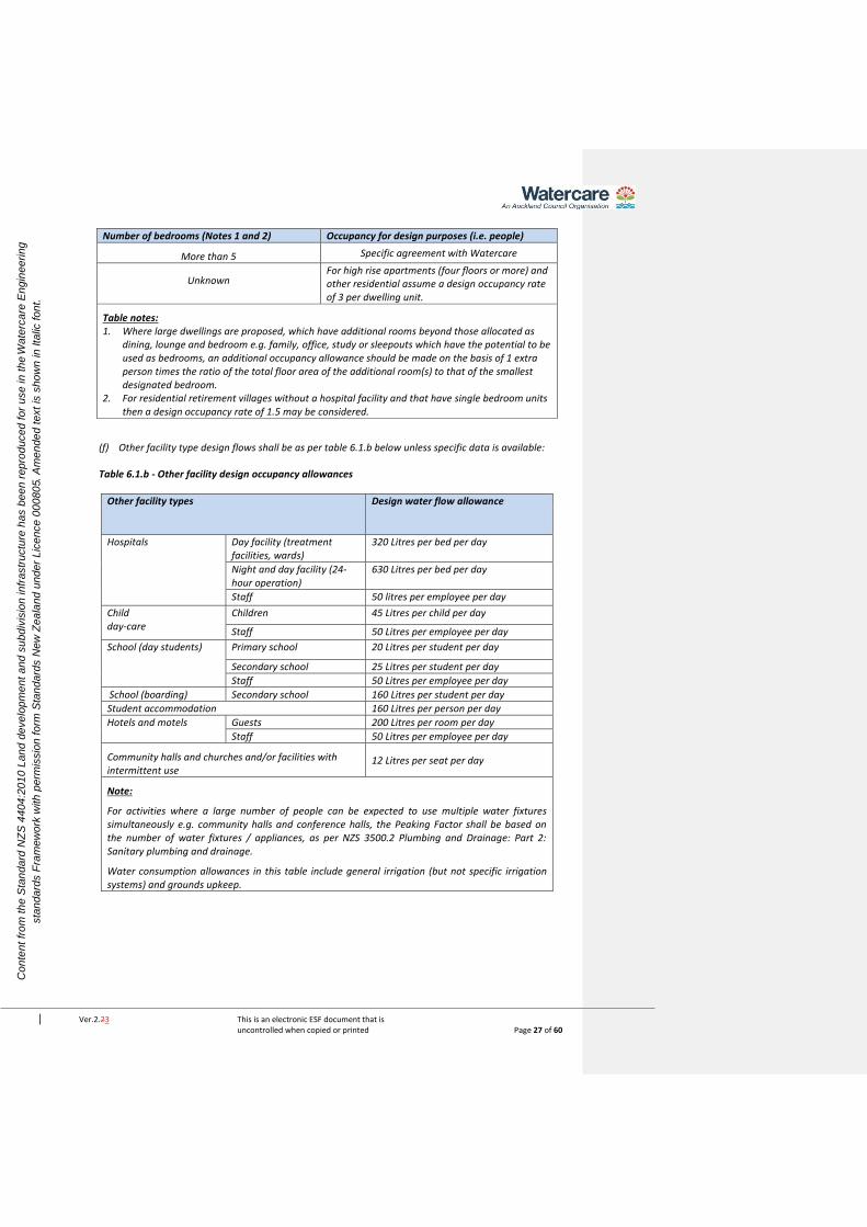
Number of bedrooms (Notes 1 and 2) Occupancy for design purposes (i.e. people)
More than 5 Specific agreement with Watercare
Unknown
For high rise apartments (four floors or more) and other residential assume a design occupancy rate of 3 per dwelling unit.
Table notes: 1. Where large dwellings are proposed, which have additional rooms beyond those allocated as
dining, lounge and bedroom e.g. family, office, study or sleepouts which have the potential to be used as bedrooms, an additional occupancy allowance should be made on the basis of 1 extra person times the ratio of the total floor area of the additional room(s) to that of the smallest designated bedroom.
2. For residential retirement villages without a hospital facility and that have single bedroom units then a design occupancy rate of 1.5 may be considered.
(f) Other facility type design flows shall be as per table 6.1.b below unless specific data is available:
Table 6.1.b - Other facility design occupancy allowances
Other facility types Design water flow allowance
Hospitals
Day facility (treatment facilities, wards)
320 Litres per bed per day
Night and day facility (24-hour operation)
630 Litres per bed per day
Staff 50 litres per employee per day
Child day-care
Children 45 Litres per child per day
Staff 50 Litres per employee per day
School (day students) Primary school 20 Litres per student per day
Secondary school 25 Litres per student per day
Staff 50 Litres per employee per day
School (boarding) Secondary school 160 Litres per student per day
Student accommodation 160 Litres per person per day
Hotels and motels Guests 200 Litres per room per day
Staff 50 Litres per employee per day
Community halls and churches and/or facilities with intermittent use
12 Litres per seat per day
Note:
For activities where a large number of people can be expected to use multiple water fixtures simultaneously e.g. community halls and conference halls, the Peaking Factor shall be based on the number of water fixtures / appliances, as per NZS 3500.2 Plumbing and Drainage: Part 2: Sanitary plumbing and drainage.
Water consumption allowances in this table include general irrigation (but not specific irrigation systems) and grounds upkeep.

Ver.2.23 This is an electronic ESF document that is uncontrolled when copied or printed Page 28 of 60
Co
nte
nt
fro
m t
he
Sta
nd
ard
NZ
S 4
40
4:2
01
0 L
an
d d
eve
lop
me
nt
an
d s
ub
div
isio
n in
fra
str
uctu
re h
as b
ee
n r
ep
rod
uce
d f
or
use
in
th
e W
ate
rca
re E
ng
ine
eri
ng
sta
nd
ard
s F
ram
ew
ork
with
pe
rmis
sio
n f
orm
Sta
nd
ard
s N
ew
Ze
ala
nd
un
de
r L
ice
nce
00
08
05.
Am
en
de
d t
ext
is s
ho
wn
in
Ita
lic f
on
t.
(g) Commercial demand must be established on the particular commercial development as the basis of
design. Where there is no specific industry design data the criteria as per table 6.1.c below shall be
followed:
Table 6.1.c – Wet and dry commercial assumed design allowances
Commercial activity type Design water flow allowance
Dry retail (Note 1) (where kitchen/toilets are not normally made available to customers)
1 person per 50m2 net floor area at 65 litres per person per day.
Office buildings and dry retail where toilet facilities, etc. are provided to customers.
1 person per 15m2 net floor area at 65 litres per person per day.
Wet retail (Note 2): Food and or beverage retail/preparation e.g. coffee shop, restaurant, bar, butcher, fresh fruit and vegetable retail.
15 litres per day per net m2 of floor area (including kitchen and dining areas).
Table notes:
1. Dry retail is where water is normally only used by staff for their own personal food preparation / toileting needs. Examples include: clothes shop, hardware retail.
2. Wet retail is where water is used to prepare food product for customers. Examples include: café, lunch bar, restaurant, butchery, fresh fruit and vegetable, food court-bar and supermarkets.
3. Assuming no significant irrigation. Important: Net floor area is the total floor area of the building (exclude any open land areas),, less non-productive areas, such as: lobbies; lifts; machine rooms; electrical services; stairwells; fire escapes; corridors and other passages used in common with other occupiers; car parking areas; etc. If net area is unknown, and the type of buildings are unknown, it can be assumed that the Net floor area is = 80% of the gross floor area of the building. As a guide to how activities will be assessed, commercial washing activities such as car / boat washing activities, etc. would be regarded as a “wet-industry” and not as a commercial - wet retail, as the water is being used as a part of a process (washing). Large-scale food-processing (i.e. for supply to commercial customers, as opposed to on-site retail customers) would be regarded as an industrial type activity. Preparation / manufacture of non-food based products, is also regarded as an industrial activity. Industry design flows are detailed in the section below.
(h) Industrial demand must be established on the particular industrial development as the basis of design.
Where there is no specific industry design data the criteria as per table 6.1.d below shall be followed:
Table 6.1.d – Wet and dry Industrial assumed design allowances
Dry industry activity type Routine Peak Daily Usage Litres per square metre per day (L/m2/d)
Light water users, or up to 2 storeys (Note 1)
4.5
Medium water users, or 2 to 5 storeys (Note 2)
6

Ver.2.23 This is an electronic ESF document that is uncontrolled when copied or printed Page 29 of 60
Co
nte
nt
fro
m t
he
Sta
nd
ard
NZ
S 4
40
4:2
01
0 L
an
d d
eve
lop
me
nt
an
d s
ub
div
isio
n in
fra
str
uctu
re h
as b
ee
n r
ep
rod
uce
d f
or
use
in
th
e W
ate
rca
re E
ng
ine
eri
ng
sta
nd
ard
s F
ram
ew
ork
with
pe
rmis
sio
n f
orm
Sta
nd
ard
s N
ew
Ze
ala
nd
un
de
r L
ice
nce
00
08
05.
Am
en
de
d t
ext
is s
ho
wn
in
Ita
lic f
on
t.
Heavy water users, or 5 to 10 storeys (Note 3)
11.0
Very heavy water users (Note 4)
> 11.0 Specific design required
Table notes:
1. A light water usage industry is a relatively dry and clean trade where industrial practices do not include process water usage. Showers provided for personnel’s ad-hoc use would still fall into the ‘light water usage’ category.
2. A medium water usage industry in a dirty trade where good industrial practice requires regular water usage and showers are in daily use because of commercial activities that require staff to have washing facilities, but there is no process water usage.
3. A heavy water usage industry in a trade that use water as a part of commercial activities in moderate quantities, but is not a Wet Industry, as defined in note 4 below. Wherever possible, the design flow for a heavy water usage industry should be checked against known water consumption rates. The Design Engineer shall submit evidence of these checks as a part of the application.
4. A very heavy water usage industry in a trade use in excess of 12 L/m2/d on a routine basis. 5. Assuming no significant irrigation.
(i) As approved by Watercare based on supporting evidence.
6.3.5.7 Sizing of mains
Tables 6.2 and 6.3 may be used as a guide for sizing mains.
Table 6.2 – Empirical guide for principal main sizing
Nominal
Internal
diameter
Capacity of main (single direction feed only)
Residential
(lots)
Rural
Residential
(lots)
General/light
industrial
(ha)
High usage
industrial
(ha)
100 40 10 – –
150 160 125 23 –
200 400 290 52 10
225 550 370 66 18
250 650 470 84 24
Table 6.3 – Empirical guide for sizing rider mains
DN 50 Rider mains
Pressure Maximum number of dwelling units
One end supply Two end supply
High > 600 kPa 20 40
Medium 400 – 600 kPa 15 30
Low < 400 kPa 7 15
6.3.5.8 Water district zones
All areas will have limits of acceptable site ground elevation and/or pressure requirements in a water district zone due to hydraulic grade (HGL) constraints. In some cases the installation of a pressure reducing valve to create a pressure reduced zone or the installation of a pump station to create a pressure boosted zone may be considered to control the pressure delivered to an area. In these cases the designer shall consult with Watercare to confirm if the proposal is acceptable for long term operations.

Ver.2.23 This is an electronic ESF document that is uncontrolled when copied or printed Page 30 of 60
Co
nte
nt
fro
m t
he
Sta
nd
ard
NZ
S 4
40
4:2
01
0 L
an
d d
eve
lop
me
nt
an
d s
ub
div
isio
n in
fra
str
uctu
re h
as b
ee
n r
ep
rod
uce
d f
or
use
in
th
e W
ate
rca
re E
ng
ine
eri
ng
sta
nd
ard
s F
ram
ew
ork
with
pe
rmis
sio
n f
orm
Sta
nd
ard
s N
ew
Ze
ala
nd
un
de
r L
ice
nce
00
08
05.
Am
en
de
d t
ext
is s
ho
wn
in
Ita
lic f
on
t.
6.3.5.9 Watermain hydraulic design input and output
Inputs to the design process include:
(a) Hydraulic grades (HGL) at point of connection to existing Watercare network;
(b) Existing system hydraulic capacity;
(c) Water demand (low, average, peak) in l/s, and diurnal profile;
(d) Proposed land use and water use activities;
(e) Hydraulic loss functions;
(f) Fire flow targets for the proposed site;
(g) An understanding of the general operating philosophy and design constraints of the water district
zone the proposed development is connecting to; and
(h) Elevation assumptions at proposed water meter locations.
The outputs of water main hydraulic design shall include:
(i) Size of watermains (nominal diameter);
(j) Maximum, average and minimum design pressure at each of the water meter locations;
(k) The pressure class/rating of pipeline system components;
(l) Surge analysis results;
(m) Pipe headloss (m/km) and velocity (m/s) compliance with low, average, peak demand and firefighting
demand scenarios;
(n) Specification of the maximum and minimum allowable operating pressure;
(o) Flow and pressure compliance with low, average, peak demand and firefighting demand scenarios;
and
(p) Reticulation layout that provides security of supply to end users.
6.3.5.10 Design pressure
The design pressures are the limiting pressures for operation of a water supply system including any allowance
for variation of usage in the future.
The minimum design pressure is either the minimum pressure defined by Watercare or some higher pressure
selected to control (minimise) the range of pressures experienced over the normal diurnal variation in the
system.
Unless otherwise specified by Watercare, the design pressure shall be between 250kPa and 800kPa (25 m to
80 m).
C6.3.5.10
A design pressure of 250kPa to 800kPa is set at the water meter. Specific consideration should be given for
multi-storeyed buildings or areas of significant contours. The design pressure differs from Watercare’s
customer contract.
6.3.5.10.1 Operating pressure/working pressure
The operating pressure shall not exceed the re-rated pressure class/rating or the operating pressure limit of
the pipeline components at that location.
6.3.6 Water quality
A number of factors in a network can adversely affect the quality of the water in the system. The network
design shall ensure that the water quality at each property complies with the Drinking-water Standards for

Ver.2.23 This is an electronic ESF document that is uncontrolled when copied or printed Page 31 of 60
Co
nte
nt
fro
m t
he
Sta
nd
ard
NZ
S 4
40
4:2
01
0 L
an
d d
eve
lop
me
nt
an
d s
ub
div
isio
n in
fra
str
uctu
re h
as b
ee
n r
ep
rod
uce
d f
or
use
in
th
e W
ate
rca
re E
ng
ine
eri
ng
sta
nd
ard
s F
ram
ew
ork
with
pe
rmis
sio
n f
orm
Sta
nd
ard
s N
ew
Ze
ala
nd
un
de
r L
ice
nce
00
08
05.
Am
en
de
d t
ext
is s
ho
wn
in
Ita
lic f
on
t.
New Zealand 2005 (Revised 2008). The requirement to protect water supplies from the risk of backflow is
stated in the Health (Drinking Water) Amendment Acts 69ZZZ and this shall be adhered to.
6.3.6.1 Materials
All parts of the water supply system in contact with drinking water shall be designed using components and
materials that comply with AS/NZS 4020.
A minimum pressure rating of PN12 shall be used for all pipe material and PN16 for all components. Refer to
Watercare material supply standards.
6.3.6.2 Prevention of backflow
Drinking water supply systems shall be designed and equipped to prevent backflow. The location and
operation of hydrants, air valves, and scours shall ensure no external water enters the system through
negative pressure from normal operation.
Backflow preventers must be tested by a registered independent qualified person (IQP) under the building Act
2004 and the Health (Drinking Water) Amendment Act 2007. Backflow prevention shall be installed on all
water supplies at the boundary area between public and private pipe ownership. Refer to the Auckland Council
Water Supply and Wastewater Network Bylaw, July 2015, for requirements to protect water quality.
6.3.6.2.1 Location of backflow devices
The preferred location of backflow devices is within 500mm of the property boundary in the public road reserve
to allow access for ongoing maintenance and inspection. Where this is not practicable the backflow prevention
device may be installed in private property within 1m of the property boundary. There may be no other
connection upstream of the backflow preventer. Source backflow prevention requires special certification and
must consider suitable accessibility for maintenance and certification.
6.3.6.2.2 Ownership of backflow devices
Backflow devices installed in public property are owned by Watercare whilst devices installed on private
property may be considered for private ownership under special arrangement with Watercare. The special
arrangement shall include arrangements that will allow Watercare access to test the device at any time. Where
access is prevented, Watercare may act in accordance with section 6.3.6.2.7. Under both ownership locations,
the cost of installation, maintenance and annual certification is borne by the private property owner.
6.3.6.2.3 Service leads
Any service lead shall be installed with minimum a dual check valve. Depending on the property risk profile the
backflow prevention device may need to be upgraded accordingly at time of connection/meter installation, or
at any time when the supply risk level changes. See section 6.3.6.2.5.
6.3.6.2.4 Fire supplies
All private fire supply systems shall be fitted with a suitable backflow prevention device. The minimum risk level
for fire systems shall be medium, but high risk level for fire supplies with chemical additives. See section
6.3.6.2.5.
6.3.6.2.5 Levels of risk
Hazards and classifications shall be to G12/AS1, section 3.0 of the Building Code. The complete site must be
surveyed to determine the backflow hazard rating level.

Ver.2.23 This is an electronic ESF document that is uncontrolled when copied or printed Page 32 of 60
Co
nte
nt
fro
m t
he
Sta
nd
ard
NZ
S 4
40
4:2
01
0 L
an
d d
eve
lop
me
nt
an
d s
ub
div
isio
n in
fra
str
uctu
re h
as b
ee
n r
ep
rod
uce
d f
or
use
in
th
e W
ate
rca
re E
ng
ine
eri
ng
sta
nd
ard
s F
ram
ew
ork
with
pe
rmis
sio
n f
orm
Sta
nd
ard
s N
ew
Ze
ala
nd
un
de
r L
ice
nce
00
08
05.
Am
en
de
d t
ext
is s
ho
wn
in
Ita
lic f
on
t.
The types of devices shall be considered based on the table below:
Hazard level Boundary device Source device (special certification with Watercare)
Low hazard Dual check valve Dual check valve Vacuum breaker
Medium hazard Double check valve Double check detector
Double check valve Spill proof vacuum breaker
High hazard Reduced pressure zone Reduced pressure zone detector
Reduced pressure zone Registered air gap
6.3.6.2.6 Backflow device approval
Backflow preventer devices shall comply with the requirements of Watercare’s material supply standard. When
a connection is made to the Watercare local water supply network an approved IQP shall test and certify the
backflow preventer.
6.3.6.2.7 Disconnection of water supply
The water supply shall be disconnected in accordance with the Local Government Act 2002 and the Auckland
Council Water Supply and Wastewater Network Bylaw 2015 under the following circumstance, but not limited
to:
• Unprotected supply with direct or indirect connection to possible contaminants
• Where the level of risk increases (change of use) and the device is not upgraded accordingly
• Where the device is not suitable or suitably installed for the level of hazard protection
• Expired backflow prevention device certification
Disconnection may be effected immediately where there is serious risk to the public water supply.
6.3.6.3 Water age
Drinking water supply systems shall be designed to minimise water age to ensure no unacceptable
deterioration of water quality. This shall include:
(a) Mains with dead ends (or termination points – see 6.3.17) shall be avoided by the provision of looped
watermains. Particular care shall be taken at the boundaries between supply zones where dead ends
shall be avoided or minimised whilst maintaining existing district zone boundaries;
(b) Mains for short runs shall be reduced in size or looped, for example no-exit roads (see figure 6.6);
(b)(c) Watercare may at its discretion require the developer to implement a system to improve the
water quality where development uptake versus overall size affects the water grade of the area. This
may be in the form of temporary dosing systems and flushing. A development staging strategy shall be
provided to Watercare with commitment to provide for any associated costs before connecting to the
Watercare system.
6.3.7 Flow velocities
In practice it is desirable to avoid unduly high or low flow velocities. Pipelines shall be designed for normal flow
velocities at peak periods within the range of 0.5 to 2.0 m/s.
For pumping mains an economic appraisal may be required to determine the most economical diameter of
pumping main to minimise the combined capital and discounted pumping cost. The resulting velocity will
normally lie in the range 0.8 m/s to 3.0 m/s. All pump station design considerations should be consulted with
Watercare in the first instance.
Ver.2.23 This is an electronic ESF document that is uncontrolled when copied or printed Page 33 of 60
Co
nte
nt
fro
m t
he
Sta
nd
ard
NZ
S 4
40
4:2
01
0 L
an
d d
eve
lop
me
nt
an
d s
ub
div
isio
n in
fra
str
uctu
re h
as b
ee
n r
ep
rod
uce
d f
or
use
in
th
e W
ate
rca
re E
ng
ine
eri
ng
sta
nd
ard
s F
ram
ew
ork
with
pe
rmis
sio
n f
orm
Sta
nd
ard
s N
ew
Ze
ala
nd
un
de
r L
ice
nce
00
08
05.
Am
en
de
d t
ext
is s
ho
wn
in
Ita
lic f
on
t.
The following factors shall be considered in determining flow velocity:
(a) Avoid stagnation;
(b) Minimise turbidity (large fluctuations in flow rates can dislodge the biological slime or stir up settled
solids in pipelines);
(c) Pressure;
(d) Surge;
(e) Pumping facilities;
(f) Pressure reducing devices;
(g) Pipe lining materials.
6.3.7.1 Surge analysis
A surge analysis shall be undertaken for any pipeline within a pumped system or system containing automated
valves. The source of any significant pressure surges or high-pressure areas shall be identified and remedial
measures to minimise pressure surges designed and specified.

Ver.2.23 This is an electronic ESF document that is uncontrolled when copied or printed Page 34 of 60
Co
nte
nt
fro
m t
he
Sta
nd
ard
NZ
S 4
40
4:2
01
0 L
an
d d
eve
lop
me
nt
an
d s
ub
div
isio
n in
fra
str
uctu
re h
as b
ee
n r
ep
rod
uce
d f
or
use
in
th
e W
ate
rca
re E
ng
ine
eri
ng
sta
nd
ard
s F
ram
ew
ork
with
pe
rmis
sio
n f
orm
Sta
nd
ard
s N
ew
Ze
ala
nd
un
de
r L
ice
nce
00
08
05.
Am
en
de
d t
ext
is s
ho
wn
in
Ita
lic f
on
t.
6.3.8 System layout
6.3.8.1 General
Watermains shall be located in the road reserve. The location shall be specified by the Auckland Council or
Watercare, within the road reserve or space allocation nominated by the Corridor Manager. Where approved
by the Auckland Council or Watercare, watermains may be located in a public reserve or park. In some
instances an easement may be required depending on the discretion of the parks manger.
Watermains shall:
(a) Be aligned parallel to property boundaries, and typically located in the berm;
(b) Not traverse steep gradients; and
(c) Be located to maintain adequate clearance from structures and other infrastructure. Refer section
6.3.9.
A typical cross section layout for public roads is provided below:

Ver.2.23 This is an electronic ESF document that is uncontrolled when copied or printed Page 35 of 60
Co
nte
nt
fro
m t
he
Sta
nd
ard
NZ
S 4
40
4:2
01
0 L
an
d d
eve
lop
me
nt
an
d s
ub
div
isio
n in
fra
str
uctu
re h
as b
ee
n r
ep
rod
uce
d f
or
use
in
th
e W
ate
rca
re E
ng
ine
eri
ng
sta
nd
ard
s F
ram
ew
ork
with
pe
rmis
sio
n f
orm
Sta
nd
ard
s N
ew
Ze
ala
nd
un
de
r L
ice
nce
00
08
05.
Am
en
de
d t
ext
is s
ho
wn
in
Ita
lic f
on
t.
6.3.8.2 Principal and rider mains layout
For residential areas, a principal water main of minimum 100mm internal diameter (NB), fitted with fire
hydrants, shall be laid on one side of all public roads in every residential development. A rider main of
minimum 50mm internal diameter (NB) shall be laid along the road frontage of all lots not fronted by the
principal main. A minimum 50 NB rider main shall also be provided for service connections where the principal
main is 300 NB or larger. The principal mains serving commercial and industrial areas shall be minimum 150 NB
laid on both sides of the road. To facilitate future development, watermains shall be laid across the full road
frontage of the site at the developer’s cost.
6.3.8.3 Mains layout
In determining the general layout of mains, the following factors shall be considered:
(a) Main location to allow easy access for repairs and maintenance;
(b) Whether system security, maintenance of water quality, and ability to clean mains meet operational
requirements;
(c) Location of valves for shut-off areas and zone boundaries (see 6.3.14);
(d) Avoidance of dead ends by use of looped mains or rider mains;
(e) Provision of dual or alternate feeds to minimise service risk;
(f) Consider material type and evidence of engineering evaluation, i.e. location to fuel stations; and
(g) Compatibility with Watercares’s long term management strategy and plan for the overall district zone.
6.3.8.4 Watermains in private property
Watermains shall only be installed in the public road reserve. Public watermains in private property, right of
ways (ROW) and private roads is not permitted.
6.3.8.5 Types of system configuration
Network layouts shall be established in accordance with Watercare’s practice to provide security of supply and
zone management, and interconnected ring systems.
6.3.8.6 Watermains near trees
Locating watermains within the root zone of trees is not allowed.
6.3.8.7 Shared trenching
Where shared trenching is approved the pipe structural calculations shall consider the pipe structural impact
and minimum clearances from other services. See section 6.3.9.
6.3.8.8 Rider mains and duplicate principal mains
A rider main shall be laid along the road frontage of all lots not fronted by a principal main.
Duplicate principal mains are required to provide adequate fire protection in the following cases:
(a) Arterial roads or roads with a central dividing island;
(b) Roads with split elevation;
(c) Roads with rail or tram lines;
(d) Urban centres;
(e) Parallel to large distribution mains that are not available for service connections;
(f) Commercial and industrial areas nominated by the Auckland Council;
(g) Where required by SNZ PAS 4509.

Ver.2.23 This is an electronic ESF document that is uncontrolled when copied or printed Page 36 of 60
Co
nte
nt
fro
m t
he
Sta
nd
ard
NZ
S 4
40
4:2
01
0 L
an
d d
eve
lop
me
nt
an
d s
ub
div
isio
n in
fra
str
uctu
re h
as b
ee
n r
ep
rod
uce
d f
or
use
in
th
e W
ate
rca
re E
ng
ine
eri
ng
sta
nd
ard
s F
ram
ew
ork
with
pe
rmis
sio
n f
orm
Sta
nd
ard
s N
ew
Ze
ala
nd
un
de
r L
ice
nce
00
08
05.
Am
en
de
d t
ext
is s
ho
wn
in
Ita
lic f
on
t.
6.3.8.9 Crossings
Water main crossings of roads, railway lines, and underground services shall be at right angles. Ducting and
additional protection of the crossing service is subject to the affected authority’s requirements. In any event the
water main crossing shall be sized at minimum 100 NB. Mains should be located and designed to minimise
maintenance and crossing restoration. Watercare may require extra mechanical protection for the pipes or
different pipe materials to minimise the need for future maintenance.
6.3.8.10 Crossings of waterways or reserves
All crossings of waterways or reserves shall be specific designs to suit Watercare’s requirements.
Crossings shall be sized minimum 100 NB and, as far as practicable, be at right angles to the waterway or
reserve. Watercare prefers below waterway invert crossings. Refer to 6.3.8.12 where it can be demonstrated
that such a crossing is not practicable. When the pipeline is placed under the invert level of a waterway it may
require mechanical protection by concrete encasement or steel or other acceptable pipe duct. Different
pipeline materials may need to be used for the crossing.
6.3.8.11 Location marking of valves and hydrants
The location marking of valves and fire hydrants shall be to SNZ PAS 4509 and as shown on the standard
drawings for Watercare’s Code of Practice for Land Development and Subdivision – Water drawing set,
document number DW02.
6.3.8.12 Location of watermains on bridges
The pipe bridge must not be integrated with the bridge support structure. The design must provide for safe and
unrestricted access for maintenance, upgrade or replacement. The pipe shall be positioned clear of the 1% AEP
flood levels. The pipe and supports shall be structurally designed to meet the following conditions (refer section
6.3.12):
(a) Empty and full static loads
(b) Any dynamic loads and vibration
(c) Expansion and contraction
(d) Seismic action.
Timber supports are unacceptable. Provision shall be made for access and clearances to maintain the pipe,
connecting structures, drainage, articulation joints, valves and associated fittings as necessary.
Unauthorised bridge access (i.e. onto the pipe) shall be prevented with an adequate barrier structures and if
necessary on-bridge railing for fall protection.
The following pipe material options can be considered:
(a) Polyethylene pipe, however this material must be butt welded and supported inside a full length
carrier pipe of suitable rigidity and durability. Cradles are not acceptable. The carrier pipe must be of
suitable internal diameter to allow both future pipe size upgrades and thermal expansion and
contraction.
(b) Steel (lined mild steel or stainless steel). Welded or flange joints. Pipe hangers or supports should be
fully welded solution to reduce corrosion and simplify maintenance
(c) Ductile iron with flanged joints with hangers or supports that prevent galvanic corrosion and
encourage water run-off.
A formal agreement with the bridge owner must provide Watercare with the ability to access, operate and
maintain the pipe on the bridge.

Ver.2.23 This is an electronic ESF document that is uncontrolled when copied or printed Page 37 of 60
Co
nte
nt
fro
m t
he
Sta
nd
ard
NZ
S 4
40
4:2
01
0 L
an
d d
eve
lop
me
nt
an
d s
ub
div
isio
n in
fra
str
uctu
re h
as b
ee
n r
ep
rod
uce
d f
or
use
in
th
e W
ate
rca
re E
ng
ine
eri
ng
sta
nd
ard
s F
ram
ew
ork
with
pe
rmis
sio
n f
orm
Sta
nd
ard
s N
ew
Ze
ala
nd
un
de
r L
ice
nce
00
08
05.
Am
en
de
d t
ext
is s
ho
wn
in
Ita
lic f
on
t.
6.3.9 Clearances
6.3.9.1 Clearance from underground services
Watermains that are public and installed in the proximity of other services shall comply with Watercare’s
minimum clearance requirements. The specific design may require a greater clearance.
The minimum vertical and horizontal clearances are shown in Table 6.4.
Table 6.4 – Clearances between watermains and underground services (6)
Utility
(Existing service)
Minimum horizontal
clearance (mm) (Fig. 6.1 ‘X’)
Minimum
vertical
clearance(1)
(mm) (Fig 6.1
‘Y’)
New main size
DN ≤250 DN > 250
Watermains DN ≥ 600 See Watercare’s general civil
constructiontransmission design standard.
Watercare may consider specific clearances for
larger mains due to operational reasons.
Transmission watermains 600 > DN ≥375 600 500
Watermains DN <375 300(2) 150
Gas mains 300(2) 150
Telecommunications conduits and cables 300(2) 150
Electricity conduits and cables 500 225
Wastewater and Storm water pipes 1000/600(4) 500(3)
Kerbs 150 600
NOTE –
All clearances are measured as the inside open spacing between the external walls of services.
(1) Vertical clearances apply when watermains cross another utility service, except in the case of
wastewater when a vertical separation shall always be maintained, even when the main and
wastewater pipe are parallel. The main should always be located above the wastewater pipe to
minimise the possibility of backflow contamination in the event of a main break.
(2) Clearances can be further reduced to 150 mm for lengths up to 2 m when passing
installations such as poles, pits, and small structures, providing the structure is not destabilised
in the process or that the structural integrity of the trench is compromised.
(3) Watermains shall always cross over wastewater and stormwater drains.
(4) When the wastewater or storm water pipe is at the minimum vertical clearance below the
water main (500 mm), maintain a minimum horizontal clearance of 1000 mm. This minimum
horizontal clearance can be progressively reduced to 600 mm as the vertical clearance is
increased to 750 mm.
(5) Clearance from kerb and channel shall be measured from the nearest edge of the concrete.
(6) Where a main crosses other services, it shall cross at an angle as near as possible to 90o.

Ver.2.23 This is an electronic ESF document that is uncontrolled when copied or printed Page 38 of 60
Co
nte
nt
fro
m t
he
Sta
nd
ard
NZ
S 4
40
4:2
01
0 L
an
d d
eve
lop
me
nt
an
d s
ub
div
isio
n in
fra
str
uctu
re h
as b
ee
n r
ep
rod
uce
d f
or
use
in
th
e W
ate
rca
re E
ng
ine
eri
ng
sta
nd
ard
s F
ram
ew
ork
with
pe
rmis
sio
n f
orm
Sta
nd
ard
s N
ew
Ze
ala
nd
un
de
r L
ice
nce
00
08
05.
Am
en
de
d t
ext
is s
ho
wn
in
Ita
lic f
on
t.
Figure 6.1 Service clearance measurements
6.3.9.2 Clearance from structures
Pipes adjacent to existing buildings and structures shall be located clear of the ‘zone of influence’ of the
building foundations. If this is not possible, a specific design shall be undertaken to cover the following:
(a) Protection of the pipeline;
(b) Long term maintenance access to the pipeline;
(c) Protection of the existing structure or building;
(d) Consideration to building overhangs and clearances; and
(e) Building over watermains is not permitted.
The protection shall be specified by the designer for evaluation and acceptance by Watercare. Table 6.5 may
be used as a guide for minimum clearances for access to watermains.
Table 6.5 – Minimum clearance from structures
Pipe diameter DN Clearance to wall or building
(mm)
<100 600
100 – 150 1000
200 – 250 1500
For the process to construct close to Watercare’s networks please refer to the ‘Works Over’ page on
Watercare’s website.
6.3.9.3 Clearance from high voltage transmission facilities
Watermains constructed from metallic materials shall generally not be located close to high voltage
transmission lines and other facilities. Special design shall be undertaken if it is necessary to locate such mains
close to such facilities.
C6.3.9.3
For any situation where a metallic pipeline is located in proximity of electrical transmission lines, particular
attention is drawn to AS/NZS 4853 Electrical hazards on metallic pipelines. Similarly, A Guide to Power System
Earthing Practice published by the Electrical Engineers Association is a useful reference (www.eea.co.nz)

Ver.2.23 This is an electronic ESF document that is uncontrolled when copied or printed Page 39 of 60
Co
nte
nt
fro
m t
he
Sta
nd
ard
NZ
S 4
40
4:2
01
0 L
an
d d
eve
lop
me
nt
an
d s
ub
div
isio
n in
fra
str
uctu
re h
as b
ee
n r
ep
rod
uce
d f
or
use
in
th
e W
ate
rca
re E
ng
ine
eri
ng
sta
nd
ard
s F
ram
ew
ork
with
pe
rmis
sio
n f
orm
Sta
nd
ard
s N
ew
Ze
ala
nd
un
de
r L
ice
nce
00
08
05.
Am
en
de
d t
ext
is s
ho
wn
in
Ita
lic f
on
t.
6.3.9.4 Deviation of mains around structures
Deviation of a pipeline around an obstruction can be achieved by deflection of the pipeline at joints, to the
angular deflection limits stated by the pipe joint manufacturer and with suitably restrained fitting bends.
Permitted angular deflection varies with pipe material, pipe wall thickness, pipe PN class, joint type, design and
geometry. Some joint types are specifically designed to accommodate angular deflection. PVC and PE pipes
may also be curved along the pipe barrel, between joints, to a radius of curvature not less than that stated by
the pipe manufacturer. Curved watermains require Watercare approval and may not be allowed due to pipe
joint stresses or operational constraints.
6.3.10 Pipe selection
The selection of the appropriate pipe material, sizes, and pressure classes shall be based on system demands.
See section 6.3.10 for Watercare’s minimum pipe pressure ratings.
6.3.10.1 Standard pipe sizes
The principal main sizes shall be standardised as DN 100, 150, 200, 250 nominal diameters only.
Watercare follows standard nominal pipe sizes to ISO standards. When larger pipes are required, contact
Watercare.
6.3.10.2 Minimum pipe sizes
Minimum pipe diameters shall be as follows, where DN is the nominal pipe diameter (for CLS or PE use nominal
bore size instead of DN):
(a) DN 50 for rider mains in residential zones;
(b) DN 100 for principal mains in residential zones;
(c) DN 150 for industrial or commercial zones; and
(d) DN 100 minimum for stream, road, railway and reserve crossings.
Watercare may also specify minimum pipe diameters for other identified areas such as CBDs and high density
residential zones.
6.3.10.3 Pipe PN class (pressure rating)
Pipe PN class is selected on the basis of the design pressure (head) calculated for the various sections of the
reticulation network. This may be varied by specific operational requirements specified by Watercare. The
minimum pipe pressure rating shall be PN12.
6.3.10.3.1 Design pressure
The design pressure (head) for the mains to be installed shall be based on the following:
Design pressure, (m) = Maximum Supply Pressure, (m above the level datum used for the ground level)
+ Surge Allowance, (m) (see 6.3.7.1)
– Lowest Ground Level (GL) of the proposed main, (m above datum).
The design pressure (m head) shall be used for:
(a) Selection of pipe materials and classes;
(b) Selection of pipe fitting types and classes.

Ver.2.23 This is an electronic ESF document that is uncontrolled when copied or printed Page 40 of 60
Co
nte
nt
fro
m t
he
Sta
nd
ard
NZ
S 4
40
4:2
01
0 L
an
d d
eve
lop
me
nt
an
d s
ub
div
isio
n in
fra
str
uctu
re h
as b
ee
n r
ep
rod
uce
d f
or
use
in
th
e W
ate
rca
re E
ng
ine
eri
ng
sta
nd
ard
s F
ram
ew
ork
with
pe
rmis
sio
n f
orm
Sta
nd
ard
s N
ew
Ze
ala
nd
un
de
r L
ice
nce
00
08
05.
Am
en
de
d t
ext
is s
ho
wn
in
Ita
lic f
on
t.
6.3.10.3.2 Minimum pipe PN
The minimum pressure rating for pipe shall be PN12 and for fittings PN16 on water reticulation mains. For
some pipe materials Watercare require greater minimum pressure class. Designers shall verify Watercare’s
minimum requirement before specifying the required pipe PN. Refer to Watercare’s material supply standard.
6.3.10.3.3 Nominated pipe PN
In some cases Watercare may nominate a pipe PN (such as PN 16) for pressure pipes and fittings to standardise
on a limited number of pipe PNs, or to allow future operational flexibility within the system. Where this is the
case, the design pressure used as the basis for system design shall not exceed Watercare’s specified operating
pressure limit associated with the designated pipe PN.
6.3.10.3.4 Pumped mains
When booster pump stations are considered, the requirements shall be reviewed with Watercare in the first
instance. Telemetry requirements are area specific and will be clarified during the process of assessing the
design. For general guidance refer to Watercare’s Water pump station standard and drawings for networks
(document number DP-15 and DW04).
For watermains in pumped systems, a detailed surge analysis shall be conducted unless otherwise directed by
Watercare to ensure:
(a) The appropriate surge pressure is included in the calculated design head;
(b) Surge control devices are included in the system design, where identified by the detailed analysis, to
protect the network or control pressure fluctuations in the supply to customers, or both.
6.3.10.4 Pipe materials
For acceptable pipe materials and Standards see Watercare’s material supply standards.
C6.3.10.4
When steel watermains are considered, early discussions with Watercare should include the installation of a
cathodic protection system. Cathodic protection systems require ongoing monitoring; suitable arrangements
for test points need to be considered.
6.3.11 Fire flow
The water reticulation system shall be designed to comply with SNZ PAS 4509.
Any shortfall between the fire flow required by the proposed development outside the Watercare minimum
design supply pressure and flow is the responsibility of the site owner to provide alternative fire protection
services, at the cost of the site owner.
6.3.11.1 Fire protection services
Many commercial and industrial developments require installation of special fire protection services. While it
is the responsibility of the site owner to provide these fire services, the developer shall design the water
reticulation system with consideration to the required demands, where these are known in advance and the
minimum design as stated in section 6.3.5.5 and 6.3.5.10. The site owner shall ensure that if any special fire
protection services require supply of water from Watercare’s reticulation, the design shall include the
protection of existing Watercare assets and consider the existing and future available pressure and flow during
normal operations.

Ver.2.23 This is an electronic ESF document that is uncontrolled when copied or printed Page 41 of 60
Co
nte
nt
fro
m t
he
Sta
nd
ard
NZ
S 4
40
4:2
01
0 L
an
d d
eve
lop
me
nt
an
d s
ub
div
isio
n in
fra
str
uctu
re h
as b
ee
n r
ep
rod
uce
d f
or
use
in
th
e W
ate
rca
re E
ng
ine
eri
ng
sta
nd
ard
s F
ram
ew
ork
with
pe
rmis
sio
n f
orm
Sta
nd
ard
s N
ew
Ze
ala
nd
un
de
r L
ice
nce
00
08
05.
Am
en
de
d t
ext
is s
ho
wn
in
Ita
lic f
on
t.
As development continues in a zone, or as required by Watercare to manage the water supply system, the
pressure and flow is likely to reduce. The design of special fire protection services shall also make allowance for
a future upgrade at the site owner’s cost when the system operating pressure and flow changes in the future to
other conditions within Watercare’s level of service criteria - refer 6.3.5.10.
6.3.12 Structural design
6.3.12.1 General
For installation conditions beyond those shown on the drawings, the pipeline installation, including non-
pipeline elements such as pump station chambers, shall be specifically designed to resist structural failure. The
design shall be in accordance with AS/NZS 2566.1 including the structural design commentary AS/NZS 2566.1
Supplement 1 and NZS 1170.5 including Supplement 1. Details of the final design requirements shall be shown
on the drawings.
Pipe bridge design shall be subject to specific structural design of the pipe and supports for empty and full static
loads, any dynamic loads and full seismic provisions. Also see section 6.3.8.12.
6.3.12.2 Seismic design
All pipes and structures shall be designed with adequate flexibility and special provisions to minimise risk of
damage during earthquake. Historical experience in New Zealand earthquake events suggests that suitable
pipe options, in seismically active areas, may include rubber ring joint PVC pipes PE pipes, ductile iron or steel
pipe. Specially designed flexible joints shall be provided at all junctions between pipes and rigid structures
(such as reservoirs, pump stations, bridges, and buildings) where pipe flexibility alone is not adequate to
accommodate movement. Where structures are closely spaced such as at pump stations, base isolation of the
area may be considered where minor actions are expected. Connecting to the base isolation area requires a
flexible connection.
C6.3.12.2
Guidance for pipe seismic design method and philosophy can found in “Seismic Guidelines for Water Pipelines”,
American Lifelines Alliance, 2005, or “Guidelines for Seismic Design of Buried Pipelines”, NICEE, 2007, or
Underground Utilities – Seismic assessment and design guidelines, Water NZ.
6.3.12.3 Structural consideration
Pipelines shall be designed to withstand all the forces and load combinations to which they may be exposed
including internal forces, external forces, temperature effects, settlement, and combined stresses. The
watermain design shall include the selection of the pipeline material, the pipe pressure class, and selection of
appropriate bedding material to suit site conditions. Consideration must be given to the future state or possible
interactions with the trench that could affect the bedding material’s ability to continue functioning as designed,
for example very fine self-compacting material may affect the cost of retaining the trench during replacement
or other construction work near the trench.
6.3.12.4 Internal forces
Pipelines shall be designed for the range of expected pressures, including transient conditions (surge and
fatigue) and maximum static head conditions. In the case of transient conditions the amplitude and frequency
shall be estimated. The allowance for surge included in the maximum design pressure shall not be less than
200 kPa. Transfer and distribution mains subject to negative pressure shall be designed to withstand a
transient pressure of at least 80 kPa below atmospheric pressure. A surge safety factor of 2 may be applied to
the normal operating pressure to estimate the surge pressure in lieu of a detailed surge analysis.
Formatted: Font: Italic

Ver.2.23 This is an electronic ESF document that is uncontrolled when copied or printed Page 42 of 60
Co
nte
nt
fro
m t
he
Sta
nd
ard
NZ
S 4
40
4:2
01
0 L
an
d d
eve
lop
me
nt
an
d s
ub
div
isio
n in
fra
str
uctu
re h
as b
ee
n r
ep
rod
uce
d f
or
use
in
th
e W
ate
rca
re E
ng
ine
eri
ng
sta
nd
ard
s F
ram
ew
ork
with
pe
rmis
sio
n f
orm
Sta
nd
ard
s N
ew
Ze
ala
nd
un
de
r L
ice
nce
00
08
05.
Am
en
de
d t
ext
is s
ho
wn
in
Ita
lic f
on
t.
6.3.12.5 External forces
The external forces to be taken into account shall include:
(a) Trench fill loadings (vertical and horizontal forces due to earth loadings);
(b) Surcharge;
(c) Groundwater, including the potential for floatation;
(d) Dead weight of the pipe and the contained water;
(e) Other forces arising during installation;
(f) Traffic loads;
(g) Temperature (expansion/contraction).
The consequences of external forces on local supports of pipelines shall also be considered.
6.3.12.6 Geotechnical investigations
The designer shall take into account any geotechnical requirements determined during the investigations
for the development. All geotechnical log reports shall be uploaded to the New Zealand Geotechnical
Database; https://www.nzgd.org.nz. Where required, standard special foundation conditions shall be
referenced on the drawings.
Special design requirements may apply in any area susceptible to land instability or soil liquefaction. For
indicative information refer to http://data.gns.cri.nz/geology. Geo-professionals are to satisfy themselves
of the correctness of the information and apply current knowledge when meeting any such special
requirements.
6.3.12.7 Pipe selection for special conditions
Pipeline materials and jointing systems shall be selected and specified to ensure:
(a) Structural adequacy considering ground conditions and water temperature;
(b) Water quality, considering the chemical concentration and temperature of the water, the influence of
applied stresses and lining material;
(c) Compatibility with aggressive or contaminated ground (consider HAIL sites), see section 6.3.3A;
(d) Suitability for the geotechnical conditions;
(e) Compliance with Watercare’s requirements.
6.3.12.8 Above-ground watermains
The design of above-ground watermains shall include the design of pipeline supports, maintenance and access
requirements, control of unbalanced thrusts and pipe thermal movements, and shall address exposure
conditions, such as corrosion protection, UV protection, freezing of watermains, and temperature de-rating
effects on materials.
In such situations the pipe materials, support, and restraint for the pipes and fittings shall be detailed on the
drawings.
Refer to section 6.3.8.12 for general requirements.
6.3.12.9 Trenchless technology
Trenchless technology shall be used as appropriate for alignments passing through or under:
(a) Environmentally sensitive areas;
(b) Built-up or congested areas to minimise disruption and reinstatement;

Ver.2.23 This is an electronic ESF document that is uncontrolled when copied or printed Page 43 of 60
Co
nte
nt
fro
m t
he
Sta
nd
ard
NZ
S 4
40
4:2
01
0 L
an
d d
eve
lop
me
nt
an
d s
ub
div
isio
n in
fra
str
uctu
re h
as b
ee
n r
ep
rod
uce
d f
or
use
in
th
e W
ate
rca
re E
ng
ine
eri
ng
sta
nd
ard
s F
ram
ew
ork
with
pe
rmis
sio
n f
orm
Sta
nd
ard
s N
ew
Ze
ala
nd
un
de
r L
ice
nce
00
08
05.
Am
en
de
d t
ext
is s
ho
wn
in
Ita
lic f
on
t.
(c) Railway and road crossings;
(d) Significant vegetation;
(e) Vehicle crossings.
Pressure pipes used for trenchless installation shall have suitable mechanically restrained joints, specifically
designed for trenchless application, which may include integral restraint seal systems, or heat fusion welded
joints.
Refer to Watercare’s General Civil Construction standard for acceptable trenchless installation methods and its
specific requirements.
The designer’s project execution plan shall detail the pipe structural limitations for the intended construction
method, the location of access pits and exit points and include a risk assessment to other services, abutting
surface and underground structures.
C6.3.12.9
Further information on trenchless technologies may be found in ‘Trenchless technology for installation of
cables and pipelines’ (Stein), ‘Trenchless technology – Pipeline and utility design, construction, and renewal’
(Najafi), and ‘Guidelines for horizontal directional drilling, pipe bursting, micro-tunnelling and pipe jacking’
(Australasian Society for Trenchless Technology)
6.3.12.10 Embedment
6.3.12.10.1 Minimum pipe cover
Pipeline cover shall be designed with depth to the top of the pipe measured to the final surface level:
(a) In berms a minimum cover of 600mm and up to a maximum of 1000mm;
(b) Where located in the front 1m width of the berm (next to the road surface) the minimum depth is
900mm;
(c) In carriageways a minimum 900mm up to a maximum of 1200mm; or
(d) As otherwise agreed or required by Watercare and the Corridor Manager.
6.3.12.10.2 Minimum trench width
Pipe trench width design shall be based on pipe structural calculations and shall maintain minimum clearances
from other services. See section 6.3.9.
6.3.12.11 Pipeline restraint
Anchorage shall be provided at bends, tees, reducers, valves, and dead ends where necessary.
C6.3.12.11
In-line valves, especially those DN 100 or larger, should be anchored to ensure stability under operational
conditions. Refer to the Code of practice drawing set, document number DW02.
6.3.12.11.1 Thrust blocks
The design of thrust blocks shall be based on the maximum test pressure and be considered at all tees, dead
ends and reducers.
Thrust blocks shall be designed to resist the total unbalanced thrust and transmit all loads to the adjacent
ground. Calculation of the unbalanced thrust shall be based on the maximum design pressure, or as otherwise
specified by Watercare.

Ver.2.23 This is an electronic ESF document that is uncontrolled when copied or printed Page 44 of 60
Co
nte
nt
fro
m t
he
Sta
nd
ard
NZ
S 4
40
4:2
01
0 L
an
d d
eve
lop
me
nt
an
d s
ub
div
isio
n in
fra
str
uctu
re h
as b
ee
n r
ep
rod
uce
d f
or
use
in
th
e W
ate
rca
re E
ng
ine
eri
ng
sta
nd
ard
s F
ram
ew
ork
with
pe
rmis
sio
n f
orm
Sta
nd
ard
s N
ew
Ze
ala
nd
un
de
r L
ice
nce
00
08
05.
Am
en
de
d t
ext
is s
ho
wn
in
Ita
lic f
on
t.
Restraint joint systems, specifically designed to resist the total unbalanced thrust, and support all thrust load,
may be used for watermains up to 250 mm DN, instead of thrust blocks. These may include mechanical
restraint coupling joints, or integral restraint seal systems.
Typical contact areas for selected soil conditions and pipe sizes are shown in the Code of practice drawing set,
document number DW02.
Thrust blocks for temporary infrastructure shall be designed to the requirements for permanent thrust blocks.
C6.3.12.11.1
The designer should consider the suitable location mechanical joints for maintenance, access and inspection.
Under some scenarios mechanical fittings are often not appropriate and may be declined by Watercare.
6.3.12.11.2 Anchor blocks
Anchor blocks are designed to prevent movement of pipe bends in a vertical direction. They consist of
sufficient mass concrete to prevent pipe movement.
6.3.12.11.3 Restrained joint watermains
Commercially available mechanically restrained jointing systems may be used to avoid the need for thrust and
anchor blocks subject to the approval of Watercare. However in some situations Watercare may still require
the use of thrust and anchor blocks. The use of certain mechanical joint for ordinary pipe joints are prohibited,
see advice note C6.3.12.11.1. Refer to Watercare’s material supply standards for acceptable products.
6.3.13 Reservoirs and pumping stations
Where reservoirs are required, refer to Watercare for its specific requirements. For guidance on pump stations
see DP-15 and drawing set DW04.
6.3.14 Valves
6.3.14.1 General
Valves are used to isolate mains from each other for operational and maintenance purposes.
Valves shall be provided:
(a) Both sides of crossings for motorways, arterial roads, and railway and tram crossings;
(b) Adjacent to street intersections (for ease of location);
(c) In the footpath, clear of carriageway, where possible;
(d) Within 50 m of a bridge abutment, where distribution mains pass through motorway or arterial road
bridge.
Valves shall be typically flanged jointed and fully supported. No loads shall be passed onto the pipe.
Valves and valve box lids shall be suitably marked and painted as follows:
(a) Hydrants – yellow
(b) Isolation valves (typically open) – white
(c) District zone valves (normally shut) – red

Ver.2.23 This is an electronic ESF document that is uncontrolled when copied or printed Page 45 of 60
Co
nte
nt
fro
m t
he
Sta
nd
ard
NZ
S 4
40
4:2
01
0 L
an
d d
eve
lop
me
nt
an
d s
ub
div
isio
n in
fra
str
uctu
re h
as b
ee
n r
ep
rod
uce
d f
or
use
in
th
e W
ate
rca
re E
ng
ine
eri
ng
sta
nd
ard
s F
ram
ew
ork
with
pe
rmis
sio
n f
orm
Sta
nd
ard
s N
ew
Ze
ala
nd
un
de
r L
ice
nce
00
08
05.
Am
en
de
d t
ext
is s
ho
wn
in
Ita
lic f
on
t.
6.3.14.2 Siting of valves
The siting of valves shall take a holistic view of the existing infrastructure and proposed additions. General
principles to be considered shall include:
(a) Valves shall be sited to provide the control (such as flow, pressure, isolation, and diversion) required
by Watercare;
(b) Ready access to valves to enable their safe operation. Account shall be taken of traffic and other site
peculiarities;
(c) Minimisation of inconvenience to the public by avoiding clustering of surface fittings in the footpath
at intersections;
(d) Optimisation of the number and location of valves to meet Watercare’s operation and maintenance
requirements, safe working, and to minimise the effect of a shutdown on Watercare’s customers.
6.3.14.3 Gate valves and sluice valves
(a) Sluice valves shall be anti-clockwise closing with a false dolly attached and shall be installed on
principal mains;
(b) Peet valves shall be clockwise closing and shall be installed on rider mains;
(c) Toby valves shall be clockwise closing and shall be installed on domestic service connections.
Buried valves shall be operated from above ground and shall be designed to facilitate the use of a standard key
and bar. An extension spindle shall be incorporated as necessary to ensure the top of the spindle is reachable
within 500mm but not be less than 100mm from the finished surface level. In-line valves shall be the same
diameter as the reticulation main.
6.3.14.3.1 Valve spacing criteria
The number of property service connections in a shut-off area shall be in accordance with table 6.6. When
assessing property service numbers, unit title and strata title properties such as apartment buildings and multi-
unit developments shall be counted as multiple connections. All connections having an alternative supply may
be excluded when assessing property service numbers. The overriding maximum spacing between in-line
valves shall be in accordance with table 6.6.
Table 6.6 – Valve spacing criteria
Watermain size DN Number of property service
connections (nominal)
Maximum
spacing (m)
≤150 50 300*
>150 and ≤ 250 50 500
*In rural areas, the maximum spacing is 500 m.
For larger pipe diameters than those listed in table 6.6 consult with Watercare to identify any specific
operational requirements.
6.3.14.3.2 Branch mains
Stop valves shall be located on branch mains adjacent to the through water main. See figure 6.2.
Where a road crossing is necessary immediately after the tee branch and there is no space available adjacent
to the tee, a stop valve shall be installed on the opposite side of the road.

Ver.2.23 This is an electronic ESF document that is uncontrolled when copied or printed Page 46 of 60
Co
nte
nt
fro
m t
he
Sta
nd
ard
NZ
S 4
40
4:2
01
0 L
an
d d
eve
lop
me
nt
an
d s
ub
div
isio
n in
fra
str
uctu
re h
as b
ee
n r
ep
rod
uce
d f
or
use
in
th
e W
ate
rca
re E
ng
ine
eri
ng
sta
nd
ard
s F
ram
ew
ork
with
pe
rmis
sio
n f
orm
Sta
nd
ard
s N
ew
Ze
ala
nd
un
de
r L
ice
nce
00
08
05.
Am
en
de
d t
ext
is s
ho
wn
in
Ita
lic f
on
t.
Figure 6.2 – Branch valve adjacent to main
6.3.14.3.3 District zone valves
District zone boundary valves and hydrants shall be in a paired configuration with a standard fire hydrant
located between them. See figure 6.3. Installation in this manner permits the valves to be checked for leakage.
The valve on the low pressure side of the pair will normally be closed in order for the fire hydrant to be used
for firefighting purposes with the supply from the higher pressure zone
District zone boundary valves on rider mains shall be subject to specific design in consultation with Watercare
to identify operational requirements.
Figure 6.3 – Valve and hydrant combination for district zone dividing valves
A complete detail is available in the code of practice standard drawing set (document number WD02).
The closed valve box shall be foamed to prevent accidental operation and the lid painted red. Kerb marking
shall also be red to indicate the normally closed valve.
6.3.14.3.4 Secure service connections
Additional stop valves may be required at a service connection to a customer needing a greater security of
supply such as hospitals and large industrial or commercial developments. Figure 6.4 illustrates typical
arrangements to facilitate partial isolation of the main while maintaining supply to the customer.

Ver.2.23 This is an electronic ESF document that is uncontrolled when copied or printed Page 47 of 60
Co
nte
nt
fro
m t
he
Sta
nd
ard
NZ
S 4
40
4:2
01
0 L
an
d d
eve
lop
me
nt
an
d s
ub
div
isio
n in
fra
str
uctu
re h
as b
ee
n r
ep
rod
uce
d f
or
use
in
th
e W
ate
rca
re E
ng
ine
eri
ng
sta
nd
ard
s F
ram
ew
ork
with
pe
rmis
sio
n f
orm
Sta
nd
ard
s N
ew
Ze
ala
nd
un
de
r L
ice
nce
00
08
05.
Am
en
de
d t
ext
is s
ho
wn
in
Ita
lic f
on
t.
Figure 6.4 – Secure connection
6.3.14.4 Butterfly valves
Butterfly valves shall only be used with the approval of Watercare.
C6.3.14.4
Butterfly valves are not normally used in reticulation mains as they hinder swabbing operations, and the quick
closing action can induce high surge pressures.
6.3.14.5 Pressure reducing valves
Pressure reducing valves (PRV) are outside the scope of this code of practice. Refer to Watercare for
requirements and specification.
C6.3.14.5
A PRV is used to reduce the pressure to a desired lower pressure downstream of the valve. The PRV works
automatically to maintain the desired downstream pressure. Watercare may require the PRV site to be
monitored or controlled through its telemetry system.
6.3.14.6 Air valves
6.3.14.6.1 Installation design criteria
Investigation into the need for air valves (AVs) shall be made for all high points on mains, particularly at points
more than 2 m higher than the lower end of the section of water main and particularly if the main has a steep
downward slope on the downstream side.

Ver.2.23 This is an electronic ESF document that is uncontrolled when copied or printed Page 48 of 60
Co
nte
nt
fro
m t
he
Sta
nd
ard
NZ
S 4
40
4:2
01
0 L
an
d d
eve
lop
me
nt
an
d s
ub
div
isio
n in
fra
str
uctu
re h
as b
ee
n r
ep
rod
uce
d f
or
use
in
th
e W
ate
rca
re E
ng
ine
eri
ng
sta
nd
ard
s F
ram
ew
ork
with
pe
rmis
sio
n f
orm
Sta
nd
ard
s N
ew
Ze
ala
nd
un
de
r L
ice
nce
00
08
05.
Am
en
de
d t
ext
is s
ho
wn
in
Ita
lic f
on
t.
Where the hydraulic head is less than 10 m, special consideration shall be given to the type of AV to prevent
water leakage from the valve. AVs shall be installed with an isolating valve to permit servicing or replacement
without having to shut down the main.
Combination AVs, that is (dual) AVs incorporating an AV (large orifice) and an air release valve (small orifice) in
a single unit, are generally the preferred type for distribution and transfer mains, and where required on
reticulation mains.
C6.3.14.6.1
Watermains with only a few service connections or a configuration that leads to air accumulation may require
combination air valves to automatically remove accumulated air that may otherwise cause operational
problems in the water system.
The configuration of the distribution network for both the change in elevation and the slope of the water main
govern the number and location of air valves required.
6.3.14.6.2 Air valves location
Air valves shall not be located in major roadways or in areas subject to flooding or in areas of high ground
water without specific design to prevent backflow contamination of supply. When required, air valves shall be
located:
(a) At summits (significant high points);
(b) At intervals of not more than 800 m on long horizontal, ascending, and descending sectors;
(c) On the downstream side of PRVs;
(d) On the downhill side of major isolating valves;
(e) At blank ends.
Where the air valve is in a valve chamber, the design shall ensure adequate venting for effective operation and
drainage to prevent backflow contamination.
6.3.14.7 Scours and pump-out branches
Scours and pump-out branches on significant mains are provided in the distribution network for maintenance
purposes. They are designed to allow draining of water from the mains by gravity or use of a mobile pump.
Hydrants are preferred for flushing and draining on watermains DN <250.
Scours and pump-out branches shall incorporate appropriate measures to prevent back-siphon into the water
supply system.
There shall be adequate drainage facilities to receive the flow resulting from flushing and draining operations.
Scours shall:
(a) Drain the watermain by gravity or have provision for pump-out within a period of 1 hour, or both;
(b) Have a diffuser fitted at the discharge point if there is a likelihood of environmental or asset damage;
(c) Not be subject to inundation; and
(d) Scour valve boxes shall be painted red.

Ver.2.23 This is an electronic ESF document that is uncontrolled when copied or printed Page 49 of 60
Co
nte
nt
fro
m t
he
Sta
nd
ard
NZ
S 4
40
4:2
01
0 L
an
d d
eve
lop
me
nt
an
d s
ub
div
isio
n in
fra
str
uctu
re h
as b
ee
n r
ep
rod
uce
d f
or
use
in
th
e W
ate
rca
re E
ng
ine
eri
ng
sta
nd
ard
s F
ram
ew
ork
with
pe
rmis
sio
n f
orm
Sta
nd
ard
s N
ew
Ze
ala
nd
un
de
r L
ice
nce
00
08
05.
Am
en
de
d t
ext
is s
ho
wn
in
Ita
lic f
on
t.
6.3.14.7.1 Scour sizes
Scours shall be sized in accordance with Table 6.7.
Table 6.7 – Minimum scour size
Main size DN Scour size DN
DN ≤200 80
200< DN ≤300 100
6.3.14.7.2 Scour locations
Scours shall be located at:
(a) Low points at the ends of watermains; and
(b) Low points between in-line stop valves. Scours shall drain to a point where the discharge is readily
visible to prevent the scour valve inadvertently being left open.
Typical discharge locations include:
(c) An approved pit that is to be pumped out each time the scour is operated (called a pump scour);
(d) A kerb and channel;
(e) An open-grated street drainage sump;
(f) A natural water course (with energy dissipater).
Scours shall not:
(g) Cause damage when operated;
(h) Discharge to closed stormwater structures;
(i) Discharge across roadways;
(j) Discharge directly to waterways, unless in compliance with the appropriate consent requirements.
6.3.15 Hydrants
6.3.15.1 General
Hydrants are installed on reticulation mains for firefighting and operational purposes. Operational purposes
include mains flushing, chlorination, to allow the escape of air during charging, and the release of water during
dewatering of the water main, where air valves and scours are not installed.
Refer to section 6.3.6.2.4 for backflow prevention requirements and section 6.3.16 for metering requirements
of private fire supplies.
6.3.15.2 Hydrants for firefighting
The spacing of hydrants for firefighting shall be in accordance with SNZ PAS 4509.
For road safety reasons, hydrants on state highways shall be placed outside of the NZTA roadside clearance
zone and within 2m of the road reserve boundary.
6.3.15.3 Hydrant installation
Fire hydrants shall not be fitted to reticulation mains DN <100 or to transmission mains.

Ver.2.23 This is an electronic ESF document that is uncontrolled when copied or printed Page 50 of 60
Co
nte
nt
fro
m t
he
Sta
nd
ard
NZ
S 4
40
4:2
01
0 L
an
d d
eve
lop
me
nt
an
d s
ub
div
isio
n in
fra
str
uctu
re h
as b
ee
n r
ep
rod
uce
d f
or
use
in
th
e W
ate
rca
re E
ng
ine
eri
ng
sta
nd
ard
s F
ram
ew
ork
with
pe
rmis
sio
n f
orm
Sta
nd
ard
s N
ew
Ze
ala
nd
un
de
r L
ice
nce
00
08
05.
Am
en
de
d t
ext
is s
ho
wn
in
Ita
lic f
on
t.
6.3.15.3.1 Marking of fire hydrants
All hydrant boxes and markings shall be painted with yellow road marking paint.
For hydrants on or adjacent to sealed roads additional marking shall include:
(a) An isosceles triangle of solid colour with sides 600mm and base 450mm. The triangle shall be
located on or near the centre of the carriageway, with the apex pointing towards the hydrant.
(b) A sawcut H, 5 mm wide, 5 mm deep, cut into the kerb opposite the hydrant, with 300 mm of the
kerb also marked with yellow road marking paint.
(c) A circle 1.2m outside diameter and line width of 100mm around the hydrant box. The circle shall
be provided in locations where there is a risk of vehicles parking over the hydrant (e.g. where the
hydrant is within 2 m of the kerb or edge of the carriageway, or more if there is angle parking).
Marking shall be either b) or c), not both.
For hydrant on or adjacent to unsealed roads additional marking shall include:
(d) An NZTA Type C marker post, replacing the two yellow reflectors with blue and repeated on the
reverse side. The post shall be located as for the standard edge marking posts in relation to the
trafficable portion of the carriageway and in line with the fire hydrant.
In areas with poor visibility at night, blue raised reflective pavement markers shall be installed where deemed
suitable. The reflective marker shall be bi-directional and placed close to, and on the fire hydrant side of the
center of the roadway, near the base of the yellow triangle marked on the road.
6.3.15.4 Hydrants for reticulation system operational requirements
Additional to firefighting requirements, hydrants shall be provided at:
(a) High points on reticulation mains to release air during charging, to allow air to enter the main when
dewatering, and for manual release of any build-up of air, as required, where automatic combination
air valves (AVs) are not installed;
(b) Localised low points on watermains to drain the water main where scours are not installed.
Adequate drainage facilities shall be provided to receive the hydrant flows from dewatering and flushing
operations.
C6.3.15.4
Air valves are not normally required on reticulation mains in residential areas where the configuration of mains
and service connections will usually eliminate small amounts of air accumulated during operation; hydrants
should be placed as close as possible to stop valves and high points to facilitate maintenance activities such as
cleaning of watermains.
6.3.15.5 Hydrants at ends of mains
If a scour is not provided, a hydrant shall be installed at the end of every main DN ≥100.
6.3.16 Connections
6.3.16.1 Connection of new mains to existing mains
In specifying connection detail the designer shall consider:
(a) Pipe materials, especially potential for corrosion;

Ver.2.23 This is an electronic ESF document that is uncontrolled when copied or printed Page 51 of 60
Co
nte
nt
fro
m t
he
Sta
nd
ard
NZ
S 4
40
4:2
01
0 L
an
d d
eve
lop
me
nt
an
d s
ub
div
isio
n in
fra
str
uctu
re h
as b
ee
n r
ep
rod
uce
d f
or
use
in
th
e W
ate
rca
re E
ng
ine
eri
ng
sta
nd
ard
s F
ram
ew
ork
with
pe
rmis
sio
n f
orm
Sta
nd
ard
s N
ew
Ze
ala
nd
un
de
r L
ice
nce
00
08
05.
Am
en
de
d t
ext
is s
ho
wn
in
Ita
lic f
on
t.
(b) Relative depth of mains;
(c) Standard fittings;
(d) Pipe restraint and anchorage;
(e) Limitations on shutting down major mains to enable connections; and
(f) Existing cathodic protection systems.
Connections from the end of an existing main shall be designed to address any differing requirements for the
pipes being connected, particularly restraint, spigot/socket joint limitations, and corrosion protection. The
designer shall consider the potential for insufficiently restrained/ anchored stop valves near the connection.
All connections shall have a branch connection isolation valve. Hot tapping of watermains shall not be
completed without Watercare’s approval.
All connections to the existing reticulation shall be made by Watercare and in accordance with Watercare’s
processes. Should a bulk supply point (BSP) be required refer to Watercare for specific design requirements.
Connection of watermains to the public system may only be made with demonstration of compliance with
Watercare’s Code of Practice for Disinfection of Water Systems, document number COP-04 and all the testing
requirements of Watercare’s construction standards have been fulfilled.
6.3.16.2 Property service connections
The general requirements for service connections are as follows:
(a) Property service connections shall have suitable backflow prevention installed. See section 6.3.6.2.
(b) The point of supply is as defined under section 6.6.
(c) Only one service connection from the public watermain is allowed per property; and
(d) Superlots with over 50 dwelling units where pipework will remain private should be fitted with a
second service connection if practical, but should ensure sufficient fireflows are met, the supplies are
fitted with blackflow prevention and accurate metering over a wide range of flows is installed. The
internal layout design should make provision for flexible system isolation.
C (d)
The 50 dwelling unit threshold is to support Watercare customer service in the event of water outages.
A second connection for larger lots is at Watercare’s discretion and should demonstrate:
a. Zone classification is not affected
b. Pressure zones are not interconnected
c. Isolation for maintenance and emergencies is not adversely affected
(c) d
(e) Mixed land use type will require that the service connection be separately sized and metered between
commercial and domestic use.
(d)
(e)(f) Multiple private connections to dwellings on a single property, or where a subdivision does
not provide a dwelling with direct public road frontage, shall be supplied through a bulk site meter
under a body corporate (or similar legal instrument) arrangement or with a manifold meter bank
arrangement associated with the property. Private connections are made from the bulk supply meter
or manifold.
(f)(g) A meter bank shall not house more than six individual water meters. Where more than six
individual meters are required for dwellings located along a right-of-way or private road, a bulk site
meter installation shall be used in conjunction with private check meters, and a body corporate (or
similar legal instrument) arrangement.
Formatted: Indent: Left: 1.25 cm, Hanging: 0.25 cm
Formatted: Pattern: Clear (Background 1)
Formatted: Font: Bold
Formatted: Indent: Hanging: 1.29 cm
Formatted: Indent: Left: 1.27 cm, No bullets or numbering
Formatted: Font: Italic

Ver.2.23 This is an electronic ESF document that is uncontrolled when copied or printed Page 52 of 60
Co
nte
nt
fro
m t
he
Sta
nd
ard
NZ
S 4
40
4:2
01
0 L
an
d d
eve
lop
me
nt
an
d s
ub
div
isio
n in
fra
str
uctu
re h
as b
ee
n r
ep
rod
uce
d f
or
use
in
th
e W
ate
rca
re E
ng
ine
eri
ng
sta
nd
ard
s F
ram
ew
ork
with
pe
rmis
sio
n f
orm
Sta
nd
ard
s N
ew
Ze
ala
nd
un
de
r L
ice
nce
00
08
05.
Am
en
de
d t
ext
is s
ho
wn
in
Ita
lic f
on
t.
(g)(h) Right-of-ways or private roads greater than 135m from the public watermain to the furthest
dwelling must have a bulk site meter arrangement in conjunction with private check meters, and a
body corporate (or similar legal instrument) arrangement.
C6.3.16.2
A property may have multiple dwellings, or separate living units constructed within dwellings. Metering is
required to the individual separable unit. The bulk site meter arrangement has a reduced maintenance
obligation on individual housing units and should be managed through a body corporate (or similar legal
instrument), or in the case of a multi-storey apartment building a building management arrangement.
Watercare will provide service for separate meter readings and individual billing to customers.
6.3.16.2.1 Service line connections
The service connection onto the watermain is made with a tapping saddle.
(a) Connection saddles, pipe and pipe fittings shall be as required by Watercare’s material supply
standards. Acceptable service connection pipe materials are:
i. Polyethylene in PE80 or PE100
ii. Ductile iron
iii. Copper
(b) The property service lead shall be minimum 20NB. The standard sizes shall be 20mm, 25mm, 32mm,
50mm, 80mm, 100mm and 150mm;
(c) The service connection shall be tapped from the top of the watermain, rising directly vertical to a
minimum cover of 450mm. A 90ᵒ elbow shall be installed at the top of the vertical tapping and the
lead graded to a cover of maximum 250mm at the meter box adjacent to the property boundary.
(d) Where a service connection passes under a driveway, it shall be installed through a duct of suitable
strength to support the driveway loading;
(e) The isolation valves must be of an acceptable type. Quarter turn valves are generally not accepted for
isolation;
(f) Manifolds must be to Watercare standard design or approved equivalent. See the Code of practice’s
water drawing set document number DW02.
C6.3.16.2.1
When the tapping is made onto a PE pipe the use of an electrofusion fitting is preferred.
6.3.16.2.2 Fire suppression connections
All private fire supplies shall be metered. Fire suppression supplies must be sized by a qualified Fire Engineer.
C6.3.16.2.2
Whilst Watercare does not bill the customer on fire supplies, the purpose of a watermeter is to identify leakage
or unauthorised use of the fire supply water within the private property.
6.3.16.2.3 Metering
Applications for new water meters must be made to Watercare.
Watercare retains sole ownership of water meters and bulk site meters at the point of supply and is responsible
for the ongoing maintenance of associated fixtures and fittings.
Watercare is not responsible for any private check meters.

Ver.2.23 This is an electronic ESF document that is uncontrolled when copied or printed Page 53 of 60
Co
nte
nt
fro
m t
he
Sta
nd
ard
NZ
S 4
40
4:2
01
0 L
an
d d
eve
lop
me
nt
an
d s
ub
div
isio
n in
fra
str
uctu
re h
as b
ee
n r
ep
rod
uce
d f
or
use
in
th
e W
ate
rca
re E
ng
ine
eri
ng
sta
nd
ard
s F
ram
ew
ork
with
pe
rmis
sio
n f
orm
Sta
nd
ard
s N
ew
Ze
ala
nd
un
de
r L
ice
nce
00
08
05.
Am
en
de
d t
ext
is s
ho
wn
in
Ita
lic f
on
t.
All new or redeveloped residential and non-residential units, whether individually titled or not, must have
individual water meters installed for each individually occupied unit or premises. Where the property is
managed by a legal entity such as a body corporate a bulk site meter at the boundary is required.
Meters must be located in the road reserve next to the property boundary and be readily accessible at all times.
Meters shall not be installed in confined spaces. Properties, such as in the CBD, where meters cannot be located
within the road reserve must be approved by Watercare. The design shall take into consideration the following:
(a) The shortest possible pipe length inside the property and must be readily accessible for maintenance
(b) Each meter must be readily accessible for reading, maintenance or replacement (boxes need to be
sized appropriately)
(c) Meters must not be located inside actual units/apartments or within ceiling cavities;
(d) Integrated remote reading devices must be installed when a meter is located behind a door or gate
(locked or unlocked), fence or within an area protected by security systems. The remote reading device
must be easily accessible to a meter reader. The remote reading device must be compatible with
Watercare devices.
Meters, excluding private check meters shall only be installed by Watercare’s approved contractors in
accordance with Watercare’s standard details.
6.3.16.2.4 Water meters
(a) Water meters shall comply with the requirements of Watercare’s material supply standard.
(b) The meter size for the development will be determined by Watercare. In-line meter on fire supplies
must be endorsed by the fire design engineer. Demand flow requirements must be provided when the
water connection is applied for.
(c) For separate fire suppression up to 50mm, a full bore in-line meter shall be installed (refer drawing
WS21).
(d) For combined fire suppression and water meter supplies a full bore in-line meter shall be installed.
Depending on the watermain size a bypass meter may be required for low flow accuracy. (Refer
drawing WS24).
(e) For separate fire suppression with pipe supply diameters larger than 50mm Watercare will advise
whether a bypass meter or full bore meter is required (Refer to drawings WS25 and WS26).
(f) Domestic and commercial use within a property shall be separately metered. Metering shall be
combined for fire suppression and commercial with a separately metered domestic supply (Refer to
drawing WS26).
(g) Appropriate backflow prevention shall be installed for (c), (d), (e) and (f) above.
(h) A customer may wish to attach logging or remote telemetry to a water meter to assess consumption
patterns or manage resource use; where this is authorised by Watercare no liability will be taken if the
meter is changed or data is unavailable for any period of time.
(i) Watercare reserves the right to manage connections to its assets and may require that privately
owned equipment connected onto the meter be removed at any time.
6.3.16.2.5 Coupling to meters
(a) Fittings, couplings and pipe componentry shall comply with the requirements of Watercare’s material
supply standards and the arrangements as shown in the DW02 drawing set.
(b) The minimum upstream and downstream connection clearances of the meter manufacturer shall be
allowed for.

Ver.2.23 This is an electronic ESF document that is uncontrolled when copied or printed Page 54 of 60
Co
nte
nt
fro
m t
he
Sta
nd
ard
NZ
S 4
40
4:2
01
0 L
an
d d
eve
lop
me
nt
an
d s
ub
div
isio
n in
fra
str
uctu
re h
as b
ee
n r
ep
rod
uce
d f
or
use
in
th
e W
ate
rca
re E
ng
ine
eri
ng
sta
nd
ard
s F
ram
ew
ork
with
pe
rmis
sio
n f
orm
Sta
nd
ard
s N
ew
Ze
ala
nd
un
de
r L
ice
nce
00
08
05.
Am
en
de
d t
ext
is s
ho
wn
in
Ita
lic f
on
t.
6.3.16.2.6 Private water supply pipes
The internal plumbing system’s design, installation and maintenance (both in its component parts and its
entirety) must comply with the Building Act 2004 and the New Zealand Building Code, and AS/NZS3500. Quick-
closing valves of any kind or any other equipment that may cause pressure surges being transmitted must not
be used on any piping downstream of the service connection without a design to prevent the surge being
transferred.
6.3.17 Termination points
Termination points or dead ends should be avoided to prevent poor water quality. Alternative configurations
such as a continuous network, link mains, looped mains, and the use of reticulation mains smaller than DN100,
particularly in no-exit roads, should be considered (see figures 6.6 and 6.7).
Figure 6.6 – Elimination of termination points
Commented [J(1]: Add drawing for internal superlots

Ver.2.23 This is an electronic ESF document that is uncontrolled when copied or printed Page 55 of 60
Co
nte
nt
fro
m t
he
Sta
nd
ard
NZ
S 4
40
4:2
01
0 L
an
d d
eve
lop
me
nt
an
d s
ub
div
isio
n in
fra
str
uctu
re h
as b
ee
n r
ep
rod
uce
d f
or
use
in
th
e W
ate
rca
re E
ng
ine
eri
ng
sta
nd
ard
s F
ram
ew
ork
with
pe
rmis
sio
n f
orm
Sta
nd
ard
s N
ew
Ze
ala
nd
un
de
r L
ice
nce
00
08
05.
Am
en
de
d t
ext
is s
ho
wn
in
Ita
lic f
on
t.
Figure 6.7 – Looped principal mains
6.3.17.1 Permanent ends of watermains
Rider mains, DN <100, may be used to supply the furthest properties beyond the water main. The DN 100 main
shall be laid to a point where all properties are provided with the fire protection required by SNZ PAS 4509.
A method of flushing shall be provided at the end of the rider main and water main, which shall be suitably
anchored. Refer figure 6.8 below for example of a flushing point on a rider main.
Note – The gate vale shall be in a normally closed position in a red painted valve box and kerb marking.
Figure 6.8 Permanent end flushing point for rider mains
6.3.17.2 Temporary ends of watermains
Watermains shall be laid to within 1 m of the boundary of a subdivision where the main is to be extended in
the future.
Temporary dead-end mains shall terminate with a hydrant followed by a gate valve. The valve and hydrant
shall be suitably anchored so that the future extension can be carried out without the need to disrupt services
to existing customers.
Where a development is staged, mains shall be constructed to terminate approximately 2 m beyond the
finished road construction to ensure that future construction does not cause disruption to finished
installations.
6.4 Approval of proposed infrastructure
6.4.1 Approval process
Water infrastructure, including all private connections, require approval from Watercare, the Auckland Council and where any of the work falls within state highway road reserve, also requires prior approval of NZTA.
6.4.2 Information to be provided
Applications for design approval shall include the information outlined in section 4 of this CoP and the
information as required by Chapter 1 of the Auckland Code of Practice for Land Development and Subdivision.
6.5 Construction
A pre-construction meeting shall be arranged with Watercare prior to construction starting. Watercare may at
its discretion waive the requirement for a meeting. Construction work shall comply with Watercare’s
construction standards, refer to section 3.

Ver.2.23 This is an electronic ESF document that is uncontrolled when copied or printed Page 56 of 60
Co
nte
nt
fro
m t
he
Sta
nd
ard
NZ
S 4
40
4:2
01
0 L
an
d d
eve
lop
me
nt
an
d s
ub
div
isio
n in
fra
str
uctu
re h
as b
ee
n r
ep
rod
uce
d f
or
use
in
th
e W
ate
rca
re E
ng
ine
eri
ng
sta
nd
ard
s F
ram
ew
ork
with
pe
rmis
sio
n f
orm
Sta
nd
ard
s N
ew
Ze
ala
nd
un
de
r L
ice
nce
00
08
05.
Am
en
de
d t
ext
is s
ho
wn
in
Ita
lic f
on
t.
The designer shall recommend the minimum level of professional supervision required for the various aspects of
construction for review with Watercare. Watercare reserves the right to review the recommendation and to
propose a higher level of supervision based on a risk assessment that includes contractor competence, asset
risk and specific methodology. For more information refer to Watercare’s compliance statement guidelines.
The construction deliverables shall include but are not limited to:
a) Construction and environmental management plan that includes a schedule of activities and a quality
management plan - to be provided prior to construction starting
b) Current type test certification of material, maintenance information and transfer of warrantees
c) Completed quality control records
d) Completed test certificates
e) As-built information and drawings
f) Operation and maintenance manuals
g) Construction compliance statement
h) Commissioning records and completion report.
Connecting a network extension or property to the existing water system requires Watercare authorisation
following demonstration of compliance and to be completed by Watercsare. Refer to Watercare’s Code of
Practice for Disinfection of Water Systems, document number COP-04.

Ver.2.23 This is an electronic ESF document that is uncontrolled when copied or printed Page 57 of 60
Co
nte
nt
fro
m t
he
Sta
nd
ard
NZ
S 4
40
4:2
01
0 L
an
d d
eve
lop
me
nt
an
d s
ub
div
isio
n in
fra
str
uctu
re h
as b
ee
n r
ep
rod
uce
d f
or
use
in
th
e W
ate
rca
re E
ng
ine
eri
ng
sta
nd
ard
s F
ram
ew
ork
with
pe
rmis
sio
n f
orm
Sta
nd
ard
s N
ew
Ze
ala
nd
un
de
r L
ice
nce
00
08
05.
Am
en
de
d t
ext
is s
ho
wn
in
Ita
lic f
on
t.
6.6 Point of Supply – Water
The point of supply for water is based on the location of the master meter, regardless of where the master
meter is in relation to the property boundary.
The point of supply is the outlet of the last fitting of the master meter. All equipment and fittings upstream of
this point are owned by Watercare and are considered part of the Watercare network.
a) Meter at the property boundary in the road reserve. The point of supply is at the end of the last fitting
of the meter.

Ver.2.23 This is an electronic ESF document that is uncontrolled when copied or printed Page 58 of 60
Co
nte
nt
fro
m t
he
Sta
nd
ard
NZ
S 4
40
4:2
01
0 L
an
d d
eve
lop
me
nt
an
d s
ub
div
isio
n in
fra
str
uctu
re h
as b
ee
n r
ep
rod
uce
d f
or
use
in
th
e W
ate
rca
re E
ng
ine
eri
ng
sta
nd
ard
s F
ram
ew
ork
with
pe
rmis
sio
n f
orm
Sta
nd
ard
s N
ew
Ze
ala
nd
un
de
r L
ice
nce
00
08
05.
Am
en
de
d t
ext
is s
ho
wn
in
Ita
lic f
on
t.
b) The meter is situated inside the property boundary. This option is not available to new dwelling units
but considered by application for commercial applications in areas such as central business districts.

Ver.2.23 This is an electronic ESF document that is uncontrolled when copied or printed Page 59 of 60
Co
nte
nt
fro
m t
he
Sta
nd
ard
NZ
S 4
40
4:2
01
0 L
an
d d
eve
lop
me
nt
an
d s
ub
div
isio
n in
fra
str
uctu
re h
as b
ee
n r
ep
rod
uce
d f
or
use
in
th
e W
ate
rca
re E
ng
ine
eri
ng
sta
nd
ard
s F
ram
ew
ork
with
pe
rmis
sio
n f
orm
Sta
nd
ard
s N
ew
Ze
ala
nd
un
de
r L
ice
nce
00
08
05.
Am
en
de
d t
ext
is s
ho
wn
in
Ita
lic f
on
t.
c) Multi-meter connection from the public main. Up to six properties connected into a single larger meter
box. The point of supply is at the end of the last fitting of each of the individual meters.
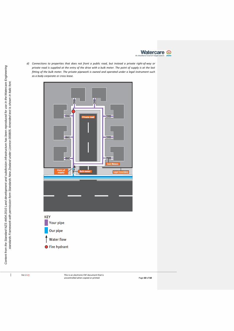
Ver.2.23 This is an electronic ESF document that is uncontrolled when copied or printed Page 60 of 60
Co
nte
nt
fro
m t
he
Sta
nd
ard
NZ
S 4
40
4:2
01
0 L
an
d d
eve
lop
me
nt
an
d s
ub
div
isio
n in
fra
str
uctu
re h
as b
ee
n r
ep
rod
uce
d f
or
use
in
th
e W
ate
rca
re E
ng
ine
eri
ng
sta
nd
ard
s F
ram
ew
ork
with
pe
rmis
sio
n f
orm
Sta
nd
ard
s N
ew
Ze
ala
nd
un
de
r L
ice
nce
00
08
05.
Am
en
de
d t
ext
is s
ho
wn
in
Ita
lic f
on
t.
d) Connections to properties that does not front a public road, but instead a private right-of-way or
private road is supplied at the entry of the drive with a bulk meter. The point of supply is at the last
fitting of the bulk meter. The private pipework is owned and operated under a legal instrument such
as a body corporate or cross lease.