Embed Size (px)
Citation preview

The Automotive-Grade DeviceHandbookAUT5V12017.02.13
SubscribeSend Feedback

Contents
1 Overview......................................................................................................................... 41.1 Intel Automotive-Grade Devices............................................................................... 41.2 Intel Automotive Qualifications................................................................................. 41.3 Supported Device Families....................................................................................... 4
2 Supported Automotive-Grade Devices..............................................................................62.1 Cyclone 10 Devices.................................................................................................6
2.1.1 Supported Automotive-Grade Devices............................................................62.1.2 Package Options and Maximum User I/Os...................................................... 72.1.3 Device Ordering Codes................................................................................ 7
2.2 Arria 10 Devices.....................................................................................................82.2.1 Supported Automotive-Grade Devices............................................................82.2.2 Package Options and Maximum User I/Os...................................................... 92.2.3 Device Ordering Codes................................................................................ 9
2.3 Enpirion Devices.....................................................................................................92.3.1 Supported Automotive-Grade Devices............................................................9
2.4 MAX 10 Devices....................................................................................................102.4.1 Supported Automotive-Grade Devices..........................................................102.4.2 Pacakge Options and Maximum User I/Os.................................................... 122.4.3 Device Ordering Codes.............................................................................. 13
2.5 Cyclone V SoC Devices.......................................................................................... 132.5.1 Supported Automotive-Grade Devices..........................................................132.5.2 Package Options and Maximum User I/Os.................................................... 142.5.3 Device Ordering Codes.............................................................................. 15
2.6 Cyclone V Devices.................................................................................................162.6.1 Supported Automotive-Grade Devices..........................................................162.6.2 Package Options and Maximum User I/Os.................................................... 162.6.3 Device Ordering Codes.............................................................................. 18
2.7 Cyclone IV Devices................................................................................................192.7.1 Supported Automotive-Grade Devices..........................................................192.7.2 Package Options and Maximum User I/Os.................................................... 202.7.3 Device Ordering Codes.............................................................................. 21
2.8 MAX V Devices..................................................................................................... 222.8.1 Supported Automotive-Grade Devices..........................................................222.8.2 Package Options and Maximum User I/Os.................................................... 222.8.3 Device Ordering Codes.............................................................................. 23
2.9 MAX II Devices.....................................................................................................232.9.1 Supported Automotive-Grade Devices..........................................................232.9.2 Device Ordering Codes.............................................................................. 24
2.10 Cyclone III Devices (Legacy Support).................................................................... 242.10.1 Supported Automotive-Grade Devices........................................................ 242.10.2 Device Ordering Codes.............................................................................25
2.11 Cyclone II Devices (Legacy Support)......................................................................252.11.1 Supported Automotive-Grade Devices........................................................ 252.11.2 Device Ordering Codes.............................................................................26
2.12 Cyclone Devices (Legacy Support).........................................................................262.12.1 Supported Automotive-Grade Devices........................................................ 26
Contents
The Automotive-Grade Device Handbook2

2.12.2 Device Ordering Codes.............................................................................262.13 MAX 7000A Devices (Legacy Support)....................................................................27
2.13.1 Supported Automotive-Grade Devices........................................................ 272.13.2 Device Ordering Codes.............................................................................27
3 Quartus Prime Software Support................................................................................... 28
4 Power Analysis and Estimation...................................................................................... 294.1 Early Power Estimator........................................................................................... 294.2 Power Analyzer.....................................................................................................29
5 DC and Timing Specifications......................................................................................... 31
6 Pin-Out Information.......................................................................................................32
7 Package and Board Layout Information......................................................................... 33
A Document Revision History for the Automotive-Grade Device Handbook....................... 34
Contents
The Automotive-Grade Device Handbook3

1 Overview
1.1 Intel Automotive-Grade Devices
Intel automotive-grade devices are available in CPLD, FPGA, system on a chip (SoC),and Enpirion® PowerSoC's. You can use these devices for high-temperatureenvironments, such as automotive driver assist, infotainment, and e-vehicle.
Related Links
Automotive page, Intel websiteProvides more information about Intel automotive solutions
1.2 Intel Automotive Qualifications
Intel automotive-grade devices comply to the following qualitfications:
• ISO-26262
• IEC-61508
• AEC-Q100
• ISO-9001
• TS-16949
• Electronic Industries Alliance (EIA)
• Joint Electron Device Engineering Council (JEDEC)
Related Links
Automotive Quality and Reliability page, Intel websiteProvides more information about the certificates.
1.3 Supported Device Families
Table 1. Intel Automotive-Grade Device Families
Category Product Family Quartus SoftwareSupport 1
Description
IC, FPGA Cyclone® 10 Version 17.1 and later Low-cost, low-power, feature-rich FPGAs
IC, FPGA Arria® 10 Version 14.0.2 and later High-performance, low-power 20 nm FPGAs with hardfloating-point digital signal processing (DSP) blocks
IC, power Enpirion — Integrated inductor, combination of small footprint, lownoise performance, and high efficiency
continued...
1 Starting from version 15.1, the Quartus II software is known as the Quartus® Prime software.
1 Overview
© 2017 Intel Corporation. All rights reserved. Intel, the Intel logo, Altera, Arria, Cyclone, Enpirion, MAX, NIOS,Quartus and Stratix words and logos are trademarks of Intel Corporation in the US and/or other countries.Other marks and brands may be claimed as the property of others. Intel warrants performance of its FPGA andsemiconductor products to current specifications in accordance with Intel's standard warranty, but reserves theright to make changes to any products and services at any time without notice. Intel assumes no responsibilityor liability arising out of the application or use of any information, product, or service described herein exceptas expressly agreed to in writing by Intel. Intel customers are advised to obtain the latest version of devicespecifications before relying on any published information and before placing orders for products or services.
ISO9001:2008Registered

Category Product Family Quartus SoftwareSupport 1
Description
IC, FPGA MAX® 10 Version 14.0.2 and later Low-cost, instant-on, small form factor programmablelogic device
IC, SoC Cyclone V SoC Version 12.1 and later Low-cost, low-power, user-customizable ARM-based SoCdevices
IC, FPGA Cyclone V Version 11.1 and later Low-cost, low-power, feature-rich 28 nm FPGAs
IC, FPGA Cyclone IV Version 9.1 SP2 and later Low-cost, low-power, feature-rich 60 nm FPGAs (1.2 V)
IC, CPLD MAX V Version 11.0 and later High-density, low-power glue logic CPLDs (1.8 V)
IC, CPLD MAX II Version 7.2 SP1 and later High-density, low-power glue logic CPLDs (3.3 V, 2.5 V)
Volume Production Support for Legacy Device Families
Category Product Family Quartus SoftwareSupport 2
Description
IC, FPGA Cyclone III Version 8.0 to 13.1 Low-cost, feature-rich 65 nm FPGAs
IC, FPGA Cyclone II Version 7.2 SP1 to 13.0 Low-cost, feature-rich 90 nm FPGAs
IC, FPGA Cyclone Version 7.2 SP1 to 13.0 Low-cost, glue logic 130 nm FPGAs
IC, CPLD MAX 7000AE Version 7.2 SP1 to 13.0 High-performance, glue logic CPLDs (5-V I/Ocompatible)
1 Starting from version 15.1, the Quartus II software is known as the Quartus® Prime software.
2 The legacy devices are only supported in the Quartus II software.
1 Overview
The Automotive-Grade Device Handbook5
2 Supported Automotive-Grade Devices
2.1 Cyclone 10 Devices
2.1.1 Supported Automotive-Grade Devices
Table 2. Automotive-Grade in Cyclone 10 DevicesOther automotive-grade product line/package combinations or ordering codes might be available upon request.Consult your Intel sales representative to submit your request.
Device OrderingCode
Device Package JunctionTemperature Range
Speed Grade
10CL006YE144A7G 10CL006 144-pin EQFP –40°C to 125°C –7
10CL006YU256A7G 10CL006 256-pin UBGA –40°C to 125°C –7
10CL010YE144A7G 10CL010 144-pin EQFP –40°C to 125°C –7
10CL010YM164A7G 10CL010 164-pin MBGA –40°C to 125°C –7
10CL010YU256A7G 10CL010 256-pin UBGA –40°C to 125°C –7
10CL016YE144A7G 10CL016 144-pin EQFP –40°C to 125°C –7
10CL016YM164A7G 10CL016 164-pin MBGA –40°C to 125°C –7
10CL016YU256A7G 10CL016 256-pin UBGA –40°C to 125°C –7
10CL025YE144A7G 10CL025 144-pin EQFP –40°C to 125°C –7
10CL025YU256A7G 10CL025 256-pin UBGA –40°C to 125°C –7
10CL025YU484A7G 10CL025 484-pin UBGA –40°C to 125°C –7
10CL040YU484A7G 10CL040 484-pin UBGA –40°C to 125°C –7
10CL055YU484A7G 10CL055 484-pin UBGA –40°C to 125°C –7
10CL080YU484A7G 10CL080 484-pin UBGA –40°C to 125°C –7
10CX085YU484A6G 10CX085 484-pin UBGA –40°C to 125°C –6
10CX105YU484A6G 10CX105 484-pin UBGA –40°C to 125°C –6
10CX150YF780A6G 10CX150 780-pin FBGA –40°C to 125°C –6
10CX150YU484A6G 10CX150 484-pin UBGA –40°C to 125°C –6
10CX220YF780A6G 10CX220 780-pin FBGA –40°C to 125°C –6
10CX220YU484A6G 10CX220 484-pin UBGA –40°C to 125°C –6
2 Supported Automotive-Grade Devices
© 2017 Intel Corporation. All rights reserved. Intel, the Intel logo, Altera, Arria, Cyclone, Enpirion, MAX, NIOS,Quartus and Stratix words and logos are trademarks of Intel Corporation in the US and/or other countries.Other marks and brands may be claimed as the property of others. Intel warrants performance of its FPGA andsemiconductor products to current specifications in accordance with Intel's standard warranty, but reserves theright to make changes to any products and services at any time without notice. Intel assumes no responsibilityor liability arising out of the application or use of any information, product, or service described herein exceptas expressly agreed to in writing by Intel. Intel customers are advised to obtain the latest version of devicespecifications before relying on any published information and before placing orders for products or services.
ISO9001:2008Registered

2.1.2 Package Options and Maximum User I/Os
Table 3. Package Options and Maximum User I/Os in Cyclone 10 LP Devices
PackageType/ Pin
Count
BallSpacing(mm)
Dimensions
(mm)
Product Line
10CL006 10CL010 10CL016 10CL025 10CL040 10CL055 10CL080
(6K LEs) (10KLEs)
(16KLEs)
(25KLEs)
(40KLEs)
(55KLEs)
(80KLEs)
GPIO / LVDS
MBGA-164 0.5 8 × 8 — 71 / 22 71 / 22 — — — —
UBGA-256 0.8 14 × 14 176 / 65 176 / 65 162 / 53 150 / 52 — — —
UBGA-484 0.8 19 × 19 — — — 325 / 124 325 / 124 321 / 132 289 / 110
EQFP-144 0.5 22 × 22 88 / 22 88 / 22 78 / 19 76 / 18 — — —
Table 4. Package Options and Maximum User I/Os in Cyclone 10 GX Devices
PackageType/ Pin
Count
Ball Spacing(mm)
Dimensions(mm)
Product Line
10CX085 10CX105 10CX150 10CX220
(85K LEs) (104K LEs) (150K LEs) (220K LEs)
GPIO / LVDS / XCVR
UBGA-484 0.8 19 × 19 188 / 70 / 4 188 / 72 / 4 188 / 72 / 6 188 / 72 / 6
FBGA-780 1 29 × 29 — — 284 / 118 / 12 284 / 118 / 12
2.1.3 Device Ordering Codes
Figure 1. Automotive-Grade Ordering Information for Cyclone 10 LP Devices
Family Signature
L : LP
10C : Cyclone 10
006 : 6,272 logic elements010 : 10,320 logic elements016 : 15,408 logic elements025 : 24,624 logic elements040 : 39,600 logic elements055 : 55,856 logic elements080 : 81,264 logic elements
Package TypeE : Enhance Thin Quad Flat Pack (EQFP)U : Ultra FineLine BGA (UBGA)M : Micro FineLine BGA (MBGA)
Operating TemperatureA : Automotive (TJ = -40°C to 125°C)
FPGA Fabric Speed Grade7Core Voltage
Y : Standard voltage (1.2 V)
10C L 080 UY 484 A 7
Member Code
Family Variant
Optional SuffixIndicates specific device options or shipment methodG : RoHS6-compliant packagingES : Engineering sample
GES
Package CodeEQFP Package Type144 : 144 pinsUBGA Package Type256 : 256 pins484 : 484 pins
MBGA Package Type164 : 164 pins
2 Supported Automotive-Grade Devices
The Automotive-Grade Device Handbook7

Figure 2. Automotive-Grade Ordering Information for Cyclone 10 GX Devices
Family Signature
Package Type
Package Code
Operating Temperature
FPGA Fabric Speed Grade
X : 10.3125 Gbps transceivers
10C : Cyclone 10
085 : 85K logic elements105 : 105K logic elements150 : 150K logic elements220 : 220K logic elements
Y : Standard (0.9 V)
F : FineLine BGA (FBGA)U : Ultra FineLine BGA (UBGA)
FBGA Package Type780 : 780 pinsUBGA Package Type484 : 484 pins
A : Automotive (TJ = -40°C to 125°C)
6
10C X 220 Y F 780 A 6
Logic Density
Family Variant
Core Voltage
Optional SuffixIndicates specific device options or shipment method
RoHSG : RoHS6-compliant
ES : Engineering sample
ESG
2.2 Arria 10 Devices
2.2.1 Supported Automotive-Grade Devices
Table 5. Automotive-Grade in Arria 10 DevicesOther automotive-grade product line/package combinations or ordering codes might be available upon request.Consult your Intel sales representative to submit your request.
Device OrderingCode
Device Package AmbientTemperature Range
Speed Grade
10AX016C4U19A3SG 10AX016 484-pin UBGA –40°C to 125°C –3
10AX022C4U19A3SG 10AX022 484-pin UBGA –40°C to 125°C –3
10AX016E4F29A3SG 10AX016 780-pin FBGA –40°C to 125°C –3
10AX022E4F29A3SG 10AX022 780-pin FBGA –40°C to 125°C –3
10AX027E4F29A3SG 10AX027 780-pin FBGA –40°C to 125°C –3
10AX032E4F29A3SG 10AX032 780-pin FBGA –40°C to 125°C –3
10AX048E4F29A3SG 10AX048 780-pin FBGA –40°C to 125°C –3
10AX027H4F34A3SG 10AX027 1152-pin FBGA –40°C to 125°C –3
10AX032H4F34A3SG 10AX032 1152-pin FBGA –40°C to 125°C –3
10AX048H4F34A3SG 10AX048 1152-pin FBGA –40°C to 125°C –3
10AX057H4F34A3SG 10AX057 1152-pin FBGA –40°C to 125°C –3
10AX066H4F34A3SG 10AX066 1152-pin FBGA –40°C to 125°C –3
2 Supported Automotive-Grade Devices
The Automotive-Grade Device Handbook8

2.2.2 Package Options and Maximum User I/Os
Table 6. Package Options and Maximum User I/Os in Arria 10 GX Devices
PackageType/ Pin
Count
BallSpacin
g(mm)
Dimensions
(mm)
Product Line
10AX016 10AX022 10AX027 10AX032 10AX048 10AX057 10AX066
(160KLEs)
(220KLEs)
(270KLEs)
(320KLEs)
(480KLEs)
(570KLEs)
(660KLEs)
3 V I/O / LVDS I/O / XCVR
UBGA-484 0.8 19 × 19 48 / 192 /6
48 / 192 /6
— — — — —
FBGA-780 1 29 × 29 48 / 240 /12
48 / 240 /12
48 / 312 /12
48 / 312 /12
48 / 312 /12
— —
FBGA-1152 1 35 × 35 — — 48 / 336 /24
48 / 336 /24
48 / 444 /24
48 / 444 /24
48 / 444 /24
2.2.3 Device Ordering Codes
Figure 3. Automotive-Grade Ordering Information for Arria 10 GX Devices
Family Signature
Transceiver Count
TransceiverSpeed Grade
Package Type
Package Code
Operating Temperature
FPGA Fabric Speed Grade
Optional SuffixIndicates specific device options or shipment method
X : GX variant 17.4 Gbps transceivers
10A : Arria 10
016 : 160K logic elements022 : 220K logic elements027 : 270K logic elements032 : 320K logic elements048 : 480K logic elements057 : 570K logic elements066 : 660K logic elements
C : 6E : 12H : 24
4
F : FineLine BGA (FBGA), 1.0 mm pitchU : Ultra FineLine BGA (UBGA), 0.8 mm pitch
FBGA Package Type29 : 780 pins, 29 mm x 29 mm34 : 1,152 pins, 35 mm x 35 mm
UBGA Package Type19 : 484 pins, 19 mm x 19 mm
A : Automotive (TJ = -40° C to 100° C)
3
Power OptionS : Standard
RoHSG : RoHS6 ES : Engineering sample
10A X F066 H 4 S34 A 3 ESG
Logic Density
Family Variant
2.3 Enpirion Devices
2.3.1 Supported Automotive-Grade Devices
Table 7. Automotive-Grade in Enpirion DevicesOther automotive-grade product line/package combinations or ordering codes might be available upon request.Consult your Intel sales representative to submit your request.
2 Supported Automotive-Grade Devices
The Automotive-Grade Device Handbook9

Device Ordering Code Device Package Ambient TemperatureRange
EP5358HUA EP5358HUA 16-pin QFN –40°C to 105°C
EP5358LUA EP5358LUA 16-pin QFN –40°C to 105°C
EN6310QA EN6310QA 30-pin QFN –40°C to 105°C
EP53A8HQA EP53A8HQA 16-pin QFN –40°C to 105°C
EP53A8LQA EP53A8LQA 16-pin QFN –40°C to 105°C
EN6337QA EN6337QA 38-pin QFN –40°C to 105°C
EN6347QA EN6347QA 38-pin QFN –40°C to 105°C
EN6360QA EN6360QA 68-pin QFN –40°C to 105°C
EN63A0QA EN63A0QA 76-pin QFN –40°C to 105°C
2.4 MAX 10 Devices
2.4.1 Supported Automotive-Grade Devices
Table 8. Automotive-Grade in MAX 10 Devices
Device OrderingCode
Device Package JunctionTemperature Range
Speed Grade
10M02SCE144A7G 10M02SC 144-pin EQFP –40°C to 125°C –7
10M02SCM153A7G 3 10M02SC 153-pin MBGA –40°C to 125°C –7
10M02SCU169A7G 10M02SC 169-pin UBGA –40°C to 125°C –7
10M02DCU324A7G 10M02DC 324-pin UBGA –40°C to 125°C –7
10M02DCV36A7G 3 10M02DC 36-pin WLCSP –40°C to 125°C –7
10M04SCE144A7G 10M04SC 144-pin EQFP –40°C to 125°C –7
10M04SCM153A7G 3 10M04SC 153-pin MBGA –40°C to 125°C –7
10M04SCU169A7G 10M04SC 169-pin UBGA –40°C to 125°C –7
10M04DCF256A7G 10M04DC 256-pin FBGA –40°C to 125°C –7
10M04DAF256A7G 3 10M04DA 256-pin FBGA –40°C to 125°C –7
10M04DCU324A7G 10M04DC 324-pin UBGA –40°C to 125°C –7
10M04DAU324A7G 3 10M04DA 324-pin UBGA –40°C to 125°C –7
10M08DCV81A7G 3 10M08DC 81-pin WLCSP –40°C to 125°C –7
10M08DFV81A7G 3 10M08DF 81-pin WLCSP –40°C to 125°C –7
10M08SAU169A7G 3 10M08SA 169-pin UBGA –40°C to 125°C –7
10M08SCE144A7G 10M08SC 144-pin EQFP –40°C to 125°C –7
10M08SCM153A7G 3 10M08SC 153-pin MBGA –40°C to 125°C –7
continued...
3 This automotive-grade ordering code might be available upon request. Faster speed gradedevices might be available depending on the application and device feature needed. Consultyour Intel sales representative to submit your request.
2 Supported Automotive-Grade Devices
The Automotive-Grade Device Handbook10

Device OrderingCode
Device Package JunctionTemperature Range
Speed Grade
10M08SCU169A7G 10M08SC 169-pin UBGA –40°C to 125°C –7
10M08DCF256A7G 10M08DC 256-pin FBGA –40°C to 125°C –7
10M08DAF256A7G 3 10M08DA 256-pin FBGA –40°C to 125°C –7
10M08DCU324A7G 10M08DC 324-pin UBGA –40°C to 125°C –7
10M08DAU324A7G 3 10M08DA 324-pin UBGA –40°C to 125°C –7
10M08DCF484A7G 3 10M08DC 484-pin FBGA –40°C to 125°C –7
10M08DAF484A7G 3 10M08DA 484-pin FBGA –40°C to 125°C –7
10M16SCE144A7G 10M16SC 144-pin EQFP –40°C to 125°C –7
10M16SCU169A7G 10M16SC 169-pin UBGA –40°C to 125°C –7
10M16DCF256A7G 10M16DC 256-pin FBGA –40°C to 125°C –7
10M16DAF256A7G 3 10M16DA 256-pin FBGA –40°C to 125°C –7
10M16DCU324A7G 10M16DC 324-pin UBGA –40°C to 125°C –7
10M16DAU324A7G 3 10M16DA 324-pin UBGA –40°C to 125°C –7
10M16DCF484A7G 10M16DC 484-pin FBGA –40°C to 125°C –7
10M16DAF484A7G 3 10M16DA 484-pin FBGA –40°C to 125°C –7
10M25SCE144A7G 10M25SC 144-pin EQFP –40°C to 125°C –7
10M25DCF256A7G 10M25DC 256-pin FBGA –40°C to 125°C –7
10M25DAF256A7G 3 10M25DA 256-pin FBGA –40°C to 125°C –7
10M25DCF484A7G 3 10M25DC 484-pin FBGA –40°C to 125°C –7
10M25DAF484A7G 3 10M25DA 484-pin FBGA –40°C to 125°C –7
10M25DCF672A7G 3 10M25DC 672-pin FBGA –40°C to 125°C –7
10M25DAF672A7G 3 10M25DA 672-pin FBGA –40°C to 125°C –7
10M40SCE144A7G 10M40SC 144-pin EQFP –40°C to 125°C –7
10M40DCF256A7G 10M40DC 256-pin FBGA –40°C to 125°C –7
10M40DAF256A7G 3 10M40DA 256-pin FBGA –40°C to 125°C –7
10M40DCF484A7G 3 10M40DC 484-pin FBGA –40°C to 125°C –7
10M40DAF484A7G 3 10M40DA 484-pin FBGA –40°C to 125°C –7
10M40DCF672A7G 3 10M40DC 672-pin FBGA –40°C to 125°C –7
10M40DAF672A7G 3 10M40DA 672-pin FBGA –40°C to 125°C –7
10M50SCE144A7G 10M50SC 144-pin EQFP –40°C to 125°C –7
10M50DCF256A7G 10M50DC 256-pin FBGA –40°C to 125°C –7
10M50DAF256A7G 3 10M50DF 256-pin FBGA –40°C to 125°C –7
10M50DCF484A7G 3 10M50DC 484-pin FBGA –40°C to 125°C –7
10M50DAF484A7G 3 10M50DA 484-pin FBGA –40°C to 125°C –7
10M50DCF672A7G 3 10M50DC 672-pin FBGA –40°C to 125°C –7
10M50DAF672A7G 3 10M50DA 672-pin FBGA –40°C to 125°C –7
2 Supported Automotive-Grade Devices
The Automotive-Grade Device Handbook11

2.4.2 Pacakge Options and Maximum User I/Os
Table 9. Package Options and Maximum User I/Os in MAX 10 Single Power SupplyDevices
Device Package
Type M153153-pin MBGA
U169169-pin UBGA
E144144-pin EQFP
Size 8 mm × 8 mm 11 mm × 11 mm 22 mm × 22 mm
Ball Pitch 0.5 mm 0.8 mm 0.5 mm
10M02S 112 130 101
10M04S 112 130 101
10M08S 112 130 101
10M16S — 130 101
10M25S — — 101
10M40S — — 101
10M50S — — 101
Table 10. Package Options and Maximum User I/Os in MAX 10 Dual Power SupplyDevices
Device Package
Type V3636-pinWLCSP
V8181-pinWLCSP
U324324-pinUBGA
F256256-pinFBGA
F484484-pinFBGA
F672672-pinFBGA
Size 3 mm × 3mm
4 mm × 4mm
15 mm × 15mm
17 mm × 17mm
23 mm × 23mm
27 mm × 27mm
BallPitch
0.4 mm 0.4 mm 0.8 mm 1.0 mm 1.0 mm 1.0 mm
10M02D 27 — 160 — — —
10M04D — — 246 178 — —
10M08D — 56 246 178 250 —
10M16D — — 246 178 320 —
10M25D — — — 178 360 —
10M40D — — — 178 360 500
10M50D — — — 178 360 500
2 Supported Automotive-Grade Devices
The Automotive-Grade Device Handbook12

2.4.3 Device Ordering Codes
Figure 4. Automotive-Grade Ordering Information for MAX 10 Devices
Family Signature
Package Type
Package Code
Operating Temperature
FPGA Fabric Speed Grade
Optional SuffixIndicates specific device options or shipment method
10M : MAX 10
V : Wafer-Level Chip Scale (WLCSP)E : Plastic Enhanced Quad Flat Pack (EQFP)M : Micro FineLine BGA (MBGA)U : Ultra FineLine BGA (UBGA)F : FineLine BGA (FBGA)
3681
A : Automotive (TJ = -40° C to 125° C)
7
G : RoHS6
10M 16 DC F 256 A 7 G
Member Code
36 pins, 3 mm x 3 mm81 pins, 4 mm x 4 mm
::
2K logic elements4K logic elements8K logic elements16K logic elements25K logic elements40K logic elements50K logic elements
02: 04: 08: 16: 25:40:50:
WLCSP Package Type
144 144 pins, 20 mm x 20 mm:EQFP Package Type
153 153 pins, 8 mm x 8 mm:MBGA Package Type
169324
169 pins, 11 mm x 11 mm324 pins, 15 mm x 15 mm
::
UBGA Package Type
FBGA Package Type256484672
256 pins, 17 mm x 17 mm484 pins, 23 mm x 23 mm672 pins, 27 mm x 27 mm
:::
SC : Single supply - compact features :
:
::
SA : Single supply - analog and flash features with RSU option
DC Dual supply - compact featuresDF Dual supply - flash features with RSU optionDA Dual supply - analog and flash features
with RSU option
Feature Options
2.5 Cyclone V SoC Devices
2.5.1 Supported Automotive-Grade Devices
Table 11. Automotive-Grade in Cyclone V SoC DevicesOther automotive-grade product line/package combinations or ordering codes might be available upon request.Consult your Intel sales representative to submit your request.
Device OrderingCode
Device Package JunctionTemperature Range
Speed Grade
5CSEBA2U19A7N 5CSEBA2 484-pin UBGA –40°C to 125°C –7
5CSEBA2U23A7N 5CSEBA2 672-pin UBGA –40°C to 125°C –7
5CSEMA2U23A7N 5CSEMA2 672-pin UBGA –40°C to 125°C –7
5CSEBA4U19A7N 5CSEBA4 484-pin UBGA –40°C to 125°C –7
5CSEBA4U23A7N 5CSEBA4 672-pin UBGA –40°C to 125°C –7
5CSEMA4U23A7N 5CSEMA4 672-pin UBGA –40°C to 125°C –7
5CSEBA5U19A7N 5CSEBA5 484-pin UBGA –40°C to 125°C –7
continued...
2 Supported Automotive-Grade Devices
The Automotive-Grade Device Handbook13

Device OrderingCode
Device Package JunctionTemperature Range
Speed Grade
5CSEBA5U23A7N 5CSEBA5 672-pin UBGA –40°C to 125°C –7
5CSEMA5U23A7N 5CSEMA5 672-pin UBGA –40°C to 125°C –7
5CSEMA5F31A7N 5CSEMA5 896-pin FBGA –40°C to 125°C –7
5CSEBA6U19A7N 5CSEBA6 484-pin UBGA –40°C to 125°C –7
5CSEBA6U23A7N 5CSEBA6 672-pin UBGA –40°C to 125°C –7
5CSEMA6U23A7N 5CSEMA6 672-pin UBGA –40°C to 125°C –7
5CSEMA6F31A7N 5CSEMA6 896-pin FBGA –40°C to 125°C –7
5CSXFC2C6U23A7N 5CSXFC2 672-pin UBGA –40°C to 125°C –7
5CSXFC4C6U23A7N 5CSXFC4 672-pin UBGA –40°C to 125°C –7
5CSXFC5C6U23A7N 5CSXFC5 672-pin UBGA –40°C to 125°C –7
5CSXFC6C6U23A7N 5CSXFC6 672-pin UBGA –40°C to 125°C –7
5CSXFC6D6F31A7N 5CSXFC6 896-pin FBGA –40°C to 125°C –7
2.5.2 Package Options and Maximum User I/Os
Table 12. Package Options and Maximum User I/Os in Cyclone V SE Devices
PackageType/ Pin
Count
Ball Spacing(mm)
Dimensions(mm)
Product Line
5CSEA2 5CSEA4 5CSEA5 5CSEA6
(25K LEs) (40K LEs) (85K LEs) (110K LEs)
FPGA I/Os / HPS I/Os
UBGA-484 0.8 19 x 19 66 / 151 4 66 / 151 4 66 / 151 4 66 / 151 4
UBGA-672 0.8 23 x 23 145 / 181 4 145 / 181 4 145 / 181 4 145 / 181 4
FBGA-896 1 31 x 31 — — 288 / 181 4 288 / 181 4
Table 13. Package Options and Maximum User I/Os in Cyclone V SX Devices
PackageType/ Pin
Count
Ball Spacing(mm)
Dimensions(mm)
Product Line
5CSXC2 5CSXC4 5CSXC5 5CSXC6
(25K LEs) (40K LEs) (85K LEs) (110K LEs)
FPGA I/Os / HPS I/Os / XCVRs
UBGA-672 0.8 23 x 23 145 / 181 / 6 4 145 / 181 / 6 4 145 / 181 / 6 4 145 / 181 / 6 4
FBGA-896 1 31 x 31 — — 288 / 181 / 9 5 288 / 181 / 9 4
4 Package options available with automotive-grade variants.
5 This automotive-grade ordering code might be available upon request. Faster speed gradedevices might be available depending on the application and device feature needed. Consultyour Intel sales representative to submit your request.
2 Supported Automotive-Grade Devices
The Automotive-Grade Device Handbook14

2.5.3 Device Ordering Codes
Figure 5. Automotive-Grade Ordering Information for Cyclone V SE Devices
Family Signature
Embedded Hard IPs (*)
Package Type
Package Code
Operating Temperature
FPGA FabricSpeed Grade
Optional SuffixIndicates specific device options or shipment method
SE : SoC device with enhanced logic/memory
5C : Cyclone V
F : FineLine BGA (FBGA)U : Ultra FineLine BGA (UBGA)
FBGA Package Type31 : 896 pinsUBGA Package Type19 : 484 pins23 : 672 pins
A : Automotive (TJ = -40° C to 125° C)
7
Processor CoresOmit for dual-coreS : Single-core
N : Lead-free packaging
5C SE M A6 F 31 A 7 S N
Member Code
Family Variant
A2 : 25K logic elementsA4 : 40K logic elementsA5 : 85K logic elementsA6 : 110K logic elements
B : No hard PCIe or hard memory controller
M : No hard PCIe and 1 hard memory controller in the FPGA
Note:* All Cyclone V SoC devices include one hard memory controller dedicated to the processor and which can be shared by the FPGA.
Figure 6. Automotive-Grade Ordering Information for Cyclone V SX Devices
Family Signature
Embedded Hard IPs (*)
Transceiver Count
TransceiverSpeed Grade
Package Type
Package Code
Operating Temperature
FPGA FabricSpeed Grade
Optional SuffixIndicates specific device options or shipment method
SX : SoC device with 3-Gbps transceivers
F : Maximum 2 hard PCIe controllers and 1 hard memory controller in the FPGA
5C : Cyclone V
C2 : 25K logic elementsC4 : 40K logic elementsC5 : 85K logic elementsC6 : 110K logic elements
C : 6D : 9
6 : 3.125 Gbps
F : FineLine BGA (FBGA)U : Ultra FineLine BGA (UBGA)
FBGA Package Type31 : 896 pinsUBGA Package Type23 : 672 pins
A : Automotive (TJ = -40° C to 125° C)
7
N : Lead-free packaging
5C SX F C6 C 6 U 23 A 7 N
Member Code
Family Variant
Note:* All Cyclone V SoC devices include one hard memory controller dedicated to the processor and which can be shared by the FPGA.
2 Supported Automotive-Grade Devices
The Automotive-Grade Device Handbook15

2.6 Cyclone V Devices
2.6.1 Supported Automotive-Grade Devices
Table 14. Automotive-Grade in Cyclone V DevicesOther automotive-grade product line/package combinations or ordering codes might be available upon request.Consult your Intel sales representative to submit your request.
Device OrderingCode
Device Package JunctionTemperature Range
Speed Grade
5CEBA2F17A7N 5CEBA2 256-pin FBGA –40°C to 125°C –7
5CEFA2U19A7N 5CEFA2 484-pin UBGA –40°C to 125°C –7
5CEBA4F17A7N 5CEBA4 256-pin FBGA –40°C to 125°C –7
5CEFA4U19A7N 5CEFA4 484-pin UBGA –40°C to 125°C –7
5CEFA5U19A7N 5CEFA5 484-pin UBGA –40°C to 125°C –7
5CEFA7U19A7N 5CEFA7 484-pin UBGA –40°C to 125°C –7
5CEFA9U19A7N 5CEFA9 484-pin UBGA –40°C to 125°C –7
5CGXFC3B6U15A7N 5CGXFC3 324-pin UBGA –40°C to 125°C –7
5CGXFC3B6U19A7N 5CGXFC3 484-pin UBGA –40°C to 125°C –7
5CGXFC4C6U19A7N 5CGXFC4 484-pin UBGA –40°C to 125°C –7
5CGXFC5C6U19A7N 5CGXFC5 484-pin UBGA –40°C to 125°C –7
5CGXFC5C6F23A7N 5CGXFC5 484-pin FBGA –40°C to 125°C –7
5CGXFC7C6U19A7N 5CGXFC7 484-pin UBGA –40°C to 125°C –7
5CGXFC9A6U19A7N 5CGXFC9 484-pin UBGA –40°C to 125°C –7
5CGTFD5C5U19A7N 5CGTFD5 484-pin UBGA –40°C to 125°C –7
5CGTFD7C5U19A7N 5CGTFD7 484-pin UBGA –40°C to 125°C –7
5CGTFD9A5U19A7N 5CGTFD9 484-pin UBGA –40°C to 125°C –7
2.6.2 Package Options and Maximum User I/Os
Table 15. Package Options and Maximum User I/Os in Cyclone V E Devices
PackageType/ Pin
Count
BallSpacing(mm)
Dimensions(mm)
Product Line
5CEA2 5CEA4 5CEA5 5CEA7 5CEA9
(25K LEs) (49K LEs) (77K LEs) (149.5KLEs)
(301K LEs)
I/Os
FBGA-256 1 17 x 17 128 6 128 6 — — —
UBGA-324 0.8 15 x 15 176 7 176 7 — — —
continued...
6 Package options available with automotive-grade variants.
2 Supported Automotive-Grade Devices
The Automotive-Grade Device Handbook16

PackageType/ Pin
Count
BallSpacing(mm)
Dimensions(mm)
Product Line
5CEA2 5CEA4 5CEA5 5CEA7 5CEA9
(25K LEs) (49K LEs) (77K LEs) (149.5KLEs)
(301K LEs)
I/Os
UBGA-484 0.8 19 x 19 224 6 224 6 224 6 240 6 —
FBGA-484 1 23 x 23 224 7 224 7 240 7 240 7 224 7
FBGA-672 1 27 x 27 — — — 336 7 336 7
FBGA-896 1 31 x 31 — — — 480 7 480 7
Table 16. Package Options and Maximum User I/Os in Cyclone V GX Devices
PackageType/ Pin
Count
BallSpacing(mm)
Dimensions(mm)
Product Line
5CGXC3 5CGXC4 5CGXC5 5CGXC7 5CGXC9
(36K LEs) (50K LEs) (77K LEs) (149.5KLEs)
(301K LEs)
I/Os / XCVRs
UBGA-324 0.8 15 x 15 144 / 3 6 — — — —
UBGA-484 0.8 19 x 19 208 / 3 6 224 / 6 6 224 / 6 6 240 / 6 6 240 / 5 6
FBGA-484 1 23 x 23 208 / 3 7 240 / 6 7 240 / 6 6 240 / 6 7 224 / 6 7
FBGA-672 1 27 x 27 — 336 / 6 7 336 / 6 7 336 / 9 7 336 / 9 7
FBGA-896 1 31 x 31 — — — 480 / 9 7 480 / 12 7
FBGA-1152 1 35 x 35 — — — — 560 / 12 7
Table 17. Package Options and Maximum User I/Os in Cyclone V GT Devices
Package Type/Pin Count
Ball Spacing(mm)
Dimensions(mm)
Product Line
5CGTD5 5CGTD7 5CGTD9
(77K LEs) (149.5K LEs) (301K LEs)
I/Os / XCVRs
UBGA-484 0.8 19 x 19 224 / 6 6 240 / 6 6 240 / 5 6
FBGA-484 1 23 x 23 240 / 6 7 240 / 6 7 224 / 6 7
FBGA-672 1 27 x 27 336 / 6 7 336 / 9 7 336 / 9 7
FBGA-896 1 31 x 31 — 480 / 9 7 480 / 12 7
FBGA-1152 1 35 x 35 — — 560 / 12 7
7 These package options are not currently available in automotive-grade but might becomeavailable upon request. Consult your Intel sales representative to submit your request.
2 Supported Automotive-Grade Devices
The Automotive-Grade Device Handbook17

2.6.3 Device Ordering Codes
Figure 7. Automotive-Grade Ordering Information for Cyclone V E Devices
Family Signature
Embedded Hard IPs
Package Type
Package Code
Operating Temperature
FPGA Fabric Speed Grade
Optional SuffixIndicates specific device options or shipment method
E : Enhanced logic/memory
F : No hard PCIe and maximum 2 hard memory controllers
5C : Cyclone V
F : FineLine BGA (FBGA) U : Ultra FineLine BGA (UBGA)
FBGA Package Type17 : 256 pins23 : 484 pins27 : 672 pins31 : 896 pinsUBGA Package Type15 : 324 pins19 : 484 pins
A : Automotive (TJ = -40° C to 125° C)
7
N : Lead-free packaging
5C E F A9 F 31 C 7 N
Member Code
Family Variant
A2 : 25K logic elements A4 : 49K logic elementsA5 : 77K logic elementsA7 : 149.5K logic elementsA9 : 301K logic elements
Figure 8. Automotive-Grade Ordering Information for Cyclone V GX Devices
Family Signature
Embedded Hard IPs
Transceiver Count
TransceiverSpeed Grade
Package Type
Package Code
Operating Temperature
FPGA Fabric Speed Grade
Optional SuffixIndicates specific device options or shipment methodGX : 3-Gbps transceivers
F : Maximum 2 hard PCIe and maximum 2 hard memory controllers
5C : Cyclone V
C3 : 31.5K logic elementsC4 : 50K logic elementsC5 : 77K logic elementsC7 : 149.5K logic elementsC9 : 301K logic elements
B : 3A : 5C : 6
6 : 3.125 Gbps
F : FineLine BGA (FBGA)U : Ultra FineLine BGA (UBGA)
FBGA Package Type23 : 484 pins27 : 672 pins31 : 896 pins35 : 1,152 pinsUBGA Package Type15 : 324 pins19 : 484 pins
A : Automotive (TJ = -40° C to 125° C)
7
N : Lead-free packaging
5C GX F C7 C 6 U 19 A 7 N
Member Code
Family Variant
2 Supported Automotive-Grade Devices
The Automotive-Grade Device Handbook18

Figure 9. Automotive-Grade Ordering Information for Cyclone V GT Devices
Family Signature
Embedded Hard IPs
Transceiver Count
Transceiver Speed Grade
Package Type
Package Code
Operating Temperature
FPGA FabricSpeed Grade
Optional SuffixIndicates specific device options or shipment methodGT : 5-Gbps transceivers
F : 2 hard PCIe and 2 hard memory controllers
5C : Cyclone V
D5 : 77K logic elementsD7 : 149.5K logic elementsD9 : 301K logic elements
A : 5C : 6
5 : 5 Gbps
F : FineLine BGA (FBGA)U : Ultra FineLine BGA (UBGA)
FBGA Package Type23 : 484 pins27 : 672 pins31 : 896 pins35 : 1,152 pinsUBGA Package Type19 : 484 pins
A : Automotive (TJ = -40° C to 125° C)
7
N : Lead-free packaging
5C GT F D7 C 5 U 19 A 7 N
Member Code
Family Variant
2.7 Cyclone IV Devices
2.7.1 Supported Automotive-Grade Devices
Table 18. Automotive-Grade in Cyclone IV DevicesOther automotive-grade product line/package combinations or ordering codes might be available upon request.Consult your Intel sales representative to submit your request.
Device OrderingCode
Device Package JunctionTemperature Range
Speed Grade
EP4CE6F17A7N EP4CE6 256-pin FBGA –40°C to 125°C –7
EP4CE6E22A7N EP4CE6 144-pin EQFP –40°C to 125°C –7
EP4CE10F17A7N EP4CE10 256-pin FBGA –40°C to 125°C –7
EP4CE10E22A7N EP4CE10 144-pin EQFP –40°C to 125°C –7
EP4CE15F17A7N EP4CE15 256-pin FBGA –40°C to 125°C –7
EP4CE15F23A7N EP4CE15 484-pin FBGA –40°C to 125°C –7
EP4CE15U14A7N EP4CE15 256-pin UBGA –40°C to 125°C –7
EP4CE22F17A7N EP4CE22 256-pin FBGA –40°C to 125°C –7
EP4CE22E22A7N EP4CE22 144-pin EQFP –40°C to 125°C –7
EP4CE22U14A7N EP4CE22 256-pin UBGA –40°C to 125°C –7
EP4CE30F19A7N EP4CE30 324-pin FBGA –40°C to 125°C –7
EP4CE30F23A7N EP4CE30 484-pin FBGA –40°C to 125°C –7
EP4CE40F19A7N EP4CE40 324-pin FBGA –40°C to 125°C –7
EP4CE40F23A7N EP4CE40 484-pin FBGA –40°C to 125°C –7
continued...
2 Supported Automotive-Grade Devices
The Automotive-Grade Device Handbook19
Device OrderingCode
Device Package JunctionTemperature Range
Speed Grade
EP4CE40U19A7N EP4CE40 484-pin UBGA –40°C to 125°C –7
EP4CE55F23A7N EP4CE55 484-pin FBGA –40°C to 125°C –7
EP4CGX15BF14A7N EP4CGX15 169-pin FBGA –40°C to 125°C –7
2.7.2 Package Options and Maximum User I/Os
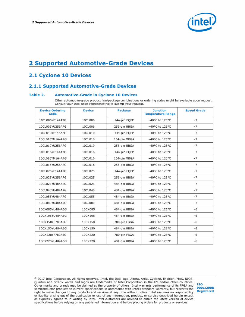
Table 19. Package Options and Maximum User I/Os in Cyclone IV E Devices
Package
Type/Pin
Count
BallSpacin
g(mm)
Dimensions(mm)
Product Line
EP4CE6
(6.3KLEs)
EP4CE10
(10.3KLEs)
EP4CE15
(15.4KLEs)
EP4CE22
(22.3KLEs)
EP4CE30
(28.8KLEs)
EP4CE40
(39.6KLEs)
EP4CE55
(55.9KLEs)
EP4CE75
(75.4KLEs)
EP4CE115
(114.5K LEs)
I/Os
EQFP-144
0.5 22 x 22 91 8 91 8 81 9 79 8 — — — — —
MBGA-164
0.5 8 x 8 — — 89 9 — — — — — —
UBGA-256
0.8 14 x 14 179 9 179 9 165 9 153 9 — — — — —
FBGA-256
1 17 x 17 179 8 179 8 165 8 153 8 — — — — —
UBGA-484
0.8 19 x 19 — — — — — 328 9 324 9 292 9 —
FBGA-324
1 19 x 19 — — — — 193 8 193 8 — — —
FBGA-484
1 23 x 23 — — 343 8 — 328 8 328 8 324 9 292 9 280 9
FBGA-780
1 29 x 29 — — — — 532 9 532 9 374 9 426 9 528 9
Table 20. Package Options and Maximum User I/Os in Cyclone IV GX Devices
PackageType/
PinCount
BallSpacing(mm)
Dimensions
(mm)
Product Line
EP4CGX15 (14.4K
LEs)
EP4CGX22 (21.3K
LEs)
EP4CGX30 (29.4K
LEs)
EP4CGX50 (49.9K
LEs)
EP4CGX75 (73.9K
LEs)
EP4CGX110
(109.4KLEs)
EP4CGX150
(149.8KLEs)
I/Os
QFN-148 0.5 11 x 11 72 / 2 9 — — — — — —
FBGA-169 1 14 x 14 72 / 2 8 72 / 2 9 72 / 2 9 — — — —
continued...
8 Package options available with automotive-grade variants.
9 These package options are not currently available in automotive-grade but might becomeavailable upon request. Consult your Intel sales representative to submit your request.
2 Supported Automotive-Grade Devices
The Automotive-Grade Device Handbook20

PackageType/
PinCount
BallSpacing(mm)
Dimensions
(mm)
Product Line
EP4CGX15 (14.4K
LEs)
EP4CGX22 (21.3K
LEs)
EP4CGX30 (29.4K
LEs)
EP4CGX50 (49.9K
LEs)
EP4CGX75 (73.9K
LEs)
EP4CGX110
(109.4KLEs)
EP4CGX150
(149.8KLEs)
I/Os
FBGA-324 1 19 x 19 — 150 / 4 9 150 / 4 9 — — — —
FBGA-484 1 23 x 23 — — 290 / 4 9 290 / 4 9 290 / 4 9 270 / 4 9 270 / 4 9
FBGA-672 1 27 x 27 — — — 310 / 8 9 310 / 8 9 393 / 8 9 393 / 8 9
FBGA-896 1 31 x 31 — — — — — 475 / 8 9 475 / 8 9
2.7.3 Device Ordering Codes
Figure 10. Automotive-Grade Ordering Information for Cyclone IV E Devices
Family Signature
Package Type
Package Code
Operating Temperature
Speed Grade
Optional SuffixIndicates specific device options or shipment method
E : Enhanced logic/memory
EP4C : Cyclone IV
6 : 6,272 logic elements10 : 10,320 logic elements15 : 15,408 logic elements22 : 22,320 logic elements30 : 28,848 logic elements40 : 39,600 logic elements55 : 55,856 logic elements
F : FineLine BGA (FBGA)E : Enhanced Thin Quad Flat Pack (EQFP)U : Ultra FineLine BGA (UBGA)
FBGA Package Type17 : 256 pins19 : 324 pins23 : 484 pinsEQFP Package Type22 : 144 pinsUBGA Package Type14 : 256 pins19 : 484 pins
A : Automotive temperature (TJ = -40° C to 125° C)
7
N : Lead-free packaging
EP4C E 40 F 23 A 7 N
Member Code
Family Variant
Figure 11. Automotive-Grade Ordering Information for Cyclone IV GX Devices
Family Signature
Transceiver Count
Package Type
Package Code
Operating Temperature
Speed Grade
Optional SuffixIndicates specific device options or shipment method
GX : 3-Gbps transceivers
EP4C : Cyclone IV
15 : 14,400 logic elements
B : 2
F : FineLine BGA (FBGA)
FBGA Package Type14 : 169 pins
A : Automotive temperature (TJ = -40° C to 125° C)
7
N : Lead-free packaging
EP4C GX 15 B F 14 A 7 N
Member Code
Family Variant
2 Supported Automotive-Grade Devices
The Automotive-Grade Device Handbook21

2.8 MAX V Devices
2.8.1 Supported Automotive-Grade Devices
Table 21. Automotive-Grade in MAX V DevicesOther automotive-grade product line/package combinations or ordering codes might be available upon request.Consult your Intel sales representative to submit your request.
Device OrderingCode
Device Package JunctionTemperature Range
Speed Grade
5M40ZE64A5N 5M40Z 64-pin EQFP –40°C to 125°C –5
5M80ZE64A5N 5M80Z 64-pin EQFP –40°C to 125°C –5
5M80ZT100A5N 5M80Z 100-pin TQFP –40°C to 125°C –5
5M160ZE64A5N 5M160Z 64-pin EQFP –40°C to 125°C –5
5M160ZT100A5N 5M160Z 100-pin TQFP –40°C to 125°C –5
5M240ZT100A5N 5M240Z 100-pin TQFP –40°C to 125°C –5
5M570ZT100A5N 5M570Z 100-pin TQFP –40°C to 125°C –5
5M1270ZF256A5N 5M1270Z 256-pin FBGA –40°C to 125°C –5
5M1270ZT144A5N 5M1270Z 144-pin TQFP –40°C to 125°C –5
2.8.2 Package Options and Maximum User I/Os
Table 22. Package Options and Maximum User I/Os in MAX V Devices
PackageType/
PinCount
BallSpacing(mm)
Dimensions
(mm)
Product Line
5M40Z(40KLEs)
5M80Z(80KLEs)
5M160Z(160KLEs)
5M240Z(240KLEs)
5M570Z(570KLEs)
5M1270Z
(1270KLEs)
5M2210Z
(2210KLEs)
I/Os
MBGA-64 0.5 4.5 x 4.5 30 10 30 10 — — — — —
EQFP-64 0.5 7 x 7 54 11 54 11 54 11 — — — —
MBGA-68 0.5 5 x 5 — 52 10 52 10 52 10 — — —
QFP-100 0.5 14 x 14 — 79 11 79 11 79 11 74 11 — —
MBGA-100
0.5 6 x 6 — — 79 10 79 10 74 10 — —
DFP-144 0.5 20 x 20 — — — 114 10 114 10 114 11 —
FBGA-256 1 17 x 17 — — — — 159 10 211 11 203 10
FBGA-324 1 19 x 19 — — — — — 271 10 271 10
10 These package options are not currently available in automotive-grade but might becomeavailable upon request. Consult your Intel sales representative to submit your request.
11 Package options available with automotive-grade variants.
2 Supported Automotive-Grade Devices
The Automotive-Grade Device Handbook22
2.8.3 Device Ordering Codes
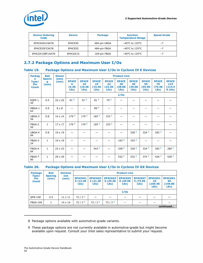
Figure 12. Automotive-Grade Ordering Information for MAX V Devices
Package Type
T: Thin quad flat pack (TQFP) F: FineLine BGA (FBGA) E: Plastic Enhanced Quad Flat Pack (EQFP)
Speed Grade
Family Signature
5M: MAX V
Operating Temperature
Pin Count
Device Type
40Z: 40 Logic Elements 80Z: 80 Logic Elements 160Z: 160 Logic Elements 240Z: 240 Logic Elements 570Z: 570 Logic Elements 1270Z: 1,270 Logic Elements
Optional Suffix
5
Number of pins for a particular package
5M 40Z E 64 A 5 N
A: Automotive temperature (TJ = -40° C to 125° C)
Indicates specific device options or shipment method N: Lead-free packaging
2.9 MAX II Devices
2.9.1 Supported Automotive-Grade Devices
Table 23. Automotive-Grade in MAX II DevicesOther automotive-grade product line/package combinations or ordering codes might be available upon request.Consult your Intel sales representative to submit your request.
Device OrderingCode
Device Package JunctionTemperature Range
Speed Grade
EPM240T100A5N EPM240 100-pin TQFP –40°C to 125°C –5
EPM570F100A5N EPM570 100-pin FBGA –40°C to 125°C –5
EPM570T100A5N EPM570 100-pin TQFP –40°C to 125°C –5
EPM570T144A5N EPM570 144-pin TQFP –40°C to 125°C –5
EPM1270T144A5N EPM1270 144-pin TQFP –40°C to 125°C –5
EPM1270F256A5N EPM1270 256-pin FBGA –40°C to 125°C –5
EPM2210F256A5N EPM2210 256-pin FBGA –40°C to 125°C –5
EPM2210F324A5N EPM2210 324-pin FBGA –40°C to 125°C –5
2 Supported Automotive-Grade Devices
The Automotive-Grade Device Handbook23

2.9.2 Device Ordering Codes
Figure 13. Automotive-Grade Ordering Information for MAX II Devices
Package Type
T:F:
Thin Quad Flat Pack (TQFP)FineLine BGA (FBGA)
240:570:
1270:2210:
Speed Grade
Family Signature
EPM: MAX II
Operating Temperature
Pin Count
Device Type
240 Logic Elements570 Logic Elements1,270 Logic Elements2,210 Logic Elements
Optional Suffix
Indicates specific device options or shipment method
Number of pins for a particular package
A: Automotive Temperature (T J = –40°C to 125°C)
EPM 240 T 100 A 5 N
N: Lead-Free Device
5
2.10 Cyclone III Devices (Legacy Support)
2.10.1 Supported Automotive-Grade Devices
Table 24. Automotive-Grade in Cyclone III Devices
Device OrderingCode
Device Package JunctionTemperature Range
Speed Grade
EP3C5E144A7N EP3C5 144-pin EQFP –40°C to 125°C –7
EP3C5F256A7N EP3C5 256-pin FBGA –40°C to 125°C –7
EP3C5U256A7N EP3C5 256-pin UBGA –40°C to 125°C –7
EP3C10E144A7N EP3C10 144-pin EQFP –40°C to 125°C –7
EP3C10F256A7N EP3C10 256-pin FBGA –40°C to 125°C –7
EP3C10U256A7N EP3C10 256-pin UBGA –40°C to 125°C –7
EP3C16E144A7N EP3C16 144-pin EQFP –40°C to 125°C –7
EP3C16F256A7N EP3C16 256-pin FBGA –40°C to 125°C –7
EP3C16U256A7N EP3C16 256-pin UBGA –40°C to 125°C –7
EP3C16F484A7N EP3C16 484-pin FBGA –40°C to 125°C –7
EP3C16U484A7N EP3C16 484-pin UBGA –40°C to 125°C –7
EP3C25E144A7N EP3C25 144-pin EQFP –40°C to 125°C –7
EP3C25F256A7N EP3C25 256-pin FBGA –40°C to 125°C –7
EP3C25U256A7N EP3C25 256-pin UBGA –40°C to 125°C –7
EP3C25F324A7N EP3C25 324-pin FBGA –40°C to 125°C –7
continued...
2 Supported Automotive-Grade Devices
The Automotive-Grade Device Handbook24

Device OrderingCode
Device Package JunctionTemperature Range
Speed Grade
EP3C40F324A7N EP3C40 324-pin FBGA –40°C to 125°C –7
EP3C40F484A7N EP3C40 484-pin FBGA –40°C to 125°C –7
EP3C40U484A7N EP3C40 484-pin UBGA –40°C to 125°C –7
2.10.2 Device Ordering Codes
Figure 14. Automotive-Grade Ordering Information for Cyclone III Devices
Device Type
Package Type
Number of pins for a particular package
E:F:U:
Plastic Enhanced Quad Flat Pack (EQFP)FineLine Ball-Grid Array (FBGA)Ulltra FineLine Ball-Grid Array (UBGA)
EP3C: Cyclone III
5:10:16:25:40:
A:
A: Automotive Temperature (TJ = –40°C to 125°C)
Optional SuffixFamily Signature
Operating Temperature
Speed Grade
Pin Count
7EP3C 25 A324F N
Indicates specific device options or shipment method.N: Lead-Free Device
7
5,136 Logic Elements10,320 Logic Elements15,408 Logic Elements24,624 Logic Elements39,600 Logic Elements
2.11 Cyclone II Devices (Legacy Support)
2.11.1 Supported Automotive-Grade Devices
Table 25. Automotive-Grade in Cyclone II Devices
Device OrderingCode
Device Package JunctionTemperature Range
Speed Grade
EP2C5AT144A7N EP2C5 144-pin TQFP –40°C to 125°C –7
EP2C5AF256A7N EP2C5 256-pin FBGA –40°C to 125°C –7
EP2C8AF256A7N EP2C8 256-pin FBGA –40°C to 125°C –7
EP2C15AF256A7N EP2C15 256-pin FBGA –40°C to 125°C –7
EP2C15AF484A7N EP2C15 484-pin FBGA –40°C to 125°C –7
EP2C20AF256A7N EP2C20 256-pin FBGA –40°C to 125°C –7
EP2C20AF484A7N EP2C20 484-pin FBGA –40°C to 125°C –7
2 Supported Automotive-Grade Devices
The Automotive-Grade Device Handbook25

2.11.2 Device Ordering Codes
Figure 15. Automotive-Grade Ordering Information for Cyclone II Devices
Device Type
Package Type
7
Number of pins for a particular package
T:F:
Thin Quad Flat Pack (TQFP) FineLine BGA
EP2C: Cyclone II
5: 4,608 Logic Elements 8: 8,256 Logic Elements15: 14,448 Logic Elements20: 18,752 Logic Elements
A: Automotive Temperature (T J = –40°C to 125°C)
Optional SuffixFamily Signature
Operating Temperature
Speed Grade
Pin Count
7EP2C 20 A324F N
Indicates specific device options or shipment method.N: Lead-Free Device
A
Fast-On
A: Indicates devices with fast POR (Power On Reset) time.
2.12 Cyclone Devices (Legacy Support)
2.12.1 Supported Automotive-Grade Devices
Table 26. Automotive-Grade in Cyclone Devices
Device OrderingCode
Device Package JunctionTemperature Range
Speed Grade
EP1C3T100A8N EP1C3 100-pin TQFP –40°C to 125°C –8
EP1C3T144A8N EP1C3 144-pin TQFP –40°C to 125°C –8
2.12.2 Device Ordering Codes
Figure 16. Automotive-Grade Ordering Information for Cyclone Devices
Device Type
Package Type
8
Number of pins for a particular package
N: Lead-Free Device
T: Thin Quad Flat Pack (TQFP)
EP1C: Cyclone
3: 2,910 Logic Elements
A: Automotive Temperature (T J = –40°C to 125°C)
Optional SuffixFamily Signature
Operating Temperature
Speed Grade
Pin Count
8EP1C 3 A100T N
Indicates specific device options or shipment method.
2 Supported Automotive-Grade Devices
The Automotive-Grade Device Handbook26

2.13 MAX 7000A Devices (Legacy Support)
2.13.1 Supported Automotive-Grade Devices
Table 27. Automotive-Grade in MAX 7000A Devices
Device OrderingCode
Device Package JunctionTemperature Range
Speed Grade
EPM7032AETA44-10N EPM7032AE 44-pin TQFP –40°C to 130°C –10
EPM7064AETA44-10N EPM7064AE 44-pin TQFP –40°C to 130°C –10
EPM7064AETA100-10N
EPM7064AE 100-pin TQFP –40°C to 130°C –10
EPM7128AETA100-10N
EPM7128AE 100-pin TQFP –40°C to 130°C –10
EPM7128AETA144-10N
EPM7128AE 144-pin TQFP –40°C to 130°C –10
2.13.2 Device Ordering Codes
Figure 17. Automotive-Grade Ordering Information for MAX 7000A Devices
Package Type
T: Thin Quad Flat Pack (TQFP)
Speed Grade
Family Signature
EPM: MAX 7000A
Operating Temperature
Pin Count
Device Type
7032: 32 Macrocells7064: 64 Macrocells7128: 128 Macrocells
Optional Suffix
Indicates specific device options or shipment method
Number of pins for a particular package
A: Automotive Temperature (T J = –40°C to 130°C)
EPM AE7032 T A 44 10 N
N: Lead-Free Device
Product Line Suffix
10
2 Supported Automotive-Grade Devices
The Automotive-Grade Device Handbook27

3 Quartus Prime Software SupportThe Intel Quartus Prime design software supports the automotive-grade devices in theautomotive temperature range. The Quartus Prime software provides a comprehensiveenvironment for SoC design. It also includes HDL and schematic design entry,compilation and logic synthesis, full simulation and advanced timing analysis,SignalTap™ II logic analyzer, and device configuration.
To target an automotive-grade device in your design in the Quartus Prime software,follow these steps:
1. Click Assignments ➤ Device. The Settings dialog box appears.
2. In the Family drop-down list, select your device.
3. Under Target device, select Specific device selected in ‘Available devices’list.
4. In the Available devices list, select the appropriate ordering code.
Note: The Quartus Prime software does not show the “N” suffix, which indicates alead-free device. For example, the 5CGXFC3B6U15A7N device is shown onlyas 5CGXFC3B6U15A7.
5. Click OK.
Legacy support for the following automotive-grade devices in Intel Quartus Primesoftware requires special approval. Contact the nearest Intel sales representative tosubmit your request.
• Cyclone III
• Cyclone II
• Cyclone
• MAX 7000AE
3 Quartus Prime Software Support
© 2017 Intel Corporation. All rights reserved. Intel, the Intel logo, Altera, Arria, Cyclone, Enpirion, MAX, NIOS,Quartus and Stratix words and logos are trademarks of Intel Corporation in the US and/or other countries.Other marks and brands may be claimed as the property of others. Intel warrants performance of its FPGA andsemiconductor products to current specifications in accordance with Intel's standard warranty, but reserves theright to make changes to any products and services at any time without notice. Intel assumes no responsibilityor liability arising out of the application or use of any information, product, or service described herein exceptas expressly agreed to in writing by Intel. Intel customers are advised to obtain the latest version of devicespecifications before relying on any published information and before placing orders for products or services.
ISO9001:2008Registered

4 Power Analysis and Estimation
4.1 Early Power Estimator
The Early Power Estimator (EPE) is a power estimation tool that helps you estimatethe power consumption of your design during the system planning phase for properpower supply planning and consideration.
The EPE allows you to enter design information based on architectural features andcalculates the power consumed by each architectural feature. Inputs to the EPE areenvironmental conditions and device resources (such as clock frequency, RAM blocks,and digital signal processing [DSP] blocks) that you expect to use in your design. TheEPE then calculates the static and dynamic power, current estimates, and thermalanalysis for the design.
You can either enter the design information manually into the spreadsheet or import apower estimator file of a fully or partially completed design from the Quartus Primesoftware. After importing a file, you can edit some of the input parameters includingVCCINT, ambient temperature, airflow, clock frequency, and toggle percentage to suityour system requirements.
The value obtained from the EPE is only an estimation and should not be used as aspecification. The accuracy of the EPE results depends on how close your input of thedesign information into the EPE resembles that of the final design.
For more information about the EPE, and how to generate and import the powerestimator file, refer to the respective user guides.
Related Links
• Early Power Estimator User GuideApplicable to Cyclone III, Cyclone IV, Cyclone V, Cyclone V SoC devices,Cyclone 10, and Arria 10.
• Early Power Estimator for Intel CPLDs User GuideApplicable to MAX II and MAX V devices.
• Early Power Estimator User Guide For Stratix, Stratix GX & Cyclone FPGAsApplicable to Cyclone devices.
4.2 Power Analyzer
The Power Analyzer tool in the Quartus Prime software is a power analysis tool thathelps you calculate your design power consumption accurately to ensure thermal andpower supply budgets are not violated after your design is complete. The PowerAnalyzer tool requires your design to be synthesized and fitted to the target device.Availability of information such as design resources, how the design is placed androuted on the target device, and the I/O standards assigned to each I/O cell allow thePower Analyzer tool to provide accurate power estimation.
4 Power Analysis and Estimation
© 2017 Intel Corporation. All rights reserved. Intel, the Intel logo, Altera, Arria, Cyclone, Enpirion, MAX, NIOS,Quartus and Stratix words and logos are trademarks of Intel Corporation in the US and/or other countries.Other marks and brands may be claimed as the property of others. Intel warrants performance of its FPGA andsemiconductor products to current specifications in accordance with Intel's standard warranty, but reserves theright to make changes to any products and services at any time without notice. Intel assumes no responsibilityor liability arising out of the application or use of any information, product, or service described herein exceptas expressly agreed to in writing by Intel. Intel customers are advised to obtain the latest version of devicespecifications before relying on any published information and before placing orders for products or services.
ISO9001:2008Registered

The process of using the Power Analyzer tool consists of the following three parts:
• Specifying sources of input data
• Specifying operating conditions
• Running the Power Analyzer tool
The input data consists of the signal activities data (toggle rates and staticprobabilities) of the compiled design. Signal activity data can be derived fromsimulation results, user assignment in the Assignment Editor, user-defined defaulttoggle rate, and vectorless estimation.
The operating conditions include device power characteristic, ambient and junctiontemperature, cooling solution, and board thermal model, all of which can be set in theQuartus Prime software.
The Power Analyzer tool calculates the dynamic, static and I/O thermal powerconsumption, current consumed from voltage source, a summary of the signalactivities used for analysis, and a confidence metric that reflects the overall quality ofthe data sources for the signal activities.
Related Links
Power Analysis chapter, Quartus Prime Handbook
4 Power Analysis and Estimation
The Automotive-Grade Device Handbook30

5 DC and Timing SpecificationsThe automotive-grade devices have the same values for the following specifications aspublished in the respective device datasheets :
• Absolute maximum ratings
• Recommended operating conditions
• DC electrical characteristics
• Timing specifications over the automotive temperature range
For the maximum power-up current (ICCINT) required to power up an automotive-grade Cyclone device, use the value specified for the corresponding industrial-gradedevice.
The on-chip series termination (RS OCT) specifications for the following automotive-grade devices are as follows:
• Automotive-grade Cyclone III, Cyclone IV, Cyclone V, and Cyclone V SoC devices—same as the corresponding industrial-grade devices
• Automotive-grade Cyclone II devices—same as the corresponding extended-temperature devices
The switching characteristics of the automotive-grade Cyclone III, Cyclone IV, CycloneV, and Cyclone V SoC devices are the same as the devices with –8 speed grade aspublished in the respective device datasheets.
Related Links
• Cyclone 10 page, Intel website
• Arria 10 Device Datasheet
• MAX 10 FPGA Device Datasheet
• Cyclone V Device Datasheet
• Cyclone IV Device Datasheet
• DC and Switching Characteristics for MAX V Devices
• DC and Switching Characteristics chapter, MAX II Device Handbook
• http://www.altera.com/literature/hb/cyc/cyc_c51004.pdf
• Cyclone III Device Datasheet
• DC Characteristics and Timing Specifications chapter, Cyclone II Device Handbook
• MAX 7000A Programmable Logic Device Data Sheet
5 DC and Timing Specifications
© 2017 Intel Corporation. All rights reserved. Intel, the Intel logo, Altera, Arria, Cyclone, Enpirion, MAX, NIOS,Quartus and Stratix words and logos are trademarks of Intel Corporation in the US and/or other countries.Other marks and brands may be claimed as the property of others. Intel warrants performance of its FPGA andsemiconductor products to current specifications in accordance with Intel's standard warranty, but reserves theright to make changes to any products and services at any time without notice. Intel assumes no responsibilityor liability arising out of the application or use of any information, product, or service described herein exceptas expressly agreed to in writing by Intel. Intel customers are advised to obtain the latest version of devicespecifications before relying on any published information and before placing orders for products or services.
ISO9001:2008Registered

6 Pin-Out InformationFor more information about the device pin-outs, refer to the respective device pin-outfiles.
Related Links
Pin-Out Files for Intel Devices page
6 Pin-Out Information
© 2017 Intel Corporation. All rights reserved. Intel, the Intel logo, Altera, Arria, Cyclone, Enpirion, MAX, NIOS,Quartus and Stratix words and logos are trademarks of Intel Corporation in the US and/or other countries.Other marks and brands may be claimed as the property of others. Intel warrants performance of its FPGA andsemiconductor products to current specifications in accordance with Intel's standard warranty, but reserves theright to make changes to any products and services at any time without notice. Intel assumes no responsibilityor liability arising out of the application or use of any information, product, or service described herein exceptas expressly agreed to in writing by Intel. Intel customers are advised to obtain the latest version of devicespecifications before relying on any published information and before placing orders for products or services.
ISO9001:2008Registered

7 Package and Board Layout InformationIntel provides information on package and PCB design guidelines.
Related Links
• Package and Thermal Resistance page, Intel websiteProvides more information about the package-related information and PackageInformation Datasheet for Intel Devices.
• AN114: Designing With High-Density BGA Packages for Intel DevicesProvides more information about the PCB design guidelines
• Cadence Capture CIS and Allegro PCB Symbols and Footprints pageProvides more information about designing PCBs with the Cadence OrCADcapture component information system and symbols libraries.
7 Package and Board Layout Information
© 2017 Intel Corporation. All rights reserved. Intel, the Intel logo, Altera, Arria, Cyclone, Enpirion, MAX, NIOS,Quartus and Stratix words and logos are trademarks of Intel Corporation in the US and/or other countries.Other marks and brands may be claimed as the property of others. Intel warrants performance of its FPGA andsemiconductor products to current specifications in accordance with Intel's standard warranty, but reserves theright to make changes to any products and services at any time without notice. Intel assumes no responsibilityor liability arising out of the application or use of any information, product, or service described herein exceptas expressly agreed to in writing by Intel. Intel customers are advised to obtain the latest version of devicespecifications before relying on any published information and before placing orders for products or services.
ISO9001:2008Registered

A Document Revision History for the Automotive-GradeDevice Handbook
Date Version Changes
February 2017 2017.02.13 • Added Arria 10, Cyclone 10, and Enpirion devices.• Removed PowerPlay text from tool name.
May 2016 2016.05.03 • Updated the Overview topic to remove ASIC devices.• Updated footnote in Automotive-Grade in MAX 10 Devices table.• Added new automotive-grade devices for the following device families:
— MAX 10—10M08SAU169A7G— Cyclone V SoC—5CSXFC6D6F31A7N— Cyclone IV—EP4CE15U14A7N, EP4CE22U14A7N, and
EP4CE55F23A7N• Removed the following devices from Automotive-Grade in MAX 10
Devices table.— 10M04SFE144A7G— 10M04SFU169A7G— 10M04DFF256A7G— 10M04DFU324A7G— 10M08SFE144A7G— 10M08SFU169A7G— 10M08DFF256A7G— 10M08DFU324A7G— 10M08DFF484A7G— 10M16SFE144A7G— 10M16SFU169A7G— 10M16DFF256A7G— 10M16DFU324A7G— 10M16DFF484A7G— 10M25SFE144A7G— 10M25DFF256A7G— 10M25DFF484A7G— 10M25DFF672A7G— 10M40SFE144A7G— 10M40DFF256A7G— 10M40DFF484A7G— 10M40DFF672A7G— 10M50SFE144A7G— 10M50DFF256A7G— 10M50DFF484A7G— 10M50DFF672A7G
• Updated the Package Options and Maximum User I/Os in Cyclone V GXDevices table.— Updated the LE count for 5CGXC3 from 31.5K LEs to 36K LEs.— Added I/Os / XCVRs count for UBGA-484 package in 5CGXC9
device.
continued...
A Document Revision History for the Automotive-Grade Device Handbook
© 2017 Intel Corporation. All rights reserved. Intel, the Intel logo, Altera, Arria, Cyclone, Enpirion, MAX, NIOS,Quartus and Stratix words and logos are trademarks of Intel Corporation in the US and/or other countries.Other marks and brands may be claimed as the property of others. Intel warrants performance of its FPGA andsemiconductor products to current specifications in accordance with Intel's standard warranty, but reserves theright to make changes to any products and services at any time without notice. Intel assumes no responsibilityor liability arising out of the application or use of any information, product, or service described herein exceptas expressly agreed to in writing by Intel. Intel customers are advised to obtain the latest version of devicespecifications before relying on any published information and before placing orders for products or services.
ISO9001:2008Registered

Date Version Changes
• Updated the Package Options and Maximum User I/Os in Cyclone V GTDevices table.— Added I/Os / XCVRs count for UBGA-484 package in 5CGTD9
device.• Updated the following device ordering codes diagrams:
— Automotive-Grade Ordering Information for MAX 10 Devices— Automotive-Grade Ordering Information for Cyclone IV E Devices— Automotive-Grade Ordering Information for Cyclone V SE Devices— Automotive-Grade Ordering Information for Cyclone V SX Devices
• Changed instances of Quartus II to Quartus Prime.
September 2014 2014.09.22 • Added MAX 10 devices.• Removed HardCopy® II devices.• Updated the Quartus II software support versions for the legacy device
families.— Cyclone III—Version 8.0 to 13.1— Cyclone II—Version 7.2 SP1 to 13.0— Cyclone—Version 7.2 SP1 to 13.0— MAX 7000AE—Version 7.2 SP1 to 13.0
• Added new automotive-grade devices for the following device families:— Cyclone V—5CGXFC5C6F23A7N— Cyclone IV—EP4CE40U19A7N and EP4CGX15BF14A7N— MAX V—5M40ZE64A5N, 5M80ZT100A5N, and 5M160ZT100A5N
• Added Cyclone IV GX ordering information diagram.• Updated HPS I/O count for Cyclone V SE and SX devices.
September 2013 3.4 • Updated Table 3–2, Table 3–3, and Table 3–4.• Updated Figure 3–1, Figure 3–2, and Figure 3–3.
June 2013 3.3 Updated Table 3–1 and Table 3–5.
May 2013 3.2 • Updated Figure 3–2, Figure 3–3, Figure 4–1, and Figure 5–1.• Updated Table 3–1, Table 3–5, Table 4–2, Table 5–1, and Table 5–3.
February 2013 3.1 Updated Table 2-2, Table 2-3, Table 3–2, Table 3–3, Table 3–4, Table 4–2,Table 4–3, and Table 5–2.
January 2013 3.0 • Added Cyclone V and Cyclone V SoC devices.• Added Table 4–2, Table 4–3, and Table 5–2.• Updated Table 4–1, Table 4–4, Table 6–1, and Table 6–2.• Updated Figure 4–1.• Listed the following devices under legacy support:
— Cyclone III— Cyclone II— Cyclone— MAX 7000A
May 2011 2.0 • Added MAX V devices.• Updated part number for Cyclone III, Cyclone IV, and HardCopy II
devices.• Template conversion.• Minor text edits.
March 2010 1.2 • Added Cyclone IV devices.• Removed Referenced Documents section.
October 2008 1.1 • Updated DC and Timing Specifications section.• Converted to new template.
February 2008 1.0 Initial release.
A Document Revision History for the Automotive-Grade Device Handbook
The Automotive-Grade Device Handbook35

Mouser Electronics
Authorized Distributor
Click to View Pricing, Inventory, Delivery & Lifecycle Information: Intel:
5CSEMA2U23C8N 5CSEBA4U23C6N 5CSEBA2U19A7N 5CSEBA5U23I7 5CSEBA2U23C8SN 5CSEBA2U23C6N
5CSEMA2U23I7N 5CSEBA4U23A7N 5CSEBA2U19I7N 5CSEMA4U23C6N 5CSEBA2U19C8SN
5CSEBA2U23I7SN 5CSEMA2U23C6N 5CSEBA2U23I7N 5CSEBA4U23C8N 5CSEBA4U19I7SN 5CSEBA4U23C7N
5CSEMA2U23C7N 5CSEBA2U19I7SN 5CSEBA2U19C7N 5CSEBA2U23C8N 5CSEBA4U19A7N
5CSEBA4U23I7SN 5CSEBA2U19C6N 5CSEBA4U19C7N 5CSEBA4U19C6N 5CSEMA4U23C7N 5CSEBA4U19C8N
5CSEBA4U19I7N 5CSEMA4U23A7N 5CSEBA2U23C7SN 5CSEMA4U23C8N 5CSEMA2U23A7N
5CSEBA4U19C7SN 5CSEBA4U23C8SN 5CSEBA2U19C8N 5CSEBA4U19C8SN 5CSEBA2U23C7N
5CSEMA4U23I7N 5CSEBA4U23C7SN 5CSEBA2U23A7N 5CSEBA4U23I7N 5CSXFC4C6U23I7N
5CSXFC4C6U23C7N 5CSXFC2C6U23C8N 5CSXFC6C6U23I7NES 5CSXFC4C6U23C6N 5CSXFC2C6U23A7N
5CSXFC2C6U23C7N 5CSXFC6D6F31I7 5CSXFC6D6F31I7NES 5CSXFC4C6U23C8N 5CSXFC2C6U23I7N
5CSEBA2U19C7SN 5CSXFC4C6U23A7N 5CSXFC2C6U23C6N