Embed Size (px)
Citation preview
· Auo. 14, 1942
conditions. This machine, after being idle for several years,wa.s recently put to work again for occasional u. e.
A much larger endless bucket excavator and conveyor made by Taylor and Hubbard of Leicester, was inst alled by the Frodingha.~ Iron and Steel Company in 1913. The conveyor was 130ft. long, for a. working depth of
•
THE EN~·
framing. The bucket to the boom at a. fixed rad1 . of the usual bucket a large ci~ular cutting drum was employed. The circumference of the drum was fitted with t ooth, which were designed to excavate the material and deposit it into a trough built into the radial arm. The " trough arm " waa fitted with a scraper
• •
129
oouJd be easily travelled and steered in any direction.
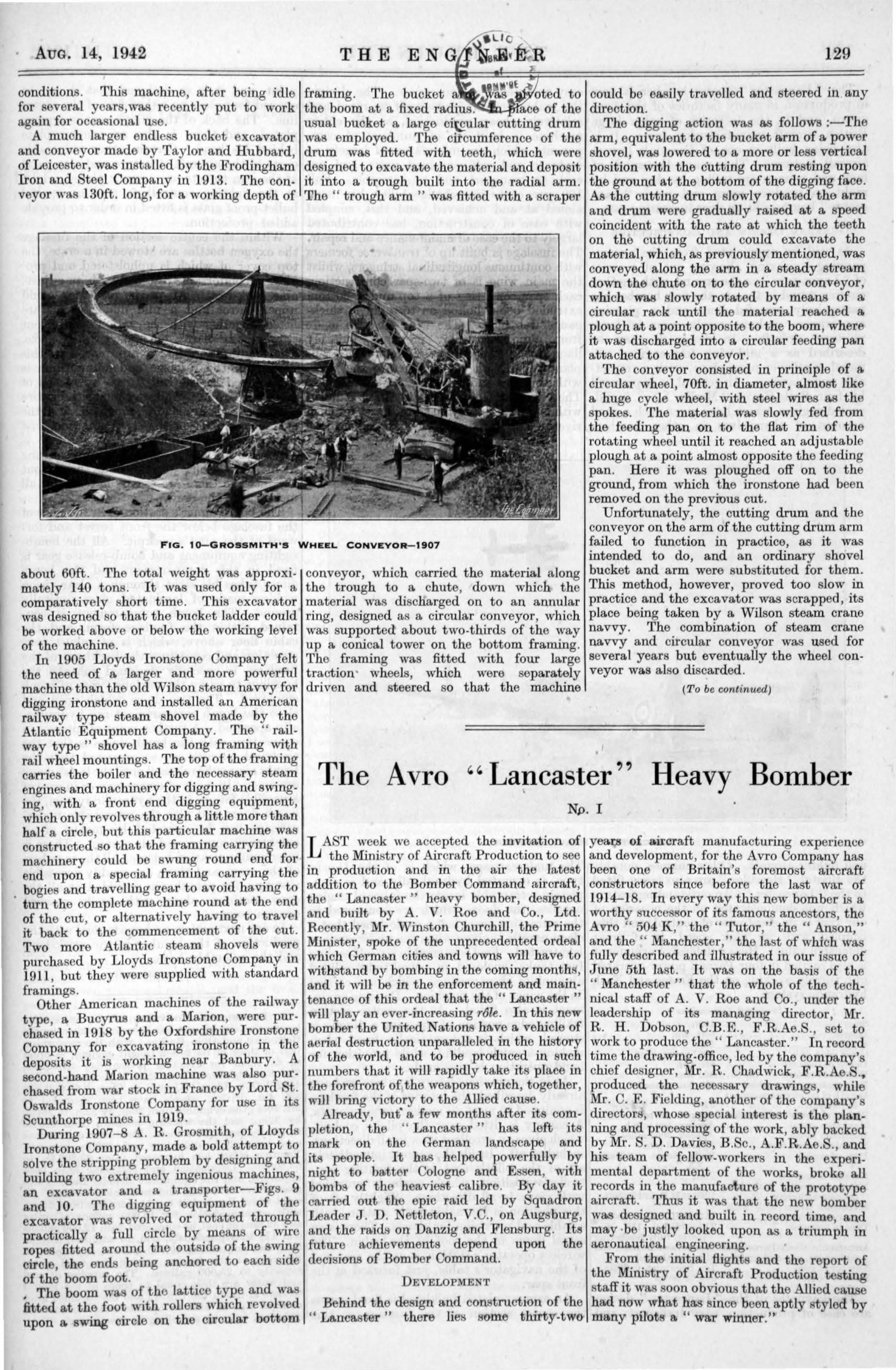
The digging action was a.s follows :-The arm, equivalent to the bucket arm of a power shovel, was lowered to a more or loss vertical position with the cutting drum resting upon the ground at the bottom of the d igging face. As the cutting drum slowly rotated the arm and drum were gradually raised a.t a speed coincident with the rate at which the teeth on the cutting drum could excavate the material, which, as previously mentioned, was conveyed along the arm in a steady stream down the chute on to the circular conveyor, which was slowly rotated by means of a circular rack until the material reached a. plough at a point opposite to the boom, where it was discharged into a circular feeding pan attached to the conveyor.
The conveyor consisted in principle of a. circular wheel, 70ft. in diameter, almost like a huge cycle wheel, with steel wires as the spokes. The material was slowly fed from the feeding pan on to the flat rim of the rotating wheel until it reached an adjustable plough at a point almost opposite the feeding pan. Here it was ploughed off on to the ground, from which the ironstone had been removed on the prevrous cut.
FIG. 10-GROS SMITH 'S WHEEL CONVE YOR- 1907
Unfortunately, the cutting drum and the conveyor on the arm of the cutting drum arm failed to function in practice, as it was intended to do, and an ordinary shovel bucket and arm were substituted for them. This method, however, proved too slow in practice and the excavator was scrapped, its place being taken by a Wilson steam crane navvy. The combination of steam crane navvy and circular conveyor was used for several years but eventually the wheel conveyor was also discarded.
about 60ft. The total weight was approximately 140 tons. It was used only for a comparatively short time. This excavator was designed so that the bucket ladder could be worked above or below the working level of the machine.
In 1905 Lloyds Ironstone Company felt the need of a larger and more powerful machine than the old Wilson steam navvy for digging ironstone and installed an American railway type steam shovel made by the Atlantic Equipment Company. The " railway type" shovel ha.s a long framing with rail wheel mountings. The top of the framing carries the boiler and the necessary steam engines and machinery for digging and swinging, with a front end digging equipment, which only revolveR through a. little more than half a circle, but this particular machine was constructed so that the framing carrying the machinery could be swung round end for end upon a special framing carrying the
. bogie and travelling gear to avoid having to turn the complete machine round at the end of the cut, or alternatively having to travel it back to the commencement of the cut. Two more Atlantic steam shovels were purchased by Lloyds Ironstone Company in 1911, but they wore supplied with standard framings.
Other American machines of the railway type, a Bucyrus and a Marion, were purchased in 1918 by the Oxford hire Ironstone Company for excavating ironstone ip. the deposits it is working near Banbury. A second-hand Marion machine was also pru·cha.sed from war stock in France by Lord • t. Oswalds IronRtone Company for use in its Scunthorpe mines in 1919.
During 1907- 8 A. R . Grosmith, of Lloyds Ironstone Company, made a bold attempt to solve the stripping problem by designing and building two extremely ingenious machines, an excavator and a transporter-Figs. 9 and 10. The digging equipment of the excavator was revolved or rotated through practically a full circle by means of wire ropes fitted around the outsido of the s~g circle, the ends being anchored to each s1dc of the boom foot . , The boom was of the lattice t ype and was fitted at the foot with rollers which revolved upon a. swing circle on the circular bottom
conveyor, which carried t he material along the trough to a chute, down which the material was discharged on to an annular ring, designed as a circular conveyor, which was supported about two-thirds of the way up a conical tower on the bottom framing. The framing was fitted with four large traction wheels, which were separately driven and steered so that the machine
•
(To be continued)
The Avro '' Lancaster'' Heavy Bomber •
Np. I •
LAST week we accepted the invitation of the Ministry of Aircraft Production to see
in production and in the air the latest addition to the Bomber Command aircraft, the " Lancaster " heavy bomber, designed and built by A. V. Roe and Co., Ltd. Recently, Mr. vVinston Churchill, the Prime Minister, spoke of the unprecedented ordeal which German cities and towns will have to withstand by bombing in the coming month~, and it will be in the enforcement and maintenance of this ordeal that the " Lancaster " will play an ever-increasing role. In this new bomber the United Nation have a. vehicle of aerial destruction unparalleled in the history of the world, and to be produced in such numbers that it will rapidly t ake its plaee in the forefront of the weapons which, together, will bring victory to the Allied cause.
Already, buf a few months after its completion, the " Lancaster " has left its mark on the German landscape and its people. It has helped powerfully by night to batter Cologne and E sen, with bombs of the heaviest calibre. By day it carried out tho epic raid led by Squadron Leader J . D . Nettleton, V.C., on Augsburg, and the raidH on Danzig and Flensburg. Its future achievements depend upon the decisions of Bomber Command.
D EVELOPMENT
Behind the design and construction of the " La.ncaster " there lies some thirty-two
yea.QJ of aircraft manufacturing experience and development, for the A vro Company has been one of Britain's foremost aircraft constructors since before the last war of 1914-18. In every way this new bomber is a worthy successor of its famous ancestors, the A vro cc 504 K ," the " Tutor," the cc Anson," and the " Manchester," the last of which was fully described and illustrated in our issue of June 5th last . It wa on the basis of the " Manchester " that the whole of the t echnical staff of A. V. Roe and Co., under the leadership of its managing director, Mr. R . H . Dobson, C.B.E ., F .R .Ae.S., set to work to produce the " Lancaster. " In record ti~e tho ~rawing-office, lod by the company's ch1ef des1gner, Mr. R . Chadwick, F .R .Ae.S . ., produced the necessary drawings, while ~·C. E . Fielding, another of the company' drrectors, whose special intore t i the planning and processing of the work, ably backed b{" Mr. S. D. Davies, B .Sc., A.F.R.Ae.S., and his team of fellow-workers in t he experimental ~epartment of the works, broke all records m the manufacture of the prototype aircraft. Thus it wa. that the new bomber w&S designed and built in record timo and may ·be justly looked upon as a triumph in aeronautical engineering. Fro~ .the initial. flights and the report of
the Miru try of A1rcraft Production testing staff it was soon obvious that the Allied cause had now what has since been aptly styled by many pilots a '' war winner.' '
I
•
. 130
The " Lancaster" heavy bomber is now in production in many factories of the A vro group, and in the factories of other large British aircraft manufacturin,g firms. It is also being built in one of Canada's largest aircraft factories. Thus many thousands of men and women are toiling by day and by night to produce more and more " Lancaster" bombers at an ever-increasing rate.
GENERA!, DESIGN AND CONSTRUCTION
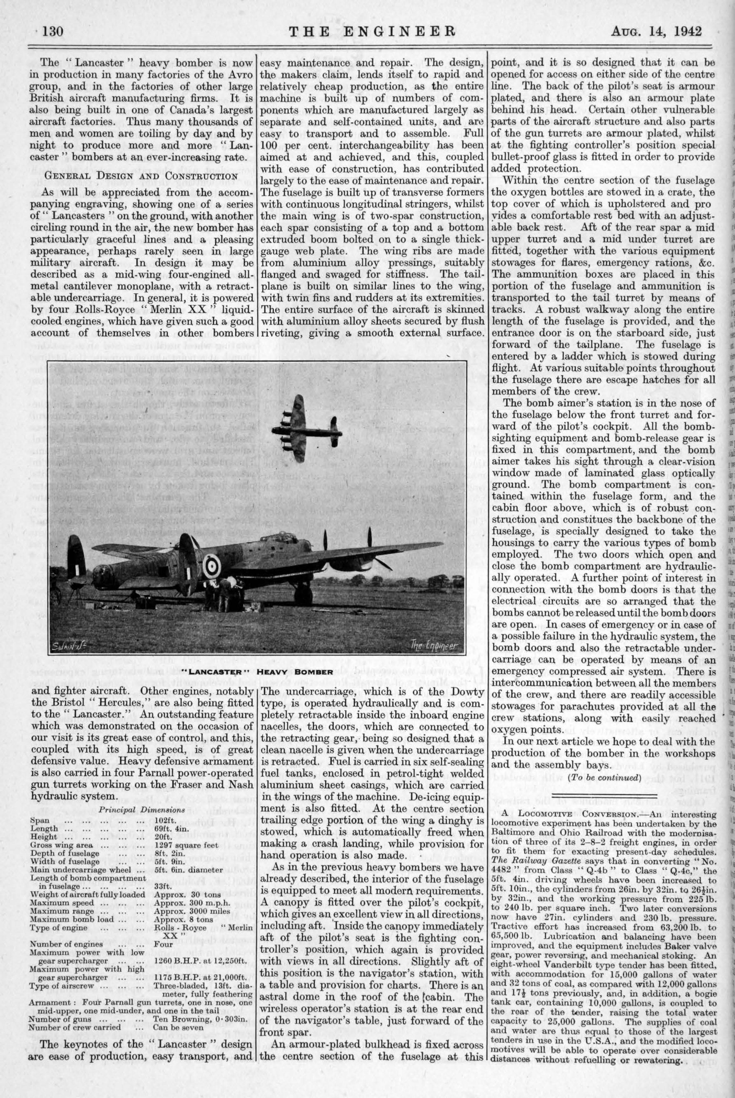
As will be appreciated from the accompanying engraving, showing one of a series of " Lancasters " on the ground, with another circling round in the air, the new bomber has particularly graceful lines and a. pleasing appearance, perhaps rarely seen in large military aircraft. In design it may be described as a mid-wing four-engined allmetal cantilever monoplane, with a retractable undercarriage. In general, it is powered by four Rolls-Royce " Merlin XX " liquidcooled engines, which have given such a good account of themselves in other bombers
•
•
•
•
•
THE ENGINEER
easy maintenance and repair. The design, the makers claim, lends itself to rapid and relatively cheap production, as the entire machine is built up of numbers of components which are manufactured largely as separate and self-contained units, and a.r'~ easy to transport and to assemble. Full lOO per cent. interchangeability has been aimed at and achieved, and this, coupled with ease of construction, has contributed largely to the ease of maintenance and repair. The fuselage is built up of transverse formers with continuous longitudinal stringers, whilst the main wing is of two-spar construction, each spar consisting of a top and a bottom extruded boom bolted on to a single thickgauge web plate. The wing ribs are made from aluminium alloy pressings, suitably fla.nged and swaged for stiffness. The tailplane is built on similar lines to the wing, with twin fins and rudders at its extremities. The entire surface of the aircraft is skinned with alumjnium alloy sheets secured by flush riveting, giving a. smooth external surface.
• •
• •
• • LANCASTER " HEAVY BOMBER
and fighter aircraft. Other engines, notably the Bristol " Hercules," are also being fitted to the " Lancaster ." An outstanding feature which was demonstrated on the occasion of our visit is its great ease of control, and this, coupled with its high speed, is of great defensive value. Heavy defensive armament is also carried in four Pa.rnall power-operated gun turrets working on the Fraser and Nash hydraulic syst em .
Principal DimenBionB ::)pan .. . .. . .. . .. . .. . 102ft. Length .. . .. . .. . .. . 69ft. 4in. Height .. . .. . .. . .. . .. . 20ft. Gross wing area. .. . 1297 square feet Depth of fuselage .. . .. . 8ft. 2in. Width of fuselage . . . 5ft. 9in. Main undercarriage wheel . . . 5ft. 6in. diameter Length of bomb compartment
in fuselage .. . .. . .. . .. . Weight of aircraft fully loaded Maximum speed . . . . . . . .. Maximum range . . . . . . . .. Maximum bomb load . . . . . . Type of engine .. . .. . .. .
Number of engines ... ... Maximum power with low
gear supercharger . . . . ..
33ft. Approx. 30 tons Approx. 300 m.p.h. Approx. 3000 miles Approx. 8 tons Rolls - Royce " Merlin
XX" Four
1260 B.H.P. at 12,250ft. Maximum power with high
gear supercharger . . . . .. Type of ai rscrew . . . . . . . ..
1175 B.H.P. at 21,000ft. Three-bladed, 13ft. dia
meter, fully feathering Armament: Four Parnall gun turrets, one in nose, one
mid-upper, one mid-under, and one in the tail Number of guns . .. ... ... Ten Browning, 0· 303in. Number of crew carried ... Can be seven
The keynotes of the " Lancaster" design are ease of production, easy transport, and
The undercarriage, which is of the Dowty type, is operated hydraulically and is completely retractable inside the inboard engine nacelles, the doors, which are connected to the retracting gear, · being so designed that a clean nacelle is given when the undercarriage is retracted. Fuel is carried in six self-sealing fuel tanks, enclosed in petrol-tight welded aluminium sheet casings, which are carried in the wings of the machine. De-icing equipment is also fitted. At the centre section trailing edge portion of the wing a dinghy is stowed, which is automatically freed when making a crash landing, while provision for hand operation is also made. ·
As in the previous heavy bombers we have already described, the interior of the fuselage is equipped to meet all modern requirements. A canopy is fitted over the pilot 's cockpit, which gives an excellent view in all directions,
' including aft. Inside the Ca!J.opy immediately aft of the pilot's seat is the fighting controller's position, which again is provided with views in all directions. Slightly aft of this position is the navigator's station, with a table and provision for charts. There is a.n astral dome in the roof of the [cabin. The wireless operator's station is at the rear end of the navigator's table, just forward of the front spar.
An armour-plated bulkhead is fixed across the centre section of the fuselage at this
AuG. 14, 1942
point, and it is so designed that it can be opened for access on either side of the centre line. The back of the pilot's seat is armour plated, and there is also an armour plate behind his head. Certain other vulnerable parts of the aircraft structure and also parts of the gun turrets are armour plated, whilst at the fighting controller's pqsition special bullet-proof glass is fitted in order to provide added protection.
Within the centre section of the fuselage the oxygen bottles are stowed in a crate, the top cover of which is upholstered and pro yides a. comfortable rest bed with an adjustable back rest . Mt of the rear spar a. mid upper turret and a. mid under turret are fitted, together with the various equipment stowages for flares, emergency rations, &c. The ammunition boxes are placed in this portion of the fuselage and ammunition is transported to the tail turret by means of tracks. A robust walkway along the entire length of the fuselage is provided, and the entrance door is on the starboard side, just forward of the tailplane. The fuselage is entered by a ladder which is stowed during flight . At various suitable points throughout the fuselage there are escape hatches for all members of the crew .
The bomb a.imer's station is in the nose of the fuselage below the front turret and forward of the pilot's cockpit. All the bombsighting equipment and bomb-release gear is fixed in this compartment, and the bomb aimer takes his sight through a clear-vision window made of laminated glass optically ground. The bomb compartment is contained within the fuselage form, and the cabin floor above, which is of robust con--struction and constitues the backbone of the fuselage, is specially designed to take the housings to carry the various types of bomb employed. The two doors which open and close the bomb compartment are hydraulically operated. A further point of interest in connection with the bomb doors is that the electrical circuits are so arranged that the bombs cannot be released until the bomb doors are open. In cases of emergency or in case of a possible failure in the hydraulic system, the bomb doors and also the retractable undercarriage can be operated by means of an emergency compressed air system. There is intercommunication between all the members of the crew, and t here are readily ~ccessible stowages for parachutes provided at all the crew stations, along with easily reached · oxygen points.
In our next article we hope to deal with the production of the bomber in the workshops and the assembly bays.
(To be continued)
A L OCOMOTivE CoNvERSION.-Au intoresting locomotive experiment has been undertaken by the Baltimore and Ohio Railroad with the modernisation of three of its 2-8-2 freight engines, in order to fit them for exacting present-day schedules. The Railway Gazette says that in converting "No. 4482 " from Class " Q-4b " to Class " Q-4c," the 5ft. 4in. driving wheels have been increased to 5ft. lOin ., the cylinders from 26in. by 32in. to 26lin. by 32in., and the working pressure from 225lb. to 240 lb. per square inch. Two later conversions now have 27in. cylinders and 230 lb. pressure. Tractive effort has increased from 6:l,200 lb. to ?!5,500 lb. Lubrication and balancing have been unproved, and the equipment includes Baker valve gear, p ower reversing, and mechanical stoking. An ei~ht-wheel V anderbilt type tender has been fitted, Wlth accommodation for 15,000 gallons of water and :l2 tons of coal, as compared with 12,000 gallons and 17! tons previously, and, in addition, a bogie tank car, containing 10,000 gallons, is coupled to the roar of tha tender, raising the total water capacity to 25,000 gallons. The supplies of coal and water are thus equal to those of the largest tenders in use in the U.S.A., and the modified loco~otives will be able to operate over considerable distances. without refllelling or rewatering. . ,
•
.. l i
t
•
,. ·-
.m
• ..
' •
•
! I I
!
i
•
I