Embed Size (px)
Citation preview
Jean-Paul Linnartz, 2007 (CDMA)
The Basics of Code Division Multiple Access
Jean-Paul M.G. LinnartzPhilips Research and TU/e

Jean-Paul Linnartz, 2007 (CDMA)
Outline
Multiple access methods – FDMA, TDMA, CDMA
Spread spectrum methods– Frequency Hopping – Direct Sequence
• More on code sequences• IS-95 cellular CDMA• Rake receiver
– Multi-Carrier CDMA– UltraWideBand pulse radio
Jean-Paul Linnartz, 2007 (CDMA)
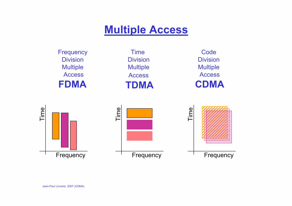
Multiple Access
Frequency Division Multiple Access
FDMA
Code Division Multiple Access
CDMA
Time Division Multiple Access
TDMA
Frequency
Tim
e
Frequency
Tim
e
Frequency
Tim
e
Jean-Paul Linnartz, 2007 (CDMA)
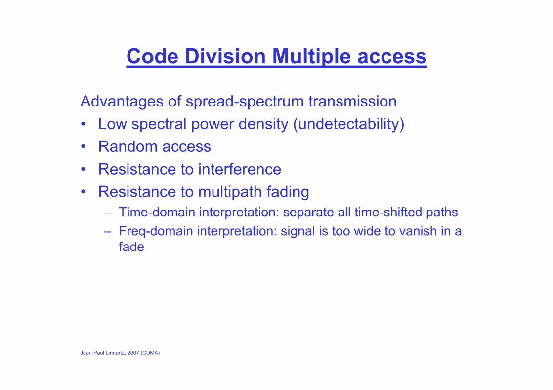
Code Division Multiple access
Advantages of spread-spectrum transmission• Low spectral power density (undetectability)• Random access• Resistance to interference• Resistance to multipath fading
– Time-domain interpretation: separate all time-shifted paths– Freq-domain interpretation: signal is too wide to vanish in a
fade
Jean-Paul Linnartz, 2007 (CDMA)
Spreading methods
Frequency Hopping– Applied in GSM, Military, ISM bands, Blue tooth
Direct sequence– Applied in IS-95 IS-136 Cellular CDMA, GPS, UMTS, W-
CDMA, Military
Multi-Carrier CDMA– In research
Ultra Wide Band– Speculations only (in 1999)
Jean-Paul Linnartz, 2007 (CDMA)
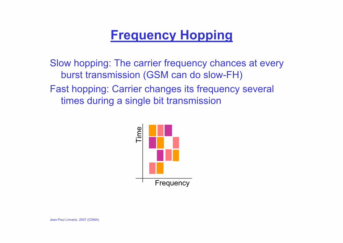
Frequency Hopping
Slow hopping: The carrier frequency chances at every burst transmission (GSM can do slow-FH)
Fast hopping: Carrier changes its frequency several times during a single bit transmission
Frequency
Tim
e

Jean-Paul Linnartz, 2007 (CDMA)
Direct Sequence
User data stream is multiplied by a fast code sequence
Example: – User bits 101 (+ - +)– Code 1110100 (+ + + - + - -); spead factor = 7
EXORUser Bits
Code Sequence
1 -1 -1-111 1 -1 1 11-1-1 -1 1 -1 -1-111 1
User bit-1 = 1 User bit0 = -1 User bit+1 = 1

Jean-Paul Linnartz, 2007 (CDMA)
Multi-Carrier
Direct Sequence + OFDMDirect sequence where
spreading sequence is FFT of normal code sequence
Frequency
Tim
e
+ - + -
+ - +-
+ - +-
Code sequence: (hor) + - + -Bit sequence: (vert) + - -
Spread CodeU
ser Data
cos(ωct+ ωst)
cos(ωct)
cos(ωct+ iωst)
cos(ωct+ (N-1)ωst)
+1
-1
-1
+1
Jean-Paul Linnartz, 2007 (CDMA)
Ultra Wide Band
Transmission of very short pulses (fraction of a nanosecond), with bandwidth of many Gigahertz.
Receiver “correlates” to find pulses
Practical problems:– Synchronisation– The signal will experience dispersion, and many individual
reflections are received. It is extremely difficult to gather the energy from many paths
– While TX is power-efficient, the RX typically consumes a lot of power.
Jean-Paul Linnartz, 2007 (CDMA)
Direct Sequence CDMA
Jean-Paul Linnartz, 2007 (CDMA)
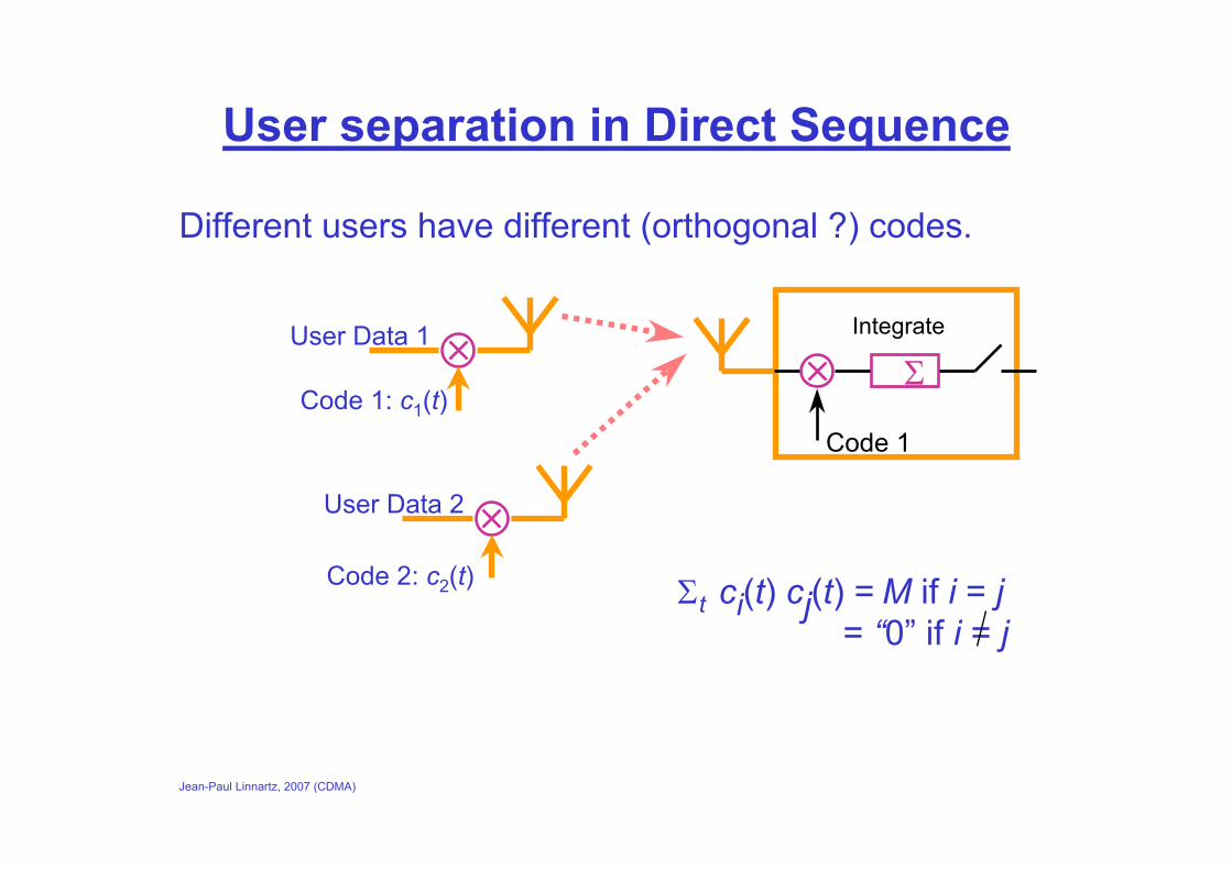
User separation in Direct Sequence
Different users have different (orthogonal ?) codes.
Integrate
Σ
Code 1Code 1: c1(t)
User Data 1
User Data 2
Code 2: c2(t) Σt ci(t) cj(t) = M if i = j= “0” if i = j

Jean-Paul Linnartz, 2007 (CDMA)
Multipath Separation in DS
Different delayed signals are orthogonal
Integrate
Σ
Code 1Code 1: c1(t)
User Data 1
Σt ci(t) ci(t) = M Σt ci(t) ci(t+T) = “0” if T ≠ 0
Delay T
Jean-Paul Linnartz, 2007 (CDMA)
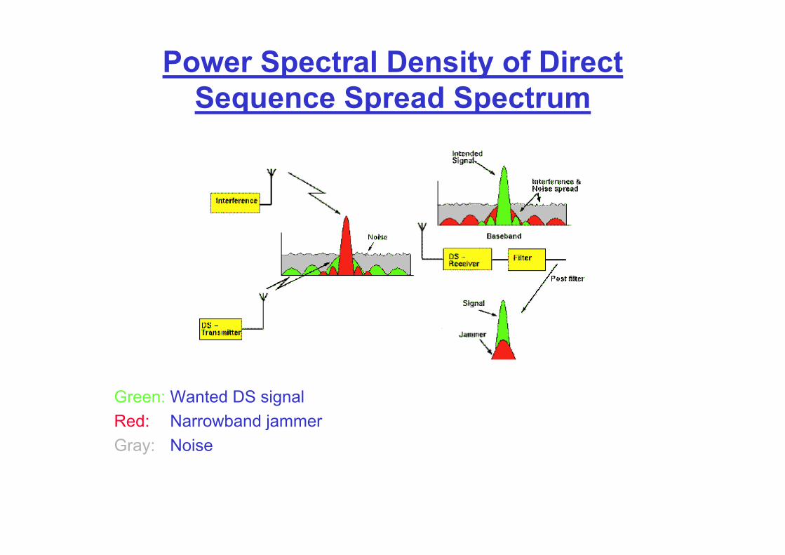
Power Spectral Density of Direct Sequence Spread Spectrum
Green: Wanted DS signalRed: Narrowband jammerGray: Noise

Jean-Paul Linnartz, 2007 (CDMA)
Effects of Multipath (I)
Frequency
Tim
e
Frequency
Tim
e
Frequency
Tim
e
Wideband Narrowband OFDM
Jean-Paul Linnartz, 2007 (CDMA)
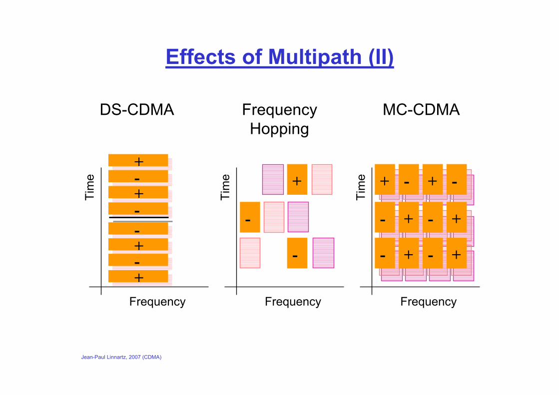
Effects of Multipath (II)
Frequency
Tim
e +
-
-
Frequency
Tim
e
Frequency
Tim
e + - + -
+ - +-
+ - +-
+-+--+-+
DS-CDMA FrequencyHopping
MC-CDMA
Jean-Paul Linnartz, 2007 (CDMA)
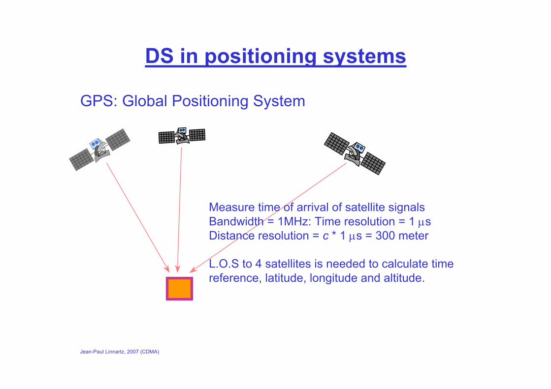
DS in positioning systems
GPS: Global Positioning System
Measure time of arrival of satellite signalsBandwidth = 1MHz: Time resolution = 1 µsDistance resolution = c * 1 µs = 300 meter
L.O.S to 4 satellites is needed to calculate time reference, latitude, longitude and altitude.
Jean-Paul Linnartz, 2007 (CDMA)
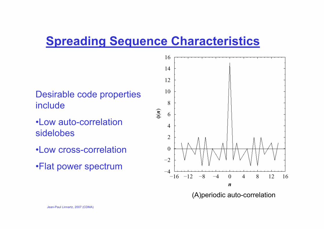
Spreading Sequence Characteristics
Desirable code properties include
•Low auto-correlation sidelobes
•Low cross-correlation
•Flat power spectrum
(A)periodic auto-correlation
Jean-Paul Linnartz, 2007 (CDMA)
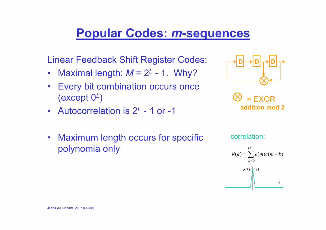
Popular Codes: m-sequences
Linear Feedback Shift Register Codes:• Maximal length: M = 2L - 1. Why?• Every bit combination occurs once
(except 0L)• Autocorrelation is 2L - 1 or -1
• Maximum length occurs for specific polynomia only
∑−
=
−=1
0)()()(
M
mkmcmckR
correlation:
R(k) M
k
D DD
= EXORaddition mod 2
Jean-Paul Linnartz, 2007 (CDMA)
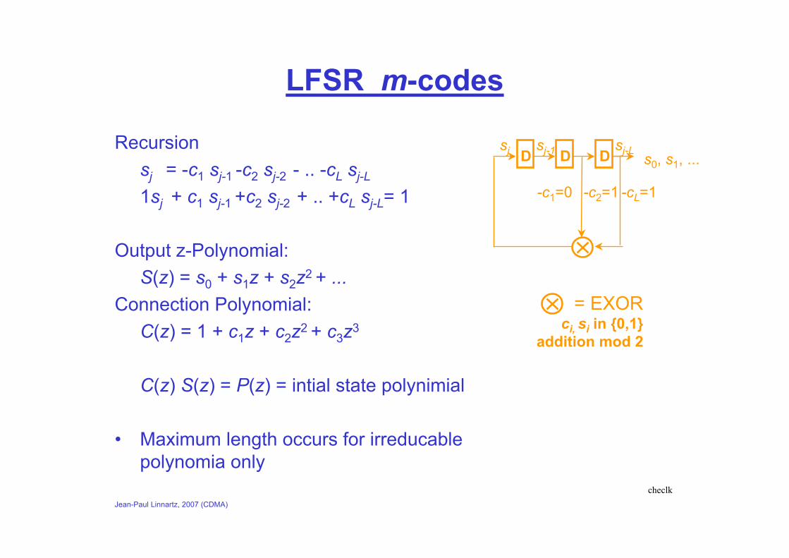
LFSR m-codes
Recursionsj = -c1 sj-1 -c2 sj-2 - .. -cL sj-L
1sj + c1 sj-1 +c2 sj-2 + .. +cL sj-L= 1
Output z-Polynomial:S(z) = s0 + s1z + s2z2 + ...
Connection Polynomial:C(z) = 1 + c1z + c2z2 + c3z3
C(z) S(z) = P(z) = intial state polynimial
• Maximum length occurs for irreducablepolynomia only
D DD
= EXORci, si in {0,1}
addition mod 2
-c2=1 -cL=1-c1=0
s0, s1, ...sj sj-1 sj-L
checlk
Jean-Paul Linnartz, 2007 (CDMA)
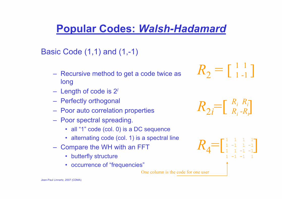
Popular Codes: Walsh-Hadamard
Basic Code (1,1) and (1,-1)
– Recursive method to get a code twice as long
– Length of code is 2l
– Perfectly orthogonal– Poor auto correlation properties– Poor spectral spreading.
• all “1” code (col. 0) is a DC sequence• alternating code (col. 1) is a spectral line
– Compare the WH with an FFT• butterfly structure• occurrence of “frequencies”
1 11 -1R2 = [ ]
R2i=[ ]
R4=[ ]
Ri RiRi -Ri
1 1 1 11 -1 1 -11 1 -1 -11 -1 -1 1
One column is the code for one user
Jean-Paul Linnartz, 2007 (CDMA)
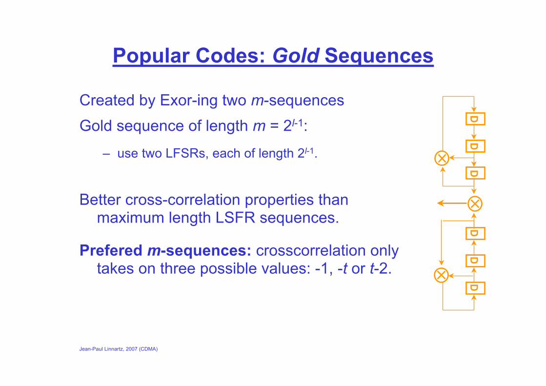
Popular Codes: Gold Sequences
Created by Exor-ing two m-sequencesGold sequence of length m = 2l-1:
– use two LFSRs, each of length 2l-1.
Better cross-correlation properties than maximum length LSFR sequences.
Prefered m-sequences: crosscorrelation only takes on three possible values: -1, -t or t-2.
DD
DD
DD
Jean-Paul Linnartz, 2007 (CDMA)
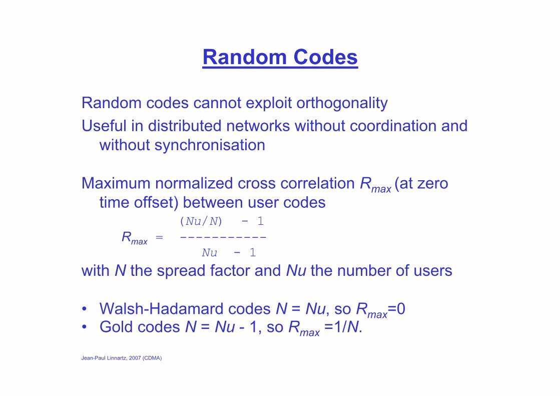
Random Codes
Random codes cannot exploit orthogonalityUseful in distributed networks without coordination and
without synchronisation
Maximum normalized cross correlation Rmax (at zero time offset) between user codes
(Nu/N) - 1Rmax = -----------
Nu - 1with N the spread factor and Nu the number of users
• Walsh-Hadamard codes N = Nu, so Rmax=0• Gold codes N = Nu - 1, so Rmax =1/N.
Jean-Paul Linnartz, 2007 (CDMA)
Cellular CDMA
IS-95: proposed by QualcommW-CDMA: future UMTS standard
Advantages of CDMA• Soft handoff• Soft capacity• Multipath tolerance: lower fade margins needed• No need for frequency planning
Jean-Paul Linnartz, 2007 (CDMA)
Cellular CDMA
Problems• Self Interference
– Dispersion causes shifted versions of the codes signal to interfere
• Near-far effect and power control– CDMA performance is optimized if all signals are received
with the same power – Frequent update needed – Performance is sensitive to imperfections of only a dB– Convergence problems may occur
Jean-Paul Linnartz, 2007 (CDMA)
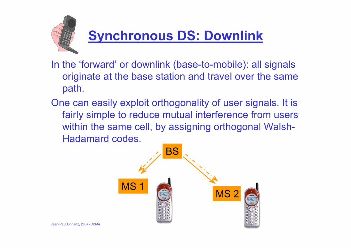
Synchronous DS: Downlink
In the ‘forward’ or downlink (base-to-mobile): all signals originate at the base station and travel over the same path.
One can easily exploit orthogonality of user signals. It is fairly simple to reduce mutual interference from users within the same cell, by assigning orthogonal Walsh-Hadamard codes.
BS
MS 2MS 1

Jean-Paul Linnartz, 2007 (CDMA)
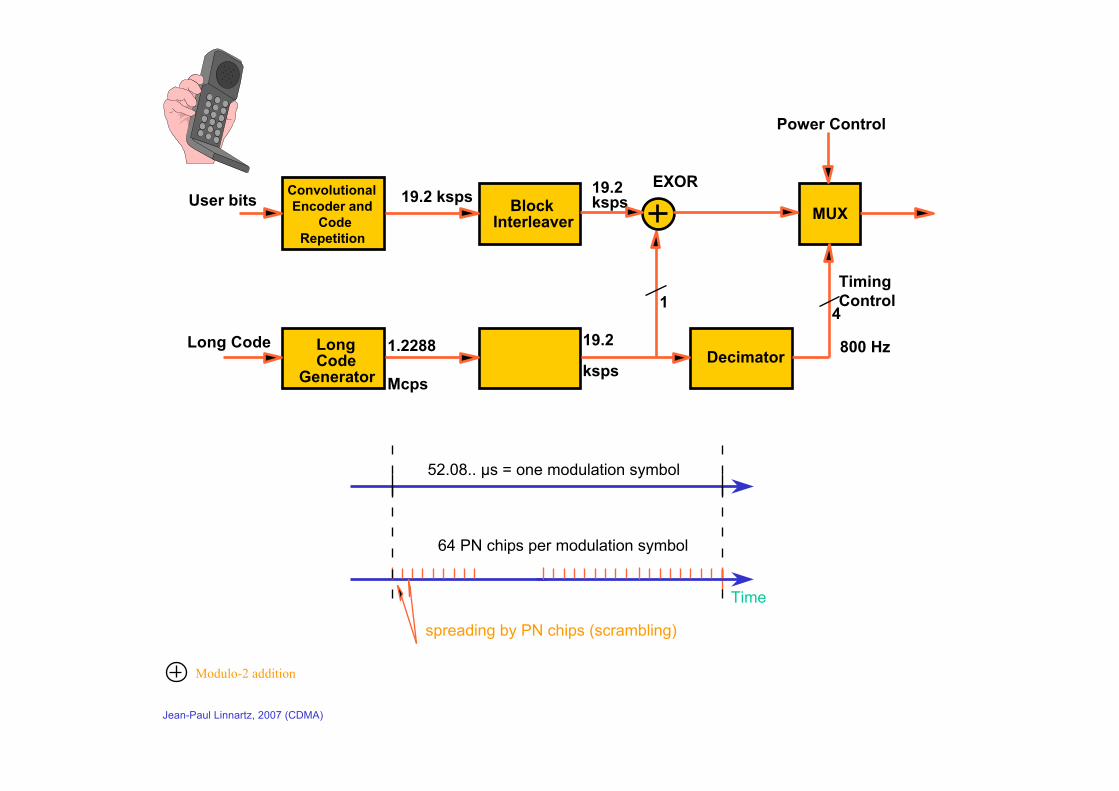
IS-95 Forward link (‘Down’)
• Logical channels for pilot, paging, sync and traffic. • Chip rate 1.2288 Mchip/s = 128 times 9600 bit/sec • Codes:
– Length 64 Walsh-Hadamard (for orthogonality users)– maximum length code sequence (for effective spreading and
multipath resistance
• Transmit bandwidth 1.25 MHz • Convolutional coding with rate 1/2
Jean-Paul Linnartz, 2007 (CDMA)
User bits ConvolutionalEncoder and
Code Repetition
Block Interleaver
19.2 ksps
1.2288
Mcps
Long Code
Generator
Long Code
EXOR
19.2
ksps
19.2 ksps
1
Power Control
4
800 Hz
Timing Control
MUX
52.08.. µs = one modulation symbol
64 PN chips per modulation symbol
spreading by PN chips (scrambling)
Decimator
Modulo-2 addition
Time

Jean-Paul Linnartz, 2007 (CDMA)
IS-95 BS Transmitter
PNIPNQ
Com
bining, weighting and
quadraturem
odulationPilot: DC-signal
W0
W0
WjUserdata
Long code
Blockinterleaver
Convol.Encoder
Sync data
EXOR (addition mod 2)
Jean-Paul Linnartz, 2007 (CDMA)
Rationale for use of codes
Long code: scrambling to avoid that two users in neighboring cells use the same code
short code: user separation inone cellPN exor WH:
– maintains excellent crosscorrelation– improves autocorrelation (multipath)
Jean-Paul Linnartz, 2007 (CDMA)
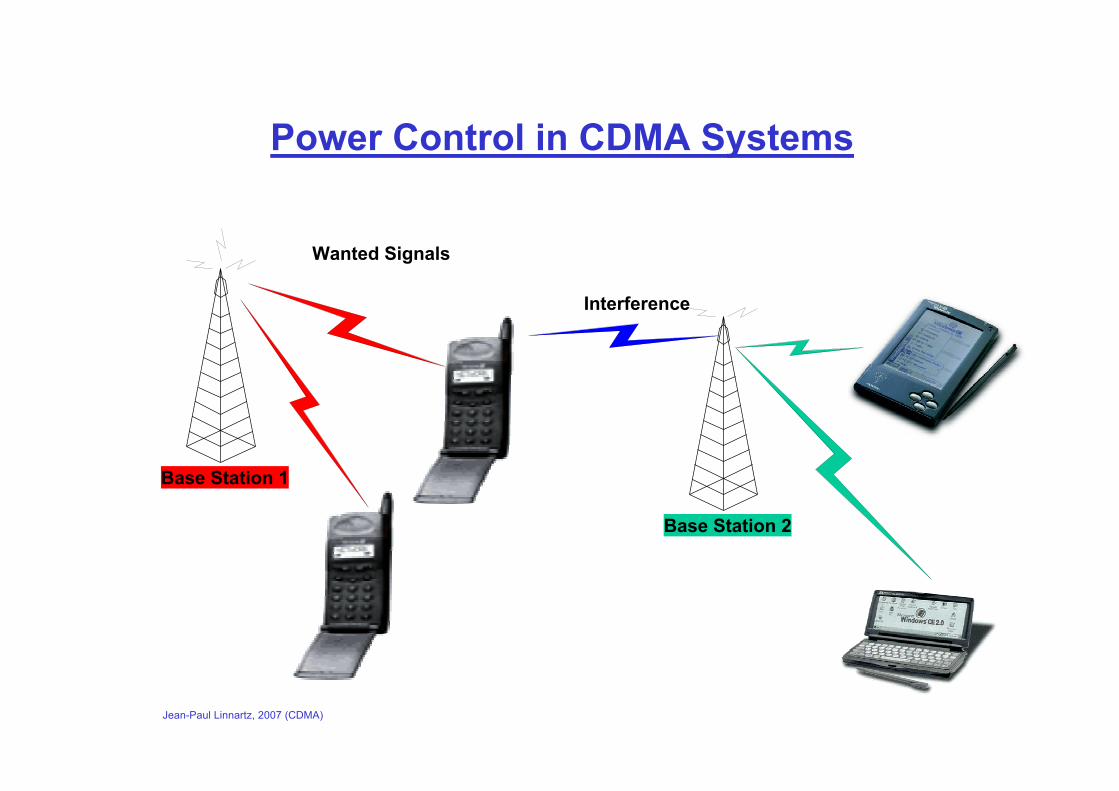
Base Station 1
Interference
Wanted Signals
Power Control in CDMA Systems
Base Station 2

Jean-Paul Linnartz, 2007 (CDMA)
Power ControlAim of power control - optimise received power by varying transmitted power
Two methods - open loop and closed loop
Open loop - estimate path loss from channel measurements
Closed loop - use feedback from other end of link
What step size– In UMTS steps power steps are about 1 db
What update rate– In UMTS update rate is about 1500Hz
Jean-Paul Linnartz, 2007 (CDMA)
Power Control in IS-95
CDMA performance is optimized if all signals are received with the same power Update needed every 1 msec. (cf. rate of fading) Performance is sensitive to imperfections of only a dB
Jean-Paul Linnartz, 2007 (CDMA)
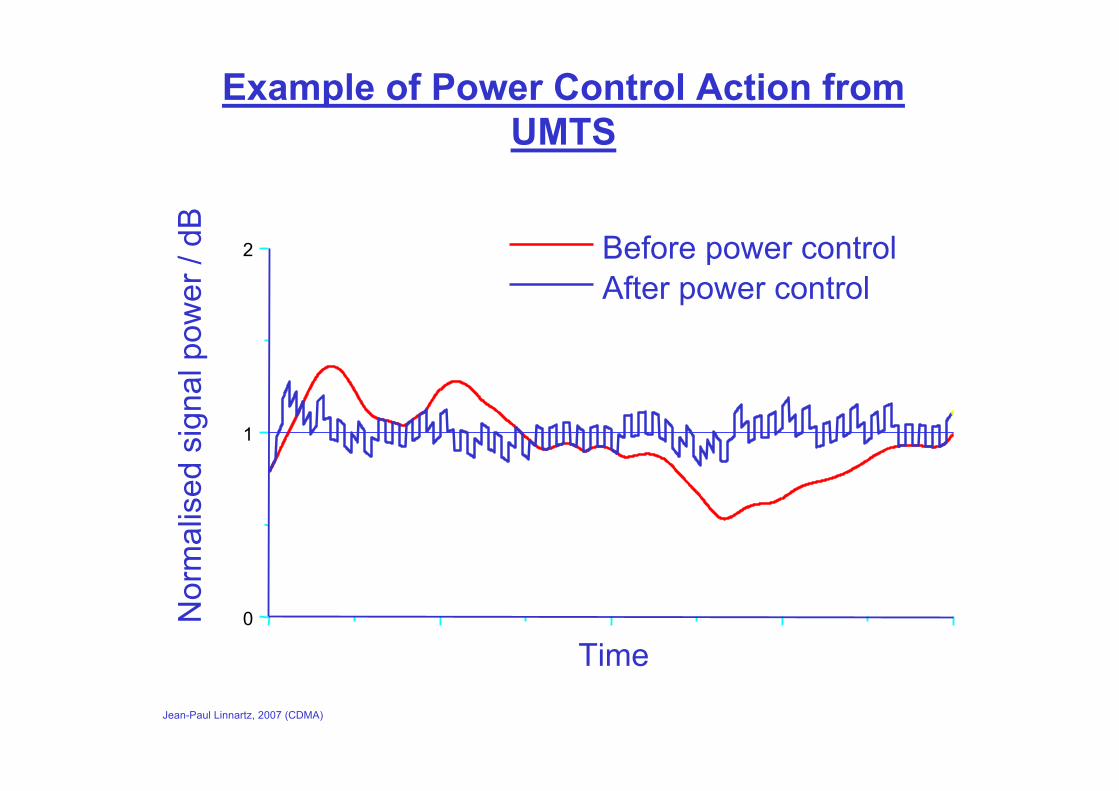
Example of Power Control Action from UMTS
0
1
2
Time
Before power controlAfter power control
Nor
mal
ised
sign
al p
ower
/ dB

Jean-Paul Linnartz, 2007 (CDMA)
Asynchronous DS: uplink
In the ‘reverse’ or uplink (mobile-to-base), it is technically difficult to ensure that all signals arrive with perfect time alignment at the base station.
Different channels for different signalspower control needed
BS
MS 2MS 1
Jean-Paul Linnartz, 2007 (CDMA)
IS-95 Reverse link (‘Up’)
• Every user uses the same set of short sequences for modulation as in the forward link. Length = 215 (modified 15 bit LFSR).
• Each access channel and each traffic channel gets a different long PN sequence. Used to separate the signals from different users.
• Walsh codes are used solely to provide m-aryorthogonal modulation waveform.
• Rate 1/3 convolutional coding.
Jean-Paul Linnartz, 2007 (CDMA)
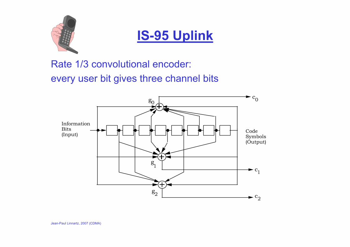
IS-95 Uplink
Rate 1/3 convolutional encoder: every user bit gives three channel bits
c
c
c
Code Symbols (Output)
Information Bits (Input)
g
g
g
0
1
2
1
0
2
Jean-Paul Linnartz, 2007 (CDMA)
Power Control in IS-95
CDMA performance is optimized if all signals are received with the same power Update needed every 1 msec. (cf. rate of fading) Performance is sensitive to imperfections of only a dB
Jean-Paul Linnartz, 2007 (CDMA)
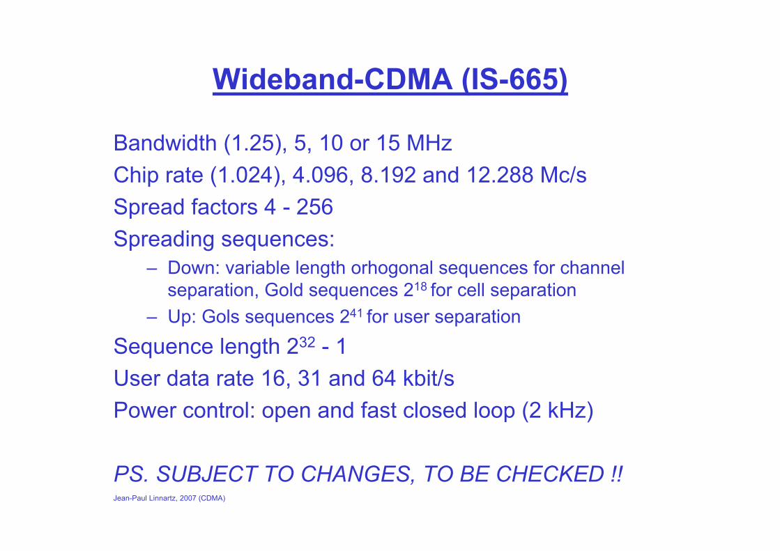
Wideband-CDMA (IS-665)
Bandwidth (1.25), 5, 10 or 15 MHzChip rate (1.024), 4.096, 8.192 and 12.288 Mc/sSpread factors 4 - 256Spreading sequences:
– Down: variable length orhogonal sequences for channel separation, Gold sequences 218 for cell separation
– Up: Gols sequences 241 for user separation
Sequence length 232 - 1User data rate 16, 31 and 64 kbit/sPower control: open and fast closed loop (2 kHz)
PS. SUBJECT TO CHANGES, TO BE CHECKED !!
Jean-Paul Linnartz, 2007 (CDMA)
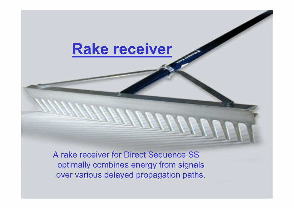
Rake receiver
A rake receiver for Direct Sequence SS optimally combines energy from signals over various delayed propagation paths.
Jean-Paul Linnartz, 2007 (CDMA)
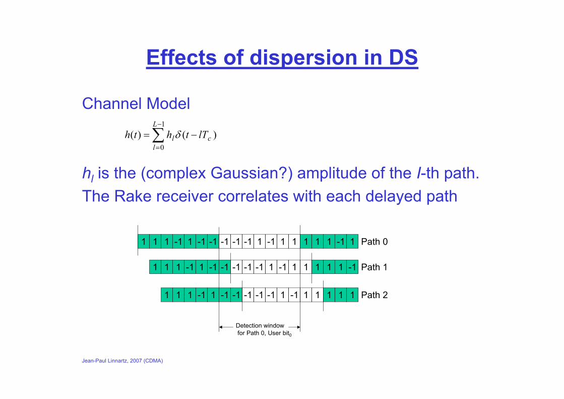
Effects of dispersion in DS
Channel Model
hl is the (complex Gaussian?) amplitude of the I-th path.The Rake receiver correlates with each delayed path
∑−
=
−=1
0)()(
L
lcl lTthth δ
1 -1 -1-111 1 -1 1 11-1-1 -1 1 -111 1
Detection window for Path 0, User bit0
1 -1 -1-111 1 -1 1 11-1-1 -1 1 -111
1 -1 -1-111 1 -1 1 11-1-1 -1 1 11
Path 0
Path 1
Path 2

Jean-Paul Linnartz, 2007 (CDMA)
DS reception: Matched Filter Concept
The optimum receiver for any signal – in Additive white Gaussian Noise– over a Linear Time-Invariant Channel
is ‘a matched filter’:Integrate
Σ
Locally stored reference copy of transmit signal
Channel Noise
Transmit Signal
Jean-Paul Linnartz, 2007 (CDMA)
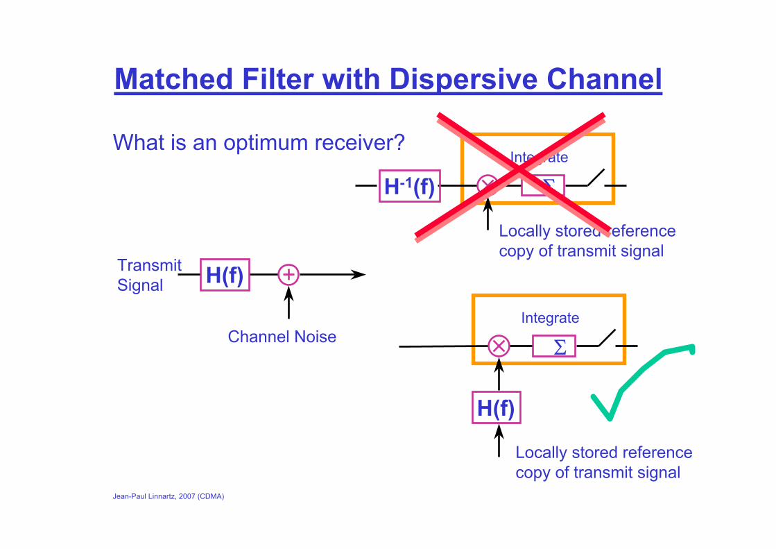
Matched Filter with Dispersive Channel
What is an optimum receiver?
Channel Noise
Transmit Signal H(f)
Integrate
Σ
Locally stored reference copy of transmit signal
H-1(f)
Integrate
Σ
Locally stored reference copy of transmit signal
H(f)
Jean-Paul Linnartz, 2007 (CDMA)
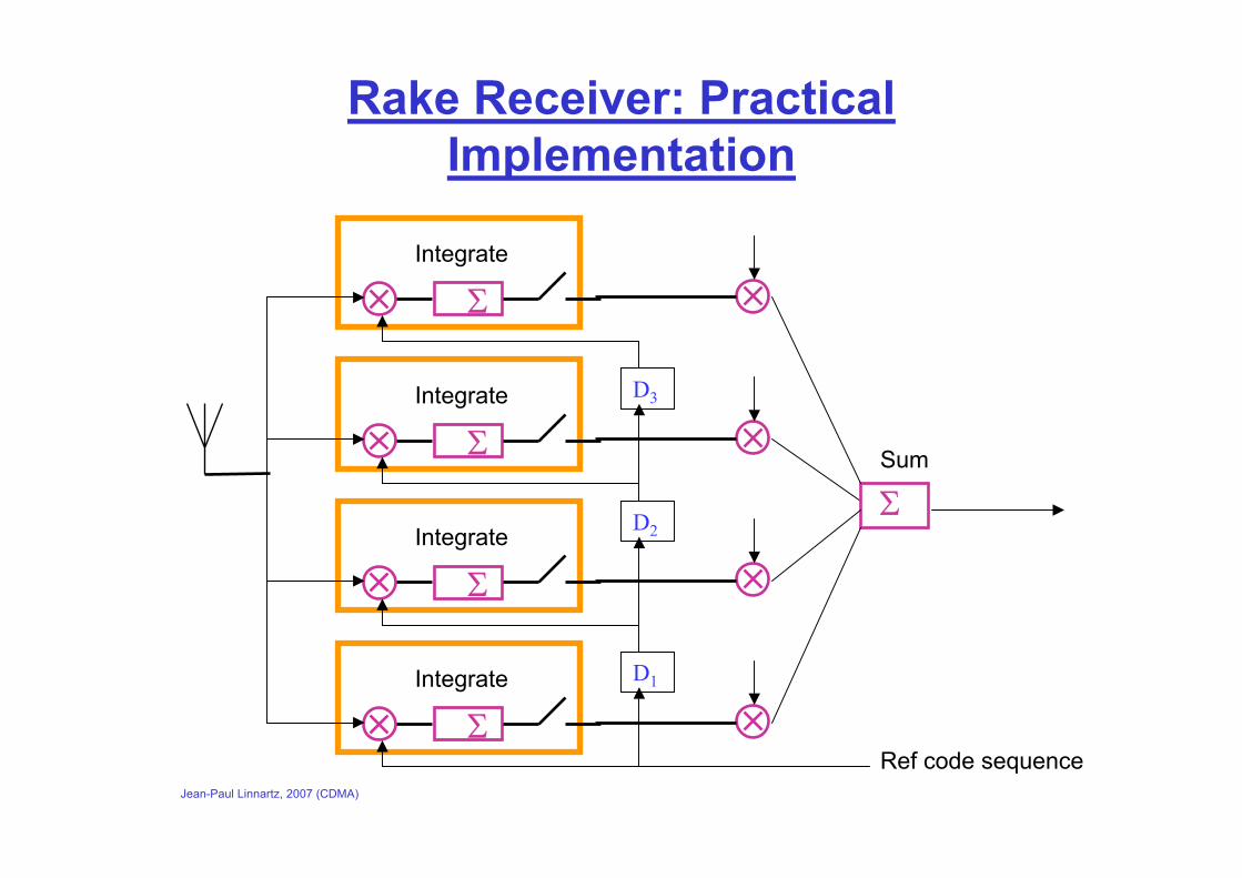
Rake Receiver: Practical Implementation
Integrate
Σ
Ref code sequence
Integrate
Σ
Integrate
Σ
Integrate
Σ
D1
D2
D3
ΣSum
Jean-Paul Linnartz, 2007 (CDMA)
H(f)
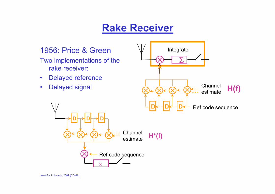
Rake Receiver
1956: Price & GreenTwo implementations of the
rake receiver:• Delayed reference• Delayed signal
Integrate
Σ
H(f)
D DD
Channel estimate
D DD
H*(f)Channel estimate
Ref code sequence
Σ
Ref code sequence
Jean-Paul Linnartz, 2007 (CDMA)
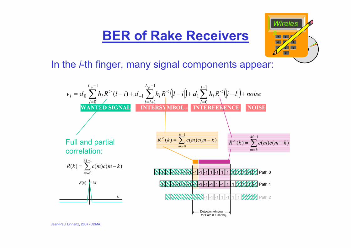
BER of Rake Receivers
In the i-th finger, many signal components appear:
Wireless
( ) ( ) noiseliRhdilRhdilRhdvi
ll
L
ill
L
lli
pp
+−+−+−= ∑∑∑−
=
<−
+=
<−
−
=
>1
01
1
11
1
00 )(
WANTED SIGNAL INTERSYMBOL - INTERFERENCE NOISE
∑−
=
−=1
0)()()(
M
mkmcmckR
Full and partial correlation:
R(k) M
k
∑−
=
< −=1
0)()()(
k
mkmcmckR
1 -1 -1-111 1 -1 1 11-1-1 -1 1 -111 1
Detection window for Path 0, User bit0
1 -1 -1-111 1 -1 1 11-1-1 -1 1 -111
1 -1 -1-111 1 -1 1 11-1-1 -1 1 11
Path 0
Path 1
Path 2
∑−
=
> −=1
)()()(M
kmkmcmckR

Jean-Paul Linnartz, 2007 (CDMA)
BER of Rake
Ignoring ISI, the local-mean BER is
where
with γi the local-mean SNR in branch i.
+−= ∑
= 11
21
0 j
jL
jj
R
BERγ
γπ
πγ
γ γj
j
j iii j
LR=
−∏=≠
1
J. Proakis, “Digital Communications”, McGraw-Hill, Chapter 7.
Wireless
LR = 1
LR = 2LR = 3
BER
Eb/N0
Jean-Paul Linnartz, 2007 (CDMA)
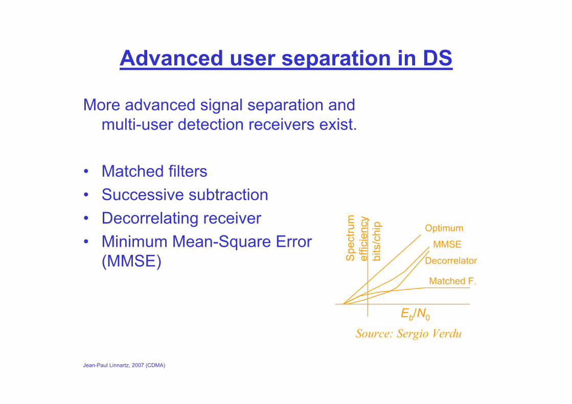
Advanced user separation in DS
More advanced signal separation and multi-user detection receivers exist.
• Matched filters• Successive subtraction• Decorrelating receiver• Minimum Mean-Square Error
(MMSE)
Optimum
MMSE
Decorrelator
Matched F.
Eb/N0
Spe
ctru
m
effic
ienc
ybi
ts/c
hip
Source: Sergio Verdu
Jean-Paul Linnartz, 2007 (CDMA)
Concluding Remarks
DS-CDMA is a mature technology for cellular telephone systems. It has advantages, particularly in the downlink.
The rake receiver ‘resolves’ multipath delays
DS-CDMA has been proposed also for burstymultimedia traffic, but its advantages are less evident