Embed Size (px)
Citation preview

TECHNICAL BULLETIN NO. 332 OCTOBER, 1932
UNITED STAT^ bEJ^AETWESft^OE^^^fcC^ICULTURE
THE BEARING STRENGTH OF WOOD UNDER BOLTS
By GEXMI&B W. TRAYEB
Senior Engineer^ Forest Products Laboratory,^ Branch of Research, Forest Sermoe
CONTENTS
Introduction 1 Limits of the investigation 2 Character of the tests 2
Bearing parallel to the grain 2 Bearing perpendicular to the grain 3 General procedure 3
Proportional limit of a bolted j oint 5 Bolt-bearing strength of wood parallel to the
grain.-- 6 Discussion of test results 6 Safe working stresses parallel to the grain
for common bolts 12 Summarized procedure for calculating safe
loads parallel to the grain 18 Effect of repeated loads -_ 18 Safe working stresses parallel to the grain
for bolts of high strength 20 Bolt-bearing strength of wood perpendicular
to the grain -- 21 Discussion of test results 21
Page Safe working stresses perpendicular to the
grain for common bolts 25 Summarized procedure for calculating safe
loads perpendicular to the grain 29 Safe working stresses perpendicular to the
grain for bolts of high strength.-. 30 Bolt-bearing strength of wood at any angle
with the grain ^ 31 Formula for calculation 31
Details of design 32 One-end loading compared with two-end
loading - 32 C ombined action of several bolts in a j oint 32 Choice of bolt diameter 33 Placement of bolts in a joint 33 Centering and boring the bolt holes 36 Cross bolts 37 Condition of lumber 37
Appendix _ 38 Method of fitting stress curves to the data. 38
INTRODUCTION
The purpose of this bulletin is to supply information essential to the proper design of bolted joints in timber construction. Safe loads for such connections, when computed by the methods given in various textbooks and handbooks now in use, differ widely. Such discrep- ancy is attributed to the fact that no extensive series of actual strength tests of ordinary bolted timber joints, from which safe working values might be selected with assurance, has heretofore been made. This bulletin presents the results of several hundred such tests, in which bolts of various diameters and lengths and timber of l3oth coniferous and hardwood (broad-leaved) species were used. Working values for various types of joint connections, cover- ing a range in direction of bolt pressure from parallel to perpendicu- lar with respect to the grain, are presented. In addition to working stresses, details of design pertaining to such other features as the required spacing of bolts, the proper margin, and so forth are discussed.
1 Maintained by the U. S. Department of Agriculture at Madison, Wis., in cooperation with the University of Wisconsin.
128843°—32—1 1

2 TECH]SriCAL, BULLETIlSr 3 3 2^ U. S. DEPT. OF AGRICULTURE
LIMITS OF THE INVESTIGATION
Substantially all the detailed information in this bulletin applies strictly to common, commercial steel bolts and must not be con- strued as applying to steel aircraft bolts. Several years ago the Forest Products Laboratory made a study of aircraft bolts the results of which have already been published.^ The stress at the yield point of the common bolts tested was approximately 45,000 pounds per square inch, while that of the aircraft bolts previously tested was approximately 125,000 pounds per square inch. A dis- cussion of the effect of such a difference in physical properties ap- pears in the bulletin and a scheme for applying the working-stress recommendations to bolts having properties greater than those of the common bolts tested is presented.
Bolted joints are often reinforced with metal or wood dowels, keys, and other devices in order to increase their strength and efficiency. This bulletin does not give data that are directly appli- cable to such connections; it deals solely with bolt-bearing stresses. As this is written, however, a number of the more modem appli- ances used to strengthen a bolted connection are under test by the Forest Products Laboratory, in cooperation with the National Com- mittee on Wood Utilization, and the results of these tests will ulti- mately be recorded and discussed.
CHARACTER OF THE TESTS
The tests made in this investigation were of two general types ; in one the applied load acted in a direction parallel to the grain of the wood, and in the other it was perpendicular to the grain. In other words, the tests simulated the conditions illustrated in Figure 1, A and B. With the bearing strength for these two directions known, it is possible to calculate the bearing strength at any other angle, as illustrated by Figure 1, C, according to rules previously developed in the study of aircraft bolts already mentioned.
BEARING PARALLEL TO THE GRAIN
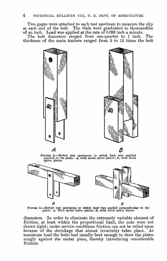
In practice, the splice plates used in joints, such as Figure 1, A, may be either of wood or of metal, according to choice or convenience. Both types were therefore used in the tests. The metal splice plates were one-fourth inch thick for bolts three-fourths inch or less in diameter and five-eighths inch thick for 1-inch bolts. Each wood plate was half the thickness of the main member. Two styles of test specimens are shown in Figure 2. A tensile load was applied to the metal plates of specimen A and the stick was held at its upper end by a through pin of relatively large diameter. To simplify the tests in which bolts of large diameters were employed, a compressive load was applied to the metal plates; when this was done, a small spacer block was bolted between the plates, near their ends, to help hold them in position. The application of a compressive load was found more convenient with specimens like Figure 2, B.
2 TRAYER^ G. W. BEARING STRENGTH OF WOOD UNDER STEEL AIRCRAFT BOLTS AND WASHERS AND OTHER FACTORS INFLUENCING FITTING DESIGN. Nat. Advisorv Com. Aeronautícs Tech. Notes 296, 25 p., illus. 1928.

THE BEABING STRENGTH OF WOOD UNDER BOLTS d
BEARING PERPENDICULAR TO THE GRAIN
The connections involving a bearing perpendicular to the grain are also commonly made in two ways, as illustrated in Figure 1, B. Accordingly the test specimens simulating such joints were made in two ways, as is shown in Figure 3. In one (fig. 3, A) a tensile load acting perpendicular to the grain was applied through metal plates one-quarter inch in thickness, while in the other (fig. 3, B) a com- pressive load was applied through wooden members each one-half the thickness of the main piece.
JBSJI^^ j^f^
• • • • • » I ^
M\-\<iqqç
FiGUBE 1.—Typical joints : A, Bearing parallel to the grain ; B, bearing perpendicular to the grain ; C, bearing at any angle with the grain ; a^ metal splice plates ; Ö, wood splice plates or divided member
GENERAL PROCEDURE
In all tests made primarily to determine the bearing stiength of wood under bolts of various diameters and lengths, only one bolt was used in each test specimen. On the other hand, in one series of tests made to determine the effect of shrinkage subsequent to as- sembly, four bolts were used. The specimens for this series were of green lumber, fastened with %-inch bolts. They were put away to season after assembly and later tested with the nuts untightened. In another series of tests, made to determine the proper margin and spacing, the number of bolts in each test specimen ranged from one to eight.
4 TECH]SriCAL BULLETIN 3 3 2^ U. S. DEPT. OF AGRICULTURE
Two gages were attached to each test specimen to measure the slip at each end of the bolt. The dials were graduated to thousandths of an inch. Load was applied at the rate of 0.026 inch a minute.
The bolt diameters ranged from one-quarter tO' 1 inch. The thickness of the main timbers ranged from 2 to 12 times the bolt
ß FIGURE 2.—Bolted test specimens to which load was applied
parallel to the grain : A, with metal splice plates "; B, with wood splice plates
A 3 FIGURE 3.—Bolted test specimens to which load was applied perpendicular to the
grain ; A, With metal splice plates ; B, with wood splice plates
diameters. In order to eliminate the extremely variable element of friction, at least within the proportional limit, the nuts were not drawn tight ; under service conditions friction can not be relied upon because of the shrinkage that almost invariably takes place. At maximum load the bolts had usually bent enough to draw the plates snugly against the center piece, thereby introducing considerable friction.

THE BEARING STRENGTH OF WOOD UNDER BOLTS 5
Bolt holes in metal plates were drilled. Those in wood members were bored cleanly and perpendicular to the surfaces involved, in a direction radial to the growth rings. The results presented in this bulletin apply only to holes spaced and aligned accurately.
Five species of wood ^ were used in the tests ; namely, Douglas fir, southern yellow pine, Sitka spruce, oak, and maple. In all except the one series of tests made to determine the effect of moisture changes, the test specimens were cut from seasoned lumber and the tests were conducted shortly after the joints had been assembled. The properties of the test material were determined by testing small control specimens cut from each piece.
PROPORTIONAL LIMIT OF A BOLTED JOINT
In discusssing the bearing strength of wood under bolts it is convenient to use the term proportional-limit stress, which is taken as the average stress under the bolt when the slip in the joint ceases to be proportional to the load. Although this point is regarded as a proportional limit, the joint will have a slight set on the removal of the load, chiefly because of the embedding of the bolts in the frayed wood fibers. Furthermore, the stress under the bolt is by no means uniform. What the actual stresses in the wood and in the bolt are when the proportional limit of the joint is reached is a question of academic interest, and so is the part that each plays in producing the proportional limit. The determination of the stress distribution in the wood and in the bolt is an extremely difficult mathematical problem. Approximate solutions have been obtained, as far as we are aware, only after various simplifying assumptions were made. How closely the calculated stress distributions deter- mined by means of these assumptions agree with the actual distribu- tions is a matter of conjecture.
The one important fact to be considered here is that at some load the slip in a bolted joint ceases to be proportional to the load. This slip is small, usually only a few hundredths of an inch. If the load at that point can be sustained repeatedly without an increase in slip or other evident injury, it can safely be regarded as a propor- tional limit. Repeated-load tests were made, and later discussion will show that the proportional-limit load of the joint can be sus- tained repeatedly without injury to the joint.
In the following discussion of the experimental study of the bolted joint the average proportional-limit stress is expressed as a ratio to a definite and known strength property of the wood. This scheme offers a simple and convenient method of obtaining safe working stresses from the results of hundreds of tests.
In presenting the test results the bearing strength of wood under bolts acting parallel to the grain is discussed first ; next, the bear- ing strength perpendicular to the grain; and, finally, the bearing strength at any angle between these two limits. The reason for this arrangement will become apparent as the discussion proceeds.
^ The names of species of wood in this bulletin are the standard common names employed hy the Forest Service.

6 TECHNICAL BULLETIÎT 3 3 2^ IT. S. DEPT. OF AGRICULTURE
BOLT-BEARING STRENGTH OF WOOD PARALLEL TO THE GRAIN
DISCUSSION OF TEST RESULTS
JOINTS WITH METAL SPLICE PLATES
The joint simulated in the tests employing metal splice plates, with the load acting parallel to the grain, is represented by Figure 1, A, a, and the type of test specimen is that shown in Figure 2, A. The thickness of the timbers in a direction parallel to the axis of the bolt was varied in such a way that the ratio of this dimension (Z) divided by the diameter of the bolt {D) was 2 for one set of speci- mens, 4 for the next set, and so on up to a value of 12. This definite stepping was selected for the reason that after considerable data for bolts of various diameters and lengths had been collected it became apparent that all of the results for a given value of L/D were similar for specimens of about the same quality and could be combined in an average stress figure. In other words, L/D was found to be the determining factor as regards stress. For example, the average proportional-limit stress in pounds per square inch under a %-inch bolt in a 3-inch piece was the same as that under a 1-inch bolt in a 6-inch piece, provided the two pieces did not differ greatly in quality. This fact was also clearly demonstrated in the tests of aircraft bolts previously made.
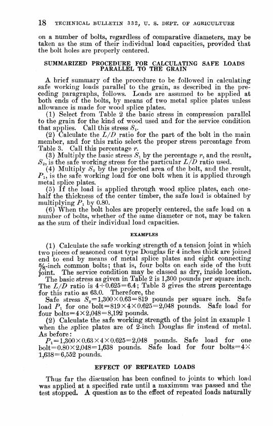
Figure 4 is a typical curve showing the relation between load on the bolt and slip in the joint. It is tor a joint made by connecting metal splice plates to a 2-inch timber by means of a single %-inch bolt. Load was applied parallel to the grain. The points on this curve fall along a straight line up to a load of 2,800 pounds, which is taken as the proportional limit. Readings were begun after a small initial load had been applied to take up all slack, which accounts for the fact that the first point is on the axis of ordinates.
The average proportional-limit stress obtained by dividing the proportional-limit load of 2,800 pounds by the projected bearing area of the bolt, of course, was not the actual stress at this load. At the edges of the timber the stress was much greater than this value and near the center it was much less. Furthermore, when the proportional-limit load marked on Figure 4 was reached, the bolt itself had probably reached its yield point. It is likely, then, that the effects of the stresses in the wood and in the bolt were com- bined in producing the apparent proportional limit of the joint. In addition, it is also probable that their relative importance in this regard varies with the L/D ratio of the joint. At any rate the average proportional-limit stress was found to drop off gradually as the L/D ratio was increased.
Figure 5, B, shows the variation in average stress at the propor- tional limit for the softwoods tested and Figure 6, B, for the hard- woods as L/D is varied from a negligible value to 12. The average proportional-limit bearing stress under a bolt is expressed as a percentage of the maximum crushing strength of the wood in which that bolt was used. Each symbol represents the average of the re-

THE BEARING STREÍTGTH OF WOOD tJN'DER BOLTS
suits for at least four and usually five tests, except for what corre- sponds to zero L/D.
The stress at what corresponds to zero LJD was obtained from the test of specimens like Figure Y, A. Uniform pressure was applied to the bolt through a heavy plate in order to eliminate any bending of the bolt. The value plotted at zero LJD in Figure 5 is the average
5600
4800
I
vj
4000
3 ZOO
2400
1600
800
O o
lOO
PROPORTíONfiL LIMIT
O O
0.04 0.08 O.IZ 0.16 SLIP IN JOINT (INCH)
0.Z0
FiGUEB 4.—The relation between load parallel to the grain and slip in the joint for an individual test specimen
of 55 tests, and the corresponding value in Figure 6 is the average of 50 tests.
Although a single curve was drawn through the plotted data on Figures 5 and 6, theoretically more than one curve would be re- quired when the material in the test speciments differed markedly in quality. This statement depends upon the soundness of the previous deduction that the strengths of the bolt and of the wood are com-

8 TECHNICAL BULLETIN 3 3 2^ U. S. DEPT. OF AGRICULTURE
bined in producing the apparent proportional-limit strength of the joint. A careful scrutiny of the plotted data may throw some light on this deduction.
Especially in curve B of Figure 5, a considerable divergence in the plotted points occurs at all LJD ratios of from 4 to 12. Imme- diately above and below each group of points is given the maximum crushing strength, in pounds per square inch, of the test material from which the extreme values were obtained. The average crush- ing strength of all the specimens tested at LJD ratios of from 4 to 12 (fig. 5, B) was 5,390 pounds per square inch. In general, when a test piece was below this figure in quality the ratio of its average
FiQUKB 5.—For conifers, the relation between average bolt-bearing stress, expressed in terms of the maximum crushing strength of the wood parallel to the grain, and the ratio of the length of the bearing (Zy) in the main member to the diameter of the bolt (D) : A, Average stress at a slip of 0.1 inch ; B, average stress at the pro- portional limit
proportional-limit bolt-bearing stress to its maximum crushing strength was above the curve. Likewise, when a piece was stronger the same ratio for it was below the curve.
The general tendency for the ratio of the average proportional- limit bearing stress to the crushing strength of a test piece to vary with quality of material was even more clearly shown in the tests perpendicular to the grain. The material for such tests could well be divided into two distinct classes, one approximately double the compressive strength of the other. The results of such division appear in Figure 12. Without attempting to explain the ordinate axis of Figure 12 at this time, it may be said that the curves show the general relation between the average proportional-limit joint stress perpendicular to the grain and the LJD ratio. For a diver- gence in quality so extreme as this, two curves were required to rep-

THE BEARING STRENGTH OF WOOD UNDER BOLTS 9
resent the general trend, one for each class of material. All these facts tend to substantiate the conclusion that, except for small L/D ratios, the bending strength of the bolt as well as the crushing strength of the wood is intimately associated with the proportional- limit strength of the joint.
It so happens that beyond an L/D ratio of about 5^ the average proportional-limit stress, as represented by the B curves of Figures 5 and 6, drops off at the same rate that the L/D ratio increases.
6 7 % RATIO
FiGüEB 6.—For hardwoods, the relation between average bolt-bearing stress, expressed m terms of the maximum crushing strength of the wood parallel to the grain, and the ratio of the length of the bearing (L) in the main member to the diameter of the bolt (D) : A, Average stress at a slip of 0.1 inch ; B, average stress at the pro- portional limit
This means that for all L/D ratios greater than ^y^ the propor- tional-limit load remains constant for a bolt of a given diameter.
How the curves of Figures 5 and 6 were actually fitted to the plotted data is explained in the appendix. The relationship between proportional-limit load and L/D is also shown there graphically.
Although the B curves of Figures 5 and 6 have the same general shape, the one representing the variation in average proportional- limit bolt-bearing stress with L/D for coniferous woods is lower than
128843''—32 2

10 TECHlSriCAL BULLETIN 3 3 2^ U. S. DEPT. OF AGKICULTURE
the corresponding curve for hardwoods. The curve for conifers reaches only 64 per cent of the maximum crushing strength of the wood, for extremely small L/B ratios, while the one for hardwoods reaches 80 per cent. Throughout the entire LJD range this propor- tional difference is about the same. Only a small part of it can be accounted for by the slight difference in the average strength of the test specimens of the two groups of woods. Seemingly the significant difference is due to the fact that the across-the-grain properties of the hardwoods as a group are relatively higher, in comparison with their compressive strength along the grain, than are those of the conifers. It is apparent that when pressure is applied to the cylin- drical bolt this pressure is resisted not only by components acting parallel to the grain but also by other components acting perpendicu- lar to the grain. Further, it is also possible that, because of a dif- ferent structural arrangement of the two kinds oi wood, a different distribution of the stress in the wood under the bolt occurs.
FIGURE 7.—Test specimens to which load was applied through a plate in order to eliminate all bending of the bolt : A, Load parallel to the grain ; B, load perpendic- ular to the grain
The slip in the joint at the proportional-limit load was about 0.02 inch for 14-inch bolts, 0.02 to 0.03 inch for i/^-inch bolts, and about 0.04 inch for %-inch and 1-inch bolts. For any given diameter of bolt the slip at this load remained fairly constant for LJB ratios of from 4 to 12. At an LJB ratio of 2 the bending of the bolt appeared to be of little if any importance, and the slip was usually somewhat less than for larger ratios. The increase in proportional-limit slip with diameter of bolt also points to the conclusion that the bending strength of the bolt has a pronounced effect upon the proportional- limit strength of the joint, because for any given L/B ratio a large bolt must bend farther than a small one to reach a given bending stress.
The average stresses associated with a slip of 0.10 inch follow the A curves of Figures 5 and 6. These curves are higher than the B curves of the same figures^ but have the same general shape. Plotting

THE BEARINO STRENGTH OF WOOD UNDER BOLTS 11
values for still larger distortions, an upper limit of average stress is soon reached, one that is about 100 per cent of the maximum crushing strength for conifers and 140 or 150 per cent, or even more, for hardwoods. In other words, the maximum loads in the entire L/D range examined, when divided by the projected area of the bolt, yield calculated average stresses that are about equal to the crushing strength of the wood parallel to the grain for conifers and con- siderably greater than that strength for hardwoods. Unlike the slip at proportional limit, which remained fairly constant for all L/D ratios, however, the slip at maximum load increased greatly as the L/D ratio was made larger.
Although the strength properties of the bolt control to a con- siderable extent the magnitude of the proportional-limit load on a bolted joint, within the limits of the investigation the maximum load appeared to be controlled almost entirely by the strength characteris- tics of the wood ; this fact is important. In Figure 5, B, the highest point on the curve at an L/D ratio of 4 is the average for spruce specimens the maximum compressive strength of which was 4,656 pounds per square inch. The lowest point for spruce at this L/D ratio represents material the compressive strength of which was 6,296 pounds per square inch. The average stress under the bolt at maximum load, however, was 95.8 per cent of the maximum crushing strength of the low-strength material and 93.2 per cent of the high- strength material.
JOINTS WITH WOOD SPLICE PLATES
Figure 1, A, 5, represents the joint simulated in the tests of speci- mens having wood splice plates and Figure 2, B, shows the type of test specimen. The thickness of the center member was varied from 2 to 6 inches by 1-inch increments, and only one i^'ii^^^h bolt was used in each test specimen. The L/D ratio, therefore, varied from 4 to 12 in acordance with the procedure followed in the tests with metal plates. Each outside piece was always made half the thick- ness of the center piece.
It was found that the average proportional-limit stress values again grouped themselves along a curve like the B curves of Figures 5 and 6 and that the slip associated with these values was about 0.035 inch. The stresses, however, were somewhat less than those obtained when metal splice plates were used. Table 1 shows how the results of these tests compare with the results of corresponding tests employ- ing metal plates. The proportional-limit values for wood plates, ex- pressed as ratios to the crushing strengths, average 87 per cent of the corresponding metal-plate values for the two coniferous woods, and 75 per cent for the two hardwoods, over an L/D range of 4 to 12. The table discloses the fact, however, that the coniferous woods tested with metal plates averaged 23 per cent better in compressive strength than those tested with wood plates. The significance of this fact was pointed out in a foregoing statement that the ratio of the average proportional-limit stress of the joint to the maximum compressive strength of the main timber was found to be higher for a low-strength piece than for a high-strength one. This would tend to make the wood-plate values high in comparison with the metal-

12 TECHNICAL BULLETIN 3 3 2^ U. S. DEPT. OF AGRICULTURE
plate values. The situation for the hardwoods listed in Table 1 is reversed as regards quality of material, which tends to make the wood- plate values low. It appears to be a logical conclusion that the average of the 87 and the 75 per cent ratios would very nearly repre- sent the true relation between the average proportional-limit stresses for joints made with wood splice plates and for those made with metal splice plates. This average is 81 per cent, which for conven- ience will be taken as 80 per cent.
TABLE 1.—The comparative proportional-limit strength parallel to the grain of l)Olted joints having woocÙ splice plates and those having metal splice plates
Ratio of bearing
length of bolt in main member to diameter
of bolt (L/D)
Wood splice plates Metal splice plates
Species of wood crushing strength of main member
Propor- tional-limit
stress of joint in terms of
maximum crushing strength of main member
Maximum crushing strength of main member
Propor- tional-limit
stress of joint in terms of
maximum crushing strength of main member
Ratio of column 4 to column 6 values
1 2 3 4 5 6 7
Sitka spruce 4 6 8
10 12 4 6 8
10 12
Pounds per square inch
3,820 4,665 4,038 4,501 4,141 4,809 5,345 4,950 4,682 4,959
0.427 .284 .239 .177 .159 .388 .298 .227 .169 .145
Pounds per square inch
5,186 6,375 4,976 6,155 5,088 5,715 5,865 5,861 5,690 5,717
0.525 .311 .265 .187 .161 .476 .340 .251 .212 .192
0.813 913 Do __ -_ --
Do _ .902 .946 .988 815
Do __. Do _
Southern yellow pine Do - _ - 876 Do 904 Do 797 Do _ - - - .755
Average _ - 4,591 5,663 871
Maple 4 6 8
10 12 4 6 8
10 12
5,488 5,391 5,866 6,266 6,616 4,892 5,703 5,449 5,478 5,097
0.374 .302 .252 .173 .142 .430 .290 .213 .181 .152
4,145 4,690 4,232 4,645 4,530 4,884 4,096 4,122 4,450 4,442
0.533 .340 .296 .237 .171 .593 .406 .328 .256 .213
0.701 .888
851 Do Do _. ._ ___ . __. _- Do .730
.830 725
Do Oak
Do -- -_ _ - --_ _ 714 Do .649
.707 714
Do Do
Average _. 5,625 4,424 751
Grand average 5,108 5,044 .811
SAFE WORKING STRESSES PARALLEL TO THE GRAIN FOR COMMON BOLTS
VARIATION WITH L/I>
If the B curves of Figures 5 and 6 are replotted with the ordinates for extremely small L/D ratios taken as 100 per cent, both curves reduce to Figure 8, A. This curve then represents the percentage variation in average proportional-limit joint stress with variation in L/D for material not differing greatly in strength from the average of that tested. Previous discussion has indicated that, for material appreciably lower in strength than this average, the curve would

THE BEARING STREITGTH OF WOOD UNDER BOLTS 13
drop off less rapidly with increasing L/D ratios and for material appreciably higher in strength it would drop off more rapidly. In any event, if ^afe working stresses were based solely on the average proportional-limit joint stresses they would drop off with increasing L/D ratios in accordance with Figure 8, A, or at least in accordance with a slight modification of it.
^€0
Ï
A
X V
3 \ --^ \ \ \ \ s^ s
X "^
^^-^, " ^ ̂ --
0 I 2 3 4 5 6 7 Q 9 10 II IZ 13 % RATIO
FIGURE 8.—For both conifers and hardwoods, variation in average bolt-bearing stress parallel to the grain with the ratio of the length of the bearing (I/) in the main member to the diameter of the bolt (D) : A, Average proportional-limit stress; B, recommended modification for actual use
It has been shown that the average stress under the bolt at maxi- mum load does not drop off in this fashion, but remains fairly con- stant, which means that the gap between the proportional-limit load and the maximum load widens as L/D increases. Therefore, the same degree of safety would not be maintained at all i/D ratios if safe stresses were varied in accordance with the average proportional- limit stresses.
The Forest Products Laboratory recommends that safe bolt-bearing stresses be based largely on average proportional-limit stresses. In order to insure sufficient safety at small L/D ratios, however, the curve representing variation in safe stress should be below the curve representing variation in average proportional-limit stress at small L/D ratios, although coinciding with it in the greater L/D ratios. The modification can best be explained by referring again to Figure 8, A. This curve is dropped 20 per cent from its starting point to an L/D ratio of 2 and is dropped a proportionately less amount from there to an L/D of 5. From this point on no change is made. The new curve. Figure 8, B, consisting of the dotted portion on the left

14 TECHNICAL BULLETIN 3 32, U, S. DEPT. OF AGRICULTURE
and the full line on the right, represents the recommended variation in working stress. The curve can be more conveniently used if the scheme of reducing it to a percentage basis is again followed and the extreme left-hand portion, now 80 per cent, is taken as 100 per cent. Figure 9, C, shows the curve changed to this basis.
no
I 60
i
.30
20
~^ ?\ X \ \ \
X \^ UP 1
\
\: ̂ K OUP z
N
^
S
:^ -CROU P 3
^ ^^ ^^
:::^
9- 10
0 1 2 3 4 s 6 7 6 9 fO it U 13
FIGURE 9.—The percentages recommended for use with basic stresses parallel to the grain in calculating safe working stresses for both conifers and hardwoods of Table 2 : A, group 1 woods ; B, group 2 Woods ; C, group 3 woods
Figure 9, C, is simply a graphical representation of the proposed variation in working stress with L/D ; to supply safe working stresses it must be used in conjunction with l3asic stresses determined in the investigation but not yet presented. The scheme for selecting basic stresses, which is proposed on page 15, introduces a factor that places the recommended safe stresses well below the proportional-limit stresses at all values of L/D. These working stresses will vary with the proportional-limit stresses, but will not even approach them in actual magnitude.
The proposed variation in working stress shown by Figure 9, C, applies only to wood having a compressive strength approximately the same as that used in the tests. The strength properties of our common woods differ widely, and for that reason this curve can not be used for all woods without modification.
Before any scheme of modification can be suggested the range in magnitude of basic stresses adopted for the different species must be considered. The stresses recommended by the Forest Products Laboratory and the method of obtaining them from general strength data already published by the laboratory are set forth in the follow- ing discussion.

THE BEAÏUÎTG STRENGTH OF WOOD TTNDEE BOLTS 15
DETERMINATION OF BASIC STRESSES
In general the scheme for arriving at basic bolt-bearing stresses parallel to the grain was to modify the average ultimate crushing strength parallel to the grain of small, clear, green specimens as indicated in the following steps :
(1) Multiplication by 0.80 for coniferous woods and by 0.75 for hardwoods to allow for the effect of long-time loading. These values, determined by the Forest Products Laboratory in previous work, represent the relation of the proportional-limit strength to the ulti- mate crushing strength parallel to the grain as obtained in a stand- ard test of only a few minutes' duration. Under long-time loading failure would be expected to occur at approximately the proportional limit obtained in a test of short duration.
(2) A second multiplication by 0.8Ö for coniferous woods because the proportional-limit curve of Figure 5 for conifers is 20 per cent lower throughout the entire L/D range than the corresponding curve of Figure 6 for hardwoods.
(3) A further multiplication by 1.20 to allow for an increase in strength with drying. The actual increase is more than 20 per cent, but there is always some checking accompanying the seasoning that partly offsets the increase in strength.
(4) Division by 2.25 to cover both variability and a reasonable factor of safety.
Although this method was followed in general, minor departures from it were necessary in setting up stresses for particular species that have unusually low across-the-grain properties in comparison with their compressive strength along the grain, or that exhibit ab- normal tendencies in drying.
In Table 2 commonly used conifers and hardwoods have been listed in three groups each. The average stress for each group ob- tained by following the foregoing procedure is given in the third column of the table. The stresses for bearing at right angles to the grain, given in the last column, will be discussed later.
The values of Table 2 need not be reduced for grade. However, they apply only to seasoned timbers used in a dry, inside location. Modifications necessary when the condition of service is more severe are explained in the footnote to the table.
MODIFICATION OF EXPERIMENTALLY DETERMINED CURVES FOR CLASS OF MATERIAL
A survey of the test results has shown that in the larger i/Z> ratios a relatively higher proportional-limit joint strength was ob- tained for material low in strength than for material of high strength. For this reason, in the larger L/D ratios the conifers and hardwoods of groups 1 and 2, Table 2, can be allowed percentages of their basic stresses higher than those represented by Figure 9, C, which are restricted to the group 3 woods. This curve does apply strictly to group 3 woods, because all of the test material except spruce was in that class. The spruce used, however, was selected aircraft stock having a compressive strength parallel to the grain corresponding more closely to that of the group 3 conifers than to that of either group 1 or group 2.

16 TECHNICAL BULLETIN 3 3 2^ U. S. DEPT. OF AGRICULTURE
TABLE 2.—Basic stresses for calculating safe loads for bolted joints *
Species of wood
Basic stress
Group Parallel to the grain
Perpen- dicular to the grain
Softwoods: [■ Cedar, northern and southern white...
Pounds per square inch
800
1,000
1,300
925
1,200
1,500
Poundsper square inch
Fir, balsam and commereial white 1 \ Hemlock, eastern... ._..... .__ 150
Pine, ponderosa, sugar, northern white, and western white Spriifie, T^TigfilmaTiTi, rfid, Siti^^a, arid whit-e Cedar, Alaska, Port Orfórd, and western red Douglas fir (Rocky Mountain type) . _. ._ - 2 Hemlock, western ._ 200 Pine, Norway. . . -
( Cypress, southern Douglas fir (coast type) __ __. Larch, western _._ ___ . 3 Pine, southern yellow ._ .. ___ ___ _ _._ _ 275 Redwood- _ _ . _ _. Tamarack
Hardwoods: / Ash, black-
Aspen and largetooth aspen Basswood -- -
1 Birch, paper... ._ 175 Chestnut Cottonwood, black and eastern Yellow poplar _ ...
Í Maple (soft), red and silver 2 Elm, American and slippery .. .._ .-_ .__ _. _ .. _.
Gum, black, red, and túpelo 250 Sycamore ... _ _ ___ __
/ Ash, commercial white Beech .- _ . _ _ _. __. .. _. Birch, sweet and yellow
3 TCITTI, rnfilr 400 Hickory, true and pecan 1 _- - Maple (hard), black and sugar .._ . Oak, commercial red and white
1 These stresses, when used in conjunction with Tables 3 and 4, give safe bolt-bearing stresses. They apply to seasoned timbers used in a dry, Inside location. For other conditions, reduce each stress as follows : When the timbers are occasionally wet but quickly dried, use three-fourths of the stress listed ; if damp or wet most of the time, use two-thirds.
The relative position of the data plotted in Figures 5 and 12 sup- plies a basis for adjusting the group 3 percentages for application to the other two groups. An analysis of these data, especially those shown in Figure 12, discloses the fact that in the large L/D ratios the average proportional-limit stress for a low-strength piece is rela- tively higher than that of a high-strength piece, and that the order of their relative magnitude corresponds approximately to the square root of the inverse ratio of the respective crushing strengths oi the two pieces. Stated in another way, if the crushing strength of one timber is half that of another timber, the average proportional-limit bolt-bearing stress of the first timber, expressed as a ratio of its own crushing strength, will be approximately the square root of two times the average proportional-limit bolt-bearing stress of the second tim- ber, expressed as a ratio of its crushing strength. Using this as a basis of adjustment, the portions of the two upper curves of Figure 9 from an L/D of 6 to an L/D of 13 were obtained. As an illus- tration, the ordinates of curve A in this range are those of curve C multiplied by the square root of 1.62, since the basic stresses parallel to the grain given in Table 2 for group 3 woods are 1.62 times those of the corresponding group 1 woods.

THE BEARING STRENGTH OF WOOD UNDER BOLTS 17
An earlier part of this bulletin has shown that at small L/B ratios the average proportional-limit stress bears the same relation to the maximum crushing strength for all classes of material within either of the two main divisions of species. Hence no adjustment of work- ing-stress percentages should be made for L/D ratios of about 3 and less.
In completing curves A and B of Figure 9 from an L/D of 3 to an L/B of 6, they were simply filled in to agree with the general form of the lower curve.
The three curves of Figure 9 give, for Z/Z> ratios up to 13, the per- centage correction to be applied to the l3asic bolt-bearing stresses, parallel to the grain, for the three groups into which the common woods have been divided. Percentages taken from these curves are listed in the left-hand portion of Table 3.
TABLE 3.—Percentage of 'basic stress parallel to the groAn'^ for calciilatinç safe bearing stresses under bolts
Length of bolt in main
Percentage of basic stress for—
member Co] mmon bolts 2 High-strength bolts 3 1 divided by its diam- eter Group 1 Group 2 Group 3 Group 1 Group 2 Group 3
{LID) woods woods woods woods woods woods
1.0 100.0 100.0 100.0 100.0 100.0 100.0 1.5 100.0 100.0 100.0 100.0 100.0 100.0 2.0 100.0 100.0 100.0 100.0 100.0 100.0 2.5 100.0 100.0 99.7 100.0 100.0 100.0 3.0 100.0 100.0 99.0 100.0 100.0 100.0 3.5 100.0 99.3 96.7 100.0 100.0 99.7 4.0 99.5 97.4 92.5 100.0 100.0 99.0 4.5 97.9 93.8 86.8 100.0 100.0 97.8 5.0 95.4 88.3 80.0 100.0 99.8 96.0 5.5 91.4 82.2 73.0 100.0 98.2 93.0 6.0 85.6 75.8 67.2 100.0 95.4 89.5 6.5 79.0 70.0 62.0 98.5 92.2 85.2 7.0 73.4 65.0 57.6 95.8 88.8 81.0 7.5 68.5 60.6 53.7 92.7 85.0 76.8 8.0 64.2 56.9 50.4 89.3 81.2 73.0 8.5 60.4 53.5 47.4 85.9 77.7 69.6 9.0 57.1 50.6 44.8 82.5 74.2 66.4 9.5 54.1 47.9 42.4 79.0 71.0 63.2
10.0 51.4 45.5 40.3 75.8 68.0 60.2 10.5 48.9 43.3 38.4 72.5 64.8 57.4 11.0 46.7 41.4 36.6 69.7 61.9 54.8 11.5 44.7 39.6 35.0 66.8 59.2 52.4 12.0 42.8 37.9 33.6 64.0 56.7 50.2 12.5 41.1 36.4 32.2 61.4 54.4 48.2 13.0 39.5 35.0 31.0 69.1 52.4 46.3
1 The product of the basic stress parallel to the grain selected from Table 2 and the percentage for the particular LjD ratio and species group, taken from this table, is the safe working stress at that ratio for joints with metal splice plates. When wood splice plates are used, each one-half the thickness of the main timber, 80 per cent of this product is the safe working stress.
2 Bolts having a yield point of approximately 45,000 pounds per square inch. 3 Bolts having a yield point of approximately 125,000 pounds per square inch.
With the preceding explanation, Tables 2 and 3 supply the in- formation needed to calculate the safe loads parallel to the grain for bolts of diameters and lengths that are usual in commercial work. The tabular values are solely for load applied to both ends of the bolt or bolts. The value that is safe when load is applied to only one end of a bolt is half that for 2-end application, as explained later in the discussion of details of design. Further, the safe load
128843**—32-—-3
18 TECHNICAL BULLETIN 3 3 2^ U. S. DEPT. OE AGRICULTUEE
on a number of bolts, regardless of comparative diameters, may be taken as the sum of their individual load capacities, provided that the bolt holes are properly centered.
SUMMARIZED PROCEDURE FOR CALCULATING SAFE LOADS PARALLEL TO THE GRAIN
A brief summary of the procedure to be followed in calculating safe working loads parallel to the grain, as described in the pre- ceding paragraphs, follows. Loads are assumed to be applied at both ends of the bolts, by means of two metal splice plates unless allowance is made for wood splice plates.
(1) Select from Table 2 the basic stress in compression parallel to the grain for the kind of wood used and for the service condition that applies. Call this stress S^.
(2) Calculate the L/D ratio for the part of the bolt in the main member, and for this ratio select the proper stress percentage from Table 3. Call this percentage r,
(3) Multiply the basic stress S^ by the percentage /•, and the result,. S2, is the safe working stress for the particular L/D ratio used.
(4) Multiply S2 by the projected area of the bolt, and the result. Pi, is the safe working load for one bolt when it is applied through metal splice plates.
(5) If the load is applied through wood splice plates, each one- half the thickness of the center timber, the safe load is obtained by multiplying Pi by 0.80.
(6) When the bolt holes are properly centered, the safe load on a number of bolts, whether of the same diameter or not, may be taken as the sum of their individual load capacities.
EXAMPLES
(1) Calculate the safe working strength of a tension joint in which two pieces of seasoned coast type Douglas fir 4 inches thick are joined end to end by means of metal splice plates and eight connecting %-inch common bolts ; that is, four bolts on each side of the butt joint. The service condition may be classed as dry, inside location.
The basic stress as given in Table 2 is 1,300 pounds per square inch. The L/D ratio is 4-^0.625 = 6.4; Table 3 gives the stress percentage for this ratio as 63.0. Therefore, the
Safe stress >S'2=1,300X0.63=819 pounds per square inch. Safe load Pi for one bolt=819X4X0.625=2,048 pounds. Safe load for four bolts=4 X 2,048 = 8,192 pounds.
(2) Calculate the safe working strength of the joint in example 1 when the splice plates are of 2-inch Douglas fir instead of metaL A. s before *
Pi = 1,300X0.63X4X0.625=2,048 pounds. Safe load for one bolt=0.80X2,048=1,638 pounds. Safe load for four bolts=4X 1,638=6,552 pounds.
EFFECT OF REPEATED LOADS
Thus far the discussion has been confined to joints to which load was applied at a specified rate until a maximum was passed and the test stopped. A question as to the effect of repeated loads naturally

THE BEARING STRENGTH OF WOOD UNDER BOLTS 19
arises. Since in this investigation safe working loads have largely- been built around proportional-limit load^, it became especially im- portant to learn whether such loads could be sustained repeatedly without appreciable increase in the slip of the joint. Accordingly, a series of tests was made on a joint in which metal splice plates were attached to a 3-inch spruce timber by mean^ of a i/^-inch bolt. The results are represented in Figure 10, C. This curve shows the ac- cumulated set in the joint resulting from repeated loads, exclusive of that which existed when the first load was removed.
The slip associated with the first proportional-limit loading was approximately 0.025 inch. When the load was removed after the first test, a set of about 0.009 inch remained. The set shown by Figure
0.010
Î t; 0.006
TEST STOPP ED OV ■R WEt "/f EAfû
KHMH o^<x .^ooí
,oo»' >ooo*
,ooo* oo*
1 < o«' • 0
lo°
^ 0.005
u, 0.004
S 0.003 •**
çj O.00Z lu
1 0.001
o* o
o
ó
o
ß • •• • ••' Tí ST ST
• •• OPPEP
..Ij OVERN
• • •.< &HT
o • ••; l00° 1 roooí
• • •< • •• C
booo¿
••• ^ 0 o o i
1 • • *
Uoo< f°00i xxxx _
o ^^^^^-öi ooo( ooo( looo^ ?o°®*
O O 16 ¿4 3Z 40 48 66 64 72 60 66 96 104 112 120- NUMBER OF REPEATED LOADS PARALLEL TO THE GRAIN
FIGURE 10.—The relation between accumulated set in a joint of spruce and number of repeated loads parallel to the grain : A, Loads 50 per cent greater than the pro- portional limit : B, loads 25 per cent greater than the proportional limit ; C, pro- portional-limit loads
10, C, is what accumulated in addition to this 0.009 inch as the loads were put on and removed. Only the results for every other test are shown. These results indicate clearly that no appreciable set comes from repeating proportional-limit loads.
Figure 10, B, shows the effect of repeating a load 25 per cent in excess of the proportional-limit load of a similar joint. Again the accumulated set shown is exclusive of that which remained when the first load was removed. Here the accumulated set increases very slightly.
Figure 10, A, shows the effect of repeating a load 50 per cent in excess of the proportional limit. It is apparent that repeated loads of this magnitude would soon produce harmful effects.
Another series of tests, the results of which are not recorded in Figure 10, showed that repeated proportional-limit loads, following a single overload of 50 per cent beyond the proportional limit, pro- duced no increase in accumulated set above that which remained after

20 TECHNICAL BULLETIN 3 3 2^ U. S. DEPT. OF AGRICULTUEE
the removal of the 50 per cent overload. Still another series showed that repeated loads 25 per cent in excess of the proportional limit, following a single overload of 50 per cent beyond the proportional limit, did produce a slight increase in accumulated set beyond that which existed after the removal of the 50 per cent overload. Al- though the increase was extremely slight after several hundred repetitions of the load, the tendency to increase was still apparent.
The general conclusion drawn from these tests is that no harmful slippage in the joint will result from repeating the proportional- limit load, but that constant repetition of loads in excess of it may be dangerous.
SAFE WORKING STRESSES PARALLEL TO THE GRAIN FOR BOLTS OF HIGH STRENGTH
As already mentioned, the detailed information in this bulletin applies only to bolts with a strength at the yield point of approxi- mately 45,000 pounds per square inch. Likewise, the percentage variation in working stress represented by Figure 9 applies strictly to bolts of this quality. A previous study of aircraft bolts with a yield-point strength of approximately 125,000 pounds per square inch showed that for extremely small LJI) ratios the proportional limits of the joints were the same as those for low-strength bolts, but that for the larger ratios they were considerably higher. The fact that the bending strength of the bolt is of great importance in relation to the proportional-limit strength of the joint explains thiö. It is a natural conclusion that working loads higher than those reached by following the procedure suggested in the foregoing should be per- mitted for bolts that have a yield-point strength of more than 45,000 pounds per square inch.
Figure 11, B, shows the same recommended variation in working stress with L/D as that given in Figure 9, C. By following the same method that was used in obtaining Figure 9, C, the curve, Figure 11, A, is found to represent the corresponding variation for bolts that have a yield-point strength of 125,000 pounds per square inch.
Percentages taken from Figure 11, A, are listed in the right-hand portion of Table 3 for group 3 woods. Adjustments were made for the species in groups 1 and 2 according to the procedure followed for common bolts. The adjusted values also appear in the right-hand portion of Table 3. These values and the stresses of Table 2 are recommended when bolts that have a yield point of approximately 125,000 pounds per square inch are used in engineering structures other than aircraft. The whole scheme of insuring reasonable safety in a bolted joint in an airplane is different from that generally em- ployed in other fields of construction. For this reason ño one should assume that, because these high-strength bolts have been referred to as aircraft bolts, the design procedure and the working stresses would apply to that type of construction. A publication on the use of wood in this field has already been referred to.^
Just what the working loads should be for bolts of a quality be- tween 45,000 and 125,000 pounds per square inch at the yield point is not known. Probably, however, no appreciable error would be introduced by direct interpolation.
* See footnote 2, p. 2.

THE BEARING STRENGTH OF WOOD UNDER BOLTS 21
BOLT-BEARING STRENGTH OF WOOD PERPENDICULAR TO THE GRAIN
DISCUSSION OF TEST RESULTS
JOINTS WITH METAL SPLICE PLATES
The joint simulated in the tests with the thrust applied perpendic- ularly to the grain through metal splice plates is represented by Figure 1, B, a^ and the type of test specimen is shown in Figure 3, A. The thickness of the test specimens in the direction parallel to the axis of the bolt was varied in such a way that the ratio of this dimension (Z) to the diameter of the bolt (Z>) was 4 for one set of specimens, 6 for the next set, and so on up to a value of 12. The
ct 90 ^ V "^
\
1 \
\ \
V \
\
\
\ >
\ "^
\ ^^ "^
..^
0 I Z 3 4 5 6 7 a 9 10 II 12 13 % RATIO
FIGURE 11.—The percentages recommended for use with basic stresses parallel to the grain in calculating safe working stresses for group 3 conifers and hardwoods of Table 2 : A, For bolts having a yield point of 125,000 pounds per square inch ; B, for a yield point of 45,000 pounds per square inch
tests with bearing parallel to the grain demonstrated that the L/D ratio determined the variation in the average proportional-limit stress, regardless of the diameter of the bolt. Since this fact, previ- ously established in the tests of aircraft bolts already mentioned, was borne out conclusively in the first tests of common bolts, the tests with bearing perpendicular to the grain were limited to the one-half inch size. The variation of average stress with L/D is now so defi- nitely established that the results may be applied with confidence to bolts of any commercial diameter.
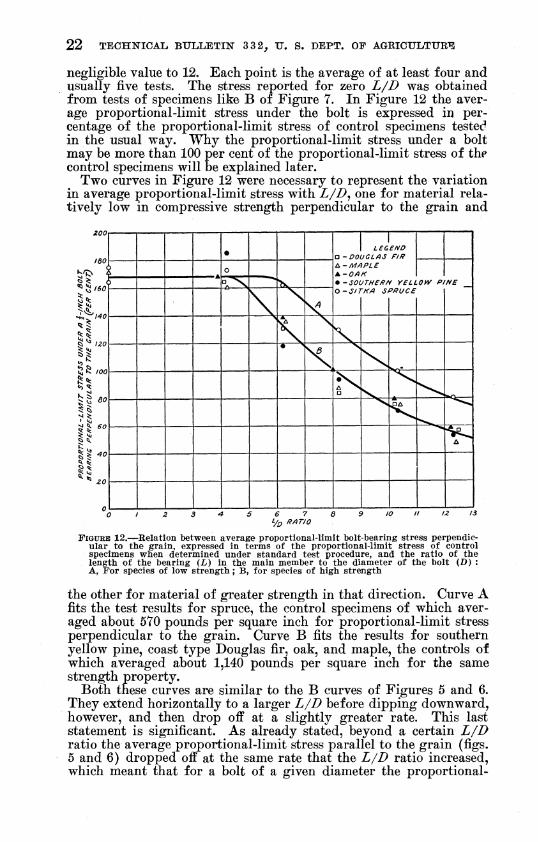
Figure 12 shows the variation in the average stress at proportional limit in bearing perpendicular to the grain as L/D is varied from a
22 TECHNICAL BULLETIN" 3 3 2, U. S. DEPT. OF AGBICULTURT3
negligible value to 12. Each point is the average of at least four and usually five tests. The stress reported for zero L/D was obtained from tests of specimens like B of Figure 7. In Figure 12 the aver- age proportional-limit stress under the bolt is expressed in per- centage of the proportional-limit stress of control specimens tested in the usual way. Why the proportional-limit stress under a bolt may be more than 100 per cent of the proportional-limit stress of the control specimens will be explained later.
Two curves in Figure 12 were necessary to represent the variation in average proportional-limit stress with L/D^ one for material rela- tively low in compressive strength perpendicular to the grain and
FIGURE 12.—Relation between average proportional-limit bolt-bearing stress perpendic- ular to the grain, expressed in terms of the proportional-limit stress of control specimens when determined under standard test procedure, and the ratio of the length of the bearing (L) in the main member to the diameter of the bolt (D) : A, For species of low strength ; B, for species of high strength
the other for material of greater strength in that direction. Curve A fits the test results for spruce, the control specimens of which aver- aged about 570 pounds per square inch for proportional-limit stress perpendicular to the grain. Curve B fits the results for southern yellow pine, coast type Douglas fir, oak, and maple, the controls of which averaged about 1,140 pounds per square inch for the same strength property.
Both these curves are similar to the B curves of Figures 5 and 6. They extend horizontally to a larger L/D before dipping downward, however, and then drop off at a slightly greater rate. This last statement is significant. As already stated, beyond a certain L/D ratio the average proportional-limit stress parallel to the grain (figs. 5 and 6) dropped off at the same rate that the L/D ratio increased, which meant that for a bolt of a given diameter the proportional-

THE BEARIN-G STRENGTH OF WOOD UNDER BOLTS 23
limit load increased up to this particular L/D ratio and then re- mained constant. (Fig. 16, B.) The situation is somewhat dif- ferent for bearing perpendicular to the grain. Here the propor- tional-limit load for a bolt of given diameter increased up to a certain L/D ratio and then slowly dropped off in the larger L/D range. (Fig. 17, A and B.)
The distribution of the data plotted in Figure 12 shows even more clearly than the distribution in Figure 5 that a relatively higher average proportional-limit stress is obtained with wood low in strength than with material of high strength. This in turn again points to the fact that the strength of the bolt in a measure deter- mines the proportional-limit strength of the joint.
The slip in the joint associated with the average proportional-limit stresses plotted in Figure 12 ranged from about 0.025 to 0.030 inch.
No clearly defined maximum loads were obtained in the tests. Usually the test specimens failed under combined tension across the grain and shear, ultimately splitting and shearing from end to end. The average stress under the bolt when this type of failure occurred was much farther above the average proportional-limit stress at large L/D ratios than it was at small L/D ratios. This in a way corresponds to the greater gap between maximum stress and propor- tional-limit stress that obtained at large L/D ratios than at small ratios when loads were applied parallel to the grain.
In order to explain why the average proportional-limit stresses in Figure 12 exceed the proportional-limit stresses of the control speci- mens in some instances, it is necessary to outline briefly the standard- test procedure followed. In this procedure a plate 2 inches wide is placed across the middle of a test specimen 6 inches long, so that only 2 inches of the 6-inch length is compressed. When load is applied to the plate, the fibers along its edges are thrown into bending and tension, with the result that the observed proportional-limit stress is higher than it would be if the whole specimen were covered. Since this edge effect remains constant, the percentage increase that it causes in the average calculated stress varies as the width of plate is changed, naturally becoming greater at small widths. A similar effect is observed when the bolt diameter is varied. In order to measure this variable, a series of tests, employing bolts of various diameters and test specimens like Figure 7, B, was run. A load uniformly distributed along their length was applied to the bolts, which rested in the half-round holes. The proportional-limit stress under the bolts, expressed as a ratio to the proportional-limit stress of the material obtained by standard procedure, is shown in Figure 13. The points representing tests in which the bolt fitted loosely group themselves along the curve. The points above the curve rep- resent snug, tight, or extremely tight fits. When a bolt fits tightly in the hole, the components of stress acting parallel to the grain, a direction in which the strength of wood is greatest, tend to raise the stress values. In actual practice, however, it would not be safe to count on any increase in stress resulting from tightness of fit. Accordingly, the curve was drawn through the lower values.
As previously stated, the tests reported in Figure 12 were made on %-inch bolts. In this figure, the proportional-limit stress at what corresponds to zero L/D is 168 per cent of the standard pro-

24 TECHNICAL BULLETIÎT 3 32, U. S. DEPT. OF AGBICULTUEE
portional-limit stress of the material. This agrees with the value given in Figure 13 for a bolt of the same diameter.
Although Figure 13 reports experimental results for only two species of wood, the Forest Products Laboratory recommends apply- ing the results to all native species in commercial structural use, for this reason: These two species differ widely in their other known characteristics, covering most of the range m the mechanical prop-
2.S
2.6
2.4
2.2
^2.0 ¡si «0
/.6
1.6
1.4
I.Z
LO
< ) TIGHT 1 FIT
< 1 LEGEND
%-MAPLE O-SPRUCE
\
\it — auff 1 QrKUf* r »nu ti VÍ4PLE
\ OTIGHTFIT
\ C
1 ) TIGHT i -IT
N > 0 TIGHT FIT
i V • ^ NUG FIT
"^ — ,
'/4 %. I 1% /^ 1% DIAMETER OF BOLT (INCHES)
2li
FIGURE 13.—Relation between the ratio of the proportional-limit stress perpendicular to the grain under a short bolt to the proportional-limit stress of control specimens when determined under standard test procedure, and the diameter of the bolt (D )
erties of species common in structural service, yet the test results agree closely. Two points, 2.5 for maple and 2.506 for spruce^ actually coincide.
JOINTS WITH WOOD SPLICE PLATES
The joint simulated in the across-the-grain tests employing wood splice plates is represented by Figure 1, B, 6, and the type of test specimen is shown in Figure 3, B. The thickness of the center mem- ber was varied from 2 to 6 inches by 1-inch increments, and i/^-inch bolts were used. The L/D ratio, therefore, was varied from 4 to 12 in accordance with the procedure followed in the tests with metal
THE BEARING STRENGTH OF WOOD UNDER BOLTS 25
splice plates. The two outside members were always half the thick- ness of the center timber. It was previously found in the test of aircraft bolts bearing on the main timber perpendicular to the grain that the same average proportional-limit stresses were obtained with wood plates as with metal plates. When tests of spruce with com- mon bolts bore out this same conclusion, therefore, no other species was tested. The tests suffice to show that no reduction in load need be made when wood splice plates are used instead of metal. It is assumed, of course, that the load on the splice plates acts parallel to the grain of the plates.
SAFE WORKING STRESSES PERPENDICULAR TO THE GRAIN FOR COMMON BOLTS
VARIATION WITH L/D
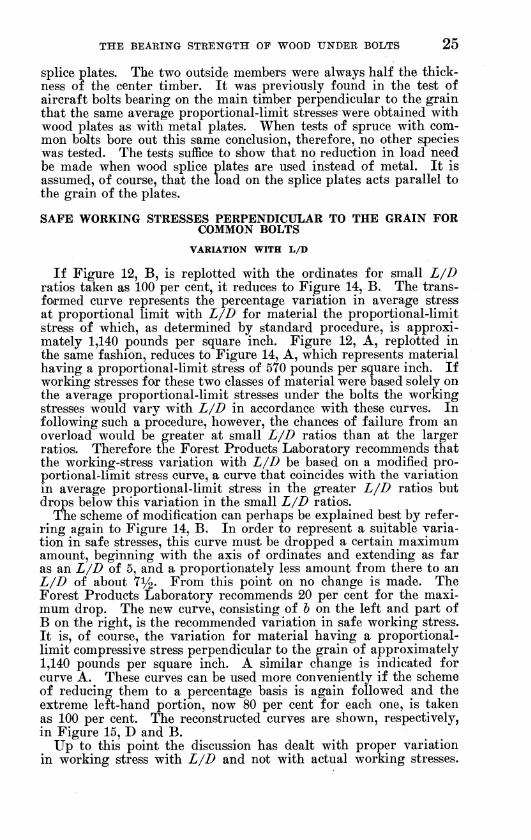
If Figure 12, B, is replotted with the ordinates for small L/I) ratios taken as 100 per cent, it reduces to Figure 14, B. The trans- formed curve represents the percentage variation in average stress at proportional limit with L/D for material the proportional-limit stress of which, as determined h^ standard procedure, is approxi- mately 1,140 pounds per square inch. Figure 12, A, replotted in the same fashion, reduces to Figure 14, A, which represents material having a proportional-limit stress of 570 pounds per square inch. If working stresses for these two classes of material were based solely on the average proportional-limit stresses under the bolts the working stresses would vary with L/D in accordance with these curves. In following such a procedure, however, the chances of failure from an overload would be greater at small L/D ratios than at the larger ratios. Therefore the Forest Products Laboratory recommends that the working-stress variation with L/D be based on a modified pro- portional-limit stress curve, a curve that coincides with the variation in average proportional-limit stress in the greater L/D ratios but drops below this variation in the small L/D ratios.
The scheme of modification can perhaps be explained best by refer- ring again to Figure 14, B. In order to represent a suitable varia- tion in safe stresses, this curve must be dropped a certain maximum amount, beginning with the axis of ordinates and extending as far as an L/D of 5, and a proportionately less amount from there to an L/D of about 7%. From this point on no change is made. The Forest Products Laboratory recommends 20 per cent for the maxi- mum drop. The new curve, consisting of 6 on the left and part of B on the right, is the recommended variation in safe working stress. It is, of course, the variation for material having a proportional- limit compressive stress perpendicular to the grain of approximately 1,140 pounds per square inch. A similar change is indicated for curve A. These curves can be used more conveniently if the scheme of reducing them to a percentage basis is again followed and the extreme left-hand portion, now 80 per cent for each one, is taken as 100 per cent. The reconstructed curves are shown, respectively, in Figure 15, D and B.
Up to this point the discussion has dealt with proper variation in working stress with L/D and not with actual working stresses.

26 TECHNICAL BULLETIN 3 3 2^ U. S. DEPT. OF AGRICULTURE
The basic stresses that are to be modified to obtain actual working stresses will be presented later.
Since there is a considerable range in the strength properties of our common woods, no single curve of variation in stress, for the reasons already given, is suitable for all. In setting up curves to apply to the various groups of species listed in Table 2, it is neces- sary to know the proportional-limit stress for each group. The approach to basic bolt-bearing stresses perpendicular to the grain will disclose what these proportional-limit stresses are. Before at- tempting to set up the stress variation applicable to each group, therefore, it will be convenient to set up the basic stresses.
Í3 90
■ 60
^40
^30
^¿0 5
N \ \
\ \
\ \
\ X X V
\ ^\
\ ^.
"^ ^s
.^
♦
^ /?/)T/0
FIGURE 14.—Variation in average bolt-bearing stress perpendicular to the grain with the ratio of the length of the bearing (L) in the main member to the diameter of the bolt (D) : A, For material having a proportional-limit stress of 570 pounds per square inch ; a, recommended modification of curve A for actual use ; B, for material having a proportional-limit stress of 1,140 pounds per square inch ; &, recommended modification of curve B for actual use
DETERMINATION OF BASIC STRESSES
The general scheme of developing basic bolt-bearing stresses per- pendicular to the grain from general strength data published by the Forest Products Laboratory was to modify the average proportional- limit stress perpendicular to the grain of small, clear, green speci- mens as indicated in the following steps:
(1) Multiplication by 1.20 to correct for an increase in strength with seasoning. The actual increase is more than 20 per cent, but

THE BEABING STRENGTH OF WOOD UNDER BOLTS 27
checking, which usually accompanies seasoning, tends to partly off- set the increase in strength.
(2) Division by 2.25 to cover variability and factor of safety. Minor departures from this simple scheme were necessary in set-
ting up stresses for species that show a decided tendency to split easily or that exhibit abnormal tendencies in drying.
The scheme summarized in the preceding paragraphs may ap- pear to provide no reduction for the effect of long-time loading. The lactors, however, are applied to a proportional-limit stress, and not to a maximum stress as was done in arriving at basic stresses parallel
\ ̂ ̂ v..
N >
^ \
^ .^A— N 1 Nv
^w^ ^^^ ^wc
^
N V
0 1 Z 3 4 5 6 7 d 9 /O II 12 iS
FIGURE 15.—The percentages recommended for use \^ith basic stresses perpendicular to the grain in calculating safe working stresses for woods of Table 2 : A, For group 1 conifers and hardwoods ; B, for group 2 conifers ; C, for group 2 hard- woods and group 3 conifers ; D, for group 3 hardwoods
to the grain. This proportional-limit stress may safely be taken as the long-time maximum.
The basic stresses calculated in accordance with the general pro- cedure outlined in the preceding are given in the last column of Table 2.
As stated in connection with the basic stresses parallel to the grain, the stresses of Table 2 need not be reduced for grade. They apply only to seasoned timbers used in a dry, inside location. This limita- tion intends that the timbers be seasoned prior to installation. Modifications necessary when the conditions of service are more severe are explained in the footnote to the table.
28 TECHNICAL BULLETIN 3 3 2^ U. S. DEPT. OF AGRICULTURE
MODIFICATION OF EXPERIMENTALLY DETERMINED CURVES FOR CLA.SS OF MATERIAL
The proportional-limit stresses perpendicular to the grain of green specimens for the groups of wood listed in Table 2 were as follows :
Pounds per square inch
Group 1, conifers and hardwoods 300 Group 2, conifers _ 375 Group 2, hardwoods, and group 3, conifers 510 Group 3, hardwoods _ 750
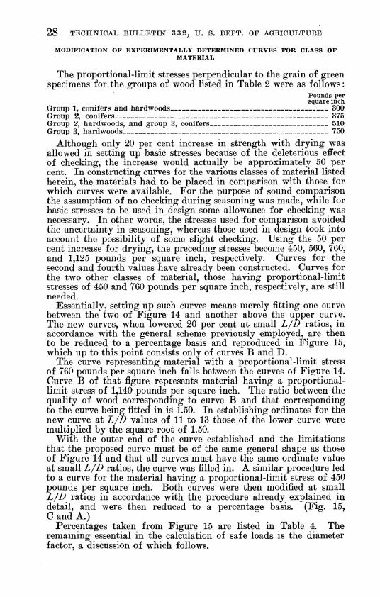
Although only 20 per cent increase in strength with drying was allowed in setting up basic stresses because of the deleterious effect of checking, the increase would actually be approximatel;;^ 50 per cent. In constructing curves for the various classes of material listed herein, the materials had to be placed in comparison with those for which curves were available. For the purpose of sound comparison the assumption of no checking during seasoning was made, while for basic stresses to be used in design some allowance for checking was necessary. In other words, the stresses used for comparison avoided the uncertainty in seasoning, whereas those used in design took into account the possibility of some slight checking. Using the 50 per cent increase for drying, the preceding stresses become 450, 560, 760, and 1,125 pounds per square inch, respectively. Curves for the second and fourth values have already been constructed. Curves for the two other classes of material, those having proportional-limit stresses of 450 and 760 pounds per square inch, respectively, are still needed.
Essentially, setting up such curves means merely fitting one curve between the two of Figure 14 and another above the upper curve. The new curves, when lowered 20 per cent at small L/D ratios, in accordance with the general scheme previously employed, are then to be reduced to a percentage basis and reproduced in Figure 15, which up to this point consists only of curves B and D.
The curve representing material with a proportional-limit stress of 760 pounds per square inch falls between the curves of Figure 14. Curve B of that figure represents material having a proportional- limit stress of 1,140 pounds per square inch. The ratio between the quality of wood corresponding to curve B and that corresponding to the curve being fitted in is 1.50. In establishing ordinates for the new curve at L/D values of 11 to 13 those of the lower curve were multiplied by the square root of 1.50.
With the outer end of the curve established and the limitations that the proposed curve must be of the same general shape as those of Figure 14 and that all curves must have the same ordmate value at small L/D ratios, the curve was filled in. A similar procedure led to a curve for the material having a proportional-limit stress of 450 pounds per square inch. Both curves were then modified at small L/D ratios in accordance with the procedure already explained in detail, and were then reduced to a percentage basis. (Fig. 15, CandA.)
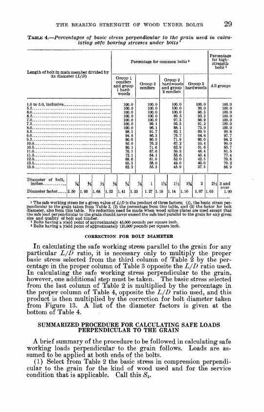
Percentages taken from Figure 15 are listed in Table 4. The remaining essential in the calculation of safe loads is the diameter factor, a discussion of which follows.
THE BEARING STRENGTH OP WOOD TINDER BOLTS 29
TABLE 4.—Percentages of 'basic stress perpenêîoular to the grain used in calcu- lating safe hearing stresses under bolts ^
Length of bolt in main member divided by-
Percentage for common bolts « Percentage
for high- strength
bolts 3
its diameter (LJD) Group 1 conifers
and group 1 hard- woods
Group 2 conifers
Group 2 hardwoods and group 3 conifers
Groups hardwoods All groups
1.0 to Ö.0, inclusive _ 100.0 100.0 100.0 100.0 100.0 100.0 100.0 98.1 94.6 90.0 86.0 80.1 76.1 72.1 68.6 65.3 62.2
100.0 100.0 100.0 100.0 100.0 99.1 96.1 91.7 86.3 80.9 76.2 71.6 67.6 64.1 61.0 68.0 66.3
100.0 100.0 100.0 99.6 97.3 93.3 88.1 82.1 76.7 71.9 67.2 62.9 59.3 65.6 62.0 49.0 46.9
100.0 99.0 96.3 92.3 86.9 81.2 75.0 69.9 64.6 60.0 66.4 61.6 48.4 46.4 42.5 40.0 37.6
100.0 6.5 100.0 6.0 - 100.0 6.6 100.0 7.0 100.0 7.6. - 100.0 8.0 - 100.0 8.6 - . - . - 99.8 9.0 97.7 9.5 . - _ 94.2 10.0 - 90.0 10.6 86.7 11.0 81.6 11.5 77.4 12.0- 73.6 12.6 70.2 13.0 _ _ 66.9
Diameter of bolt, inches
2.60 1.96 1.68
8^
1.41
U 1
1.27
11^ IK2
1.14
18^ 2 23^
1.07 1.03
3 and
Diameter factor 1.6 2 1.3 ̂ 1. 19 1. 10 over
1.00
1 The safe working stress for a given value of L/D is the product of three factors; (1), the basic stress per- pendicular to the grain taken from Table 2, (2) the percentage from this table, and (3) the factor for bolt diameter, also from this table. No reduction need be made when wood splice plates are used except that the safe load perpendicular to the grain should never exceed the safe load parallel to the grain for any given size and quality of bolt and timber.
2 Bolts having a yield point of approximately 46,000 pounds per square inch. 3 Bolts having a yield point of approximately 126,000 pounds per square inch.
CORRECTION FOR BOLT DIAMETER
In calculating the safe working stress parallel to the grain for any particular L/D ratio, it is necessary only to multiply the proper basic stress selected from the third column of Table 2 by the per- centage in the proper column of Table 3 opposite the L/D ratio used. In calculating the safe working stress perpendicular to the grain, however, one additional step must be taken. The basic stress selected from the last column of Table 2 is multiplied by the percentage in the proper column of Table 4, opposite the L/D ratio used, and this product is then multiplied bv the correction for bolt diameter taken from Figure 13. A list of the diameter factors is given at the bottom of Table 4.
SUMMARIZED PROCEDURE FOR CALCULATING SAFE LOADS PERPENDICULAR TO THE GRAIN
A brief summary of the procedure to be followed in calculating safe working loads perpendicular to the grain follows. Loads are as- sumed to be applied at both ends of the bolts.
(1) Select from Table 2 the basic stress in compression perpendi- cular to the grain for the kind of wood used and for the service condition that is applicable. Call this Si.

30 TECHNICAL BULLETIN 3 3 2, U. S. DEPT. OF AGRICULTURE
(2) Calculate the LJD ratio for the part of the bolt in the main member and for this ratio select the proper stress percentage from Table 4. Call this percentage r.
(3) Select the diameter factor from Figure 13 or from Table 4. Call this factor v.
(4) Multiply the basic stress S-^ by the percentage T and by the diameter factor v. The result, JS^XTXV^SZ^ is the safe working stress for the particular L/D ratio used.
(5) Multiply this stress by the projected area of the bolt and the result is the safe working load, whether metal or wood splice plates are used.
EXAMPLE
Calculate the safe load on a joint such as that of Figure 1, B, 5, if the wood is seasoned coast type Douglas fir, the condition of service dry, inside location, the thickness of the center member 4 inches, and the connecting common bolts four in number and five-eighths inch in diameter.
The basic stress from Table 2 is 275 pounds per square inch. The diameter-of-bolt factor from Table 4 is 1.52. The L/D ratio is 4-^0.625 or 6.4 and the corresponding stress percentage from Table 4 is 99.6.
The safe stress is then
275X1.52X0.996=416 pounds per square inch.
The safe load for four bolts is
4 X 416 X 4 X 0.625=4,160 pounds.
SAFE WORKING STRESSES PERPENDICULAR TO THE GRAIN FOR BOLTS OF HIGH STRENGTH
It has already been stated herein that the yield-point strength of the common bolts tested was approximately 45,000 pounds per square inch, and that bolts with a higher yield point will sustain higher loads parallel to the grain than common bolts. The same is true for bearing perpendicular to the grain. The previous study of aircraft bolts already mentioned indicates what the safe bearing stress may be for bolts having a yield point of approximately 125,000 pounds per square inch.
By following the same procedure that yielded the percentages given in the left-hand portion of Table 4 for common bolts, corre- sponding percentages were obtained from the aircraft bolt data. For L/D ratios of 9 and larger the percentages calculated thus were found to yield working stresses for bolts of small diameter that were greater, in certain instances, than those parallel to the grain for the same bolt. Although the proportional-limit stress under a small bolt bearing perpendicular to the grain in a species with a relatively high across-the-grain strength may, under certain conditions, be some- what higher than the proportional-limit stress parallel to the grain, it seems inadvisable to use higher working loads across the grain than parallel to the grain. The percentages calculated from the aircraft- bolt data were Sieref ore modified in such a way that, when used with the properties listed in Table 2, the calculated safe loads perpendicu-
THE BEARING STRENGTH OF WOOD UNDER BOLTS " 31
lar to the grain would not be greater than those parallel to the grain for joints made with metal splice plates.
Tne adjusted percentages for bolts having a yield point of ap- proximately 125,000 pounds per square inch are listed in the last column of Table 4. They apply to all groups of species listed in Table 2.
The earlier pages of this bulletin have pointed out that, when wood splice plates are used in place of steel, the safe loads parallel to the grain must be reduced 20 per cent, whereas no such reduction need be made for loads acting perpendicular to the grain. Consequently, under the conditions in which the safe load perpendicular to the grain on a joint with metal splice plates is about equal to the safe load parallel to the grain on the same kind of joint, the designer may think that the unreduced perpendicular load could be greater than the reduced parallel load if wood splice plates were used. Under these conditions, however, the limiting factor would be the capacity of the splice plates for load. In this report the assumption is made that, under all conditions, the bearing thrust in wood plates is par- allel to the fibers. Because of the direction of the thrust in the splice plates, the safe load applied perpendicular to the grain of the main timber through wood splice plates can not exceed the safe load applied parallel to the grain of the main timber through similar plates. A footnote covering this limitation appears in Table 4.
BOLT-BEARING STRENGTH OF WOOD AT ANY ANGLE WITH THE GRAIN
FORMULA FOR CALCULATION
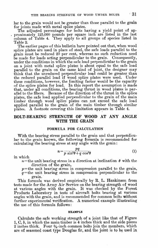
With the bearing stress parallel to the grain and that perpendicu- lar to the grain known, the following formula is recommended for calculating the bearing stress at any angle with the grain :
^ VQ. /.s ^~í>sin2(9 + 2C0s2|9 ^^^
in which 72.=the unit bearing stress in a direction at inclination 0 with the
direction of the grain, ^=the unit bearing stress in compression parallel to the grain, ç'^the unit bearing stress in compression perpendicular to the
grain. This formula was derived empirically by R.. L. Hankinson from
tests made for the Army Air Service on the bearing strength of wood at various angles with the grain. It was checked by the Forest Products Laboratory in tests of aircraft bolts bearing at various angles with the grain, and is recommended for common Jbolts vrithout further experimental verification. A numerical example illustrating the use of this formula follows :
EXAMPLE
Calculate the safe working strength of a joint like that of Figure 1, C, &, in which the main timber is 4 inches thick and the side pieces 2 inches thick. Four %-inch common bolts join the members, which are of seasoned coast type Douglas fir, and the joint is tç bç u§çd m

32 ■ TBCHITICAL BULLETIN 3 3 2^ U. S. DEPT. OF AGRICULTURE
a dry, inside location. The smaller angle between the side pieces and center piece is 30°.
The basic stresses shown in Table 2 are 1,300 pounds per square inch parallel to the grain and 275 pounds per square inch perpen- dicular to the grain. The L/D ratio is 4-^ 0.625=6.4. For this ratio the stress percentage for parallel bearing from Table 3 is 63.0. A factor of 0.80 must be applied in calculating the stress parallel to the grain because wood side pieces are used. Therefore
^=1,300X0.63X0.80=655 pounds per square inch.
For an L/B ratio of 6.4 the stress percentage from Table 4 for bearing perpendicular to the grain is 99.6. The diameter of bolt factor is 1.52. No correction need be made for the fact that load is applied through wood side plates. Therefore
i=275X 1.52X0.996=416 pounds per square inch.
The sine of 30° is 0.50 and the cosine 0.866. Therefore
655X416 ^^^ , . , ^^(655X0.25) +(416X0.75r^^^ P^™^^ P^^ '^^^^^ ^^^^-
The safe load for four bolts is
4X572X4X0.625=5,720 pounds.
DETAILS OF DESIGN
The tests already described and discussed were confined to the symmetrical 2-end loading of single bolts in joints of various types. They supply a fundamental basis for arriving at calculated safe loads that act in any direction with respect to the fibers in bolted timbers. In addition to this work the Forest Products Laboratory has conducted tests to obtain information about certain specific de- tails of design, such as the proper placement of the bolts in a joint. A discussion of a number of these important details is given in the following pages.
1-END LOADING COMPARED WITH 2.END LOADING
Tests have shown that a load applied to only one end of a bolt, perpendicular to its axis, may safely be taken as half the symmetrical 2-end load for the same value of LJD. Further, if the 1-end load acts at an angle with the axis of the bolt, the component at 90 degrees with that axis may be made equal to half the 2-end load. This state- ment assumes, of course, that ample bearing area under the washers or plates is provided to resist the load component parallel to the axis of the bolt.
COMBINED ACTION OF SEVERAL BOLTS IN A JOINT
Tests of joints having a number of bolts of the same diameter showed that the applied load was equally distributed among the several bolts, provided the bolt holes were carefully centered.

THE BEAEIKG STRENGTH OF WOOD UNDER BOLTS 33
Although no tests were made on joints in which common bolts of different diameters were used, a limited number of such tests were made with aircraft bolts. It was found that, when the ratio of the diameters was not greater than two to one, no appreciable error was introduced by assuming that the bolts shared the applied load in proportion to their individual capacities to sustain load. Consider- ing the combined safe load of several bolts equal to the sum of their individual safe loads is therefore good practice, provided the margin and the spacing are sufficient to develop the full strength of each one.
CHOICE OF BOLT DIAMETER
Although the diameter of the bolts in a joint is determined, in a general way, by the thickness of the timbers to be connected, in any given instance a wide latitude in the choice is allowable. On the other hand, however, two important elements, efficiency and safety, indicate definitely the best part of the L/D range.
Efficiency, as defined in the appendix, means the proportional- limit load on a bolt divided by the weight of metal in the main mem- ber. As shown in this appendix, for bearing parallel to the grain the efficiency of common bolts increases with L/D until a ratio of 6 is reached, and then remains constant. For bearing perpendicu- lar to the grain, the increase continues to a ratio of about 7, and then drops off slightly. The L/D ratios for high-strength bolts at maxi- mum efficiency, however, are even greater than the values for common bolts.
The element of safety has already been discussed in connection with working stresses, where it was stated that the margin of safety was greater at large L/D ratios than at small ones.
From the standpoint of both efficiency and safety, therefore, a bolt diameter that will give an L/D ratio of 6 or more is desirable. Ratios somewhat less than 6, however, entail only minor loss in joint efficiency with perhaps some saving in labor.
PLACEMENT OF BOLTS IN A JOINT
LOADS PARALLEL TO THE GRAIN
ALIGNMENT
The term '' a row of bolts " is convenient in describing the proper alignment of bolts in a joint. In this bulletin the term means a number of bolts placed in a line that is parallel to the direction of the applied load. Thus in Figure 1, A, the bolts in both a and & would be described as placed in two parallel rows.
In making joints such as those shown in Figure 1, A, it is preferable to place the bolts in the various rows opposite one another and not to stagger them. If staggering is used in order to permit an odd number of bolts on each side of a splice, special precaution must be taken to provide sufficient area at the critical section, as described in later paragraphs.
SPACING
The center-to-center spacing of the bolts in a row, for loads acting parallel to the grain, should be at least four times the bolt diameter. Because the shear stress in the wood is not uniform across the thick-

34 TECHNICAL BULLETIN âââ, XT. S. DËPT. OF ÁGUlCULTtJBE
ness of the bolted timber, concentrating at the edges, the spacing should actually increase somewhat with the L/D ratio if the maxi- mum capacity of the joint is to be developed. With the constant spacing of four times the bolt diameter, however, the maximum loads for L/D ratios greater than 6 will not be much below the maximum obtainable with the most favorable spacing. Further, the loads at failure will be much greater than 2.25 times the safe loads, which relationship applies in the small L/D range with optimum spacing.
The spacing between adjacent bolt rows is controlled by the reduc- tion in area at the critical section. The critical sections of the main members in the joint shown in Figure 1, A, a^ occur at the two bolts at the left and the two at the right. The net tension area remaining at the critical section, when coniferous woods are used, should be at least 80 per cent of the total area in bearing under all the bolts in the particular timber in question. When hardwoods are used, the net tension area at the critical section should be at least equal to the bearing area under all the bolts. Although it may appear to do so, the difference in requirements does not mean that a relatively higher tensile stress is allowed for conifers than for hard- woods. The bolt-bearing stresses of the conifers, as a group, were found to be relatively lower than those for the hardwoods. A 20 per cent correction was made for this difference in arriving at basic stresses. The preceding rule for conifers operates to prevent a like differential in the allowable tensile stress.
To illustrate the use of the rule applying to hardwoods, consider two oak timbers 3 inches thick by 4 inches wide joined end to end in a tension splice by means of plates and i^-ii^^h bolts. With four bolts placed in two parallel rows on each side of the butt joint, the area in bearing under the bolts is 6 square inches. At the critical section there are two bolt holes, and the net area in tension is therefore 9 square inches, which is more than ample. If six bolts are similarly used in two parallel rows, the bearing area is 9 square inches, but the net area in tension at the critical section remains 9 square inches, which is again ample. If eight bolts were used in two parallel rows, the joint would be expected, under its maximum load, to fail in tension at the critical section.
If an odd number of bolts of a selected diameter are required in each half of a joint in which an even number of parallel rows are employed, desirable practice will alter the diameter of all or part of the bolts in such a way as to obtain an even number. This will avoid staggering. If staggering is resorted to, however, special pre- cautions must be taken in determining the tension area required at the critical section. The procedure can best be explained by refer- ring to Figure 1, A, a. If a seventh bolt were required in each half of the joint, usual practice would place it in the center of the timber at a longitudinal distance from the present end bolts equal to the longitudinal spacing between the other bolts. In calculating the required area at the critical section, however, the seventh bolt should be considered as placed between the last pair of bolts. This rule, of course, would be unreasonable if the odd bolt were spaced an abnor- mally great distance from the last pair.
The reason for requiring an assumed placement of the odd bolt between the end bolts can best be explained by referring again to

THE BEARING STRENGTH OF WOOD UNDER BOLTS 35
Figure 1, A, a. With a tensile load applied to the joint shown, the lines of tension between the bolt rows proceed uninterrupted through the main members. On the contrary, an extra bolt placed beyond the end bolts and staggered between the bolt rows interrupts these lines of tension. This requires part of the tensile stress between the boJt rows to be transmitted to the net section at the single bolt by shear. The wood under the bolts is already greatly stressed in shear and the added shear stress occasioned by the shifting of the tensile stress can not be sustained. The result is failure at a load about the same as that obtained when the odd bolt is placed between the last two.
MABGIN
By end margin is meant the distance from the end of a bolted timber to the center of the bolt hole nearest the end. By edge margin is meant the distance from the edge of the timber to the center of the nearest bolt hole.
The end margin in joints under tension acting parallel to the grain should be at least seven times the bolt diameter when coniferous woods are used and at least five times the bolt diameter when hard- woods are used. When the joint is under a compressive load the end margin may be made the same as the bolt spacing, which is four times the bolt diameter for both conifers and hardwoods.
The end margin should actually increase with L/D for the same reasons given in the discussion of spacing, but the use of a constant margin is also justified by the same reasoning that permits a constant spacing.
The edge margin for loads acting parallel to the grain should be the same whether the joint is in tension or in compression. For L/D ratios of about 5 or 6, this margin should be at least one and one-half times the bolt diameter. For ratios greater than 6, in- creased safety will be obtained by a margin slightly more than one and one-half times the bolt diameter. For ratios less than 5 it may be slightly less. Usual practice requires the edge margin to be half the distance between bolt rows. In most instances the area require- ments at the critical section will be such that an edge margin equal to half the distance between rows will be more than sufficient to meet the preceding minimum requirements.
LOADS PERPENDICULAR TO THE GRAIN
ALIGNMENT
When load is applied perpendicular to the grain of the main mem- ber of a joint through metal splice plates, it is not necessary that the bolts in the various rows be opposite one another. In fact, it is preferable to stagger them in order to avoid splitting.
In a joint like Figure 1, B, &, in which two wood members are at right angles with a main timber, it is necessary to align correspond- ing bolts when the design load approaches the bolt-bearing capacity of the side timbers. If the design load for the main timber is much less than the bolt-bearing capacity of the side timbers, as it would be for large bolts of common steel, staggering may be employed.
36 TECHNICAL. BULLETIN 3 3 2^ U. S* DEPT. OF AGRICULTURE
SPACING
The minimum center-to-center spacing of bolts in the across-the- grain direction for loads applied perpendicular to the grain through metal splice plates need only be sufficient to permit the tightening of the nuts. For wood splice plates on a joint like Figure 1, B, 6, the spacing is controlled by the rules applying to loads acting parallel to the grain if the design load approaches the bolt-bearing capacity of the side timbers. When the design load is less than the bolt-bearing capacity of the side timbers, the spacing may be reduced below that required to develop their maximum capacity.
The spacing required between adjacent bolt rows depends upon the L/D ratio. The only tests made to determine this spacing were con- fined to the placement in which the bolts in adjacent rows were op- posite one another. With such placement the distance between rows should be at least two and one-half times the bolt diameter for an LJD ratio of 2, and five times the bolt diameter for L/D ratios of 6 or more. For ratios between 2 and 5 the spacing between rows may be obtained by direct interpolation. The fact that the spacing in ques- tion increases so rapidly with L/B immediately suggests the desira- bility of staggering to avoid splitting with loads perpendicular to the grain.
MAEGIN
For loads acting perpendicular to the grain, the margin between the edge toward which the bolt pressure is acting and the bolt or bolts nearest this edge should be at least four times the bolt di- ameter. The margin at the opposite edge is relatively unimportant.
LOADS AT AN ANGLE WITH THE GRAIN
It is virtually impossible to set up general rules regarding the alignment, spacing, and margin of bolts to cover all possible direc- tions of the applied load. Uniform stress in the main members and a uniform distribution of load to all the bolts, however, require that the gravity axis of the members shall pass through the center of resistance of the bolt groups. Beyond that the designer must rely upon a sense of proportion and fitness rather than upon exact cal- culation in applying the rules already set forth to a condition of loading that is between the limits discussed.
CENTERING AND BORING THE BOLT HOLES
In the tests upon which this report is made the holes in the splice plates were placed accurately. The holes in the main members were centered with those in the plates. All holes were bored or drilled perpendicular to the surfaces involved. The discussion in this bul- letin is based upon such workmanship. Obviously the workmanship is important, especially with a group of bolts, because of the small- ness of the distortions that normally accompany the loads involved. Although careful centering is important for all L/D ratios, it is especially important when small ratios are used.
The bolt holes should be of such diameter that the bolts can be driven easily. When the thickness of timbers is great this require- ment may mean the boring of holes appreciably oversize. This,

THE BEAKIISTG STRENGTH OF WOOD UNDER BOLTS 37
however, is preferable to forcible driving, which puts initial stress in the wood, thereby lowering both the proportional-limit and the maximum loads. The use of freely clearing bits with side cutter lips will insure freedom from initial splits, which, of course, are detrimental.
CROSS BOLTS
When the load on a bolted joint acts parallel to the grain a wedge of crushed fibers usually forms under the bolts after the propor- tional limit has been passed. This wedge produces a cleavage action that, combined with the stress components acting perpendicular to the grain, tends to split the bolted timbers. Such splitting does not start soon enough to have any appreciable effect upon the pro- portional-limit load, but it often helps to determine the maximum load. Stated in another way, the first real evidence of splitting is usually associated with the maximum loads and not with loads near the proportional limit.
When load is applied perpendicular to the grain, splitting again seems to start too late to affect the proportional-limit load, but it does have a veir definite effect upon the maximum load.
Seasoning after assembly may also start splitting at the bolts, and once started a split develops readily when load is applied.
For these reasons the use of cross bolts is recommended, especially when the L/D ratio is small, because under such conditions the safe load is closer to the maximum load than it is in the large LJD range, as previously pointed out.
Tests in which cross bolts were employed were insuflS.cient to fur- nish rules for the size and the number required for particular joints. Cross bolts, however, can certainly be smaller than the main bolts and often only one or two are required. When a single cross bolt is used in each half of a tension joint subjected to a load acting parallel to the grain, it should be placed in the portion described earlier in this bulletin as the end margin. Preferably it should be placed close to the bolt or bolts nearest the end of the timber and it well may actually touch these bolts.
CONDITION OF LUMBER
Wood shrinks as it seasons. Across the grain the change in dimen- sion is of considerable magnitude, although along the grain it is usually negligible. Because of the shrinkage across the grain, com- plications commonly arise from the use of green material in a bolted joint. In a joint like Figure 1, A, &, the effect of shrinkage is mini- mized. On the other hand, if relatively wide members are joined end to end with metal splice plates, as in Figure 1, A, a^ splits are likely to develop at or near the bolts when shrinkage takes place. The same results are likely to occur if two or more members are bolted together in such a way that the grain of one piece is at right angles to that in the other pieces, as illustrated in Figure 1, B, &. If splits do develop, the loads are lowered in consequence.
To illustrate what actually happens and to obtain some measure of the reduction in load caused by such splitting, a series of tests was made. Joints of green material were assembled and then al- lowed to air season for a time. The joints were of the type illus-

38 TECHNICAL BULLETIN 3 3 2^ U. S. DEPT. OF AGBICULTUKE
trated by Figure 1, B, &, and the L/D ratios ranged from 4 to 12. The proportional-limit loads ranged from 25 to 40 per cent of what would normally be expected of the material at the time of test. The maximum loads were approximately half of what would be expected had the material been allowed to season before assembly.
For these reasons the recommended use of the stresses as listed in Table 2, or as modified for condition of service, is based on the assumption that the timbers when assembled will be approximately at the moisture condition to which they will ultimately come in use.
APPENDIX
METHOD OF FITTING STRESS CURVES TO THE DATA
The points on Figure 16, A, are the proportional-limit bolt-bearing stresses parallel to the grain, for the conifers tested, when expressed as percentages of the maximum crushing strength of the control specimens. This curve, which is a reproduction of Figure 5, B, shows graphically how these data vary with the ratio of the bearing length (L) of the bolt in the main member to the bolt diameter (D).
In placing curve A of Figure 16 it was first assumed that, at an L/D ratio of 2, very little if any bending of the bolt has taken place when the proportional-
¡^ 55
^ -25
¿ P
( N a
\ o
\ 0
\
A tO""^ r
^/ ^ \
0
/ N /
o \
o
o
/ o N^ o
£s^
/ o ■^
o o
/ /
/
/ o t 2 3 4 5 6 7 0 9 10 II 12 13
FIGURE 16.—The relationship between average proportional-limit bolt-bearing stress parallel to the grain and L/B ratio, and between proportional-limit load and length of bearing in main member for a given diameter of bolt : A, Average proportional- limit stress ; B, load for a constant diameter
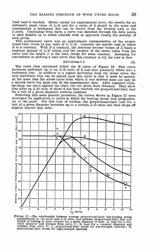
THE BEABISTG STRENGTH OP WOOD UNDER BOLTS 39 limit load is reached. Hence, except for experimental error, the results for an extremely small value of L/B and for a value of 2 should be the same and consequently a horizontal line can be drawn from the vertical axis to the 2 point. Continuing from there, a curve was sketched through the data points in such fashion as to either coincide with or approach closely the average of each group.
This preliminary curve was an approximate representation of the propor- tional-limit stress at any ratio of Lt to D. Consider the specific case in which D is a constant. With B a constant, the abscissas become values of B times a constant instead of L/B ratios, and the product of the stress taken from the curve and the length L is the load, except for some constant. Assuming for convenience in plotting a load curve that this constant is 0.2, the load is then
0.2X stress Xi. (2) The loads thus calculated follow the B curve of Figure 16. This curve
increases uniformly up to an L/B ratio of 2 and then gradually fillets into a horizontal line. In addition to a logical derivation from the stress curve, the only restriction that can be placed upon this curve is that it must be smooth. At the same time the stress curve from which it was derived must not only be a smooth curve but must also fit the experimental data. After repeated trials, checking one curve against the other, the two given were obtained. They show that after an L/B ratio of about 6 has been reached, the proportional-limit load for a bolt of a given, diameter remains constant.
Following this same general procedure, the curves shown in Figure 17 were developed for application to joints in which the bearing thrust was perpendicu- lar to the grain. For this type of loading, the proportionaMimit load for a bolt of a given diameter increases up to a certain L/B ratio and then drops off slightly beyond that ratio.
^ ^d- — ̂ ^
o / o / ^
Tv— -2^
^ 140
°n"^ [^
/ \ \
X ^-> ̂ ^
I
s
I 1 60
Á f
K S \J "^ ̂
/ Ö ^
^
> \
/ 8^ S^ \
^
J / S k '—.
'"^«^
1 h 40 /
^^ o
/ f
0 / 6 7 /3
FIGURE 17.—The relationship between average proportional-limit bolt-bearing stress perpendicular to the grain and h/B ratio, and between proportional-limit load and length of bearing in main member for a given diameter of bolt : A, load for a con- stant diameter and stresses from curve C; B, load for a constant diameter and stresses from curve D; C, proportional-limit stress for low-strength material; D, proportional-limit stress for high-strength material

40 TECHNICAL BULLETIN 3 3 2, U. S. DEPT. OF AGRICULTUEE
An interesting and useful relationship between efficiency and L/D ratio can be developed by assuming L to be a constant instead of D. By efficiency is meant the load divided by the weight of metal in the main member; that is, in the length Z. With L constant, the load becomes stress multiplied by bolt diameter and multiplied again by some constant. The efficiency is the load divided by the product of some constant and the square of the bolt diameter. Written algebraically,
Efficieiicy=^f^=^ = ír.¿A, (3) in which
Äp=the proportional-limit stress, i> = the diameter of the bolt, Z=the length of the bolt in the main member, ¿"i, Ä'2, Ä's, and Ä'4=constants.
If K4, is taken as 0.2 for convenience, the efficiency is again erpressed by equation (2).
It is obvious that values calculated by this formula and plotted against h/D would fall upon the load curves already shown in Figures 16 and 17.
The load curve of Figure 16, now presented as an efficiency curve, shows that with the length (L) fixed the efficiency increases up to an L/B of 6 and then remains constant. The corresponding curves of Figure 17, however, show that for bearing perpendicular to the grain efficiency on the basis assumed increases up to a certain L/D and then diminishes slightly.
1). S. GOVERNMENT PRINTING OFFICE: 1932
For sale by the Superintendent of Documents, Washington, D, C. Price 5 cents


![[TECHNICAL DATA]STRENGTH OF BOLTS, SCREW PLUGS, AND](https://img.pdfslide.net/doc/110x75/5868da921a28abc92d8b8855/technical-datastrength-of-bolts-screw-plugs-and-.jpg)