Embed Size (px)
Citation preview
1
The Behaviour of Steel Fibre Reinforced
Concrete Material and its Effect on Impact
Resistance of Slabs
Ahmad Bazgir
Submitted for the Degree of Master of Philosophy in Structural Engineering
City University London
School of Mathematics, Computer Science & Engineering
May 2016

THE FOLLOWING PARTS OF THIS THESIS HAVE BEEN REDACTED FOR COPYRIGHT REASONS: p. 13: Image from Bekaert Dramix. p. 17: Image from Bekaert Dramix. p. 18: Image of effect of aggregate size on fibre distribution. p. 25: Image of stress lines in concrete under tension. p. 30: Graph of air blast pressure response over time. p. 34: Image of experimental results. p. 39: Image of test set up for impact testing machine.

2
Ahmad Bazgir MPhil in Structural Engineering
City University London
School of Mathematics, Computer Science &
Engineering
Department of Civil Engineering
Supervisor: Dr Feng Fu

3
Table of Contents
ABSTRACT ............................................................................................................... 10
CHAPTER ONE ........................................................................................................ 11
Introduction ................................................................................................................ 11
1.1. Aim .............................................................................................................. 14
CHAPTER TWO ....................................................................................................... 16
Literature Review ....................................................................................................... 16
2.1. Steel fibre reinforced concrete and effect of fibre reinforcement ............... 16
2.2. Mechanical properties of SFRC .................................................................. 20
2.2.1. Compressive strength ....................................................................... 20
2.2.2. Flexural strength ............................................................................... 20
2.2.3. Ductility ............................................................................................ 21
2.2.4. Fracture toughness ............................................................................ 22
2.3. Advantages and Disadvantages of Steel Fibres in Concrete ....................... 23
2.4. Crack control ............................................................................................... 24
2.5. Load deflection behaviour of SFRC ground slabs ...................................... 26
2.6. Failure of SFRC ground slabs ..................................................................... 28
2.7. Behaviour of materials under blast load ...................................................... 29
2.8. Blast loading ................................................................................................ 31
2.9. Steel fibre reinforced concrete slab under impact loading .......................... 33
2.10. Numerical literature ..................................................................................... 43
2.10.1. Cracking models for concrete ........................................................... 47
2.11. Conclusion ................................................................................................... 47
CHAPTER THREE .................................................................................................... 49
Methodology .............................................................................................................. 49
CHAPTER FOUR ...................................................................................................... 50
Experimental Work .................................................................................................... 50

4
4.1. Material and mix design .............................................................................. 50
4.2. Concrete mix design .................................................................................... 50
4.3. Mixing procedure ........................................................................................ 52
4.4. Test set up .................................................................................................... 57
4.4.1. Cube Compression Test .................................................................... 57
4.4.2. Cylinder Compression Test .............................................................. 65
4.4.3. Cube VS cylinder Compressive Strength ......................................... 71
4.4.4. Split Tensile Test .............................................................................. 71
4.4.5. Flexural Beam Test .......................................................................... 78
4.4.6. Relation between split tensile strength and flexural strength ........... 88
CHAPTER FIVE ........................................................................................................ 90
Conclusion and Recommendation.............................................................................. 90
REFERENCES ........................................................................................................... 92

5
Table of Figures
Figure 1. Shapes of steel fibres (Bekaert Dramix) ..................................................... 13
Figure 2. Crack controlling mechanism provided by steel fibres (Bekaert Company)
.................................................................................................................................... 17
Figure 3. Effect of the aggregate size on the fibre distribution (Johnston, 1996) ...... 18
Figure 4. The three important parameters of a steel fibre .......................................... 19
Figure 5. Stress lines in concrete under tension (Tatnall and kuitenbrauer) .............. 25
Figure 6. Comparison between SFRC and plain concrete ground slabs .................... 26
Figure 7. Typical load displacement response of SFRC ground slab (Falkner and
Teutsch, 1993) ............................................................................................................ 29
Figure 8. Air-blast pressure response over time (Hinman, 2003) .............................. 30
Figure 9. Free field blast pressure probe set up arrangement and field blast test set up
.................................................................................................................................... 32
Figure 10. Experimental results (Mahalingam et al. 2010) ........................................ 34
Figure 11. Experimental set-up for impact test (Madheswaran et al. 2014) .............. 35
Figure 12. Experimental set-up for impact test (Hrynyk et al. 2014) ........................ 36
Figure 13. Test set up for one-way slab specimens (Doo Yeol Yoo, 2009) .............. 38
Figure 14. Test set-up for impact testing machine (Elavenil et al. 2003) .................. 39
Figure 15. Cracking Pattern of Plates (Elavenil and Knight, 2012)........................... 40
Figure 16. FE Results: (a) Damage fringe for bottom of slab (b) deformed shape
(Mokhatar and Abdullah, 2012) ................................................................................. 45
Figure 17. Concrete Constituents ............................................................................... 51
Figure 18. (a) Addition of coarse aggregate (b) Addition of sand, (c) Dry constituents
mixed uniformly, (d) Water added to the mixture ..................................................... 52
Figure 19. Adding steel fiber to the mix .................................................................... 52
Figure 20. Forms of slump ......................................................................................... 53
Figure 21. Measuring slump ...................................................................................... 53
Figure 22. Slump measurement after mixing ............................................................. 54
Figure 23. Covering inside the moulds with specific oil ........................................... 55
Figure 24. (a) sample moulds on shaking table, (b) Concrete moulds ....................... 56
Figure 25. Covering of the specimen after casting with wet cloth............................. 56
Figure 26. Concrete specimens cured in water tank .................................................. 57
Figure 27. Cube compression test set up .................................................................... 58

6
Figure 28. Cube Compression Test Results – 21 Day ............................................... 59
Figure 29. Cube Compression Specimen Results (21 Day) ....................................... 60
Figure 30. Cube Compression Specimen Results (21 Day)-continued ...................... 61
Figure 31. Cube Compression Test Results – 21 Day ............................................... 63
Figure 32. Cube Compression Specimen Results (28 Day) ....................................... 63
Figure 33. Cube Compression Specimen Results (28 Day)-continued ...................... 64
Figure 34. Cylindrical Compression Test Set up. ...................................................... 65
Figure 35. Cylinder Compression Results ................................................................. 67
Figure 36. Plain concrete sample after the test .......................................................... 68
Figure 37. SFRC0.5 sample after the test .................................................................. 68
Figure 38. SFRC1.0% samples after the cylinder compression test .......................... 69
Figure 39. SFRC1.0% samples after the cylinder compression test .......................... 70
Figure 40. SFRC1.0% samples after the cylinder compression test .......................... 70
Figure 41. Split tensile test set-up .............................................................................. 73
Figure 42. Split Tensile Strength Comparison ........................................................... 73
Figure 43. PC Samples after Split Tensile Test ......................................................... 75
Figure 44. SFRC0.5 Samples after Split Tensile Test ............................................... 76
Figure 45. SFRC1.0% samples after split tensile test ................................................ 76
Figure 46. SFRC1.5% samples after split tensile test ................................................ 77
Figure 47. SFRC2.0% Samples after split tensile test ............................................... 77
Figure 48. Arrangement of loading of test specimen (BS EN 12390-5:2000)........... 78
Figure 49. Flexural Beam Test Set Up ....................................................................... 78
Figure 50. Flexural Beam Test Results ...................................................................... 80
Figure 51. Flexural Beam Test Results (Early stages) ............................................... 82
Figure 52. PC beam test results .................................................................................. 83
Figure 53. SFRC1.0 Beam Test Results..................................................................... 84
Figure 54. SFRC1.0 Beam Test Results..................................................................... 85
Figure 55. SFRC1.5 Beam Test Results..................................................................... 86
Figure 56. SFRC2.0 Beam Test Results..................................................................... 87
Figure 57. Steel fibers bridging the concrete beam crack under flexure ................... 88

7
List of Tables
Table 1. Properties of fibres used in (Ong et al. 1999) .............................................. 41
Table 2. Steel fiber properties .................................................................................... 50
Table 3. Mix proportions of the concrete mixtures for 1m3 ...................................... 51
Table 4. Cube Test Results ........................................................................................ 59
Table 5. Cube Compression Test Results for 28 Days .............................................. 62
Table 6. Cylinder Compression Test Results ............................................................. 66
Table 7. Cube vs cylinder compressive strength ........................................................ 71
Table 8. Cylinder Split Tensile Test Results .............................................................. 74
Table 9. Flexural Test Results .................................................................................... 79
Table 10. Relation between split tensile strength and flexural strength .................... 88

8
ACKNOWLEDGMENT
I would like to acknowledge the instructions and support from my
research supervisor Dr Feng Fu from School of Mathematics, Computer Science &
Engineering, Department of Civil Engineering , City University London, during my
M-Phil study. This study has made me to the person I am at present, not only in
relation to my professional career but also with respect to my individual
development.
Last, but not least, I would like to thank my family especially my parents and friends
for the encouragements and general understanding of my absence, physically as well
as mentally, every now and then during my studies. Without your continuous support
it would have been impossible for me to finish my studies.

9
I certify that this project is wholly my own work and that all material extracted from
other sources is clearly referenced.
I grant powers of discretion to the City University Librarian to allow this thesis to be
copied in whole or in part without further reference to me. This permission covers
only single copies made for study purposes, subject to normal conditions of
acknowledgement.

10
ABSTRACT
Concrete structures are usually subjected to both static as a long term and dynamic as
a short term loads. The impact resistance of plain concrete is low and that’s mainly
due to a fairly low energy dissipating features and inadequate tensile strength. To
compensate for the weak tensile properties of the concrete the reinforced concrete is
used and it has a better potential as a practicable structural material for such
application under extreme loads such as impact. However, concrete is a developing
material and the relevant studies towards the change and development of concrete
which researchers have carried out to date reveals that the developed concrete
improves the behaviour of structural member more when compared to conventional
concrete. Fibre Reinforced Concrete (FRC) material is a developed concrete that has
been proposed to improve the tensile behaviour of the concrete using fibres in the
concrete mix. Steel Fibre Reinforced Concrete (SFRC) is popular FRC material that
is being studied to improve the structural behaviour of members under different load
conditions.
This study aims to investigate and examine the structural behaviour of steel fibre
reinforced concrete material at different volume fraction of the fibers. Experimental
work is conducted for this research to obtain results on the behaviour of SFRC. The
experimental work consists of testing concrete under tension, compression and
flexure.

11
CHAPTER ONE
Introduction
Plain concrete slabs are known to have low strength and low strain capacity, however
these structural properties could be improved by addition of fibres, allowing the
thickness of the layer to be reduced. There are different fibres that are used in the
concrete namely glass fibre, steel fibre, synthetic fibres and natural fibres. The
improvement in the material behaviour of the fibre reinforced concrete depends on
dosage and characteristics of the used fibres.
The main important effect of fibres as reinforcement is to influence and control the
tensile cracking of concrete. Yet, the fibre reinforced concrete is known to have
considerable impact on the slab cost owing to reduced thickness needs, prolonged
useful life and reduction in maintenance costs.
Amongst the fibres mentioned, steel fibres are the most researched and more
practical. Steel fibre reinforced concrete is a type of concrete that contains randomly
oriented discrete steel fibres. The main aim of addition of steel fibres to concrete is to
control crack widening and crack propagation after the concrete matrix has cracked.
By control of the cracking the mechanical properties of the composite material as a
result will be improved significantly.
Addition of randomly distributed steel fibres improves concrete properties, such as
static flexural strength, ductility and flexural toughness. SFRC has been largely used
in airport pavements due to the extreme and damaging loads acting on the pavement.
(Johnston, 1982) Some other examples of the structural and non-structural
applications of SFRC are hydraulic structures, airport and highway paving and
overlays, industrial floors, refractory concrete, bridge decks, concrete linings and
coverings, and thin-shell structures. The elasticity modulus of steel fibres is as high
as 210 MPa providing very high tensile strength with minimal deformation. The
large number of fibres used for concrete members enables a uniform distribution of
fibres through the compound, thereby creating a composite material possessing
homogeneous mechanical behaviour. They provide a cohesive mix, creating a three-
dimensional reinforced net system (Tokgoz, 2012). The important characteristic in
FRC material is the bond between the fibers and the matrix. Fibres are designed in

12
different geometries to increase the bond and interfacial friction between aggregates
and cement paste. Fibre texture such as the end-hooked fibres improve the bond
between the fibres within the matrix, thus increasing the necessary force required to
pull out the fibre from the concrete. The forces induced in a SFRC when subjected to
load are redistributed within the concrete, which restrains the formation and
extension of cracks. The result is a more ductile reinforced concrete which is able to
maintain a residual capacity in the post-cracking phase (Tokgoz, 2012). Thus
resulting in an increased load-carrying capacity, improved shear and bending
strength of concrete, superior flexural ductility, toughness, and fatigue endurance. In
addition, SFRC has higher life cycle and the maintenance requirements are reduced
resulting in lower costs. (Elsaigh, 2001) Another advantage of the SFRC is that at an
adequate volume fraction they can replace conventional steel reinforcement when
designed properly and it reduces the construction time since the steel fibres are
added directly as one of the concrete mix constituents, hence no steel fixing or
adjustment is required. (Association of Concrete Industrial Flooring Contractors,
1999)
The research on the SFRC members and slabs under static loads showed that they
can provide equivalent performance compared to conventionally reinforced concrete
slabs when equivalent amounts of reinforcement is used. (Bischoff et al., 2003)
Researchers during recent years have stated that steel fibres significantly improve the
impact resistance of concrete material (Nataraja, 2005) making it a suitable material
for structures subjected to impact loads. Overall, the above factors suggest that SFRC
is potentially the most beneficial type of material from engineering and economical
prospective to be considered for structural slabs subjected to high loads. The aim of
this study is explained below.
Steel fibre reinforced concrete (SFRC) is a composite material similar to normal
concrete but with fibres as part of mixture constituent. It is made of cement, fine
aggregate, coarse aggregate and other components or admixtures that can commonly
be used in concrete with dispersion of discrete small steel fibres. It has been used in
concrete since the early seventies and for different applications like slab on ground,
pavements, and bridge decks. Fibres have different geometries also they vary in

13
dimensions. The length of fibres could vary from 25mm to 75mm and the diameter
from 0.5mm to 1.3mm. Different fibre shapes are illustrated in Figure 1.
The addition of fibres to concrete has shown improvement in concrete flexural
strength, toughness, ductility, impact resistance, fatigue strength and resistance to
cracking. In addition the deformation at peak stress is much greater than plain
mortar. Fibres help to alter the behaviour of concrete after the initiation of cracking.
The crack bridging behaviour of fibres is what improves the ductility of matrix.
The main advantageous property of SFRC is its superior resistance to cracking and
crack propagation. The fibres are able to hold the matrix together even after
extensive cracking due to its bridging effect. SFRC has the ability to arrest cracks;
therefore fibre composites retain increased extensibility and tensile strength, both at
first crack and at ultimate stress. The net result this is the fibre composite will have a
marked post-cracking behaviour and ductility which is unremarked in ordinary
concrete in which the tension post crack is negligible. The material is therefore
transformed from a brittle to a ductile type of material which would increase
substantially the energy absorption characteristics of the fibre composite and its
ability to withstand repeating applied load such as shock or impact loads.
Figure 1. Shapes of steel fibres (Bekaert Dramix)

14
Steel fibres are generally made of carbon steel or stainless steel, where the latter is
used for structures that require corrosion-resistant fibres. Tensile strengths may be in
the range 200- 2600 MPa and ultimate elongations between 0.5% and 5%. Although
a tensile strength is significantly higher than that of the matrix is needed, very strong
fibres may have an adverse effect on the reinforcing efficiency; pull-out experiments
have shown that in low-strength matrices high tensile strength steel fibres cause more
severe matrix spalling around the fibre exit point.
1.1. Aim
Additional strengthening method is required to improve the resistance of concrete
structures under the extreme loads. The aim of this study is to expand upon the
findings of the previous researchers and investigate the strengthening effect of fibers
on concrete and find out the mechanical behaviour of steel fibre reinforced concrete
as a material with specific end hooked steel fiber.
The main objectives of this study are:
Review previous research on FRC material and structural behaviour of
structural members.
Review previous experimental research on the impact behaviour of slabs and
use of fibers.
Review the numerical studies conducted by previous researchers to analyse
the impact behaviour of slabs.
To evaluate the effect of end hooked steel fibers on concrete mechanical
behaviour consisting compressive strength, split tensile strength, flexural
strength, and ductility.
To examine the effect of fiber volume fraction on SFRC material
performance.
To make a comparison for the performance of concrete with and without steel
fibre reinforcement on the material levels both graphically and qualitatively.
Overall, this thesis aims to firstly outline the previous research that has been
conducted on steel fiber reinforced concrete material and impact behaviour of
structural slabs and plates that have been studied so far. In Chapter three the
methodology used for conducting this research is explained. Then the experimental

15
work on materials consisting of plain concrete and SFRC is thoroughly explained
and results are presented in Chapter four. At the end of this thesis a conclusion based
on the experimental results has been drawn and further work for future projects has
been recommended.

16
CHAPTER TWO
Literature Review
This Chapter summarises the work that has been conducted to date by other
researchers on the steel fiber reinforced concrete and its structural performance
focusing on the impact load.
2.1. Steel fibre reinforced concrete and effect of fibre reinforcement
There are several types of steel fibres that have been used in the past. Apart from
other mix constituents, there are four important features of steel fibre that are found
to have an effect on the properties of the composite, namely: type (i.e. shape),
volume fraction, aspect ratio (the ratio of length to the diameter of the steel fibre) and
orientation of fibres in the matrix. Recently, optimisation of these parameters have
been studied to improve the fibre matrix bond characteristics and to enhance fibre
dispensability (Soroushian and Bayasi, 1991). It was found that SFRC containing
hooked end stainless steel wires has superior physical properties compared to straight
fibres. This was attributed to the improved anchorage provided and higher effective
aspect ratio than that of the equivalent length of the straight fibre (Ramakrishnan,
1985)
Laboratory scale tests conducted by many agencies and researchers indicate that the
addition of steel fibres to concrete significantly increase the total energy absorbed
prior to complete separation of the specimen (Johnston, 1985). The presence of steel
fibres was also found to improve fatigue properties, flexural strength, shear strength
and impact strength (Johnston and Zemp, 1991, Morgan and Mowat, 1984). The
improvement of mechanical properties of SFRC is attributed to the crack controlling
mechanism. Bekaert Company suggested that there are two mechanisms that play a
role in reducing the intensity of stress in the vicinity of crack. These mechanisms are:
1. The higher load resistance of steel fibres near the crack tip due to their higher
young’s modulus compare to the surrounding concrete. (Figure 2.a)
2. Steel fibres bridge the crack and transmit some of the load across the crack.
(Figure 2.b)

17
The ability of steel fibres to resist crack propagation is primarily dependant on the
bond between the concrete and fibres as well as fibre distribution (i.e. spacing and
orientation). The bond between the concrete and fibres is the mechanism whereby the
stress is transferred from the concrete matrix to the steel fibres.
Steel fibre reinforced concrete (SFRC) appears stiffer (lower slump) compared with
conventional concrete without fibres even when the workability (judged by any test
using vibration) is the same (Johnston, 2001). Steel fibers tend to interlock together.
Vibration is encouraged to increase the density, to decrease the air void content and
to improve the bond with reinforcement bars. In spite of a stiff appearance, a well-
adjusted fibre mixture can be pumped (ACI 544, 1993). “The size of the fibres
relative to that of the aggregates determines their distribution (Figure 3). It is
recommended to choose fibres not shorter than the maximum aggregate size to be
effective in the hardened state. Usually, the fibre length is 2-4 times that of the
maximum aggregate size.” (Johnston, 1996 and Coetze, 1990) It is recommended to
reduce the volume of coarse aggregates by 10% compared with plain concrete to
facilitate pumping. The initial slump of plain concrete should be 50-75 mm more
(b) Steel fibres across the crack transmit
some transmit some tension
(a) Steel fibres at the tip of
crack resist the crack
growth
Figure 2. Crack controlling mechanism provided by steel fibres (Bekaert Company)

18
than the desired final slump; to obtain the desirable workability, super plasticiser
should be added to the mixture rather than excess water (Johnston, 2001).
Figure 3. Effect of the aggregate size on the fibre distribution (Johnston, 1996)
The size, the shape and the content of the coarse aggregates as well as the geometry
and the volume fraction of steel fibres affect the workability of concrete. At a given
fibre diameter and volume fraction, compact ability is linearly related with the aspect
ratio (lf/df) of the fibres. The relative fibre to coarse aggregate volume and the
‘balling up’ phenomenon govern the maximum possible content of steel fibres.
The performance of different types of steel fibres can be characterised by the
following three parameters (Figure 4):
The aspect ratio (L/D)
The tensile strength
The bond between fibres and the matrix (dependant on fibre type)

19
Steel fibres, compared to traditional fabric reinforcement, have a tensile strength
typically 2-3 times greater and a significant greater surface area to develop bond with
the concrete matrix (ACIFC, 1999). These parameters will affect the performance of
steel fibre in concrete as well as the interaction between fibres and concrete matrix.
For example, a steel fibre with high tensile strength which has bad bond in concrete
most likely will not perform as the steel tensile strength could permit. The
combination of these three parameters will give a toughness value at a certain
dosage. However, for different dosages (volume fraction of fibres in concrete), the
toughness value for a specific steel fibre will vary. (See section 2.2.4)
Figure 4. The three important parameters of a steel fibre
Steel fibre concrete is mainly used for industrial floors and pavements applications.
“In the United Kingdom, more than 2 million m3 of steel fibre reinforced slabs have
been installed over the past ten years” (ACIFC, 1999). The stresses induced on a
concrete slab are complex depending on the load that is applied to the member. In
addition, there are number of stresses which are difficult to measure, arising from a
number of causes such as shrinkage and thermal effects, sharp turns from fork lift
trucks, and impact loads (Knapton, 2003).
Regarding the economical aspect, the main energy component of concrete slabs is the
energy used for manufacturing cement and steel reinforcement. Although current
material and energy prices already indicate that concrete slabs can be more cost-
effective but the energy efficiency and further reduction in the total structural
element dimensions could be obtained in the production of concrete slabs.

20
2.2. Mechanical properties of SFRC
Fibres are known to enhance the mechanical performance of concrete with regard to
its tensile and shear strength, toughness, ductility, durability, fatigue and shrinkage
resistance (Gopalaratnam, 1991). Following are an overview of these characteristics.
2.2.1. Compressive strength
The effect of steel fibres on the concrete compressive strength is much debated in
literature. It has been found by many researchers (e.g. Winterberg, 1998) that the
inclusion of steel fibre in concrete increases its compressive strength value. This
increase ranges between marginal and significant increases in compressive strength.
The effect of fibres on the compressive strength is attributed to two stabilising
actions according to Grübl et al. (2001). First, a larger amount of pores in the
concrete admixture, which decreases the compressive strength and second factor,
would be the fibre bridging effect across the micro cracks, which results in an
increased compressive strength. The concrete compressive strength of the material
depends on the magnitude of these effects and it may change. The effect of steel
fibres on the compressive strength therefore depends on the concrete mixture, the
kind and amount of steel fibres and the manufacturing process. Despite the increase
in the compressive strength of the concrete, it is unclear whether the addition of steel
fibres influences the rotation capacity of plastic hinges. It is generally agreed that
steel fibres enhance the ductility of concrete in compression (Grübl et al., 2001).
Steel fibres as well as stirrup reinforcement increase the confining capacity of
concrete. This is reflected in the stress-strain relationship of concrete with a more
ductile post-peak behaviour. For steel fibres, the orientation of the fibres needs to be
perpendicular to the compressive loading in order to be effective. It is therefore
expected that the addition of steel fibres increases the rotation capacity of plastic
hinges in case of concrete failure as a result of the increase of concrete ductility in
compression.
2.2.2. Flexural strength
The low flexural strength of plain concrete could be overcome and improved by the
addition of steel fibres. A review of the literature on SFRC indicates that in general
the addition of short, randomly-oriented steel fibres increase the flexural strength of
plain concrete by about 1.5 to 3.0 times, taking into account the type and content of

21
the steel fibres. Roesler (2003) used different type of fibres and analysed the flexural
resistance of beams and large scale slabs on ground and concluded that discrete
fibres contribute to the flexural strength of concrete slabs beyond what is predicted
by beam tests. The slabs flexural strength was 1.8 to 2.2 times greater than the beam
flexural strength for the fibre reinforced concrete and 1.4 times greater for the plain
concrete. The flexural cracking load of fibre reinforced concrete slab was 25 to 55
percent higher than the plain concrete slab. The addition of synthetic fibres increased
the “flexural cracking load relative to plain concrete slabs by 30 percent. The
crimped steel fibres at 39 kg/m3 showed the greatest increase to the flexural strength
(55 %) which was attributed to its higher concrete flexural strength” with the
inclusion of steel fibres.
2.2.3. Ductility
FRC is known to provide higher ductility than ordinary concrete. Ductility is the
ability of concrete to undergo maximum plastic deformation before collapse. It is
considered a good warning indicator before failure. Mahalingam et al. (2013) studies
the ductility behaviour of steel fibre on concrete beams. They used steel fibre content
of 0.5, 1 and 1.5 % by volume. They concluded that the ultimate load carrying
capacity of concrete beams were improved by 14, 20 and 32%, respectively,
compared to conventional reinforced concrete beam. Ductility could also be
increased using synthetic fibres (Roesler, et al., 2006, Sounthararajan and Sivakumar,
2013).
However, ductility in concrete beams could only be achieved with higher dosage of
fibre added at approximately 5% but the effect of fibres on early-age shrinkage is not
well established at this amount. Considering that only low-dosage amount of fibre
are needed, ductility would have very little effect on early-age shrinkage.
The Modulus of Rupture (MOR) beam tests conducted by Tadepalli et al. (2010)
revealed that “the non-fibrous beams had no ductility. In these beams, once the
maximum tensile stress was reached, the beams failed suddenly without any
warning.” However for the SFRC, “after the onset of initial crack at the beam
bottom, the specimen did not fail suddenly, but it demonstrated considerable residual
strength.”

22
2.2.4. Fracture toughness
Fracture toughness measures the energy absorption capacity of material under static
or dynamic load. Fracture toughness is used to evaluate the post-cracking behaviour
for concrete at the deflection at mid span. Specimen toughness is a measure of the
energy absorption capacity of the test specimen and it is related to ductility. In SFRC
the amount and type of fibres in the concrete influence this property of the material
in different ways.
By adding steel fibre in concrete its post-crack behaviour or toughness of SFRC is
improved, which is considered as one of the main effect of fibres in concrete matrix.
This effect is useful regarding design of hyper static construction such as slab on
ground. When the first crack appears, the fibres in concrete start to act and have the
ability to absorb and redistribute the loads, hence redistribute the energy, so that the
SFRC will still be able to bear loads even after the formation of cracks. In fact,
SFRC has a ductile behaviour or toughness and therefore, that excess of flexural
capacity from the plastic phase (i.e. post-crack behaviour) can be used for design of
structure when deformation is essential and must be controlled such as in the design
of slabs or for structures where deformations is important in the design such as
underground linings. The higher fracture toughness is the reason for higher load
capacity of SFRC slab on ground when compared to a conventional concrete slab
with the same thickness.
Balaguru et al. (1992) studied the effect of fibre length and stated that the length of
the fibre did not have significant effect on the toughness for steel fibres with hooked
ends.
Tadepalli et al. (2010) studied the effect of different steel fibres at two 0.5% and
1.5% volume fraction of steel fibre and it was concluded that plain concrete did not
demonstrate any toughness since it didn’t have any residual strength. The mix with
short fibres at the dosage of 1.5% had the greatest toughness value.
Overall, both steel and synthetic fibres improve the concrete fracture toughness. The
improvement depends on the dosage amount but in most cases the fracture toughness
increases with increasing dosage rate.
23
Many literature reports on how toughness is affected by the fibre type, dosage, fibre
material properties, and bonding conditions are available in more details in ACI 544
report and elsewhere. (Roesler et al., 2006, Sravana et al., 2010 and Richardson et
al., 2010)
Yazici et al. (2013) studied the mechanical properties of steel fibre reinforced
concrete with 0.5%, 1.0% and 1.5% volume fraction of fibres. The aim of the
research was to identify the mechanical losses in terms of the SFRC’s compressive
strengths and splitting tensile strengths following the effect of the impact. 50 kg mass
was freely dropped onto the specimens in order to produce a certain amount of
energy. The impact tests were repeated up to the failure and crushing of the
specimen. The best performance under compressive strength was obtained for SFRC
with l/d=65, while SFRC with l/d=80 showed the best performance under splitting
tensile strength. Long fibres had more positive effect on the compressive strength of
the material. The volume fraction of 1.5% showed the best performance under
impact load compared to other SFRCs. Overall, it was concluded that the steel fibres
increased the impact fracture energy of the steel fibre concrete (SFRCs) by 3–23
times compared to plain concrete.
2.3. Advantages and Disadvantages of Steel Fibres in Concrete
The advantage of using steel fibre can be summarized as follow:
Produce more ductile concrete with a smaller number of cracking
Reduction of the influence of shrinkage cracking
High tensile strength
High compressive strength
Higher economically efficient compared to conventional steel solutions and
enhance costs with lesser fibre amount
Reducing schedule time due to fast installation
Reduce the permeability in concrete, which ensures protection of concrete
due to the negative effects of moisture
Easy material handling
High durability
Can replace wire mesh in most elevated slabs.

24
Disadvantage:
There are problems involved in attaining uniform distribution of fibres and
dependable concrete properties
At aggressive exposure condition the corrosion of the surface could take
place, influencing the look of the surface
The use of SFRC requires more accurate configuration as opposed to normal
concrete
Reduced workability
Though, as the amount of fibres is increased, the workability of the concrete is
influenced. Therefore, special techniques and concrete mixtures are used for steel
fibres such as addition of super plasticizer. Finishing problem may arise if proper
techniques and proportions are not used, with the fibres coming out of the concrete.
2.4. Crack control
Steel fibres effectively limit the extension of micro-cracks which are always present
in concrete (see Figure 5). In concrete without fibres, tension cannot be transmitted
across the crack, that is, once the tensile capacity of the plain concrete is exceeded,
the micro-crack will extend rapidly resulting in brittle failure. The action of the steel
fibres in a concrete slab is to reduce the concentration of stresses near the micro-
cracks by:
Fibres bridging the crack and therefore transmitting some of the load across
the crack
Fibres near the crack tip resisting more loads owing to their higher modulus
of elasticity compared to that of the surrounding concrete.

25
The fibre anchorage will effect on the ductile behaviour. If the anchor is too uneven
then the fibre will fail in a brittle manor. The anchorage must have the following
concepts:
Allow the fibre to progress to its full potential i.e. reach maximum stress
start to slip earlier than the fibre breakage to avoid brittle failure
Absorb energy as the fibre is being pulled out
In the case of floor slabs, a crack is formed where the ultimate stress in the floor is
exceeded locally. Steel fibres cause the crack to behave as a hinge, resulting in a
redistribution of stresses. Unlike a broken zone in a brittle material, this hinge can
still resist stresses depending on the type and dosage used and thus increases the load
bearing capacity of the member.
Figure 5. Stress lines in concrete under tension (Tatnall and kuitenbrauer)

26
2.5. Load deflection behaviour of SFRC ground slabs
Extensive research has been carried out to investigate the effect of the steel fibres on
the load capacity of ground slabs (Kaushik et al. 1989, Beckett, 1990, Falkner and
Teutsch, 1993, Elsaigh, 2001, Bischoff et al. 2003, Chen, 2004). In these studies, full
scale slab tests were conducted to compare the behaviour of centrally loaded SFRC
slabs to plain concrete or welded wire fabric reinforced concrete slabs. It was shown
that by adding steel fibres to the concrete mix the load carrying capacity of the
ground slabs will increase significantly. Figure 6.a and Figure 6.b show the load
displacement (P-Δ) responses from two investigations conducted by Chen (2004) and
Falkner and Tuetch (1993) respectively. It is prominent that SFRC containing
hooked-end steel fibres yields greater load carrying capacity compared to both plain
concrete and SFRC containing mill-cut fibres (straight fibres having a relatively low
tensile strength). Figure 6 shows that the addition of 30 kg/𝑚3 of hooked-end steel
fibres resulted in greater load carrying capacity for the SFRC ground slab compared
to addition of 20 kg/𝑚3 of similar steel fibres type.
(a) Chen (2004) (b) Falkner and Teutch (1993)
Figure 6. Comparison between SFRC and plain concrete ground slabs

27
Several explanations for the increased carrying capacity of SFRC ground slab have
been suggested. As well as the structural ductility of the statically indeterminate slab,
it has been recognised that the post cracking strength of steel fibre reinforced
concrete is the reason behind the increased load carrying capacity of SFRC ground
slabs ( Kearsley and Elsaigh, 2003).
The result from the static tests on the full-scale ground slabs indicated that an
appreciable thickness reduction, depending on steel content, is possible for SFRC
ground slabs when compared to counterpart plain concrete slabs. Indeed it was found
that about 16% thickness reduction is possible when 15kg/𝑚3 of hooked-end steel
fibres were used (Elsaigh, 2001).
Bischoff et al. (2003) stated that the thickness reduction is justified by the following
arguments:
1. The post cracking strength of the SFRC allows for redistribution of stresses
leading to an increased load carrying capacity and therefore the slab thickness
can be reduced.
2. Steel fibres significantly increase the flexural capacity and therefore the slab
thickness can be reduced.
3. Steel fibres will improve the fatigue resistance of the concrete and can lead to
thinner slabs as the allowable stress is increased.
SFRC is deemed to be a superior material for concrete roads due to its improved
mechanical properties compared to plain concrete. Although support provided by the
subgrade means that bending stress in slabs is generally low, the flexural capacity of
the slab remains an important aspect to be considered. This is especially crucial when
bending stresses increase significantly due to unnoticed subgrade erosion, as is
common in the case when the subgrade subside at the pavement corner or edge. In
conventional reinforced concrete slabs, the steel reinforcement is placed between the
mid to two third depth of the slab to mainly resist stresses induced by changes in the
environmental conditions (Paramasivam et al. 1994). The load carrying capacity of
concrete slab can be enhanced by placing the reinforcement in the bottom of the slab.
Thus, allowing the concrete in the bottom surface to crack and the reinforcement
there to withstand the positive moment. Top reinforcement can also be provided
especially at corners and edges to resist negative moment.

28
Fibre reinforced concrete has many applications due to its increased strength and
ductility. However, this type of concrete is not widely used due to ongoing research
on its long term properties. FRC can be used in beams to take advantage of the
higher ductility and tensile strength of this material for better crack control and
material cost saving. Structural elements can be produced with fibres completely
replacing conventional reinforcement. Generally, the Main use of fibre reinforcement
has been in applications such as highways, pavements, runways, tunnels, deck slabs
and wall panels in buildings.
2.6. Failure of SFRC ground slabs
Fibre reinforced concrete can be used to make slabs for nearly any applications
including precast slabs, parking garages, slabs surface repairs and industrial floor
slabs. Significant advantage is realised when conventional reinforcement is
completely replaced by the fibres as a result reducing cost, time and other logistical
problems. Slab thickness can be reduced, which saves material while still retaining or
even increasing flexural strength.
The behaviour of a centrally loaded SFRC slab is relatively linear up to initial
cracking at the bottom face of the slab where they have higher tensile stresses. After
cracking the response then differs slightly from linearity and the slab remains to
carry load till the cracks have extended to the edges and form a failure mechanism.
Substantial indentation occurs in the load introduction zone, while the corners of the
slab are lifted up. The entire loss of load carrying capacity occurs by punching shear
(Bischoff, 2003). Based on the cracking progress, Falkner and Teutsch (1993)
introduced three different behavioural regions. Referring to Figure 7, these three
regions are:
(a) Region I: represents the initial un-cracked behaviour of the slab.
(b) Region II: is governed by the formation of small radial cracks in the central
area where the load is applied.

29
(c) Region III: represents the behaviour when the crack spread in the slab until
collapse.
Figure 7. Typical load displacement response of SFRC ground slab (Falkner and
Teutsch, 1993)
Considerable energy is required for the crack to propagate to the surface and extend
to the edges. It is therefore necessary to consider the post-cracking behaviour when
designing SFRC ground slabs. Failure of ground slabs is normally based on
serviceability issues, which will affect the slab behaviour before cracking occurs and
the slab does not meet the serviceability conditions when it cracks, though in service
ground slabs normally crack without total disruption of service. Coetze and Van der
walt (1990) stated that structural failure occurs when a slab is cracked and the crack
has developed through the full depth along the sides of the slab.
2.7. Behaviour of materials under blast load
Over the past decade, the private sector has been developing standards for blast
resistance design, using the military’s parameters for guidance. Through testing done
by the U.S. Army Corps of Engineers and private associations, engineers and
researchers have studied the behaviour of blasts so that structural members can be
adequately designed for blast events. Since blast loading is an extreme loading event,
reasonable assumptions (such as large deformations and strategic failures) are
required to maintain an economical design (Agnew, et al, 2007). Reinforced concrete
is a kind of material that can meet the demands of blast resistant design because of its
large mass and flexibility in detailing (Galinat, 2007).

30
Blast is a rapid release of energy taking the form of sound, shock-wave, heat and
light. “The shock wave contains of extremely compressed air that wave reproduces
off the ground surface to produce a hemispherical propagation of the wave that
travels outward from the source at supersonic velocities” (Hinman, 2003). The
shockwave of a blast can reflect off a surface with an amplification factor up to 13,
compared to an acoustical wave, which able to reflect with an amplification factor up
to 2. The amplification factor is influenced by the distance the shockwave travels
before reflection and by the angle of incidence.
Another consideration in designing structural members for blast resistant design is
load reversals. Late into the shockwave’s phase, the pressure becomes negative,
creating a suction force. A graph of this response is shown below in Figure 8, where
the blue dotted line indicates initial wave pressures and the red solid line indicates
reflected wave pressures. Clearly, the reflected pressures are stronger than the initial
pressures, as mentioned previously. Immediately following the suction force,
surfaces experience a drag pressure as air rushes in bringing flying debris. “In an
exterior explosion, a small part of the energy is also informed to the ground, making
a crater and generating a ground shock wave parallel to a high-intensity, short-
duration earthquake.” (Hinman, 2003) The extent of damage caused by a blast is
determined by two factors: (1) explosive size measured in pounds of TNT and (2)
distance between explosive and affected structural member.
Figure 8. Air-blast pressure response over time (Hinman, 2003)

31
Reinforced concrete is the most mutual material for blast resistant design, due to its
availability, relatively low cost, mass, and flexibility of detailing. (Laneet al. 2002)
However, to understand the advantages of adding fibre to reinforced concrete,
structural engineers first need to understand the advantages of using conventional
reinforced concrete without fibres.
2.8. Blast loading
Yusof et al. (2010) conducted a research about normal strength steel fibre reinforced
concrete subjected to explosive loading. They have compared the behaviour of
normal strength steel fibre reinforced concrete panels (SFRC) and plain reinforced
concrete subjected to explosive loading.
The experiments were performed by the Blast Research Unit Faculty of Engineering
of the Universiti Pertahanan Nasional Malaysia. They have used 8 reinforced
concrete panels which has the size of 600mm×600mm×100mm. They have used
hooked end steel fibre in this study and the steel fibre reinforced concrete panels
combined three different volume fractions of 0.5%, 1.0%, and 1.5%. The panels were
subjected to explosive loading produced by the explosion of 1kg of explosive charge
situated at a 0.6m standoff distance. The research outcomes showed that by
increasing the amount of steel fibres will affect the blast resistance of a concrete
structure. The best experimental result in this search was achieved by using the
volume of 1.5 % of steel fibre under explosive loading followed by concrete using
1.0% fibres. However the result showed that normal reinforced concrete and concrete
containing fibre volume of 0.5% in the explosive loading are not as effective in
resistance.
Yusof et al. (2010) studied the measurement of filed blast testing data using high
speed data acquisition system for steel fibre reinforced concrete. In this research a
field blast test was showed by the Blast Research Unit of Universiti Pertahanan
Nasional Malaysia to examine the behaviour of steel fibre reinforced concrete panel
subjected to air blast loading. The steel fibre reinforced concrete panels were
subjected to air blast loading using plastic explosive (PE4) weighing 1kg at standoff
distance of 0.3 meter. By using the high speed data acquisition system the factors

32
measured were free field blast pressure, air blast pressure and also acceleration of the
slab.
The concrete test panels used for this study were Steel Fibre Reinforced Concrete
Panel (SFRC) and Normal Reinforced Concrete (NRC) and panels were reinforced
on both compression and tension. The bottom face of the slab was reinforced with 10
mm diameter steel at 200 mm centre to centre distance in both ways. The panels had
a thickness of 150 mm and the dimension was 600× 600 mm. The SFRC mix
combined 1.5 % of hooked-end steel fibres which used mild carbon steel.
They have used high speed data acquisition system which include, blast pressure
probes, pressure sensor, software, cables and software accelerometer which are
attached to the test specimen to measure the parameters. In this investigation high
speed data acquisition system with sampling rate up to 2MHz and eight hardware-
timed digital I/O lines were used to measure the structural reaction towards blast
loading. Furthermore, the sensors are also selected specifically to make sure that they
are capable of responding and delivering signals in the range of microseconds. The
instrumentation and data acquisition system were situated inside a protected concrete
building 40m far from the blast testing place (Figure 9).
The outcome of this study presented the acceleration of the NRC is 7600m/𝑠2 while
SFRC recorded 5100 m/𝑠2. The acceleration rate obtained has a connection with the
failure pattern of the specimen. Acceleration rate signifies the ductility of the test
Figure 9. Free field blast pressure probe set up arrangement and field blast test set up

33
structure. Higher vibration methods can be related with larger shear force and lower
ductility. Hence the acceleration test outcome indication of the low resistance of the
NRC to blast loading.
2.9. Steel fibre reinforced concrete slab under impact loading
The use of FRC in the marine community is based on the properties of impact
resistance and crack control. Impact resistance is needed in jetties, piers and any
place subjected to wear and tear from waves and water borne objects. The main need
for FRC in marine structures is for its ability to control cracks and thereby reducing
the possibility of corrosion in the main steel reinforcement.
Mahalingam et al. (2010) studied SIFCON slab panels under impact loading. RCC,
PCC and FRC slab specimens further more comparison purposes for this study tested
and cast under impact loading. An in-house manufactured impact testing machine
was used in this research to carry out the impact test. The impact test machine has
been fabricated and planned in accordance with the drop weight test, conducted by
dropping an iron ball of diameter 100 mm and weight of 50N from a height of 450
mm.
This study showed fibre acts as an energy-absorption mechanism and by using more
fibre volume in the concrete mix the ultimate impact strength in concrete will
increase. The incidence of the first crack followed by few different cracks and the
fibre bridging across these cracks performed not only as energy absorbing
mechanism, but also as a load transfer mechanism
The maximum energy was absorbed by the SR slabs. At first crack stage,
conventionally reinforced SIFCON slabs with 8%, 10% and 12% fibres had the
energy-absorption capacity 4125%, 8350% and 28066% higher, respectively, when
compared to SIFCON slabs with no conventional reinforcement. The least damage
was attributed to the SR slab with 12% fibre volume in comparison to slabs with
fibre volume of 8% and 10%. In contrast, the PCC slabs were broken into pieces
under impact. (See Figure 10)

34
Figure 10. Experimental results (Mahalingam et al. 2010)
Knight et al. (2012) studied the response of plates under drop weight impact loading,
their results from their investigation on the plates showed that plates that showed
relatively low impact resistance at first cracking, are weak in impact resistance at
failure. The random distribution of steel fibres in concrete resulted in resistance to
expansion and propagation of cracks in the post cracking stage of concrete.
Madheswaran et al. (2014) studied the behaviour of reinforced geopolymer concrete
slab under frequent low velocity impact loading. They have illuminated the
experimental and numerical studies on the performance of reinforced GPC slabs
under repeated impact loading concrete made out of this binder system have a
number of advantages related to conventional Ordinary Portland Cement Concretes
(OPCCs). Significant studies have been done on the impact behaviour of reinforced
concrete structural elements though alike studies have not been stated on GPCs. The
objective of this research was to gain the impact behaviour of reinforced GPC slabs
with ought and with steel fibres and compare with that of OPCC slabs. The general
sizes of the GPC slab were 1 × 1 m, through 60 mm thickness and the test set up
prepared for this experiment is shown in Figure 11. Furthermore Finite element
modelling of slab was carried out by using ANSYS software. The measured impact
load time history is used to excite the structure. The Solid 65 element and link 8
elements were used to model the concrete slab and Reinforcement correspondingly.

35
Displacement boundary conditions are applied at the supports. Transient dynamic
analysis was used to get the terms of deflection time histories. The peak acceleration
of analytical presented a pattern alike to that found from experimental outcomes. The
failure crack pattern of steel fibre reinforced slabs predicted and plain concrete by
finite element analyses are compared with experimental outcomes.
Figure 11. Test set up (Madheswaran et al., 2014)
The highest acceleration and at a specified number of drops, for a given height of
drop was experienced by the OPCC slabs. While GPC slabs had relatively less
acceleration for both panels of plain and fibre reinforced. The acceleration for fibre
reinforced slabs was lower in comparison to the unreinforced panels, which could be
accredited to the larger damping. The GPCC slabs were undergone soft impact due to
the low elastic modulus which was reflected by reduced peak of the load pulse. In
this research it was found that the measured peak acceleration and peak impact load
increases as the height of drop is increased, while the contact duration of pulse
decreases and it depends on the material properties and the stiffness of the slab. The
pattern of the load time variation under repeated impact loading can be represented in
a triangular pattern. Observing the slabs at both the cracking and failure stages
revealed that for GPC panel relatively higher energy was absorbed compared to
OPCC. The failure mode of the plain OPCC and GPC panels was in a perforation
manner. However, scabbing failure was observed for fibre reinforced panels. When
the impact loading is being repeated with low energy a progressive degradation of
stiffness occurs. The FE analysis results on the peak deflection profiles showed a
comparable pattern in agreement with experimental results. It is stated that since the
fibre mixes have less mass participating in vibration, therefore the peak accelerations
Figure 11. Experimental set-up for impact test (Madheswaran et al. 2014)

36
are less. The deflection at mid-span increases as the number of drops increases. Their
research highlighted that by appropriate design, GPC can be used for structural
components subjected to low velocity under repeating impact loading. The
incorporation of steel fibres, improved characteristics such as ductility, toughness,
energy absorption characteristics, bond characteristics and impact resistance.
Hrynyk et al. (2014) studied the behaviour of steel fibre reinforced concrete slabs
under impact load. (Figure 12) In this study seven intermediate-scale slabs were
constructed and tested to failure under sequential drop-weight impacts. The slabs
contained longitudinal reinforcing bars and were constructed with steel fibre contents
ranging from zero (that is, conventional reinforced concrete) to 1.5% by volume of
concrete. The data from the testing program were used to further assess the
performance of steel fibre reinforced concretes in impact-resistant applications and to
provide a well-documented data set pertaining to a research area which is currently
limited within the literature.
Figure 12. Experimental set-up for impact test (Hrynyk et al. 2014)

37
The slabs used were 1800 mm square and 130 mm thick, and were doubly reinforced
with equal amounts of steel in the top and bottom mats of reinforcement. Steel fibres
with end-hooked were used in this study. The FRC slabs exhibited superior
performances under impact loading conditions when compared with no fibrous RC
slabs. The addition of end-hooked steel fibres led to reduce crack spacing’s and
widths; mitigation of local damage mechanisms, such as mass penetration and
concrete scabbing; also increased slab stiffness and capacity. The increased impact
resistances, stiffness’s, and displacement capacities of the R/FRC slabs tended to
correlate with the steel fibre volume fractions provided. The slabs forming the
experimental program were designed such that they would be governed by flexural
failure modes under conventional static loading conditions; however, all but one of
the slabs were controlled by punching shear failures under impact. Inertial force
development, which was shown to result in dynamic loading conditions that differ
from those encountered under static testing, is suggested to be the main contributor
to the punching shear failure modes observed. Under high-mass, low-velocity impact
loading conditions, the behaviours of the slabs were not exclusively governed by
local failure mechanisms. Global deformations contributed to the impact responses of
all slabs, and the influence of local damage development was found to be of less
significance in the R/FRC slabs. As the slabs in this study were ultimately controlled
by punching shear failures under impact, limited benefits were attained as a result of
increasing the longitudinal reinforcement ratios of the RC slabs.
Doo Yeol Yoo (2009) investigated the effect of FRPS strengthening and steel fibres
on the enhancement of impact resistance of concrete slabs. This research investigated
the compressive and flexural behaviours under static loading conditions for normal
strength concrete as well as steel fibre reinforced concrete (SFRC), including 30mm
long end-hooked steel fibres in different volume fractions varying from 0.5-1.5%.
The flexural strengthening effect of externally bonded FRP (Fibre Reinforced
Polymer) sheets and steel fibres on one-way slabs was investigated in a high strain
rate range conditions (i.e. impact tests) using a drop-weight impact testing machine.
For this test prismatic specimens with dimension of 50mm×100mm×350mm were
used. Two different unidirectional FRPs (AFRP and CFRP) were used to strengthen
the longitudinal direction of the specimens. The maximum capacity of 800 Joules
was used for the impact test. Load cell and speedometer were used and attached to

38
the top of the drop weight to measure the impact load and velocity respectively. A
drop weight of 12.965 kg was dropped freely from the height of 1045 mm applying
single impact load to the mid-span of the specimens. The average impact velocity of
4.5 m/s and 133(J) potential energy respectively were used. Figure 13 below shows
the test set up.
Figure 13. Test set up for one-way slab specimens (Doo Yeol Yoo, 2009)
The result of this study showed the compressive strength of concrete was reduced by
the addition of steel fibres; also the flexural resistance of concrete is significantly
improved by using FRP sheets and steel fibres for strengthening. In the case of the
AS and CS specimens, the peak impact loads were about 19% higher than that of the
NS specimen and the maximum deflections of the top of the specimen were
decreased by about 34% due to the strengthening effect of AFRP and CFRP sheets.
About 2.3~2.7 times higher impact energy was dissipated by strengthening with
AFRP and CFRP sheets compared to the NS specimen. The maximum mid-span
deflection and residual deflection of the CS specimen were about 1.3 times higher
than those of the AS specimen. This indicates that AFRP sheet gives improved
impact resistance performance with SFRC than CFRP sheet.
Elavenil et al. (2003) conducted a research study at Anna University Chennai of
India about steel fibre reinforced concrete slabs to pendulum impact test. The plate

39
element is cast in 3 various moulds in which each one having fixed size of 600 mm
×600 mm but thickness variable from 20-30 mm. The diameter of the fibre is used
for investigation on dynamic response of FRC plates for 0.7 mm and various type of
aspect ratio (50, 75, and 100). A special arrangement was fabricated for applying
impact loading on the slab through a pendulum weight of 18 kN. A vertical frame
consisting of built up channels was welded on the toe making them a box section.
The plate was mounted vertically inside the vertical frame which will enable
applying the impact load through a pendulum which can be hug from three different
inclination of 11°22°33°to the vertical. The edges of the slabs were fixed by means
of Clamps. The plates were weighed before testing. A small iron chip was placed
through casting the plate in order to pick up the impact effect. The pick-up leads
were connected to an oscilloscope, amplifier and then finally to the industrial
computer. The instrument set up is shown in Figure 14.
Figure 14. Test set-up for impact testing machine (Elavenil et al. 2003)
The result showed that the increase with the magnitude of 30% in the capacity of the
slabs for steel fibre reinforced concrete plates fixed on two sides as compared to
plates fixed on all four sides. The increase in aspect ratio of steel fibres shows a 30%
higher frequency. The drop in the peak amplitude is gradual for steel fibre reinforced
plate fixed on four sides. Smaller the thickness of plate, higher is the frequency. The
variation in aspect ratio of steel fibre does not significantly change the behaviour.

40
In 2012, Elavenil and Knight also tested plates under drop weight impact. Dynamic
behaviour of eighteen plates with varying thicknesses of 20, 25 and 30mm with three
different steel fibre contents of 0.5, 0.75 and 1% were studied. The drop weight steel
ball of 0.5 kg is used with a cylindrical drop weight of 4.5 kg connected to a tensile
wire. As shown in Fig below. The support considered in this work for the plates are
fixed and simply supported. The energy absorption and number of blows were
increased drastically when the fibre content increased from 0.5% to 1%, also the
higher aspect ratio (i.e. l/d) of fibres resulted in higher energy absorption, while this
factor didn’t affect the number of blows. Regarding the crack pattern, slabs with
support for edges shows radiating racks while plates with two sides fixed showed
cracks parallel to the supports. (Figure 15)
Figure 15. Cracking Pattern of Plates (Elavenil and Knight, 2012)
It was concluded that the effect of fibres were more pronounced for plates with
thickness of 25 and 30 and randomly distributed steel fibres in concrete stopped the
propagation of cracks in the post cracking stage of concrete hence less crack width
were apparent.
Ong et al. (1999) focused on assessing the impact resistance of FRC slabs without
conventional reinforcement, constructed using different types of fibres. The slabs
were 1,000 mm square, 50 mm thick, and were subjected to repeated drop weight
impacts using a hemispherical impactor with a mass of 43 kg, dropped from a height
of 4 m. Line supports were provided along the four sides, and the slabs were

41
restrained vertically to prevent specimen uplift. Three fibre types were considered in
the testing program: i) straight polyolefin fibres, ii) kuralon-cut polyvinyl alcohol
(PVA) fibres, and iii) end-hooked steel fibres. The FRC slabs were constructed with
fibre volume fractions, Vf, ranging from 0.5 % to 2.0 %. The properties of the fibres
are summarized in Table (1).
Table 1. Properties of fibres used in (Ong et al. 1999)
The authors found that the steel fibre reinforced concrete slabs exhibited superior
performance in terms of slab cracking characteristics, energy absorption, and
resistance to shear plug formation when compared to the slabs reinforced with
polyolefin and PVA fibres. The polyolefin fibres were reported to fail by a
combination of fibre rupture and fibre pull-out, whereas the PVA and steel fibres
were reported to fail by fibre pull-out only. The same testing frame and specimen
geometry was used in this study; however, only end-hooked steel fibres were
considered. The slabs were orthogonally reinforced in the plane of the specimens
with conventional 6.5 mm diameter reinforcing bars, and the FRC was constructed
using the same end-hooked steel fibres reported in the previously discussed program.
Two drop-weight conditions were considered: i) a 20kg drop-weight with a
hemispherical striking surface, dropped from a height of 1.5 m, and ii) a 20kg drop-
weight with a flat striking surface, dropped from a height of 4.5m. One impact
condition was used per slab, and impacts were repeated until failure occurred. From
the experimental results, the authors found that the addition of steel fibres up to a
volume fraction of 2.0% increased the number of impacts to failure by at least seven
times. The slab midpoint deflection was found to decrease with increasing fibre
volume, and additional conventional in-plane steel placed as compression
reinforcement was also found to increase the impact resistance, particularly in the
case of the lower-velocity hemispherical impactor. Overall, it was reported that the
addition of the steel fibres greatly reduced local damage attributed to penetration and

42
concrete scabbing, reduced slab deflections, and increased the energy absorption, all
of which resulted in significant increases in the impact capacities of the slabs.
Gopinath et al. (2014) investigated the impact behaviour of ultra-high strength
concrete panels with 2% steel fibres, under low velocity impact. The panels had the
size of 350 × 350 mm and thickness of 15 mm. the drop weight of 20 kg with 20 mm
diameter was used at heights ranging from 100 mm to 300 mm. “the specimen was
hinged over the supporting frame by means of fastening C-clamps over the corners
which was followed by the ASTM D7136/D7136M – 07.” The results showed no
patterns even when the drop weight ball was dropped for the second and the third
time.
They also conducted an numerical analysis using ABAQUS using 8-node solid
element (C3D8R), with three degrees of freedom for each node, to model both the
steel impactor and ultra-high strength concrete (UHSC). The drop weight hammer
made of steel was modelled as a rigid material as the deformation in the impactor is
not expected solid elements. “Brittle cracking model is defined by giving the elasto–
plastic behaviour of the material and the direct cracking failure strain is given as
input under brittle failure option.” It was stated that this “model is most accurate in
applications where the brittle behaviour dominates such that the assumption of the
material is always linear elastic in compression is adequate.”
Farnam et al. (2008) studied the cylindrical fibre lightweight aggregate concrete
samples with 150 mm diameter and 60 mm thickness under low velocity impact load.
The fibres that were studied were Polypropylene (PP) fibre (at 0% and 0.4%) which
was expected to enhance the lightweight aggregate concrete impact resistance. “4.54
kg compaction hammer with a 457 mm drop, 63.5 mm diameter hardened steel ball
and a flat base plate” was used. From the results it is shown that the tensile failure
was dominate in both plain concrete and 0.4% fibre reinforced specimens. And
adding PP fibre to the plain concrete increases the impact strength approximately
three times compared to the ordinary concrete specimens.
Also a finite element analysis of the specimens was conducted by LS-DYNA, and
the contact between the projectile and the target and also between the target and the
constraint is defined by contact-automatic-surface-to-surface option. The Von Misses
stress contours and its distribution around the crack are analysed from the numerical

43
results. The results obtained from the finite element analysis also showed tensile
failure was a dominant failure and they were fairly in good agreement with the
experimental results, also it was stated that the soil-concrete material model was
capable of simulating both plain concrete and fibre reinforced concretes.
2.10. Numerical literature
Although the modelling technique requires wide exploration and discussion in order
to simulate the impact mechanism on RC structures, recent studies have been
focusing on this matter.
Mokhatar and Abdullah (2012) studied the ability of the general purpose finite
element analysis to simulate and predict the impact behaviour of structural systems.
ABAQUS was used and an experimental specimen was chosen to be simulated and
analysed. For the 3D model, three dimensional continuum solid elements containing
8 nodes were used for the slab, while reinforcement bars were modelled using 2-node
beam elements. In order to create a proper bond action between the rebars and the
concrete the embedded technique was employed. Three different constitutive models
for concrete were studied containing:
1. Drucker-Prager (DP) model,
2. Cap-Plasticity (CP) model, and meanwhile,
3. Concrete Damage Plasticity (CDP) model.
The first two models are regarded as ductile model while the CPD model is
represented for brittle cracking model. The ductile behaviour (CP) could simulate the
behaviour of dynamic loading in reinforced concrete structures close to the
experiment. It was concluded that models that used ductile model showed more
realistic results than the Brittle-Cracking model (i.e. CDP). The crack pattern at the
bottom face of the slab was obtained by Brittle-Cracking model simulation and it
corresponded well to the experimental one. Ranjan, et al. (2014) studied the local
missile impact effects on reinforced concrete target and compared using available
empirical formulations with those obtained using LS-DYNA numerical simulation.
In this model the continuous surface cap model has been used for modelling concrete
behaviour. A comparison between the numerical simulation results, and available

44
experimental results of slab impact tests showed that the numerical simulation is
capable of capturing the experimental results.
Development of crack in concrete and the post failure behaviour is a major source of
material non-linearity in reinforced concrete. The target was a square reinforced
concrete slab with sides 1.2 m in length and 0.12 m thick. Eight node hexahedron
solid elements were used for the concrete slab, with constant stress formulation using
Gaussian quadrature using one-point volume integration. The continuous surface cap
model (CSCM) was used to represent the concrete material. This model represents a
recent development trend in continuum damage models for concrete. “The model
considers effects of damage, strain rate and triaxial stress on the concrete strength.
The CSCM strength model uses an ultimate failure surface which combines both
shear failure and cap hardening. The strength model includes an ability to describe
the pre-peak nonlinearity in concrete stress–strain curves involving low confinement
levels.” The reinforcements were modelled using truss elements sharing the common
nodes of the solid element with an assumption of full bond between truss element
and concrete. To consider the strain rate effect in the analysis, Cowper–Symonds
strain rate model (Jones, 1989) was adopted. “All the four bottom corners of the slab
are restrained in the z vertical translational degree of freedom by applying constraints
for four nodes at each corner.”
The result shows that the missile velocity is, probably, the main factor in defining the
target damage. “The local and global behaviour of the concrete slab subjected to
missile impact for all the three experimental tests could be predicted closely by the
FE analyses using LS-DYNA.” Figure 16 shows the results of the analysis.

45
(b)
Figure 16. FE Results: (a) Damage fringe for bottom of slab, (b) deformed shape
(Mokhatar and Abdullah, 2012)
Martin, O. (2010) in a EUR report, presented a numerical research on applying
different constitutive models for concrete in ABAQUS/Explicit for missile impact.
Two different constitutive models available in ABAQUS/Explicit, namely the Brittle
Cracking Model and the Concrete Damaged Plasticity Model, were used to explore
their suitability and restrictions for missile impact analyses. “Standard linear solid
elements (HEX8, ABAQUS elements C3D8/C3D8R, Lagrangian formulation) are
used. The reinforcement of the concrete slab is modelled with truss elements.” The
truss elements are coupled with the HEX elements of the concrete slab with the
*EMBEDDED ELEMENTS function of ABAQUS. According to this report for the
cases that the overall material behaviour is dominated by tensile cracking the Brittle
Cracking Model is used based on the assumption that the compressive behaviour of
concrete is always linear elastic. Different low and high initial velocity values
ranging from 75 m/s to 500 m/s where used.
In conclusion it was found that the Concrete Cracking Model cannot be a suitable
constitutive model for modelling missile impacts on reinforced concrete slabs when
solid 3D meshes were used.
Due to the absence of the failure criterion in the Concrete Damaged Plasticity Model
large amounts of artificial energies can be built-up “during the analyses as a result of
adding artificial stiffness’s to finite elements by the FE solver in order to avoid
excessive compression and distortion of elements to zero volume.” It was stated that
this is an obstacle for the hard missile with high initial velocities.
(a)

46
The Concrete Damaged Plasticity Model leads to reasonable and sound results in
terms of strains/stresses of the reinforced concrete slab for the case that deep
penetration of the missile into the reinforced concrete slab is unlikely (soft missile).
(Martin, 2010)
Sangai and May (2009) used LS-DYNA to analyse the ability of numerical methods
and material models to predict the behaviour of RC slabs under low velocity drop
weight impact load which is more relevant in civil engineering structures. A drop
weight of 380kg with velocity up to 8.7 m/s was used. Square slabs of 760mm x
76mm and 2320mm x 150mm were modelled. Eight node hexahedron elements were
used to discretise the slab and drop weight and to model the reinforcement bars beam
elements were used. One-point gauss integration and viscous hourglass control were
used. Supports were not modelled explicitly while the vertical and horizontal
movement of the slab edges were restrained. Beam elements and solid elements share
a common node.
Concrete Damage Rel.3 was used for the concrete. The impactor was modelled as
rigid and a surface to surface contact was used between impactor and the slab. With
98.7 kg of drop weight the slab had no perforation and only local damage at the top
and bottom and this was modelled satisfactorily with similar damage diameter. The
damage concrete damage model also modelled the damage of the slab with a very
good agreement with experimental results. Overall, it was concluded that finite
element and the both material models are capable of simulating the impact behaviour
of the reinforced concrete slab.
Yu (2012) analysed the impact behaviour of Ultra-High Performance Fibre
Reinforced Concrete (UHPFRC) plates (300 x 300 x 50 mm), which has steel fibres
to compensate for the brittle behaviour of the UHPC, under high velocity impact of
deformable projectile using LS-DYNA. The elements used for both plate and
projectile were the 8-node hexahedron solid element. The kinetic energy of the
projectile decreased while the impact was happening which was thought to be
attributed to the energy absorption capacity of the UHPFRC plate. It was concluded
that the numerical model was capable of predicting the behaviour of the material.
Moreover, UHPFRC can effectively reduce the scabbing proportions on the concrete
plate and enhance the behaviour of the plate under impact.

47
2.10.1. Cracking models for concrete
The classical assumption about crack growth is that it is an essentially brittle process
in which strength perpendicular to crack drops to zero as soon as the crack has
formed (Chen, 1982). For some materials this assumption is not fully correct as the
tensile stress perpendicular to the crack does not drop to zero right away but
gradually (softens) as the crack opens. A major consequence of softening is that the
material can neither be assumed to behave elastic perfectly plastic nor elastic
perfectly brittle. Instead the behaviour can be dealt with using the concept of elastic
softening formulation. Under the framework of finite element analysis of concrete
structures, the cracking is primarily categorised into discrete and smeared
approaches.
In the discrete crack approach, introduced by Ngo and Scordelis (1967), a crack is
modelled as a geometrical discontinuity. The material behaves elastically until crack
initiation, i.e. when maximum principle stress exceeds the limiting tension stress of
the material. At a particular load beyond the cracking point the inter-element
boundary nodes, where the limiting stress is exceeded, are realised. Hence, the
particular element is subject to the assumed tension softening stress- displacement
relation .This procedure is repeated with every load increment until the energy is
exhausted in a process zone and eventually failure occurs. The fracture process zone
is assumed to have a negligible thickness. Fractured nodes affect the neighbouring
elements, thus required modification of the element topology in the vicinity of the
particular node. Several developments of the discrete crack models exist. In general
simple discrete crack models use special interface elements. Which must either be
placed initially in predefined planes in the model in anticipating of crack, or a re-
meshing strategy is required for the elements in the vicinity of the crack.
2.11. Conclusion
According to previous researches the mechanical properties of the concrete with steel
fiber have been improved namely the flexural strength of the beam from 1.5 to 3
times. Previous research mainly considered different volume fractions ranging
between 0.5% -1.5%. While 2.0% steel fiber is found to become common in the
industry recently. The main research was conducted on straight fiber, twisted fibers,
also some research on crimped and end hooked fibers. But no comprehensive and
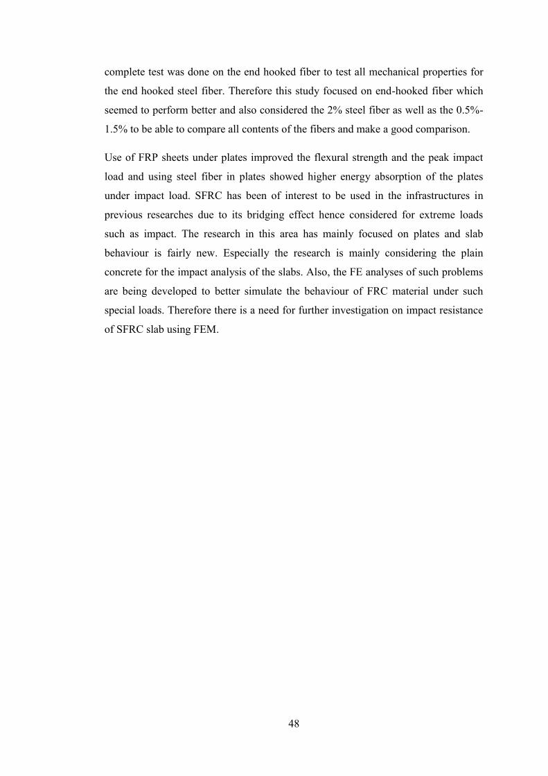
48
complete test was done on the end hooked fiber to test all mechanical properties for
the end hooked steel fiber. Therefore this study focused on end-hooked fiber which
seemed to perform better and also considered the 2% steel fiber as well as the 0.5%-
1.5% to be able to compare all contents of the fibers and make a good comparison.
Use of FRP sheets under plates improved the flexural strength and the peak impact
load and using steel fiber in plates showed higher energy absorption of the plates
under impact load. SFRC has been of interest to be used in the infrastructures in
previous researches due to its bridging effect hence considered for extreme loads
such as impact. The research in this area has mainly focused on plates and slab
behaviour is fairly new. Especially the research is mainly considering the plain
concrete for the impact analysis of the slabs. Also, the FE analyses of such problems
are being developed to better simulate the behaviour of FRC material under such
special loads. Therefore there is a need for further investigation on impact resistance
of SFRC slab using FEM.

49
CHAPTER THREE
Methodology
The experimental study aims to understand the material behaviour of SFRC. To
predict the effect of impact load on concrete slab different approaches such as
experimental and numerical methods could be used. Experimental research gives a
realistic insight to the problem and results, while numerical model is another
direction of the research activities to study the behaviour of structural members in
which with the aid of simulation tools the real behaviour can be represented under
ideal condition. Experimental work could be impractical or expensive; however the
significant development in the computer technology development in the recent years
makes the numerical techniques more popular for obtaining detailed results. This
provides researchers with the opportunity to extend the application of the numerical
models to perform parametric studies by virtual experiments. On the other hand, it is
important to validate the numerical results with an experiment.
It is worth mentioning that a numerical modelling of RC slabs that are loaded under
impact loads is a concept that has not yet been accurately established. Furthermore,
current codes are unable to suggest a clear and realistic approach for the design of
slabs under impact load. However, a verified method for studying and predicting
possible failure mode is a crucial requirement. For better numerical modelling
extensive experimental results on material behaviour is required to be able to model
the material as accurate as possible in the finite element software.
The material experiment will be conducted to give a sight into the real material
behaviour of the SFRC and study its mechanical behaviour using the end-hooked
SFRC and also make the results available to other researchers for future research
works.

50
CHAPTER FOUR
Experimental Work
4.1. Material and mix design
Concrete is a composite material that its constituents contains cement, fine aggregate,
coarse aggregate and water. The concrete mixture was prepared of the concrete
includes mixing of fine aggregate, coarse aggregate and cement and then water is
added to the mix. For each batch cylindrical specimens, cubes and beams were casted
and tested to determine the compressive strength, split tensile strength and flexural
strength of the concrete.
The end-hooked steel fibres are chosen for this research which are more common in
the industry and perform better rather than other types (such as straight steel fibres)
due to better anchorage with concrete. According to previous studies and
recommendation of industrial companies such as Maccaferri Limited and Bekaert
(Dramix), the volume fraction of these fibres will vary from 0.5 % to 2.0%. Table 4
below summarizes the properties of steel fibres to be used in this study.
Table 2. Steel fiber properties
4.2. Concrete mix design
The plain concrete is designed for a target compressive strength of 35 MPa. For the
SFRC the same proportions are used with different dosage of steel fibers. Table 5
below shows different concrete types casted for this study as well as the concrete mix
design proportions for this experimental work. Portland cement type 42.5, sharp sand
for fine aggregate, and shingle gravel aggregate with a maximum size of 10 mm were
used. Figure 18 shows all materials used for the mix.
Type of
Fibre
Length
(mm)
Diameter
(mm)
Aspect ratio
(L/D)
Tensile Strength
(MPa)
Hooked end 33 0.55 60 1200

51
Table 3. Mix proportions of the concrete mixtures for 1m3
Mixture
name
Cement
(kg)
Water
(L)
Aggregate
w/c %
Fiber*
Fiber
(kg)
Fine
Aggregate
(kg)
Coarse
Aggregate
(kg)
10 mm
PC 375.0 167 696.0 1044.1 0.44 0 0
SFRC0.5 375.0 167 696.0 1044.1 0.44 0.5% 11.9
SFRC1.0 375.0 167 696.0 1044.1 0.44 1.0% 23.74
SFRC1.5 375.0 167 696.0 1044.1 0.44 1.5% 35.6
SFRC2.0 375.0 167 696.0 1044.1 0.44 2.0% 47.5
* By wt. of concrete
Figure 17. Concrete Constituents
Sharp Sand Shingle Gravel
Portland Cement Steel Fiber

52
4.3. Mixing procedure
Coarse aggregates are first added to a concrete mixer (Figure 19.a). And then sand is
added (Figure 19.b). When mixed uniformly the cement is added and let to be mixed
with the rest of the constituents for about 3 minutes. When evenly mixed and
consistent mixture of dry constituents is achieved (Figure 19.c), water is added
gradually to the appropriate amount based on the designed w/c ratio to obtain a good
workability. (Figure 19.d) In the case of steel fibre reinforced concrete the steel
fibres are added (% by weight of concrete) before the addition of water into the mix
(Figure 20) to allow for proper distribution of the fibres in the matrix.
Figure 18. (a) Addition of coarse aggregate, (b) Addition of sand, (c) Dry
constituents mixed uniformly, (d) Water added to the mixture
Figure 19. Adding steel fiber to the mix
a b
a
c
a
d
a
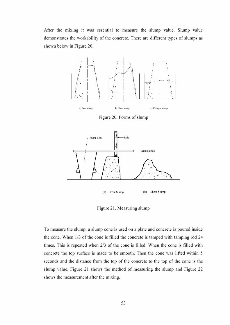
53
After the mixing it was essential to measure the slump value. Slump value
demonstrates the workability of the concrete. There are different types of slumps as
shown below in Figure 20.
Figure 20. Forms of slump
Figure 21. Measuring slump
To measure the slump, a slump cone is used on a plate and concrete is poured inside
the cone. When 1/3 of the cone is filled the concrete is tamped with tamping rod 24
times. This is repeated when 2/3 of the cone is filled. When the cone is filled with
concrete the top surface is made to be smooth. Then the cone was lifted within 5
seconds and the distance from the top of the concrete to the top of the cone is the
slump value. Figure 21 shows the method of measuring the slump and Figure 22
shows the measurement after the mixing.

54
Figure 22. Slump measurement after mixing
SFRC0.5% PC
SFRC1.0% SFRC1.5%
SFRC2.0
%

55
Figure 23. Covering inside the moulds with specific oil
Figure 22 shows that with the same water to cement ratio for all mixes the slump
value is changing. With the addition of fibers the consistency of the mix is influenced
hence the slump value decreases. The surface area of the fiber is a factor to consider.
In addition to the coarse aggregate the sand and cement must also coat around the
fibers. If the fraction of sand and cement is insufficient, then the effect on the slump
and workability will be more, meaning that with the same amount of sand and
cement ratio, increasing the fiber volume will require more sand and cement to coat
the fibers and the consistency of the mix is less as well as higher air content in the
mix. Overall, the workability of SFRC was less than plain concrete due to these
reasons. This effect was more visible with the addition of higher percentage of fibers.
After the preparation of the concrete, the moulds were covered with specific oil as
shown in Figure 24 and concrete was poured in the moulds and vibrated on a shaking
table for about 2 minutes (Figure 24. (a)) until the excessive air is removed from the
concrete. Figure 25.b shows moulds with concrete after vibration.

56
Figure 24. (a) sample moulds on shaking table, (b) Concrete moulds
The moulds where then covered by a wet cloth as shown in Figure 25. After 24 hours
the concrete specimen was de-moulded and the specimens were labelled with the
type of concrete and put in water tank in the curing room with room temperature to
be cured until the test date. (Figure 26)
Figure 25. Covering of the specimen after casting with wet cloth

57
Figure 26. Concrete specimens cured in water tank
4.4. Test set up
The tests for monitoring the performance of steel fiber reinforced concrete were
conducted using ADVANTEST 9 laboratoy system, with Servo-hydraulic control
console at City Univesity London. The tests are categorised as below:
Cube Compression Test:
o 21 Day
o 28 Day
Cylinder Compression Test
Split Tensile Test
Flexural Test
4.4.1. Cube Compression Test
For each batch of concrete, numbers of cubes were casted and tested under uniaxial
compression load. (Figure 27) This test was carried out at two different ages of the
concrete; 21 days and 28 days. As recommended in BS EN 12390-3:2002 for
conducting cube compression tests a constant rate of loading within the range of 0.2
MPa/s (N/mm2 s) to 1.0 MPa/s (N/mm2 s) is recommended. Therefore for this test a
load rate of 4000 N/s (i.e. 0.4 MPa/s) is used for all specimens at constant rate
throughout the test until the specimen fails.

58
Figure 27. Cube compression test set up
21 Day Test Results
The results of the cube compression tests are presented in Table 4 showing the
results after 21 days of casting for all concrete types. Figure 28 also compares the
results showing the progress trend of the results.

59
Table 4. Cube Test Results
Specimen Sample
No. Specimen
Max Load
(kN) Stress (MPa)
Average
Stress
PC
1
Cube
100×100×100
mm
375.1 37.5
35.4 2 364.2 36.4
3 323.1 32.3
SFRC 0.5%
1 407.4 40.7
37.8 2 366.4 36.6
3 369.1 36.9
4 371.0 37.1
SFRC 1.0%
1 439 43.9
43.6 2 276 27.6*
3 432.9 43.3
4 436.5 43.6
SFRC 1.5%
1 451.8 45.2
43.2 2 421.9 42.2
3 420.5 42.05
SFRC 2.0%
1 469.9 47.0
47.5 2 465.6 46.6
3 405.9 40.6*
4 474.8 47.5
* This result is disregarded
Figure 28. Cube Compression Test Results – 21 Day
30
32
34
36
38
40
42
44
46
48
50
PC SFRC 0.5% SFRC1.0% SFRC 1.5% SFRC 2.0%
Co
mp
resi
ve
stre
ngth
(M
Pa)
Cube Compression - 21 Day

60
It can be seen that the strength has an increasing trend with the increase of
volume fraction of fibers and the increase in strength from SFRC0.5% to
SFRC1.0% is noticeable while increasing 0.5% volume of fibers from 1.0% to
1.5% doesn’t have significant effect on the compression strength. This could be
attributed to the air content of the concrete, which previous researchers believe
that the air content increases with the increase of steel fiber volume fraction,
hence decreasing the compressive strength. However the addition of 2% of steel
fibers in the plain concrete increased the compressive strength of cubes at 21 day
age by 25.5% meaning that the air content of the concrete in this mixture is not
affected by the fibers and it performs better than other mixes. However, the effect
of more fibers is more pronounced in the damage that is visible on the cubes as
shown in pictures below.
Figure 29. Cube Compression Specimen Results (21 Day)
Plain
Concrete

61
SFRC 0.5%
SFRC 1.0%
SFRC 1.5%
SFRC 2.0%
Figure 30. Cube Compression Specimen Results (21 Day)-continued

62
28 Day Test Results
The increasing path for the strength is also visible for concrete at 28 days
(Figure 31). Compared to the strength of concrete at 21 days the concrete at
its full strength has higher strength by an average of 1.8%.
Table 5. Cube Compression Test Results for 28 Days
Specimen Sample
No. Specimen
Max Load
(kN) Stress (MPa)
Average
Stress
PC
1
Cube
100×100×
100 mm
377.3 37.73
37.3 2 373.5 37.35
3 366.9 36.69
SFRC0.5
%
1 373.4 37.3
39.8 2 452.3 45.2
3 413.5 41.3
4 354.1 35.4
SFRC1.0
%
1 441.2 44.12
44.4 2 459.7 45.97
3 430.1 43.01
4 445.7 44.57
SFRC1.5
%
1 374.2 46.1
45.1 2 383.9 45.2
3 395.9 44.1
SFRC2.0
%
1 496.4 49.6
49.2 2 487.2 48.7
3 494.5 49.4
4 489.9 49.0

63
35
37
39
41
43
45
47
49
51
PC SFRC 0.5% SFRC1.0% SFRC 1.5% SFRC 2.0%
Co
mp
ress
ive
stre
ngth
(M
Pa)
Cube Compression - 28 day
Figure 31. Cube Compression Test Results – 21 Day
Figure 32 reveals how the concrete damage is less severe and the presence of the
fibers in more amounts has been more effective. The performance of samples with
1%, 1.5% and 2% are all as equally as good and have been effective although 2%
fiber showed the least damage.
Figure 32. Cube Compression Specimen Results (28 Day)
PC

64
Figure 33. Cube Compression Specimen Results (28 Day)-continued
SFRC 0.5%
SFRC 1.0%
SFRC 1.5%
SFRC 2.0%

65
4.4.2. Cylinder Compression Test
Cylindrical Compression tests are conducted in accordance with BS EN 12390-
3:2002. The load was applied in displacement control manner to be able to monitor
the strain in the concrete as well as the post peak behaviour. Although this was the
aim but some samples after having failure cracks the test was terminated by the
machine and the full behaviour could not be captured. The displacement was
controlled through displacement transducers (as shown in Figure 33). Three
displacement transducers were attached to each cylinder in equal angular distances of
120˚. The transducer was hammered into concrete and tightened with an elastic band
around all three transducers. The displacement control rate that was used was 1µm/s.
Figure 33 shows the set up for this test.
Figure 34. Cylindrical Compression Test Set up.
Displacement
Transducer

66
The results of this compression test for all concrete types is summarised in Table 6.
Table 6. Cylinder Compression Test Results
Specimen Sample
No. Specimen
Max Load
(kN) Stress (MPa)
Average
Stress
PC
1
Cylinder
H200×Ø100
mm
269.9 34.37
35.23 2 264 33.61
3 292.9 37.29
4 280.0 35.66
SFRC 0.5%
1 282.1 35.92
36.34 2 286.68 36.50
3 284.85 36.27
4 287.93 36.66
SFRC 1.0%
1 262.9 33.47
37.39 2 317.3 40.4
3 273.9 34.87
4 320.4 40.8
SFRC 1.5%
1 298.4 37.99
37.64
2 293.9 37.42
3 299.3 38.11
4 296.6 37.76
5 289.9 36.91
SFRC 2.0%
1 301.96 38.45
38.10 2 298.24 37.97
3 296.79 37.79
4 299.97 38.19
* This result is disregarded
The compressive strength of the fibers is increased by 8% when 2% of fibers is used
(i.e. 10 kg/m3) while in the results of Sukumar and John (2014) the compressive
strength increased by 3.5 % with the addition of 20 kg/m3 of end hooked steel fiber
with aspect ratio of 80. Also Kothadia and Mishra (2015) observed that compressive
strength increases from 8% to 26% with addition of hooked end steel fibres by 2.0%,
2.5% and 3.0% by cement weight. The results of the 2.0% fiber addition is identical
to that of this studies experiment with 2.0% of steel fibers. However, the studies of
Wafa back in 1990 showed that the end hooked fiber addition had no effect on the

67
0
5
10
15
20
25
30
35
40
45
0 0.0005 0.001 0.0015 0.002 0.0025 0.003
Str
ess
(MP
a)
Strain
Cyliner Compression
PC SFRC0.5% SFRC1.0% SFRC1.5% SFRC2.0%
compressive strength values. But, the brittle mode of failure associated with plain
concrete was transformed into a more ductile one with the increased addition of
fibers similar to the result of this research where the specimens showed crack control
and better post peak behaviour with the addition of 2.0% fibers.
Figure 35. Cylinder Compression Results
The strain is calculated based on the average displacement of the three transducers
and the stress-strain graph for each concrete type is plotted in Figure 34.
As can be seen from the graph the use of steel fiber affects the post peak behaviour
of the concrete. The plain concrete does not show gradual decrease after it reaches
the maximum strength, while, specimen with fibers demonstrate gradual decrease in
strength after post-peak. This is especially evident in SFRC1.0%-2.0%. The
behaviour of SFRC with 2.0% and 1.5% is very close regarding the stiffness of the
concrete and strength. SFRC2.0% which has the highest quantity of the steel fibers is
the stiffest with higher compressive modulus of elasticity. While the effect of fibers
on the maximum strength is not very significant, but the damage pattern in the
specimens demonstrates the effect of fibers better and how higher fiber volume
fraction improved the level of damage in concrete.
Below the damage in all specimens are shown and compared.

68
Figure 36. Plain concrete sample after the test
As can be seen in the Figure above the damage for plain concrete specially PC2 is
more severe which also had the least strength amongst other samples. This sample is
totally damaged and crushed into pieces. When 0.5% of fibers is added to the mix the
concrete cylinders show cracks through the specimen as well as spalling of the
concrete. Sample PC1 and SFRC0.5-3 has similar damage of spalling, in which both
have shown spalling close to the end of the cylinder, however with less depth in
SFRC sample.
Figure 37. SFRC0.5 sample after the test
PC1 PC2
PC1
PC4
PC1
SFRC0.5-2 SFRC0.5-3 SFRC0.5-4

69
For samples with 1.0%, 1.5% and 2.0% these cracks do not occur and the damage is
in the form of concrete spalling from the sides mainly closer to the top or bottom as
such in Figures.
Figure 38. SFRC1.0% samples after the cylinder compression test
The spalling of concrete is also evident in other SFRC samples. For example both
first and second samples of SFRC1.0% have this type of failure. Amongst 1.5% steel
fiber samples SFRC1.5-2 and SFCR1.5-3 as well as SFRC2.0-4 are similarly failed.
However, it should be noted that the damage in samples with 2% is less severe and
with smaller area as opposed to samples with less fibers such as SFRC1.0.
Similarly PC4 and SFRC0.5-2 could be compared since both are showing the
damage from centre perimeter of the cylinder towards the end and both having close
strength of 35.66 MPa and 36.5 MPa respectively. It shows that addition of fibers
could be effective in preventing concrete from being crushed into pieces.
SFRC1.5-2 shows a diagonal damage to the cylinder which was observed for other
samples as well. However, none of the 2.0% samples showed this kind of damage
and the least damage was observed for this concrete type.
SFRC1.0-1 SFRC1.0-2 SFRC1.0-3

70
Figure 39. SFRC1.0% samples after the cylinder compression test
It is evident that the concrete damage for SFRC with 2.0% fibers is minor and this
reveals that the concrete is better held in one piece when higher fiber is used.
As the presence of steel fibers are not evident or visible in areas damaged it can be
concluded that the presence of the steel fibers strongly gives the concrete stiffness
and coherence to stand the compression force and prevent the breakage of the
concrete which is of great advantage and importance in construction industry when
concrete is subjected to different loads.
Figure 40. SFRC1.0% samples after the cylinder compression test
SFRC1.5-1 SFRC1.5-2 SFRC1.5-3
SFRC2.0-2 SFRC2.0-3 SFRC2.0-4
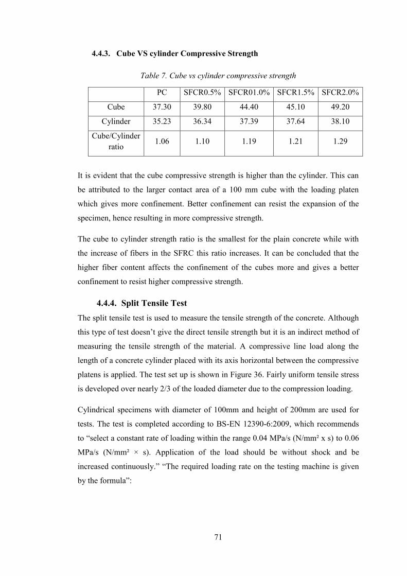
71
4.4.3. Cube VS cylinder Compressive Strength
Table 7. Cube vs cylinder compressive strength
PC SFCR0.5% SFCR01.0% SFCR1.5% SFCR2.0%
Cube 37.30 39.80 44.40 45.10 49.20
Cylinder 35.23 36.34 37.39 37.64 38.10
Cube/Cylinder
ratio 1.06 1.10 1.19 1.21 1.29
It is evident that the cube compressive strength is higher than the cylinder. This can
be attributed to the larger contact area of a 100 mm cube with the loading platen
which gives more confinement. Better confinement can resist the expansion of the
specimen, hence resulting in more compressive strength.
The cube to cylinder strength ratio is the smallest for the plain concrete while with
the increase of fibers in the SFRC this ratio increases. It can be concluded that the
higher fiber content affects the confinement of the cubes more and gives a better
confinement to resist higher compressive strength.
4.4.4. Split Tensile Test
The split tensile test is used to measure the tensile strength of the concrete. Although
this type of test doesn’t give the direct tensile strength but it is an indirect method of
measuring the tensile strength of the material. A compressive line load along the
length of a concrete cylinder placed with its axis horizontal between the compressive
platens is applied. The test set up is shown in Figure 36. Fairly uniform tensile stress
is developed over nearly 2/3 of the loaded diameter due to the compression loading.
Cylindrical specimens with diameter of 100mm and height of 200mm are used for
tests. The test is completed according to BS-EN 12390-6:2009, which recommends
to “select a constant rate of loading within the range 0.04 MPa/s (N/mm² x s) to 0.06
MPa/s (N/mm² × s). Application of the load should be without shock and be
increased continuously.” “The required loading rate on the testing machine is given
by the formula”:

72
𝑅 =𝑠 × 𝜋
2 × 𝐿 × 𝑑
Where:
R is the rate of increase of load, in newtons per second;
L is the length of the specimen, in millimetres (see Figure 2);
d is the designated dimension of the specimen, in millimetres;
s is the increase in rate of stress, in megapascals per second, or newtons per square
millimetre per second.
According to this guidance a loading rate of 1257 N/s is used. Again in BS-EN
12390-6:2009 the tensile splitting strength is given by the formula:
𝑓𝑐𝑡 =2 × 𝐹
𝜋 × 𝐿 × 𝑑
Where:
fct is the tensile splitting strength, in megapascals or newtons per square millimetre;
F is the maximum load, in newtons;
L is the length of the line of contact of the specimen, in millimetres;
d is the designated cross-sectional dimension, in millimetres.
The results are calculated based on this formula and presented in Table 7.

73
Figure 41. Split tensile test set-up
The tensile stress results are compared for all concrete types in Figure 41.
Figure 42. Split Tensile Strength Comparison
2.5
3
3.5
4
4.5
5
PC SFRC 0.5% SFRC1.0% SFRC 1.5% SFRC 2.0%
Str
ess
(MP
a)

74
Table 8. Cylinder Split Tensile Test Results
From the strength values it is evident that the split tensile strength of the concrete is
increased with the same trend as concrete compressive strength. The increase for the
strength from 0.5% to 1% has been more pronounced. The behaviour of 1.0% and
1.5% is more similar in terms of strength. On the other hand, it is important how the
fibers affect the failure of the specimens. Figures below compare the specimens after
failure. Results show that there is an increase of around 53.3% in splitting tensile
strength of the tested specimens with increase in steel fiber content from 0% to 2.0%.
Previous test results by Khaloo et al (2014) show an increase of 28.5% in splitting
tensile strength of normal weight high-strength concrete with addition of 2% hooked
steel fiber content to concrete. Also 1.25% addition of straight fibers in the research
Specimen Sample
No. Specimen
Max Load
(kN) Stress (MPa)
Average
Stress
PC
1
Cylinder
H200×Ø100
mm
82.85 2.64
2.99 2 90.4 2.88
3 102 3.25
4 100.9 3.21
SFRC 0.5%
1 100.5 3.20
3.14 2 95.3 3.03
3 103.5 3.29
4 95 3.02
SFRC 1.0%
1 137.5 4.38
4.01 2 127.2 4.05
3 128.6 4.09
4 111.2 3.54
SFRC 1.5%
1 129.5 4.12
4.12 2 130.8 4.16
3 131.6 4.19
4 126.0 4.01
SFRC 2.0%
1 139.96 4.46
4.58 2 142.85 4.55
3 146.92 4.68
4 145.45 4.63

75
by Iqbal et al. (2015) shows that there is around 37% increase in splitting tensile
strength.
Wafa (1990) tested the end hooked fibers under split tensile strength and for volume
fractions of 0.5%, 1.0%, 1.5%, and 2.0%. The results showed higher tensile strength
by 22%, 53%, 50% and 50% respectively. The fibers in this research showed 5%,
34.1%, 38%, and 53% increase in the split tensile strength. Unlike the results for the
0.5% in this study and Wafa’s the results for the 2.0% fiber is similar.
Figure 43. PC Samples after Split Tensile Test
As can be seen the damage pattern in plain concrete is wide cracks through the
middle of the cylinder along the line of the applied load. The crack in sample PC3
goes through the whole cross section of the cylinder and splits the cylinder into two
pieces. It should be noted that this kind of behaviour was not evident in any of fiber
reinforced samples. While SFRC samples only failed with cracks. The crack width
varied for different volume fraction of steel fiber samples.
PC4 PC3 PC2

76
Figure 44. SFRC0.5 Samples after Split Tensile Test
Figure 45. SFRC1.0% samples after split tensile test
Figures 44 and Figure 45 shows that samples have similar failure cracks and pattern
however samples with 1.0% fibers show less crack along the sides of the cylinder.
Comparing Figures 46 and 47, samples have very similar failure pattern as both
visibly have hair cracks along the sample which is significantly different than plain
concrete. For example for Samples SFRC1.5-4 and SFRC2.0-4 the cracks are un-
noticeable. This behaviour is solely due to the effect of fibers which increases the
SFRC0.5-2 SFRC0.5-1 SFRC0.5-4
SFRC1.0-1 SFRC1.0-2 SFRC1.0-4

77
load carrying capacity of the concrete when subjected to tensile stress. The fibers
require extra load to be pulled out hence adding to the strength of the material as well
as bridging the cracks to stop the quick propagation of the cracks which normally
occurs for normal concrete.
Figure 46. SFRC1.5% samples after split tensile test
It should be noted that the hooked end of the fibers allow for good bonding between
the fibers and the concrete hence giving effective behaviour of fibers in the concrete
matrix.
Figure 47. SFRC2.0% Samples after split tensile test
SFRC1.5-2 SFRC1.5-3 SFRC1.5-4
SFRC2.0-2 SFRC2.0-3 SFRC2.0-4

78
4.4.5. Flexural Beam Test
Flexural beam test is another indirect method of testing and evaluating the tensile
strength of the concrete. For each batch numbers of beams were casted to be tested
under compression load. The beams had the cross section dimension of 100×100mm
and a length of 500mm. The test was a 4-point bending test. Referring to BS EN
12390-5:2000 and as shown in Figure 48, the clear span was set to 300mm and the
upper bearer distance was set to 100mm. The displacement at the centre of the beam
was measured by the use of two displacement transducers at both sides of the beam.
The test set-up is shown in Figure 49.
Figure 48. Arrangement of loading of test specimen (BS EN 12390-5:2000)
Figure 32. Flexural test set-up
Figure 49. Flexural Beam Test Set Up
Displacement Transducer

79
The test was conducted under displacement control and the load was applied with a
rate of 0.1µm/s. The flexural strength of the concrete derived from BS EN 12390-
5:2000 and is given by the following equation:
𝑓𝑐𝑓 =𝑙 × 𝐹
𝑑1 × 𝑑22
Where:
fcf is the flexural strength, in megapascals or newtons per square millimetre;
F is the maximum load, in newtons;
l is the distance between the supporting rollers, in millimetres;
d1 and d2 are the lateral dimensions of the specimen, in millimetres.
Test results are summarised for all specimen in Table 9.
Table 9. Flexural Test Results
Specimen Sample
No. Specimen
Max Load
(kN)
Stress
(MPa)
Average
Stress
PC
1
Prism
500×100×100
mm
11.41 3.42
3.60 2 12.44 3.73
3 12.18 3.65
SFRC
0.5%
1 12.72 3.82
3.84 2 12.31 3.69
3 13.37 4.01
SFRC
1.0%
1 15.34 4.60
4.51 2 15.71 4.71
3 14.01 4.20
SFRC
1.5%
1 15.48 4.64
4.66 2 15.89 4.77
3 15.21 4.56
SFRC
2.0%
1 16.26 4.88
5.19 2 17.64 5.29
3 18.04 5.41

80
The Average stress results clearly show that the flexural strength of the test is
increasing proportionally with the increase of the steel fiber. With the addition of
steel fibers in volume fraction of 0.5%, 1.0%, 1.5%, and 2.0% the flexural strength of
concrete increased by 6.6%, 25.2%, 29.4% and 44.1% respectively. 2.0% of fibers
had the highest effect on the flexural strength while 1.0% and 1.5% had almost
similar effect on the strength. Overall the literature suggested the increase of flexural
strength by 1.5-3 times higher than plain concrete which in this study the flexural
strength is also increased by 1.5 when 2% fibers is used. One of the most important
factors that can be concluded from the flexural test is the tensile capacity of the
beams. When the beam is loaded the bottom fiber of the beam is under tension. The
higher the tensile strength of the beam the better the beam will perform especially
after cracking.
The load-displacement graph is plotted by calculating the average displacement of
mid-span and shown in Figure 50.
Figure 50. Flexural Beam Test Results
The failure process for the fiber reinforced concrete is that when the beam reaches its
maximum flexural strength it starts to crack from the bottom centre point of the
0
2
4
6
8
10
12
14
16
18
20
0 0.1 0.2 0.3 0.4 0.5 0.6 0.7 0.8 0.9 1
Lo
ad (
kN
)
Displacement (mm)
PC SFRC0.5% SFRC1.0% SFRC1.5% SFRC2.0%
81
beam, where the concrete is under tensile stress. When the crack starts to form the
fibers in the concrete matrix start to take part and prevent the cracks from opening
and further propagating similar to that observed in the split tensile test. The effect
fibers in between cracks are known as bridging effect and it is more effective when
the number of fibers increases. The bridging results in higher load capacity of the
beams hence the post-peak behaviour of the beam changes.
Figure 50 shows that the slope of the graph at the post-peak stage gets higher with
the presence of the fibers. Comparing plain concrete with SFRC0.5% slight
improvement is visible for the concrete with 0.5% fibers. However, In the case of
1.5% and 2.0% of fibers, the post-peak stage has a very gradual reduction trend and
at displacement (0.5-0.7mm) almost linear line is obtained. This reflects the high
tensile capacity of the beam; therefore higher energy dissipation can be attributed to
beams with higher steel fibers. The energy dissipation capacity of the specimen can
also be evaluated from the area under the graph.
One of the findings of the flexural strength tests was that the concrete mix with 2.0%
steel fiber content exhibits strain hardening behaviour as shown in Figure 51 which is
partial representation of Figure 50 with a closer look at the load-displacement
behaviour up to 0.1mm displacement. In this part the load decreases from 18kN to
16kN but due to the presence of the fibers with further increase in displacement the
load starts to increase up to 17kN and small strain hardening occurs which can be
attributed to the higher load that steel fibers can carry. From there the beam succeed
to maintain the load capacity at an almost constant load of 16kN.

82
Figure 51. Flexural Beam Test Results (Early stages)
Figures below show the failed specimens for each concrete after the test. Beams that
were made of plain concrete show the most severe damage and in all three specimens
the beams are broken from the middle.
0
2
4
6
8
10
12
14
16
18
20
0 0.01 0.02 0.03 0.04 0.05 0.06 0.07 0.08 0.09 0.1
Lo
ad (
kN
)
Displacement (mm)
PC SFRC0.5% SFRC1.0% SFRC1.5% SFRC2.0%
Strain hardening

83
Figure 52. PC beam test results
This behaviour is similar to that of the split tensile strength that was observed for
PC2 in which the crack in the specimen made the concrete in to two pieces. In these
beams when the crack initiated at the bottom surface of the beam it propagated with a
slight increase in load and failed quicker than SFRC samples. Figure 52 shows the
crack propagation during the test.
Figure below shows the specimen for SFRC0.5% and cracks formed at the bottom of
the beam after the tests are completed. As it is evident these samples are showing a
very good performance in terms of bridging the cracks.
PC1
PC2
PC1
PC3

84
Figure 53. SFRC1.0 Beam Test Results
SFRC0.5-1
SFRC0.5-2
SFRC0.5-3

85
Similarly the beams with 1.0% fibers show very similar results when compared to
SFRC0.5 even though the amount of fibers is doubled. Samples with 1.0% fiber
show the cracks to be mainly at the bottom of the beam and slightly towards the
centre line of the beam from the side while for SFRC0.5 the crack has more
propagation on the sides of the beam as can be seen clearly in sample SFRC0.5-2
that the crack almost reached the top of the beam. This shows the crack was able to
propagate in more depth.
Figure 54. SFRC1.0 Beam Test Results
SFRC1.0-1
SFRC1.0-2
SFRC1.0-3

86
Samples SFRC1.5-1 and SFRC1.5-3 shows wider crack at the bottom of the beam
compared to previous samples discussed, however these beams had higher strength.
It can be said that the higher load was required to form the cracks and more
resistance from fiber was present resulting in more strength. While the crack for
SFRC1.5-2 is very fine.
Figure 55. SFRC1.5 Beam Test Results
SFRC1.5-3
SFRC1.5-1
SFRC1.5-2

87
Figure below shows the performance of SFRC2.0 and it can be seen that it shows the
finest cracks at the bottom of the beam and also it is worth mentioning that the depth
of the cracks is less than any other SFRC concrete. In SFRC2.0-2 and SFRC2.0-3 the
cracks on the side of the beam has only propagated up to 1/3th of the beam depth.
This means that the propagation of the crack in the concrete were it is subjected to
tensile stresses is significantly due to the presence of the fibers. And the optimum
amount of fibers is considered to be 2%.
Figure 56. SFRC2.0 Beam Test Results
SFRC2.0-2
SFRC2.0-1
SFRC2.0-3
Side crack

88
The cracks at the beam with fibers was delayed while the test was in process and as it
can be seen from the figures cracks are not wide and the fibers have successfully
stopped the propagation of the cracks. Figure 57 below shows a closer view of the
fibers bridging the cracks.
Figure 57. Steel fibers bridging the concrete beam crack under flexure
The fibers geometry which is end hooked have great influence on the bonding of
the fibers with the concrete matrix. And it seems that they have been spread
reasonably uniform to better enhance the concrete performance.
4.4.6. Relation between split tensile strength and flexural strength
Table 10. Relation between split tensile strength and flexural strength
PC SFRC0.5% SFRC1.0% SFRC1.5% SFRC2.0%
Split 2.99 3.14 4.01 4.12 4.58
flexural 3.60 3.84 4.51 4.66 5.19
Flexure/split
ratio 1.2 1.2 1.12 1.13 1.13
From Table 10 it can be seen that the ratio between flexural strength and the split
tensile strength is almost the same for all mixes. Plain concrete and SFRC0.5% has
similar ratio while SFRC1.0% and SFRC1.5% and SFRC2.0% has the same ratio.
Steel Fiber

89
This reveals that the relation of the tensile strength and the flexural strength has the
same value varying the fiber volume of the steel fibers in SFRC.
4.5. Conclusion
From the material test it was evident that the use of fibers had great effect on the
performance of the plain concrete on all mechanical aspects of compressive strength,
split tensile strength and flexural strength. The increase of the fibers from 0.5% to
2.0% showed better performance and amongst these volume fractions the SFRC
2.0% performed the best. Flexural strength increased by 44.1% with the addition of
2.0% fibers. Also, split tensile strength increased by 53.3% and Compressive
strength increased by 4.8%. The effect of fiber was more evident and effective on the
flexure and tensile strength since the fibers bridge the cracks, giving concrete more
capacity under tensile loads.
The optimum value of steel fibers is suggested to be 2.0% as it affects the
mechanical performance greatly. Also the literature and industry considers the 2.0%
to be a practicable and cost effective amount. However higher volume fractions also
have been studied up to 3% and at some cases 5% for ultra-high performance
concrete which is a very brittle material compared to conventional plain concrete. It
should be noted that this amount of fibers decreases the consistency and workability
of the concrete which can be undesirable, therefore the use of additives to enhance
the workability would be essential. In conclusion the use of 2.0% of fibers by the
volume of concrete is considered to be satisfactory.
90
CHAPTER FIVE
Conclusion and Recommendation
The behaviour of the structural members under extreme loads is quite vital in some
applications in structural engineering industry. The development of new materials
such as steel fibre reinforced concrete has shown that these can be effective in
structural member performance. Research up to date on SFRC has been mostly
focused on static performance of members and there is lack of research on the effect
of these materials on impact behaviour of slabs with varying parameters in the
concrete such as steel fibre type and volume fraction. This research aims to
investigate SFRC material behaviour and conclude how SFRC can enhance the
performance of concrete hence structural members.
Experimental investigation was carried out on the behaviour of steel fibre reinforced
concrete material using end hooked steel fiber with different volume fractions of the
fibers consisting of: 0.5%, 1.0%, 1.5% and 2.0% as well as plain concrete with no
fibers for comparison. Tests included the cube compression test, cylindrical
compression test, split tensile test and flexural test to evaluate the basic material
behaviour.
The results showed that the use of fibers enhanced all aspects of material capacity
namely compression strength, tensile strength and flexural strength. This was more
evident with the increase in the amount of fibers. The performance of SFRC2.0%
was the beast out of all concrete types while PC showed the highest damage with the
least capacity.
Amongst all tests the performance of the specimens under split tensile test and
flexural test, which the tensile properties of the concrete are of importance, showed
better enhancement. This was due to the effect of fibers and bridging the cracks when
concrete starts to crack at its capacity. The presence of fibers increases the load
capacity of the samples and makes the concrete a more ductile material as opposed to
a conventionally known brittle material. This is very important when designing
structural members especially for those under extreme loads such as impact load.
There is lack of research on the behaviour of SFRC under impact using FE analysis,
and researchers focused on developing models for normal concrete so far.

91
According to literature material models such as Concrete Damage Plasticity (CDP)
model and Drucker Prager (DP) model are amongst the best to predict the material
behaviour.
Recommendations
Predict the behaviour of SFRC slabs under impact load with the aim of FE
and material models to best predict the structural performance.
Complete experiments including:
o The uniaxial tension,
o The biaxial failure in plane state of stress
o The triaxial test of concrete
To obtain all material characteristics required for the input data of the
ABAQUS to accurately model the behaviour of such materials and avoid
assumptions.
Improve modelling of impact load in the finite element analysis programmes.
Conduct a parametric study on the behaviour of SFRC slabs under impact
load using FE analysis investigating following parameters:
o Volume fraction of steel fibers
o Aspect ratio of fibers
o Type of fibers
o Slab thickness
Investigate the energy absorption of the slabs under the parametric study.
Material models in ABAQUS should be further investigated for SFRC and
focusing on phenomenon such as impact.

92
REFERENCES
1. Achilleos, C. Hadjimitsis, D. Neocleous, K. Pilakoutas, K. Pavlos, O. and
Neophytou, S.K. (2011) “Proportioning of Steel Fibre Reinforced Concrete
Mixes for Pavement Construction and Their Impact on Environment and
Cost”, Sustainability, Vol. 3, pp. 965-983.
2. ACI Committee 544. (1989). Measurement of properties of fiber reinforced
concrete: American concrete Institute.
3. ACIFC, 1999 “Steel Fiber on Surface”, Association of Concrete Industrial
Flooring Contractors, ACIFC Flooring Technical Note 06.
4. Alfonso, J.D. (1991) “Seismic resistance of fibre-reinforced slab-column
connection.” Master Thesis, William March Rice University.
5. Avenil, S.E. and Samuel, K.G.M. (2014) “Steel Fibre Reinforced Concrete
Slabs to Pendulam Impact Test”, American-Eurasian Journal of Scientific
Research, Vol. 8, pp. 198-205.
6. Belletti, B. Cerioni, R. Meda, A. and Plizzari, G. (2008) “Design Aspects on
Steel Fibre-Reinforced Concrete Pavements”, Vol. 10, pp. 899-1561.
7. Bischoff, P. (2003) “Tension Stiffening and Cracking of Steel Fibre-
Reinforced Concrete”, Journal of Material Civil Engineering, No. 15, Vol. 2,
pp. 174–182.
8. Blunt, J. Ostertag, C.P. (2008) “Use of Fibre Reinforced Concrete in Bridge
Approach Slabs”, Civil and Environmental Engineering Department
University of California, Berkeley.
9. British Standards, “Testing hardened concrete - Part 3: Compressive strength
of test specimens”, BS EN 12390-3:2002.

93
10. Buratti, N. Mazzotti, C. and Savoia, M. (2011) “Post cracking behaviour of
steel and macro-synthetic fibre-reinforced concretes”, Construction and
Building Materials. Vol. 25, pp. 2713–2722.
11. Cavill, B. Rebentrost, M. and Perry, V. (2006) “Ductal
an Ultra-High
Performance Material for Resistance to Blasts and Impacts”, Conference on
Disaster Mitigation, Canada, 23-26 May.
12. Coetze, C.H. Van der walt, N. (1990) “The Potential of Thinner Concrete
Pavements: Evidence from Accelerated testing”, Proceedings of the 6th
International Symposium on Concrete Roads, Madrid, Spain, pp. 21-32.
13. Deidea. K. (2010) “Use of steel fibre reinforced concrete for blast resistant
design”, Master Dissertation, Kansas State University.
14. Doo, Y.Y. Kyunh, H.M. Jin, Y.L. and Young, S.Y. (2009) “Enhancing
impact resistance of concrete slabs strengthened with FRPS and steel fibres”,
South Korea University.
15. Elavenil, S. and Samuel Knight, G.M. (2012) “Impact response of plates
under drop weight impact testing”, Daffofil International University”,
Journal of science and technology, Vol. 7, No. 1, pp. 1-11.
16. Ellouze, A. Ouezdou, M.B. and Karray, M.A. (2010) “Experimental Study of
Steel Fibre Concrete Slab and the Behaviour under Uniformly Distributed
Loads”, International Journal of Concrete Structures and Materials Vol. 4,
No. 2, pp. 113-118.
17. Elsaigh, W.A. (2001) “Steel fibre reinforced concrete ground slabs: a
comparative evaluation of plain and steel fibre reinforced concrete ground
slabs”, Master Dissertation, University of Pretoria.

94
18. Elsaigh, W.A. (2007) “Modelling the behaviour of steel fibre reinforced
concrete pavements”, PhD Thesis, Transportation Engineering, University of
Pretoria.
19. Faisal, F.W. (1990) “Properties and Applications of Fibre Reinforced
Concrete”, JKAU: Eng. Sci. Vol. 2, pp. 49-56.
20. Falkner, H. Teutch, M. (1993) “Comparative investigations of plain and steel fibre
reinforced concrete industrial ground slabs”, Institut fur Baustoffe, Technical
University of Brunswick, Germany, No. 102.
21. Farnam, Y. Mahoutian, M. Mohammadi, S. and Shekarchi, M. (2008)
“Experimental and numerical studies of impact behavior of fibre lightweight
aggregate concrete”, Structures: Crossing Borders.
22. Farnam, Y. Mahoutian, M. Mohammadi, S. and Shekarchi, M. (2008)
“Experimental and Numerical Studies of Impact Behavior of Fibre
Lightweight Aggregate Concrete”, Structures Congress, Vol. 10, PP. 1-10
23. Fwa, T.F. Paramasivam, P. (1990) “Thin Steel Fibre Cement Mortar Overlay
for Concrete Pavement, Department of Civil Engineering”, Cement &
Concrete Composites, Vol. 12, PP.175-184.
24. Gopalaratnam, V.S. Shah, S.P. Bastan, G.B. Criswel, M.E. Ramakrishnan, V.
Wecharatana, M. (1991) “Fracture toughness of fiber reinforced concrete”,
ACI Materials Journal, Vol. 4, No.88, pp.339-359.
25. Gopinath, S. Ayashawarya, R. Ramesh Kumar, V. Ranjan Prem, P. Murthy,
A.R.C. Madheswaran, C.K. and Nageshiyer, R. (2014) “Low velocity impact
behaviour of ultra-high strength concrete panels”, Indian Academy of Science
, Vol. 39, PP. 1497-1507.
26. Graeff, A.G. Pilakoutas, K. Neocleous, K. Vania, N.M.P. (2012) “Fatigue
resistance and cracking mechanism of concrete pavements reinforced with

95
recycled steel fibres recovered from post-consumer tyres”, Engineering
Structures, Vol.45, PP.385–395.
27. Haejin, K. (2003) “Behaviour and perfotmance of high performance concrete
for pavements”, Master thesis, University of Maryland.
28. Hrynyk, T. (2013) “Behaviour and Modelling of Reinforced Concrete Slabs
and Shells Under Static and Dynamic Loads”, PhD Thesis, University of
Toronto.(To matn nist)
29. Hrynyk, T.D. and Vecchio, F.J. (2014) “Behaviour of Steel Fibre-Reinforced
Concrete Slabs under Impact Load”, ACI Structural Journal, Vol. 111, No. 5,
pp.1213-1224.
30. Iqbal, S., Ali, A., Holschemacher, K., and Bier, T. A., (2015) “Mechanical
properties of steel fiber reinforced high strength lightweight self-compacting
concrete (SHLSCC)” Construction and Building Materials, No. 98, pp325-
333.
31. James, H. Abu Bakar, B.H. Ayad, A. A. R. Jayaprakash, J. (2010) “Dynamic
response simulation for reinforced concrete slabs”, Vol.18 , PP. 696–711.
32. Jatale, V.B. and Kalurkar, L.G. (2013) “Punching Shear High Strength Steel
Fibre Reinforced Concrete Slabs”, International Journal of Engineering
Research and Applications, Vol. 3, No. 6, pp. 269-275.(matb nist)
33. Jeffery, R.R. Salah, A.A. David, A. L. Klaus, A.R. and Gregory, R.U. (2006)
“Effect of Synthetic Fibres on Structural Behavior of Concrete Slabs on
Ground”, ACI Material Journal, No. 103, pp. 3-10.
34. Jianming, G.W.S. and Keiji, M. (1997) “Mechanical Properties of Steel Fibre
reinforced, High-strength, Lightweight Concrete”, Cement and Concrete
Composites, Vol. 19, pp. 307-313.

96
35. Jyoti, N. Ajay, G. Devender, S. Kapoor, D.R. Bhupinder, S. (2013) “An
Experimental Investigation on Structural Performance of Steel Fibre
Reinforced Concrete Beam”, International Journal of Engineering and
Advanced Technology Vol. 2, No. 6.
36. Khaloo, A., Raisi, E.M., Hosseini, P., Tahsiri, H., (2014) “Mechanical
performance of selfcompacting concrete reinforced with steel fibers,” Constr.
Build. Mater. No.51, pp.179–186.
37. Knapton, J. (2003) Ground Bearing Concrete Slabs, London: Thomas Telford
Publishing. P24.
38. Kothadia, Ρ., Μishra, C.Β., (2015), “LOGICAL ASSESSMENT OF
HOOKED END STEEL FIBRE REINFORCED CONCRETE IN M-40
GRADE FOR RIGID PAVEMENT,” IJRET: International Journal of
Research in Engineering and Technology, Vol. 4, Issue: 01.
39. Luca, G.S. Alberto, M. and Giovanni, A.P. (2006) “Steel Fibre Concrete
Slabs on Ground: A Structural Matter”, ACI Structural journal, Vol. 103, No.
4, pp.551-558.
40. Luccioni, B.M. Luege, M. (2004) “Concrete pavement slab under blast
loads”, International Journal of Impact Engineering, Vol.32, PP.1248–1266
41. Madheswaran, C.K. Dattatreya, J.K. Ambily, P.S. and Karansingh, P.R.
(2014) “Investigation on behaviour of reinforced geopolymer concrete slab
under repeated low velocity impact loading”, International Journal of
Innovative Research in Science, Engineering and Technology, Vol. 3, No.3.
42. Mahalingam, M. Pulipakka, R. Rao, N. and Kannan, S. (2013) “Ductility
Behavior of Fibre Reinforced Concrete Beams Strengthened with Externally

97
Bonded Glass Fibre Reinforced Polymer Laminates”, American Journal of
Applied Sciences, Vol. 10, No. 1, pp. 107-111.
43. Martin, O. (2010) “Comparison of different Constitutive Models for Concrete
in ABAQUS/Explicit for Missile Impact Analyses”, JRC Scientific and
Technical Reports, European Commission, Joint Research Centre, Institute
for Energy.
44. Milind, V.M. (2012) “Performance of Steel Fibre Reinforced Concrete”,
International Journal of Engineering and Science, Vol. 1, No. 12, pp. 01-04.
45. Mohammadi, Y. Ghasemzadeh, H. Talari, T.B. Ghorbani, M.A. (2009)
“Replacing Fibre Reinforced Concrete with Bitumen Asphalt in Airports”,
World Academy of Science, Engineering and Technology, Vol. 3, PP. 10-26.
46. Mokhatar, S. N. and Abdullah, R. (2012) “Computational Analysis of
Reinforced Concrete Slabs Subjected to Impact Loads”, International Journal
of Integrated Engineering, Vol. 4, No. 2, pp. 70-76.
47. Nakin, S. Mirmiran, A. Yohannes, D. (2014) “Use of Fibre Reinforced
Concrete for Concrete Pavement Slab Replacement”, Report prepared by
Florida Institute of Technology prepared for: Research Center Florida
Department of Transportation.
48. Nataraja, M.C. Nagaraj, T.S. Basavaraja, S.B. (2005) “Re-proportioning of
Steel Fibre Reinforced Concrete Mixes and their Impact Resistance”, Cement
and Concrete Research, No.35, pp. 2350-2359.
49. Ong, K.C.G. Basheerkhan, M. and Paramasivam, P. (1999) "Resistance of
fibre concrete slabs to low velocity projectile impact”, Cement and Concrete
Composites, Vol. 21, pp. 391-401.

98
50. Rakesh, K. Pankaj, G. and Renu, M. (2003) “Suitability of Concrete
Reinforced with Synthetic Fibre for the Construction of Pavements”, Rigid
Pavements Division, Central Road Research Institute.
51. Rana, A. (2008) “Some Studies on Steel Fibre Reinforced Concrete”,
International Journal of Emerging Technology and Advanced Engineering,
Vol. 3, No. 1, pp. 120-127.
52. Rao, H.S. Ghorpade, V.G. Ramana, N.V. and Gnaneswar, K. (2010)
“Response of SIFCON two-way slabs under impact loading”, International
Journal of Impact Engineering, No. 37, pp. 452–458.
53. Rashid Dadash, P. Ramezanianpour, A.A. (2014) “Hybrid fibre reinforced
concrete containing Pumice and Metakaolin”, Civil Engineering
Infrastructures Journal, Vol. 47, No. 2, pp. 229-238.
54. Razaqpur, A. G. Tolba, A. Contestabile, E. (2007) “Blast loading response of
reinforced concrete panels reinforced with externally bonded GFRP
laminates”, Composites: Part B, Vol. 38, Issues 5-6, PP. 535–546.(Not in
text)
55. Roesler, J.R. Lange, D. Ulreich, G. (2003) “Fracture Behavior of Full Scale
Fibre-Reinforced Concrete Slabs”, University of Illinois.
56. Sakthivel, P.B. Jagannathan, A. (2012) “Compatibility study of PVC-coated
Weld Mesh in Thin reinforced Cementitious Matrix”, Proceedings of 37th
Conference on our World in Concrete and Structures, Singapore, 29-31
August.
57. Sakthivel, P.B. Jagannathan, A. and Padmanaban, R. (2012) “Thin
Cementitious Slabs reinforced with Stainless Steel Fibres”, Journal of
Mechanical and Civil Engineering, Vol. 4, No. 2, PP. 39-45.

99
58. Sakthivel, P.B. Ravichandran, A. and Alagumurthi, N. (2014) “An
Experimental Study on Mesh and Fibre Reinforced Cementitious
Composites”, Concrete Research Letters, Vol. 5, No. 1, pp.722-739.
59. Sangi, A.J. May, M.I. (2009) “High-Mass, Low Velocity Impacts on
Reinforced Concrete”, 7th
European LA-DYNA Conference, Salzburg,
Austria, 14th
- 15th
May.
60. Satioglu, A.C. (2009) “Analysis of mechanical behaviour of high
performance cement based composite slabs under impact loading”, Thesis.
61. Shaheena, Y.B.I. Soliman, N.M. and Kandil, D.E.M. (2013) “Influence of
Reinforced Ferrocement Concrete Plates under Impact Load”, International
Journal of Current Engineering and Technology, Vol.3, No.4, pp. 1528-1540.
62. Shapiro, N. (1993) “Optimal Fibre Yield Strength for concrete
Reinforcement”, Master Thesis, Massachusetts Institute of Technology.
63. Sukumar, A., John, E., (2014), “FIBER ADDITION AND ITS EFFECT ON
CONCRETE STRENGTH,” International Journal of Innovative Research in
Advanced Engineering (IJIRAE), Vol. 1, Issue: 8.
64. Tai, Y.S. Chu, T.L. Hu, H.T. Wu, J.Y. (2011) “Dynamic response of a
reinforced concrete slab subjected to air blast load”, Theoretical and Applied
Fracture Mechanics, Vol. 56 , PP. 140–147.
65. Tan, K. and paramasivam, P. (1994) “Punching Shear Strength of Steel Fibre
Reinforced Concrete Slab,” Journal of Material Civil Engineering, No. 6,
pp.240-253.
66. Tokgoz, S. Dundar, C. Tanrikulu, A.K. (2012) “Experimental behaviour of
steel fibre high strength reinforced concrete and composite columns”, Journal
of constructional steel research, No.74, pp 98-107.

100
67. Wang, J. (2013) “The Study of Steel Fibre Reinforced Concrete Durability
Based on Damage Mechanics”, Research Journal of Applied Sciences, Vol. 7,
PP. 543-550.
68. Wang, W. Zhang, D. Lu, F. Wang, S.C. Tang, F. (2012) “Experimental study
on scaling the explosion resistance of a one-way square reinforced concrete
slab under a close-in blast loading”, International Journal of Impact
Engineering, Vol. 49, pp. 158-164.
69. Yazici, Y. Arel, H.S. and Tobak, V. (2013) “The effects of impact loading on
the mechanical properties of the SFRCs”, Construction and Building
Materials, No. 41, pp. 68–72.
70. Yu, R. Spiesz, P. Brouwers, H.J.H. (2013) “Numerical simulation of Ultra-
High Performance Fibre Reinforced Concrete (UHPFRC) under high velocity
impact of deformable projectile”, Federal Office of Bundeswehr
Infrastructure, Germany.
71. Yusof, M.A. Nor, N.M. Ismail, A. Sohaimy, R. Daud, N.G.N. Ng Choy
Peng, Fauzi, M. Zain, M. (2010) “Measurement of Field Blast Testing Data
using High Speed Data Acquisition System for Steel Fibre Reinforced
Concrete”, Defence Science Research Conference and Expo, Singapore, 3-5
August, pp. 1-4.
72. Yusof, M.A. Norazman, Ariffin, Zain, F.M. Risby, Ng, C.P. (2010) “Normal
Strength Steel Fibre Reinforced Concrete Subjected to Explosive Loading”,
International Journal of Sustainable Construction Engineering &
Technology, Vol. 1, No. 2, pp. 127-136.

101
73. Zhang, X.X, Abd Elazim, A.M. Ruiz, G. Yu, R.C. (2014) “Fracture
behaviour of steel fibre reinforced concrete at a wide range of loading rates”,
International Journal of Impact Engineering, Vol. 71, PP. 89-96.
74. Zhang, X.X. Ruiz, G. and Yu, R.C. (2008) “A new drop weight impact
machine for studying fracture process in structural concrete”, Strain, Vol. 46,
No. 3, pp. 252-257.
75. Zineddina, M. Krauthammerb, T. (2007) “Dynamic response and behaviour
of reinforced concrete slabs under impact loading”, International Journal of
Impact Engineering, Vol. 34, PP. 1517–1534.