Embed Size (px)
Citation preview

Lawrence Berkeley National Laboratory LBNL-48983 (rev.) EETD – Applications Team HT-436 October 2003
The Berkeley Hood
Development and Commercialization of an Innovative High-Performance Laboratory Fume Hood
Progress Report and Research Status: 1995−2003 Authors: Geoffrey Bell, Dale Sartor, and Evan Mills
Team Members:
Dale Sartor P.E., Principal Investigator Geoffrey C. Bell P.E., Project Head
LBNL Staff: Student Interns:
Don Aumann (Applications Team) Greg Chan Christopher Buchanan (Indoor Environment Dep’t) Kevin Fox Dennis DeBartolomeo (Indoor Environment Dep’t) Matt Fisher Darryl Dickerhoff (Indoor Environment Dep’t) Mamie Griffin Helmut Feustel (Indoor Environment Dep’t) Ian Guthrie Jeff Mitchell (Building Technologies Dep’t) Michael Homer Erik Page (Building Technologies Dep’t) Wayne Huang John Seabury (Environmental Health & Safety) Peter Matthes Michael Siminovitch (Building Technologies Dep’t) Michael Roberts Douglas Sullivan (Indoor Environment Dep’t) Natalie Soule Keith Suda-Cedarquist Jeff Vogel Joe Walsh This report covers progress through September 2003. For an online version of this report, and supplementary information, see the Berkeley Hood web site
Acknowledgment: This work was supported by the Assistant Secretary for Energy Efficiency and Renewable Energy, Office of Building Technology, State and Community Programs, Office of Building Research and Standards, of the U.S. Department of Energy under Contract No. DE-AC03-76SF00098. Additional funding provided by The California Energy Commission, California Institute for Energy Efficiency, Montana State University, Pacific Gas and Electric Company, San Diego State University, and San Diego Gas & Electric Company.

Berkeley Hood Project Status Report: 1995−2003
DISCLAIMER This document was prepared as an account of work sponsored by the United States Government. While this document is believed to contain correct information, neither the United States Government nor any agency thereof, nor The Regents of the University of California, nor any of their employees, makes any warranty, express or implied, or assumes any legal responsibility for the accuracy, completeness, or usefulness of any information, apparatus, product, or process disclosed, or represents that its use would not infringe privately owned rights. Reference herein to any specific commercial product, process, or service by its trade name, trademark, manufacturer, or otherwise, does not necessarily constitute or imply its endorsement, recommendation, or favoring by the United States Government or any agency thereof, or The Regents of the University of California. The views and opinions of authors expressed herein do not necessarily state or reflect those of the United States Government or any agency thereof, or The Regents of the University of California.
Ernest Orlando Lawrence Berkeley National Laboratory
is an equal opportunity employer
ii

Berkeley Hood Project Status Report: 1995−2003
Table of Contents Synopsis...................................................................................................................................1
Executive Summary ................................................................................................................3 Laboratory Fume HoodsCritical But Costly...........................................................3 Containment Innovation ...............................................................................................4 Field Trials Validate Performance ...............................................................................5 Widespread Benefits.....................................................................................................7 Project Timeline .............................................................................................................8 Key Accomplishments..................................................................................................9 Research & Development Needs ............................................................................. 10 Project Supporters ..................................................................................................... 11 Report Overview ......................................................................................................... 13
Background............................................................................................................................14 Historical Laboratory Fume Hood Development ................................................... 14 Design Criteria and Conditions for Conventional Laboratory Fume Hoods ..... 14
General................................................................................................................................... 14 Face Velocity.......................................................................................................................... 15 Other Influences On Containment ........................................................................................ 15 Construction Details Of Conventional Fume Hoods ............................................................ 16
Issues and Opportunities .....................................................................................................18 Current Technology ................................................................................................... 18
Standard Designs Dictate High Exhaust Rates ................................................................... 18 Currently Available Energy-Efficient Systems Face Limitations.......................................... 18
Opportunity For Improvement.................................................................................. 20 A New Approach to Containment and Safety – The Berkeley Hood.................................. 20 Initial Groundwork .................................................................................................................. 21 Market Analysis...................................................................................................................... 21
Research Efforts Expand .......................................................................................... 22 Institutional Barriers................................................................................................... 24
Project Activities and Accomplishments ...........................................................................24 Project Administration............................................................................................... 24
Project Supporters ................................................................................................................. 25 Project Plan Established........................................................................................................ 25 Project Team.......................................................................................................................... 26
Summer Student Contributions .................................................................................................. 26 Technology Development ......................................................................................... 26
Analyze Airflow and Containment......................................................................................... 26 Examine Airflows ........................................................................................................................ 26
ii

Berkeley Hood Project Status Report: 1995−2003
Computational Fluid Dynamic (CFD) Modeling – Two-Dimensional (2-D)................................ 28 Analyze Interior Vortex ............................................................................................................... 30
Characterize Screen Airflow.................................................................................................. 31 Background................................................................................................................................. 31 First Set of Tests......................................................................................................................... 32 Second Set of Tests ................................................................................................................... 32
Design Supply Air Plenums................................................................................................... 32 Overview..................................................................................................................................... 32 Fabricate Supply Air Plenum...................................................................................................... 33 Select Supply Fans..................................................................................................................... 33 Research Outlet Grill Designs .................................................................................................... 35
Design Rear Baffle System ................................................................................................... 36 Study Rear Baffle Design ........................................................................................................... 36 Evaluate Exhaust Port and Outlet Design.................................................................................. 37
Install, Modify, and Startup Prototype Hood......................................................................... 37 Prototype Hood Installation ........................................................................................................ 37 Modify Prototype......................................................................................................................... 37 Prototype Hood Startup.............................................................................................................. 37
Ensure Hood Operational Safety .......................................................................................... 38 Analyze Failure Modes............................................................................................................... 38 Develop Fan Alarm..................................................................................................................... 38 Hood Operational Safety ............................................................................................................ 38
Perform Hood Tests............................................................................................................... 39 Study Safety and Containment Requirements........................................................................... 39 Perform ASHRAE 110 Tests...................................................................................................... 39 Summary of ASHRAE 110 Test Results.................................................................................... 42
Evaluate Performance Envelope .......................................................................................... 43 Study Operational Envelope....................................................................................................... 43
Upgrade Lighting.................................................................................................................... 44 Market Development .................................................................................................. 45
Secure Patents Protection..................................................................................................... 46 Background................................................................................................................................. 46 Complete Patent Application...................................................................................................... 46 Patent Timeline........................................................................................................................... 46
Identifying Market Barriers..................................................................................................... 47 Background................................................................................................................................. 47 Reliance on Face Velocity.......................................................................................................... 48 Face Velocity Questioned .......................................................................................................... 48 Alternative Test Methods Review............................................................................................... 48 Alternative Approach for the Berkeley Hood.............................................................................. 50
Overcoming Regulatory Barriers........................................................................................... 50 Participate on Standards Committees........................................................................................ 51 Changing CAL/OSHA Standard 5154.1..................................................................................... 52 Berkeley Variance Hearing......................................................................................................... 52 ANSI/AIHA success.................................................................................................................... 53
Implement Hood Field Test Program.................................................................................... 53 Establish Industrial Partnerships ................................................................................................ 53 Perform Field Tests .................................................................................................................... 54
Lessons Learned from Field Studies & Hood Modifications................................................ 58 SDSU Prototype ......................................................................................................................... 59
Develop Outreach Activities .................................................................................................. 61 Create Laboratory Hood Brochure............................................................................................. 61 Deploy Project Web Site............................................................................................................. 61 PG&E FSTC Demonstrations..................................................................................................... 61 Prototype Presentations ............................................................................................................. 61 Conferences and Workshop Presentations ............................................................................... 61 Publicity....................................................................................................................................... 62
Annual Accomplishments....................................................................................................63
iii

Berkeley Hood Project Status Report: 1995−2003
FY03 Accomplishments............................................................................................. 63 Promoted Industrial Demonstrations .................................................................................... 63 Assisted Hood Fabricator ...................................................................................................... 63 Modified Prototype Hoods ..................................................................................................... 64 Provided Preliminary Installation Coordination..................................................................... 65 Developed Test Plans............................................................................................................ 66 Provided Testing Instrumentation and Methodology ........................................................... 66 Identified Performance Issues............................................................................................... 67 Conducted Design Improvement R&D ................................................................................. 68 Examined Commercialization and Deployment Needs....................................................... 68 Overcoming Institutional Barriers: CAL/OSHA Variance Application.................................. 69 Participated in Industry Forums............................................................................................. 70 Institutional Barriers: Status Reports..................................................................................... 70
CAL/OSHA Variance Application ............................................................................................... 70 Changing CAL/OSHA Standard 5154.1..................................................................................... 73
Monthly DOE Reports............................................................................................................ 74 Monthly Report for October-November, 2002............................................................................ 74 Monthly Report for December, 2002.......................................................................................... 74 Monthly Report for January, 2003.............................................................................................. 75 Monthly Report for February, 2003 ............................................................................................ 75 Monthly Report for March, 2003................................................................................................. 75 Monthly Report for April, 2003.................................................................................................... 76 Monthly Report for May, 2003.................................................................................................... 76 Monthly Report for June, 2003................................................................................................... 76 Monthly Report for July, 2003..................................................................................................... 77 Monthly Report for August, 2003................................................................................................ 77
FY02 Accomplishments............................................................................................. 77 Expert Review and Recommendations for Improved Hood Design ................................... 77
Safety Testing and Monitoring Techniques................................................................................ 78 Design Improvements ................................................................................................................ 78 Operational Envelope and Failure Modes.................................................................................. 79 Overcoming Institutional Barriers ............................................................................................... 80
Ongoing and Future Activities.............................................................................................81 Technology Development ......................................................................................... 81 Market Transformation .............................................................................................. 82 Deployment Options ................................................................................................. 87
References .............................................................................................................................89
Appendices ............................................................................................................................92 Appendix A: Project Goals and Task Development Details................................. 92 Appendix B: Field Test Program Outline (Summary)............................................ 92 Appendix C: Field Test Program Outline (Details)................................................. 92 Appendix D: Press Release Describing Beginning of Field Testing................... 92 Appendix E: Montana State University Field-Test Timeline................................. 92 Appendix F: Market Analysis.................................................................................... 92 Appendix G: Reports by Dr. Helmut Feustel .......................................................... 92 Appendix H: Reports by Michael Roberts............................................................... 92
iv
Berkeley Hood Project Status Report: 1995−2003
Appendix I: Fume Hood Patent Review and Barrier Identification...................... 92 Appendix J: Guidelines for Fume Hood Face Velocity and Testing Methods... 92 Appendix K: Low-Flow Fume Hood: Baffles and Vortices.................................. 92 Appendix L: Chemical Fume Hood Safety.............................................................. 92 Appendix M: Improving Laboratory Fume Hood Performance at Montana State University..................................................................................................................... 93 Appendix N: Energy Efficient Fume-Hood Lighting.............................................. 93 Appendix O: Bottom Supply Grill Study ................................................................. 93 Appendix P: Operational Envelope Study - 2002................................................... 93 Appendix Q: Preliminary Evaluations: SF6 Ejector Velocity-Profile Results .... 93 Appendix R: Tools for ASHRAE 110-1995 Test- ITI Qualitek ............................... 93 Appendix S: Containment Testing of the Berkeley Fume Hood.......................... 93 Appendix T: Reports by Ian Guthrie ........................................................................ 93 Appendix U: Transition Piece Study: Berkeley Fume Hood ................................ 93 Appendix V: ASHRAE 110-1995 SF6 Tracer Gas Studies: Berkeley Fume Hood93 Appendix W: California Energy Commission (CEC) Reports .............................. 94 Appendix X: Pacific Gas and Electric Report......................................................... 94 Appendix Y: Berkeley Fume Hood Patents ............................................................ 94 Appendix Z: Berkeley Fume Hood Brochure ......................................................... 94 Appendix AA: Berkeley Fume Hood Energy Savings Estimates ........................ 94 Appendix AB: Berkeley Fume Hood Smoke Videos ............................................. 94 Appendix AC: American National Standards Institute (ANSI) Z9.5 Correspondence......................................................................................................... 94 Appendix AD: CAL/OSHA Variance Application Hearing Booklet ...................... 95
List of Tables
Table ES-1. ASHRAE 110 Test results for Labconco unit at UC San Francisco. .6 Table ES-2. Fisher-Hamilton’s test results for Montana State University
installation. ...........................................................................................................6 Table ES-3. Berkeley Hood development timeline. .................................................8 Table 1. Analysis of fume hood national energy savings potential.............................23 Table 2. Fisher-Hamilton’s test results at Montana State University. .........................56 Table 3. ASHRAE 110 test results for Labconco unit at UCSF. .................................57 Table 4. Technical improvements to the Berkeley Hood based on field tests. ...........59 Table 5. Technology development R&D and deployment needs for the Berkeley
Hood. ...................................................................................................................84
v

Berkeley Hood Project Status Report: 1995−2003
List of Figures
Figure ES-1. Standard laboratory hood in use .............................................................3 Figure ES-2. CFD Modeling .........................................................................................3 Figure ES-3 Schematic of the high-performance Berkeley Hood.................................4 Figure ES-4. High-performance Berkeley Hood..........................................................5 Figure ES-5. Labconco alpha prototype Berkeley Hood ..............................................5 Figure ES-6. Fume hoods in context with HVAC systems ...........................................7 Figure ES-7. LBNL High-Performance Fume Hood Project Timeline.........................10 Figure 1. Airflow pattern inside a standard fume hood...............................................16 Figure 2. Standard laboratory hood in use .................................................................18 Figure 3: 3-D CFD Model Run with Iso-Surface.........................................................27 Figure 4. Computed fluid dynamics (CFD) airflow simulations...................................28 Figure 5. Screen test rig .............................................................................................31 Figure 6. Clear plastic plenum....................................................................................33 Figure 7: Supply Grills & Airflow Profile......................................................................35 Figure 8. Berkeley Hood controls ...............................................................................37 Figure 9. Berkeley Hood alarm panel.........................................................................38 Figure 10. Berkeley Hood, showing patented air-divider supply effect ......................40 Figure 11. Berkeley Hood, showing full containment ................................................40 Figure 12. Setup for tracer gas test............................................................................40 Figure 13. SF6 tests at 40% of normal flow ...............................................................42 Figure 14. Standard hood lamp and fixture ................................................................44 Figure 15: Iso-lux plots at task level ...........................................................................44 Figure 16. Fisher-Hamilton alpha prototype Berkeley Hood ......................................55 Figure 17. Labconco alpha prototype Berkeley Hood ................................................56 Figure 18. SDSU hood demonstrating floor sweep ....................................................58 Figure 19: SDSU Prototype, 30% Flow ......................................................................59 Figure 20. SDSU prototype, with sash operation .......................................................60 Figure FY03-1: LBNL six-foot Berkeley hood engineering drawings..........................63 Fig. FY03-2: Re-building six-foot Berkeley hood........................................................64 Fig. FY03- 3: Six-Foot Berkeley hood installation ......................................................65 Fig. FY03- 4: Construction problems with six-foot hood.............................................65 Fig. FY03- 5: Prototype Berkeley hood & test instrumentation ..................................66 Fig. FY03- 6: Large Volume Smoke Tests & SF6 Ejector ..........................................67 Fig FY03-7: Supply Grills & Airflow Profile .................................................................68 Fig. FY03- 8: Variance Application exhibits................................................................69
vi

Berkeley Hood Project Status Report: 1995−2003
SYNOPSIS
Fume hoods have long been used to protect workers from breathing harmful gases and particles, and are ubiquitous in pharmaceutical and biotechnology facilities, industrial shops, medical testing labs, private and university research labs, and high school chemistry labs. Fume hoods are box-like structures, often mounted at tabletop level with a movable window-like front called a sash. They capture, contain and exhaust hazardous fumes, drawn out of the hood by fans through a port at the top of the hood.
Highlighting the “systems nature” of fume hood design, hoods require large amounts of airflow that tend to drive the size, and first cost of central heating, ventilating and air-conditioning (HVAC) systems in buildings where hoods are located. As a result, fume hoods are a major factor in making a typical laboratory four- to five-times more energy intensive than typical commercial buildings. A typical hood consumes 3.5-times more energy than an average house. With 0.5 to 1.0 million hoods in use in the U.S. (central estimate 750,000), aggregate energy use and savings potential is significant. The annual operating cost of U.S. fume hoods is $3.2 billion, with a corresponding peak electrical demand of 5,000 megawatts and 194 TBTUs of fuel.
Further amplifying the need to improve fume hood design, recent research shows that increasing the amount and rate of airflow (and, consequently, energy use) does not tend to improve containment. Instead, errant eddy currents and vortexes can be induced around hood users as airflows around workers and into the hood, reducing containment effectiveness and compromising safety.
Existing approaches for improving performance and saving energy in fume hoods are complicated and costly to implement, and often do not address worker safety issues inherent in traditional fume hood design. Innovation is hampered by various barriers stemming from existing fume hood testing/rating procedures, entrenched industry practices, and ambiguous and often contradictory guidance on safe levels of airflow.
To address the shortcomings of existing approaches and to promote innovation in the marketplace, Lawrence Berkeley National Laboratory has developed and patented a promising new technology—The Berkeley Hood—that uses a "push-pull" approach to contain fumes and move air. Small supply fans located at the top and bottom of the hood’s face, push air into the hood and into the user’s breathing zone, setting up an "air divider" at the hood opening. Consequently, the Berkeley Hood’s exhaust fan can be operated at a much lower flow rate. Because less air is flowing through the hood, the building’s environmental conditioning system can be downsized, saving both energy and initial construction costs—offsetting the potential added cost of the Berkeley Hood. Three field tests have validated the performance.
This report describes the technology development behind the Berkeley Hood, field trials demonstrating pollutant containment down to about 30 percent of full flow, current R&D needs, and technology transfer work underway to continue moving the hood towards commercialization. Based on conservative assumptions, and 75% of
1

Berkeley Hood Project Status Report: 1995−2003
hoods replaced achieving 50% savings per hood, we have identified a preliminary U.S. energy savings potential for the Berkeley Hood of $1.2 billion annually.
2

Berkeley Hood Project Status Report: 1995−2003
EXECUTIVE SUMMARY
Laboratory Fume HoodsCritical But Costly
Fume hoods have long been used to protect workers from breathing harmful gases and particles by capturing hazardous airborne materials created in laboratories, manufacturing facilities, and other settings (Figure ES-1). These box-like structures offer users protection with a movable, window-like front “face” called a sash. Fans draw fumes out of the tops of the hoods. With 0.5 to 1.0 million hoods in use in the U.S., aggregate energy use and savings potential is significant.
Figure ES-1. Standard laboratory hood in use.
Conventional fume hoods rely solely on pulling air through the hood's open sash from the laboratory, around the worker, and through the hood workspace.
The generally accepted “face velocity” is around 100 feet per minute, depending on hazard level. Interestingly, recent research shows that increasing face velocity (and, consequently, air volume and energy use) does not tend to improve containment. Instead, errant eddy currents and vortexes are induced in the hood and around hood users as airflows into the hood, reducing containment effectiveness and
compromising worker safety (Figure ES-2).
AirAir
Figure ES-2. CFD Modeling. Standard fume hood (left) and Berkeley Hood (right), with smaller vortices (red and blue circular areas) and the air divider isolating interior and exterior air flows.
Typical fume hoods exhaust large volumes of air at great expense. Furthermore, the energy to filter, move, cool or heat, and in some cases scrub (clean) this air is one of the largest loads in most facilities and tends to drive the sizing (first cost) and energy use of the central heating, ventilating and air-conditioning systems in the buildings in which the hoods are located. Fume hoods are a major factor in making a typical laboratory four- to five-times more energy intensive than a typical commercial building. A six-foot-wide hood exhausting 1200 cubic feet per
3

Berkeley Hood Project Status Report: 1995−2003
minute, 24 hours per day, consumes 3.5-times more energy than an average house. The most common energy-efficient modifications to traditional fume hoods are based on use of outside air (auxiliary air) or variable air volume (VAV) control techniques. While these approaches can save energy, they are complicated and costly to implement and operate, and do not address the worker safety issues inherent in the traditional fume hood design.
Innovation is hampered by various barriers stemming from existing fume hood testing/rating procedures, entrenched industry practices, and ambiguous and contradictory guidance on safe levels of airflow. These conditions make this technology area ripe for public interest research and development aimed at introducing innovative alternatives to current practice.
Containment Innovation
To address the shortcomings of existing approaches and to promote innovation in the marketplace, Lawrence Berkeley National Laboratory has developed and patented a promising new technology—The Berkeley Hood—that reduces the hood’s airflow requirements by up to 70 percent while enhancing worker safety by supplying most of the exhaust air between the hood's operator and work area
The LBNL containment technology uses a "push-pull" displacement airflow approach to contain fumes and move air through a hood (Figure ES-3). Displacement air “push” is introduced with supply vents near the top and bottom of a hood’s sash opening. Displacement air “pull” is provided by simultaneously exhausting air from the back and top of the hood. These low-velocity airflows create an “air divider” between an operator and a hood’s contents that separates and distributes airflow at the sash opening (unlike an air curtain approach that uses high-velocity airflow). When the face of a hood is protected by an airflow with low turbulent intensity, the need to exhaust large amounts of air from the hood is largely reduced. The air divider technology is simple, protects the operator, and delivers dramatic cost reductions in a facility’s construction and operation.
Figure ES-3 Schematic of the high-performance Berkeley Hood. Sectional view shows airflow patterns.
4

Berkeley Hood Project Status Report: 1995−2003
During the project, the Berkeley hood used three fans to push room air into the hood's cabinet. The "top" fan pushes air from behind the top of the sash towards the rear baffle. The "lower" fan pushes air from behind the lower airfoil towards the rear of the cabinet. The "front" fan blows air from the top of the face area down (across the front of the sash when it is closed). See Figure ES-3. All three fans have individual rheostats to manually control their speed. These three fans produce a vectored airflow that allows containment at lower than normal exhaust airflow. This makes face velocity measurements irrelevant.
The Berkeley Hood attains greater containment and exhaust efficiency, resulting in an effective and energy-efficient design solution (Figure ES-4).
The project also addressed hood lighting systems, designing new components that cut lighting energy nearly in half while improving lighting quality.
An added attraction of the Berkeley Hood is that it is expected to be less expensive than VAV fume hood systems. Savings from downsized heating, ventilating, and air conditioning systems would, in most cases, offset any first-cost premium of the Berkeley Hood.
The project team has developed several “alpha” prototypes of the Berkeley Hood for laboratory applications (see Figure ES-5). LBNL is collaborating with various industrial partners to refine and apply the technology in research laboratories and in microelectronics applications.
Figure ES-4. High-performance Berkeley Hood, showing full pollutant containment.
Field Trials Validate Performance
A series of field trials have increased our understanding of operability of the Berkeley Hood under actual working conditions in functioning laboratories.
At UC San Francisco, the Berkeley Hood has performed quite well and in some cases exceeded expectations (Table ES-1), containing test smoke and tracer gas under all conditions down to 33 percent of full flow. Notably, the pre-existing standard hood failed the tests for containment, even at full flow under certain conditions. Figure ES-5. Labconco
alpha prototype Berkeley Hood.
5

Berkeley Hood Project Status Report: 1995−2003
Table ES-1. ASHRAE 110 Test results for Labconco unit at UC San Francisco.
Test Type
Test Conditions
Airflow % of "normal" (100 fpm)
Berkeley Hood Containment AM (as mf’g)
Berkeley Hood Containment AI (as installed)
Berkeley Hood Containment AU (as used)
Standard (Existing.) Hood Containment @ 100 FPM
Smoke Small volume Smoke tube
50% Good Good Good
Fair
Face Velocity a Sash Full Open 50% N/A N/A N/A Fail Tracer gas b Sash Full Open;
three positions 50% Pass Pass Pass Fail c
Tracer gas b Sash movement; three positions
50% Pass Pass Pass N/A
Tracer gas b Safety margin check
50% Pass Pass Pass N/A
Tracer gas b Sash full open; Three positions; breathing zone @ 18 inches
50% Pass Pass Pass N/A
Tracer gas b Sash movement; three positions; breathing zone @ 18 inches
50% Pass Pass N/A N/A
Tracer gas b Sash full open; breathing zone @ 18 inches
40% Pass Pass Pass N/A
Tracer gas b Sash full open; breathing zone @ 18 inches
33% Fail Fail Fail N/A
a. Face velocity Pass/Fail criterion per CAL/OSHA 5154.1. b. Tracer gas Pass/Fail criterion per ANSI Z9.5 1992. c. Fail criterion per NIH (1996); marginal pass per ANSI Z9.5 1992. N/A = not applicable or not done
Tests at Montana State University found that when tested per ASHRAE's Standard 110-1995 protocol, the prototype hood contained smoke and operated at significantly less than 0.10 ppm leakage (Table ES-2) a maximum level recommended by the American Council of Governmental Industrial Hygienists (ACGIH 1995).
Table ES-2. Fisher-Hamilton’s test results for Montana State University installation.
Test Stand. ASHRAE 110
Mannequin Height
(inches)
Sash
Height
(inches)
SF6 Release Rate
(liters/minute)
Tracer Gas Ejector Test Position & Resulting SF6 Concentrations in The Hood
(ppm SF6)
Worst-case Hood Rating(target <0.10 ppm)
Left Center Right (ppm SF6)
1 Yes 26 25 4 < 0.01 <0.01 <0.01 <0.01
2 No 18 25 4 <0.01 <0.01 <0.01 <0.01
3 No 18 31 4 0.05 0.04 0.01 0.05
6
Berkeley Hood Project Status Report: 1995−2003
Widespread Benefits
When cutting airflow by up to 70 percent in standard laboratory fume hood installations, we estimate that laboratories could save 8,000 Gigawatt-hours (GWh) of electricity demand annually, 1,900 megawatts of electrical peak generating capacity, and 73 TBTUs in associated space-heating fuel (see Appendix AA). This energy savings equates to about $1.2 billion per year, or $2,100/year per replaced hood.
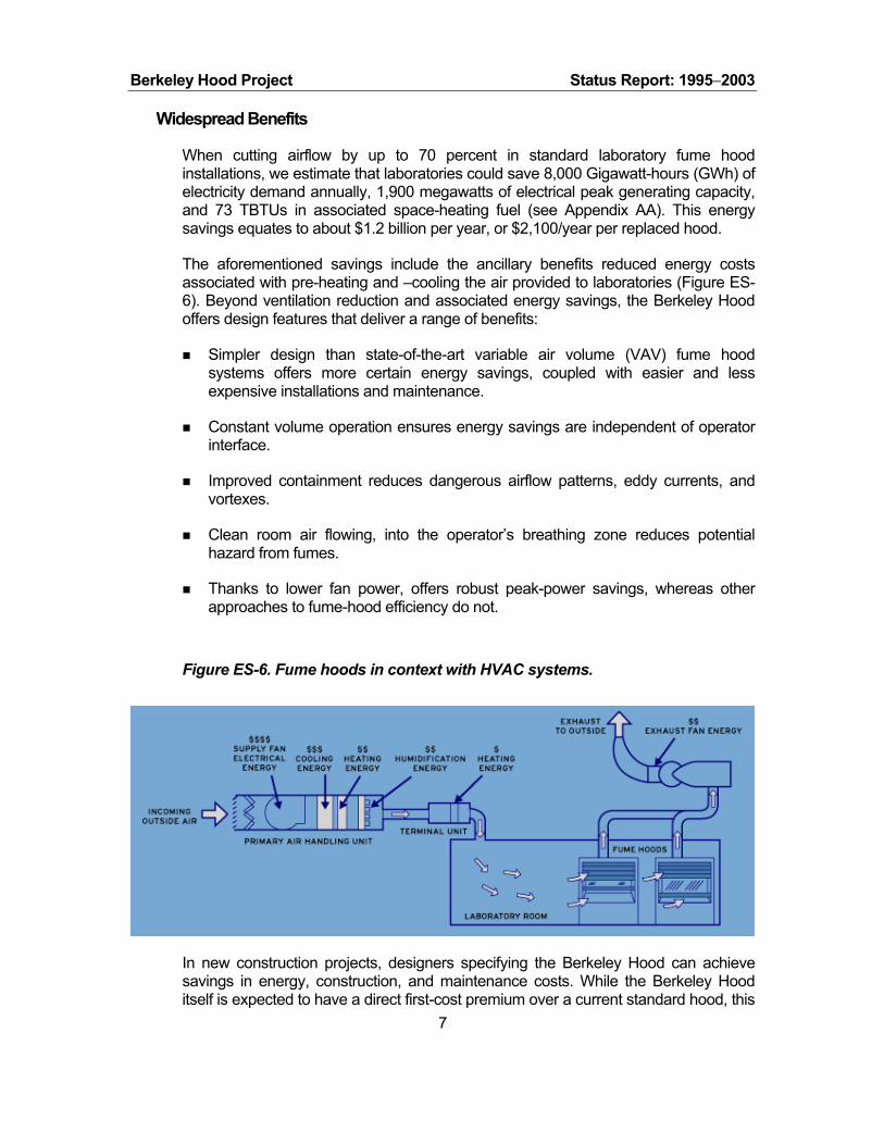
The aforementioned savings include the ancillary benefits reduced energy costs associated with pre-heating and –cooling the air provided to laboratories (Figure ES-6). Beyond ventilation reduction and associated energy savings, the Berkeley Hood offers design features that deliver a range of benefits:
Simpler design than state-of-the-art variable air volume (VAV) fume hood systems offers more certain energy savings, coupled with easier and less expensive installations and maintenance.
Constant volume operation ensures energy savings are independent of operator interface.
Improved containment reduces dangerous airflow patterns, eddy currents, and vortexes.
Clean room air flowing, into the operator’s breathing zone reduces potential hazard from fumes.
Thanks to lower fan power, offers robust peak-power savings, whereas other approaches to fume-hood efficiency do not.
Figure ES-6. Fume hoods in context with HVAC systems.
In new construction projects, designers specifying the Berkeley Hood can achieve savings in energy, construction, and maintenance costs. While the Berkeley Hood itself is expected to have a direct first-cost premium over a current standard hood, this
7

Berkeley Hood Project Status Report: 1995−2003
cost can be offset with first-cost savings from smaller ducts, fans, and central plants, as well as simpler control systems than those used for VAV, offering lower overall first cost than standard or VAV hood systems.
In retrofit projects, Berkeley Hood users can receive critical HVAC system benefits beyond energy savings. Many laboratories are “starved” for air as their need for hoods has grown over the years. As a result, low supply or exhaust airflows cause inadequate exhaust, in some cases, potentially leading to contaminant spills from the hood. Since increasing supply airflow is very costly in most cases, many laboratories cannot add new hoods. By replacing existing hoods with Berkeley Hoods, users can increase the number of hoods or improve exhaust performance, or both. The final result is improved research productivity, enhanced safety, and lower energy bills. A helpful tool for calculating energy savings is provided by Tek-Air Systems, Inc.
Project Timeline
Table ES-3 summarizes highlights of the Berkeley Hood project through June 2002.
Table ES-3. Berkeley Hood development timeline.
1995-98 • LBNL research scientist Helmut Feustel, develops concepts of a Berkeley Hood design
1998 • California Institute for Energy Efficiency funds fume hood research as part of a broad high-tech buildings research program
• Market analysis conducted • Industrial partner identified • Patent application filed
1999 • Project funding from: US DOE (research) and Montana State (field demonstration)
• CFD analysis completed (Two-dimensional) • Containment achieved with “alpha” prototype • Testing and evaluation per ASHRAE 110 begin
2000 • Additional industrial partners join research efforts • Scale-up to larger hoods begins • Patent issued in July 2000; applied for additional patents • PG&E funds field demonstration project • Hood débuts at LABS for the 21st Century in San Francisco • Montana State Univ. demo unit installed September 2000 • PG&E demo unit installed Nov. 2000 at Univ. of Calif. SF • LBNL joins CAL/OSHA hood advisory committee • LBNL joins ASHRAE 110 committee
2001 • SDG&E funds demonstration project • CEC funds field demonstration analysis • Licensing proposal request distributed to partners and industry • Three industry experts brought to LBNL for independent evaluation and
consultation; report • Extensive testing and refinements to air supply distribution
8

Berkeley Hood Project Status Report: 1995−2003
• Licensing request for proposal (RFQ) request distributed to industrial partners and industry; none of the RFQ responses were satisfactory; no license agreement resulted; the technology continues to be available for licensing.
• Extensive work with CAL/OSHA 2002
• Identified new industrial partners (Jamestown Metal Products and Tek-Air
Systems) for fabrication of next-generation (wider, 6-foot sash openings) hoods.
• Second patent awarded • New CEC project initiated; further field testing • Initiated extensive “operational envelope” study to discover range of supply
flows that can maintain containment • Continued work with CAL/OSHA and ASHRAE-110 Committee
2003 (through
September)
• Continued work with CAL/OSHA and ASHRAE-110 Committee • Worked with ANSI and AIHA • Completed initial Envelope Study and Outlet Grill Performance study
Key Accomplishments
The following summarizes key project accomplishments:
Developed the high-performance design concept.
Obtained patents for: the basic concept Energy Efficient Laboratory Fume Hood, (U.S. Patent # 6,089,970, see Appendix Y), using the principal of displacement flow ventilation in a general push-pull configuration; the advanced refinements entitled Low Flow Fume Hood, (U.S. Patent #6,428,408, see Appendix Y) including improved arrangement of supply plenums and interior modifications termed an "air divider.”
Conducted computational fluid dynamic (CFD) analysis to speed design optimization and completed schlieren visualization testing to confirm capture and containment.
Fabricated and tested design alternatives to optimize system performance.
Demonstrated capture and containment following the ASHRAE Standard 110-1995 test, with 70-percent flow reduction compared to standard systems.
Designed alternate lighting systems that reduce lighting energy use by 47 percent, improve lighting quality and reliability while reducing maintenance.
Established partnerships with laboratory hood and controls manufacturers to develop and test alpha units.
Signed intellectual property agreement for product development in the microelectronics field.
Verified performance goals through field tests. 9
Berkeley Hood Project Status Report: 1995−2003
Developed project website and other outreach activities.
Identified industrial demonstration partners with available hood test sites.
Began working with new hood fabricator in 2003.
Compiled specialized Berkeley hood test plan.
Examined commercialization and deployment needs.
Submitted Variance Application to CAL/OSHA to operate Berkeley hood in California; conducted first hearing that resulted in a request for additional support information, i.e., a continuance.
Worked with ANSI/AIHA to identify equivalent performance indicator to a face velocity test; tracer gas testing provides a superior indicator of hood containment performance.
Research & Development Needs
Figure ES-7 provides an overview of progress made to date and the pathway towards completion of the project and commercialization of the product. Although the Berkeley Hood is well on its way to commercialization, numerous hurdles remain to be overcome before facility owners or designers can easily integrate this technology into their projects and before manufacturers will invest in bringing the technology to market. Technology development needs include safety testing and monitoring techniques, creation of additional hood prototypes (e.g. with wider openings), and to define the safe operational envelope and failure modes. Central to this process is continued work on identifying and overcoming institutional barriers, along with field tests and other outreach efforts.
10

Berkeley Hood Project Status Report: 1995−2003
Figure ES-7. LBNL High-Performance Fume Hood Project Timeline: From Theory to Marketplace Note: For a more detailed timeline see Table 5.
Project Supporters
Funding has been provided by the following organizations to address various aspects of the hood's development and testing:
U.S. Department of Energy… Multi-year funding for hood research and development (to develop intellectual property).
California Energy Commission… Provided funding for demonstration project evaluations and to determine future research needs. Will be funding three to four demos for commercial/industrial sector in FY2004.
California Institute for Energy Efficiency (CIEE)… 1998 to 1999 for technology development and technology transfer.
NIST/Montana State University… 1999/2000 funding for the first field demonstration site.
Pacific Gas and Electric Company… 2000 funding for one field test and market transformation activities.
11

Berkeley Hood Project Status Report: 1995−2003
San Diego Gas and Electric Company, through San Diego State University … 2001 funding for one field test and market transformation activities. Providing site for second California demonstration of Berkeley Hood.
The following organizations provided in-kind support:
Jamestown Metal Products… Providing six-foot prototype for next cycle of field demonstrations.
Tek-Air Systems… Providing controls for the next cycle of field demonstrations. Working to promote the hood in the architectural/engineering arena.
Labconco… Provided a fume hoodd superstructure for modification and use in prototype development. Built two prototypes for demonstration installations and field testing.
ATMI… LBNL has partnered with ATMI to develop the Berkeley Hood technology for the microelectronics industry (e.g. wet benches, and equipment cabinets). Entered into an "option to license" agreement for the air divider technology in the microelectronics industry. Developed their own adaptation of the technique for "wet benches" used in semiconductor manufacturing.
Fisher-Hamilton… Provided a six-foot hood for prototype development for larger hoods. Built a four-foot fume hood for field testing at Montana State University.
Fisher-Nickel/PG&E Food Service Technology Center (FSTC)… Collaborated by sharing ideas and methods to visualize airflow in hoods. Used FSTC schlieren device to study Berkeley Hood airflow patterns. LBNL presented at conferences sponsored by FSTC to demonstrate airflow visualization techniques.
Phoenix Controls/Newmatic Engineering... Phoenix engineers evaluated hood's performance with standard ASHRAE 110 protocol and additional challenges, e.g., "walk-by" challenge. Phoenix Controls will provide control package and monitoring interface at SDSU field test site with installation by Newmatic Engineering.
Siemens Building Technologies and Controls… Provided monitoring and control equipment and expertise for one field test.
US Filter/Johnson Screens… Provided protective grill for lower plenum supply at reduced cost; worked with LBNL to design and fabricate special grill; estimated production pricing.
University of California at San Francisco… Provided site and funded installation for the first California demonstration of the Berkeley Hood.
The following organizations served as consultants to the project:
Earl Walls Associates... Will test and evaluate demo installation at SDSU.
12

Berkeley Hood Project Status Report: 1995−2003
Exposure Control Technologies… Provided expert review and evaluation of Berkeley Hood at LBNL.
Knutson Ventilation… Provided expert review and evaluation of Berkeley Hood at LBNL.
Marina Medical Mechanical… Installed the Berkeley Hood at UCSF Medical Center in San Francisco.
SafeLab Corporation… Provided expert review and evaluation of Berkeley Hood at LBNL.
Technology Performance Group… Technical consultant to ATMI during development of semiconductor wet bench system.
Report Overview
This report summarizes the Berkeley Hood project since its inception, focusing on recent achievements and is divided into the following sections:
Background… describing historic development of hood technologies and design criteria
Issues and Opportunities… giving an overview that demonstrates the importance of changing the market to adopt Berkeley Hoods
Project Activities and Accomplishments… summarizing the work completed
Market Development… Patent work, regulatory barriers, field test program, and outreach
Annual Accomplishments… fiscal years 2002 and 2003 highlighted.
Ongoing and Future Activities… describing research and development needs as well as upcoming field tests and prototype fume hoods
References… providing additional details on selected subjects
Appendices… bibliography of cited reports
The Berkeley hood project web site includes additional project information, including detailed supporting documents, videos demonstrating containment, and current/upcoming project activities.
13

Berkeley Hood Project Status Report: 1995−2003
BACKGROUND
Historical Laboratory Fume Hood Development
The earliest fume hoods were used over open fires inside buildings, e.g. at smith’s forges. They provided containment with thermal updrafts in tall chimneys, which resulted from rising air made buoyant by the fire. During the Industrial Revolution, gas-burning rings—used to increased drafts—were replaced by mechanical fans. The next major improvements were the introduction of a five-sided “box” with an operable sash that protected workers by varying the opening size. Later, a baffle system was added at the back of the box. The baffle helped to exhaust air from the hood's working surface area as well as from the top canopy area (Saunders 1993).
In the 1940s, the Atomic Energy Commission asked the Harvard School of Public Health to develop equipment for improving hood operation and safety. As a result, the School improved fume hood entrances to streamline airflow patterns. The advent of High Efficiency Particulate Arrestors (HEPA) filters also resulted from this work. One industry source notes that, despite the claims of hood manufacturers, the basic hood design has changed little over the past 60 years (Saunders 1993).
In today's world, fume hoods are widely used in laboratories and other "high-tech" facilities such as cleanrooms. Varying estimates place the existing stock of fume hoods between 0.5 and 1.5 million. Fume hoods protect operators from breathing harmful fumes by capturing, containing, and exhausting hazardous airborne material created in laboratory experiments or industrial processes. These box-like structures, often mounted at tabletop level, offer users protection with a movable sash that varies the opening size. Exhaust fans draw fumes out the top of each hood by inducing airflow through the front opening, or face, of the fume hood.
Hood airflow face velocity through the sash was originally considered adequate at 50 feet-per-minute (fpm, or 0.25 meters per second, m/s). However, this value increased over time to 150 fpm (0.75 m/s) to "improve" hood safety. Only when a research project, sponsored by the American Society of Heating, Refrigeration, and Air-Conditioning Engineers (ASHRAE), produced a procedure for establishing fume hood performance were face velocities reduced to the range of 60 to 100 fpm (0.3 to 0.5 m/s) (Caplan and Knutson 1978). This research—based on new information relevant to worker safety—formed the basis of ASHRAE Standard 110-1985, a standardized method for evaluating laboratory fume hood performance.
Design Criteria and Conditions for Conventional Laboratory Fume Hoods
General
A conventional fume hood contains hazards by maintaining inward-directed airflow through the face of the hood. The “open face” of a hood corresponds to the area
14

Berkeley Hood Project Status Report: 1995−2003
below the sash at the front of the hood through which air enters (ASHRAE 1995). The size of the open face is variable with the position of the movable sash.
The sources of energy use associated with hoods are depicted in Figure ES-6.
For safe fume hood operation, effective air circulation throughout the laboratory is essential. However, a fundamental goal of energy engineers is to reduce the amount of exhaust air to the lowest safe level because conditioning of make-up air is very energy intensive, in addition to the direct fan energy that can be saved. LBNL’s Laboratory Design Guide (Bell et al. 1996) states that surprisingly few codes stipulate the actual amount of exhaust for laboratory-type facilities.
For laboratories that routinely use hazardous material, the “rule of thumb” of 10 to 12 outside air changes per hour (ACH) is typically used. Bell et al. (1996) recommend an exhaust airflow rate of 1 cfm/ft2 of laboratory floor area (17 m3/h per m2) for occupancy classifications through “H-7.”1 Therefore, for a “B” occupancy laboratory with a ceiling height of 10 ft (3.05m), 1 cfm/ft2 provides six air changes per hour (6 ACH). Often, hoods are the primary exhaust in a laboratory. For example, a fume hood with a face opening of 5 ft by 2.5 ft (1.52 m by 0.76 m) and a face velocity of 100 fpm (0.5 m/s) exhausts 1,250 cfm (2,080 m3/h), which would provide sufficient exhaust for a laboratory space of 1,250 ft2 (116 m2).
Face Velocity
Recommendations for face velocity range from 75 fpm (0.37 m/s) for materials of low toxicity (Class C: TLV > 500 ppm) to 130 fpm (0.65 m/s) for extremely toxic or hazardous materials (Class A: TLV < 10 ppm) (Cooper 1994). Industrial hygienists generally require minimum face velocities of 100 fpm (0.5 m/s) for hoods with open sashes.
However, as shown above, face velocity recommendations have changed over time. In the 1970s, recommendations for face velocity moved from 50 fpm (0.25 m/s) to 150 fpm (0.75 m/s) and higher. Face velocities higher than 125 fpm (0.63 m/s) can create significant turbulence inside and outside the hood, causing fumes to spill into the laboratory (Monsen 1989). The literature reveals there is little relationship between face velocity and containment level (Hitchings 1996; Hitchings and Maupins 1997; Caplan and Knutson 1977; Saunders 1993); many factors are responsible for the effectiveness of a fume hood.
Other Influences On Containment
In addition to the hood design, the position of the worker has a significant influence on airflow patterns in the hood, and particularly in the face of the hood. Airflow around a person’s body standing in front of a hood creates a region of low pressure downstream of the person. This region, which is deficient in air movement (aka
15
1 Group H occupancies include buildings or structures, or portions thereof, that involve the manufacturing, processing, generation or storage of materials that constitute a high fire, explosion, or health hazard.

Berkeley Hood Project Status Report: 1995−2003
“momentum”), is called the wake. A human body disturbs the directed airflow in the face of the hood and can cause contaminants to spill (ACGIH1995).
A hood's overall “box leakage factor” (sash leakage and box leakage) correlates strongly with turbulence intensity. The National Institutes of Health (NIH 1996) and Caplan and Knutson (1978) found that sash leakage is dependent on laboratory airflow patterns. Turbulent fluctuation of air velocity generated outside of the hood in the room can be carried into the hood. This situation can result in spillage from the hood, despite high design face velocities.
Therefore, a hood's performance is affected by its location with respect to doors, supply air outlets, and areas with foot traffic. Saunders (1993) shows that even the highest proposed hood face velocity is smaller than the air velocities created by door openings [175 to 450 fpm (0.83 to 2.25 m/s)] or people passing the hood [260 to 450 fpm (1.30 to 2.25 m/s)]. Even supply air diffusers can create air velocities in the vicinity of the hood that are higher than the hood’s face velocity.
A hood's position in relation to other hoods influences its performance. The National Institutes of Health's study (1996) suggests placing fume hoods on the same wall at least 4 ft (1.22 m) apart, preferably in corners. Hoods on opposite walls perform well, but, according NIH's findings, best performance is achieved when fume hoods are installed on perpendicular walls. In any case, maximizing the distance between two hoods on the one hand and the supply air grille on the other hand provides the best performance. For more details about laboratory design, see Bell et al. (1996).
Construction Details Of Conventional Fume Hoods
The size of a fume hood is described in terms of its outside dimensions. The width of the interior work chamber is found by subtracting the thickness of the two sidewalls from the total width. Therefore, a 6 ft (1.83 m) fume hood with side walls of about 6 inches (0.15 m) each has an interior work chamber width of 5 ft (1.52 m). The sidewalls have considerable width because they contain mechanical and electrical services. Typical hoods have aerodynamically-shaped sidewalls.
The most important aerodynamic design feature of a standard fume hood is an entrance airfoil. This airfoil helps prevent formation of turbulent airflow at the front edge of the hood's working area. The depth of the work space depends on the design of the hood's air foil and the back baffle (Saunders 1993). This leaves a work area that is approximately 21 inches (0.53 m) deep. The dimensions of the work space within the fume hood should be determined by the worker's needs. Using a hood that is larger than needed triggers unnecessary initial costs, energy, and other operating costs (Cooper 1994). However, deeper hoods offer superior containment. In sum, overall hood depth, including the thickness of an outside shell, varies from 32 to 37 inches (0.81 to 0.94 m).
Airflow in an optimum hood design “sweeps” the work area without forming vortexes (Figure 1) inside the hood. Uncontrolled vortexes within a hood can cause spillage of contaminants into the laboratory. Typical locations for a vortex to form are: (1) above the open sash, which spills through the hood's face and (2) near the work surface. If
16
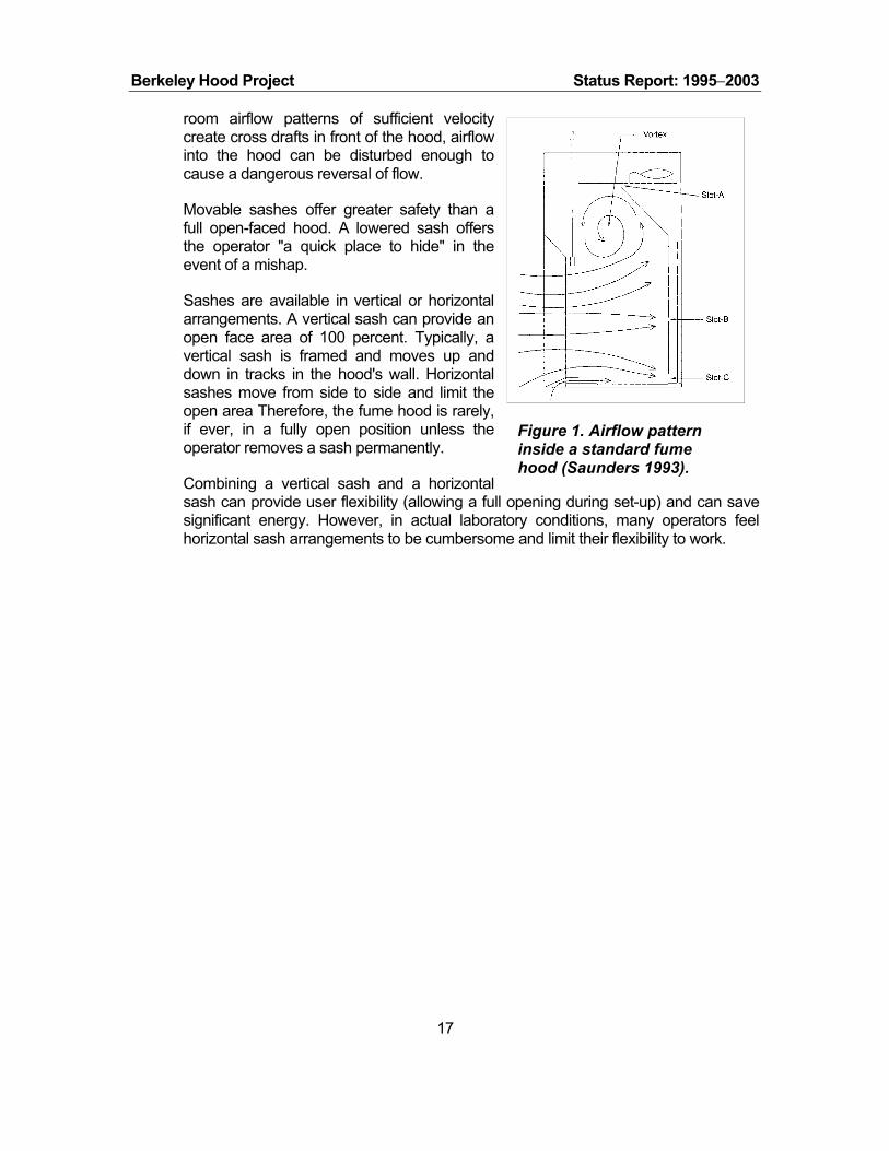
Berkeley Hood Project Status Report: 1995−2003
room airflow patterns of sufficient velocity create cross drafts in front of the hood, airflow into the hood can be disturbed enough to cause a dangerous reversal of flow.
Movable sashes offer greater safety than a full open-faced hood. A lowered sash offers the operator "a quick place to hide" in the event of a mishap.
Sashes are available in vertical or horizontal arrangements. A vertical sash can provide an open face area of 100 percent. Typically, a vertical sash is framed and moves up and down in tracks in the hood's wall. Horizontal sashes move from side to side and limit the open area Therefore, the fume hood is rarely, if ever, in a fully open position unless the operator removes a sash permanently.
Figure 1. Airflow pattern inside a standard fume hood (Saunders 1993).
Combining a vertical sash and a horizontal sash can provide user flexibility (allowing a full opening during set-up) and can save significant energy. However, in actual laboratory conditions, many operators feel horizontal sash arrangements to be cumbersome and limit their flexibility to work.
17

Berkeley Hood Project Status Report: 1995−2003
ISSUES AND OPPORTUNITIES
Current Technology
Standard Designs Dictate High Exhaust Rates
Standard fume hood design (Figure 2) is based on airflows of 100 feet per minute and the assumption that the sash is fully open. Therefore a hood with a standard nominal 6-foot opening requires an exhaust rate of 1250 cubic-feet-per-minute.
As previously described, and contrary to common expectations, increasing face velocity does not improve containment. Instead, errant eddy currents and vortexes are induced around hood users as airflows into the hood, reducing containment effectiveness.
Laboratory fume hoods are operated 24 hours/day. Since many laboratories have multiple hoods, they typically dictate a lab’s overall required airflow and thus the entire facility’s supply and exhaust system capacity (and thus cost). The result is larger fans, chillers, boilers and ducts compared to systems having less exhaust. Consequently, fume hoods are a major factor in making a typical laboratory four- to five-times more energy intensive than a typical commercial space.
Figure 2. Standard laboratory hood in use.
Currently Available Energy-Efficient Systems Face Limitations
In the past, four design strategies have been used to reduce fume hood energy use.
• Using “auxiliary” (outside) air to reduce energy required by a central HVAC system that conditions the air ultimately exhausted by the hood.
This strategy, referred to as an auxiliary-air hood, introduces outdoor air near the face of the hood just above the worker. Un-conditioned air introduced by auxiliary-air hood systems causes uncomfortable conditions for workers during periods of summer and winter temperature or humidity extremes. The auxiliary airflow can interfere, in various ways, with experiments performed inside the hood. More importantly, turbulence, caused by inflowing auxiliary air at the hood opening, increases the potential for pollutants to spill from the hood towards the worker (Coggan 1997; Feustel et al. 2001). Moreover, auxiliary air hoods only save energy used for conditioning general laboratory air. This is the case because total exhaust flow rate is unchanged. A hood’s fan energy consumption is not reduced and may even be increased by the necessity of an auxiliary supply fan. Our estimates indicate that as much as 65
18

Berkeley Hood Project Status Report: 1995−2003
percent of hood energy is attributable to the fans (moving air) with the balance attributable to conditioning the air.
• Employing dampers and adjusting fan speed to reduce exhaust airflow through the hood as the sash is closed. This variable air volume (VAV) approach maintains a constant face velocity, enhancing the hood's ability to contain fumes.
This strategy uses dampers, variable speed drives (VSDs), and sophisticated controls to modulate the hood and in the supply and exhaust air streams. These components communicate with direct digital controls (DDC) to provide a variable air volume (VAV) fume hood system. A VAV system establishes a constant face velocity. VAV improves safety, compared to standard hoods, which experience variable face velocity as the face opening is adjusted. Additional controls maintain a constant pressure differential between the laboratory and adjacent spaces. These components and controls add significantly to the system’s first cost and complexity and require diligent users. Each hood user must close the sash properly to ensure that the system achieves its full energy savings potential. Also, when sizing air distribution and conditioning equipment, many designers assume worst-case conditionsall sashes fully openrequiring larger ducts, fans, and central plants than would be the case if some sashes are assumed to be partly closed.2
• Restricting sash openings by preventing the sash from being fully opened, or using horizontal-sliding sashes that cover part of the hood entryway even when in the “open” position.
This strategy restricts a hood’s face opening while maintaining airflow velocity. The face opening is restricted by “stops” limiting vertical sash movement or by using a horizontal sash system that blocks part of the entrance, even when fully open. Stops or sashes are routinely removed by users to facilitate “set-up” of experiments. During set-up, the face velocity is lowered, often significantly, and containment reduced. Users often do not like these restrictions, so it is common to see hoods under normal use with their stops bypassed or the horizontal sashes removed. In these cases, the air velocity drops below specified levels and compromises safety.
• Automated designs that promote a vortex in the top of the fume hood, which is maintained by "sensing" whether it is collapsing, or not, and adjusting movable panels in the top of the hood accordingly.
This strategy has been effectively applied to fume hood design, although it is not entirely accepted or understood by laboratory designers. This hood design incorporates, according to the manufacturer, a "bi-stable vortex" to enhance its containment performance. The design promotes a vortex in the top of the fume hood,
19
2 Based on the assumption that not all hoods are used simultaneously in a VAV fume hood system, applying a “hood diversity factor” in calculating the building’s make-up air has also been suggested as an HVAC energy-saving measure (Moyer and Dungan 1987; Varley 1993).

Berkeley Hood Project Status Report: 1995−2003
and maintains this vortex by "sensing" whether it is collapsing, or not, and adjusts movable panels in the top of the hood accordingly.
While the aforementioned strategies can result in energy savings, they fall short of the full potential. Given the rising importance of electricity reliability and load management, it is also worth noting that these strategies may not diminish peak-power requirements.
Opportunity For Improvement
A New Approach to Containment and Safety – The Berkeley Hood
Conventional hoods (and the above-mentioned energy efficiency strategies) rely on pulling supply air from the general laboratory space around the worker and research apparatus that may be located in the hood. Safety performance is susceptible to everyday activities in the lab, movement of people, opening and closing of doors, central air supply fluctuations, etc. Past efforts have not looked at the potential for re-conceptualizing and redesigning the hood to maintain or improve worker safety with lower airflows.
A new strategy for managing fume hood energy, the Berkeley Hood technique supplies air in front of the operator, while drawing only about 10 to 30 percent of the air from around the operator.3 As a result, far lower flow-rates are necessary in order to contain pollutants and flow-rates remain virtually unaffected by adjustments to the sash opening. This supplied air creates a protective layer of fresh air free of contaminants. Even temporary mixing between air in the face of the fume hood and room air, which could result from pressure fluctuations in the laboratory, will keep contaminants contained within the hood.
The Berkeley Hood uses a "push-pull" displacement airflow approach to contain fumes and move air through a hood. Displacement air “push” is introduced with supply vents near the top and bottom of the hood’s sash opening. Displacement air “pull” is provided by simultaneously exhausting air from the back and top of the hood. The low-velocity supply airflows create an “air divider” between an operator and a hood’s contents that separates and distributes airflow at the sash opening (unlike an air curtain approach that uses high-velocity airflow). When the face of a hood is protected by an airflow with low turbulent intensity, the need to exhaust large amounts of air from the hood is largely reduced. The air divider technology contains fumes simply, protects the operator, and delivers dramatic cost reductions in a facility’s construction and operation.
The Berkeley Hood must not be confused with the auxiliary air approach. There are fundamental and material differences, stemming from the fact that the Berkeley Hood does not utilize outside air, and that air is introduced from within the sash in a highly controlled fashion with far lower turbulence (and thus lower risk of contaminant
20
3 This generic concept was first tested in the “air vest” technology, invented at LBNL for use with large paint spray hoods (Gadgil et al. 1992) The vest supplies air in front of the operator of the hood, which creates a positive pressure field that prevents development of a wake, therefore ensuring clean air to the operator’s breathing zone.

Berkeley Hood Project Status Report: 1995−2003
spillage) than occurs with auxiliary hoods. In auxiliary-air hoods, turbulent airflows coming from above the worker in auxiliary-air systems increase mixing of incoming fresh air and contaminated air within a hood’s workspace.
An added attraction of the Berkeley Hood installation is that its incremental cost is expected to be less than that of VAV systems. Savings from downsized heating, ventilating, and air conditioning systems and less complicated controls would also be realized.
The Berkeley Hood project also included hood lighting systems. Newly designed components cut lighting energy nearly in half while improving control, quality and reliability.
Initial Groundwork
LBNL developed basic concepts for a high-performance laboratory fume hood during 1995−1998 (Feustel et al. 2001).4 This early work included a number of activities, (see Appendix G, Energy Efficient Fume Hoods) including:
Establishing proof of concept by fabricating and testing hood mock-ups.
Conducting simple, two-dimensional computational fluid dynamic (CFD) analysis to determine airflow patterns in standard hood configurations.
Presenting preliminary results to industry groups and soliciting support.
Publishing findings.
Obtaining patents.
Market Analysis
The project team conducted a preliminary market analysis to identify market size, potential energy savings (Table 1), and potential market impact (see Appendix F). Our calculations account for the heating, cooling, and movement of fume hood air.
The results suggest the following:
Approximately 150,000 laboratories populate the United States, with 500,000 to 1,000,000 total fume hoods installed. This range is based in part on interviews of industry experts conducted on behalf of the Labs21 project, and excludes an “outlier” estimate of 1.5 million. The only formally published estimate indicated that there were more than 1 million units in 1989 (Monsen 1989). Our calculations assume a “central value” of 750,000.
21
4 Dr. Feustel left LBNL in January 1999. At that time, LBNL's Environmental Energy Technologies Division (EETD) transferred the project to its Applications Team, with Dale Sartor, P.E. as Principal Investigator and Geoffrey C. Bell, P.E. as Project Head. Dr. Feustel remains a consultant to the project.

Berkeley Hood Project Status Report: 1995−2003
Each new five-foot hood will save about 3.4 kW and 14,200 kWh/year.
We assumed that approximately 75 percent of all existing hoods could be replaced with the Berkeley Hood, with energy savings of 50% per hood. Based on 750,000 hoods, this corresponds to total annual U.S. electricity savings of 8,000 GWh and 1,900 megawatts of electrical generating capacity. Inclusion of (de)humidification and exhaust “scrubbing” used in some hoods would increase the total energy savings.
It is important to note that laboratory ventilation is based on 100 percent outside air (see Figure ES-6). All the air exhausted by a fume hood has to be made up with outside air. Unfortunately, many labs use "reheat." Typically, the outdoor air is initially cooled to 55 degrees Fahrenheit (F) (or even lower if the internal load requires) to remove unwanted humidity and then reheated to the required temperature to maintain the laboratory’s set point temperature. Unfortunately, it is possible for only one laboratory to actually need maximum cooling. If the outside air is cooler than the supply air set-point (say 55 degrees) then no cooling is required. But, for example, the outside air can be a “perfect” 65 degrees. In this situation, it is first cooled at the central air handlers and then re-heated back to 65 degrees at each zone. The perverse result of this “reheat” practice is that in many labs the dominant cooling load is the boiler and the dominant heating load is the chiller. Labs can be designed much better than this, but many are worse than the assumptions used in our calculations. Improving lab energy design is a significant, under-served market opportunity.
Further work is required to refine the engineering assumptions as well as the data on stock characteristics. Existing estimates of hood populations vary widely. The energy performance and savings potential of fume hoods is highly dependent on regional weather conditions, baseline HVAC system efficiencies, and market penetration of substitute technologies. The current analysis has not included the added energy costs of dehumidification.
Research Efforts Expand
Based on early findings and successes, the project team developed a research plan with a comprehensive approach for developing the Berkeley Hood. The project worked with the California Institute for Energy Efficiency (CIEE) to verify the performance of the technique. The hood’s ability to contain hazardous fumes was checked by an outside consultant by performing tests per a standardized protocol (ASHRAE 110, described below). This rudimentary prototype passed the containment tests, proving the merit of the technique (Feustel et al. 2001). Early CIEE funding was augmented with support from the DOE and Montana State University (MSU). This support, and the test results, encouraged Labconco to provide “in-kind” support by donating a four-foot-wide hood to the project. This combined support allowed research to expand significantly. The project subsequently increased research with new, innovative airflow visualization methods.
22

Berkeley Hood Project Status Report: 1995−2003
Table 1. Analysis of fume hood national energy savings potential. System Assumptions
Hoods use 100% outside air, 24/7/365 operation; constant-volume systemHood Flow (six-foot nominal opening) 1250 CFMCombined fan power (supply/exhaust) [2] 1.8 W/CFM Kjelgaard assumes 0.9W/CFM for supply only)Cooling plant efficiency [1] 1 kW/ton Kjelgaard assumes a range of 0.45 to 1.4 Heating system efficiency 70% for a range of cooling plant typesReheat Energy (assume average delta-T is 10F: 55->65F) 94,608 BTU/year-CFM
Outside air is cooled or heated to 55deg. F supply temperature = (0.018 BTU)(10deg F)(60min)(24h)(365days)Air is reheated at each zone for temperature control; Conservatism: humidification energy not included in this analysis
State UnitedCity StatesElectricity Price: avg. of com'l and ind'l tariff ($/kWh) 0.065Electricity Demand Charge ($/kW-year) 120Natural Gas Price ($/MBTU) 6.29
Cooling ElectricityCooling ton-hours/CFM (55deg supply) [1] 7.00Chiller energy (kWh/year) 8,750 Fan energy (kWh/year) 19,710 Total Energy (kWh/year) 28,460 Total Power (kW/hood) Fan 2.3 Chiller 4.5 Total 6.8 Electricity Cost
Electricity ($/year) 1,850 Demand ($/year) 810 Total ($/year) 2,660
Heating EnergySupply Heating Energy (Therms/CFM) [1] 0.50Supply at 55 deg. F (BTU) 62,500,000 Reheat 10 deg (55 to 65F) (BTU) 118,260,000 Total (BTU) 180,760,000 Energy (BTU) 258,228,571 Heating Cost ($/year) 1,625
Total Per-Hood Energy Cost ($/year) 4,285
MACRO-SCALE ENERGY USE
Number of Hoods 750,000 Total Electricity (GWh/year) 21,345 Total Peak Power (MW) 5,063
Total Natural Gas (Trillion BTUs/year) 194 Total Energy Cost ($ Million/year) 3,214
MACRO-SCALE ENERGY SAVINGSPer-hood energy savings 50%Maximum potential market penetration 75%
Electricity ($M/year) 520Demand ($M/year) 228
Natural Gas ($M/year) 457
Total Energy Savings ($ Million/year) 1,205 Total Electricity Savings (GWh/year) 8,004 Total peak power savings (MW) 1,898 Total heating fuel savings (TBTU) 73
Comparision to typical house US Avg Hood US Avg HouseHood/House
Ratio $/year 4,285 1,338 3.2 Electricity/year (kWh) 28,460 10,217 2.8 Fuel (MBTU) 258 Total Site Energy (MBTU) 355 101 3.5Sources:
1. Kjelgaard, J.M. 2001. Engineering Weather Data. McGraw-Hill. ISBN 0-07-137029-32. Weale, J., D. Sartor, and E.L. Lee. 2001. "How Low can Your Go? Low Pressure Drop Laboratory Design.3. Energy Prices: (average electricity cost $/kWh: average of industrial and commercial tariffs). Demand charges are LBNL estimates.
elect http://www.eia.doe.gov/cneaf/electricity/epm/epmt53p1.htmlgas http://www.eia.doe.gov/oil_gas/natural_gas/info_glance/sector.html
23

Berkeley Hood Project Status Report: 1995−2003
Fisher-Hamilton also became interested in the project and provided support at several levels), including providing a six-foot-wide hood for scaling-up the technique for application in the next larger size hood more typically used in laboratories. Further field demonstrations have been conducted. A greater understanding of the technique was gained from this research, new intellectual property was identified, and the hood design refined. In parallel with technology development, LBNL participates in critical codes and standards activities conducted by ASHRAE and CAL/OSHA.
Institutional Barriers
In conjunction with identifying design improvements and market opportunities, the project team pinpointed market barriers to adopting the new hood technology (Vogel 1999). Their research uncovered hurdles to widespread adoption.
The ASHRAE Standard 110-1995 is the most widely used test method for evaluating a hood’s containment performance. This method recommends three types of tests but does not stipulate performance values that need to be attained by a fume hood. Aside from the full ASHRAE method, the most commonly used indicator of hood capture and containment is hood face velocity, which is only one part of the ASHRAE Standard. A commonly accepted value of 100 feet/minute (fpm) is widely applied. While this value has limited technical merit, it presents the most significant barrier to widespread adoption of the Berkeley Hood. Hoods using LBNL’s low-flow technique provide containment of tracer gas and smoke per the other ASHRAE 110 tests. With the internal supply fans off, the Berkeley hood is operated an “equivalent” face velocity of approximately 30 to 50 FPM. The actual velocity is much less as most of the air is introduced at the face in directions that are not “normal” (perpendicular) to the plane of the hood’s sash.
In California, CAL/OSHA requires 100 fpm face velocity for a laboratory fume hood (non-carcinogen) to be in compliance, limiting the use of the Berkeley Hood in California and potentially in other States that follow California’s lead.
Other similar barriers can be found in a variety of standards. For example, the EPA promulgates a standard used in their procurement procedures but is also adopted for use by others. The requirement for 100 fpm face velocity is deeply ingrained through this industry and is a major market barrier to push-pull hoods.
PROJECT ACTIVITIES AND ACCOMPLISHMENTS
This section summarizes project activities and accomplishments, with the information split into three categories: (1) project administration planning; (2) technology development and field testing; and (3) market development.
Project Administration
The Berkeley Hood project is a multi-year, multi-phase research and technology development project effort. It has been widely supported, by public and private
24

Berkeley Hood Project Status Report: 1995−2003
organizations alike, and has leveraged expertise within a number of groups within LBNL.
Project Supporters
Initial work was supported by LBNL’s Environmental Energy Technologies Division. In 1998, the California Institute for Energy Efficiency (CIEE) began funding the hood research as part of a multi-year, multi-phase research project in the high-tech building area. The early scoping research on the topic was performed by LBNL (Mills et al. 1996). Additionally, the U.S. Department of Energy (DOE) and Montana State University funded basic research and prototype development from 1999 through 2001. A full list of project sponsors and in-kind contributions is provided in the Executive Summary.
Project Plan Established
Project activities increased in 1999 with the additional sponsorship noted above. The team developed an extensive work plan to develop the technology, establishing key goals (See Appendix A). To adequately structure these goals, 26 work elements were identified. From these work elements, the team then created the following eleven Tasks:
Analyze Airflow And Containment
Characterize Screen Airflow
Design Supply-Air Plenums
Design Rear Baffle System
Construct, Install, And Startup A Prototype Hood
Ensure Hood Operational Safety
Perform Hood Tests
Secure Patent
Transform Regulatory Barriers
Implement Hood Demonstration Program
Develop Outreach Activities
25

Berkeley Hood Project Status Report: 1995−2003
Project Team
The project team leveraged expertise throughout LBNL’s Environmental Energy Technologies Division (EETD). A team of student researchers greatly aided their efforts, particularly in fabricating and testing alternative hood features.
Summer Student Contributions Soliciting candidates from The U.S. Department of Energy’s Energy Research Undergraduate Laboratory Fellowship (ERULF) and Community College Initiative (CCI) Student Mentor Programs, LBNL hires students from various engineering disciplines from universities around the nation and abroad.
Once on board, each student performs research on the fume hood technology and analyzes data. The students have made significant accomplishments by developing components and features for the prototype hood (Roberts 1999, Appendix H; Chan 1999, see Appendix K; Griffin 1999, see Appendix J; Vogel 1999, see Appendix I; Fox 2000, see Appendix L; Homer 2000, see Appendix Q; Huang 2000, see Appendix R; Fisher 2001, see Appendix S; Guthrie 2001, see Appendix T; Matthes 2002, see Appendix P; Soule 2002, see Appendix O; Suda-Ciderquist 2003, see Appendix U).
LBNL’s experience with the DOE program was quite positive and the project was decidedly enriched by each student’s commitment. Keys to their successful involvement included the following:
Feeling a common sense of purpose
Sharing information and problems at regular meetings
Knowing that their input was relevant
Seeing tangible and demonstrable results
Having involvement at all levels of the process, including hood demonstrations to outside professionals
Technology Development
Analyze Airflow and Containment
Examine Airflows Initial progress with Computational Fluid Dynamics (CFD) modeling suggests that this is a powerful tool with considerable untapped potential. By expanding from two-dimensional (2-D) to three-dimensional (3-D) models, airflow from the lab space into, and through, the hood would be analyzed. 3-D models enable research to take into account influences of a person working in front of the Berkeley hood. These influences include impacts of an operator's height, position, and relative size on airflow turbulence. With a 3-D CFD model, the hood’s safety performance at various
26

Berkeley Hood Project Status Report: 1995−2003
breathing-zone heights could be evaluated. 3-D CFD models could be used to further optimize an array of hood features ranging from geometry to air distribution approaches. A sample of a 3-D model run, by ADAPCO’s StarCD program, is presented in Figure 3. In this run, an iso-surface of SF6 tracer gas concentration is shown. One can readily observe that the Berkeley hood completely contains the tracer gas.
Figure 3: Computational Fluid Dynamic (CFD) evaluation of Berkeley hood containment of SF6 tracer gas ejected at 4 liters per minute from idealized 6 inch wide by 30 inch tall ejector surface. Operator breathing zone is at 26 inches above work surface. Iso-surface concentrations indicate complete containment of tracer gas.
27
Berkeley Hood Project Status Report: 1995−2003
In addition to CFD analysis, the team applied several other types of flow visualization techniques to qualitatively understand airflow into and through the prototype hood. The techniques included the following:
Smoke; small volume - Very stable “point source” smoke can be provided with smoke “sticks” using titanium tetrachloride. These sticks were used after any design change or rearrangement to quickly determine how air was moving within the hood.
Smoke; large volume - Theatrical smoke machines generate large quantities using superheated glycols. Smoke was released inside the hood and into each supply fan inlet to observe supply plenum effect.
Bubbles - A device using helium gas to blow bubbles with a specially formulated detergent was used. The resultant bubbles are neutrally buoyant and provide a unique method to observe all types of airflow in the hood’s interior.
Schlieren Effect – We employed a schlieren flow analysis methods to visualize air at different densities. The team borrowed a schlieren visualization unit from PG&E’s Food Service Technology Center, which enabled us to record very small amounts of smoke moving through the hood. Observations were performed, varying one of several variables at a time, and a digital archive of the results was established. Funding limitations have hindered further analysis of the schlieren results that could lead to hood design improvements.
Computational Fluid Dynamic (CFD) Modeling – Two-Dimensional (2-D)
LBNL researchers conducted over 30 Fluent Computational Fluid Dynamic (CFD) runs to model airflow through the hood. Examples comparing the Berkeley Hood to a standard hood are shown in Figure 4. The series of simulations studied numerous airflow arrangements and criteria, including:
Total supply volume versus total exhaust; Total exhaust only
Volume of each of four supply inputs
Eliminating one or two supply air inputs
Relative intensity of airflow vectors and streamline boundaries
Flow from the room into the hood
Induced vortexes inside of the hood
Flow near and through back baffle slots
28

Berkeley Hood Project Status Report: 1995−2003
Figure 4. Computed fluid dynamics (CFD) airflow simulations. In these simulations, color contours show streamlines; flow rates are higher where the distance between streamlines is small. In the standard hood (left), all airflow drawn through the sash opening is exhausted. Closed loops indicate zones of recirculating air (blue – clockwise; red – counterclockwise) and potential contaminant spill. The Berkeley Hood (right), introduces 70 percent of total exhaust flow vertically at the sash in front of the operator with low-turbulence intensity. The recirculating loops (right graphic) have been eliminated in subsequent design improvements to the Berkeley Hood. Consequently, the Berkeley Hood can be operated at 75% less airflow than the standard hood.
Standard Hood
Horizontal supply-airflow from lab space.
Berkeley Hood
Vertical flow from top and bottom of sash.
ee
e
Sash Opening
100 feet per minut
Results High turbulence in hood sash area (entrance);
pollutants more likely to spill out of hood.
29
60 feet per minut
70 feet per minut
Results Low turbulence in sash area and both vortices reduced and moved away from opening.
Berkeley Hood Project Status Report: 1995−2003
Researchers completed modeling on both a generic design and an actual fume hood superstructure. Initial CFD runs were computed prior to LBNL obtaining an actual fume hood superstructure from our industrial partner. Therefore, geometric relationships were generalized with respect to sash size, interior dimensions, back-baffle arrangement, etc. These runs varied airflow quantities for all three supply plenums and overall exhaust quantity.
Our first industrial partner, Labconco, provided a fume hood superstructure and its dimensions were transferred into the CFD model. We included an advanced shape for the lower, inside plenum surface. It is curved with a constant radius; however, the model uses a simple combination of a vertical and horizontal surface to approximate the curved surface.
Observations and interpretations of the CFD modeling yielded the following critical findings:
All four supply air inputs (two upper plenums and a vertical and horizontal surface of the lower plenum) are necessary;
Total supply air through the sash grilles should not exceed 80 percent of total exhaust volume;
Horizontal flow from lower plenum supply was not producing the expected results;
A strong vortex in the bottom of the hood at the working surface was being generated. This vortex spun horizontally such that air in its lowest portion was directed towards the hood’s sash. Inside this vortex was a zone of “no flow,” a situation both undesirable and potentially dangerous; and
Another strong vortex was also being generated in the top of the hood near the sash (this is the most typical region to spill and fail on standard hood designs). This vortex spun horizontally so that air in its upper portion was directed towards the hood’s sash. Inside this vortex was a zone of “no flow,” a situation both undesirable and potentially dangerous.
Analyze Interior Vortex The potentially dangerous interior vortexes, noted in the CFD runs and shown in Figure 4, are also found in standard hood configurations. To eliminate, or reduce, induced vortices generated in the bottom and top of the fume hood, approximately twenty back baffle arrangements were modeled. From the CFD runs, it was observed that the back baffle has a strong role in forming the upper and lower vortices. However, none of the back-baffle arrangements modeled eliminated these vortices. To confirm results predicted by the CFD models, various back baffle configurations were built and checked by empirical observation. The CFD model results were validated.
Although the CFD computer runs by themselves did not lead directly to a design that fully contained the flow or eliminated the vortices, the models were helpful in increasing the team’s understanding of airflow problems within the hood. The results
30

Berkeley Hood Project Status Report: 1995−2003
were ultimately positive, and the CFD runs helped achieve a physical solution to eliminating the vortices.
Characterize Screen Airflow
Background A laminar supply-airflow is desirable. It was known that a mesh screen placed across an airflow (e.g. in a fume hood) will have an evening effect, distributing both the velocity and pressure across the screen. However, this effect had not been quantified and the effect of differing mesh geometry was unknown. It was desired to understand the relationship between airflow velocity, the pressure behind the screen and the free hole area of the screen. We concluded that pressure is proportional to the velocity for a given free hole area, and inversely proportional to free hole area for a given velocity. Screens with less free hole area also maintain laminar flow on exit for a greater distance. Testing addressed two issues: (1) the relationship between airflow velocity and pressure, and (2) the distance laminar flow exists after leaving the plenum.
The tests were performed on a test apparatus constructed from acrylic tubing. This transparent construction allowed easy observation of flow patterns within the device. It consisted of an orifice-plate for flow measurement, an axial flow fan, several sections of honeycomb for flow straightening, and the screen holder (Figure 5). Measurements were taken from two pressure taps situated at either end inside the orifice plate and screen holder.
Figure 5. Screen test rig.
Before it could be used for experiments, the test apparatus was calibrated to obtain a relationship between the orifice pressure and the flow velocity since a pressure meter is more convenient than an anemometer. The pressure meter can provide time averaged results, whereas the anemometer gives instantaneous (and often wildly fluctuating) results. To calibrate the apparatus, a series of velocity/pressure readings were taken and graphed, obtaining a fitted curve and equation.
The curves and equations were obtained by regression analysis, fitting the points to a power law relation (y=axb). They generally fit the test results quite well. Some insignificant deviation is evident on certain screen runs. Qualitatively it is possible to conclude that increasing the free hole area of a screen decreases the back pressure. This is consistent for all screens tested.
31

Berkeley Hood Project Status Report: 1995−2003
First Set of Tests Once the testing was calibrated, it was possible to run the actual tests on the screens. Each screen in turn was placed between the two front plates and measurements were taken at the orifice plate and just behind the screen for the fan’s entire velocity range. In addition to taking the numerical measurements, smoke was blown through the system and its exit behavior observed.
Second Set of Tests The second set of tests involved measuring the laminar distance of the flow upon exita difficult process since room air currents could easily disturb the flow and cause inexact results. Although the flow results were too erratic to attempt to draw any mathematical relation, clearly, a smaller free hole area causes the flow to remain laminar for a greater distance. It is unknown how this length will scale for different exit geometries, and since the length is quite small (less than 3 inches), it is unlikely this property will have relevance on a larger scale.
Photos of the laminar flow after existing a screen illustrate a series of vortices developing at the edges of the flow (Figure 5, above). Although the vortices were unclear in the two-dimensional images, they appear to mimic a Karman Vortex Street5 in three dimensions. These vortices seem to be the mechanism by which the flow disperses and spreads out.
A numerical relation was obtained for screen pressure, velocity, and free hole area that confirmed the expected results. The relation between free hole area and laminar distance was a new discovery and raises many questions about the geometric exit effects. Additionally, comparing the test results with and without the screen clearly demonstrates that a screen causes the flow to remain collimated for a much greater distance before it disperses.
Since each fume hood application has unique needs for a screen, this experiment provides a method of determining required fan capacity when using screens (Roberts 1999).
Design Supply Air Plenums
Overview Ideally, air flowing out of all supply plenums should be of equal velocity over its entire surface. Further, this airflow should remain laminar for the greatest distance possible into the hood to help move air and fumes towards the hood’s outlet. In designing the plenums the researchers sought to achieve uniform air velocity across the entire plenum surface. Further, they sought to have laminar airflow for the greatest distance possible into the hood to help move air and fumes towards the hood’s outlet. To improve viewing of the airflow in the bench-test unit the team constructed the
32
5 This is the term a fluid dynamics boundary theory. The phenomenon is observed when flow is initiated around a cylinder. The process is initiated when "vorticies break away alternately from the cylinder an move downstream..." "The arrangement of these vorticies in the wake is called a Karman vortex street" (Shames 1962).
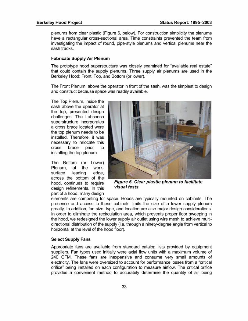
Berkeley Hood Project Status Report: 1995−2003
plenums from clear plastic (Figure 6, below). For construction simplicity the plenums have a rectangular cross-sectional area. Time constraints prevented the team from investigating the impact of round, pipe-style plenums and vertical plenums near the sash tracks.
Fabricate Supply Air Plenum The prototype hood superstructure was closely examined for “available real estate” that could contain the supply plenums. Three supply air plenums are used in the Berkeley Hood: Front, Top, and Bottom (or lower).
The Front Plenum, above the operator in front of the sash, was the simplest to design and construct because space was readily available.
The Top Plenum, inside the sash above the operator at the top, presented design challenges. The Labconco superstructure incorporates a cross brace located were the top plenum needs to be installed. Therefore, it was necessary to relocate this cross brace prior to installing the top plenum.
The Bottom (or Lower) Plenum, at the work-surface leading edge, across the bottom of the hood, continues to require design refinements. In this part of a hood, many design elements are competing for space. Hoods are typically mounted on cabinets. The presence and access to these cabinets limits the size of a lower supply plenum greatly. In addition, fan size, type, and location are also major design considerations. In order to eliminate the recirculation area, which prevents proper floor sweeping in the hood, we redesigned the lower supply air outlet using wire mesh to achieve multi-directional distribution of the supply (i.e. through a ninety-degree angle from vertical to horizontal at the level of the hood floor).
Figure 6. Clear plastic plenum to facilitate visual tests
Select Supply Fans Appropriate fans are available from standard catalog lists provided by equipment suppliers. Fan types used initially were axial flow units with a maximum volume of 240 CFM. These fans are inexpensive and consume very small amounts of electricity. The fans were oversized to account for performance losses from a “critical orifice” being installed on each configuration to measure airflow. The critical orifice provides a convenient method to accurately determine the quantity of air being
33
Berkeley Hood Project Status Report: 1995−2003
provided. All supply fans are variable speed controlled with a nearly infinite turn-down ratio. Centrifugal fans were also studied.
Fan Location
An axial supply fan’s rotating blades tend to spin, or “swirl”, air it is flowing. Swirling air causes erratic flow out of a plenum. Correctly locating a fan in a plenum correctly mitigates swirl caused by an axial fan. Numerous approaches were tried to eliminate swirl, and other flow problems, caused by this type of supply fan. A costly but effective approach uses aluminum honeycomb material as a “straightener” to defeat swirl. Alternatively, when a fan can be located a sufficient distance from the plenum’s outlet, swirl can be eliminated by forcing a fan’s airflow through one ninety-degree turn.
Airflow Profiles
We evaluated airflow distribution from each supply plenum’s outlet surface. The airflow velocity profile emerging from the bottom plenum was particularly uneven. Certain areas of the outflow surface tended to have much higher velocities than others due to the close proximity of the supply fan. Most importantly, an area of reverse flow was noted in the outlet surface nearest the supply fan. In this case, air was actually flowing into the plenum instead of outwards. Regions of very high velocity behind the outlet surface, combined with other construction features, caused a “shadowing” effect. This effect caused an area of low pressure that resulted in air flowing back into the supply plenum.
Plenum Screens
Each supply air plenum concept developed incorporated various screen configurations to help equalize pressure distribution and thus, velocity distribution. Many different screen surface shapes were studied including various curves and combinations of curves and flat surfaces (Roberts 1999). Promising shapes were used in the plenums. A great amount was learned about “steering” airflow with screens. For instance, air can be distributed (turned) through an arc of nearly 180 degrees out of one outlet surface. Screen mesh and wire size, along with “free hole area” are important parameters in applying screens in supply plenums. To date, screens used in the Berkeley Hood have small pressure drops, in the range of 1 to 3 Pascal. Screen mesh, wire size, and free-hole area are important parameters to investigate. Much remains to be learned about the complex interactions between the screens and airflow patterns necessary to optimize the design.
Screens used to even out and turn airflow are easily damaged and dented. Therefore for impact protection, a grill was added to cover the bottom plenum screen. The grill design was a combined effort between LBNL and an industrial partner, U.S. Filter/Johnson Screens. These grills are a latticework of elliptical rods and heavy-gauge wire with a triangular cross section. Depending upon assembly, the triangular wire can have a flat side or an angle pointing into the hood. Airflow characteristics of the two grill-types were studied. More laminar and higher velocity airflow results from a grill with its “points out”, i.e., into the hood’s interior (rather than with a side of a triangle towards the hood’s interior). We have been advised by U.S. Filter/Johnson Screens that the grill can be made out of plastic in addition to the “304-grade” stainless steel units used in our prototype development.
34

Berkeley Hood Project Status Report: 1995−2003
Interior Plenum Baffles
Airflow distribution was equalized across the plenum exit by using interior baffles, and other techniques. Various baffle arrangements helped even out air distribution but did not solve the problem completely. The velocity profile emerging from the bottom plenum was very uneven, tending to be very concentrated in the center. To alleviate this a baffle was placed across the entire width of the box to force the airflow horizontally from the fan, rather than flowing directly into the opening.
Additional Experiments
Other experiments were carried out using additional foils placed at the front and top of the baffle to try to redirect the flow more horizontally. The velocity across a modified bottom plenum opening was measured to determine the exact profile and regions of reverse flow. The resulting velocities were very erratic. Further research is required (Chan 1999).
Research Outlet Grill Designs Since the hood-user will lean on the front edge of the hood, damage to the mesh used on then top surface of the box to straighten and direct airflow will result. Therefore, a grill is needed to cover and protect the mesh on the lower plenum box. In FY03, three geometric arrangements for a proposed grill design were investigated. The three prospective grills had varying dimensions and radii of curvature. The study evaluated which grill is best suited for use on the Berkeley hood. The following results were compiled (see Fig. 7, below):
1. The most significant finding was that a large roll of turbulent air originating at the corner of all three grills. There is an area of turbulence between the vertical airflow component and the horizontal airflow (see left graphic in Figure 7). The roll is observed predominantly at high fan settings, and is completely gone when the average velocity from the grill is lowered to 30 feet per minute (fpm). This effect was least prominent when the grill of medium curvature was installed. At low fan settings, more stagnant and slow moving patches of air were observed, although these were small in size compared to the turbulent roll, and appeared to
35
Fig 7: Supply Grills & Airflow Profile
Berkeley Hood Project Status Report: 1995−2003
stay contained.
2. The distribution of air velocity along the grill was in general smoothest from the grill of medium curvature. Velocities near the corner of each grill were widely distributed around the mean velocity, indicating turbulent flow.
3. Turbulence Intensity of airflow from the grill with tightest curvature was highest at the corner of the grill. A peak in Turbulence was observed when fan speeds were such that the average velocity from this grill was between 50 – 60 fpm.
4. When fan settings were low, air swept towards the left of the hood as it flowed along the floor of the hood towards the back baffle. It is speculated that flow from each end of the plenum box is not evenly distributed, possibly because of fans supplying different amounts of air, or imprecise construction of the plenum box. This effect is not seen as such a major issue for containment as the large roll of air near the corner of the grill, although it should be reduced. The production hood will address this issue.
5. The rheostat controlling fan settings does not provide constant air velocities from day to day. Variations of 2 to 3 percent were noted. Maximum airflow from the grill varied accordingly. This is within the tolerance of predicting the hood’s ability to contain.
6. The grill of medium curvature is most suitable for use on the Berkeley Fume Hood.
7. Further investigation into reducing the roll of air present at the corner of the grill is needed. Methods of encouraging airflow through the corner should be tested.
Design Rear Baffle System
Study Rear Baffle Design After studying CFD modeling results, a direction for improving the rear baffle design was not evident. As a new approach, time was spent with simple construction materials, primarily cardboard and tape, looking for the best baffle system to move air through and out of the hood.
After testing many configurations, a baffle system was constructed that virtually eliminated unwanted vortices. The baffle system reduced the upper vortex to a small, insignificant roll that did not leak out into the breathing zone. It also did not impede air flowing out the top of the hood. The floor turbulence was virtually eliminated and “floor sweep” was satisfactory. The hood sidewalls were also swept well as air moved through the hood. This configuration included two new design features:
1. An angled baffle surface that connects inside the hood near the top of the opened sash and is sloped towards the exhaust outlet port (opposite conventional design strategy).
36

Berkeley Hood Project Status Report: 1995−2003
2. A rear baffle that is a continuous surface up to the top of the hood with a perforated section only in the lower portion that is no taller than the hood’s sash opening.
Evaluate Exhaust Port and Outlet Design After studying the new sloped interior surface and perforated lower baffle, the connection between the hood and its exhaust duct was noted to be an important geometric feature that needed refinement. We decided to discard the conventional round or small rectangular connection to the exhaust system. The new connection was elongated to be as wide as the hood’s width, approximately 36 inches for a nominal four-foot wide hood, narrowed in depth to five inches. This created an exhaust port 36 inches by 5 inches. Additional airflow enhancement was achieved by extending the sloped baffle surface, noted above, into the new elongated exhaust port, thus eliminating all turns and obstructions that would impede air exiting the hood.
In sum, the new baffle system and outlet port virtually eliminated vortexes inside the hood. Air flowing out of the upper cavity of the hood is quickly evacuated into the laboratory’s exhaust ductwork. Observed patterns of air flowing out of the fume hood have improved significantly.
Install, Modify, and Startup Prototype Hood
Prototype Hood Installation Installing the Berkeley Hood superstructure required coordination beyond a normal hood installation. Several construction trades and interface with laboratory supply providers, metal shop, duct fabrication shop, and purchasing department was necessary.
Modify Prototype Once installed, the hood required extensive modification because of the customized and experimental nature of the project. The Labconco fume hood superstructure was highly customized to allow observation of airflow within the hood and to accommodate installation of supply air systems and controls (Figure 8) that are fundamental to the low-flow technique. The necessary tasks included:
Prototype Hood Startup The team took special care to calibrate airflows and to install accurate measurement equipment. The first prototype hood, incorporating a Labconco superstructure, became operational on 25 June 1999 and testing began shortly thereafter.
Figure 8. Berkeley Hood controls.
37

Berkeley Hood Project Status Report: 1995−2003
A second prototype hood, using a Fisher-Hamilton (F-H) superstructure, became operational in January 2000. This unit was a four-foot-wide hood that became the basis for producing a field test unit for Montana State University (MSU) by F-H. In May 2000, F-H provided a six-foot-wide superstructure for modification by the LBNL team. Within two months, the technique was scaled up to accommodate the wider hood and the six-foot unit became operational in July 2000.
Ensure Hood Operational Safety
Analyze Failure Modes Basic failure modes for the Berkeley Hood were considered. Most likely to fail were any additional moving parts included in the new hood. The air divider technique uses three supply fans. Consequently, methods were studied for monitoring each supply fan’s status. A fan monitoring system required development since no standard system exists. Studying the hood’s safe envelope of operation included its main exhaust airflow. It is necessary to maintain the main exhaust airflow to ensure operator safety.
Develop Fan Alarm Various methods were considered to sense each fan’s proper operation. A differential pressure sensing system was considered but rejected due to very low operating pressure of the supply plenums. Also, a current transformer (CT) was similarly rejected due to the small electrical current used by each fan and the limited information that a CT can provide. It was decided that a direct counting of actual fan blade rotation would provide the most useful safety information to an operator. An electronic, infrared “counting” system was devised and incorporated into a hood monitoring system with visual and audio alarms.
The fan monitoring system is able to track a fan’s rotation and provide a cautionary alarm if a fan slows down, and a failure alarm if a fan stops completely. The electronic control circuit has two alarm outputs; lights (amber, cautionary and red, failure) and an audible horn (Figure 9). The circuit can re-set itself if normal operation, i.e., no lights, is re-established. Additionally, the circuit can be tuned to report different levels of fan operation and can provide remote monitoring capabilities.
Figure 9. Berkeley Hood alarm panel.
Hood Operational Safety A less obvious failure mode identified pertains to the Berkeley Hood’s exhaust. Spillage could occur if the Berkeley Hood’s supply fans remain operating during failure of the exhaust. Therefore, exhaust needs to be continuously monitored and all the hood’s supply fans need to be interrupted upon an exhaust failure pment
38
. Develo
Berkeley Hood Project Status Report: 1995−2003
of this monitoring and interruption feature is being coordinated with controls industrial partners specializing in laboratory and fume hood controls.
Perform Hood Tests
Study Safety and Containment Requirements There is a certain level of confusion among industry professionals in applying fume hood safety standards, containment methods, and recommendations by “the authority having jurisdiction.” Regulating authorities that have the “force of law” rarely agree on testing standards and regulating practices for fume hoods. Even experts can not always resolve conflicting recommendations and information provided by testing companies.
According to Uniform Building Code and Uniform Mechanical Code regulatory guidelines, laboratory fume hoods are primary environmental safety devices. Consequently, testing is necessary to ensure that fume hoods provide containment, which in turn means that workers are protected. The ASHRAE Guideline ANSI/ASHRAE 110- 1995, Method of Testing Performance of Laboratory Fume Hoods is the foremost protocol used to perform laboratory fume tests. Additionally, to ensure safety, it is necessary to test each fume hood’s efficacy on a continuing basis.
Perform ASHRAE 110 Tests Test Preparations
Since the ASHRAE 110 Guideline is the most widely accepted method of testing fume hoods, a significant effort was made to prepare for conducting multiple ASHRAE-110 tests at LBNL. Initial steps included:
Discussing with outside consultants to learn more about prior testing procedures on the original Berkeley Hood prototype.
Contacting various companies concerning sulfur hexafluoride (SF6) detectors, in an attempt to determine our best option for obtaining a detector.
Collaborating with other LBNL staff members to complete the testing process.
Pressure-testing the hood, ductwork, and plenums. Sealed all leaks possible with weather stripping and/or caulk.
Preparing apparatus for testing—mounting brackets, mannequin height adjustments, velocity meter calibration, laboratory instrument placement representing real-world obstacles to airflow and containment.
Participating in actual test runs and reducing data to leakage metrics.
39

Berkeley Hood Project Status Report: 1995−2003
ASHRAE 110 Test Basics
The ASHRAE-110 Method of Performance for Laboratory Fume Hoods is an elaborate, three-part test that involves face velocity testing, flow visualization, and a tracer gas test.
Face Velocity is a measure of the average velocity at which air is drawn through the face to the hood exhaust. It has been the cause of debates among standards committees. Regulating bodies do not agree on a specific number. For the most part, the accepted face velocity measure falls within 80 to 100 fpm range. Some laboratories have accepted face velocities as low as 60 fpm (Ruys 1990). Despite their relatively low value in judging containment, face velocity tests are performed most often thanks to their low cost.
Flow visualization tests can be performed with various smoke-generating substances (Figures 10 and 11). Theatrical smoke, superheated glycol, smoke “sticks”, titanium tetrachloride, and dry ice (solid-phase CO2) are examples of smoke sources. A qualitative understanding of containment is gained from conducting smoke tests. A rating system has been devised for “poor to good” patterns of smoke (Smith 2001). However, these tests are only used as indicators of containment. When satisfactory results are observed, they should be followed with tracer gas testing. See Appendix AB.
Tracer gas testing is the most reliable method for determining a fume hood’s containment performance. The gas most typically used is sulfur hexafluoride, or SF6.6 This gas flows into a fume hood being tested through a specially constructed “ejector” (Figure 12). The ASHRAE 110 guideline includes engineering drawings to fabricate this ejector. SF6 flow rate is set at four liters per minute. The ejector is placed in different positions (center, left, and right) in the hood. A mannequin is placed in front of the hood being tested to simulate an operator. An inlet port to a detector device is placed at the “breathing
Figure 10. Berkeley Hood, showing patented air-divider supply effect.
Figure 11. Berkeley Hood, showing full containment.
40
6 Gases are more likely to spill from a hood than are particulates. Thus, by inference, hoods passing this test will also adequately eliminate particles from the hood chamber.

Berkeley Hood Project Status Report: 1995−2003
zone” (the nose) of the mannequin. Tracer gas is allowed to flow for five minutes and spillage levels are recorded by the detector. Ratings can be provided for a hood at three levels of installation:
"As manufactured"initial test of performance in a highly controlled/idealized setting commonly at the manufacturer’s facility.
"As installed"testing is completed in the actual, fully operating facility, potentially more difficult conditions than the manufacturers' facility.
"As used"testing is performed by adding a hood operator’s experimental equipment, a.k.a., “clutter”, to the “as installed” hood, making the test conditions even more difficult. Figure 12. Setup for tracer gas
test, with injector and mannequin in “right” position.ASHRAE 110 Test Limitations
The ASHRAE 110 procedure is a performance test method and does not constitute a performance specification. It is analogous to a method of chemical analysis, which prescribes how to analyze for a chemical constituent but, not how much of the substance should be present. Another analogy would be a method for measuring airflow; it prescribes how the flow should be measured, not how much volume it should be.
ASHRAE 110 is a series of the three aforementioned static tests; it only approximates the actual dynamic conditions of humans using a hood. For instance, the mannequin remains static throughout the entire testing procedure. At present, the mannequin’s height is at one level. It has been demonstrated that as the mannequin’s height is lowered, passing the 110 test may become more difficult. This is because a leak in the hood’s lower level may not drift to the breathing zone (which is set at 26 inches [66 cm] above the work surface) of a 5’7” [170 cm] mannequin.
Industry Issues
By necessity, the ASHRAE 110-1995 method is constrained test protocol; it can not include a test for every operation that any user may perform while using a fume hood in a variety of labs. Two concerns were: to test containment at lower breathing zones, and to identify how the ejector design is actually dispersing the SF6 for an understanding of what kind of experimental process the ejector is actually emulating. Communications with industry experts did not provide definitive resolutions. Although similar concerns are shared by industry experts, no consensus has yet developed. However, ASHRAE’s SPC-110 committee is working on developments in safety and containment evaluations and protocols for the revised ASHRAE 110-2005 protocol.
41
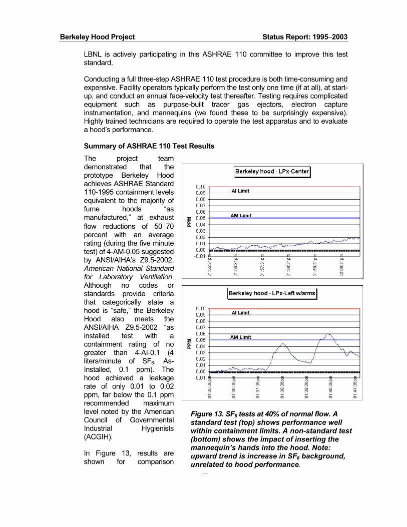
Berkeley Hood Project Status Report: 1995−2003
LBNL is actively participating in this ASHRAE 110 committee to improve this test standard.
Conducting a full three-step ASHRAE 110 test procedure is both time-consuming and expensive. Facility operators typically perform the test only one time (if at all), at start-up, and conduct an annual face-velocity test thereafter. Testing requires complicated equipment such as purpose-built tracer gas ejectors, electron capture instrumentation, and mannequins (we found these to be surprisingly expensive). Highly trained technicians are required to operate the test apparatus and to evaluate a hood’s performance.
Summary of ASHRAE 110 Test Results
42
The project team demonstrated that the prototype Berkeley Hood achieves ASHRAE Standard 110-1995 containment levels equivalent to the majority of fume hoods “as manufactured,” at exhaust flow reductions of 50−70 percent with an average rating (during the five minute test) of 4-AM-0.05 suggested by ANSI/AIHA’s Z9.5-2002, American N Standard for Laboratory Ventilation. Although no codes or standards provide criteria that categorically state a hood is “safe,” the Berkeley Hood also meets the ANSI/AIHA Z9.5-2002 “as installed test with a containment rating of no greater than 4-AI-0.1 (4 liters/minute of SF6, As-Installed, 0.1 ppm). The hood achieved a leakage rate of only 0.01 to 0.02 ppm, far below the 0.1 ppm recommended maximum level noted by the American Council of Governmental Industrial Hygienists (ACGIH).
ational
In Figure 13, results are shown for comparison
Figure 13. SF6 tests at 40% of normal flow. A standard test (top) shows performance well within containment limits. A non-standard test (bottom) shows the impact of inserting the mannequin’s hands into the hood. Note: upward trend is increase in SF6 background, unrelated to hood performance.

Berkeley Hood Project Status Report: 1995−2003
between a “standard” ASHRAE test condition and a test with insertion of the mannequin’s arms into the hood (a more stringent requirement than that called for in the formal ASHRAE 110 tests). Note that not only is the average tracer gas concentration below the “passing” AM limit, the “background level” of tracer gas is increasing, which skews the results towards the “failure” limit. Tests of standard fume hoods indicate that arms inserted into the hood’s cavity cause spillage of the tracer gas due to the “shadow” created by the mannequin’s arms.
Tracer-gas tests were performed on the final prototype before relaying specifications
Evaluate Performance Envelope
A range of empirical test runs were completed on the prototype hood to establish an
Study Operational Envelope distinct supply input plenums; top, front, and lower.
ASHRAE 110-1995 test methods were used throughout this first phase of the
• Theatrical smoke escaped when supply volume equaled or exceeded
• xceeded 85 percent
• ainment was achieved when supply flow rates were in the
• ingular and multiple supply
to Labconco for manufacture. The SF6 detection was performed using a Foxboro Miran 1a, with the inlet tube located at the nose of the mannequin, at exhaust rates equal to 40% of those for standard hoods.
operational envelope. These runs are part of establishing the hood’s performance under varying operation regimes. Parameters varied during these empirical test runs included total exhaust volume and individual supply fan volumes. Safe levels of containment were verified with tests per ASHRAE 110 standards. More work is required to establish this operational envelope under a variety of “real-world” conditions.
The Berkeley hood uses threeEach plenum’s airflow impacts the hood’s ability to contain for a particular exhaust flow rate. The question is; “To what degree is the containment influenced by variations in each supply’s input, individually and in combination?” Some answers to this question have been discovered. A study was performed that began to explore the limit (maximum and minimum) of each supply’s volume flow rate, individually and in combination, that maintains containment performance. For the purposes of this study, these limits define the hood’s “operational envelope.” See Operational Envelope study in Appendix P.
envelope study. Containment evaluations included quantitative tracer gas, SF6, tests and theatrical smoke tests, which served as a visual indicator. Primary conclusions follow:
exhaust volume, indicating a failure to contain. Consistent failures were noted when the push volume eof total exhaust volume. Occasional failures were noted at 80 - 85 percent of total exhaust. Consistent contrange of 60 to 70 percent of total exhaust flow. Thorough examinations of flows below 60 percent were not completed. Containment tests were performed with s
43 plenum(s) inoperative, but an comprehensive evaluation was not completed.

Berkeley Hood Project Status Report: 1995−2003
Accordingly, only operating the lower plenum yields better readings than running only the top, or front plenums during the limited number of test runs. This may indicate that the lower plenum is more effective than the other plena on their own due to the “heavy weight” (with respect to standard air) of the tracer gas. A tracer gas lighter than air would perhaps indicate better performance with the top and front plena rather than the lower plenum. Refer to ASHRAE 110-1995 for additional guidance. The relative “heaviness” of SF6 tracer gas • necessitates employing the
• te caused
Upgrade Lighting
LBNL’s Lighting Systems Research Group developed an improved lighting system for
ASHRAE 110 sash traverse in all fume hoods. Standard hood designs do not contain well at the front edge of the work surface, which is low in the hood. In the case of the Berkeley test of hood this test procedure is also important during testing of low push-rates, e.g., less than 30 percent push. Some test runs while operating the front plenum at a “high” flow raoccasional spillage, but an comprehensive evaluation was not completed. Therefore, it is unclear whether spillage is caused by the resulting high velocity or high volume; we suspect high velocity. Generally, high flow rates from the front plenum decrease containment. Increasing the front plenum’s outlet opening would reduce the outlet velocity for the same volume flow rate.
the Berkeley Hood (Figure 14). They performed a thorough evaluation of a standard hood’s lighting system to provide a design baseline. Next, the Berkeley Hood’s interior geometry modifications were studied and incorporated into an upgraded lighting system. Standard lighting system of two T-12 lamps and magnetic ballasts was discarded. The new lighting system uses a single T-5 lamp, an electronic ballast, and specially made asymmetric parabolic reflector. Lighting quality and efficacy is improved while energy use is reduced from 66 watts to 36 watts, i.e. 47 percent. Additional benefits include increased reliability and safety, reduced maintenance thanks to longer lamp life, and more uniform illumination (Figure 15) across the work area (Mitchell et al. 1999, see Appendix N).
Figure 14. Standard hood lamp and p fixture (top) and energy-efficient lam
with reflector (below).
44

Berkeley Hood Project Status Report: 1995−2003
Figure 15: Iso-lux plots at task level for both baseline fixture and LBNL prototype fixture
Market Development
The ultimate goal of the Fume Hood project is to ensure that the technology is commercialized and widely deployed. Our approach follows five major pathways:
• Develop the technology and user interface
• Establish partnerships with hood manufacturers
• Identify and overcome market and regulatory barriers
• Perform outreach activities
• Publicize project results
Within the technology development work—as described elsewhere in this report—we have implemented field tests, evaluated the installations, and collected user feedback. Experiences and lessons learned from the field test program lead to refinements in the hood’s design and improved understanding of its operation. An important first step in the field test program was to establish working partnerships with companies that have experience and industrial resources to assist research efforts. The market-barrier task identified several considerable issues. Outreach activities have been highly successful. Several important industrial partners have been identified, including some of the larger manufacturers of fume hoods, as well as other important associations (controls manufacturers, etc.). Three manufacturers have
45

Berkeley Hood Project Status Report: 1995−2003
already manufactured prototype hoods. In support of our outreach efforts, we have seen a good level of publicity for the Berkeley Hood activities
Securing rights to intellectual property (IP) developed from technological improvements realized during research is very important. Interfacing with the U.S. Patents and Trademarks Office (PTO) was accomplished with help from an outside law firm.
Secure Patents Protection
Background LBNL staff and summer students performed a literature search for patent application features. Some related work was performed by our industrial partner but a more extensive effort was required. To the best of our knowledge, all patents relative to laboratory chemical/biological fume hoods were identified (Vogel 1999).
Complete Patent Application The project team worked closely with LBNL’s patent attorney and the U.S. Patents and Trademarks Office (PTO). A patent application is comprised of two main parts: the specifications and the claims of the invention. Typically, after a patent application has been filed, the PTO will respond with an “office action”. In the first office action, most of LBNL’s original patent application was rejected in both the specification and claims sections. While not unexpected, it was necessary to extensively re-evaluate the claims made in the original application.
The basis for rejection was on prior illustrations in previous patents. Each of the patents cited had relative similarities to the Berkeley Hood; however, in each case, there were important differences that distinguished our high-performance, air divider fume hood approach from other design concepts. The Berkeley Hood has a unique design that uses already-conditioned laboratory air. The hood’s auxiliary fans direct the laboratory air through fan vents and over the work surface in a unique push-pull ventilation system.
Ultimately, U.S. Patent #6,428,408 entitled “Low-Flow Fume Hoods” was awarded, covering design and geometry enhancements anticipated by the first patent, e.g. grill configurations, interior modifications, and rear-baffle design.
Patent Timeline The following timeline summarizes patent-related activities.
April 1998Submitted base patent application
July 1999U.S. Patent Office (PTO) issued its first “office action,” rejecting LBNL's specification and set of claims.
August 4, 1999— meeting with consulting patent attorney to discussed how to restructure the specification and claims for a second Office Action review.
46

Berkeley Hood Project Status Report: 1995−2003
October 1999LBNL resubmitted to the PTO. A revised, narrowed specification and a clarified set of claims was written and resubmitted. Particular revision information clearly states that LBNL’s technique uses laboratory air that has already been conditioned and directs this air through supply fan vents over the hood’s interior work surface in a unique push-pull ventilation system. Further, it accomplishes this with “low turbulence intensity.” The technique also allows a significant decrease in energy use to achieve containment while maintaining, if not improving, operator safety.
February 10, 2000PTO "allows" the patent by accepting the revised application.
May 1999 to Feb 2000Throughout this time period significant improvements were made to the original hood configuration. It was resolved that these achievements warranted filing additional clarifications and claims as a “continuation-in-part” (CIP) to the original patent. This CIP needed to be filed prior to the PTO issuing an “original” or “base” patent describing the technology.
May 2000LBNL files "continuation in part," establishing patent rights to two hood design improvements identified since the initial patent application; design improvements include: (1) supply plenum size, position, and shape, and (2) interior baffle arrangements, perforations, and slot exhaust port.
July 19, 2000PTO issues patent #6,089,970 to LBNL for "Energy efficient laboratory fume hood."
March 13, 2001The "Continuation in Part" to the patent issued in July 2000 was rejected by the PTO in an Office Action. A response by LBNL's patent attorney was filed in May 01 stating our reasoning to allow the claims.
August 6, 2002 -- U.S. Patent #6,428,408 awarded.
Identifying Market Barriers
Background The ASHRAE 110-1995 guideline is a performance test method and does not provide safety ratings. Therefore, organizations that issue standards and recommendations must supplement ASHRAE 110 by providing “target values” for tests results. These values are intended to indicate a hood’s relative performance between safe and unsafe.
Two evaluation procedures in ASHRAE 110-1995 are quantifiable and can be assigned target values to indicate a “safely” operating fume hood. They are the face velocity test, in feet per minute (FPM), and the tracer gas containment test, in parts per million (PPM) leak of SF6 tracer gas when ejected at a particular rate inside the hood. Acceptable values for these tests are provided by various standards organizations.
47
Since ASHRAE 110-1995 does not specifically stipulate what face velocity (in FPM) is “safe”, it is left up to “the authority having jurisdiction” to decide a face velocity that will
Berkeley Hood Project Status Report: 1995−2003
provide operator safety. Most standards recommend an average face velocity “target value” of 100 FPM. Unlike standard fume hoods, the Berkeley Hood containment method decouples face velocity from containment and, thus, safety performance. Consequently, recommendations of 100 FPM face velocity present the most significant implementation barrier to using the Berkeley Hood.
Reliance on Face Velocity Nearly all manufacturers test their fume hood designs per the ASHRAE 110-1995 method. It is a very comprehensive test that can be time-consuming and expensive. To minimize testing cost and complexity of commissioning fume hoods, installers are typically required to perform only part of the ASHRAE 110 hood protocol, specifically face velocity tests. These face velocity tests are normally the sole basis that a facility operator/owner uses to indicate the containment performance of their hoods.
Further entrenching face velocity as the only test for examining an installed hood is recurring testing requirements, usually annually. Most organizations can only afford to administer an annual face velocity test, while thinking this is an adequate test for determining hood containment. In many cases, a hood that passes a prescribed face-velocity test fails the ANSI/AIHA tracer-gas test threshold.
Face Velocity Questioned Reliance on face velocity testing as the sole method to assure a worker that their hood is containing fumes has been called into question by leading experts in the field of fume commissioning and testing.
A study by Dale Hitchings (1996), an industry consultant, noted that 59 percent of the hoods passed face velocity criteria. However, only 13 percent of the hoods passing the face velocity criteria met tracer gas standards set by industry.
Another report shows that 30 to 50 percent of hoods leaking excessive levels of contaminants still pass the traditional face velocity tests (Hitchings and Maupins 1997). These failure rates have been confirmed by other fume hood testing experts (Knutson 2001; Smith 2001).
In another study, an investigator found that in a properly designed laboratory, fume hoods with face velocities as low as 50 fpm provided “…protection factors…” 2,200-times greater than hoods with face velocities of 150 fpm. (Caplan and Knutson 1977).
Another set of tests indicated that with the exception of one particular type of hood operation, there was no difference in hood containment with face velocities between 59 and 138 fpm. (Ivany et al. 1989).
At some laboratories, 60 or 50 fpm has been accepted (Saunders 1993).
Alternative Test Methods Review LBNL's project team contacted several industrial hygienists, EH&S personnel, and other experts in the fields of fume hood testing and certification to help develop
48
Berkeley Hood Project Status Report: 1995−2003
methods or recommendations for testing the Berkeley Hood. Many potential hood test procedures and methods were identified (Griffin 1999). The new hood tests were compared and evaluated. Empirical evaluations need to be conducted.
User Tracer Gas Testa variation of the ASHRAE 110-tracer gas test using a human subject instead of a mannequin. As in the original test procedure, all facets of the ASHRAE-110 tests are followed. This user tracer gas test was performed with a human subject standing in front of a hood making consistent, prescribed movements, such as extending both arms into the hood and pulling them back out in one motion every 30 seconds (Altemose et al. 1998).
Air Monitoring Testa very simple test, but may require several days to collect useful data. In this method a user wears an air-monitoring device in the breathing zone while working in the hood and the test staff evaluates contamination levels at various velocities.
In-Use Testing Proceduresimilar to the User Tracer Gas Test but using other vapors and detectors while hood operators conduct normal hood activities. SF6 was used in the original study, but other vapors and detectors could be used. It was designed to assess fume hood performance during normal work activities. Escape of the “challenge” gas is measured in the operator’s breathing zone by a direct reading instrument (Ivany and DiBerardinus 1989)
Dioctylphthalate (DOP) TestDOP is a part of the NSF 49 test for Biological Safety Cabinets (BSCs) used to stimulate particles of less than 3 microns in size. In BSCs, this test is performed to determine the integrity of supply and exhaust HEPA filters, filter housing, and filter mounting frames while the cabinet is operated at the nominal set point velocities. An aerosol in the form of generated particulates of dioctylphthalate (DOP) is required for leak-testing HEPA filters and their seals. A recent research study (Joao et al. 1997) suggests that a more quantitative approach, using the NSF 49 procedure, might lead to a better understanding of fume hood limitations, and help evaluate exposure to not only the fume hood worker, but those sharing the laboratory as well. The test proceeds in the following manner: A DOP aerosol generator operated at 20 psi is connected to a metal canister 7 inches in diameter. The canister’s open top is covered with 1-inch-thick open-cell foam to allow a relatively even discharge of aerosol in the geometric center of the fume hood work zone, approximating an aerosol emitting from a large beaker in the hood where the outer edge of the vessel was 10 inches behind the sash. DOP is released at 150 L/min. An aerosol photometer is employed to detect aerosol escape from the face of the hood. At the fume hood’s face opening, the photometer probe is passed from left to right across the plane of the face, one inch in front of the opening in 1-inch-wide rows from top to bottom and readings are recorded. At the face opening a concentration reference point is recorded 4 inches in the work zone in the center of the face opening.
NIOSH Method 1500a test using special air sampling pumps (e.g. SKC Model, Gillian, MSA Personnel Pump), a human subject, and NIOSH Method 1300 equipment. This is an expensive alternative to other methods noted here.
49

Berkeley Hood Project Status Report: 1995−2003
Photo Ionization Detector (PID) TestPIDs monitor the concentration of toxic gas. These units have many applications in industry, at utility companies, and by fire fighters. Additionally, environmental consultants use PIDs to detect small traces of toxic gas, monitor hazardous waste, inspect leaking underground storage tanks, and monitor personnel exposure.
CO2 Testa simple test where a palm-sized CO2 packet is placed inside the fume hood. As the CO2 is emitted, an air monitoring device or wand is used to capture and record the amount of spillage. This test is ideal in terms of expense, time, and portability. This makes the test seem a very promising choice. However, the drawback to using CO2 is the chance of producing erroneous values due to human CO2 production and normal "background" fluctuations.
Based on this review, no methods clearly superior to SF6 testing were identified. However, it is important to keep in mind that instrumentation for detecting SF6 could register other leaking refrigerants as a false positive. It is also notable that, as part of the CFC phase-out goals for 2010, SF6 may no longer be available for use as a new tracer gas.
Alternative Approach for the Berkeley Hood Since ensuring worker safety is everyone’s concern, the following approach is offered that minimizes the cost of testing Berkeley hood installations. In a particular laboratory building, the SF6-challenge test is performed initially on a representative number of hoods in laboratories of similar design. The designer or owner determines how many hoods will be tested. The ANSI/AIHA tracer gas standard then indicates that once acceptable containment is determined, “Berkeley-hood face velocity” and smoke visualization tests can then be used as subsequent surrogate measurement of performance, provided no significant changes are made in the hood or laboratory design. This “Berkeley-hood face velocity test” includes: measuring the face velocity with the supply plena push-fan(s) turned off (main exhaust pull-fan is operating) per the ASHRAE 110 method and measuring the outlet velocity of each supply plenum (with the main exhaust pull-fan operating). These data are then recorded and verified annually, in the same manner as standard hood installations.
Overcoming Regulatory Barriers
Uniform building, mechanical, and electrical codes; state and federal OSHA regulations; and Fire and Safety regulations (specifically NFPA) were studied with respect to laboratory “fume” hood installations. When adopted by local jurisdictions, these codes and regulations “carry the force of law.” Many regulations make reference to certain industry standards and guidelines. Potential barriers to using the Berkeley Hood were noted in these existing protocols and “standard” design guidelines (especially ASHRAE and ACGIH) (Vogel 1999; Fox 2000).
The only state in the U.S. that prescribes a particular face velocity is California, specifically, by CAL/OSHA. Cal-OSHA relies solely on an average face velocity of 100 FPM to indicate a “safely” operating hood. The current Berkeley Hood configuration has a equivalent face velocity of 30 to 50 FPM. Upon hearing this, most dismiss the Berkeley Hood as being unsafe, yet it passes flow visualization and tracer
50

Berkeley Hood Project Status Report: 1995−2003
gas tests that are far superior and more rigorous for determining containment and safety.
Participate on Standards Committees At present, surrogate measurements that do not directly measure a hood’s ability to contain hazardous fumes, vapors, or substances hold sway in determining efficacy by most testing “standards” cited by standards committees. Participation on various standards committees can help garner acceptance of the Berkeley Hood’s high-performance air divider technique. Fundamental arguments regarding safety and containment capabilities of laboratory-type hoods need to be presented to committee members.
ASHRAE SPC-110 Committee
The ASHRAE Guideline ANSI/ASHRAE 110-1995, Method of Testing Performance of Laboratory Fume Hoods is revised on a ten-year cycle. The next revision is due to be published in the year 2005. ASHRAE announced the formation of the SPC-110 committee (June 2000) to revise the guideline, with LBNL staff among the members.
The LBNL project team is currently working in four specific areas of interest that will be eventually addressed by the full committee including:
Specialty hoods
Ejector design and flow rate
Effect of turbulence intensity
ASHRAE vs. other standards
CAL/OSHA Advisory Committee
CAL/OSHA was petitioned by two private industry members to amend their stance on requiring all hoods (except for those working with 13 known carcinogens) to have 100 FPM face velocity. One petition requested revising Section 5154.1.c to entirely replace the current prescriptive face velocity requirement, for fume hood operations, with a performance test requirement, specifically, tracer gas testing.
In response, CAL/OSHA convened the advisory committee to the Standards Board to review and recommend changes proposed to their standard 5154.1 Ventilation Requirements for Laboratory-Type Hood Operations. LBNL staff participated on the Advisory Committee to help Cal/OSHA review the two petitions. The advisory committee developed a revised Section 5154.1 that including this type of alternative performance tests that could be performed, instead of a face velocity test, as an indicator of equivalent performance. The current face velocity test method was not removed and could be used by a hood operator, if so desired. The committee struggled with stipulating a "floor" face velocity. This struggle goes to the heart of the matter: Can CAL/OSHA establish a standard that helps workers be "safe" and not be prejudicial against some fume hood technologies?
51

Berkeley Hood Project Status Report: 1995−2003
Changing CAL/OSHA Standard 5154.1 CAL/OSHA personnel visited LBNL to observe a demonstration of the hood, and extended an invitation to develop “new language” to describe testing for the push-pull hood and to assist in developing the language for variances required for demonstration projects. LBNL’s Environmental Health & Safety Department provided support to craft the “new language” and the variance application.
The new language is a "performance-based compliance specification." The specification is an attempt to build a performance-based standard while the existing standard can be considered a prescriptive-based standard. The approach is predicated upon acceptance of an "either, or" compliance doctrine, i.e., of a prescriptive or a performance hood evaluation methodology, by the whole committee.
LBNL’s proposed, "alternate" standard is intended to be used only if the "authority having jurisdiction" decides not to use the existing CAL/OSHA prescriptive standard that requires a face velocity test. Contemplating the merits of using tracer gas testing for measuring laboratory-type hood containment performance, worker protection is not well served by only allowing face velocity measurements as the sole performance indicator.
Berkeley Variance Hearing An application for a variance to testing a laboratory-type hood to a prescriptive face velocity was filed at CAL/OSHA. In December 2002, a hearing was held before the CAL/OSHA Standards Board (the Board) to get a ruling on an application for a variance to operate a Berkeley hood in California (specifically at San Diego State University (SDSU)) to a performance-based test, namely, a tracer gas test (per ANSI performance standard). No resolution was reached regarding identification of an "equivalent performance indicator" to CAL/OSHA’s face velocity standard. Consequently, a "continuance" to get additional information was granted to support our variance application. Per the Board’s guidance, we then sought review of the "face velocity" test-approach from an organization respected by CAL/OSHA, namely ANSI (American National Standards Institute). See Appendix AD.
Interpretation Request
Accordingly, in February, 2003, an interpretation was requested of ANSI/AIHA regarding an “equivalent performance indicator” comparable to a face velocity test. The wording of this request was reviewed by CAL/OSHA staff and included their additional discussion topics for ANSI’s consideration. In June 2003, we received a response to the inquiry requested from ANSI/AIHA for them to advise an equivalent hood performance indicator to a face velocity test. Stated in their response; ANSI firmly "requires" a tracer gas test that ANSI considers "superior" to a face velocity test. The Berkeley hood has successfully passed many tracer gas tests.
ANSI/AIHA Response
Included, below, is an excerpt for the interpretation response letter we received from ANSI/AIHA that supports our position for a performance-based test:
52

Berkeley Hood Project Status Report: 1995−2003
In summary it seems that your specific design of hood may not lend itself well to evaluation solely by face velocity tests. It is for this very reason that Section 3.3 was written from a performance-based aspect. The current document [ANSI/AIHA Z9.5-2002] indicates that containment, and not face velocity is the primary performance criteria. That is the reason additional information is provided on the right side (advisory) on containment testing. In section 3.3.2 it is stated that:
“Once adequate performance has been established for a particular hood at a given benchmark face velocity.... that benchmark face velocity shall be used for a periodic check...”
No face velocity limitations are stated in the mandatory wording. Guidance is provided in the advisory language for typical situations. Clearly, your design is not typical, and if effective containment can be demonstrated at a lower face velocity than that provided in the guidance, it would appear that this particular hood was in conformance with this aspect of ANSI/AIHA Z9.5-2003.
We feel these statements clearly rank face velocity as subordinate to tracer gas containment testing. This is consistent with the variance application and the formal interpretation from ANSI/AIHA which states, “the tracer gas portion of ASHRAE 110 with an as installed performance of 4 liters per minute at 0.10 ppm is a superior test of fume hood safety and containment than simply verifying the hood as having 100 feet per minute of average face velocity.” See Appendix AC.
ANSI/AIHA success While Cal/OSHA staff seems recalcitrant to evolve beyond the low-cost, easy to measure, face velocity standard, industry leaders are recognizing its limitations as an indicator of containment and, thus, safety. ANSI, who promulgated the face velocity standard originally adopted by Cal/OSHA, now strongly recommends against its sole use as a performance test. Their newly adopted standard Z9.5-2002 requires using the more meaningful, tracer gas testing (a performance test of containment). Experts have found that many hoods passing a face velocity test fail these more robust containment tests. Moreover, this latest version of Z9.5 provides guidelines for worker safety without restricting innovative containment technologies newly available in the marketplace.
Implement Hood Field Test Program
Experiences and lessons learned from the LBNL’s field test program described below have already led to refinements in the hood’s design and improved understanding of its operational envelope. An important first step in the field test program was to establish working partnerships with companies that have experience and industrial resources to assist research efforts. See Appendices B, C and D.
Establish Industrial Partnerships Partnerships have been established with research organizations, commercial hood manufacturers, and control companies. Industrial partners have built “alpha” prototype Berkeley Hoods used in the field tests. The most current design information is transmitted to our partners on a regular basis.
53

Berkeley Hood Project Status Report: 1995−2003
A close association with Pacific Gas and Electric Company’s Food Services Technology Center (FSTC) was formed early in the development process. This Center studies and evaluates commercial kitchen devices, including those that use exhaust hoods to remove waste heat and fumes. There is a great amount of similarity in the goals of a kitchen exhaust hood and a laboratory fume hood to remove unwanted air. A flow-visualization tool used at the FSTC, called a schlieren device , was borrowed by LBNL for testing the Berkeley Hood. A set up of the complex schlieren tool was completed at LBNL. We performed extensive evaluations of the Berkeley Hood, produced videos of test runs, and archived videos of the schlieren work on CD-ROMs.
Labconco became our first industrial partner. In May 1999, Labconco shipped a standard fume hood superstructure to LBNL. It was modified to become our first operational prototype. Containment was achieved in June 1999. Research and modifications continued until December 1999 when the design was provisionally “frozen.” An evaluation commenced to determine the hood’s performance envelope and to establish its operational safety testing until June 2000 (see Appendix V, LBNL Final Prototype Hood).
Labconco provided industrial “muscle” to build the alpha generation of Berkeley Hood. This prototype was assembled in August 2000 and delivered to PG&E’s Pacific Energy Center the first week of September. At the Center, the hood was made operational and displayed for the Laboratories for the 21st Century conference attendees. The hood was returned to LBNL for further tests and refinements prior to installation at UCSF.
The most recent industrial partners are Jamestown Metal Projects and Tek-Air Systems, who helped develop a second-generation hood prototypes and controls for hoods with wider sash openings (six feet).
Significant Support
Additional support from other industrial partners has provided significant insights and improvements to building a viable Berkeley Hood. These companies include: Siemens Controls, U.S. Filter/Johnson Screens, Technical Safety Services Company, ATMI, and Fisher-Hamilton. The field test sites themselves have made significant contributions. For example, UCSF contracted for and funded mechanical and electrical system upgrades to accommodate the field test hood. See Executive Summary for a complete list of our industrial partners.
Perform Field Tests Field tests of an alpha-generation of the Berkeley Hood are ongoing. These trials have increased our understanding of operability of the Berkeley Hood under actual working conditions in functioning laboratories.
Trial Sites
Tests are completed or in progress at three sites. The first is sponsored by NIST at Montana State University. The second is sponsored by PG&E at UC San Francisco
54

Berkeley Hood Project Status Report: 1995−2003
(see Appendix X). The third is sponsored by San Diego Gas and Electric Company, at San Diego State University.
These first trial sites were picked because campus personnel are highly regarded and have professional Environmental, Health, and Safety (EH&S) and facilities staff to assist with implementing the test.
The California Energy Commission has sponsored an additional set of demonstrations to be conducted at industrial locations in California, the first of which is the National Food Laboratory (in Dublin, CA). These will be conducted using hoods manufactured by Jamestown Metal Products.
Field Test at Montana State University
In 1998, Montana State University (MSU) established plans to build an environmentally friendly “green” laboratory facility. The building was to incorporate state-of-the-art mechanical and electrical systems to provide occupants with a high-quality environment with low energy-use requirements. MSU staff researched cutting-edge technologies and discovered the Berkeley Hood. MSU funded LBNL’s development and field test efforts. LBNL worked with their hood supplier, Fisher-Hamilton (F-H), to develop a field test unit for the site (Figure 16). LBNL researchers developed a prototype hood from a F-H superstructure, which was installed at LBNL’s test lab in late 1999 (see Appendix E and M). LBNL then:
completed extensive modifications of standard F-H fume hood for field test of in February 2000.
modified the design further to accommodate new requests by F-H and passed the ASHRAE 110 test, performed by F-H personnel
shipped field test unit to arrive at F-H by end of March 2000.
attended additional testing at F-H”s fume hood facility by independent testing company in August 2000.
installed newly fabricated unit at MSU in September 2000.
Table 2 summarizes Fisher-Hamilton's test results. They found that when tested per ASHRAE's Standard 110-1995 protocol, the prototype hood contained smoke and operated at significantly less than 0.10 ppm leakage; a maximum level recommended by the American Council of Governmental Industrial Hygienists (ACGIH).
Figure 16. Fisher-Hamilton alpha prototype Berkeley Hood.
55

Berkeley Hood Project Status Report: 1995−2003
Table 2. Fisher-Hamilton’s test results at Montana State University. Test Stand.
ASHRAE 110
Mannequin Height
(inches)
Sash
Height
(inches)
SF6 Release Rate
(liters/minute)
Tracer Gas Ejector Test Position & Resulting SF6 Concentrations in The Hood
(ppm SF6)
Worst-case Hood Rating (target <0.10 ppm)
Left Center Right (ppm SF6)
1 Yes 26 25 4 < 0.01 <0.01 <0.01 <0.01
2 No 18 25 4 <0.01 <0.01 <0.01 <0.01
3 No 18 31 4 0.05 0.04 0.01 0.05
Field Test at UC San Francisco
With support from PG&E, a field test Project was initiated in March 2000. The project staff identified a field site at UC San Francisco’s Medical Radiology Center in a pathology laboratory building. We began evaluating the site and potential installation challenges. Fabrication and installation work began in late April and lasted until October 2000.
A kick-off meeting with UCSF personnel, our industrial partners, Labconco, Siemens Building Controls and UCSF’s mechanical contractor, Marina Mechanical, was held at UCSF on 1 August 2000. On the same day, a baseline ASHRAE 110 test of an existing fume hood was performed in the Pathology Lab. The existing hood failed the ASHRAE 110 protocol according to CAL/OSHA Standard 5154.1 and recommendations per ANSI Z9.5 in its normal operating mode. These readings were taken with the lab in its "normal" operating mode (as-used) that included some "clutter" in the hood, one missing ceiling tile, and an opened operable window. All of these items could contribute to the low 50-FPM face velocity reading.
The Berkeley Hood became operational on 17 November 2000 (Figure 17). ASHRAE 110 testing by LBNL and Siemens Building Controls was performed on 5 December 2000. Flow deficiency was noted in the lower plenum, although the hood passed all ASHRAE 110 requirements. Evaluations and modifications were completed.
Figure 17. Labconco alpha prototype Berkeley Hood at UC San Francisco.
56

Berkeley Hood Project Status Report: 1995−2003
The installation includes several novel features, including:
A special Siemens control package that included alarms on the supply fans.
An interface with the building exhaust fans to alert hood users if the fans failed.
A purge feature with an override button that forces hood operation to full flow if the user encounters a spill or evidence that the hood is not containing the effluent.
Modified and auxiliary ASHRAE 110 tests were also conducted, simulating “as-used” operating conditions. The current version of the Berkeley Hood has performed quite well and, in some cases, exceeded expectations (Table 3). The hood contained the smoke and tracer gas under all conditions down to 34 percent of full flow (see Appendix V, UCSF/Labconco Alpha Hood).
Table 3. ASHRAE 110 test results for Labconco unit at UCSF. Test Type
Test Conditions
Airflow % of "normal" (100 fpm)
Berkeley Hood Containment AM (as mf’g)
Berkeley Hood Containment AI (as installed)
Berkeley Hood Containment AU (as used)
Standard (Existing.) Hood Containment @ 100 FPM
Smoke Small volume Smoke tube
50% Good Good Good
Fair
Face Velocity a Sash Full Open 50% N/A N/A N/A Fail Tracer gas b Sash Full Open;
three positions 50% Pass Pass Pass Fail c
Tracer gas b Sash movement; three positions
50% Pass Pass Pass N/A
Tracer gas b Safety margin check
50% Pass Pass Pass N/A
Tracer gas b Sash full open; Three positions; breathing zone @ 18 inches
50% Pass Pass Pass N/A
Tracer gas b Sash movement; three positions; breathing zone @ 18 inches
50% Pass Pass N/A N/A
Tracer gas b Sash full open; breathing zone @ 18 inches
40% Pass Pass Pass N/A
Tracer gas b Sash full open; breathing zone @ 18 inches
33% Fail Fail Fail N/A
a.Face velocity Pass/Fail criterion per CAL/OSHA 5154.1. b. Tracer gas Pass/Fail criterion per ANSI Z9.5 1992. c. Fail criterion per NIH (1996); marginal pass per ANSI Z9.5 1992. N/A = not applicable or not done
Field Test at San Diego State University
During the summer of FY 2001, three nationally recognized experts in the field of fume hood testing and commissioning visited LBNL to conduct extensive tests on a prototype Berkeley hood provided by Labconco. Each expert prepared recommendations to improve hood performance. Appropriate modifications were then made to the field demonstration unit. Improvements included altering the amount of airflow inside of the hood "behind" the sash, increasing effectiveness
57

Berkeley Hood Project Status Report: 1995−2003
of airflow "sweeping" the work surface inside the hood, and addressing "lazy and reverse flow" inside the hood under certain situations. Some of these improvements resulted from employing new ejector designs being developed by two of the consultants. Test results for the new prototype are described in the following section. The hood was subsequently delivered to San Diego State University to serve as the third field test unit.
Lessons Learned from Field Studies & Hood Modifications
Table 4 describes technical improvements made to the Berkeley Hood based on observations and performance of the prototypes at LBNL. “High priority” items were implemented for the field test hood installed at UCSF. All improvements were incorporated into the version for the San Diego State University site. One example of such improvements involved enhancing airflow velocity along the work surface (floor) of the hood, referred to as “floor sweep” (see Fig. 18, below).
Figure 18. SDSU hood demonstrating floor sweep with point-source smoke.
58

Berkeley Hood Project Status Report: 1995−2003
Table 4. Technical improvements to the Berkeley Hood based on field tests. Problem Results Solution Priority Lower plenum H, M, L
Supply fan too close to plenum box
caused reverse flow into plenum due to high velocities near fan outlet
1. Added additional fan housing (without fan blades or motor) to provide longer run before fan flow enters plenum box
2. Added tape over first 2 inches of screen in plenum box.
H
Hole into plenum box too small compared to fan blade’s outside diameter.
Reduced volume flow of fan greatly
Added additional fan housing (without fan blades or motor) to provide longer run before fan flow enters plenum box. (Hole could not be enlarged.)
M
Front Plenum Hole into plenum box too small compared to fan blade’s outside diameter.
Reduced volume flow of fan greatly
Enlarged hole (Not addressed at this time).
M
Front cover of hood (with logo) blocks airflow to front plenum supply fan
Reduced volume of fan flow greatly
Provided different inlet hole to fan.
H
Screen does not seal properly on right side of hood.
Leaking screen upset airflow pattern into hood.
Adjusted plenum box to provide sealing surface.
H
Top Plenum Hole into plenum box too small compared to fan blade’s outside diameter.
Reduced volume of fan flow greatly
Not addressed at this time. M
Rear (Back) Baffle Top-most section of rear baffle does not extend into outlet slot.
Strong airflow behind baffle is not initiated thus reducing sweeping action at hood’s counter top (work surface).
Fabricated new top baffle section
H
Top-most section of rear baffle needs to be set at an angle so 60 percent of airflow is behind baffle and 40 percent is in front.
Strong airflow behind baffle is not initiated, thus reducing sweeping action at hood’s counter top (work surface).
Adjusted new top baffle section so that a 2 inch opening is in front of baffle with 3 inches behind.
H
SDSU Prototype The SDSU prototype was tested according to standard ASHRAE-110 procedures, (Bell 2002). Figure 19 shows the excellent performance at 30 percent of normal flow under the standard test. However, with a Sash Movement Effect (SME) test, per ASHRAE 110 Section 7.12, concentrations momentarily rose above the As Manufactured (AM) levels (see Appendix V, SDSU/Labconco
59

Berkeley Hood Project Status Report: 1995−2003
Apha Hood, Rev. 2). The Berkeley demonstrated its ability to recover from this disturbance by still passing the ANSI performance test with an average value for the five minute test period of less than 0.05 ppm (Figure 20).
0
0.01
0.02
0.03
0.04
0.05
0.06
0.07
0.08
0.09
0 20 40 60 80 100 120 140 160 180 200 220 240 260 280 300
Time (sec)
Figure 19. SDSU prototype, no sash operation.
Run #430% Flow @ 26 in.
(72701_C)
0.1
0.11
0.12
0.13
0.14
0.15
Concentration of SF6
As Installed (AI) LimitAs Manufactured (AM) Limit
Run #650% Flow @ 26 in.
(72701_E)
0
0.01
0.02
0.03
0.04
0.05
0.06
0.07
0.08
0.09
0.1
0.11
0.12
0.13
0.14
0.15
0 20 40 60 80 100 120 140 160 180 200 220 240 260 280 300
Time (sec)
Concentration of SF6
As Installed (AI) Limit
As Manufactured (AM)
Figure 20. SDSU prototype, with sash operation and increased supply flows.
60

Berkeley Hood Project Status Report: 1995−2003
D
en widely distributed in both paper and electronic formats. A lengthy review process ensured that the
ence. See Appendix Z.
evelop Outreach Activities
Create Laboratory Hood Brochure The project team developed a four-page informational brochure in the summer of 2000 that gives a clear overview of the Berkeley Hood (LBNL 2001) Using color photos and graphics, the brochure introduces readers to laboratory hood use, demonstrates the energy impacts of hoods in a laboratory environment, gives a brief technical overview of the high-performance, air-divider approach, and describes the hood’s benefits. The brochure has be
brochure suits a wide audi
Deploy Project Web Site The project team developed a Berkeley hood web site which includes a range of content, including a project overview, brochure, video clips demonstrating prototype hood operation, and a market analysis. The project team frequently updates the site with new information. Links to other LBNL resources and other relevant energy
tinuously updated.
e sponsored by FSTC on June 30, 2000 at the Pacific Energy Center in San Francisco. The team continues to pursue ongoing
FSTC.
ctober 2001, University of California EH&S Working Group, PE/ESCO National Meeting in March 2003, Tek-Air, Inc.,
nergy Center, was well attended by at least 75 laboratory professionals. Presented at four iLab conferences in San Diego, Los Angeles, San Francisco, and
information sites is included and con
PG&E FSTC Demonstrations In March 2000 LBNL demonstrated a neutrally-buoyant bubble generator at the annual conference sponsored by PG&E's Food Service Technology Center (FSTC) in San Ramon, California. The team also delivered a presentation on the Berkeley Hood at the Flow Visualization Conferenc
collaboration efforts with the
Prototype Presentations Numerous presentations and demonstrations have been performed at LBNL of the Berkeley Hood for organizations including: Pacific Gas & Electric (PG&E), Southern California Gas Company (SOCALGAS), San Diego Gas and Electric Co. (SDG&E), Southern California Edison (SCE), The U.S Department of Energy, California Energy Commission, Northwest Energy Efficiency Alliance, San Diego State University, UC Santa Cruz, UC Santa Barbara, UC San Francisco, UC Davis, GPR Planners, San Francisco Chronicle, Siemens Controls, Phoenix Controls, Technology Performance Group, CAL/OSHA, ACEEE Reception in O
Jamestown Metal Products, and many others.
Conferences and Workshop Presentations The project team presented an overview of the Berkeley Hood Project to the 1999 EPA/DOE Labs 21 Conference attendees in Boston and at the following year’s conference in San Francisco on September 7, 2000. The team demonstrated the hood at a reception held at during the 2000 conference. The demonstration, held at the Pacific E
Princeton. 61
Berkeley Hood Project Status Report: 1995−2003
Publicity A number of organizations have recognized the Berkeley Hood’s importance and
and have publicized it or otherwise recognized it.
The
le.
ily Californian, Sci-Tech section, 14 February 2000; newspaper and web
lert, 18 Feb. 2000; news article.
arch 2000.
article on the front page of the Business Section,
ch for Researchers. Engineered ) (Sartor, et al., 2002).
am web
Latest Fume Hoods.” Engineered Systems magazine, Vol. 20, No. 7; July 2003.
potential impact
se include:
UniSci – Daily University Science News; 18 Jan 2000; news article.
Laboratory Network.com; News and Analysis web site, 25 Jan. 2000; artic
The Alchemist, trade organization’s web site, 27 Jan. 2000; news article.
The Daarticle.
Daily University Science News, January 18, 2000
E-Source Tech News Vol. 1 Issue 1, 18 February 2000; article.
Advanced Manufacturing Technology A
DOE This Month, March 2000; article.
ATMI’s advertisement in Cleanrooms, Vol. 14, No. 3, a trade journal, M
Patent Announcement in Cleanrooms, Vol. 14, No. 10, October 2000.
San Francisco Chronicle, Sunday, 28 January 2001.
Sartor, D., G. Bell, E. Mills. 2002. ResearSystems (June
FEMP Focus
News from the Hood, a regular news letter publish the Applications Tesite updating subscribers on the latest information on the Berkeley hood.
Turpin, J., “Clearing the Air About the
62

Berkeley Hood Project Status Report: 1995−2003
ANNUAL ACCOMPLISHMENTS
FY03 Accomplishments
This section provides a summary of the work completed during 2002-2003. These tasks were completed with funding from the DOE and the California Energy Commission (CEC) Contract 400-00-020-Am. See Appendix W.
Promoted Industrial Demonstrations
Three (3) industrial laboratories were selected as demonstration sites for Berkeley hood field testing. Selection was based on having typical laboratory installations.
• Promoted hood demonstrations • Solicited and developed interest in participation with
the following potential Industrial Partners: o National Food Laboratory o ChevronTexaco o Genentech o Roche Bioscience o Amgen o Asyst Technologies
• Arranged for Permanent Variance Applications to be submitted by three industrial partners; other partners were eager to participate.
Assisted Hood Fabricator
Design assistance was provide to manufacturer the Berkeley Hood.
• Identified hood fabrication partner • Developed over 25 engineering and fabrication drawings for six-foot
version of Berkeley hood at LBNL (See Fig. FY03-1).
Figure FY03-1: LBNL six-foot Berkeley hood engineering drawings
63

Berkeley Hood Project Status Report: 1995−2003
• Obtained permission from Labconco to share their shop drawings with new fabricator to expedite construction.
Modified Prototype Hoods
Assistance was provided to Jamestown Metal Products, Inc. to modify the Berkeley Hood design due to nominal size change from a four-foot-wide hood to a six-foot-wide hood.
• Re-built Jamestown hood (see Fig. FY03-2) including: o Rear baffle-lower perforated section o Rear baffle-upper extension o Rear baffle supports o Sash supports o Front plenum outlet screens o Top plenum outlet screens o Completed lower plenum with LBNL design o Fixed electrical shorts o Re-routed internal electrical conduits o Installed fan rheostats o Fabricated ductwork outlet transition piece
Fig. FY03-2: Re-building six-foot Berkeley hood
64

Berkeley Hood Project Status Report: 1995−2003
• Installed Jamestown six-foot version of the Berkeley hood in research lab (including electrical, structural, ductwork, and flow calibration)(see Fig. FY03-3).
Fig. FY03- 3: Six-Foot Berkeley hood installation
Provided Preliminary Installation Coordination
LBNL intended to provided coordination for installation of the Berkeley Hoods. However, numerous problems existed with Berkeley hood as-shipped that required modifications prior to installation in LBNL’s testing facility (see Fig. FY03-4, below). Therefore, demonstration installations were postponed indefinitely due to the following problems:
• Original hood partner was unable to provide six-foot hood. • New fabricator missed promised delivery dates four times. • Hood shipped without startup testing that verified basic operation. • Hood damaged in shipping. • Hood received was inoperable. • Fabricator did not follow LBNL engineering drawings provided.
65

Berkeley Hood Project Status Report: 1995−2003
Developed Test Plans
Developed test procedures and plans. The test procedures are based on ASHRAE 110-1995. The test plans for the industrial facilities were developed.
• Developed Acceptance Test Criteria and a Procedure for Commissioning the Berkeley Hood; see Appendix G, Task Summary and Report.
Provided Testing Instrumentation and Methodology
Provided test equipment in preparation to conduct field tests (see Fig. FY03-5, below).
• Purchased Fume Hood Data Collection Software (Hood Pro by ECT, Inc.) • Studied and Evaluated Hood Pro software • Researched, purchased, and arranged Fume Hood Test cart • Determined components and a Sequence of Operation for a Monitoring
Control Package for Berkeley hood.
66

Berkeley Hood Project Status Report: 1995−2003
Fig. FY03- 5: Prototype Berkeley hood & test instrumentation
Identified Performance Issues
Identified performance issues that included adjustments needed during prototype tests and refinements to the technology.
• Performed initial Operational Envelope study (see Fig. FY03-6 and Appendix XX)
o Adjusted three supply airflow inputs independently and in unison o Tested hood containment performance at each adjusted supply
airflow o Determined maximum and minimum quantities, of airflow supply,
that do not compromise containment o Identified airflow quantities that define limits, or envelope, of
satisfactory containment relating to fan operation
Fig. FY03- 6: Large Volume Smoke Tests & SF6 Ejector
67

Berkeley Hood Project Status Report: 1995−2003
Conducted Design Improvement R&D
Identified Berkeley Hood design improvements that need additional R&D.
• Conducted Supply Grill study. (See Fig. FY03-7 and Appendix XX)
Fig FY03-7: Supply Grills & Airflow Profile
Examined Commercialization and Deployment Needs
Prepared documentation that included test methodology, test data, analysis, conclusions and recommendations. Fume hood performance, refinements and future development needs and commercialization and deployment plans were prepared for the final CEC project report.
• Produced an Economic Evaluation of Berkeley Hood Energy Savings (See full CEC report).
• Compiled Fume Hood Industry-expert suggestions and R&D needs document (See full CEC report).
• Worked with CAL/OSHA, ANSI, and other standards organizations to: o Determine “equivalency” to face velocity standard o Examine “equivalent safety” testing and monitoring techniques o Expand work with regulators and industry representatives o Develop and prioritize evaluation procedures o Incorporate additional procedures into testing method
• Identified side-by-side hood testing as important next-step • Transferred Technology
o Capitalized on press releases and internet outreach. o Developed articles and presentations
• Supported hood deployment efforts for commercialization and use in California within three years.
• Drafted new language for existing Standard to include push-pull testing methodology
68
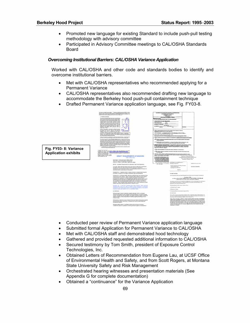
Berkeley Hood Project Status Report: 1995−2003
• Promoted new language for existing Standard to include push-pull testing methodology with advisory committee
• Participated in Advisory Committee meetings to CAL/OSHA Standards Board
Overcoming Institutional Barriers: CAL/OSHA Variance Application
Worked with CAL/OSHA and other code and standards bodies to identify and overcome institutional barriers.
• Met with CAL/OSHA representatives who recommended applying for a Permanent Variance
• CAL/OSHA representatives also recommended drafting new language to accommodate the Berkeley hood push-pull containment technique
• Drafted Permanent Variance application language, see Fig. FY03-8.
Fig. FY03- 8: Variance Application exhibits
• Conducted peer review of Permanent Variance application language • Submitted formal Application for Permanent Variance to CAL/OSHA • Met with CAL/OSHA staff and demonstrated hood technology • Gathered and provided requested additional information to CAL/OSHA • Secured testimony by Tom Smith, president of Exposure Control
Technologies, Inc. • Obtained Letters of Recommendation from Eugene Lau, at UCSF Office
of Environmental Health and Safety, and from Scott Rogers, at Montana State University Safety and Risk Management
• Orchestrated hearing witnesses and presentation materials (See Appendix G for complete documentation)
• Obtained a “continuance” for the Variance Application 69

Berkeley Hood Project Status Report: 1995−2003
• Developed request for clarification of “equivalency” for face velocity testing with experts and CAL/OSHA
• Submitted request for clarification of “what is equivalent to face velocity testing” to ANSI
• Intends to petition CAL/OSHA Board to include “new language” for push-pull testing methodology into existing Standard
Participated in Industry Forums
Participate in industry forums such as the ASHRAE lab committee TC 9.10. LBNL continued to work on SPC-110 to define and develop ASHRAE 110-1995 test procedures in preparation for the new Method to be issue in 2005. During this reporting period, a review of the latest draft document was completed. Edits and comments were forwarded to Dr. Gerhard Knutson for consideration and potential inclusion. These edits will most likely be reviewed during the upcoming annual ASHRAE meeting in Anaheim CA in 2004. LBNL is negotiating with ASHRAE to conduct both a forum and a seminar for the TC9.10 Laboratory Technical Committee at this meeting.
Institutional Barriers: Status Reports
Significant effort was spent working on institutional barriers to the Berkeley hood containment technology in FY03. The following status reports are provided on seeking a variance from CAL/OSHA to test the containment of the Berkeley hood with tracer gas methods, as provided by ASHRAE 110-1995, and on changing the existing CAL/OSHA Laboratory-type Hood ventilation standard to include an alternative tracer gas testing method to a face velocity test.
CAL/OSHA Variance Application Initial Hearing
In December 2002, a hearing was held before the CAL/OSHA Standards Board (the Board) to get a ruling on an application for a variance to operate a Berkeley hood in California (specifically at San Diego State University (SDSU)). No resolution was reached regarding an "equivalent performance indicator" to CAL/OSHA’s face velocity standard, so the Board granted a "continuance" to get additional information to support our variance application. Per the Board’s guidance, we then sought review of the "face velocity" test-approach from an organization respected by CAL/OSHA, namely ANSI (American National Standards Institute).
Interpretation Request
70
Accordingly, in February, 2003, an interpretation was requested of ANSI/AIHA regarding an “equivalent performance indicator” comparable to a face velocity test. The wording of this request was reviewed by CAL/OSHA staff and included their additional discussion topics for ANSI’s consideration. In June 2003, we received a response to the inquiry requested from ANSI/AIHA. Stated in their response; ANSI firmly "requires" a tracer gas test that ANSI considers "superior" to a face velocity test. The Berkeley hood has successfully passed many tracer gas tests.

Berkeley Hood Project Status Report: 1995−2003
Request for second hearing
Consequently, on 24 June we requested a second "continuance" hearing with the CAL/OSHA Standards Board to rule on our variance application. In early July, the CAL/OSHA Hearing Officer advised that “in order to schedule the next hearing, you must have provided the material that you initially described in your application. To discuss in more detail the specific information necessary to schedule another hearing before the Board panel, please contact Tom Mitchell [CAL/OSHA staff]…” Mitchell e-mailed the following: “…the next step in the variance application is the submittal of the ASHRAE 110 test results.”
Working with CAL/OSHA Staff
Supporting material was submitted with the application and in subsequent transmittals through December, 2002. No additional ASHRAE 110 tests are planned for the SDSU hood until Cal/OSHA approves the variance application, which includes extensive in situ testing prior to use. We understood as a result of the December hearing that the next step in the variance application process was for the Board to approve/disapprove "the alternative safety and health measures [the] applicant intends to use...", and specifically from the official CAL/OSHA application form:
The SDSU Variance Application’s plan calls for a series of ASHRAE 110-1995 tracer gas tests to ensure containment over a wide range of operating conditions.
The “Catch 22”
The key words from the application form excerpted above are “plan to use.” Our set of alternative testing measures, i.e., the applicant’s “plan”, must be approved first. Otherwise, we have no CAL/OSHA-approved basis on which to proceed.
CAL/OSHA staff has a different understanding of the procedure than ours, which is to “test” to some un-agreed upon method to some undefined goal that may result in granting a variance. This difference was discussed with Mr. Mitchell on 14 July. We could only agree that we disagreed on the steps outlined in the CAL/OSHA procedure, as written in their form. We immediately contacted CAL/OSHA’s hearing officer to help resolve the difference between our understanding and Mr. Mitchell’s. There has been no response to this phone call. We have subsequently sent several e-mails with no further response.
Barbara Steinhardt-Carter, the CAL/OSHA hearing officer, was contacted again by phone on 20 August 2003 with the following results: 1. Jere Ingram is no longer the Chairman of the CAL/OSHA Standards Board. He was
replaced a few weeks ago by a new Chairman named Steve Rank. This is a major setback for our application. We had the confidence and general support of Mr. Ingram. However, we are essentially starting over with a new person that did not experience the testimony of our expert witnesses.
71
2. She was "too busy" to go over our procedural differences with Tom Mitchell. She said she would get back on Friday, 22 August, to "discuss the issue" of our application. She did not call on Friday.

Berkeley Hood Project Status Report: 1995−2003
With no return phone call received, an e-mail was sent to Steinhardt-Carter on Monday, 25 August, summarizing our efforts to move the variance process ahead since 24 June (see above for details). We await CAL/OSHA for the following:
• to disseminate the ANSI response and other documents to the Board and other parties involved,
• to receive a letter confirming their addition to the record, • to advise the normal procedural steps of a variance application, and • to schedule the continuance hearing.
Summary
Included, below, is an excerpt for the interpretation response letter we received from ANSI/AIHA that supports our position for a performance-based test:
In summary it seems that your specific design of hood may not lend itself well to evaluation solely by face velocity tests. It is for this very reason that Section 3.3 was written from a performance-based aspect. The current document [ANSI/AIHA Z9.5-2002] indicates that containment, and not face velocity is the primary performance criteria. That is the reason additional information is provided on the right side (advisory) on containment testing. In section 3.3.2 it is stated that:
“Once adequate performance has been established for a particular hood at a given benchmark face velocity.... that benchmark face velocity shall be used for a periodic check...”
No face velocity limitations are stated in the mandatory wording. Guidance is provided in the advisory language for typical situations. Clearly, your design is not typical, and if effective containment can be demonstrated at a lower face velocity than that provided in the guidance, it would appear that this particular hood was in conformance with this aspect of ANSI/AIHA Z9.5-2003.
We feel these statements clearly rank face velocity as subordinate to tracer gas containment testing. The High Performance Fume Hood at SDSU will be operated in the push/pull mode only after it passes the ASHRAE 110-1995 tracer gas test with SF6 leakage less than 0.1 parts per million (ppm) at a gas release rate of 4 liters per minute (lpm), per the ANSI/AIHA Z9.5 standard. This is consistent with the application and the formal interpretation from ANSI/AIHA which states, “the tracer gas portion of ASHRAE 110 with an as installed performance of 4 liters per minute at 0.10 ppm is a superior test of fume hood safety and containment than simply verifying the hood as having 100 feet per minute of average face velocity.”
72

Berkeley Hood Project Status Report: 1995−2003
Changing CAL/OSHA Standard 5154.1 Advisory Committee Participation
Geoffrey Bell participates on an Advisory Committee to help Cal/OSHA review two petitions, No. 377 and No. 395, with respect to Section 5154.1, Ventilation Requirements for Laboratory-Type Hood Operations. Petition No. 395 requested revising Section 5154.1.c to be amended to entirely replace the current prescriptive face velocity requirement, for fume hood operations, with a performance test requirement, e.g., tracer gas testing. In response to initial “committee guidelines” provided by Cal/OSHA staff (Bruce Wallace), the advisory committee developed a revised Section 5154.1 that addressed Petition No. 395 by including a set of alternative performance tests that could be performed, instead of a face velocity test, as an indicator of equivalent performance. The current face velocity test method was not removed in the revised standard and could be used by a hood operator, if so desired.
Alternative Performance Test
After completing the revised Section 5154.1, which included the alternative performance test standard, the “guidelines” for the committee changed since Mr. Wallace did not agree with the revisions. He was convinced that ANSI/ASHRAE tracer gas performance tests were inadequate and less protective than the current inward face velocity standard. Influenced and undermined by this situation, disagreements ensued amongst advisory committee members that eventually lead to dropping the revised Section 5154.1 that included alternative performance tests. Therefore, at this point, Cal/OSHA is not adequately considering Petition 395.
ANSI Recommendation
While Cal/OSHA staff seems recalcitrant to evolve beyond the low-cost, easy to measure, face velocity standard, industry leaders are recognizing its limitations as an indicator of containment and, thus, safety. ANSI, who promulgated the face velocity standard originally adopted by Cal/OSHA, now strongly recommends against its sole use as a performance test. Their newly adopted standard Z9.5-2002 requires using the more meaningful, tracer gas testing (a performance test of containment). Experts have found that many hoods passing a face velocity test fail these more robust containment tests. Contemplating the merits of using tracer gas testing for measuring laboratory-type hood containment performance, worker protection is not well served by only allowing face velocity measurements as the sole performance indicator.
Public Hearing on Petitions
On 22 May 2003 a public hearing on the two petitions was held in San Diego. Comments were received regarding the proposed revisions to 5154.1. Since the Board is required to respond to these comments, the advisory committee (and other interested parties) is being reconvened. It is scheduled to meet on 17 September 2003, in Oakland. The purpose of this meeting is to discuss the comments made on the proposal, in May, and assist the Board with its analysis and response to these comments. Note that the advisory committee does not
73
Berkeley Hood Project Status Report: 1995−2003
report to the Board, it serves at the will of staff, which can accept or reject the advisory committee's input.
Slow Progress
Timing is a key issue. Cal/OSHA staff is committed to the existing standard they developed in 1976. The advisory committee met six times between 2 May 2000 and 8 August 2001, and the public hearing wasn't held until 22 May 2003. After over three years, there has been no progress adopting a performance test of fume hood containment, even as an alternative to face velocity tests.
In a conversation with the CAL/OSHA hearing officer on 20 August 2003, it was reported that Jere Ingram is no longer the Chairman of the CAL/OSHA Standards Board. He was replaced by a new Chairman named Steve Rank. This may be a setback since the new chairman will not have the background of the initial hearing and his experience and interest is unknown.
Next Steps
Depending on the outcome of the new Advisory Committee meeting scheduled for 17 September 2003, we expect to follow one of two possible courses of action subject to available funding:
1. Support modification of Petition No. 395, as noted above, to include in the Standard a set of alternative performance tests, namely ANSI/ASHRAE tracer gas tests, that could be performed, instead of a face velocity test, as an indicator of performance.
2. Submit our own petition that promotes a set of alternative performance tests, namely ANSI/ASHRAE tracer gas tests, that could be performed, instead of a face velocity test, as an indicator of performance.
Monthly DOE Reports
Monthly reports to the DOE regarding work on institutional barriers are provided in this section.
Monthly Report for October-November, 2002 1. Formulated task outline for work with standards committees that will help
overcome some of the barriers to using the Berkeley Hood (FY03 funding).
2. All DOE-supported research for FY02 completed.
3. Finalized reports (for draft reports entitled "The Berkeley Hood's Envelope of Operation: Preliminary Findings" and "Grill Profiles for the Berkeley Hood Lower Plenum") and future work is on hold until FY 03 funding arrives.
Monthly Report for December, 2002 CAL/OSHA Hearing
Supporting information and documentation relating to a fume hood Application for Permanent Variance was presented to CAL/OSHA on 4 December 2002. To
74

Berkeley Hood Project Status Report: 1995−2003
comply with this Notice, LBNL will work with CAL/OSHA staff and endeavor to further demonstrate the Berkeley hood’s ability to provide equivalent safety.
Next steps
As directed by Jere Ingram, Standards Board Chairman, LBNL continued to work with CAL/OSHA Standards Board and Staff members to resolve the issue of equivalency.
Plan of Action
A “proposed” Plan of Action was provided that listed actions to take place informally between LBNL staff and CAL/OSHA Standards Board staff. A formal hearing will be necessary at the conclusion of this Plan of Action. The focus of this Plan of Action, as discussed at the conclusion of the 4 December hearing, is to seek an interpretation from the American National Standards Institute (ANSI) regarding an equivalent performance indicator for “traditional” face velocity. This interpretation would be used to evaluate laboratory-type hoods having design features that do not use traditional face velocity as their method of containment.
Monthly Report for January, 2003 Work progressed on formulating a question that will be posed to the American National Standards Institute (ANSI) for an interpretation of statements in their Laboratory Ventilation Standard, ANSI Z9.5, as they relate to a Berkeley fume hood. Specifically, we are seeking an interpretation recommending an equivalent performance test that could be used instead of a quantified face velocity. Face velocity, which is a commonly used in evaluating conventional fume hood performance, is not a relevant criterion for determining a Berkeley hood’s ability to capture and contain contaminants.
Monthly Report for February, 2003 The question regarding an interpretation recommending an equivalent
performance test, which could be used instead of a quantified face velocity, was finally composed and formally sent to the American National Standards Institute (ANSI)/American Industrial Hygienists Association (AIHA). An agreed upon phasing was reached with input from CAL/OSHA. The interpretation process will now be monitored and expedited, as necessary. Turnaround time is projected to be 30 to 60 days by ANSI/AIHA.
The American Society of Heating, Refrigeration, and Air-Conditioning of Engineers, Inc. (ASHRAE) is in process of updating its Method of Testing Performance of Laboratory Fume Hoods, ANSI/ASHRAE 110-1995. LBNL is a member of the SPC 110 committee that is completing the update. During this reporting period, a review of the latest draft document was completed. Edits and comments were forwarded to Dr. Gerhard Knutson for consideration and potential inclusion.
Monthly Report for March, 2003 The fume hood equivalent performance question, referenced in the February
2003 monthly report, was officially received, by Jill Snyder at AIHA, and 75

Berkeley Hood Project Status Report: 1995−2003
forwarded to the appropriate committee. Lou DiBerardinis heads the ANSI/AIHA committee that will formulate a response to our interpretation question. He is in process of identifying members of the committee willing to provide input regarding the interpretation question. Continued expediting will be necessary to ensure a response by mid-May.
No additional communication has resulted with ASHRAE since providing comments on the “third” draft ANSI/ASHRAE 110-1995 Method of Testing Performance of Laboratory Fume Hoods. All SPC-110 committee member’s responses to the third draft document are due by 15 April 2003. Prior to this deadline, Dr. Gerhard Knutson will be contacted to determine if LBNL edits were considered and will be included.
Monthly Report for April, 2003 The ANSI/AIHA sub-committee chair, Lou DiBerardinis, has formulated a draft
response to LBNL’s request for an interpretation regarding the equivalency question formulated to address using face velocity as a performance indicator, which is required by CAL/OSHA. He has distributed this draft to the sub-committee members for their comments and input. Once the latest ANSI/AIHA Ventilation Standard Z9.5 – 2002 is officially published, we will get the sub-committee’s final response to the equivalency question. Continued expediting will be necessary to ensure a response by mid-May.
No additional communication has resulted with ASHRAE since providing comments on the “third” draft ANSI/ASHRAE 110-1995 Method of Testing Performance of Laboratory Fume Hoods. All SPC-110 committee member’s responses to the third draft document are due by 15 April 2003. Dr. Gerhard Knutson was contacted after this deadline to determine if LBNL edits were considered and will be included. We await his response.
Monthly Report for May, 2003 Awaiting ANSI response to interpretation of Fume Hood Test for (our) non-conventional hood. Interpretation is expected in June now that ANSI has adopted the new test standard for which we requested the interpretation.
Monthly Report for June, 2003 ANSI/AIHA has responded to LBNL’s request for an interpretation regarding the
equivalency of using another testing method instead of face velocity as a hood performance indicator, which is required by CAL/OSHA. ANSI/AIHA response was very favorable and supported LBNL’s position that tracer gas testing is equivalent and, in fact, “superior” to face velocity test methods. Accordingly, ANSI/AIHA “requires” a tracer gas test to be performed to determine a hood’s containment performance. We have sent ANSI/AIHA’s final response to the equivalency question to CAL/OSHA and have requested a hearing to present this information to the Standards Board. CAL/OSHA staff is reviewing our request to conduct this hearing.
76

Berkeley Hood Project Status Report: 1995−2003
No additional communication has resulted with ASHRAE since providing comments on the “third” draft ANSI/ASHRAE 110-1995 Method of Testing Performance of Laboratory Fume Hoods. The SPC-110 committee member’s met at the ASHRAE meeting in Kansas City. Some items of the proposed upgrade to the ASHRAE 110 document were reviewed, but LBNL edits were not considered yet. The upcoming annual meeting in Anaheim CA will most likely review these edits.
Monthly Report for July, 2003 ANSI/AIHA’s final response to the equivalency question was sent to CAL/OSHA
in June. At that time, LBNL requested a hearing to present this information to the Standards Board. CAL/OSHA staff reviewed our request to conduct this hearing, but have not scheduled the hearing. We are seeking advise from LBNL attorneys to determine how best to proceed due to CAL/OSHA staff’s insistence to alter established CAL/OSHA Variance Application procedure.
LBNL is negotiating with ASHRAE to conduct both a forum and a seminar for the TC9.10 Laboratory Technical Committee at the upcoming annual meeting in Anaheim CA in 2004.
Monthly Report for August, 2003 We sought advise from LBNL attorneys to determine how best to proceed with
the CAL/OSHA Variance Application since CAL/OSHA staff has altered the established variance procedure. LBNL attorneys were unable to help. We contacted CAL/OSHA again in July by phone and e-mail to schedule the next hearing without reply whatsoever from CAL/OSHA. We will continue to phone and e-mail. A detailed status report on applying for the variance and changing the CAL/OSHA Standard 5154.1 is available.
LBNL is continuing negotiations with ASHRAE to conduct both a forum and a seminar for the TC9.10 Laboratory Technical Committee at the upcoming annual meeting in Anaheim CA in 2004.
FY02 Accomplishments
Major accomplishments for FY02 included: updated Berkeley hood brochure, produced cost savings estimates, consulted with original inventor, and reviewed Berkeley design with industry experts.
Expert Review and Recommendations for Improved Hood Design
Leading industry experts7 evaluated Berkeley Hood prototypes and provided feedback on desirable technical improvements. These informed incremental improvements to the prototypes included in the field tests, and helped to establish future direction for research and development needs (see next section).
77
7 Dr. Gerhard Knutson, CIH (Knutson Ventilation Consulting, Inc.), Tom Smith, P.E. (ECT, Inc.), and Dale Hitchings, P.E., CIH (SAFELAB Corporation).

Berkeley Hood Project Status Report: 1995−2003
Safety Testing and Monitoring Techniques Each expert emphasized improved testing methods (for standard hoods as well as the Berkeley Hood). They noted many potential factors in real-world operating conditions (e.g. clutter within the hood; user arm motion) that are not represented in the existing test methods. Similarly, more work on failure analysis was considered necessary, discussed further below.
It was also generally recognized that there is a need for and value in improved in-situ monitoring of hood performance. This need is important in the context of overall hood commissioning and installation, as well as annual testing. Suggestions were made that consistency and accuracy be ensured by providing on-site personnel with a convenient one-point interface for data acquisition and diagnostic equipment connection. Specific points included the following, some of which have already been acted upon:
♦ Monitoring volumetric flow of the supply air system.
♦ Improving “sweep” effect along the work surface (subsequently completed).
♦ Studying Capture velocity, i.e. capture of materials outside the sash.
♦ Evaluating hoods with Pressurization tests and leakage measurements.
♦ Determining Face velocities and supply-air velocities with and without supply fans; floor sweep with supply fans on.
♦ Challenging hoods with Cross-draft tests.
♦ Evaluating Containment as a function of operator position and movement.
♦ Monitoring Two points of measurement in each supply plenum. (Accepted & done: one IR interrupt of fan blade; one velocity meter.)
♦ Within the overall topic of testing, we plan to create an annual testing protocol to include: smoke tests, supply outlet velocity, and face velocity with supply fans off. Cross drafts may also be included depending on further discussions with our fume hood testing experts.
Lastly, shortcomings of existing test equipment were identified and it was suggested, in particular, that we re-visit the tracer gas ejector design in collaboration with industry. The current design used for ASHRAE 110 tests is already deemed inappropriate, e.g. it does not produce appropriate plume shape or SF6 concentration.
Design Improvements In response to observations that the top plenum probably introduces excess air inside the hood’s interior, we reduced the size of the top plenum outlet.
78

Berkeley Hood Project Status Report: 1995−2003
We remedied concerns about a potential “lazy flow along the work surface”, i.e. slow-moving air at the hood’s interior floor, by shaping the supply air diffuser in an acute angle (less than 90 degrees) with hood floor.
All three experts recommended redesigning the hood with a single fan to supply all three plenums.
It was also suggested that we evaluate filtering the air supply. This would improve the hood’s operational reliability and, in some cases, product integrity or research productivity. The primary concern is to reduce the risk of screen clogging inside the supply plenums.
Further work was suggested to improve the user interface and ergonomics. For example, questions were raised about user acceptance of the height of the lower supply outlet grill, which is higher than a typical hood’s airfoil. It was agreed that this should be minimized and that the height would be lowered on future prototypes.8
Operational Envelope and Failure Modes It was universally agreed that more should be done to define failure modes and influences of laboratory environmental conditions such as diffuser supply-air vectors. This work was subsequently initiated. Additional specific suggestions included:
♦ Ensure the hood is not pressurized in the event of a main-exhaust failure.
♦ Study pros and cons of using house exhaust to decouple hood performance at low flow rates from the overall laboratory supply/exhaust regime, i.e. decoupling the fume hood function from the general laboratory ventilation function.
♦ Analyze damage/clogging of the screens over all supply-air outlets. At present, rigid grills are being added to protect these screens on lower plenum outlet, only.
♦ Evaluate reducing supply air through the top (inside) plenum to avoid spillage due to over-pressurizing the hood’s interior in the event of main exhaust system failure.
♦ Analyze the influence on containment by the geometry of the perforations and the lower slot dimension in back baffle.
♦ Study potential turbulence caused by sash pull-handle.
♦ Evaluate residence-time of helium bubbles and smoke to determine dead-air spots; eddy spots; etc. This could involve both empirical (field measurements) and analytical tests (CFD analysis).
79
8 It is worth noting, however, that there is a safety benefit in that it creates physical barrier (containment) of spills and makes it impossible for user to leave items near the edge of the hood opening.

Berkeley Hood Project Status Report: 1995−2003
♦ Analyze pros and cons of forward curved centrifugal fans (which can be fouled). Fans should have fan curves where flow is not strongly influenced by fouling. Consider possibility of VFDs on supply-air fans to compensate for filter loading.
♦ Standardize exhaust plenum geometry to avoid unintended mis-configuration by installers.
♦ Provide alarm if hood deviates from prescribed performance ranges. Identify relevant alarm points (flows, fan rotation, delta-p) and cost-benefit tradeoffs.
Overcoming Institutional Barriers All three experts endorsed the idea of changing the existing CAL/OSHA standards. In the interim, it would be appropriate to pursue variances for field testing and demonstrations. It was suggested that the Berkeley Hood could be defined as a local exhaust ventilation system (e.g. those used in weigh-stations or dental laboratories), rather than as general laboratory exhaust ventilation. This is probably not practical in retrofit situations and would require new test procedures
80

Berkeley Hood Project Status Report: 1995−2003
ONGOING AND FUTURE ACTIVITIES
Although the Berkeley Hood is well on its way to commercialization, numerous hurdles remain to be overcome before facility owners or designers can easily integrate this technology into their projects and before manufacturers will invest in bringing the technology to market. This section summarizes a number of public-interest activities required to bridge the gap between the present status of the Berkeley Hood and its ultimate success in the marketplace. Ongoing activity is funded in the near term by several sources (e.g. DOE, CEC, and SDSU/SDG&E), much of which is specifically targeted for field tests and demonstrations. Most of the technology development and some of the market development involves multi-year activities that are only partially funded at present.
Technology Development
Table 5 begins an overview of progress made to date and the pathway towards completion of the project and commercialization of the product. Although the Berkeley Hood is well on its way to commercialization, numerous hurdles remain to be overcome before facility owners or designers can easily integrate this technology into their projects and before manufacturers will invest in bringing the technology to market. A number of public-interest R&D activities are required to bridge the gap between the present status of the Berkeley Hood and its ultimate success in the marketplace. Based on critiques of early prototypes provided by leading industry experts, we have prepared a detailed breakdown of needed developments in Table 5.
Four main categories of work are summarized:
1. Perform Safety Testing and Improve Monitoring Techniques. Researchers are currently developing monitoring techniques, and are participating with various professional committees to improve prevailing test standards. Subsequent work needed includes development of less costly test methods and enhancement of feedback-control systems that work in conjunction with real-time monitoring. In addition to standard test methods, it is important to gain a better understanding of real-world conditions that are not evaluated by standard tests, such as the movement of people and air near the hood entry.
2. Develop Prototypes. Results from current demonstration projects and feedback from industry are providing valuable input into the evolution of the Berkeley Hood design. Wider hood- openings are more typical in practice than the four-foot format of the first-generation Berkeley Hood and wider (six- to eight-foot openings) hoods present new challenges not addressed in the current hood. Other areas remaining to be resolved are supply-air geometries to ensure that interior surfaces are “swept,” and improved interior designs (baffles, foils, plenums, fan systems) to better improve fume removal. Also important is integrating sensor-based controls to optimize energy performance and ensure safety. The significant potential for “air-divider” retrofits to existing, standard hoods should also be evaluated. Preliminary design work focusing on hood lighting has been very successful; the results should be tested in a real-world prototype mockup with user evaluation.
81

Berkeley Hood Project Status Report: 1995−2003
3. Define Operational Envelope and Failure Modes. In the broadest sense of fume hood installations in laboratory spaces, much is yet to be understood about failure modes. With respect to the Berkeley hood, valuable work includes identifying points of interior tracer gas concentration, understanding the implication of general laboratory exhaust in failures and possible control/response modes, and understanding the dynamics of multiple Berkeley Hoods simultaneously operating in the same room.
Beyond the hood itself, work is needed on the interactions with the general laboratory and HVAC system. Better understanding is needed of the effects of pressurization fluctuations and other phenomena associated with supply air diffusers, doorways, general exhaust systems, doorways, etc.
4. Conduct Side-by-side Tests with Conventional Hoods. Success in the market, including regulatory approvals and overcoming institutional barriers, will require comprehensive, comparative test data with hoods of conventional design. Many tests have been devised or proposed by experts and regulators to test the Berkeley technology without knowledge of how conventional hoods would perform under the same conditions. For example, it has been hypothesized that although the Berkeley hood performs well under static, industry standard tests, it may not perform as well under dynamic conditions. Since no standard dynamic tests are available, the Berkeley hood has been subject to many non-standard tests. In some cases the Berkeley hood performs well while in others it does not. However, it is not known how conventional hoods would perform under the same sub-optimal test conditions. To properly evaluate the technology, side-by-side tests must be run. While we expect the Berkeley hood to perform well, it is likely that it will out perform conventional hoods in some areas (e.g. containment), while under perform them in others (e.g. re-entrainment). Risk analyses will need to be studied to understand the tradeoffs.
Market Transformation
1. Perform Impact Analysis and Prepare Business Case. Although a potential for significant energy savings appears to exist, our initial energy impact analysis is highly generalized and hinges on a number of key assumptions. Improved data are needed on the overall population of hoods, current sales rates, geographical distribution, and baseline energy use of standard hoods across a range of industry and climatic settings. Improved energy analysis, coupled with cost-benefit information, should be assembled into a coherent business case. The potential for retrofit-driven savings and new market segments (e.g. wet benches) should also be identified and analyzed.
2. Identify and Overcome Institutional Barriers. Continued involvement in professional societies and with regulatory agencies is necessary. Their testing standards discriminate against the Berkeley Hood, and, thus, present significant barriers to commercialization.
3. Conduct Field Tests and Outreach, and Develop Industry Partnerships. Field tests achieve multiple goals ranging from identifying opportunities for technical improvements to proof-of-concept necessary to reduce the perceived risks for private firms seeking to ultimately commercialize the Berkeley Hood. Proving the concept is necessary to reduce any perceived risks by private firms seeking to ultimately
82

Berkeley Hood Project Status Report: 1995−2003
commercialize the Berkeley Hood. Outreach activities should include continued maintenance and development of the Berkeley Hood website, presentations, and publications in professional and popular literature. Current activities with industrial partners include working with the industry leaders to fabricate of a wider (6-foot) prototype and development improved monitoring and control systems. Continuing to protect new intellectual property and licensing the existing technology to industrial partners are clearly key needs.
83

Berkeley Hood Project Status Report: 1995−2003
Table 5. Technology development R&D and deployment needs for the Berkeley Hood.
84

Berkeley Hood Project Status Report: 1995−2003
Table 5 (cont’d)
85

Berkeley Hood Project Status Report: 1995−2003
Table 5 (cont’d)
86

Berkeley Hood Project Status Report: 1995−2003
Deployment Options
There are many complementary pathways for outreach and deployment, including:
1. Institutional and industrial field demonstrations: We have undertaken demonstrations at three universities, and we are planning to field test the technology at three industrial sites in California. Target customers include ChevronTexaco, Genentech, and Asyst Technologies. In addition, we have proposed to DOE's Energy Management Program to run field tests at two National Labs – Idaho National Energy Laboratory and the Lawrence Livermore National Laboratory. Field tests provide feedback to the development process, and increase credibility for the technology in the marketplace. Further, each of these organizations is a major user of fume hoods. As participants in these tests, they will likely become early adopters of the technology. Many users insist on small-scale in-house tests before they are willing to accept a new technology. These demonstrations will jump-start that process.
2. Federal Energy Management Program's (FEMP) New Technology Demonstration Program (NTDP) ( ):http://www.eren.doe.gov/femp/prodtech/newtechdemo.html This program assists Federal agencies in assessing new energy efficiency technologies through demonstrations and information dissemination. LBNL has participated on several NTDP projects and has already alerted FEMP to the fume hood opportunity. They are receptive to including the Berkeley high-performance hood in the program, once it is commercially available.
3. Federal Procurement Challenge ( ): http://www.eren.doe.gov/femp/procurement/ In response to congressional and administrative mandates, FEMP coordinates procurement efforts to encourage Federal agencies to purchase energy efficient products. One aspect of this program is product recommendations. Recommendations are available in hard copy as well as on-line. We have already worked with FEMP in developing a fume hood system recommendation. Once the Berkeley Hood is commercially available, it can be added to the recommendation. We have also prepared a special guide on efficient fume hoods for FEMP.
4. GSA Procurement Schedule: To facilitate buying products, vendors are able to offer products through the GSA procurement schedule. GSA attempts to highlight energy efficiency products on the schedule. We can help coordinate getting the Berkeley hood on the GSA schedule.
5. DOE's Energy Efficiency Working Group: LBNL participates with other DOE labs in exchanging information on energy efficiency opportunities. For example, it was through this group that we recruited two DOE labs for fume hood demonstrations. Information on the Berkeley Hood will be distributed to this group when it is available.
6. Laboratories for the 21st Century (Labs21)
(see http://www.epa.gov/labs21century/ ): Labs21 is a combined DOE and EPA program specifically focused on improving the energy and environmental performance of laboratories. LBNL and NREL provide technical support and
87

Berkeley Hood Project Status Report: 1995−2003
leadership to this program. The Berkeley Hood has been featured and discussed at Labs21 conferences and workshops. At a past conference in San Francisco, a prototype hood was demonstrated at a PG&E- sponsored reception. The demonstration was well attended by at least 75 laboratory professionals. No other product has received this level of attention at Labs21 events.
7. University of California: As a "campus" of the University of California, LBNL is often asked to provide technical assistance to the entire organization. We work closely with the Office of the President (UCOP) on energy-efficiency issues. Although purchasing is not centralized, they are aware of relevant projects in the system. For example, we are advising the design team for the new University of Merced campus and, more specifically, its first science building. The design team is very interested in utilizing the Berkeley Hood; however, availability/timing is an issue.
8. Utility market transformation programs: Several years ago utilities moved away from rebate programs to market transformation programs. This allowed them to take a longer-term perspective and support emerging technologies that had the potential for significant savings. Recently, two Berkeley hood demonstration projects were funded by utilities. PG&E funded a demonstration at UC San Francisco, and SDG&E is funding a demonstration at San Diego State University. We can expect continued utility assistance to bring energy-efficient fume hood technologies to their customers. In March 2000 to support PG&E's Food Service Technology Center (FSTC) in San Ramon, LBNL demonstrated a neutrally-buoyant bubble generator at the annual conference, sponsored by the FSTC. The team also delivered a presentation on the Berkeley Hood at the Flow Visualization Conference sponsored by FSTC on June 30, 2000 at the Pacific Energy Center in San Francisco.
8. Utility incentive programs: With the energy crisis in California, utilities have revamped and expanded incentive programs. LBNL can work with California utilities to include high performance fume hoods in these programs.
88

Berkeley Hood Project Status Report: 1995−2003
REFERENCES
ACGIH. 1995. Industrial Ventilation: A Manual of Recommended Practice - 22nd Edition. ISBN: 1-882417-09-7 (ACGIH). The American Conference of Governmental Industrial Hygienists, Inc., eds. Cincinnati, OH: Publisher, 1995.
Altemose, B A. , M. R. Flynn, and J. Sprankle. “Application of a Tracer Gas Challenge with a Human Subject to Investigate Factors Affecting the Performance of Laboratory Fume Hoods.” AIHA Journal: Vol. 59, No. 5, pp. 321–327, 1998. http://aiha.allenpress.com/
American Society of Heating, Refrigeration, and Air-conditioning Engineers (ASHRAE), 1991 Applications Handbook. Atlanta, GA.: ASHRAE, 1994.
Bell, G. 2002. “ASHRAE 110 Tracer Gas Report -- SDSU: Berkeley Hood; Labconco Prototype, Alpha Version – Rev. 2.” Lawrence Berkeley National Laboratory.
Bell, G.C., P.E., E. Mills, D. Sartor, D. Avery, M. Siminovitch, M.A. Piette. “A Design Guide for Energy-Efficient Research Laboratories”, LBNL-PUB-777, Lawrence Berkeley National Laboratory, Center for Building Science, Applications Team. September 1996.
Bell, G., D. Sartor, and E. Mills. “The Berkeley Hood – High Performance Fume Hood Field Test Results.” Lawrence Berkeley National Laboratory, (in preparation), 2001a.
Bell, G., D. Sartor, and E. Mills. “The Berkeley Hood – High Performance Fume Hood Field Test at UC San Francisco.” Lawrence Berkeley National Laboratory, (in preparation), 2001b.
Bell, G. and D. Sartor. “Improving Laboratory Fume-Hood Performance at Montana State University.” Lawrence Berkeley National Laboratory, Internal Report, October.
Bell, G. C. PE, D. Sartor; The Berkeley Hood: Progress Towards Industrial Demonstrations; Report for The California Energy Commission; May 2003.
Bell, G. C. PE; P. Matthes The Berkeley Hood: An Operational Envelope Study – 2002, Progress Report and Research Status for The California Energy Commission; , Test Dates: March – October 2002, Report Date: 1 May 2003.
Caplan, K.J. and G.W. Knutson. "Development of Criteria for Design, Selection and In-Place Testing of Laboratory Fume Hoods and Laboratory Ventilation Air Supply, #2438 Vol. 83 Part 1, 1977." ASHRAE Report Number 2438 RP 70, 1977.
Caplan, K.J., and Knutson, G.W., "Laboratory Fume Hoods: A Performance Test." ASHRAE Transactions, Vol. 84, Parts 1 and 2. Atlanta, GA: ASHRAE, 1978.
Chan, G. 1999. “Low-Flow Fume Hood: Baffles and Vortices.” Lawrence Berkeley National Laboratory, Student Intern Report..
Coggan, D.A.. 1997. “Avoiding Unsafe Design Practices for Laboratory Fume Hood and Pressurization Control Systems”. http://www.accent.net/coggan/miconex92.html
89

Berkeley Hood Project Status Report: 1995−2003
Cooper, E. Crawley. Laboratory Design Handbook. ISBN 0-8493-8996-8. Boca Raton, FL: CRC Press, 1994.
Feustel, H, C. Buchannan, D.J. Dickerhoff, G.C. Bell, D.A. Sartor, and E. Mills. “Development of an Energy-Efficient Laboratory Fume Hood.” Lawrence Berkeley National Laboratory, (in Preparation), 2001.
Fox, K. 2000. “Chemical Fume Hood Safety: Protecting the Health of Laboratory Workers”. Lawrence Berkeley National Laboratory, Student Intern Report.
Gadgil, A.J. D. Faulkner, W. J. Fisk. “Reduced Worker Exposure and Improved Energy Efficiency in Industrialized Fume Hoods Using an Air Vest.” Proceedings of IAQ92: Environments for People, American Society of Heating, Refrigerating and Air Conditioning Engineers, Atlanta, GA., 1992.
Griffin, M. 1999. “Low-Flow Fume Hood Project: Safety, Containment Requirements and Test Methods”. Lawrence Berkeley National Laboratory, Student Intern Report.
Hitchings, D., P.E. and K. Maupins. “Using the ASHRAE 110 Test as a TQM Tool to Improve Laboratory Fume Hood Performance.” ASHRAE Transactions: Symposia, 1997.
Hitchings, D., “Commissioning Laboratory Fume Hoods Using the ASHRAE 110-1995 Method”, 1996. http://www.safelab.com/FACT_SHEETS/FACT7/Fact7.htm
Ivany, R., E. and L. DiBerardinus. “A New Method for Quantitative, In- Use Testing of Laboratory Fume Hoods.” Am. Ind. Hyg. Assoc. J. 50:275-280. 1989.
Joao, R.V., and C.E. Violin, J. Fernandez, J. Reiman, E. Party, E.L. Gershey. “Some Fume Hood Selection and Performance Criteria.” Appendix B-10. The Rockefeller University, 1230 York Ave., New York, N.Y. 10021 or Laboratory Safety Services, Inc., 100 Oak Ridge Rd., Oak Ridge, NJ 07438, 1997.
Kjelgaard, J.M. 2001. Engineering Weather Data. McGraw-Hill. ISBN 0-07-137029-3
.Knutson, G.W. Personal communication with H. Feustel, August 7, 2001.
LBNL. 2001. Berkeley Hood Brochure, LBNL Pub 843 Rev. C., Lawrence Berkeley National Laboratory..
Mills, E., G. Bell, D. Sartor, A. Chen, D. Avery, M. Siminovitch, S. Greenberg, G. Marton, A. de Almeida, and L.E. Lock. "Energy Efficiency in California Laboratory-Type Facilities." Prepared for the California Institute for Energy Efficiency. Lawrence Berkeley, 1996. http://eetd.lbl.gov/CBS/pubs/LabEnergy/index.html
Mitchell, J., M. Siminovitch, and E. Page. “Energy-Efficient Fume-Hood Lighting”. Lawrence Berkeley National Laboratory Report. Internal report, 1999.
Monsen, R.R.. "Practical Solutions to Retrofitting Existing Fume Hoods and Laboratories." ASHRAE Transactions V. 95, Part 2, Laboratory HVAC, 1989.
90

Berkeley Hood Project Status Report: 1995−2003
Moyer R.S. and J.O. Dungan. “Turning Fume Hood Diversity into Energy Savings.” ASHRAE Transactions. 1822 – 32, 1987.
NIH, “Methodology for Optimization of Laboratory Hood Containment”, Vol. 1 & 2. National Institutes of Health, Office of Research Services, Div. Of Engineering Services, Bethesda, MD, November 1996.
Newman, V. FEMP Fume Hood Procurement Guide.
Smith, Tom. Personal communications January 2001.
Roberts, M. 1999. “Airflow through Woven Stainless Steel Mesh”. Lawrence Berkeley National Laboratory, Student Intern Report.
Ruys, T., AIA, ed. Handbook of Facilities Planning, Vol. One, Laboratory Facilities; ISBN 0-442-31852-9. New York: Van Nostrand Reinhold, 1990.
Sartor, D., G. Bell, E. Mills. 2002. “Research for Researchers.” Engineered Systems (June).
Saunders, G. T. Laboratory Fume Hoods - A User's Manual; ISBN 0-471-56935. New York, NY: John Wiley & Sons, Inc., 1993.
Shames, I.H. Mechanics of Fluids, McGraw-Hill, Chapter 11-8, p. 359, 1962.
Soule, N., G. C. Bell, PE; The Berkeley Hood: Bottom Supply Grill Study, Report for The U.S. Department of Energy; 2002.
Varley J.O. “Measuring Fume Hood Diversity in an Industrial Laboratory.” ASHRAE Transactions 99. Part 2, 1993.
Vogel, J. 1999. “Fume Hood Patent Review and Barrier Identification”. Lawrence Berkeley National Laboratory, Student Intern Report.
Weale, J., D. Sartor, and E.L. Lee. 2001. "How Low can Your Go? Low Pressure Drop Laboratory Design”. Lawrence Berkeley National Laboratory Report. Forthcoming in ASHRAE Journal.
91

Berkeley Hood Project Status Report: 1995−2003
APPENDICES
Appendix A: Project Goals and Task Development Details
Appendix B: Field Test Program Outline (Summary)
Appendix C: Field Test Program Outline (Details)
Appendix D: Press Release Describing Beginning of Field Testing
Appendix E: Montana State University Field-Test Timeline
Appendix F: Market Analysis
Appendix G: Reports by Dr. Helmut Feustel
Energy Efficient Fume Hoods (Low-Flow Fume Hoods), 1999
Task Summary and Report, 2002
Appendix H: Reports by Michael Roberts
Air Flow through Woven Stainless Steel Mesh, 1999
Plenum Characterization, 1999
Appendix I: Fume Hood Patent Review and Barrier Identification
Report by Jeff Vogel
Appendix J: Guidelines for Fume Hood Face Velocity and Testing Methods
Report by Mammie Griffin
Appendix K: Low-Flow Fume Hood: Baffles and Vortices
Report by Greg Chan, 1999
Appendix L: Chemical Fume Hood Safety
92

Berkeley Hood Project Status Report: 1995−2003
Report by Kevin Fox, 2000
Appendix M: Improving Laboratory Fume Hood Performance at Montana State University
Report by Geoffrey Bell and Dale Sartor, 2000
Appendix N: Energy Efficient Fume-Hood Lighting
Report by Jeff Michell, Dr. Michael Siminovitch, Erik Page
Appendix O: Bottom Supply Grill Study
Report by Natalie Soule, 2002
Appendix P: Operational Envelope Study - 2002
Draft Report by Geoffrey C. Bell and Peter Matthes, 2002
Appendix Q: Preliminary Evaluations: SF6 Ejector Velocity-Profile Results
Report by Geoffrey C. Bell and Michael Homer, 2000
Appendix R: Tools for ASHRAE 110-1995 Test- ITI Qualitek
Report by Wayne Huang, 2000
Appendix S: Containment Testing of the Berkeley Fume Hood
Report by Matthew Fisher, 2001
Appendix T: Reports by Ian Guthrie
Design and the Velocity Distribution of the Front Plenum of the Berkeley Hood, 2001
Further Investigation of the Velocity Distribution Across the Bottom Plenum of the Berkeley Hood, 2001
Appendix U: Transition Piece Study: Berkeley Fume Hood
Report by Keith Suda-Ciderquist, 2003
Appendix V: ASHRAE 110-1995 SF6 Tracer Gas Studies: Berkeley Fume Hood
93

Berkeley Hood Project Status Report: 1995−2003
LBNL Final Prototype hood, 2000
UCSF/Labconco Alpha hood, 2000
SDSU/Labconco Alpha hood, Rev. 2, 2001
Appendix W: California Energy Commission (CEC) Reports
High-Performance Fume Hood Field Test: Results and Research Agenda, 2002
The Berkeley Hood: Lessons Learned from Field Demonstrations, 2002
The Berkeley Hood: Progress Towards Industrial Demonstrations, 2003
Appendix X: Pacific Gas and Electric Report
High-Performance Fume Hood Field Test at the University of California, San Francisco, 2001
Appendix Y: Berkeley Fume Hood Patents
Energy Efficient Laboratory Fume Hood, 2000
Low Flow Fume Hood, 2002
Appendix Z: Berkeley Fume Hood Brochure
PUB-842, Rev. G, 2002
Appendix AA: Berkeley Fume Hood Energy Savings Estimates
Detailed California Savings Estimate, 2002
Summarized California Savings Estimate, 2002
Appendix AB: Berkeley Fume Hood Smoke Videos
Internal Large Volume Smoke Containment
Supply Smoke Demonstrating Air Divider Technology
Appendix AC: American National Standards Institute (ANSI) Z9.5 Correspondence
94

Berkeley Hood Project Status Report: 1995−2003
95
Interpretation Request, 2003
ANSI Response, 2003
Appendix AD: CAL/OSHA Variance Application Hearing Booklet