Embed Size (px)
Citation preview
The Bombay Lifts Rules, 1958 Published vide Notification No. G. N., I. & C. D. No. BLA. 1158, dated 15th October, 1958
(B.G., 1959, Part 4B, page 1) mh468
LEGISLATIVE HISTORY
In exercise of the powers conferred by section 12 of the Bombay Lifts Act, 1939 (Bombay X of 1939), and in supersession of the Bombay Lifts Rules, 1940, the Government of Bombay hereby makes the following rules, namely :- 1. Short title. - These rules may be called the Bombay Lifts Rules, 1958. 2. Definitions. - In these rules,-
(1) "Act" means the Bombay Lifts Act, 1939;
[(2) "bottom car run by" means the distance between the car buffer striker plate and
the striking surface of the buffer when the car is in level with the bottom terminal
landing;
(2A) "bottom clearance" means the clear vertical distance from the floor of the lift-
pit to the lowest structural or mechanical part, equipment or device installed
beneath the car-platform, except the guide shoes, rollers, safety jaw blocks
and platform appron or guard located within three hundred millimetres
measured horizontally from the sides of the car platform when the car rests on
its fully compressed buffers;
(2B) "bottom counterweight run-by" means the distance between the counter-weight
buffer striker plate and the striking surface of the counter weight buffer when the
car floor is in level within the top terminal landing;]
(3) "bottom over-travel means the distance provided for the car-floor to travel below
the level of the bottom lift landing when the car is stopped by the normal terminal
stopping device;
(4) "buffer" means a device designed to absorb or reduce the impact of the lift car or
a counter-weight at the extreme bottom limit of travel;
(5) "call indicator" means a device for indicating to the lift operator the lift landing
from which calls have been made;
[(5A) "car" or "lift car' means the load carrying unit with its floor or platform. Car
frame and enclosing body work;]
(6) "car appron" or "landing appron" means a protective screen attached to the
under-side of the car-platform or lift landing, as the case may be, to prevent an
object from being trapped between the car platform and the lift landing;
(7) "car enclosure" means the enclosing body work of the lift car which comprises the
sides and roof and is built upon the car platform;
(8) "car floor" or "car platform" means that part of the lift car which forms the floor
and directly supports the load;
(9) "car frame" means the supporting frame or sling to which the car platform safety
gear, guide shoes and suspension ropes are attached;
(10) "car levelling device" means an automatic device designed to cause the lift car
to move at a reduced speed within a limited zone and to stop substantially level
with the lift-landing, independently of varying loads;
(11) "car switch control" means a method of control whereby the movement of the lift
car is directly under the control of the lift operator by means of a switch in the lift
car;
(12) "compensating ropes and chains" means the ropes or chains suspended from
the car frame or counter-weight to counter balance the weight of the suspension
ropes;
(13) "contract load" means the load specified in the approved plans and Form 'A';
(14) "contract speed" means the speed specified in the approved plans and Form 'A'
and equivalent to the means of maximum speed attained by the lift in any part of
its travel in the up and down directions, with contract load in the lift-car;
(15) "control equipment" means the components of a lift by means of which motion,
direction of travel, speed and stopping are controlled;
(16) "controller" means a device or group of devices comprising the principal
components of a control equipment;
(17) "counter-weight" means a weight or series of weights to counter balance the
weight of the lift-car or part of the load thereof;
(18) "drum drive" means a method of transmitting power to the suspension ropes by
means of a winding drum;
(19) "dual control" means a method or alternative automatic or car-switch control, so
arranged that either may be used but not at the same time;
(20) "electro-mechanical brake" means a brake consisting of friction shoes applied to
a brake drum by means of springs or weights and released electrically;
(21) "emergency stop switch" means a device designed to cut off power to the
control circuit to cause the lift-car to stop;
(22) "final or ultimate limit switch" means an emergency stop switch designed to stop
the lift-car in the event of excessive over travel;
(23) "flexible guide cams safety gear" means a safety gear in which the action on the
guides is effected by means of rollers or came applied gradually in an emergency;
(24) "floor selector" means a mechanism which forms part of the control equipment
in certain automatic lifts and is designed to operate controls which cause the lift-
car to stop at the required floor;
(25) "form" means a Form appended to these rules;
(26) "gate closer" or "door closer" means a device which closes a gate or door, as
the case may be, automatically;
(27) "gate lock" or "door lock" means a lock for application to a lift-landing or lift-car
door or gate, as the case may be, and so designed that the door or gate, as the
case may be, may only be opened when the lift-car is in the landing zone or by a
special key;
(28) "gate operator" or "door operator" means a power operated device for opening
and closing gates or doors, as the case may be:
(29) "gate switch", "gate contract door" or "switch door contact" means a switch
operated by the movement of a gate or door, as the case may be;
[(29-A) "governor tripping speed" means the speed at which a lift car speed governor
trips;]
(30) "gradual wedge clamp safety gear" means a safety gear in which the action on
the guides is effected by a screw and wedge or similar device applied gradually in
an emergency;
(31) "guides" means the members used to guide the movement of the lift car or
counter weight;
(32) "guide bracket" means the part of a guide fixing which carries the guide seating
or guide clips and bolts and serves to secure them to the building or structure;
(33) "guide fixing" means an assembly of parts comprising a guide bracket carrying a
guide seating of guide clips and bolts and serving to secure a car guide or counter
weight guide to the building or structure;
(34) "guide shoes" means an attachment to the car-frame or counter weight for the
purpose of guiding the lift car or counter weight;
(35) "independent counter-weight" means a counter-weight intended to balance part
of the weight of the lift car and supported independently of the lift machine;
(36) "instantaneous safety gear" means a mechanical device in which the action on
the guides is effected by means of serrated rollers or cams applied
instantaneously in an emergency;
(37) "landing gate" or "landing door" means a hinged or sliding portion of a lift well
enclosure controlling access to the lift car at a lift landing;
(38) "landing zone" means the space between the positions not more than [38
centimetres] above and not more than [38 centimetres] below a lift-landing;
(39) "lift pit" means the space in the lift well below the level of the lowest lift landing
served;
(40) "lift well" means the unobstructed space within a lift well enclosure provided for
the vertical movement of a lift car and any counter weight including the lift pit and
the space for top clearance;
(41) "lift well enclosure" means any structure which separates the lift well from Its
surroundings;
(42) "movable floor" means a lift car floor or platform arranged to operate a switch
under the influence of the weight thereon;
(43) "normal terminal limit" means a switch arranged to open the control circuit and
to stop the lift car automatically within the limits over travel;
(44) "over speed governor" means an automatic device which brings the lift car or
counter weight to rest by operating the safety gear in the event of the speed in a
descending direction exceeding a pre-determined limit;
(45) "safety gear" means a mechanical device attached to the car frame or counter
weight to stop and to hold the lift car or counter weight to the guides in the event
of free fall or if governor operated or over speed in the descending direction;
(46) "schedule" means the Schedule appended to these rules;
(47) "section" means a section of the Act;
(48) "slack rope switch" means a device incorporating a switch used in a drum-driven
lift for automatically cutting off the power to the control circuit in case all or any of
the suspension ropes becomes slack;
[(48A) "top clearance" means the shortest vertical distance between the top of the
car crosshead or, where no car crosshead is provided, between the top of the car
and the nearest part of the overhead structure or any other obstruction when the
car floor is in level with the top terminal landing;]
(49) "top over travel" means the distance provided for the car floor to travel above
the level of the top lift landing when the lift car is stopped by the normal terminal
stepping device;
(50) "traction drive" or "V-sheave drive" means a method of transmitting power to the
suspension ropes by means of a sheave;
(51) "trailing cable" means a flexible cable providing electrical connection between
the lift car and a fixed point or points;
(52) [* * *]
(53) "travel" means the distance the bottom and top lift landings served;
(54) "winding drum" means a drum forming part of a lift machine round which the
suspension ropes are wound and to which they are attached.
3. Permission for installing lift or for making additions or alterations [and by a declaration in Form A1 from the contractor to whom the applicant proposes to entrust the work of installing the lift or, as the case may be, of additions and alterations thereto] to lift installed. - (1) Every owner of a place intending -
(i) to install a lift in such place, or
(ii) to make additions or alterations to a lift installed at such place, shall make an
application in Form 'A' to the Inspector of Lifts before any work in connection with
the installation of the lift or addition or alteration thereto is started. Every such
application shall be accompanied by two sets of plans of the installations or, as
the case may be, of the additions or alterations.
(2) On receipt of an application under sub-rule (1), the Inspector of Lifts shall, after making such inquiries and requiring the applicant to furnish such information as he may deem necessary, forward the application with his remarks to the [Chief Engineer (Electrical)], who may, thereupon, either grant or refuse the permission applied for. 4. Licence for working lift. - (1) Every owner of a place who is permitted to install a lift in such place shall, within one month after the lift is installed, deliver or send or cause to be delivered or sent to the Inspector of Lifts, notice in writing of such installation, and shall make an application to him for a licence for working the lift. The notice and the application shall be in Form 'B' [and shall be accompanied by a certificate in Form B1 from the contractor who has installed the lift.] (2) On receipt of an application under sub-rule (1) the Inspector of Lifts shall, after making such inquiries as he may deem necessary, forward the application with his remarks to the [Chief Engineer (Electrical)] who may, subject to the provisions of rule 5, either grant or refuse the licence. The licence shall be in Form 'C'. 5. Licence for working lift not to be granted unless requirements laid down in the Schedule are complied with. - No licence for working a lift shall be granted unless the requirements laid down in the Schedule have been complied with in respect of the lift and its installation. [5A. Fees for licenses. - Fees for licences for working lifts shall be paid as follows, namely
:-
Rs.
(a) For a lift driven by A.C.
electric motor
.. .. .. .. 750.00
(b) For a lift other than a
gearless lift driven by D.C.
electric motor
.. .. .. .. 1,500.00
(c) For a gearless lift .. .. .. .. 2,250.00]
6. Terms on which lifts shall be worked. - Every lift shall be worked subject to the following terms
(i) The licensee shall maintain the lift and its installation in accordance with the
requirements laid down in the Schedule to the Bombay Lifts Rules, 1958.
(ii) The licensee shall forthwith report to the Inspector of Lifts any defect in the
working of the lift.

(iii) The licensee shall not carry out any additions or alternations to a lift installation
without obtaining permission in that behalf from the Inspector of Lifts as required
by the provisions of section 7 A and rule 3.
(iv) The licensee shall not use or cause the lift to be used which is not in a safe
working condition.
[(v) Unless the licensee, in the opinion of the Inspector of Lifts, has suitable means
for the satisfactory maintenance of the lift, the licensee shall entrust the
maintenance of the lift and its installation either to an approved manufacturer of
lifts or an approved agent of such manufacturer of lifts or to an approved firm or
company of electrical and mechanical engineers of at least five years standing.]
Explanation. - For the purposes of this clause, 'approved' means approved by the [Chief Engineer (Electrical.]
(vi) Every person, firm or company entrusted with the maintenance of the lift and its
installation under clause (v) shall properly actuate all the safety devices while the
lifts is in use and report to the owner of the lift immediately any defect found in the
installation.
(vii) If any part, enclosure, gate or fastening of a lift is damaged or broken, the
licensee shall immediately repair and put it in good working order. He shall keep
the safety gears in good order and all parts of the lift and safety gear clean and
free from rubbish, dust or dirt. The licensee shall not weld any broken or damaged
parts which are subject to tension, torsion or bending or parts on which the lift-car
is supported.
(viii) The licensee shall forthwith replace all controlling, lifting and balance weight
ropes which indicate excessive wear, splintering, standing or bunching.
(ix) The licensee shall enter every repair and alteration to the lift in a log book which
shall be maintained in each lift installation.
(x) The licensee shall remedy every fault in the lift installation reported by the lift
operator, immediately.
(xi) The licensee shall see that the following work is carried out by his contractor at
least once a month and the result entered in the log book by the contractor,
namely :-
(i) Cleaning and lubricating the guides,
(ii) Examining the ropes and their attachments,
(iii) Examining the safety devices,
(iv) Examining and lubricating the door locks,
(v) Lubricating all moving parts,
(vi) Examining the worm and the gear.
(xii) Whenever the lift is out of order, the licensee shall see that all the landing gates
or doors are securely locked and the users of the lift are informed by a notice
posted at any conspicuous place at each floor that the lift is out of order.
(xiii) No person shall wilfully interfere with any mechanism of the lift installation.
(xiv) No person below the age of 18 years shall be engaged as a lift operator. The lift
operator shall be a person who is mentally and physically fit and trained in the
correct operation of the lift.
7. Form of notice and order under section 8. - The notice to be given under sub-section (1) of section 8 shall be in Form 'D' and the order to be issued under sub-section (2) of section 8 shall be in Form 'E'. 8. Report of accidents. - Notice of accident required to be given under section 9 shall be in Form 'F'. Such notice shall be given within 24 hours of the occurrence of the accident. 9. Unused lifts. - When a lift installed at any place ceases to be used as such, the owner shall either remove it or maintain it in safe mechanical condition after disconnecting it entirely from the electric supply. All gates and doors shall be securely locked so as to prevent the entry of unauthorised persons to the lift-well. [9A. Fees for Inspection of Lifts. - Annual fees for the inspection of lifts shall be paid
either prior to inspection or within ten days from the date of inspection as follows, namely :-]
Rs.
(a) For a lift driven by A.C. electric motor
.. .. .. .. 300.00
(b) For a lift other than a gearless lift driven by D.C. electric motor
.. .. .. .. 450.00
(c) For a gearless lift .. .. .. .. 750.00
[9B. Manner of payment of fees under rules 5A and 9A. - The fees payable under rules
5A and 9A shall be paid,-
(a) into the Government Treasury or the Reserve Bank of India to the credit of the
Electrical Department by Chalan in triplicate, the receipted duplicate being
forwarded to the Inspector of Lifts by the Treasury Officer direct; or
(b) at the office of the Inspector of Lifts in cash or by money order or cheque.]
10. Saving. - Notwithstanding the supersession of the Bombay Lifts Rules, 1940, any permission granted or licence issued or any order made, or anything done or any action taken under those rules, shall be deemed to have been granted, issued made, done or taken under the corresponding provisions of these rules.
Schedule
(See rule 5)
1. Lift-wells. - (a) All lift-wells intended for the reception of lifts shall be exclusively reserved for that purpose and shall not be used for any other purpose.
(b) Lift-wells and all equipments and apparatuses fixed therein shall be rendered fire
proof to the greatest possible extent.
(c) The inner surface of the lift-well and its enclosure facing any lift-car entrance
shall, so far as practicable, be kept smooth and flush devoid of projections or
recesses. Where any projections or tops of the recesses cannot be rendered
flush, they shall be levelled on the underside to an angle of not less than 60
degrees from the horizontal, by means of metal plates, cement rendering or other
fire-resisting materials.
(d) Where a lift-car levelling device is operative with the lift-car gate open such
interior surfaces shall always form a smooth and flush surface below each landing
level.
(e) Sufficient space shall be provided between the guides for the car and the side
walls or the lift-well enclosure to allow safe and easy access to the parts of the
safety gear for their maintenance and repairs.
(f) In the case of a lift-well which is common to more than one lift and where the lift-
car or the counter-weight of one lift is working in juxtaposition to the lift-car or the
counter-weight of another lift, such lift-cars or counter-weights shall be guarded
carefully and adequately in order to protect persons working in the lift well or on
the lift-cars from accidental contact with such cars or counter-weights in any part
of their travel.
(g) In case of a completely, enclosed lift-well a notice with the word 'Lift' shall be
placed on the outside of each landing door.
2. Lift-well enclosure. - (a) Lift-wells and wells for the counter-weight if located independently of the lift-well shall be adequately protected by means of suitable enclosure work which shall be extended on all sides from floor to ceiling.
(b) In all counter-weight wells located Independently of the main lift-well, suitable
access shall be provided for the inspection, maintenance and repairs to counter-
weight, wire ropes and their anchorages, guides and guide supports.
(c) All such doors giving access to such counter-weight wells shall be provided with
electro-mechanical devices.
(d) Where wire grill or similar construction is used, the mesh or opening shall be not
greater than [32mm.] and the lift way enclosure shall be of sufficient strength to
resist accidental impacts from users of the staircase or adjoining floors.
(e) Where the clearance between the lift-well enclosures, if of an open type, and any
moving or movable part of the lift equipment or apparatus is less than [5 cm.], the
openings in the enclosure shall be further protected by nettings of square mesh
not greater than [12mm.] and of wire not smaller than [20 Standard Wire Gauge
1mm. dia.].
(f) No counter-weight shall be allowed to travel in any lift-well or part of any life-well
other than that to which it belongs.
[(g) On every passenger lift, there shall be provided at each floor, a floor position
indicator or "IN USE" indicator or direction call registering light.]
(h) Glass shall not be used for lift-well enclosure.
[(i) The distance between the lift-well enclosure on the sides facing any lift-car
entrance and the sill edge shall be not more than 30mm. in the landing zone
below the landing gate. If such distance is more than 30mm., in the lift-well
enclosure, the same shall be finished with suitable and smooth plaster work or
facia plates so as to make the surface thereof devoid of all projections and
recesses. In case the enclosure wall on the sides facing the lift-car entrance is
more than 13 cms. from the sill edge of the lift-car platform, the lift-car door of
such lift shall be provided with means to prevent it from being opened except
when the lift-car is at the landing served by such car entrance.]
(j) The distance between the edge of any landing sill and the sill of the car platform
shall not be more than [25 mm.].
(k) No automatic fire door or shutter which operates by means of a fusible link or
otherwise due to the action of heat, shall be allowed in any landing, opening or the
lift-way enclosure of any lift, if such opening gives access to any exit from the
building.
[(l) The walls enclosing lift-well in the buildings having height more than 24 metres
shall have fire resistance of not less than two hours. The lift-well shall have
permanent vents immediately under the machine room not less than 0.2 sq. m. in
clear area.
(m) The lift-well for fire lift (a lift to enable fire brigade personnel to get to the upper
floors with the minimum delay and to be used exclusively by firemen in an
emergency and directly accessible to every landing on every floor), in the building
having more than 24 metres height, shall be segregated from the other lift-wells by
means of brick masonry or R. C. C. wall of a fire resistance of not less than two
hours.].
3. Lift-pits. - (a) Lift-pits shall be soundly constructed and maintained in a dry and clean condition. Where necessary, provision shall be made for permanent drainage.
[(b) No room, passage or thoroughfare shall be provided under any lift well :
Provided that, where it is absolutely necessary to provide any room, passage or thoroughfare
under a lift well, or the following requirements shall be fulfilled, namely :-
(i) spring or oil buffers shall be provided for lift and counter-weight;
(ii) the lift-pit shall be made sufficiently strong to withstand successfully the impact of the lift-car with the rated load or the impact of the counter-weight when descending at the rated speed or at the governor tripping speed; and
(iii) the car and the counter-weight shall be provided with a governor-operated safety gear.]
[4 (a) Top car clearance. - The top car clearance shall not be less than the sum of the
following four items, namely :-
(i) the bottom counterweight run-by;
(ii) the stroke of the counterweight buffer used;
(iii) 60 cm. or the distance which any sheave or any other equipment mounted in or on, cross-head projects above the top of the cross-head, whichever is greater; and
(iv) One half of the gravity stopping distance based on -
(A) One hundred and fifteen per cent, of the rated speed, where oil buffers are used and no provision is made to prevent the jump of the car at counterweight buffer engagement; and
(B) governor tripping speed, where spring buffers are used.
Note. - The gravity stopping distance based on the gravity retardation from any initial velocity may be calculated according to the following formula, namely :-
"S = 5.1 V2"
Where 'S' is free fall in cm. (gravity stopping distance) and 'V' is initial velocity in meters per second.
(b) Bottom car clearance. - When the car rests on its fully compressed buffer,
there shall be a vertical clearance of not less than 60 cm. between the floor of
the lift-pit and the buffer striker plates or the lowest structural or mechanical
part, equipment or device installed beneath the car platform, except the guide
shoes, rollers, safety jaw blocks and platform appron or guard located within
three hundred millimeters measured horizontally from the sides of the car
platform when the car rests on its fully compressed buffers;
When the car rests on its fully compressed buffer, no part of the car or any equipment
attached thereto shall strike any part of the lift-pit or any part of the equipment located
therein.
(c) Top counterweight clearance. - The top counterweight clearance shall not
be less than the sum of the following four items, namely :-
(i) the bottom car run-by;
(ii) the stroke of the car buffer used;
(iii) 15 cm.; and
(iv) one half the gravity stopping distance based on -
(A) one hundred and fifteen per cent, of the rated speed, where oil buffers are used and no provision is made to prevent jump of counterweight or car buffer engagement; and
(B) governor tripping speed, where spring buffers are used.
(d) Projection on lift car. - When the lift-car cross-head is 60 centimeters from the
nearest obstruction above it, no projection on the lift-car shall strike any part of the
overhead structures.]
5. Landing gates and doors. - (a) All landing openings shall be protected by gates or doors which shall extend the full height and full width of the landing openings. These openings shall in no case be less than [68 cm.] clear in width when the gates or doors are fully opened.
(b) All landing gates shall be at least [2 m.] clear in height and the top tract of the
gate or door shall not obstruct the entrance to the lift-car. They shall be, if

collapsible, of a close picket type and no openings exceeding [6 cm.] in width shall
be permitted between pickets or verticals when the gate is fully extended.
[(c) The landing gates shall be securely fixed.
(d) Where the landing door consists of two or more panels, the space between
the panel nearest to the sill edge of the landing floor and the lift-car door shall
not exceed 13 centimeters; and where the landing door is a swing door, the
distance between such door and the lift-car door shall not exceed 7.5
centimeters.
(e) The distance between the sill edge of the lift-car and the sill edge of the landing
floor shall not exceed 30 millimeters.]
(f) The openings for the landing gates or doors shall not be wider than the lift-car.
(g) The landing gates or doors which are self-closing shall be equipped with safety
devices preventing injury by trapping persons while entering or leaving the lift-car.
(h) All landing gates and door and their tracts shall be capable of withstanding a
thrust of [34 kg.] applied normally at any point excepting the vision panels, without
causing permanent deformation or without being sprung from their guides.
[(i) (a) Where the landing doors are solid and are manually operated and no
indicators are provided either near the landing door or in-side the lift-car, each of
such doors shall be provided with a vision panel.
(b) Where the vision panel is provided with glass, such glass shall be fire-resistant and safety-wired.
(c) Any projection on or recess (including vision panels) in any sliding door shall be kept to the minimum so as to avoid finger trapping between the sliding part of the door and any fixed part of any structure.]
[(j) For the lifts in buildings having height of more than 24 metres,-
(i) the landing doors shall have fire resistance of not less than one hour; and
(ii) the landing door for fire lifts shall be power operated, automatic closing and opening type, and the words 'FIRE LIFT' shall conspicuously be displayed in radium paint on lift landing doors on each floor :]
[Provided that, the requirement that the landing door for fire lifts should be power-operated, automatic closing and opening type,, and the words "FIRE LIFT" shall conspicuously be displayed in radium paint on Lift Landing doors on each floor, may be relaxed by Government in case of goods-cum-passenger lifts designed to operate at contract load of 1500 kilograms and above.] 6. Locking devices for landing gates and doors. - (a) Every landing gate or door shall be fitted with an electro-mechanical device which shall comply with the appropriate requirements given hereafter.
(b) (i) It should not be possible to open the landing gate or door from the landing side
until the lift-car is within that particular, landing zone. Provision shall be made for
the opening of the gate or door in case of emergency by means of a special key,
which shall be kept in a secure position.
(ii) It should not be possible to start the lift-car or keep it in motion unless all the landing gates or doors are locked in closed position.
Exception. - Where lift-car levelling device is provided, it is permitted to move the lift-car with the lift-car and landing gates or doors open within the landing zone.
Note. - The door shall be considered closed and the lift car may be moved away from the landings when the door is
within [58 mm.] of the jamb, or in the case of centre opening doors, when these are within [58 mm.] of each other, provided an approved attachment is fitted which will effectively prevent the doors from being reopened after they have reached a limit of [58 mm.], and provided also that the door closer is of such a type as will eventually carry the door or doors to and lock it or them in the closed position.
(iii) The electrical and mechanical parts of all locking devices shall be of substantial design and construction. The removal of any inspection cover or covers shall not affect the operation of a device. All locking devices shall be fixed securely to the enclosure by suitable means.
(iv) The locking devices for landing gates or doors shall be so designed that the lock contact is not closed until the gate or door is locked.
(v) Any springs used in the locking device shall be in compression and properly supported.
(vi) The contacts of the locking device shall be of solid and sturdy construction and shall be opened positively and the functioning of the interlock to prevent movement of the lift-car shall not be solely dependent on the action of a spring or springs nor solely upon gravity, nor upon the closing of an electric circuit.
(vii) The design shall be such that reasonable wear and tear of working parts shall not create an unsafe condition or permit of interference with the operation of the lift by movement of the gate or door or its fittings.
(viii)The conduct carrying the conductors to the lock or contract boxes shall be fixed securely to the boxes and shall maintain electrical and mechanical continuity.
(ix) The locking device together with the actuating rods or levers shall be protected from interference from the landing side of the lift-well enclosure.
(x) Provision shall be made on all lifts for device to prevent the opening of any landing gate or door while the lift-car is passing through a landing zone to another floor.
7. Lift-cars. - (a) Lift-cars shall be enclosed on all sides by means of the cage body, gates or doors and such enclosures shall be at least [2 m.], clear in height and sufficiently strong to withstand a thrust of at least 75 lbs. applied normally at any point without deformation and it shall be so secured to the car-floor and lift-car frame that it cannot work loose or become displaced in ordinary service. There shall be provided a roof solid or perforated capable of supporting a weight of a man weighing [68 kg.]. Any perforation in the roof shall reject a [25 mm.] diameter sphere.
[(b) Glass shall not be used in a lift-car except for the following purposes, namely :-
(i) covers for certificates,
(ii) lighting fixtures,
(iii) appliances used in connection with the operation of the car,
(iv) for vision panels and mirrors.
Where the glass used for any of the said purposes is more than 930 square centimetres in
dimension, it shall be of laminated type.
(b-i) Where the Inspector of Lifts is satisfied that glass to be used is for a capsule-
type lift-car and it is specially designed for fire-resistance and is of fully
transparent limanated type, he may relax the provisions of clause (b), subject to
such conditions as he may specify;]
(c) Every lift shall be provided with an alarm signal operated by a push button which
shall be fixed in a conspicuous position in the lift-car and clearly marked. The
alarm shall be wired from electric mains other than the lift mains and shall be
clearly audible outside the lift-well in order to obtain assistance in case of a break-
down or failure between the floors.
(d) Every lift installation controlled by an operator shall be operated by a removable
handle or key which shall remain at all times in the possession of the operator.
The handle or key shall automatically return to the off position and lock there
automatically when pressure is removed.
(e) Every lift-car should be provided with a light to give sufficient illumination on the
floor and such light shall be left burning during the whole time the lift is available
for use. Such light shall be on a circuit independent of the lift circuits and the
controlling switch for the light shall be in the machine room close to the main
switch for the machine.
(f) The approach to the landing gate on each floor shall be kept lighted during the
whole time the lift is available for use at night, and during the day time, if so
required by the Inspector of Lifts.
(g) Lift-cars having solid enclosure and doors and lift-cars installed in totally enclosed
lift-wells shall be provided with adequate ventilation by means of an electric fan
which shall be connected on electric mains other than the lift mains and shall
always be maintained in working condition.
(h) A door or gate shall be provided at each entrance of the lift-car. Such doors or
gates shall guard the full height and width of the lift-car opening and shall be
sufficiently strong to withstand a thrust of [34 kg.] applied normally at any point
without permanent deformation and without their being sprung from their guides.
Where gates are used they shall be of close picket type and no openings
exceeding [6 cm.] in width shall be permitted between the verticals when the gate
is fully extended.
(i) Each door or gate shall be provided with an electric switch which shall prevent the
lift-car from being started or kept in motion unless the door or gate is properly
closed. Such switches shall be opened positively when the door or gate is
opened.
Note. - This requirement prohibits the practice of short circuiting the lift-car door or gate switch to enable an
unoccupied lift-car of an automatically operated lift to be called at a landing with the lift-car door or gate open.
(j) [* * *]
(k) [* * *]
(l) Lift-car platforms shall be of framed construction and shall be designed on the
basis of contract load evenly distributed. Platforms for goods car shall be
designed to suit the particular conditions of loading. The minimum factor of safety
shall be 5 for steel and 8 for timber.
(m) Every lift-car shall be provided with an emergency exit which shall be fitted into
the roof of the car in case where one lift operates in the lift-well or where more
than one lift is installed in a lift-well, it shall be provided in the side adjacent to the
adjoining lift-car. Where conditions will not allow the provision of an emergency
exit, the safety-gear shall be of a type that can be released by hoisting up the lift-
car.
(n) Top exits shall open outwards and shall be clear of all gear or equipment
mounted on top of the lift-car.
(o) All emergency exit doors or panels shall be provided with an electric switch to
prevent the lift from being operated when doors or panels are opened or removed.
(p) A plug socket shall be provided on top of the lift-car for a hand-lamp for use by
persons working thereon.
(q) When lift-car levelling devices are used, aprons shall be fitted to the car-floor to
ensure that no space is permitted between the threshold and the landing whilst
the lift-car is being levelled to a floor.
[(r) For the lifts in buildings having height of more than 24 metres,-
(i) Lift-car for fire lift shall have floor area of not less than 1.4 square metres. It shall also have loading capacity of not less than 545 kgs. (3 persons);
(ii) lift car door shall have fire resistance of one hour;
(iii) lift-car for fire lift shall have power operated automatic closing and opening doors synchronised with landing doors while at landing level :]
[Provided that, the requirement in paragraph (iii), may be relaxed by Government in case of goods-cum-passenger lifts designed to operate at contract load of 1500 kilograms and above.] 8. Lift-car frame. - (a) Every lift-car shall be carried in a complete frame of steel girders which shall be sufficiently rigid to withstand the operation of the safety gear without permanent deformation.
(b) The factor of safety of the component parts of the lift-car frame and their
connections shall be not less than 5 based on the ultimate strength of the material
and the static load imposed on them.
(c) Renewable guide shoes or guide shoes with renewable linings shall be provided
at the top and bottom of both sides of the lift-car frame.
9. Lift-car capacity. - The contract load in relation to the lift-car floor area shall not be less than the figures shown in graphs 1 and 1A. 10. Load to be marked. - In lift-cars (a) There shall be marked conspicuously in every lift-car the maximum number of persons (calculated at [68 kg.] per person) which it can safely carry. Persons in excess of the said limit shall not be carried in the lift-car.

(b) For goods lift the load shall be given in pounds and also in persons calculated
at [68 kg.] per person.
11. Counter-weights. - (a) All counter-weights shall travel in rigid steel guides.
(b) If two counter-weights travel in the same guides, the lift car counterweight shall
be above the machine counter-weight and the clearance between them shall not
be less than [20 cm.]. Where the ropes of the machine counter-weight pass
through the lift-car counter-weight they shall be covered or protected by metal or
other suitable sleeves. Such sleeves shall have "belled" ends and be firmly
attached to the suspension ropes, and be not less than [15 cm.] longer than the
lift-car counter-weight.
(c) If an independent counter weight is used, it shall not be of such a weight as to
cause undue slackening of any of the suspension ropes during acceleration or
retardation.
(d) All counter-weight section shall be carried in a structural steel frame and shall be
secured by at least two tie rods passing through holes in all the sections. [The
factor of safety of each frame member and its connection with other frame
members shall not be less than -]
(i) 5, where the member is wrought iron and steel, and
(ii) 40, where the frame member is of cast iron.
(e) the travel-way of the counter-weight in the lift-pit shall be protected by means of a
suitable enclosure work up to a height of [2 m.] from the floor of the pit :
[Provided that, a gap of 30 centimeters or upto the top of the counterweigh buffer, whichever is higher, may be kept from the floor of the pit.] 12. Guides. - (a) The guides for the lift-car and the counter-weight, shall be rigid and shall be of steel except where the nature of the processes carried on in the building renders such material unsuitable due to acid-fumes or similar causes.
[(b) In case of lifts working at a speed exceeding 0.4 meter per second, special "Lift
T section Guides" only shall be used and they shall be joined by means of
machined spigot and socket joints or other adequate means.]
(c) Guides shall be continuous throughout the entire length of the lift-well, and shall
be provided with adequate iron or steel brackets or equivalent fixing of such
design and spacing so that the guides shall not deflect more than [6 mm.] under
normal operation.
(d) If the guides are attached to overhanging stairs, the method of fixing shall be
such that no vertical stress is transferred from the guides to the stairs.
(e) Guides shall be of such length that it will not be possible for any of the car or
counter-weight guide shoes to run off guides.
(f) Guide brackets and shims if any shall be of steel and shall not be directly
supported and fastened to the lift-well enclosure wall unless such wall is of such
construction and strength as to adequately withstand the thrust imposed on the

guides under all conditions of the lift-service. The fastenings shall be by means of
bond blocks built into the wall or expansion bolts or through bolts with metal plates
of such thickness and size as to adequately distribute the load on the wall.
(g) Guides and their fixing shall withstand the application of the safety gear when
stopping a fully loaded lift-car or the counter-weight if provided with a safety gear.
13. Buffers. - [(a) Buffers of spring or oil shall be fitted under the lift-car directly or on the floor of the lift-pit with suitable concrete or steel foundation; Provided that, oil resistant rubber buffers may be used with lifts having a contract speed not exceeding 0.25 meter per second.]
(b) Buffers shall be of such design and construction as to be able to absorb within
the limits of their stroke the whole of the kinetic energy of the lift-car carrying its
rated load when the speed of impact is the maximum running speed.
[(c) Spring or oil buffers shall be used with lifts having a rated speed upto 1.5 meters
per second. Oil buffers shall be used with lifts having a rated speed in excess of
1.5 meters per second.]
(d) Springs for the buffers shall be so designed that they will not take a permanent
set, upon absorbing the energy of the fully loaded lift-car at governor tripping
speed.
(e) Oil buffers or their equivalent shall be used with lifts having a contract speed in
excess of [91 m.] per minute.
(f) The maximum rate of retardation of oil buffers, based on governor tripping speed.
Shall not be in excess of [24.54 m.] per second i.e., 2.5 times gravity retardation.
[(g) The factor of safety of the combined suspension ropes shall not be less than the
following, namely :-
Rope speed in
metres
Factor of safety
Upto 2 metres
per second
.. .. .. .. 10
3.5 metres per
second
.. .. .. .. 11
7 metres per
second
.. .. .. .. 12
The factor of safety shall be based on static contract load plus the weight of the lift-car and
accessories in the case of traction type drive. In the drum type drive machines, the factor of
safety shall be calculated with dynamic conditions.]
(h) Oil buffers shall be provided with a device for determining easily the amount of oil
in them.
(i) Buffers shall be placed symmetrically with respect to the centre of gravity of the
lift-car and shall be so arranged that the lift-car in normal circumstances of
operation cannot strike them,

(j) Buffers shall be fitted under the counter-weight similar to those specified for lift-car
arranged symmetrically below the weight.
14. Suspension ropes. - (a) Chain shall not be used for the suspension of a lift-car. Not less than three independent suspension ropes shall be used for the lift-car or counter-weight of any lift with traction drive, and not less than two independent ropes with drum drive.
(b) Each suspension rope shall be separately and independently fixed to the car and
to the counter-weight. The simple suspension of the lift-car or the counter-weight
by means of a sheave or the like shall count as one suspension only.
(c) All ropes anchored to a winding drum shall have not less than one and one half
turns of the ropes on the winding drum when the lift-car or counter-weight has
reached the extreme limit of its over-travel.
(d) The winding drum end of the lift-car and counter-weight ropes shall be secured
by clamps on the inside of the drum.
(e) Every lift-car or counter-weight rope shall be in one length and free from joints.
(f) The materials, quality, construction and fixing of ropes shall, so far as is
applicable, conform to the appropriate British Standard Specification.
(g) The factor of safety of the combined suspension ropes shall be not less than 12,
based on static contract load, plus the weight of the lift-car and accessories.
(h) The lift-car and counter-weight ends of the suspension ropes shall be fastened by
spliced return loops, clipped return loops or individual tapered babbitted sockets.
Loops shall not bear directly on their fixings, but shall be lined with proper
thimbles, eyes or equal protection. In all cases, the fastenings shall be capable of
sustaining a load of not less than 80 per cent, of the ultimate strength of the
undisturbed rope.
(i) Means shall be provided for adjusting the lengths of the ropes to equalise the load
of the individual suspension ropes. No equaliser shall be used unless the
equaliser and its fastenings, in its several parts and assembly, have a strength of
at least 10 per cent, in excess of the strength of the cable required by sub-clause
(h).
(j) Tensioning devices for compensating ropes, governor ropes and the like shall be
protected against damage due to falling objects.
15. Emergency Safety Devices. - (a) Every lift shall be provided with a lift-car safety gear, attached to the lift-car frame and placed beneath the car-platform. The safety gear shall be capable of stopping and sustaining the lift-car with full contract load in the lift car.
(b) The application of the safety gear shall not cause the car-platform to become out
of level in excess of [6 mm.] per foot measured in any direction.
(c) No safety gear shall be permitted to stop an ascending lift-car or counter-weight,
if an ascending lift-car is to be stopped on account of overspeed, a safety gear
shall be fitted to the counter-weight for this purpose. The governor may, however,
open the motor circuit and apply the brake in the event of overspeed in the
ascending direction.
(d) When the safety gear is applied, no decrease in the tension of any rope for
applying the safety gear, or motion of the lift-car in the descending direction shall
release the safety gear. It is permissible to release the safety gear by reversing
the direction of the lift machine.
(e) When a safety gear comes into operation, it shall automatically open the
operating circuit, and it shall be possible for a reasonable person to release the
safety gear after a thorough inspection of the equipment and the taking of
necessary precautions.
(f) The safety gear shall operate to stop and sustain the lift-car in the event of failure
of the suspension ropes, or in the event of the lift exceeding a predetermined
maximum speed in the descending direction when a speed governor is fitted.
(g) Every safety gear shall operate positively and mechanically, independently of any
springs used in its construction.
(h) Any levers or dogs operated by shafts shall be keyed to such shafts by [clause 18
of Indian Standard Specification No. 4666-1968] keys or fixed by some other
equally secure device approved by the Inspector of Lifts.
(i) The design of the safety gear shall provide for its application to both guides and to
each side of such guides equally.
(j) Any rope used for applying the safety gear shall be led over independent pulleys
running on independent shafts and properly guarded. Such ropes shall be not less
than [6 mm.] in diameter and shall be of steel or phosphor bronze.
(k) It shall not be possible for vibrations of the lift-car frame to cause the safety gear
to be applied.
(l) Any part of a safety gear subject to tension, torsion or bending shall be made of
steel.
(m) All bearings for drums and screw shafts in connection with the safety gears shall
be of non-ferrous metals.
[(n) Car and counter weight safety devices shall be actuated by separate governor.
Provision shall be made to cause the application of the counterweight safety gear
at not more than 10 per cent, in excess of that at which the lift-car safety gear
applies.]
(o) The types of safety gear shall be of the following kinds, namely :-
(i) Instantaneous type limited to speed not exceeding 200 feet per minute (Type I).
(ii) Gradual wedge clamp type with gradual increasing retarding force (G.W.C.)

(iii) Flexible guide clamp type with constant retarding force (F.G.C.).
[(iv) Combination of instantaneous and oil buffer safety for speed not exceeding 2.5 metres per second.]
[(p) Safety gears designed to stop the lift-car or counterweight in a distance related
to the car or counter-weight speed shall stop the lift-car with rated load or the
counterweight from the governor tripping speed within the range of stopping
distances given in the Table below.
Explanation. - For the purpose of this sub-clause "the stopping distance" means the actual
slide as observed from the markings on the guides made by the safety gear.
Table
Serial
No.
Governor
tripping
speed in
metres per
second
Stopping distance in
millimetre
Minimum Maximum
1 0.88 368 161
2 1.00 401 173
3 1.25 482 202
4 1.5 582 237
5 1.75 700 278
6 2.00 836 326
7 2.25 990 380
8 2.5 1162 441
Note. - The following formula shall be used to determine the maximum stopping distances for gradual wedge clamp
and flexible guide clamp type safeties for lift-car and counterweight for all intermediate speeds
S 1 = 245V2 + 256
S 2 = 51V2 + 122
In this formula, 'S1' represents the maximum stopping distance in millimetres 'S2' represents the minimum stopping distance in millimetres and 'V' represents Governor tripping speeds in metres per second.
(q) The rope attached to any safety gear actuating drum shall have not less than two
turns of rope remaining on the drum after the safety jaws have gripped the guides
and stopped the lift-car.]
(r) No safety gear shall depend on the completion or maintenance of electric circuit
for its operation. All safety gears shall be applied mechanically.
(s) The gripping surfaces of lift-car or counterweight safety gears shall not be used to
guide the lift-car or counterweight but shall run free of the guides during normal
operation of the lift.
Note. - A pawl or ratched shall not be held to constitute a sufficient safety gear for lifts travelling in a vertical or substantially vertical direction.
16. Overspeed Governor. - (a) Every lift having a travel exceeding [5.5 m.] shall be equipped with an overspeed governor device which will operate to apply the safety gear in the event of the speed of the lift-car in the descending direction exceeding a predetermined limit.
(b) The governor shall be placed where it is easily accessible and where it cannot be
struck by the lift-car in case of over travel and where there is sufficient space for
the full movement or the governor parts.
(c) Governor ropes shall be not less than [8 mm.] inches in diameter and shall be of
steel or phosphor bronze and of suitable construction.
(d) The arc of contact made by the governor rope and the governor sheave shall, in
conjunction with the rope tension device, provide sufficient tractive effort to cause
proper operation of the governor.
(e) Governor ropes shall run clear of the governor jaws during the normal operation
of the lift.
(f) Governor jaws and their mountings shall be so designed that any cutting, tearing
or deformation of the rope resulting from their application shall not prevent proper
operation of the safety gear.
(g) The motor control circuit and the brake control circuit shall be opened before the
governor trips.
[(h) Governors for car safety gears shall be adjusted to actuate the safety gear at the
following speed
(i) For rated speed of 1 meter per second or less, governor tripping speed shall be 140 per cent, of the rated speed or 0.88 meter per second, whichever is higher. For the rated speed of above 1 meter per second, the maximum governor tripping speed shall be 115 per cent, of the rated speed plus 0.25 meter per second.
(ii) The minimum governor tripping speed shall be 115 per cent, of the rated speed.]
17. Slack Rope Switch. - (a) All lifts, having winding drum machines, shall be equipped with an effective slack rope switch which will cut off the power and stop the machine if the lift-car is obstructed in its travel in the descending direction.
(b) Slack-rope switches shall be so constructed that they will not automatically reset
when the slack in the ropes is removed.
(c) Live parts of the slack-rope switches shall be enclosed to prevent accidental
contact.
18. Machine rooms and overhead structure. - (a) The lift machine controller and all other apparatus and equipment of a lift installation, excepting such apparatus and equipment as functions in the lift-well or other position shall be placed in the machine room.
(b) The machine room shall be so designed as to allow free and easy access to all
parts of the equipment and the width of clear space around the machine shall in
no case be less than [60 cm.]. Provision shall be made to allow the removal and
replacements of various units.
(c) The machine room floor shall be designed and constructed to carry safely at any
point the heaviest part of the equipment and if the floor does not extend to the
enclosing wall the open sides shall be adequately guarded by suitable means.
(d) The height of the machine room shall be sufficient to allow any portion of the
equipment to be accessible and removable for repairs and replacement and shall
not be less than [1.98 m.] clear from the floor or the platform of machine
whichever is higher.
(e) The machine room shall be provided with easy and safe access which shall be
permanent and direct from the top lift landing. The entrance door shall be of
sufficient opening to allow for the removal and replacements of parts of the
machinery therein.
(f) The machine room shall be soundly constructed and shall be weather proof. It
shall be ventilated effectively to prevent undue rise in the temperature of the room.
It shall be provided with sufficient artificial illumination and at least one plug socket
point. The switch for the light shall be fixed near the entrance of the machine
room.
(g) The machine room shall be locked and shall be accessible only to those who are
concerned with the operation and maintenance of the machinery or equipment.
When the electrical pressure used is above 250 volts C. D. or 125 volts A. C., a
danger notice shall be displayed permanently on the outside of the door and near
the machinery.
(h) The machine room shall not be used as a store room or for any purpose other
than for housing the machinery connected with the lift installation.
(i) The machine room shall be provided with an insulated portable hand lamp with
workshop flexible for examining the machinery.
19. Overhead pulleys. - The place in which overhead pulleys, overspeed governors and similar machinery are fixed shall have a clear height of at least [120 cm.] and shall be easily accessible for maintenance and repair purposes. It shall be lighted adequately and shall be provided with a substantial floor or staging, spacious enough to enable maintenance and repairs to be carried out in safety. In cases where the floor or staging does not extend to the full area of the lift-well, a guard rail or its equivalent shall be provided. 20. Machine Supports. - (a) All machines, pulleys, overspeed governors and similar units shall be supported and held to prevent any unit from becoming loose or displaced. Supporting beams shall be of steel or reinforced concrete.
(b) The load on overhead beams and their supports shall be calculated as follows :-
(i) The total load on overhead beams shall be assumed as equal to all equipment resting on the beams plus twice the maximum load suspended from the beams.
(ii) The factor of safety for all overhead beams and supports based on the ultimate strength of the material and the load in accordance with paragraph (i) shall be not less than the following :-

For steel ....................... = 5
For reinforced concrete
....................... = 7
(c) The deflection of the overhead beams under the maximum static load calculated
in accordance with sub-section (i) shall not exceed 1/1,500 of the span.
(d) Wood shall not be used for structural frame work of any lift.
21. Lift Machines. - (a) No friction gearing and clutch mechanism shall be used for connecting the main gear to the hoisting drum or sheaves.
(b) No belt or chain driven machine shall be used to raise the lift-car. No worm gear
having cast iron teeth shall be employed.
(c) Every lift machine shall be equipped with brakes which shall be mechanically
applied when the operating device is in the off position or when power is cut off
from any cause. It springs are used they shall be of substantial size and
construction and shall work in compression only.
(d) Electric lift machines shall be provided with brakes released electrically.
(e) No brake shall be released in normal operation until power has been applied to
the motor.
(f) Any emergency release device fitted to a break shall not be capable of holding the
brake in the "off" position during normal operation.
(g) No signal earth fault, short circuit or couner E.M.F. shall prevent the break from
being applied during normal operation.
[(h) Fire lifts in a building having more than 24 metres height, shall work at or above
the speed of 1.0 metre/Sec. so as to reach the top floor from ground level within
one minute:]
[Provided that, this requirement may be relaxed by Government in case of goods-cum-passenger lifts designed to operate at contract load of 1500 kilograms and above.] 22. Sheaves and drums (a) All sheaves and leading pulleys shall preferably be of disconstruction. If spoke construction is used, spokes shall be of sufficient cross-section and properly stiffend.
(b) The diameter of the drum or sheave and the diverter pulleys shall be in
accordance with the term of [clause 17 of Indian Standard Specifications No.
4666-1968] current edition.
(c) Where the driving sheave or drum is connected through worm gear, the worm
gear shall be of non-reversible type.
(d) The strength of spur and worm gear shall be in accordance with [Indian Standard
Specifications 4460 and Indian Standard Specifications 3734 of
1966] respectively.
(e) Drums, sheaves and pulleys shall be of cast iron steel and shall have machined
rope grooves and be provided with suitable flanges.
(f) The sheave, drum, wor wheel or spur gear of any lift machine shall be fixed to its
shaft or driving unit by one of the following methods :-
(i) Sunk keys in accordance with [clause 18 of Indian Standard Specifications No. 4666-1968.]
(ii) Splines in accordance with B. S.S. 46, Part 2 (current edition).
(iii) Secured to a flange forming an integral part of the shaft or driving unit by means of turned tight-fitting bolts.
(g) No set screw fastenings shall be used in lieu of keys or other positive
connections.
(h) The motor of each lift machine or the worm shaft shall be so between as to
provide hand winding facilities and shall be suitably marked for the direction of up
and down travel of the lift car.
23. Shafts. - (a) Any shaft carrying a sheave or pulley and fitted between dead eyes or other housing shall be stepped, i.e., reduced in diameter at or near the point of entry at each end.
(b) Anywhere stepped shall be turned to a reasonable radius at the point of reduction
in diameter.
24. Controllers. - (a) Where gravity or spring-opened contractors having metal to metal contracts are employed to open a main circuit to stop a lift machine, such circuit shall have at least two independent breaks.
(b) Each lift machine operated a Polyphase A. C. Motor shall be protected against
phase reversal or phase failure. This shall not apply to A. C. Motors used in motor
generator sets.
(c) The installation of condensers, the operation or failure of which will cause an
unsafe condition, shall be prohibited.
(d) Provision of emergency stop switches for short-circuiting the landing lock circuit is
prohibited.
(e) All control circuits shall be fused, or otherwise protected against faults or
overload, independently of the main circuits.
(f) The voltage of any controller operating circuits shall not exceed low pressure as
defined in the Indian Electricity Rules, 1937.
(g) Controllers, operated by hand-ropes, levers or similar devices shall not be
permitted.
25. Operation and Operating Device. - (a) A manually operated main disconnecting switch shall be installed in the main circuit cables of electric lift machines or motor generator sets. The switch shall be placed close to and visible from the machine or motor-generator set it controls.
(b) With D. C. power supplies, the disconnecting switch and any circuit breaker shall
be so arranged that the brake circuit is opened at the same time that the main
circuit is opened.
(c) The interruption of the electrical circuit shall stop or shall prevent the movement
of the car.
(d) No control shall depend upon the completion or maintenance of an electric circuit
for -
(i) the interruption of the power supply to the motor and the application of the brake to stop the lift-car at terminal landings or to stop the lift-car when the emergency stop switch is operated;
(ii) the operation of the safety gear ;
Provided that, this requirement does not apply to dynamic breaking or to speed control devices.
(e) Control circuit shall be so arranged that an earth fault or open circuit shall not
create an unsafe condition.
(f) Automatic (push button operated) lifts shall conform to the following requirements
:-
(i) [* * *]
(ii) Automatic lifts which travel at a speed over [0.75m./sec.] per minute shall automatically slow down to a speed of [0.75m./sec.] per minute when making a stop at any landing.
(iii) In the case of an automatic lift, no operation of a spring nor the completion of another electric circuit shall be depended upon to break the circuit to stop the lift at terminal landings.
(iv) The landing push buttons shall be inoperative during the whole time an occupied lift-car is in use. The landing push buttons shall remain inoperative until the person or persons using the lift have vacated the lift-car and the landing gear or door has been again close, except that in cases where a preselector circuit is used, the push buttons may be utilised for this purpose, provided they do not in any way interfere with the direction of the current journey and that a time lag is provided to regulate the restarting of the lift-car.
(v) If a movable floor construction is used in the lift-car the entire floor within the car enclosure shall be movable and shall operate when a weight of [14 kg.] is placed upon it at any point.
(vi) No handrail or seat shall be fitted in the lift-car with movable floor construction.
[(g)) Every automatically controlled lift-car and every lift-car having a lift-car levelling
device shall be provided with emergency stopping device operated by a push
buttons switch in the car and it shall be clearly marked in red.]
(h) An emergency stop switch, of manually opened and closed type, shall be
provided on the top of every lift-car and in the lift pit and shall be marked
conspicuously.
(i) Drum drive machine shall not be used for speeds exceeding [0.5 m./ sec.] per
minute.
(j) All lifts travelling at a speed of [1 m./sec.] per minute and over shall be provided
with an approved floor levelling device.
(k) Signal bells or similar apparatus which can be operated from any floor in
conjunction with an indicator in the lift-car, shall be provided on all lifts operated by
lift operators.
(l) When more than one operating device is used in a lift-car, the operating devices
shall be so interlocked that only one device is effective at a time.
[(m) The operation of the fire lift in building having more than 24 metres height, shall
be a simple toggle or two button switch situated in a glass fronted box adjacent to
the lift at entrance level on ground floor. When the switch is 'ON', the landing call
points shall become inoperative and car shall report to the ground floor and the
same shall remain on car control only. When the switch is 'OFF', the lift shall
return to normal working.]
26. Electric wiring. - (a) All wiring in connection with the lift installation shall be installed in accordance with the rules and regulations made under the Indian Electricity Act, 1910, and the rules and regulations of the Bombay Fire Insurance Association, and metallic covering shall be used to protect all cables wherever possible.
(b) All training cables shall be of flexible construction and shall comply with the
specifications laid down in the regulations of the [Bombay Fire Insurance
Association and Provisions of Indian Electricity Rules, 1956],
(c) Circuits which supply current to the motor shall not be included in any twin or
multi-core trailing cable used in connection with the control and safety devices.
(d) A trailing cable which incorporates conductors for the control circuit shall be
separate and distinct from that which incorporates conductors for lighting and
signalling circuits.
[(e) The electric supply for the lifts shall be on separate circuits from the main switch
rooms and shall be taken through armoured cable separately through respective
lift shafts. The route of the armoured cable shall be safe from fire.]
27. Terminal limit Switches. - (a) Every electric lift shall be provided with upper and lower terminal limit switches arranged to stop the car automatically within the top and bottom over travels from any speed attained in normal operation. Such limit switches are to act independently of the operating device, the ultimate or final limit switches and the buffers.
(b) Terminal topping limit switches may be fitted to the lift-car, in the lift-well, or in the
machine room, and such switches shall be brought into operation by the
movement of the lift-car.
(c) The contacts of all terminal limit switches shall be opened positively and
mechanically by the movement of the lift-car.
(d) When terminal switches are situated in the machine room, they shall be mounted
on and operated by stopping device mechanically connected to and driven by the
lift-car without dependence upon friction as a driving means. An automatic safety
switch shall be provided which will stop the machine should the tape, chain, rope
or other similar device, mechanically connecting the stopping device to the car fail
:
Provided that, when the floor controlling or selector of an automatically operated lift is driven in accordance with this requirement, the floor stopping contacts for each terminal floor may serve as a normal terminal floor stopping devices. 28. Ultimate or Final Limit Switches. - (a) Electric lifts shall, in all cases, be provided with ultimate or final limit switches arranged to stop the lift-car automatically within the top and bottom clearances independently of the normal operating device and the terminal limit switches, but with the buffers operative. The switches and the oil buffer shall be so arranged that the opening of the switch and the engagement of the buffer shall be as nearly simultaneous as is possible. When spring buffers are employed, the switch shall open before the buffers are engaged.
(b) Ultimate or final limit switches shall act to prevent movement of the lift-car under
power, in both directions of travel and shall, after operating, remain open until the
lift-car has been moved by hand winding to a position within the limits of normal
travel.
(c) Ultimate or final limit switches shall be operated by the movement of the lift-car in
the lift-well; they shall not be mounted on the lift-car.
(d) Every lift having drum machine shall have two final limit switches, one being
operated by the machine and the other by the movement of the lift-car.
(e) Ultimate or final limit switches shall not control the same relay switches on the
controller as the terminal limit switches unless two or more separate and
independent relay switches on the controller are provided, two of which shall be
closed to complete the motor and brake circuit in each direction of travel. When
the ultimate or final limit switches control the same relay switch or switches on the
controller as the operating device, or the terminal limit switches, they shall be
connected in the control circuit on opposite sides to the terminal limit switches.
(f) Ultimate limit switches designed to open the main circuit of the motor may control
the same switch or switches on the controller as the terminal limit switches, but
when such ultimate limit switches are employed on direct current power supplies,
they shall be provided with additional contacts to control the brake circuit.
(g) The contacts of all final or ultimate limit switches shall be opened positively and
mechanically by the movement of the lift-car. The cam or cams for operating the
limit switches shall be of metal.
(h) The terminal and the ultimate or final limit switches shall be held in open position
when the lift-car is in contact with the overhead structure or resting on the fully
compressed buffers.
29. Tests. - (a) A contract load test of each new lift shall be made by the Engineer, who is entrusted with the work of installing the lift, in the presence of the Inspector of Lifts, before such lift is put into service for normal and regular operations. This test shall be
made to determine whether the machinery and safety gear will operate satisfactorily within the specified limits with full load in the lift-car.
(b) The brakes, limit switches, buffers, safety gears or gears and speed governor if
fitted, shall be made to function during the test, and the electrical wiring and
connections shall be tested for earthing insulation resistance and general
soundness.
(c) In the case of traction drive lifts, it shall be ascertained by a trial descent with 1½
times the full load whether the friction between the ropes and the sheave is
sufficient.
(d) The runway test shall be made with all electrical apparatus operative, except for
the overspeed contact or cut-out on the governor. For lifts operating directly from
alternating current the governor shall be tripped by hand at the maximum speed
obtainable.
(e) At each subsequent inspection the safety gear shall be tested with the lift-car
stationary and the lift-car shall be lowered to ensure that the safety gear functions
correctly.
(f) The insulation of the electrical parts of all operating and similar devices shall be
tested to withstand an alternating test-voltage equal to 10 times the working
voltage for one minute, with a maximum of 2,000 volts, applied between contacts
or similar parts, in the open position and between such contracts and earthed
parts.
30. Notices. - In case of automatic lifts the following notices shall be placed in conspicuous position in the lift-car and no other notices shall be fixed in the lift-car :-
(i) The lift shall not be used by more than ............ persons.
(ii) On entering or leaving the lift-car, close properly the landing gate and the car-
gate.
(iii) Do not open the lift-car when the lift-car is moving. The gate should only be
opened after the lift-car has stopped opposite a landing gate.
(iv) In case of danger, press the alarm button, but leave the lift-car gate closed. Wait
inside until the lift-car is brought opposite a landing, and do not attempt to leave
the lift-car until the landing gate is opened fully.
(v) Children under 12 years of age shall not use the lift unless accompanied by an
adult.
Form A
(See rule 3)
Application for permission to install Lift or for making additions or alterations to Lift installed
(To be submitted to the Inspector of Lifts, Bombay, Public Works Departments, Bombay).
(To be filled in English)
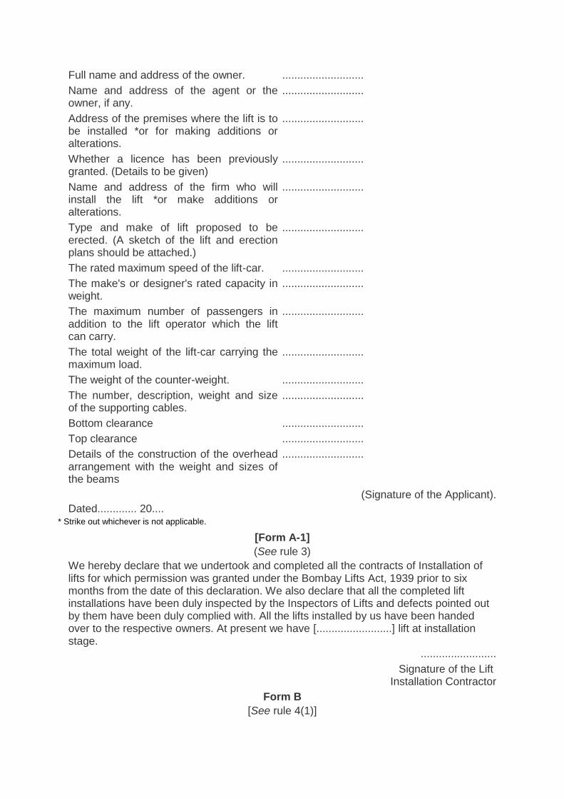
Full name and address of the owner. ...........................
Name and address of the agent or the owner, if any.
...........................
Address of the premises where the lift is to be installed *or for making additions or alterations.
...........................
Whether a licence has been previously granted. (Details to be given)
...........................
Name and address of the firm who will install the lift *or make additions or alterations.
...........................
Type and make of lift proposed to be erected. (A sketch of the lift and erection plans should be attached.)
...........................
The rated maximum speed of the lift-car. ...........................
The make's or designer's rated capacity in weight.
...........................
The maximum number of passengers in addition to the lift operator which the lift can carry.
...........................
The total weight of the lift-car carrying the maximum load.
...........................
The weight of the counter-weight. ...........................
The number, description, weight and size of the supporting cables.
...........................
Bottom clearance ...........................
Top clearance ...........................
Details of the construction of the overhead arrangement with the weight and sizes of the beams
...........................
(Signature of the Applicant).
Dated............. 20.... * Strike out whichever is not applicable.
[Form A-1]
(See rule 3)
We hereby declare that we undertook and completed all the contracts of Installation of lifts for which permission was granted under the Bombay Lifts Act, 1939 prior to six months from the date of this declaration. We also declare that all the completed lift installations have been duly inspected by the Inspectors of Lifts and defects pointed out by them have been duly complied with. All the lifts installed by us have been handed over to the respective owners. At present we have [.........................] lift at installation stage.
.........................
Signature of the Lift Installation Contractor
Form B
[See rule 4(1)]
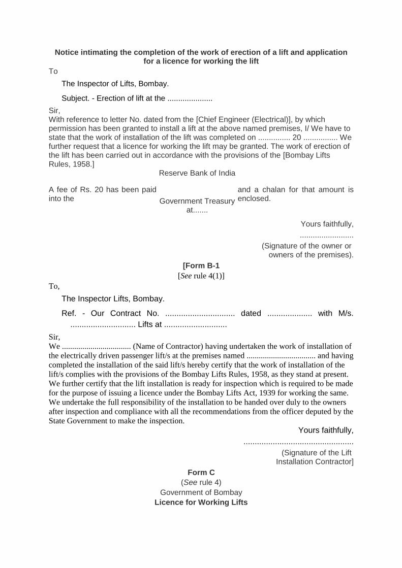
Notice intimating the completion of the work of erection of a lift and application for a licence for working the lift
To
The Inspector of Lifts, Bombay.
Subject. - Erection of lift at the .....................
Sir, With reference to letter No. dated from the [Chief Engineer (Electrical)], by which permission has been granted to install a lift at the above named premises, I/ We have to state that the work of installation of the lift was completed on ............... 20 ................ We further request that a licence for working the lift may be granted. The work of erection of the lift has been carried out in accordance with the provisions of the [Bombay Lifts Rules, 1958.]
A fee of Rs. 20 has been paid into the
Reserve Bank of India
Government Treasury at.......
and a chalan for that amount is enclosed.
Yours faithfully,
.........................
(Signature of the owner or owners of the premises).
[Form B-1
[See rule 4(1)]
To,
The Inspector Lifts, Bombay.
Ref. - Our Contract No. ............................... dated .................... with M/s.
............................. Lifts at ............................
Sir,
We .................................. (Name of Contractor) having undertaken the work of installation of
the electrically driven passenger lift/s at the premises named .................................. and having
completed the installation of the said lift/s hereby certify that the work of installation of the
lift/s complies with the provisions of the Bombay Lifts Rules, 1958, as they stand at present.
We further certify that the lift installation is ready for inspection which is required to be made
for the purpose of issuing a licence under the Bombay Lifts Act, 1939 for working the same.
We undertake the full responsibility of the installation to be handed over duly to the owners
after inspection and compliance with all the recommendations from the officer deputed by the
State Government to make the inspection.
Yours faithfully,
.................................................
(Signature of the Lift Installation Contractor]
Form C
(See rule 4)
Government of Bombay
Licence for Working Lifts
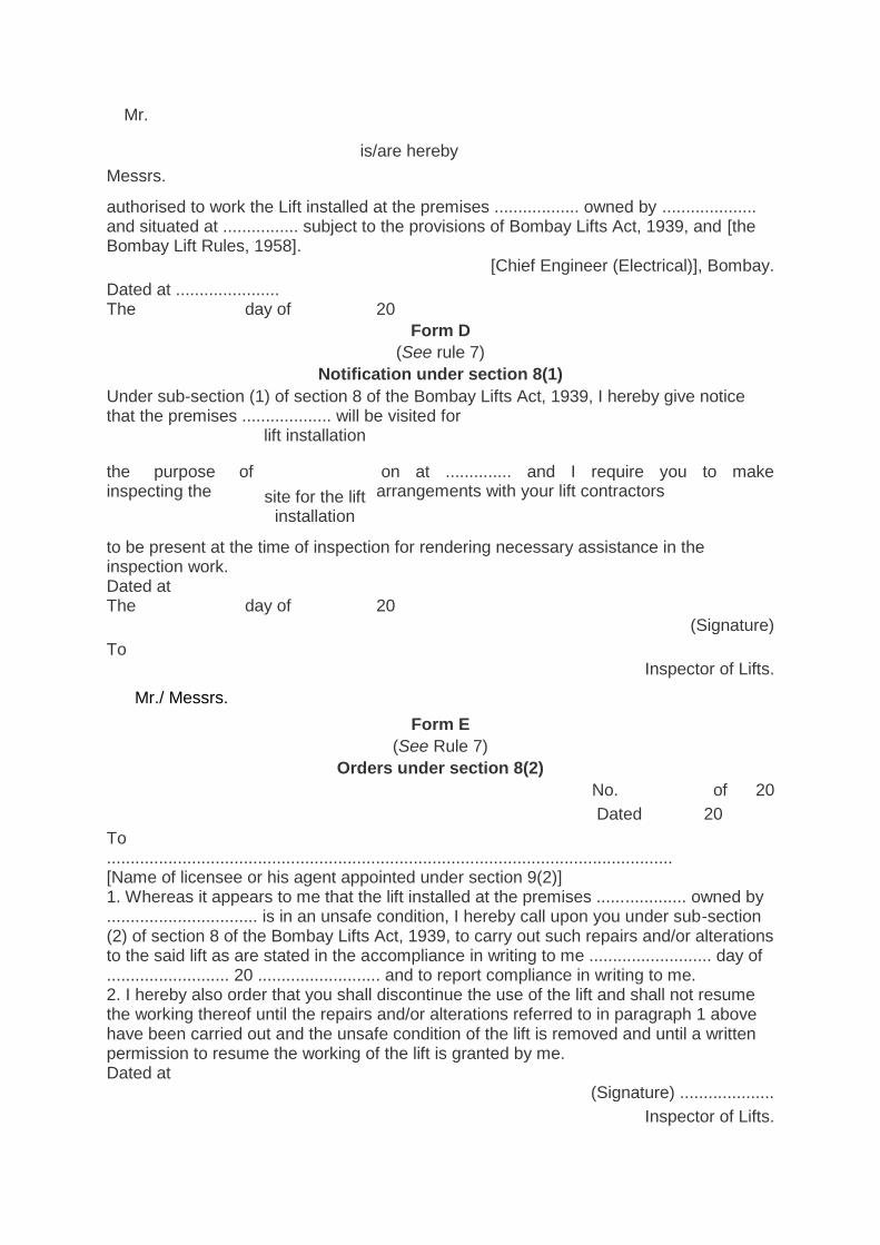
Mr.
Messrs.
is/are hereby
authorised to work the Lift installed at the premises .................. owned by .................... and situated at ................ subject to the provisions of Bombay Lifts Act, 1939, and [the Bombay Lift Rules, 1958].
[Chief Engineer (Electrical)], Bombay.
Dated at ...................... The day of 20
Form D
(See rule 7)
Notification under section 8(1)
Under sub-section (1) of section 8 of the Bombay Lifts Act, 1939, I hereby give notice that the premises ................... will be visited for
the purpose of inspecting the
lift installation
site for the lift installation
on at .............. and I require you to make arrangements with your lift contractors
to be present at the time of inspection for rendering necessary assistance in the inspection work. Dated at The day of 20
(Signature)
To Inspector of Lifts.
Mr./ Messrs.
Form E
(See Rule 7)
Orders under section 8(2)
No. of 20
Dated 20
To ........................................................................................................................ [Name of licensee or his agent appointed under section 9(2)] 1. Whereas it appears to me that the lift installed at the premises ................... owned by ................................ is in an unsafe condition, I hereby call upon you under sub-section (2) of section 8 of the Bombay Lifts Act, 1939, to carry out such repairs and/or alterations to the said lift as are stated in the accompliance in writing to me .......................... day of .......................... 20 .......................... and to report compliance in writing to me. 2. I hereby also order that you shall discontinue the use of the lift and shall not resume the working thereof until the repairs and/or alterations referred to in paragraph 1 above have been carried out and the unsafe condition of the lift is removed and until a written permission to resume the working of the lift is granted by me. Dated at
(Signature) ....................
Inspector of Lifts.
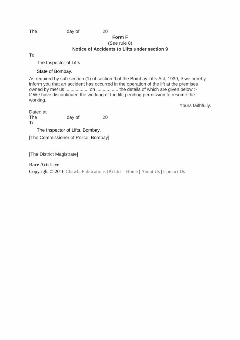
The day of 20
Form F
(See rule 8)
Notice of Accidents to Lifts under section 9
To
The Inspector of Lifts
State of Bombay.
As required by sub-section (1) of section 9 of the Bombay Lifts Act, 1939, I/ we hereby inform you that an accident has occurred in the operation of the lift at the premises owned by me/ us .................. on ................. the details of which are given below :- I/ We have discontinued the working of the lift, pending permission to resume the working.
Yours faithfully.
Dated at The day of 20 To
The Inspector of Lifts, Bombay.
[The Commissioner of Police, Bombay]
[The District Magistrate]
Bare Acts Live
Copyright © 2016 Chawla Publications (P) Ltd. - Home | About Us | Contact Us
![THE MAHARASHTRA STAMP ACT*...[THE MAHARASHTRA STAMP ACT] BOMBAY ACT No.LX OF 1958 1 This Act received the assent of the President on 4th June 1958, and assent was first published in](https://img.pdfslide.net/doc/110x75/60056a78a7511c582771a8ec/the-maharashtra-stamp-act-the-maharashtra-stamp-act-bombay-act-nolx-of-1958.jpg)


![THE BOMBAY STAMP ACT - igrmaharashtra.gov.inigrmaharashtra.gov.in/writedata/PDF/THE BOMBAY STAMP ACT.pdf · THE BOMBAY STAMP ACT, 1958 [BOMBAY ACT No. ,LX OF 1958]1 This Act received](https://img.pdfslide.net/doc/110x75/5a7552807f8b9aa3618c5c0b/the-bombay-stamp-act-bombay-stamp-actpdf-the-bombay-stamp-act-1958-bombay.jpg)


![THE BOMBAY STAMP ACT - igrmaharashtra.gov.in2012-5-24 · THE BOMBAY STAMP ACT, 1958 [BOMBAY ACT No. ,LX OF 1958]1 This Act received the assent of the President on 4th June 1958,](https://img.pdfslide.net/doc/110x75/610c90153b76c11aac4c8648/the-bombay-stamp-act-aathe-bombay-stamp-act-1958-bombay-act-no-lx-of-19581.jpg)


![INDEX [] · Amendments to the Bombay Stamp Act, 1958 – Recommendations of Bombay Chamber of Commerce and Industry Bombay Chamber of Commerce and Industry](https://img.pdfslide.net/doc/110x75/5b68f7c77f8b9a23188d5bd9/index-amendments-to-the-bombay-stamp-act-1958-recommendations-of-bombay.jpg)