Embed Size (px)
Citation preview
The C-141 StarLifter
Some assembly required
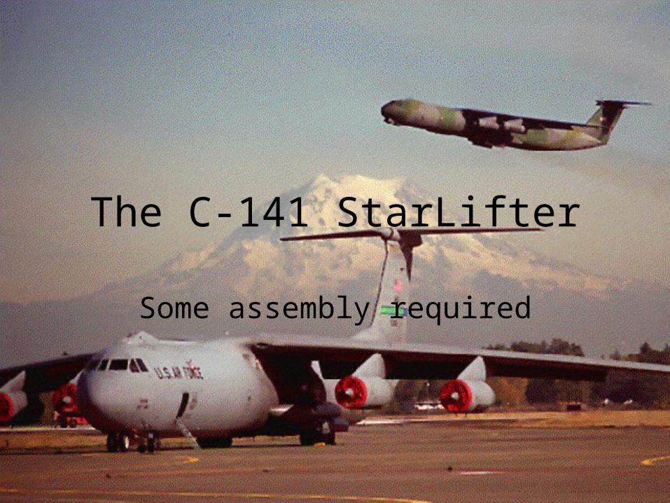
This is some of the tooling used to manufacture the C-141.
These were used to shape the sides of the fuselage.
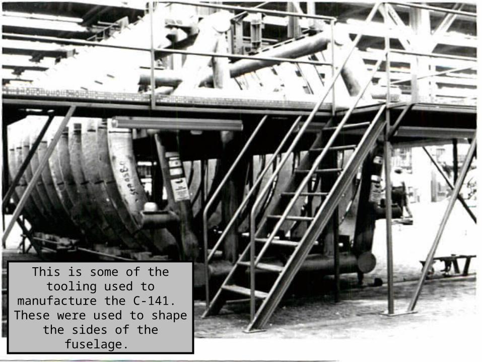
In this picture you can see the aluminum skin being applied to the segment.
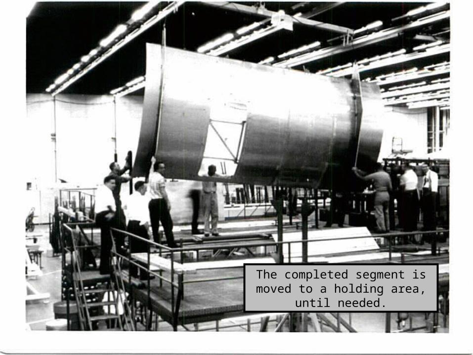
The completed segment is moved to a holding area, until needed.
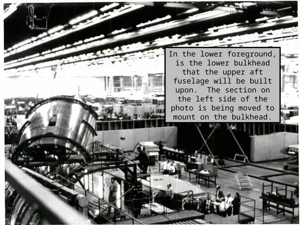
In the lower foreground, is the lower bulkhead that the upper aft fuselage will be built upon. The
section on the left side of the photo is being moved to mount
on the bulkhead.
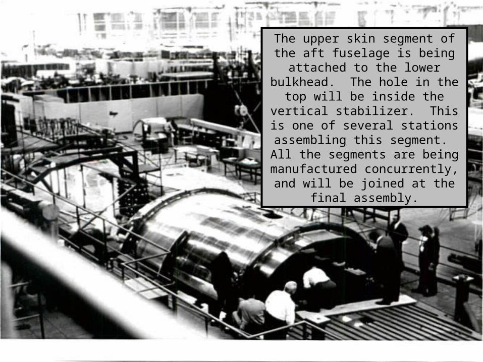
The upper skin segment of the aft fuselage is being attached to the
lower bulkhead. The hole in the top will be inside the vertical stabilizer.
This is one of several stations assembling this segment. All the segments are being manufactured concurrently, and will be joined at
the final assembly.
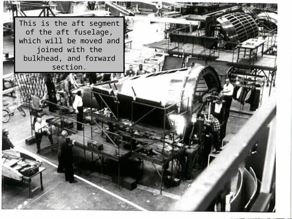
This is the aft segment of the aft fuselage, which will be moved and joined with the
bulkhead, and forward section.
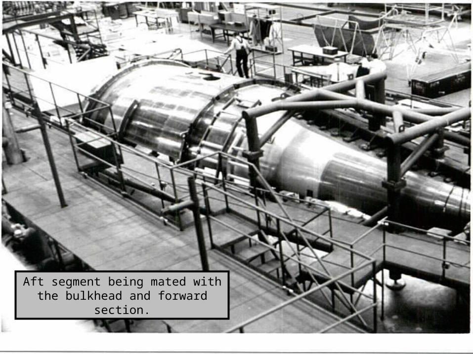
Aft segment being mated with the bulkhead and forward section.
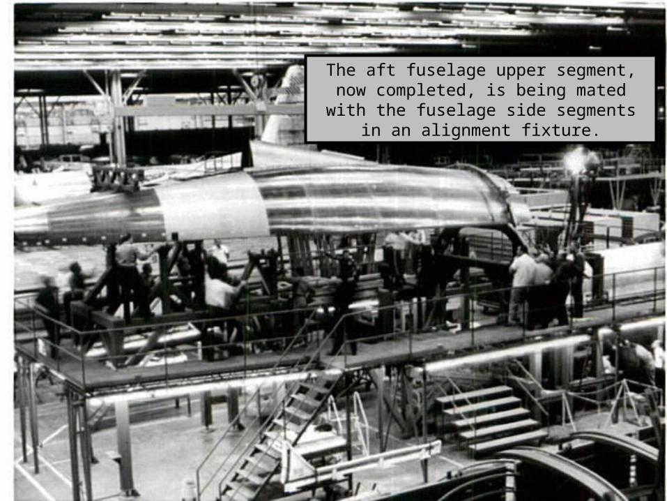
The aft fuselage upper segment, now completed, is being mated with the fuselage
side segments in an alignment fixture.
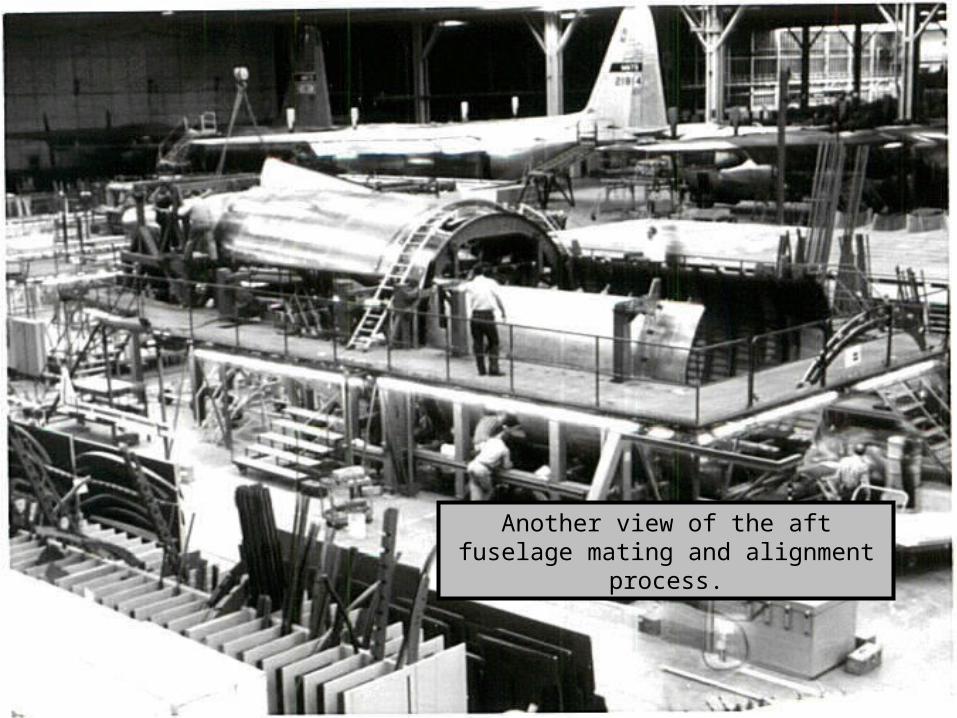
Another view of the aft fuselage mating and alignment process.
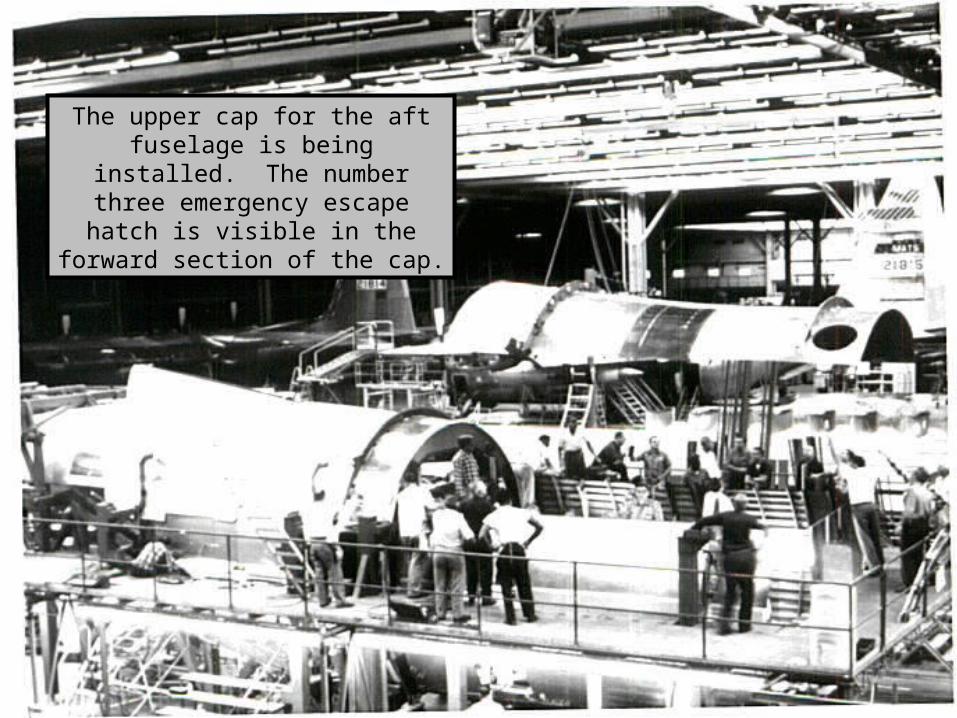
The upper cap for the aft fuselage is being installed. The number three emergency escape hatch is visible in the forward section of the cap.
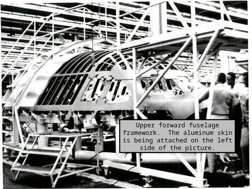
Upper forward fuselage framework. The aluminum skin is being attached
on the left side of the picture.
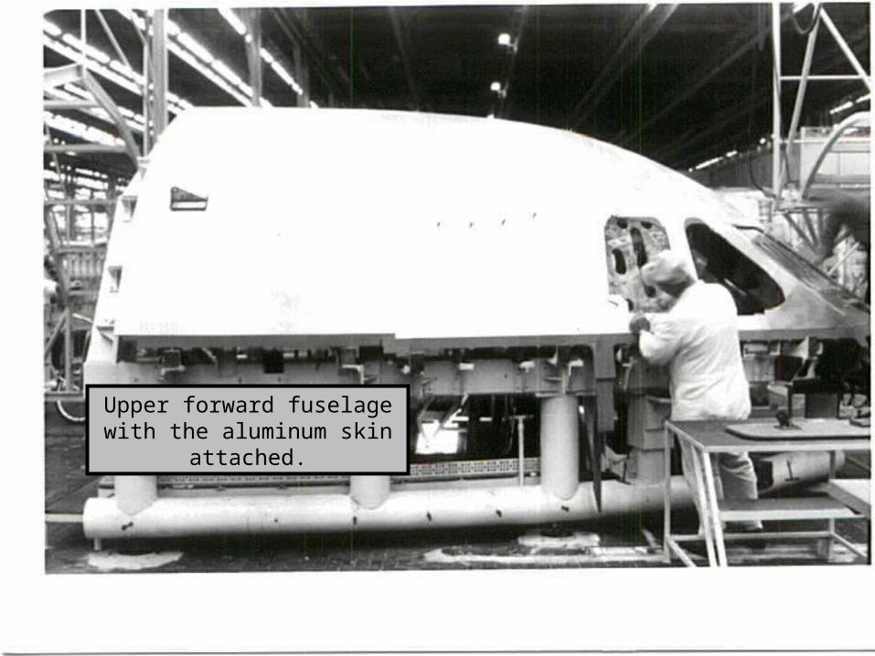
Upper forward fuselage with the aluminum skin attached.
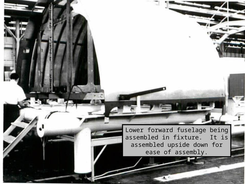
Lower forward fuselage being assembled in fixture. It is assembled upside down for ease of assembly.
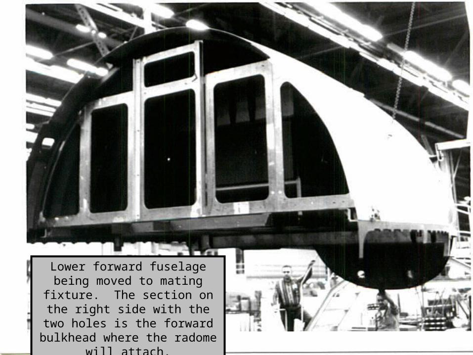
Lower forward fuselage being moved to mating fixture. The
section on the right side with the two holes is the forward bulkhead
where the radome will attach.
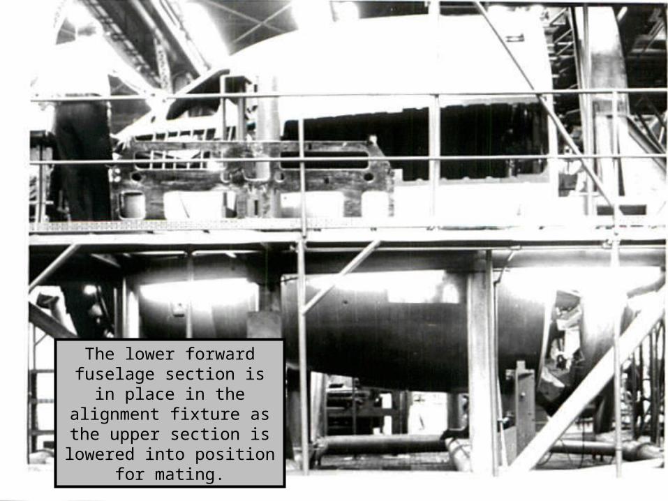
The lower forward fuselage section is in place in the alignment fixture as the
upper section is lowered into position for mating.
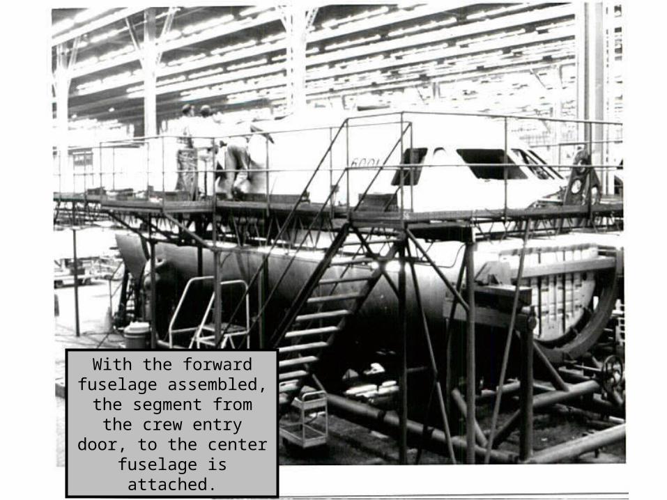
With the forward fuselage assembled, the segment from the crew entry door, to the center fuselage is
attached.
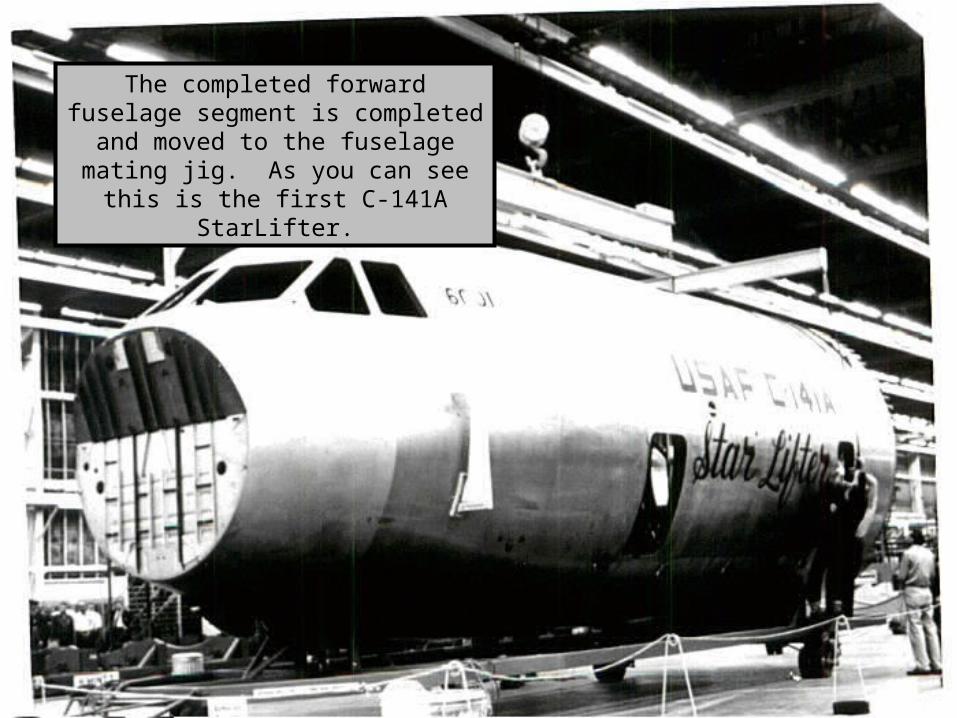
The completed forward fuselage segment is completed and moved to the fuselage mating jig. As you can see this is the first C-141A StarLifter.
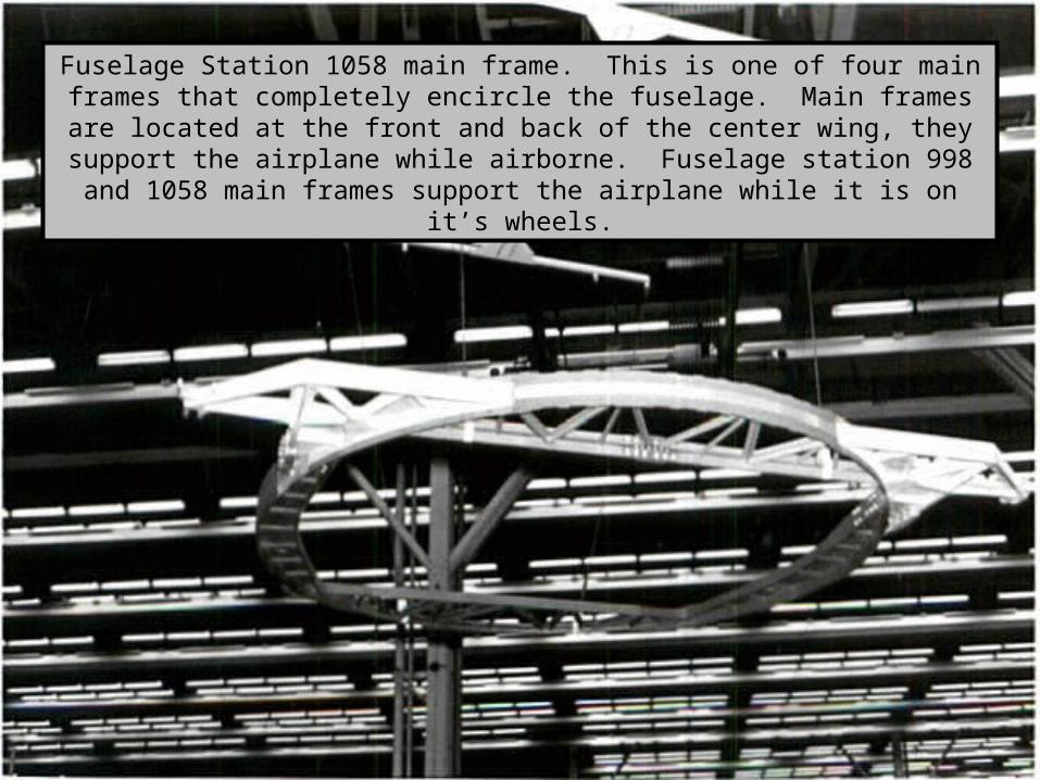
Fuselage Station 1058 main frame. This is one of four main frames that completely encircle the fuselage. Main frames are located at the front and back of the center wing, they support the airplane while airborne. Fuselage station
998 and 1058 main frames support the airplane while it is on it’s wheels.
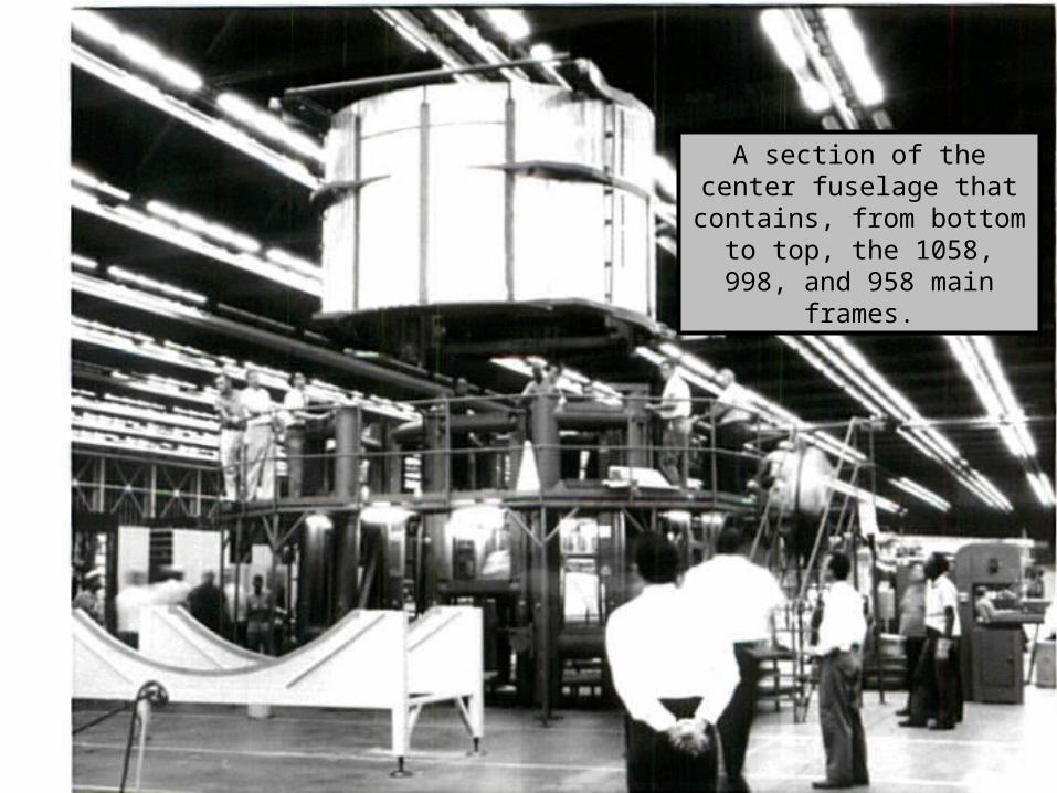
A section of the center fuselage that contains, from bottom to top, the 1058, 998,
and 958 main frames.
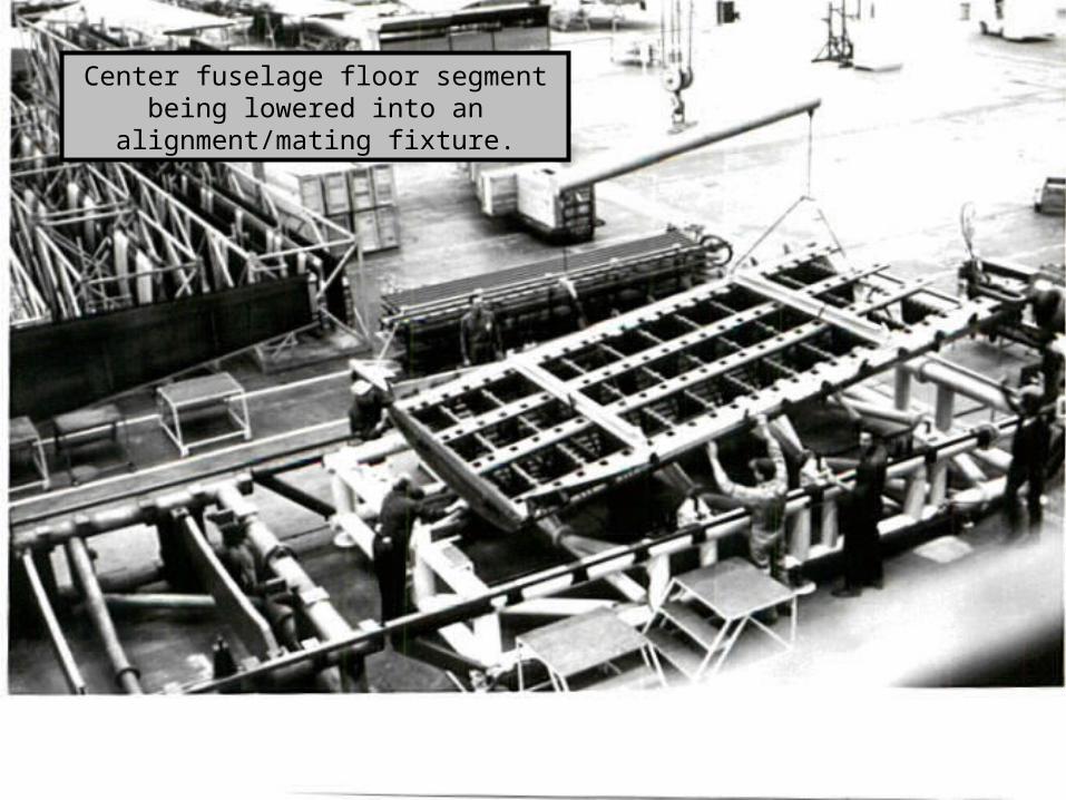
Center fuselage floor segment being lowered into an alignment/mating fixture.
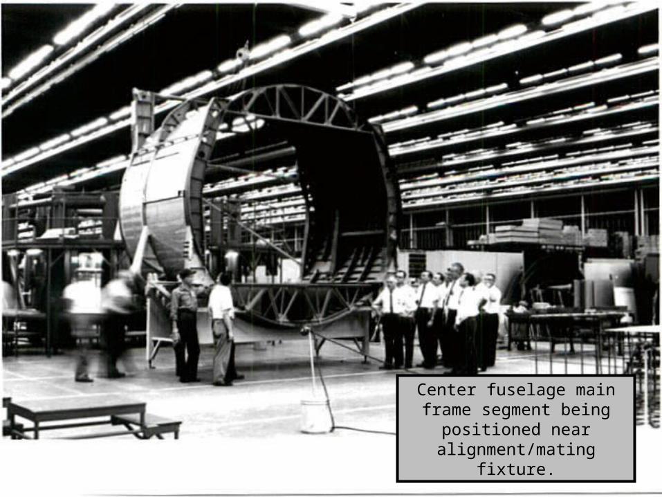
Center fuselage main frame segment being positioned
near alignment/mating fixture.
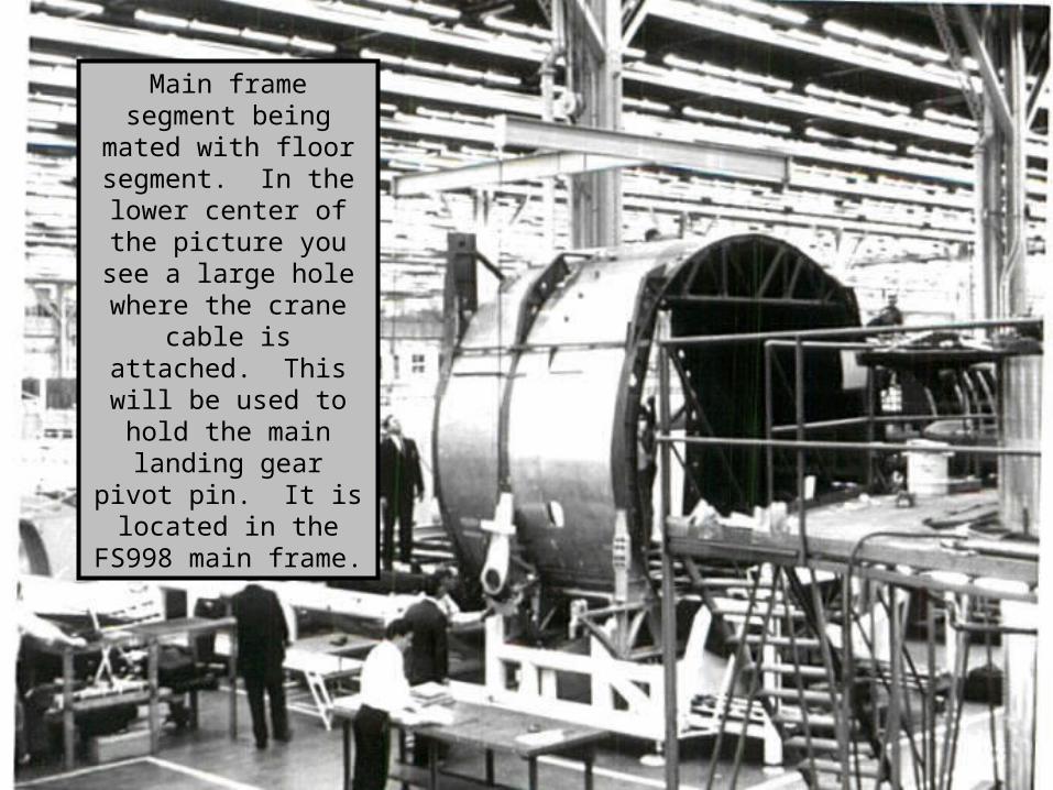
Main frame segment being mated with floor segment. In the lower center of the picture you see a large hole
where the crane cable is attached. This will be used to hold the
main landing gear pivot pin. It is located in the
FS998 main frame.
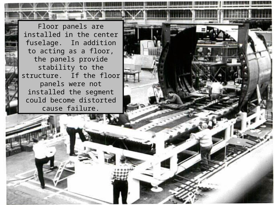
Floor panels are installed in the center fuselage. In addition to
acting as a floor, the panels provide stability to the structure.
If the floor panels were not installed the segment could
become distorted cause failure.
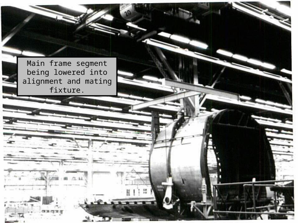
Main frame segment being lowered into alignment and
mating fixture.
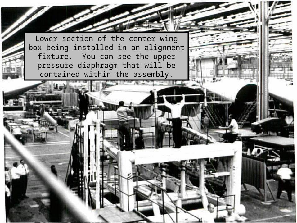
Lower section of the center wing box being installed in an alignment fixture. You can see
the upper pressure diaphragm that will be contained within the assembly.
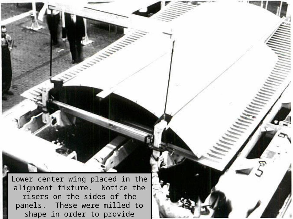
Lower center wing placed in the alignment fixture. Notice the risers on the sides of
the panels. These were milled to shape in order to provide strength to the panels.
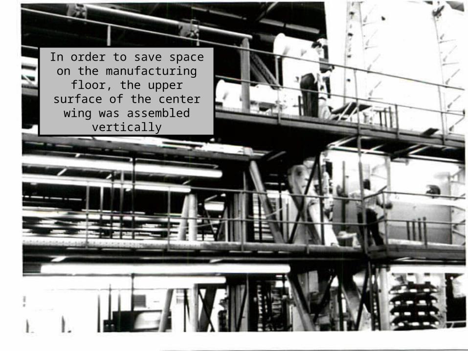
In order to save space on the manufacturing floor, the upper surface of the center wing was
assembled vertically
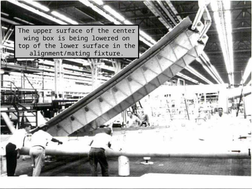
The upper surface of the center wing box is being lowered on top of the lower
surface in the alignment/mating fixture.
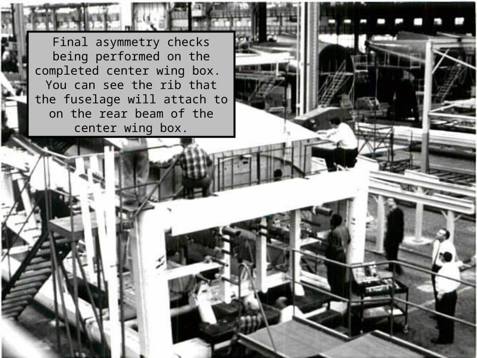
Final asymmetry checks being performed on the completed center wing box. You can see the rib that
the fuselage will attach to on the rear beam of the center wing box.
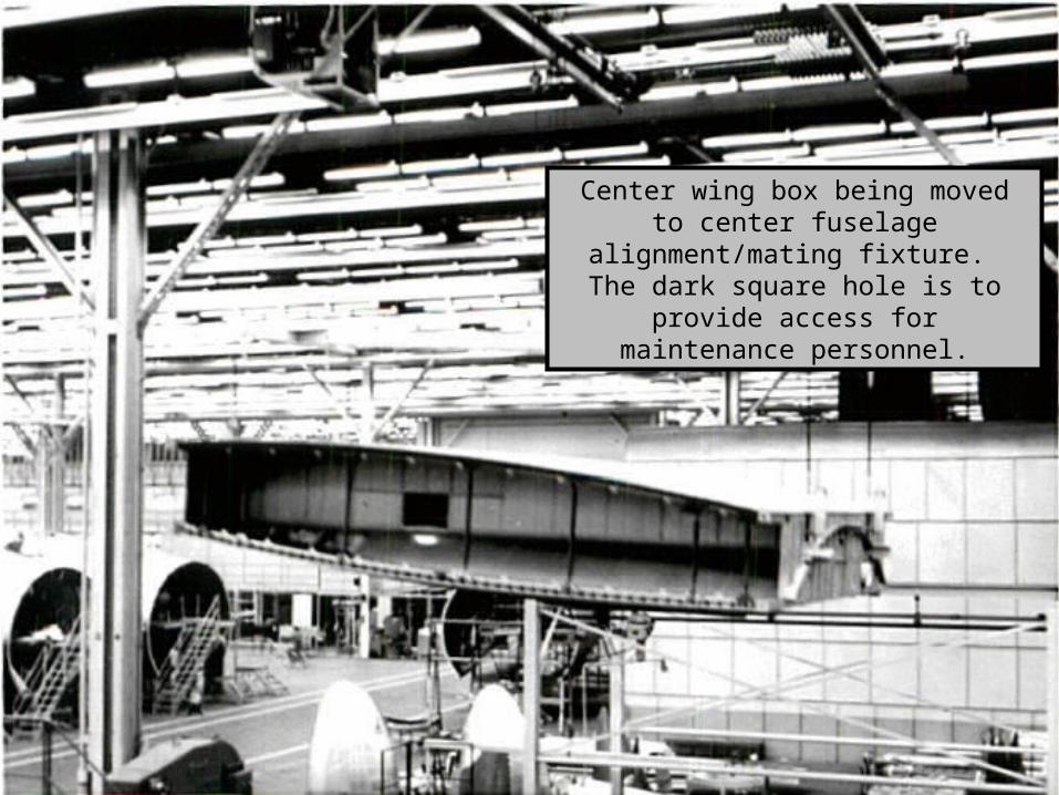
Center wing box being moved to center fuselage alignment/mating fixture. The dark square hole is to provide access
for maintenance personnel.
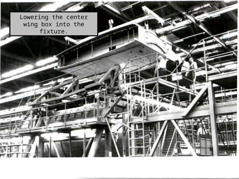
Lowering the center wing box into the fixture.
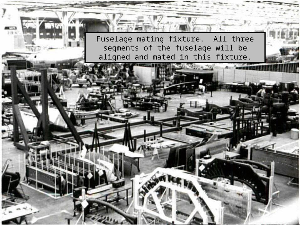
Fuselage mating fixture. All three segments of the fuselage will be aligned and mated in this fixture.
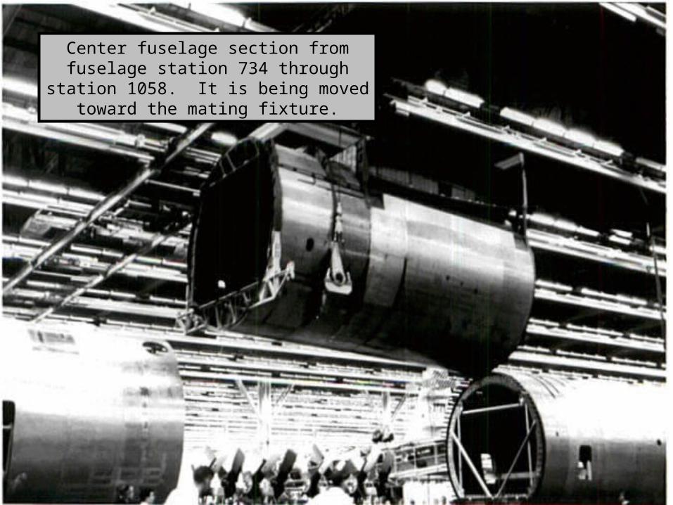
Center fuselage section from fuselage station 734 through station 1058. It is being moved toward the mating fixture.
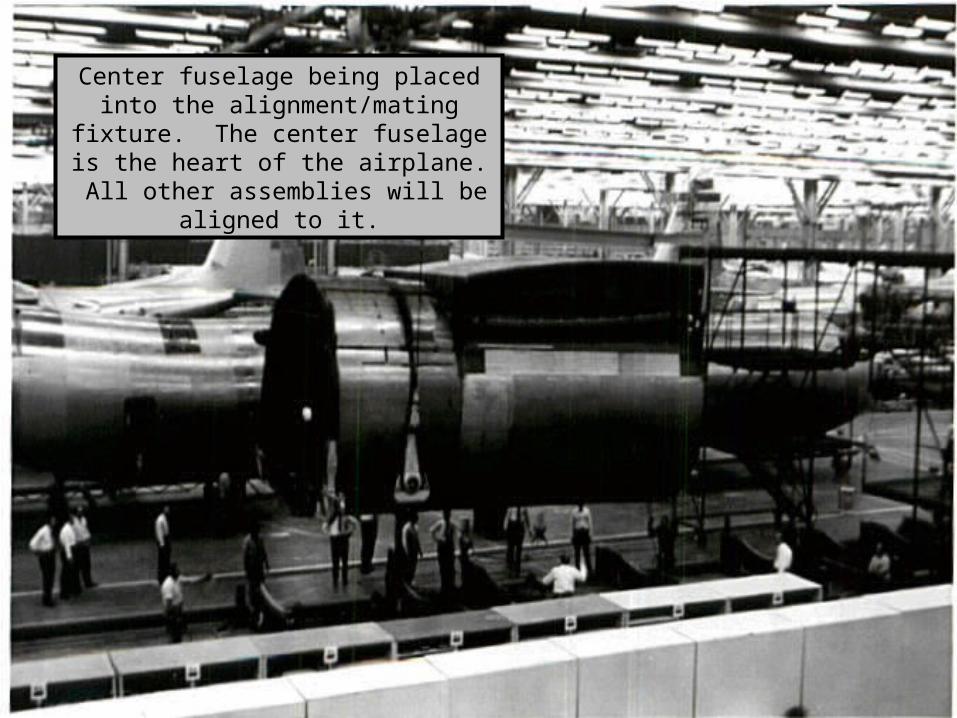
Center fuselage being placed into the alignment/mating fixture. The center
fuselage is the heart of the airplane. All other assemblies will be aligned to it.
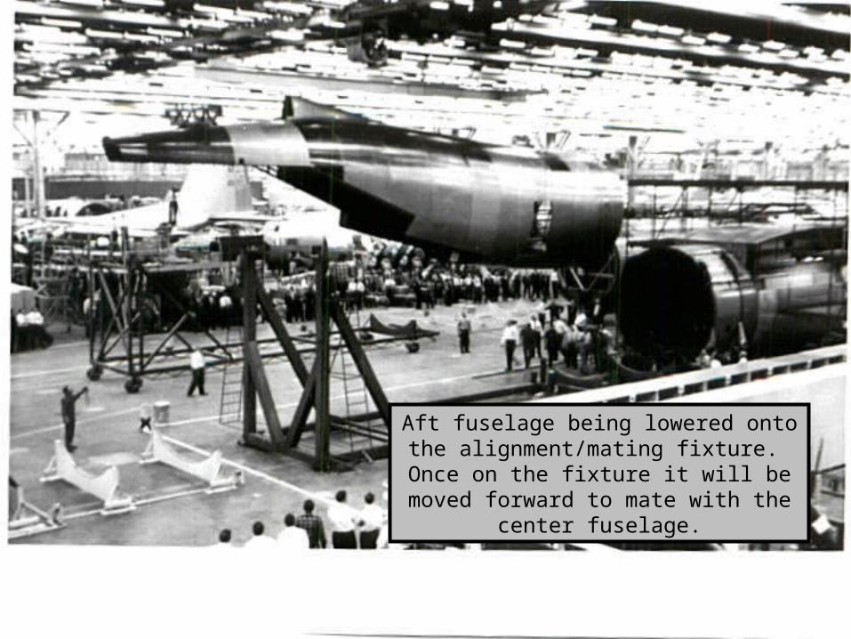
Aft fuselage being lowered onto the alignment/mating fixture. Once on the fixture it will be moved forward to mate
with the center fuselage.
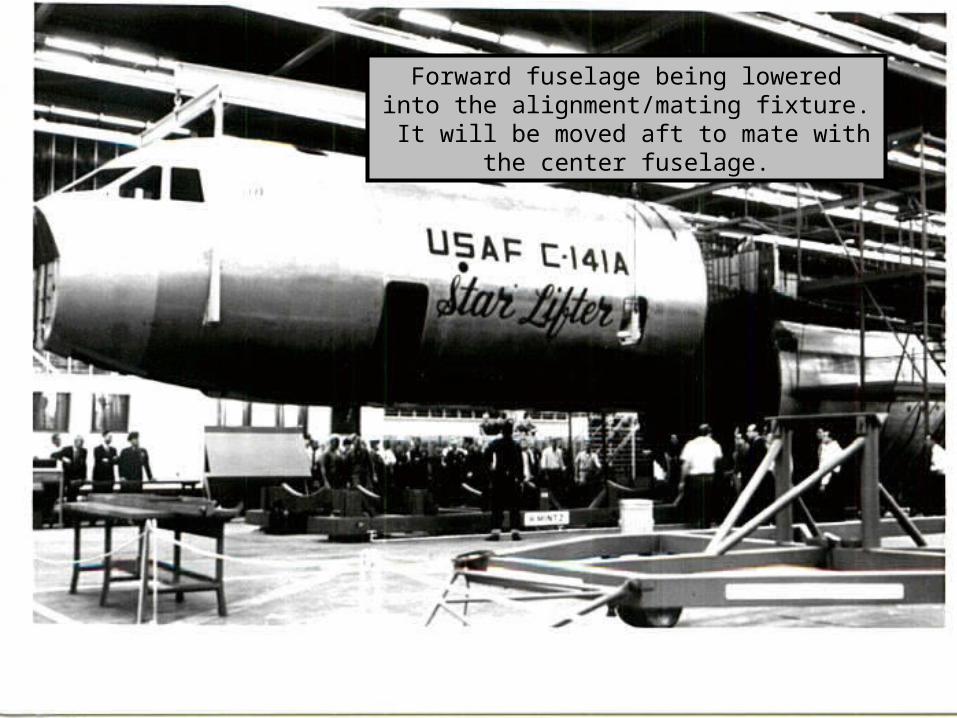
Forward fuselage being lowered into the alignment/mating fixture. It will be moved aft to
mate with the center fuselage.
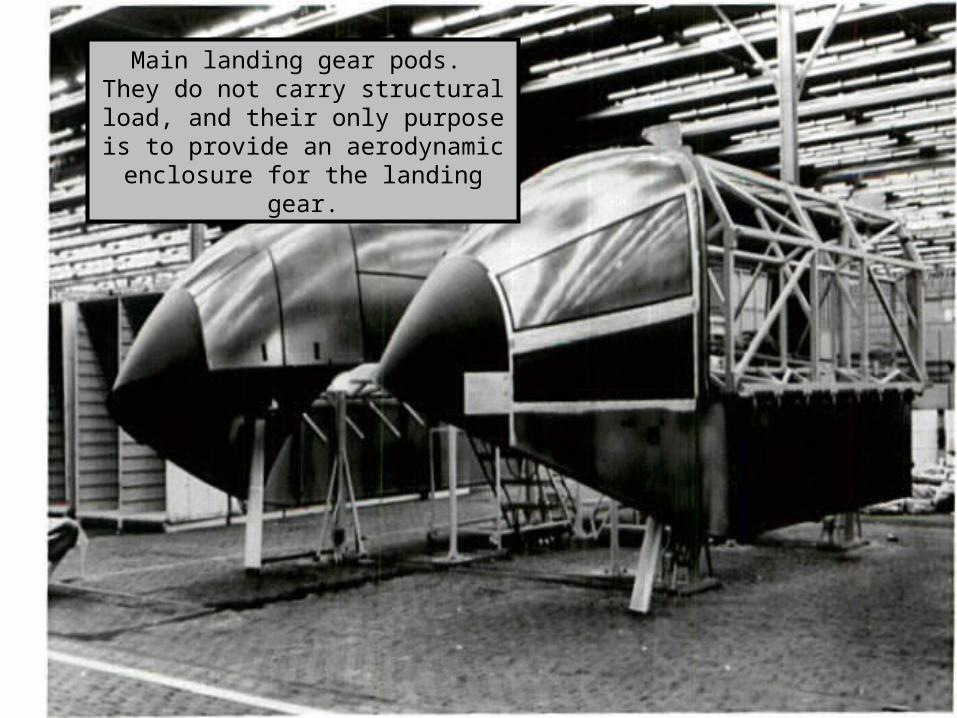
Main landing gear pods. They do not carry structural load, and their only
purpose is to provide an aerodynamic enclosure for the landing gear.
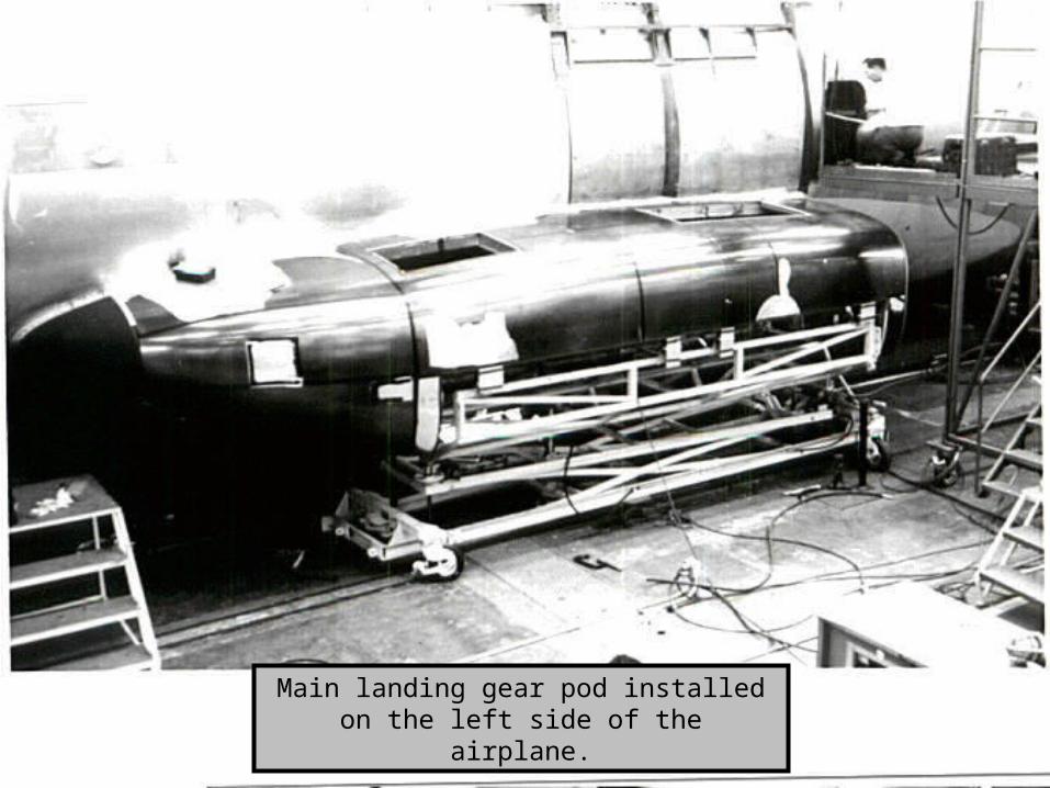
Main landing gear pod installed on the left side of the airplane.
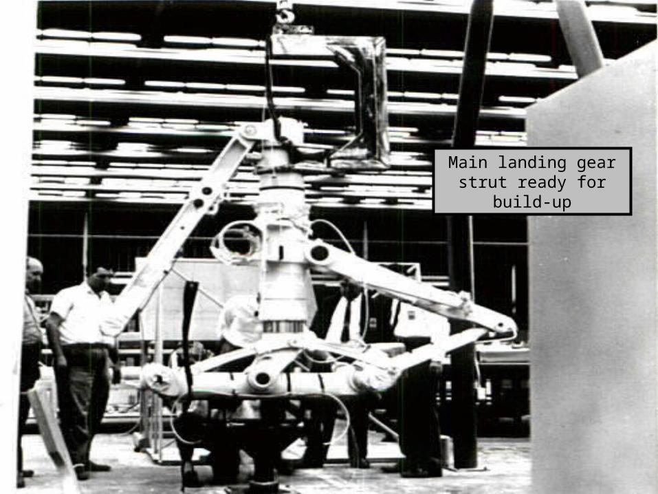
Main landing gear strut ready for build-up
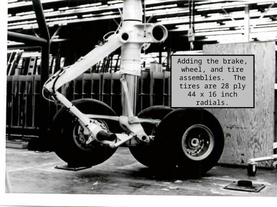
Adding the brake, wheel, and tire assemblies. The tires are 28 ply 44 x 16
inch radials.
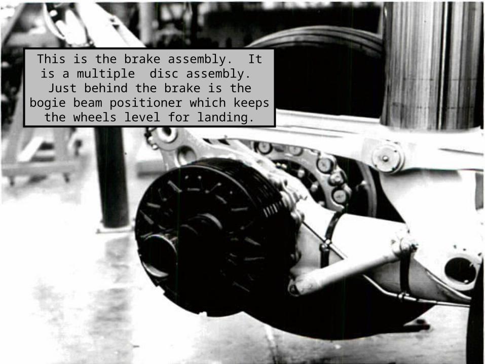
This is the brake assembly. It is a multiple disc assembly. Just behind the brake is the
bogie beam positioner which keeps the wheels level for landing.
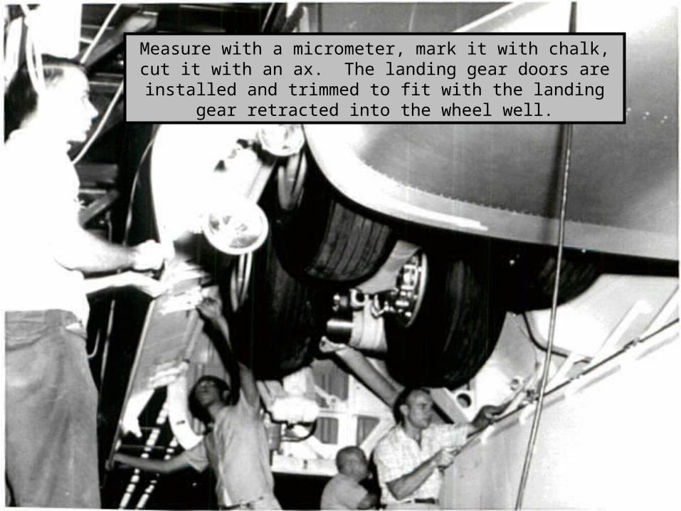
Measure with a micrometer, mark it with chalk, cut it with an ax. The landing gear doors are installed and trimmed to fit with the
landing gear retracted into the wheel well.
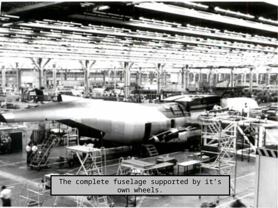
The complete fuselage supported by it’s own wheels.
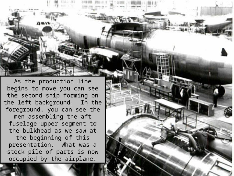
As the production line begins to move you can see the second ship forming
on the left background. In the foreground, you can see the men assembling the aft fuselage upper
segment to the bulkhead as we saw at the beginning of this presentation.
What was a stock pile of parts is now occupied by the airplane.
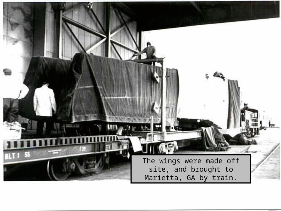
The wings were made off site, and brought to Marietta, GA by train.
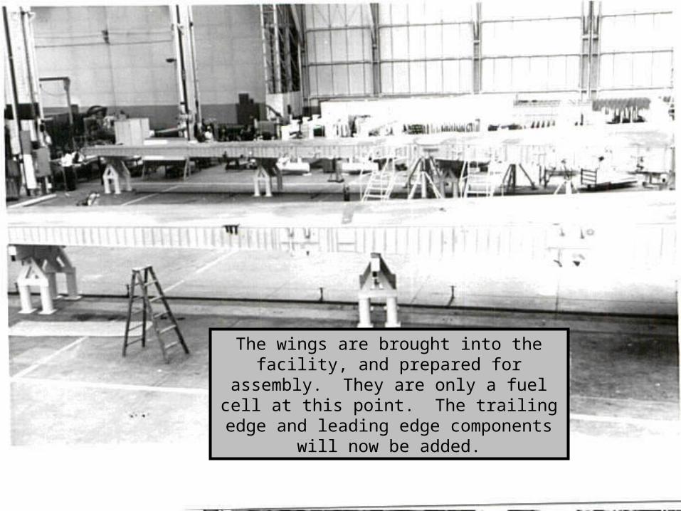
The wings are brought into the facility, and prepared for assembly. They are only a fuel
cell at this point. The trailing edge and leading edge components will now be added.
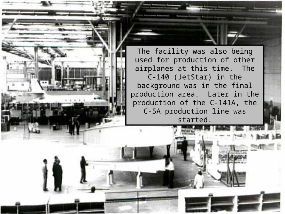
The facility was also being used for production of other airplanes at this time.
The C-140 (JetStar) in the background was in the final production area. Later in the production of the C-141A, the C-5A
production line was started.
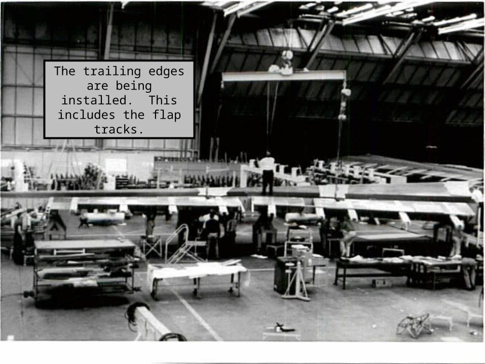
The trailing edges are being installed. This
includes the flap tracks.
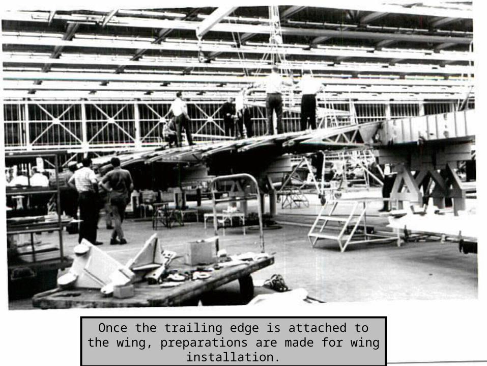
Once the trailing edge is attached to the wing, preparations are made for wing installation.

The wing is in transit. If you notice the crane operator is in the little bucket up near the ceiling. At that time, the crane operator rode up there, now he walks on
the floor with a long lead control box.
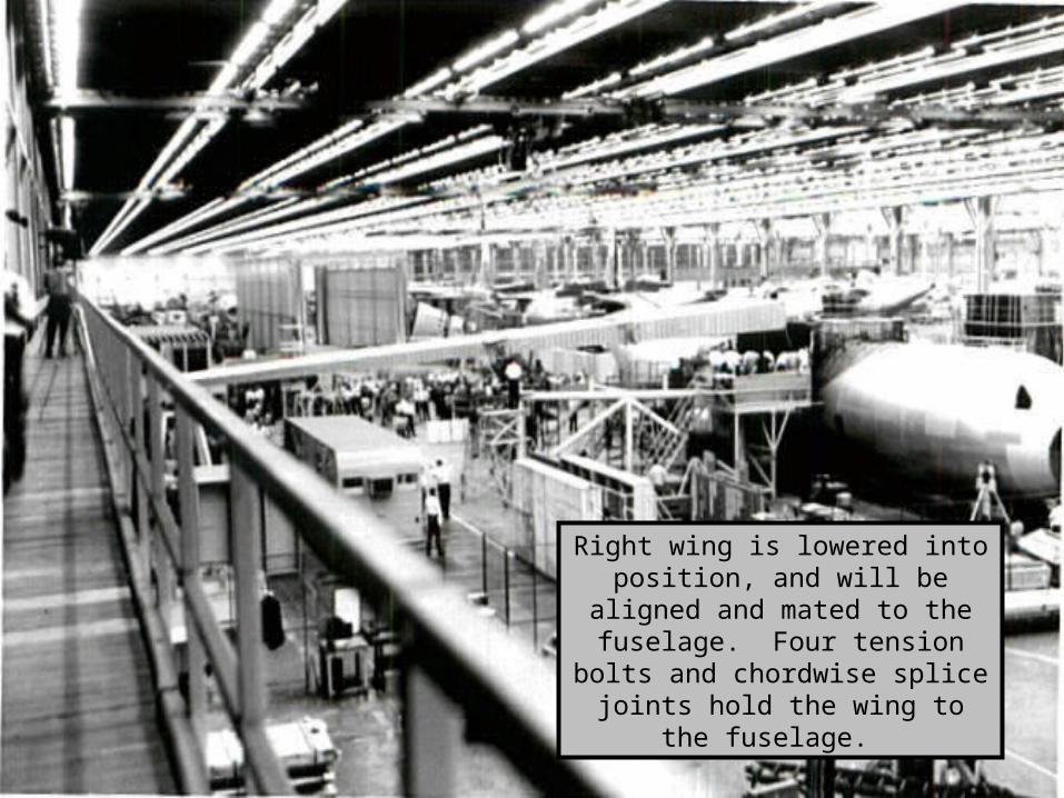
Right wing is lowered into position, and will be aligned and mated to the fuselage. Four tension bolts
and chordwise splice joints hold the wing to the fuselage.
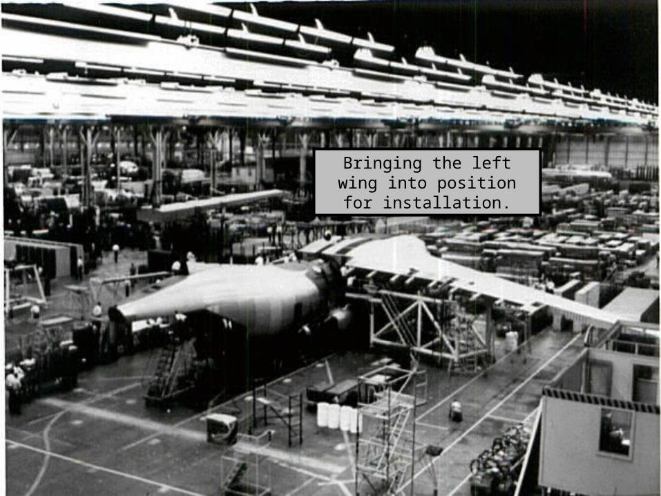
Bringing the left wing into position for installation.
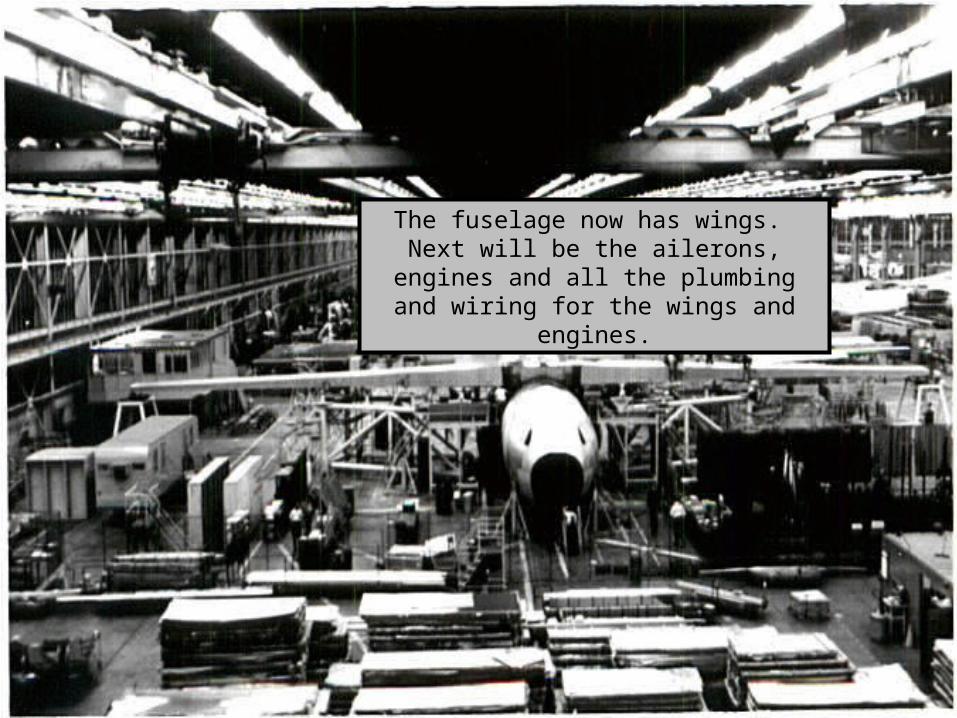
The fuselage now has wings. Next will be the ailerons, engines and all the plumbing
and wiring for the wings and engines.
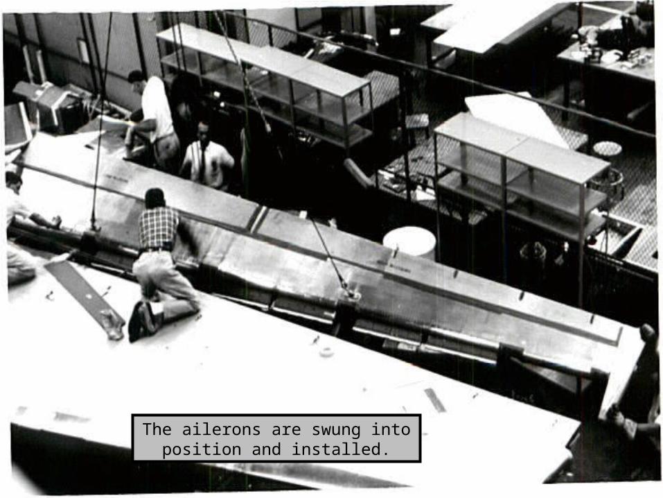
The ailerons are swung into position and installed.
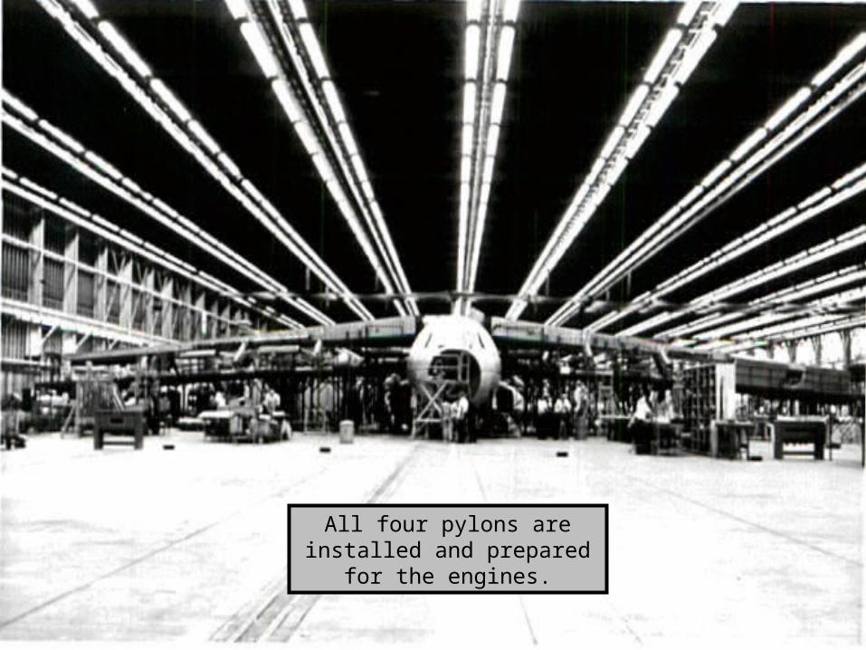
All four pylons are installed and prepared for the engines.
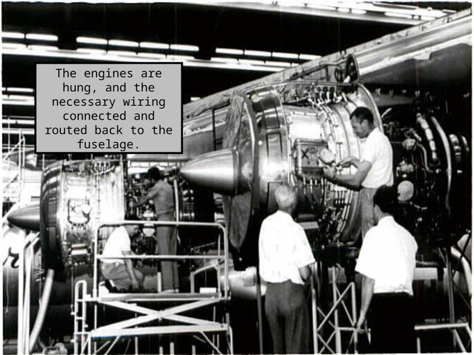
The engines are hung, and the necessary wiring
connected and routed back to the fuselage.
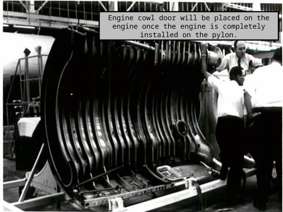
Engine cowl door will be placed on the engine once the engine is completely installed on the pylon.
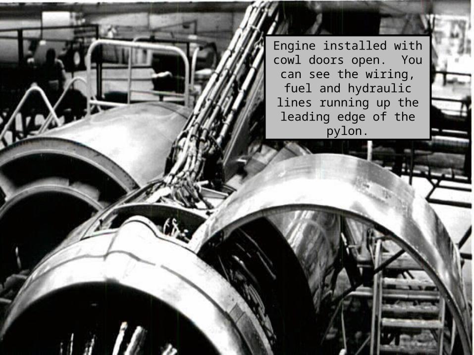
Engine installed with cowl doors open. You can see the
wiring, fuel and hydraulic lines running up the leading
edge of the pylon.
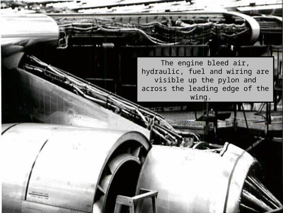
The engine bleed air, hydraulic, fuel and wiring are visible up the pylon and across
the leading edge of the wing.
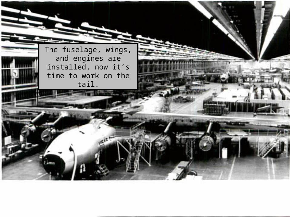
The fuselage, wings, and engines are installed, now it’s time to work on the tail.
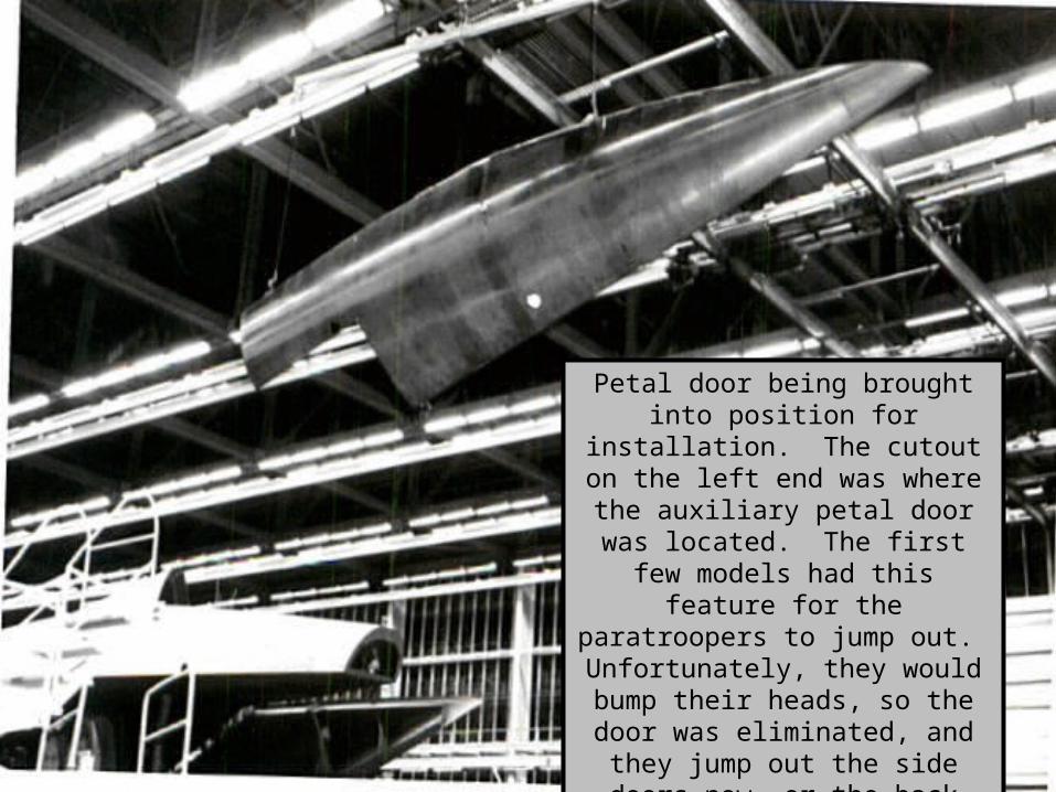
Petal door being brought into position for installation. The cutout
on the left end was where the auxiliary petal door was located.
The first few models had this feature for the paratroopers to jump
out. Unfortunately, they would bump their heads, so the door was eliminated, and they jump out the side doors now, or the back with
the petal doors open to the air drop position.
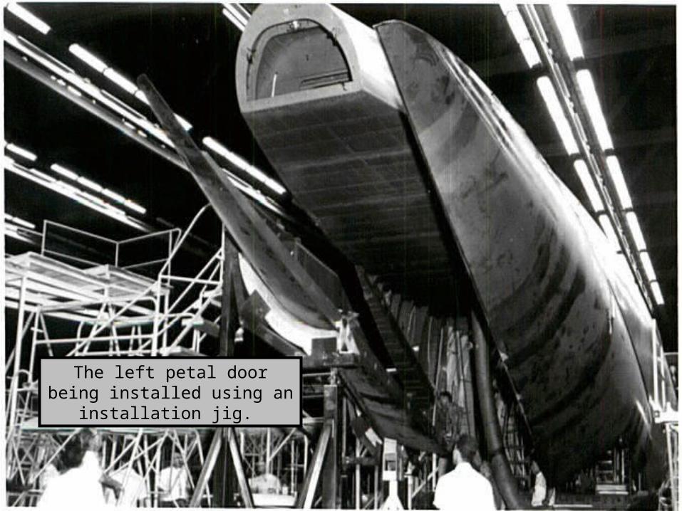
The left petal door being installed using an installation jig.
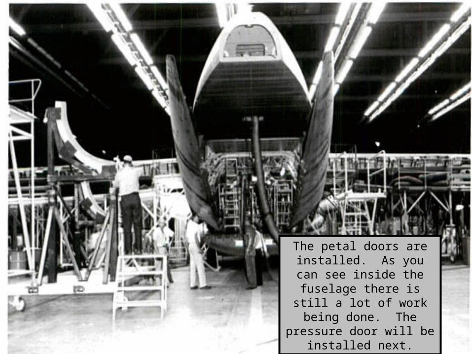
The petal doors are installed. As you can see inside the
fuselage there is still a lot of work being done. The pressure door will be
installed next.
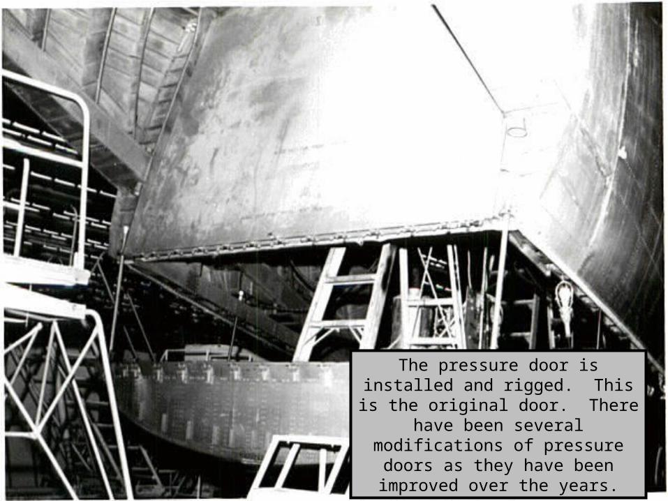
The pressure door is installed and rigged. This is the original door.
There have been several modifications of pressure doors as they have been improved over the
years.
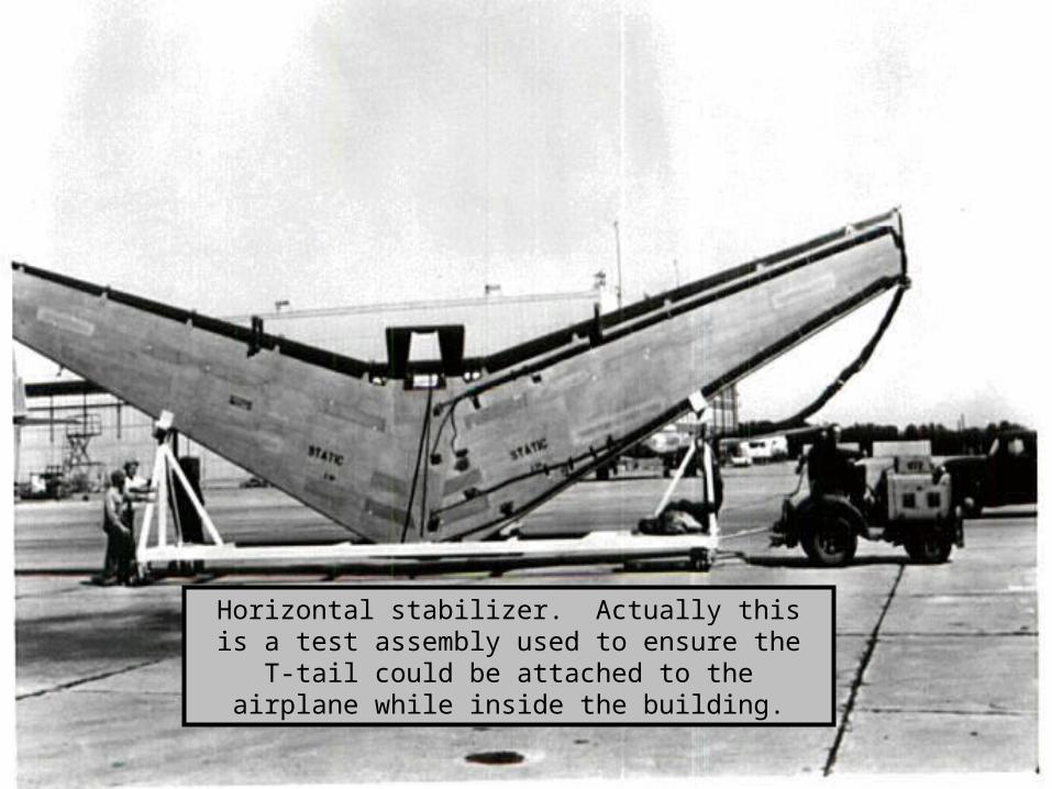
Horizontal stabilizer. Actually this is a test assembly used to ensure the T-tail could be attached to the
airplane while inside the building.
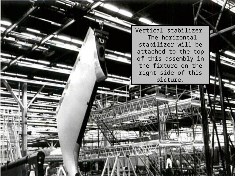
Vertical stabilizer. The horizontal stabilizer will be attached to the top of this assembly in the fixture on
the right side of this picture.
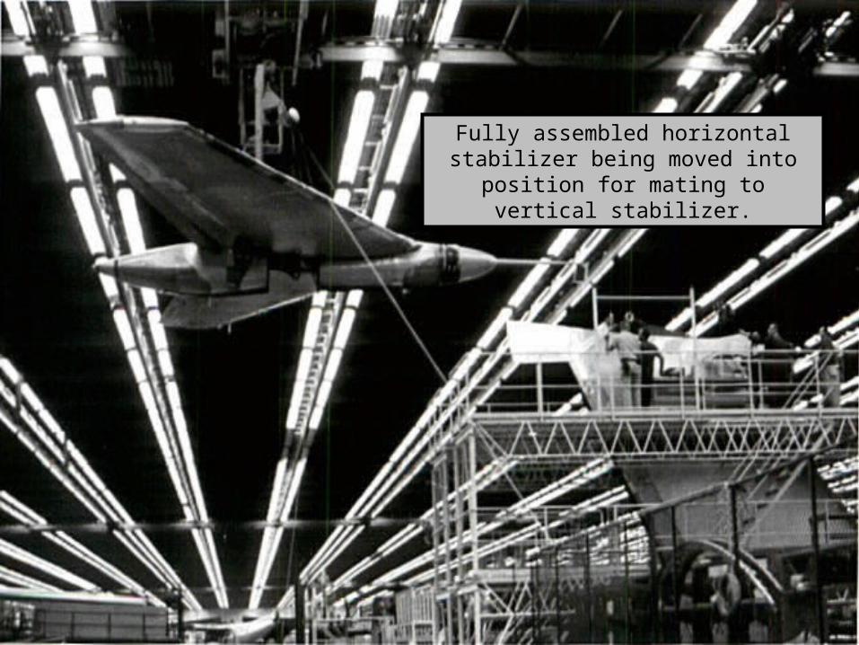
Fully assembled horizontal stabilizer being moved into position for mating to
vertical stabilizer.
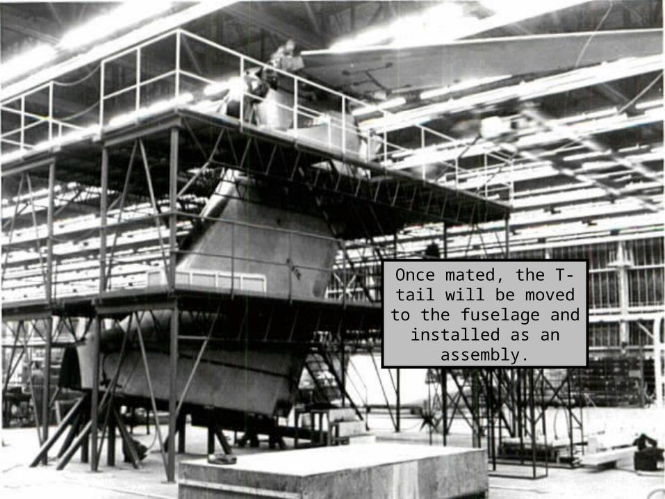
Once mated, the T-tail will be moved to the fuselage
and installed as an assembly.
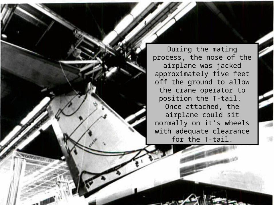
During the mating process, the nose of the airplane was jacked approximately five feet off the
ground to allow the crane operator to position the T-tail. Once
attached, the airplane could sit normally on it’s wheels with
adequate clearance for the T-tail.
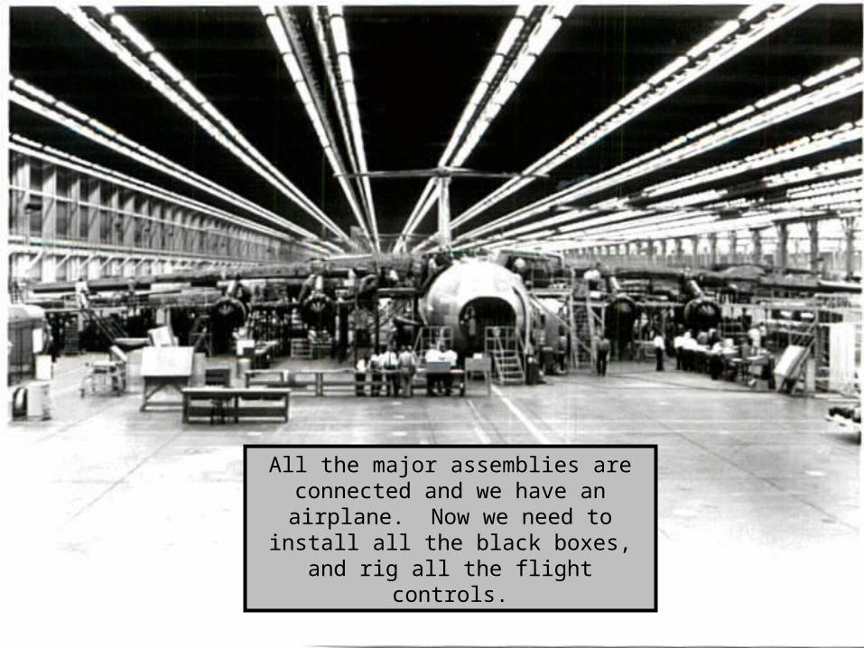
All the major assemblies are connected and we have an airplane. Now we need to install all the black boxes, and rig all
the flight controls.
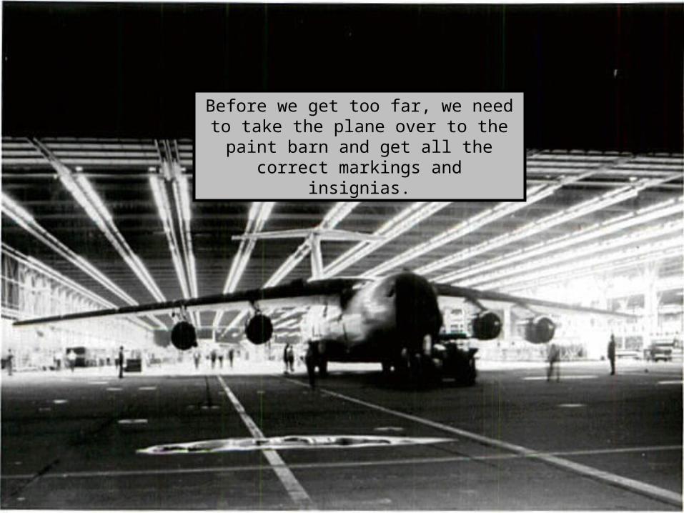
Before we get too far, we need to take the plane over to the paint barn and get all the correct markings and insignias.
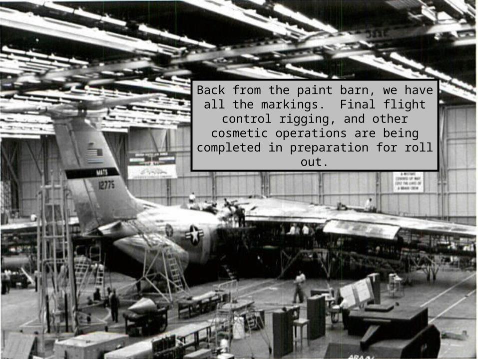
Back from the paint barn, we have all the markings. Final flight control rigging, and
other cosmetic operations are being completed in preparation for roll out.
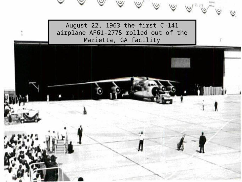
August 22, 1963 the first C-141 airplane AF61-2775 rolled out of the Marietta, GA facility
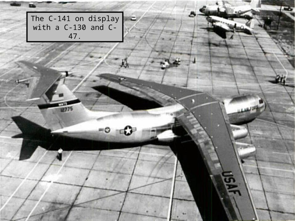
The C-141 on display with a C-130 and C-47.
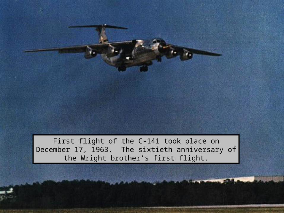
First flight of the C-141 took place on December 17, 1963. The sixtieth anniversary of the Wright brother’s first flight.
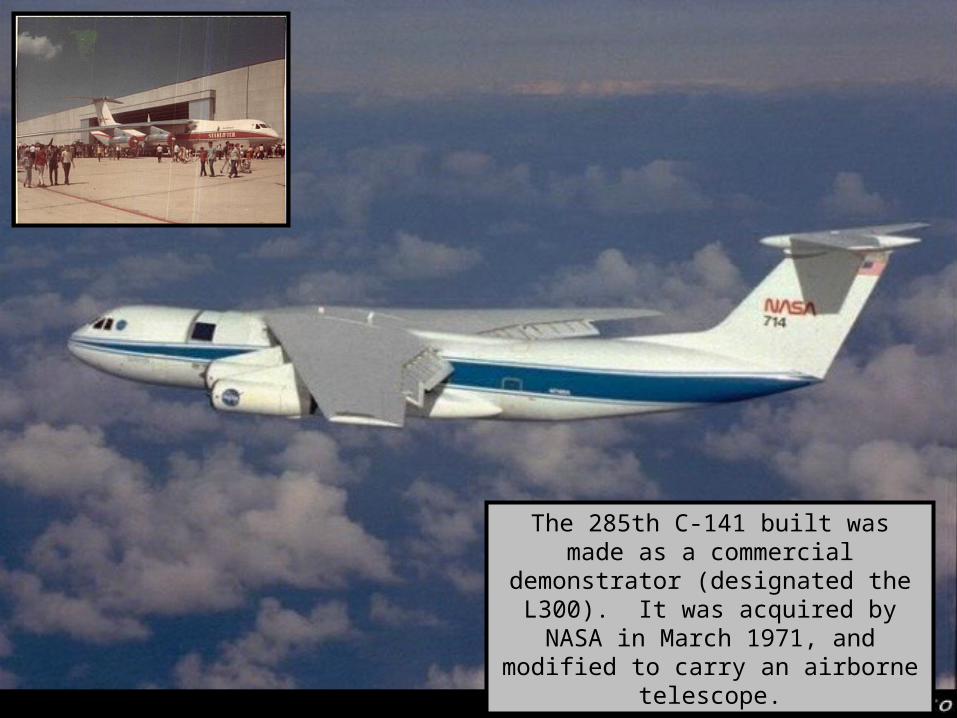
The 285th C-141 built was made as a commercial demonstrator (designated the L300). It was acquired by NASA in March 1971, and modified to carry an
airborne telescope.
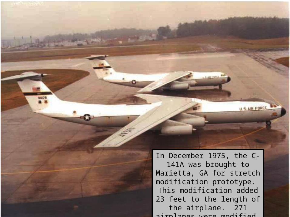
In December 1975, the C-141A was brought to Marietta, GA for stretch modification prototype. This modification added 23 feet
to the length of the airplane. 271 airplanes were modified.
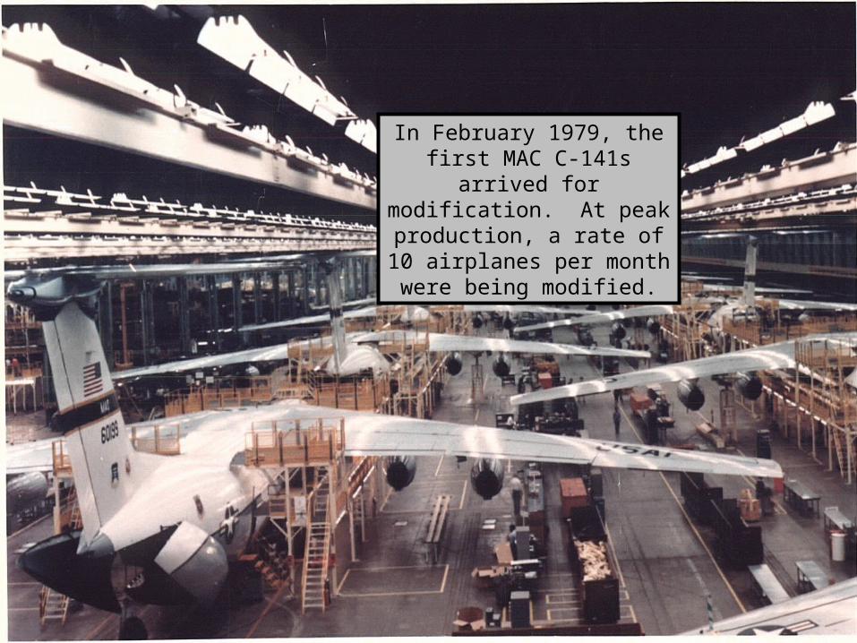
In February 1979, the first MAC C-141s arrived for modification. At peak
production, a rate of 10 airplanes per month were
being modified.
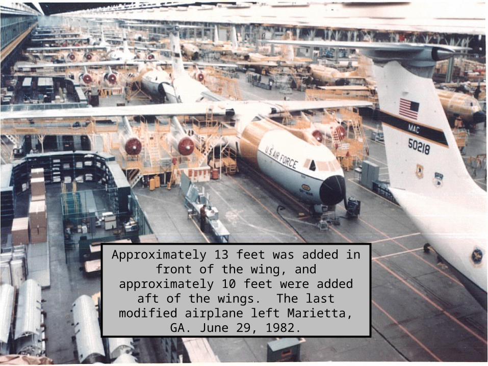
Approximately 13 feet was added in front of the wing, and approximately 10 feet were added aft
of the wings. The last modified airplane left Marietta, GA. June 29, 1982.
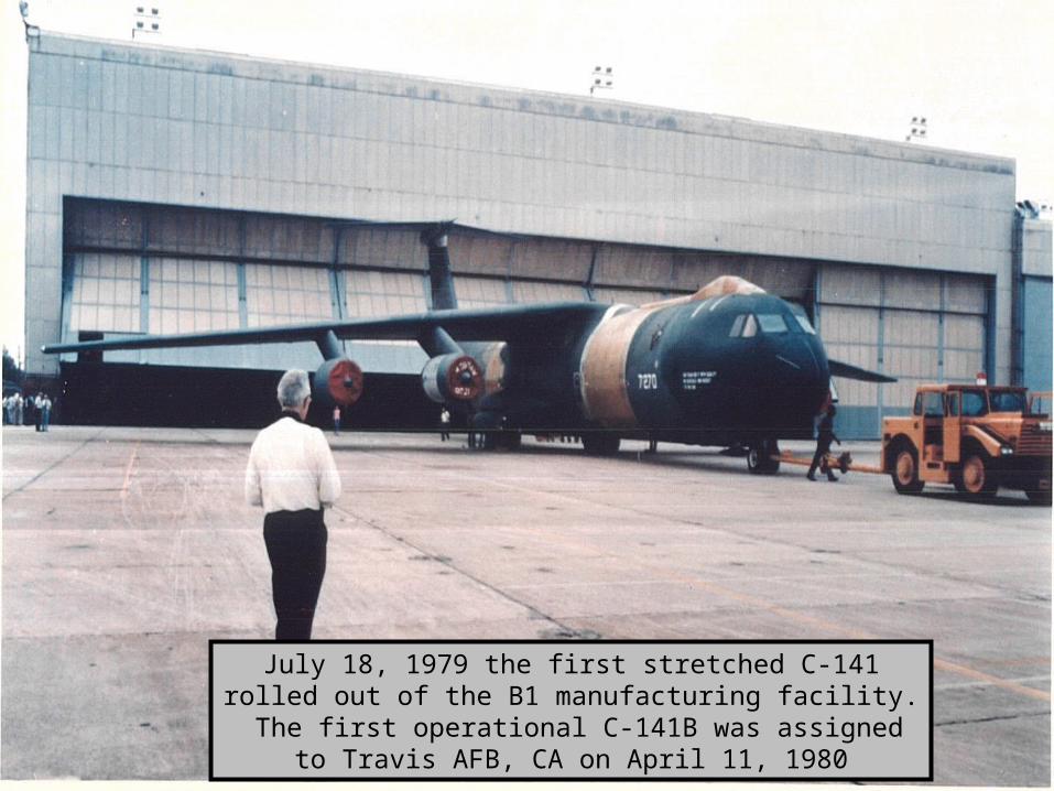
July 18, 1979 the first stretched C-141 rolled out of the B1 manufacturing facility. The first operational C-141B was
assigned to Travis AFB, CA on April 11, 1980
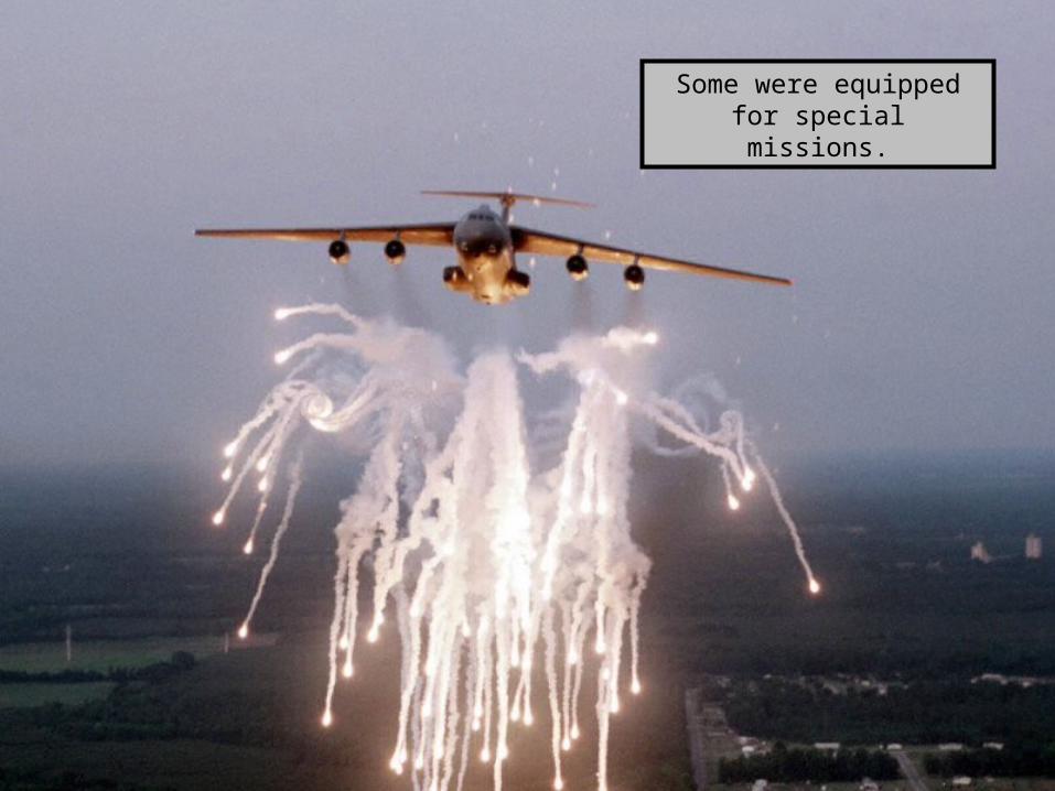
Some were equipped for special missions.
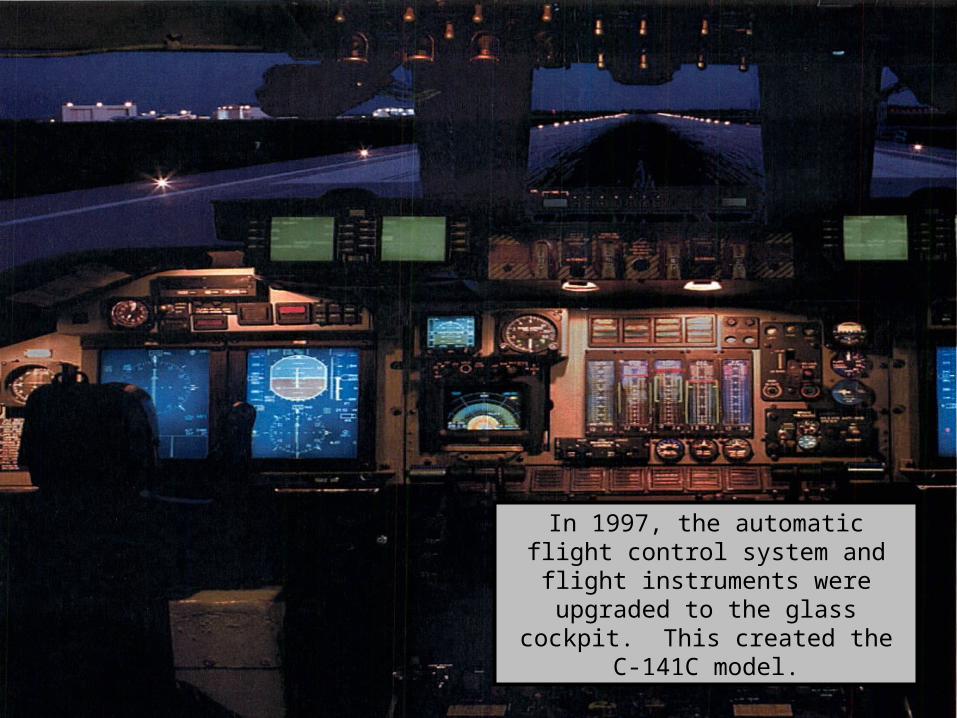
In 1997, the automatic flight control system and flight instruments were upgraded to the glass cockpit. This
created the C-141C model.

As off January 31, 2002, the C-141 has flown 10,508,631 hours, and has
more years to fly.
![[1] 1 2 5 6 15 a 15 a Q) ¥33, ¥33, 000. - 000. - 000. - 15 14 29 04 51 16 53 53 00 17 50 56 08 50 00 40 15 46 09 18 00 09 35 141 141 141 141 141 141 141 141 141 141 141 141 54 49](https://img.pdfslide.net/doc/110x75/5f09a6d27e708231d427dc4e/1-1-2-5-6-15-a-15-a-q-33-33-000-000-000-15-14-29-04-51-16-53-53.jpg)