Embed Size (px)
Citation preview
The Calculated Justification of Seismic Stability of Load-Lifting Cranes
NIKOLAI PANASENKO (1)
,
ALEKSEI SINELSHCHIKOV (2)
,
VADIM RABEY (3)
Lifting-and-Transport Machines, Industrial Logistics and Mechanics of Machines
Astrakhan State Technical University
414025, Russia, Astrakhan, St. Tatishcheva, 16
RUSSIA (1)
[email protected]; (2)
[email protected]; (3)
Abstract: - To provide seismic safety for engineering structures remains a prevalent problem. In particular,
attention is given to facilities whose destruction can cause damage to the population and the environment, such
as the facilities that use nuclear energy. According to the maps of the general seismic regionalization OSR-97,
independent spent fuel storage installation (ISFSI) with crane loadings of mining and chemical plant (MCP)
(Zheleznogorsk, Krasnoyarsk Territory, Russian Federation) was related to 7 magnitude zones according to the
MSK-64 scale. To justify the seismic safety using FEA, a dynamic spatial model of the MCP’s building was
developed, which includes bridge cranes with lifting capacities of 160/32 t, 16/3.2 t and 15 t. The model was
used for the floor accelerogram plotting at elevation marks of the cranes’ installment at +23 m, +16.8 m and
+8.55 m and for the strength calculation of the supporting systems of the building using the dynamic analysis
method (DAM) and the linear-spectral method (LSM). The equations of motion with multiple degrees of
freedom of the dynamic model were solved using the numerical Gear method and the linear-spectral method
(LSM). Based on the calculated floor accelerograms, the probability model of the seismic action was built in
the form of probability-statistical floor accelerograms for the elevation marks of the cranes’ installment. The
stress-strain state of the building and the bridge cranes was calculated under the seismic action conditions. The
development of the LSM theory was proposed for the spatial constructions of industrial buildings with crane
loadings. The efficiency of the proposed calculated methodology was established, and this proposed
methodology was tested in the industrial sphere of a facility with nuclear energy usage that conforms to
tightened seismic safety standards.
Key-Words: - Seismic safety, Industrial buildings, Load-lifting cranes, Earthquake accelerograms, Equations of
motion, Stress-strain state
1 Introduction The mining and chemical plant (MCP)
(Zheleznogorsk, Krasnoyarsk Territory, Russian
Federation) is a nuclear energy facility (FUNE),
whose aseismic design, construction and use of
buildings, structures and technological and crane
equipment are regulated by the SNiP II-7-81*
"Construction in earthquake-prone regions" [1]
building code and normative documents [2,3]. In
these normative documents, updated maps of the
general seismic regionalization are included from
the OSR-97 map set. All facilities of the MCP were
erected prior to the publication of the OSR-97 maps
(Fig. 1), and until 1998, they were considered
seismically safe by the Russian Academy of
Sciences (RAS) [4]. According to the valid OSR-68
and OSR-78 at that time of the general seismic
regionalization of USSR territory, no seismic
stability was required for the facilities of the MCP
because the plant facilities that appeared in the
OSR-78 map were situated in the 5.0 magnitude
zone.
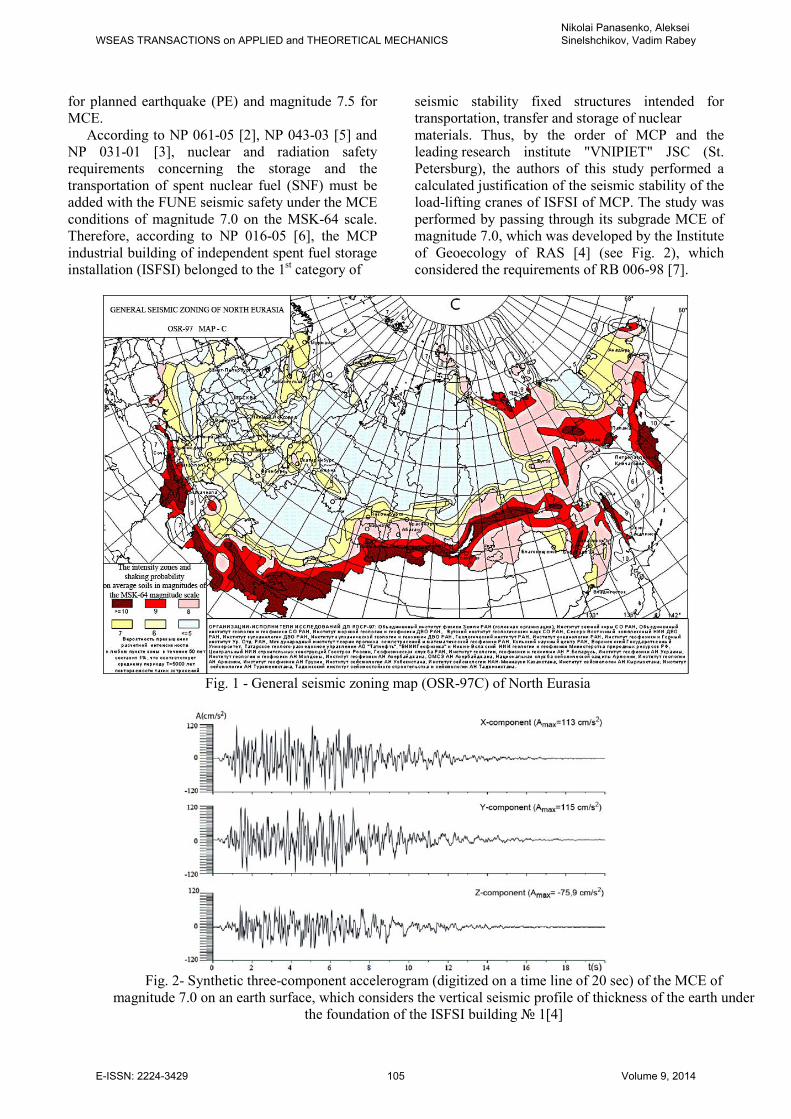
According to NP 031-01 [3], which has been
developed according to federal standards and rules
in the sphere of nuclear energy usage, the general
seismic regionalization maps in the territory of the
Russian Federation (OSR-97) and the
recommendations of International Atomic Energy
Agency (IAEA) ( 50-SG-D15, Vienna, 1992 and
50-SG-S1, Vienna, 1994), the seismic danger
around the MCP is determined from the OSR-97D
map for maximum credible earthquake (MCE) (see
Fig. 1). The OSR-97D map meets 99.5% probability
of not exceeding (or 0.5% possible exceeding) in the
course of 50 years of the predicted seismic intensity
of shaking in magnitude. According to SNiP II-7-
81*[1], for the average soil conditions of the 2nd
category, this result corresponds to magnitude 6.1
WSEAS TRANSACTIONS on APPLIED and THEORETICAL MECHANICSNikolai Panasenko, Aleksei Sinelshchikov, Vadim Rabey
E-ISSN: 2224-3429 104 Volume 9, 2014
for planned earthquake (PE) and magnitude 7.5 for
MCE.
According to NP 061-05 [2], NP 043-03 [5] and
NP 031-01 [3], nuclear and radiation safety
requirements concerning the storage and the
transportation of spent nuclear fuel (SNF) must be
added with the FUNE seismic safety under the MCE
conditions of magnitude 7.0 on the MSK-64 scale.
Therefore, according to NP 016-05 [6], the MCP
industrial building of independent spent fuel storage
installation (ISFSI) belonged to the 1st category of
seismic stability fixed structures intended for
transportation, transfer and storage of nuclear
materials. Thus, by the order of MCP and the
leading research institute "VNIPIET" JSC (St.
Petersburg), the authors of this study performed a
calculated justification of the seismic stability of the
load-lifting cranes of ISFSI of MCP. The study was
performed by passing through its subgrade MCE of
magnitude 7.0, which was developed by the Institute
of Geoecology of RAS [4] (see Fig. 2), which
considered the requirements of RB 006-98 [7].
Fig. 1 - General seismic zoning map (OSR-97C) of North Eurasia
Fig. 2- Synthetic three-component accelerogram (digitized on a time line of 20 sec) of the MCE of
magnitude 7.0 on an earth surface, which considers the vertical seismic profile of thickness of the earth under
the foundation of the ISFSI building 1[4]
WSEAS TRANSACTIONS on APPLIED and THEORETICAL MECHANICSNikolai Panasenko, Aleksei Sinelshchikov, Vadim Rabey
E-ISSN: 2224-3429 105 Volume 9, 2014
2 Problem Definition The following tasks had to be solved for the
calculation analysis of the seismic safety of ISFSI:
1) conformable elaboration of the principal
provisions of seismic stability theory to combine the
action of the supporting structures of the storage
building with a system of transportation and storage
of containers (100-120 ton) with SNF in the wet
storing pool [8, 9]; 2) development of a dynamic
model of the combined system of the ISFSI
industrial building considering the bridge cranes; 3)
development of a mathematical model of the ISFSI
seismic vibrations as a differential equation-of-
motion system with many degrees of freedom (in
this case, n=46207) based on the nonlinear theory of
finite element method (FEM) and solving it using
the dynamic analysis method (DAM) by
numerically integrating the seismic equation-of-
motion system; 4) development of a probability
model for the floor seismic load (SL) on the lifting
equipment in accordance with the elevation mark of
its installment on the runway rails; 5) development
of a dynamic model of four types of load-lifting
bridge cranes in service using different types of
loose gears (LG); 6) calculation analysis of the
seismic stability of the load-lifting bridge cranes in
the process of SNF transfer under the operation of
the SL DAM probability model by numerically
integrating the seismic equation-of-motion system
with many degrees of freedom.
3 Mathematical Model of Floor
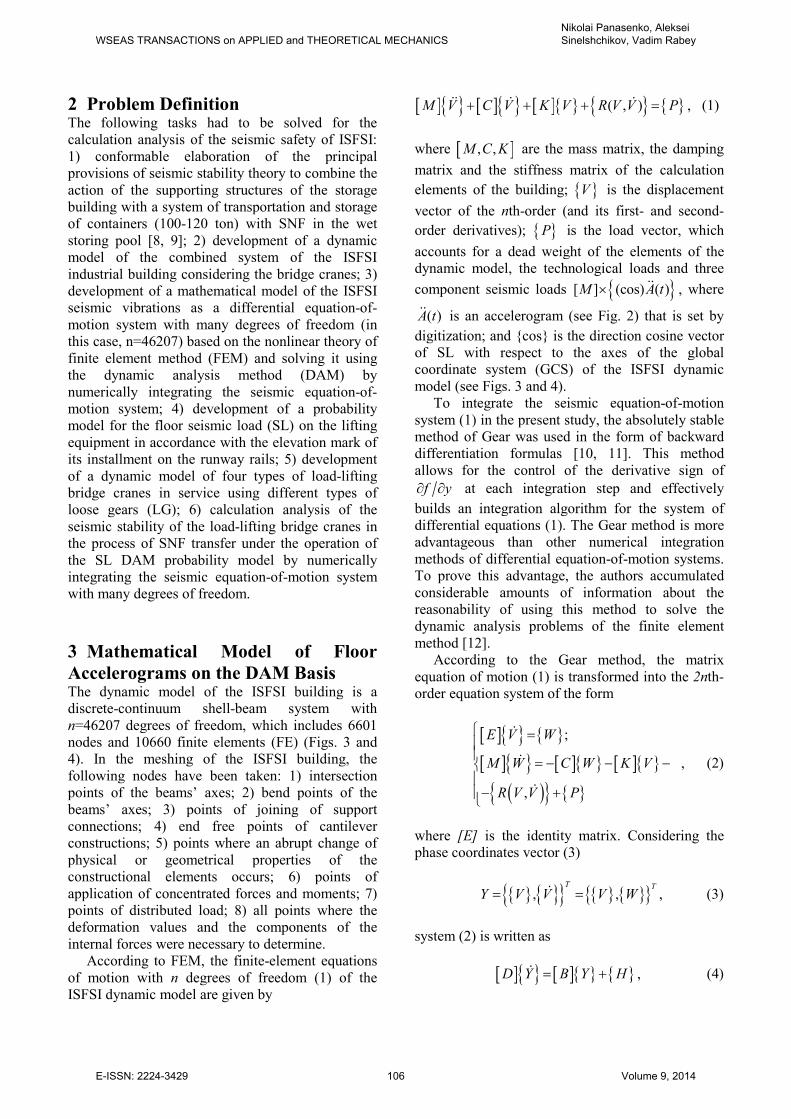
Accelerograms on the DAM Basis The dynamic model of the ISFSI building is a
discrete-continuum shell-beam system with
n=46207 degrees of freedom, which includes 6601
nodes and 10660 finite elements (FE) (Figs. 3 and
4). In the meshing of the ISFSI building, the
following nodes have been taken: 1) intersection
points of the beams’ axes; 2) bend points of the
beams’ axes; 3) points of joining of support
connections; 4) end free points of cantilever
constructions; 5) points where an abrupt change of
physical or geometrical properties of the
constructional elements occurs; 6) points of
application of concentrated forces and moments; 7)
points of distributed load; 8) all points where the
deformation values and the components of the
internal forces were necessary to determine. According to FEM, the finite-element equations
of motion with n degrees of freedom (1) of the
ISFSI dynamic model are given by
[ ] [ ] [ ] ( , )M V C V K V R V V P+ + + =ɺɺ ɺ ɺ , (1)
where [ ], ,M C K are the mass matrix, the damping
matrix and the stiffness matrix of the calculation
elements of the building; V is the displacement
vector of the nth-order (and its first- and second-
order derivatives); P is the load vector, which
accounts for a dead weight of the elements of the
dynamic model, the technological loads and three
component seismic loads [ ] (cos) ( )M A t× ɺɺ , where
( )A tɺɺ is an accelerogram (see Fig. 2) that is set by
digitization; and cos is the direction cosine vector
of SL with respect to the axes of the global
coordinate system (GCS) of the ISFSI dynamic
model (see Figs. 3 and 4).
To integrate the seismic equation-of-motion
system (1) in the present study, the absolutely stable
method of Gear was used in the form of backward
differentiation formulas [10, 11]. This method
allows for the control of the derivative sign of
f y∂ ∂ at each integration step and effectively
builds an integration algorithm for the system of
differential equations (1). The Gear method is more
advantageous than other numerical integration
methods of differential equation-of-motion systems.
To prove this advantage, the authors accumulated
considerable amounts of information about the
reasonability of using this method to solve the
dynamic analysis problems of the finite element
method [12].
According to the Gear method, the matrix
equation of motion (1) is transformed into the 2nth-
order equation system of the form
[ ]
[ ] [ ] [ ]
( )
;
,
E V W
M W C W K V
R V V P
=
= − − −− +
ɺ
ɺ
ɺ
, (2)
where [E] is the identity matrix. Considering the
phase coordinates vector (3)
, ,T T
Y V V V W= =ɺ , (3)
system (2) is written as
[ ] [ ] D Y B Y H= +ɺ , (4)
WSEAS TRANSACTIONS on APPLIED and THEORETICAL MECHANICSNikolai Panasenko, Aleksei Sinelshchikov, Vadim Rabey
E-ISSN: 2224-3429 106 Volume 9, 2014
Fig. 3 - Dynamic model of the receiving department of the ISFSI building 1 of MCP: a – the general
appearance of the dynamic model; b – axis 3, on which 15-ton, 16/3.2-ton and 160/32-ton bridge cranes are
situated
WSEAS TRANSACTIONS on APPLIED and THEORETICAL MECHANICSNikolai Panasenko, Aleksei Sinelshchikov, Vadim Rabey
E-ISSN: 2224-3429 107 Volume 9, 2014
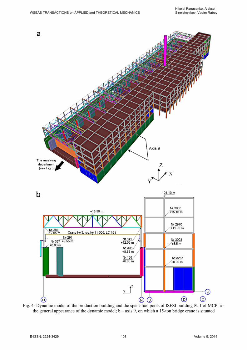
Fig. 4- Dynamic model of the production building and the spent-fuel pools of ISFSI building 1 of MCP: a -
the general appearance of the dynamic model; b – axis 9, on which a 15-ton bridge crane is situated
WSEAS TRANSACTIONS on APPLIED and THEORETICAL MECHANICSNikolai Panasenko, Aleksei Sinelshchikov, Vadim Rabey
E-ISSN: 2224-3429 108 Volume 9, 2014
or in the expanded form ( ), 1,2,...,i iW V i n= >ɺɺ
[ ] [ ][ ] [ ]
[ ] [ ][ ] [ ]
( )
0 0
0
0.
,
V VE E
M K C VV
P R V V
= + − −
+
−
ɺ
ɺɺɺ
ɺ
(5)
As opposed to the one-step methods, in (5), it is
not necessary to compute [ ] 1М
− to substantially
increase the accuracy of a computation. The solution
of equation (4) is obtained in the form of an iterative
convergent process:
(0)
1
( 1) ( ) ( )
;
( ),
n n
v v v
n n n
Z PZ
Z Z IWF Z
−
+
=
= − (6)
where nZ is the Nordsieck vector [11], which is
presented in the transposed (T) form as follows:
2 2
( )
1 1[ , , , ,..
2 6
1.., ] .
!
n n nn
n
nk k T
Z Y h Y h Y h Y
h Yk
= ɺ ɺɺ ɺɺɺ
(7)
In (6) and (7), k is the order of the Gear method (the
maximum number of the first terms of the Taylor
series of the obtained solution that coincides with an
exact solution of the differential equation of
motion); P is the Pascal triangular matrix of the
2nth-order:
1 1 1 1 1 ... 1
1 2 3 4 ...
( 1)1 3 6 ...
,... ... ... ...
( 1)1 ...
0 1
1
k
k k
k
P
k k
k
k
−
= −
(8)
I is a vector of the form 0 1, ,...,T
kI l l l= with
constant coefficients that depend on the order of the
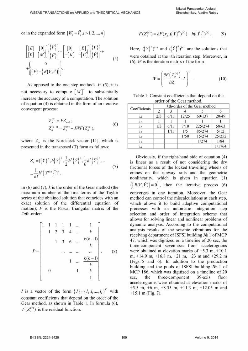
Gear method, as shown in Table 1. In formula (6), ( )( )v
nF Z is the residual function:
( ) ( ) ( )( ) ( ,( ) ) ( )
nnv v v
n nF Z hF x Y h Y= − ɺ . (9)
Here, ( )( )n vY and ( )( )
nvYɺ are the solutions that
were obtained at the vth iteration step. Moreover, in
(6), W is the iteration matrix of the form
( )1
( )v
nF ZW I
Z
− ∂ = ⋅ ∂
. (10)
Table 1. Constant coefficients that depend on the
order of the Gear method.
Coefficients kth-order of the Gear method
2 3 4 5 6
i0 2/3 6/11 12/25 60/137 20/49
i1 1 1 1 1 1
i2 1/3 6/11 7/10 225/274 58/63
i3 1/11 1/5 85/274 5/12
i4 1/50 15/274 25/252
i5 1/274 1/84
i6 1/1764
Obviously, if the right-hand side of equation (4)
is linear as a result of not considering the dry
frictional forces of the locked travelling wheels of
cranes on the runway rails and the geometric
nonlinearity, which is given in equation (1)
( )( , ) 0R V V =ɺ , then the iterative process (6)
converges in one iteration. Moreover, the Gear
method can control the miscalculations at each step,
which allows it to build adaptive computational
processes with an automatic integration step
selection and order of integration scheme that
allows for solving linear and nonlinear problems of
dynamic analysis. According to the computational
analysis results of the seismic vibrations for the
receiving department of ISFSI building 1 of MCP
47, which was digitized on a timeline of 20 sec, the
three-component seven-axis floor accelerograms
were obtained at elevation marks of +5.3 m, +10.1
m, +14.9 m, +16.8 m, +21 m, +23 m and +29.2 m
(Figs. 5 and 6). In addition to the production
building and the pools of ISFSI building 1 of
MCP 186, which was digitized on a timeline of 20
sec, the three-component 39-axis floor
accelerograms were obtained at elevation marks of
+5.5 m, +6 m, +8.55 m, +11.3 m, +12.05 m and
+15.1 m (Fig. 7).
WSEAS TRANSACTIONS on APPLIED and THEORETICAL MECHANICSNikolai Panasenko, Aleksei Sinelshchikov, Vadim Rabey
E-ISSN: 2224-3429 109 Volume 9, 2014
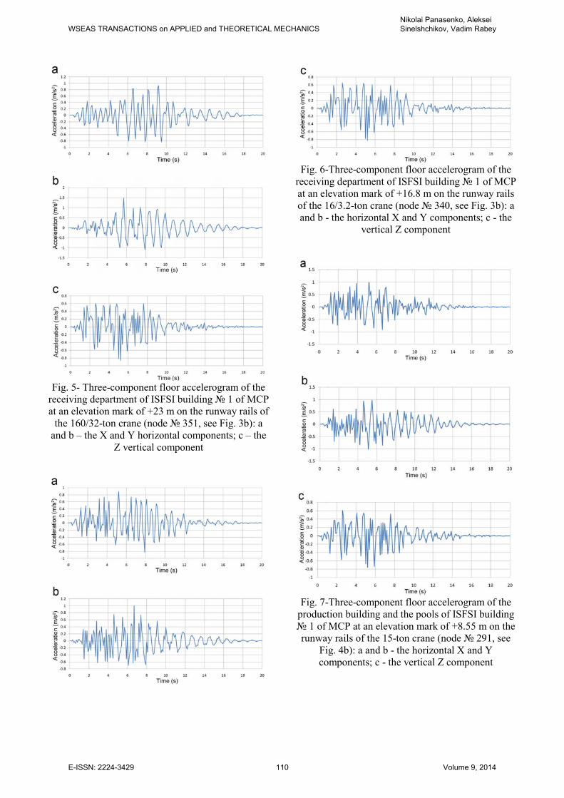
Fig. 5- Three-component floor accelerogram of the
receiving department of ISFSI building 1 of MCP
at an elevation mark of +23 m on the runway rails of
the 160/32-ton crane (node 351, see Fig. 3b): a
and b – the X and Y horizontal components; c – the
Z vertical component
Fig. 6-Three-component floor accelerogram of the
receiving department of ISFSI building 1 of MCP
at an elevation mark of +16.8 m on the runway rails
of the 16/3.2-ton crane (node 340, see Fig. 3b): a
and b - the horizontal X and Y components; c - the
vertical Z component
Fig. 7-Three-component floor accelerogram of the
production building and the pools of ISFSI building
1 of MCP at an elevation mark of +8.55 m on the
runway rails of the 15-ton crane (node 291, see
Fig. 4b): a and b - the horizontal X and Y
components; c - the vertical Z component
WSEAS TRANSACTIONS on APPLIED and THEORETICAL MECHANICSNikolai Panasenko, Aleksei Sinelshchikov, Vadim Rabey
E-ISSN: 2224-3429 110 Volume 9, 2014
4 Dynamic Models of the Cranes of the
ISFSI Building As illustrated in Fig. 8, the dynamic model of the
160/32-ton crane, which is loaded by a traverse and
a container TC-13, has n=3486 degrees of freedom
and consists of 863 FEs, which include 762 beams,
90 shells, 11 cable FEs and 581 nodes. The working
drawings of the bridge cranes ( 1, registration
number 11-003, load capacity (LC) 160/32 tons;
2, registration number 11-004, LC 16/3.2 tons;
3, registration number 11-005 and 4,
registration number 11-006, LC 15 tons) and the
working drawings of the design of containers TC-10
and TC-13, the cases, the fuel assemblies (FA) of
the VVER-1000 reactor, the traverses for TC-10 and
TC-13, the bars and the extension bars [13] were the
basic data to develop a dynamic model of the
technical systems of the crane equipment and the
technological loose gear of ISFSI under the service
load combination and the floor seismic loads.
Similarly, the dynamic model of crane 2 with
an LC of 16/3.2 tons, which is loaded by bar "B"
and case 02HM with FA, has n=3426 degrees of
freedom and consists of 847 FEs, which include 668
beams, 172 shells, 7 cable FEs and 571 nodes.
The dynamic model of crane 3, registration
number 11-005 and crane 4, registration
number 11-006, with an LC of 15 tons, which are
loaded by bars "A" and cases 02HM with FA, has
n=8310 degrees of freedom and consists of 1824
FEs, which include 1212 beams, 606 shells, 6 cable
FEs and 1385 nodes.
5 Mathematical Model of the
Probability-Statistical Floor
Accelerograms To calculate the seismic stability of the crane
systems as an input seismic action (SA), the floor
probability-statistic accelerograms were used. These
accelerograms were calculated using the floor
accelerograms of a building with independent spent
fuel storage installation (ISFSI) depending on the
installment position of the crane runway rails and
their elevation marks. The probabilistic models of
SA are the statistical average and the probability-
statistical floor accelerograms (SAFA and PSFA),
which are plotted based on an ensemble of floor
accelerograms of the receiving department, the
production building and the pools of ISFSI building
1 of MCP; the accelerograms correspond to the
same elevation marks of +23 m, +16.8 m and 8.55
m at the installment level of crane runway rails. To
plot SAFA and PSFA, the authors accepted the
following assumptions [14, 15]: 1) during the action
time eτ of the effective phase of an earthquake, 4
s≤ eτ ≤20 s, SA is a stationary random process with
zero mathematical expectation, variance 2
aσ ,
correlation function (CF) К(τ) and spectral density
function (SDF)
( )aG ω ; 2) the seismic action, which
is specified by the accelerogram а(t), has a normal
distribution with the following probability density
function:
2
2
1 (( ) exp
22 aa
a af a
σσ π
− < >= −
; (11)
3) SA is set for three spatial directions: two
horizontal X and Y directions and one vertical Z
direction, where the probability of a design-basis
earthquake (DBE) is equal to ТCR/102 and MCE is
equal to ТCR/104. The quantity ТCR is the normative
service life of a crane, which is taken (a) mediately
depending on the number of stress cycles of the
crane’s metal constructions and mechanisms
according to ISO 4301/1, (b) depending on the
importance class of the crane according to GOST
28609-90 "Load lifting cranes. Principal provisions
of calculation", (c) for general purpose cranes
according to RD 10-112-1-04[16] and (d) for cranes
of FUNE considering the requirements of NP 043-
03 [5].
We will represent SA as a random function ( )a tɶ
by ensemble of choice functions ( )ia t , none of
which describes all characteristics of SA. After
staticizing the ensemble of the initial floor
accelerograms (see Figs. 5-7), we will obtain the
action that considers all characteristics of the
ensemble. Thus, each accelerogram of the initial
ensemble is redigitized with the same step t∆ (0.01
с≤ t∆ ≤0.03 с), and for each of them, a duration is
set corresponding to duration eτ of the effective
phase of the ensemble. As a result, we have an
ensemble of accelerograms of equal duration, which
have been redigitized with equal time step and are
regarded as a realization of the random process ( )A tɶ .
For each time point tk (with digitization step t∆ ), the
instantaneous values of the earthquake process are
averaged out; i.e., the mathematical expectation
| ka t< > and the mean square value
2
| ka tσ are
determined
| ( | ) ;k i ka t a t S< >=∑
2 2
| ( | | ) ( 1) ,ka t i k ka t a t Sσ = − < > −∑ (12)
WSEAS TRANSACTIONS on APPLIED and THEORETICAL MECHANICSNikolai Panasenko, Aleksei Sinelshchikov, Vadim Rabey
E-ISSN: 2224-3429 111 Volume 9, 2014
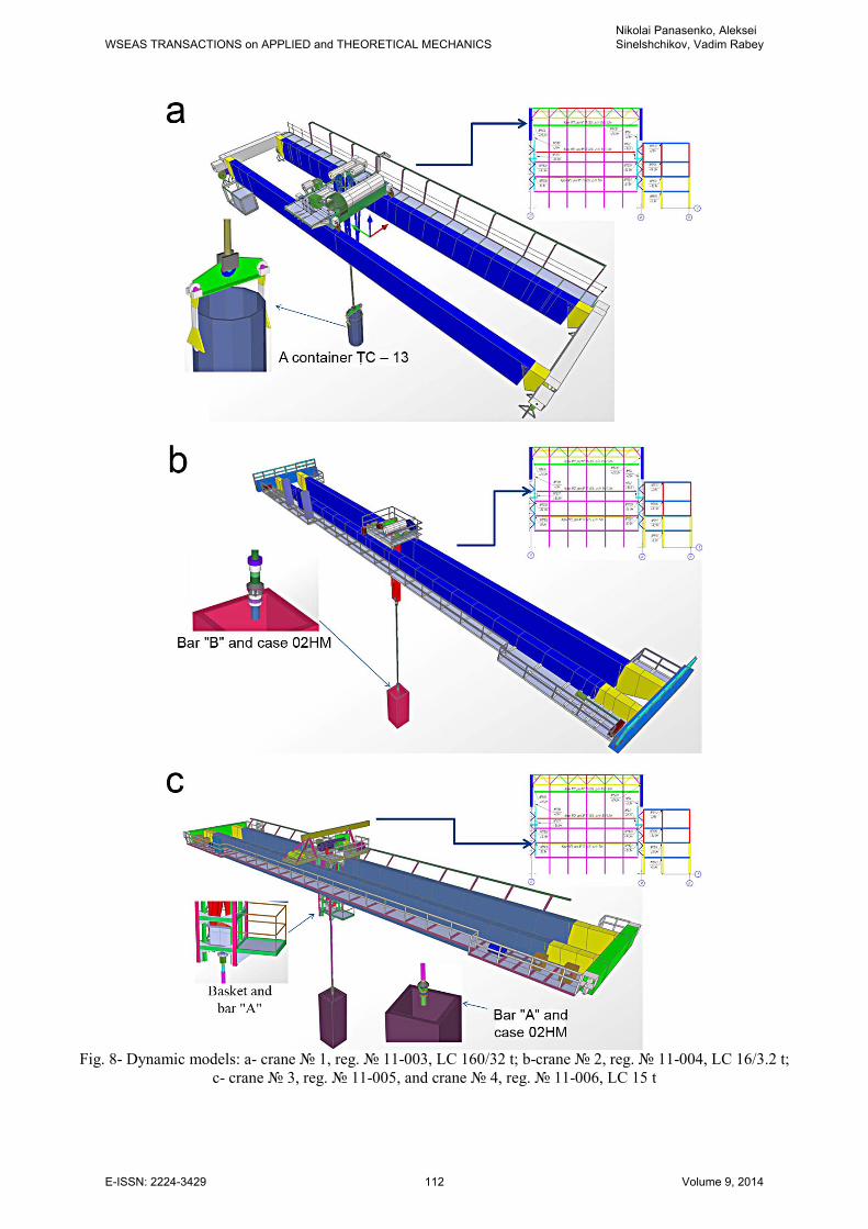
Fig. 8- Dynamic models: a- crane 1, reg. 11-003, LC 160/32 t; b-crane 2, reg. 11-004, LC 16/3.2 t;
c- crane 3, reg. 11-005, and crane 4, reg. 11-006, LC 15 t
WSEAS TRANSACTIONS on APPLIED and THEORETICAL MECHANICSNikolai Panasenko, Aleksei Sinelshchikov, Vadim Rabey
E-ISSN: 2224-3429 112 Volume 9, 2014
where S is the number of realizations of the
calculated floor seismic processes.
The sample of |i ka t of size S in (11) and (12) has
the normal distribution (11). By changing the
sample size, its mathematical expectation and
variance (12) will change. On this occasion, for the
time point tk , the value of the process | ka t< > is a
random variable with its own parameters of variance
| |k ka t a t Sσ σ< > = (13)
and mathematical expectation of the sample mean,
whose probability ( ) 2 ( )p pP F U Ф U= =
is in the
interval
|
|
( | )
( |
k
k
k p a t
k p a t
a t U S
a t U S
σ µ
σ
< > − ≤ ≤
≤ < > +, (14)
where the upper bound in (14) is SAFA:
||kk k p a ta a t U σ < >< > =< > + . (15)
In (14) and (15), ( )pF U and
( )pФ U are
tabulated functions of normal distribution
(normalized distribution and Laplace distribution);
pU is a quantile of normal distribution that
corresponds to the assumed confidence probability
P [17]. The quantile of Student’s distribution qp
should be taken with a small number of realizations
of the seismic process instead of the quantile pU in
(14) and (15).
The analysis of the floor accelerograms [9]
shows that the peak accelerations at the time point tk
of SAFA, which were built for different ensembles,
may substantially differ from each other. Thus, to
improve the accuracy of the SA presentation and the
quality of the seismic calculations of the cranes, the
authors use PSFA. Considering that the mean square
value | ka tσ in (14) is also a random variable with
confidence interval
| | |(1 ) (1 )k k kp a t a t p a tq qσ σ σ− ≤ ≤ + , (16)
where pq is a quantile of distribution and in plotting
PSFA, it is reasonable to obtain the upper bound of
the P-percentage interval of the root mean square
value of | ka tσ from (16). Afterwards, PSFA has the
form
| |[ | ] (1 )k kk k k p a t p a t pa a t U U qσ σ< >= < > + + + , (17)
which considers the P-percentage of properties of
the entire initial information of the ensemble ( )ia t ,
and PSFA can be used as a model of SA in the
calculations of the crane seismic stability using the
linear-spectral method (LSM) or DAM. It is obvious
that PSFA (17) 7, 8 and 9b on the MSK-64 scale
should be recommended to use for the practical
calculations of the cranes under SA by DAM, and
the choice of values of the confidence probability P
in (17) depends on the probability
1 Pα = − , (18)
which is called the risk of the 1st kind and
determines the range in which an α percentage of
the probable unaccounted average sample estimates
falls. For the practical calculations of the cranes
under SA, to obtain the digitalization values of the
accelerogram а(t) with any time step within the
limits of the half-cycle length, the following formula
is used
( ) sin( )ma t a Lτ πτ+ = , (19)
where L is the pulse duration, t is the pulse start
time, τ is the time within a pulse, 0≤τ<L, and аm is
the pulse amplitude.
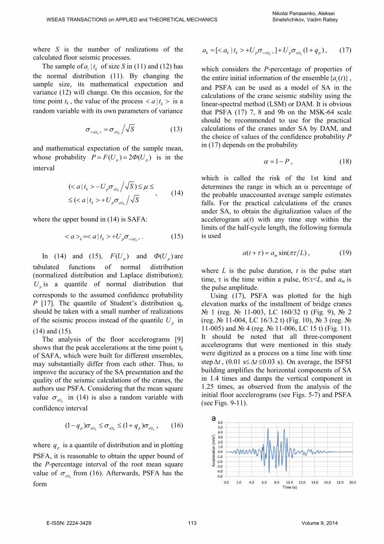
Using (17), PSFA was plotted for the high
elevation marks of the installment of bridge cranes
1 (reg. 11-003, LC 160/32 t) (Fig. 9), 2
(reg. 11-004, LC 16/3.2 t) (Fig. 10), 3 (reg.
11-005) and 4 (reg. 11-006, LC 15 t) (Fig. 11).
It should be noted that all three-component
accelerograms that were mentioned in this study
were digitized as a process on a time line with time
step t∆ , (0.01 s≤ t∆ ≤0.03 s). On average, the ISFSI
building amplifies the horizontal components of SA
in 1.4 times and damps the vertical component in
1.25 times, as observed from the analysis of the
initial floor accelerograms (see Figs. 5-7) and PSFA
(see Figs. 9-11).
WSEAS TRANSACTIONS on APPLIED and THEORETICAL MECHANICSNikolai Panasenko, Aleksei Sinelshchikov, Vadim Rabey
E-ISSN: 2224-3429 113 Volume 9, 2014
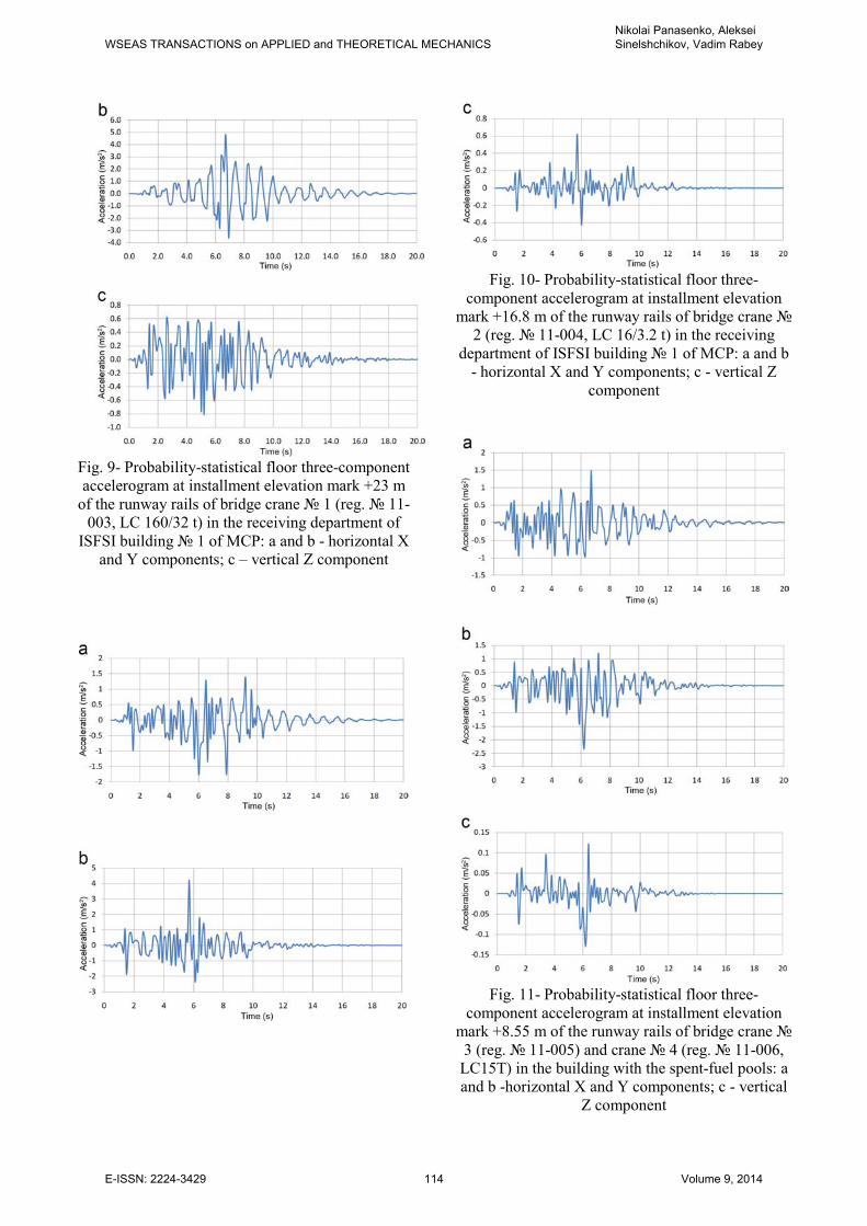
Fig. 9- Probability-statistical floor three-component
accelerogram at installment elevation mark +23 m
of the runway rails of bridge crane 1 (reg. 11-
003, LC 160/32 t) in the receiving department of
ISFSI building 1 of MCP: a and b - horizontal X
and Y components; c – vertical Z component
Fig. 10- Probability-statistical floor three-
component accelerogram at installment elevation
mark +16.8 m of the runway rails of bridge crane
2 (reg. 11-004, LC 16/3.2 t) in the receiving
department of ISFSI building 1 of MCP: a and b
- horizontal X and Y components; c - vertical Z
component
Fig. 11- Probability-statistical floor three-
component accelerogram at installment elevation
mark +8.55 m of the runway rails of bridge crane
3 (reg. 11-005) and crane 4 (reg. 11-006,
LC15T) in the building with the spent-fuel pools: a
and b -horizontal X and Y components; c - vertical
Z component
WSEAS TRANSACTIONS on APPLIED and THEORETICAL MECHANICSNikolai Panasenko, Aleksei Sinelshchikov, Vadim Rabey
E-ISSN: 2224-3429 114 Volume 9, 2014
6 Mathematical Model of the Seismic
Response Spectra The response spectra (SRS) represent a relation
between the maximum accelerations of oscillators
( ) max ( )A t x t= ɺɺ and their natural frequency (NF) ωm
(from 1 to 30 Hz) at various damping values ξ of the
metal construction of the cranes. SRS are the result
of the action of a given accelerogram a(t) (real,
synthesized, for example, SA-482[3], or PSFA,
which was calculated using formula (17)). When
SRS were given to the designer to estimate the
seismic safety of the load-lifting cranes, such
approach do not contradict clause 2.1.6 PB 10-382-
00 [18] and SNiP II-7-81* [1]. However, if there is
no SRS and they should be plotted as floor SRS
(FSRS), then PSFA must be transformed to the
standard levels (Table 2) [19].
Table 2. Maximum level of calculated accelerations
of earthquakes [19]. Seismicity, the values are
on the MSK-64 scale
5 6 7 8 9 10
Maximum level of
accelerations (m/s^2)
0.25 0.5 1 2 4 8
Therefore, to obtain the FSRS floor
accelerograms 0 ( )А τ (see Figs. 9-11), we must
numerically integrate the equation of motion of the
mth oscillator:
2
0( ) 2 ( ) ( ) ( )mx t x t x t A tξ ω+ + = −ɺɺ ɺ , (20)
where ξ is the relative damping of the crane metal
construction coefficient (ξ=0.02-0.04), which is
associated with the logarithmic decrement of
oscillations of the dynamic model of crane δd by the
following relationship [8,9,14]:
2 2 0.5[(2 ) ] / 2d d dξ δ π δ δ π−= + ≈ . (21)
Afterward, from the solution of (20), the
maximum value of reaction max( ( ))mx tɺɺ is chosen,
which is considered the response of the oscillator of
medium frequency (MF) ωm. Given zero initial
conditions, instead of equation (20), the Duhamel
integral [20] is recommended:
0
( ) (1 ) ( )exp[ ( )]
sin ( )
D D
D
t
m m
m
x t m a t
t d
ω τ ξω τ
ω τ τ
= − − ×
× −
∫ , (22)
where ωmD is the MF of the mth oscillator, which is
corrected considering damping (21):
2 2
Dm mω ω ξ= − . (23)
Obviously, the three-component SRS and FSRS
are plotted with the frequency axis up to 30 (rarely
50) Hz as a rule, where for each ωm,, a sampling
corresponds from (20) or from (22) (Figs. 12 and
13); from the three-component SRS and FSRS, we
can transition to the seismic amplification factors
(SAF) of SNiP II-7-81*[1] or RTM 108.020.37-81
[19] according to [21] if necessary.
In addition to the real SRS or FSRS, the
generalized seismic response spectra (GSRS) are of
practical concern. GSRS are spectra that were
obtained as an envelope of assemblage of SRS for a
set of real and/or synthesized accelerograms of
earthquakes [21]. As consistent with the principal
provisions of theory of the seismic stability of
buildings [1, 3, 22], where the fundamental is LSM,
it should be considered that the seismic
amplification factors (SAF) [1] were set for building
structures with logarithmic decrements of oscillation
damping dδ = 0.4, whereas dδ of the metal
constructions of the lifting equipment [23] do not
exceed dδ = 0.2 even under MCE [13]. Thus, the
algorithm of the plane problem of LSM of SNiP II-
7-81* [1] does not make it possible to study a spatial
work of beam systems of cranes under the
conditions of SA. In this connection, the authors of
this study attempt to develop the LSM of the theory
of seismic stability of the spatial constructions of
load-lifting cranes.
The basis of LSM is a conception about the
dynamic system of a crane as a collection of
independent m-oscillators, the vibration frequencies
mω of which coincide with the natural frequency
spectrum of the calculated system of a crane. Then,
the reaction of the system to SA is determined as a
sum of the maximum reactions of the oscillators that
compose the system. Examine the forced seismic
oscillations of an undamped system (a dynamic
model of a crane) with n degrees of freedom:
[ ] ( ) [ ] ( ) [ ] ( )M V t K V t M A t+ = − ɺɺɺɺ , (24)
where [M] and [K] are the mass matrix and the
stiffness matrix of the dynamic model of the crane
construction, respectively (see part 1 of the article).
In the matrix equation (24), ( )A tɺɺ is the SA vector,
which is set by PSFA (see Figs. 9-11).
WSEAS TRANSACTIONS on APPLIED and THEORETICAL MECHANICSNikolai Panasenko, Aleksei Sinelshchikov, Vadim Rabey
E-ISSN: 2224-3429 115 Volume 9, 2014
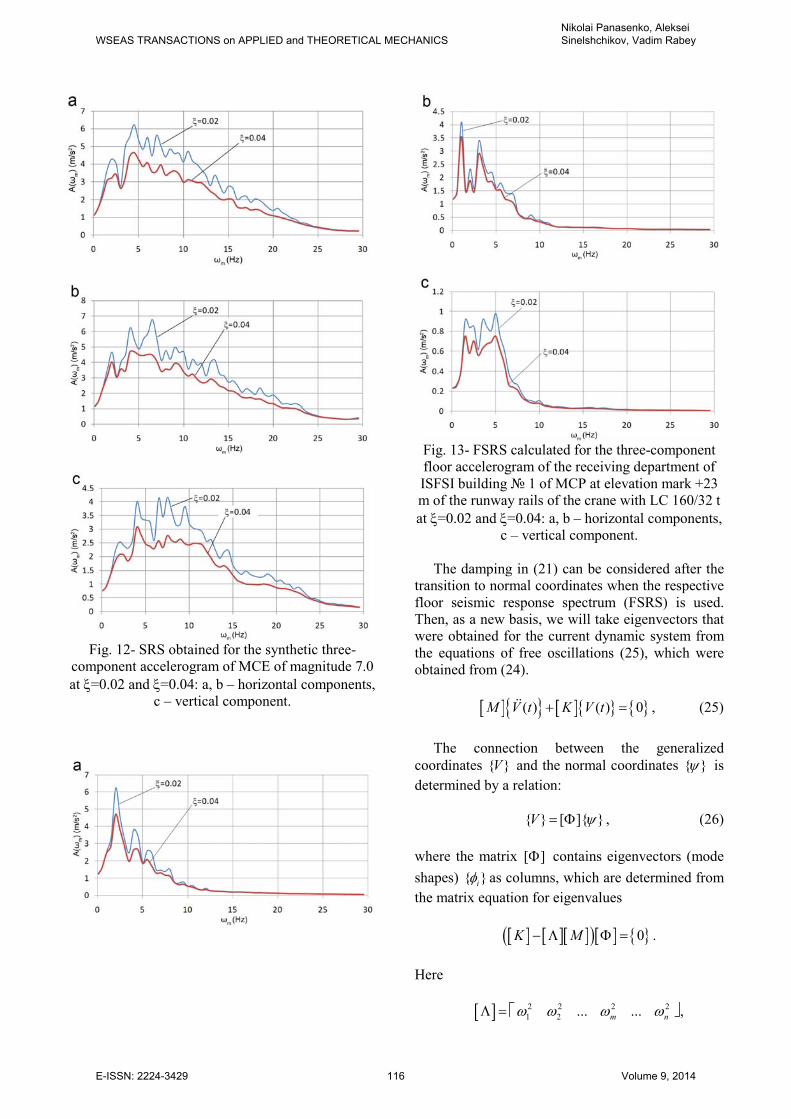
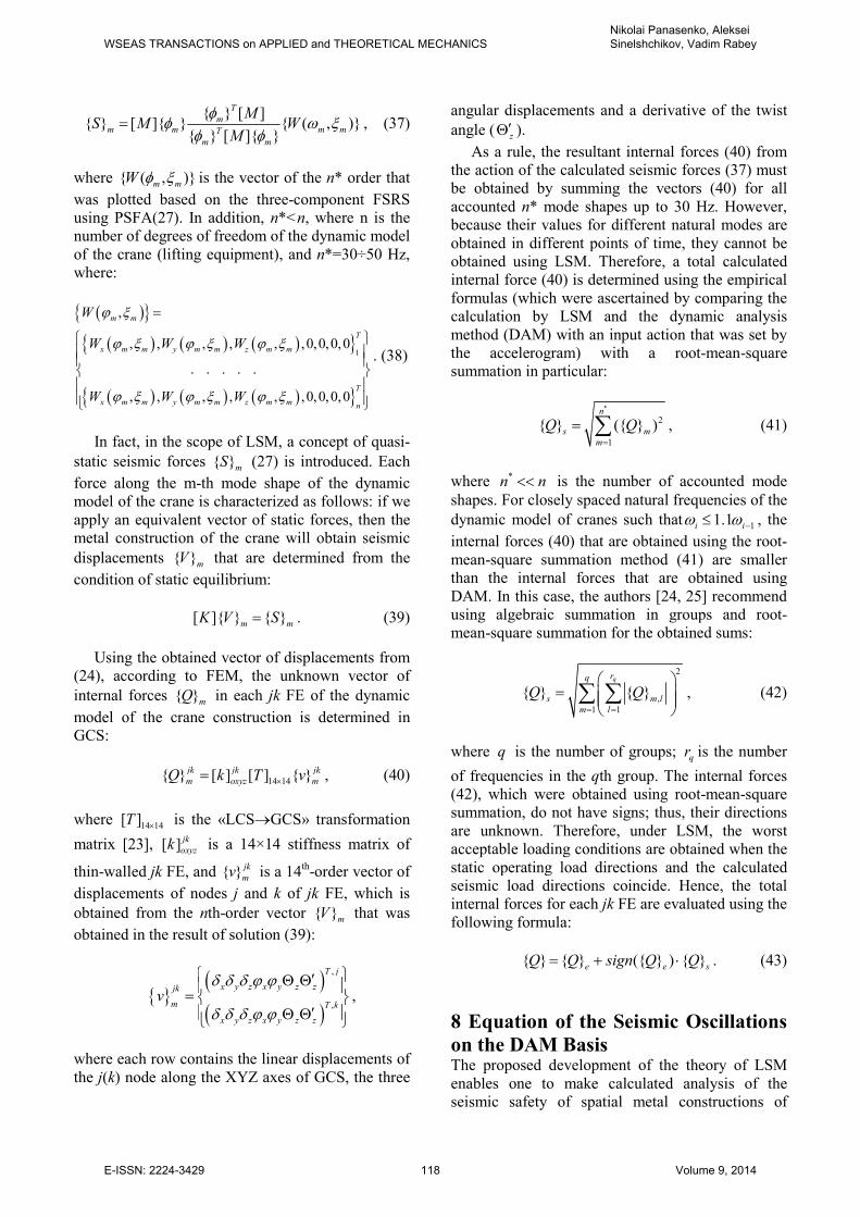
Fig. 12- SRS obtained for the synthetic three-
component accelerogram of MCE of magnitude 7.0
at ξ=0.02 and ξ=0.04: a, b – horizontal components,
c – vertical component.
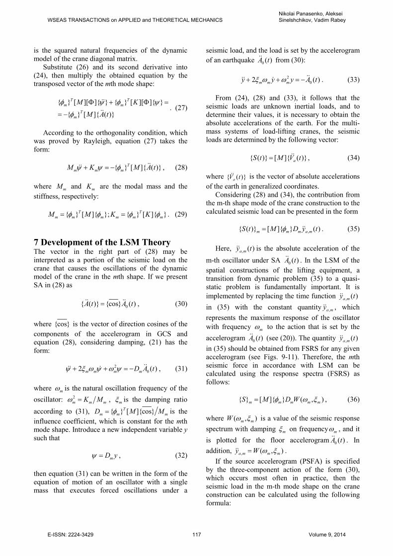
Fig. 13- FSRS calculated for the three-component
floor accelerogram of the receiving department of
ISFSI building 1 of MCP at elevation mark +23
m of the runway rails of the crane with LC 160/32 t
at ξ=0.02 and ξ=0.04: a, b – horizontal components,
c – vertical component.
The damping in (21) can be considered after the
transition to normal coordinates when the respective
floor seismic response spectrum (FSRS) is used.
Then, as a new basis, we will take eigenvectors that
were obtained for the current dynamic system from
the equations of free oscillations (25), which were
obtained from (24).
[ ] [ ] ( ) ( ) 0M V t K V t+ =ɺɺ , (25)
The connection between the generalized
coordinates V and the normal coordinates ψ is
determined by a relation:
[ ] V ψ= Φ , (26)
where the matrix [ ]Φ contains eigenvectors (mode
shapes) iφ as columns, which are determined from
the matrix equation for eigenvalues
[ ] [ ][ ]( )[ ] 0K M− Λ Φ = .
Here
[ ]Λ = 2 2 2 2
1 2 ... ...m nω ω ω ω ,
WSEAS TRANSACTIONS on APPLIED and THEORETICAL MECHANICSNikolai Panasenko, Aleksei Sinelshchikov, Vadim Rabey
E-ISSN: 2224-3429 116 Volume 9, 2014
is the squared natural frequencies of the dynamic
model of the crane diagonal matrix.
Substitute (26) and its second derivative into
(24), then multiply the obtained equation by the
transposed vector of the mth mode shape:
[ ][ ] [ ][ ]
[ ] ( )
T T
m m
T
m
M K
M A t
φ ψ φ ψ
φ
Φ + Φ =
= −
ɺɺ
ɺɺ. (27)
According to the orthogonality condition, which
was proved by Rayleigh, equation (27) takes the
form:
[ ] ( )T
m m mM K M A tψ ψ φ+ = − ɺɺɺɺ , (28)
where mM and mK are the modal mass and the
stiffness, respectively:
[ ] ; [ ] T T
m m m m m mM M K Kφ φ φ φ= = . (29)
7 Development of the LSM Theory The vector in the right part of (28) may be
interpreted as a portion of the seismic load on the
crane that causes the oscillations of the dynamic
model of the crane in the mth shape. If we present
SA in (28) as
0 ( ) cos ( )A t A t=ɺɺ ɺɺ , (30)
where cos is the vector of direction cosines of the
components of the accelerogram in GCS and
equation (28), considering damping, (21) has the
form:
2
02 ( )m m m mD A tψ ξ ω ψ ω ψ+ + = − ɺɺɺɺ ɺ , (31)
where mω is the natural oscillation frequency of the
oscillator:
2
m m mK Mω = , mξ is the damping ratio
according to (31), [ ]cosT
m m mD M Mφ= is the
influence coefficient, which is constant for the mth
mode shape. Introduce a new independent variable y
such that
mD yψ = , (32)
then equation (31) can be written in the form of the
equation of motion of an oscillator with a single
mass that executes forced oscillations under a
seismic load, and the load is set by the accelerogram
of an earthquake 0 ( )A tɺɺ from (30):
2
02 ( )m m my y y A tξ ω ω+ + = − ɺɺɺɺ ɺ . (33)
From (24), (28) and (33), it follows that the
seismic loads are unknown inertial loads, and to
determine their values, it is necessary to obtain the
absolute accelerations of the earth. For the multi-
mass systems of load-lifting cranes, the seismic
loads are determined by the following vector:
( ) [ ] ( )aS t M V t= ɺɺ , (34)
where ( )aV tɺɺ is the vector of absolute accelerations
of the earth in generalized coordinates.
Considering (28) and (34), the contribution from
the m-th shape mode of the crane construction to the
calculated seismic load can be presented in the form
, ( ) [ ] ( )m m m a mS t M D y tφ= ɺɺ . (35)
Here, , ( )a my tɺɺ is the absolute acceleration of the
m-th oscillator under SA 0 ( )A tɺɺ . In the LSM of the
spatial constructions of the lifting equipment, a
transition from dynamic problem (35) to a quasi-
static problem is fundamentally important. It is
implemented by replacing the time function , ( )a my tɺɺ
in (35) with the constant quantity ,a myɺɺ , which
represents the maximum response of the oscillator
with frequency mω to the action that is set by the
accelerogram 0 ( )A tɺɺ (see (20)). The quantity , ( )a my tɺɺ
in (35) should be obtained from FSRS for any given
accelerogram (see Figs. 9-11). Therefore, the mth
seismic force in accordance with LSM can be
calculated using the response spectra (FSRS) as
follows:
[ ] ( , )m m m m mS M D Wφ ω ξ= , (36)
where ( , )m mW ω ξ is a value of the seismic response
spectrum with damping mξ on frequency mω , and it
is plotted for the floor accelerogram 0 ( )A tɺɺ . In
addition, , ( , )a m m my W ω ξ=ɺɺ .
If the source accelerogram (PSFA) is specified
by the three-component action of the form (30),
which occurs most often in practice, then the
seismic load in the m-th mode shape on the crane
construction can be calculated using the following
formula:
WSEAS TRANSACTIONS on APPLIED and THEORETICAL MECHANICSNikolai Panasenko, Aleksei Sinelshchikov, Vadim Rabey
E-ISSN: 2224-3429 117 Volume 9, 2014
[ ] [ ] ( , )
[ ]
T
mm m m mT
m m
MS M W
M
φφ ω ξ
φ φ= , (37)
where ( , )m mW φ ξ is the vector of the n* order that
was plotted based on the three-component FSRS
using PSFA(27). In addition, n*<n, where n is the
number of degrees of freedom of the dynamic model
of the crane (lifting equipment), and n*=30÷50 Hz,
where:
( )
( ) ( ) ( )
( ) ( ) ( )
1
,
, , , , , ,0,0,0,0
. . . . .
, , , , , ,0,0,0,0
m m
T
x m m y m m z m m
T
x m m y m m z m m n
W
W W W
W W W
ϕ ξ
ϕ ξ ϕ ξ ϕ ξ
ϕ ξ ϕ ξ ϕ ξ
=
. (38)
In fact, in the scope of LSM, a concept of quasi-
static seismic forces mS (27) is introduced. Each
force along the m-th mode shape of the dynamic
model of the crane is characterized as follows: if we
apply an equivalent vector of static forces, then the
metal construction of the crane will obtain seismic
displacements mV that are determined from the
condition of static equilibrium:
[ ] m mK V S= . (39)
Using the obtained vector of displacements from
(24), according to FEM, the unknown vector of
internal forces mQ in each jk FE of the dynamic
model of the crane construction is determined in
GCS:
14 14 [ ] [ ] jk jk jk
m oxyz mQ k T v×= , (40)
where 14 14[ ]T × is the «LCS→GCS» transformation
matrix [23], [ ] jk
oxyzk is a 14×14 stiffness matrix of
thin-walled jk FE, and jk
mv is a 14th-order vector of
displacements of nodes j and k of jk FE, which is
obtained from the nth-order vector mV that was
obtained in the result of solution (39):
( )( )
,
,
T j
x y z x y z zjk
m T k
x y z x y z z
vδ δ δ ϕ ϕ
δ δ δ ϕ ϕ
′Θ Θ =
′ Θ Θ
,
where each row contains the linear displacements of
the j(k) node along the XYZ axes of GCS, the three
angular displacements and a derivative of the twist
angle ( z′Θ ).
As a rule, the resultant internal forces (40) from
the action of the calculated seismic forces (37) must
be obtained by summing the vectors (40) for all
accounted n* mode shapes up to 30 Hz. However,
because their values for different natural modes are
obtained in different points of time, they cannot be
obtained using LSM. Therefore, a total calculated
internal force (40) is determined using the empirical
formulas (which were ascertained by comparing the
calculation by LSM and the dynamic analysis
method (DAM) with an input action that was set by
the accelerogram) with a root-mean-square
summation in particular:
*
2
1
( )n
s m
m
Q Q=
= ∑ , (41)
where *n n<< is the number of accounted mode
shapes. For closely spaced natural frequencies of the
dynamic model of cranes such that 11.1i iω ω −≤ , the
internal forces (40) that are obtained using the root-
mean-square summation method (41) are smaller
than the internal forces that are obtained using
DAM. In this case, the authors [24, 25] recommend
using algebraic summation in groups and root-
mean-square summation for the obtained sums:
2
,
1 1
qrq
s m l
m l
Q Q= =
=
∑ ∑ , (42)
where q is the number of groups; qr is the number
of frequencies in the qth group. The internal forces
(42), which were obtained using root-mean-square
summation, do not have signs; thus, their directions
are unknown. Therefore, under LSM, the worst
acceptable loading conditions are obtained when the
static operating load directions and the calculated
seismic load directions coincide. Hence, the total
internal forces for each jk FE are evaluated using the
following formula:
( ) e e sQ Q sign Q Q= + ⋅ . (43)
8 Equation of the Seismic Oscillations
on the DAM Basis The proposed development of the theory of LSM
enables one to make calculated analysis of the
seismic safety of spatial metal constructions of
WSEAS TRANSACTIONS on APPLIED and THEORETICAL MECHANICSNikolai Panasenko, Aleksei Sinelshchikov, Vadim Rabey
E-ISSN: 2224-3429 118 Volume 9, 2014
cranes. However, the proposed methodology
overrates the internal forces (43) by 20-25% on
average and consequently overrates the specific
metal quantity of cranes in the seismic stability of
the crane design (according to the requirements of
PB 10-382-00 [18]). Thus, the authors of the present
study find it necessary to apply a further
methodological transition from LSM to the DAM
[23] mathematical model, which is a matrix of
differential equations of motion of the nth order of
the form
[ ] ( ) [ ] ( ) [ ] ( ) ( ) ( )( ) [ ], ( ( )).ST
M V t C V t K V t
R V t V t R M cos A t
+ + +
+ = −
ɺɺ ɺ
ɺɺɺ (44)
Assuming that the reader is familiar with the
nonlinear equation of seismic oscillations of the
spatial constructions of cranes (44), we should dwell
on two factors. The first factor is associated with the
formulation of the damping matrix. In the linear
equations of motion (44) (for ( , ) 0R V V =ɺ ), the
recommended form of the damping matrix is
proportional to the mass matrix and the stiffness
matrix of the calculated system:
[ ] [ ] [ ] [ ] [ ]M KC M Kα α= + , (45)
where the constants of proportionality
[ ] ,1 1( ) /dM
α δ ω π= ; [ ] ,1 1К/dα δ πω= ,
depend on the decrement ,1dδ (see formula (21))
and the frequency 1ω of the lowest natural mode
shape of the construction elements of the crane
dynamic model. The recommendations to determine
,1dδ may be found in [23, 24, 26]. Moreover, (45) is
used extensively in the computational practice
damping matrix with frequency-independent
internal friction of A. I. Tseitlin [27]:
[ ] [ ] [ ] [ ]( ) [ ]
0.51
С М М К Г−
= , (46)
where [ ]Г is the (damped) loss matrix. For
homogeneous constructions such as the sheet-
welded metal constructions of bridge cranes
[ ] /d dГ γ δ π= = . (47)
Along with (37),
24 / 4dγ γ γ= − , (48)
where γ is the coefficient of internal friction of
Sorokin E.S. [28]. From (48), one can see
that dγ γ≈ ; thus, matrix (46) is transformed to the
less popular damping matrix of V.T. Rasskazovski
and A.I. Martemjanov [29]
[ ] [ ][ ]( )0.5
dС М Кγ= . (49)
The second factor concerns the determination of
the node internal forces in the end sections of the
finite elements of the crane dynamic model after
solving the matrix equation (44) and calculating the
vector of unknown displacements 1( ) nV t × in the
general coordinate system oxyz.
9 Seismic Safety Criterion of the
Load-Lifting Cranes in Buildings with
Crane Loadings The known vector of internal forces at the ends of
the jk element in the local coordinate system oxyz
has the following structure
( )
( )
Т
14 1 Т
x y z x y zjk j
x y z x y z k
Q Q N M M M BQ
Q Q N M M M B×
=
, (50)
and it is a result of shear deformation, tension-
compression, bending, torsion and deplanation,
where B is the bimoment known from the theory of
thin-walled bars of Vlasov and Umanski [30]. If
( )jk
OXYZV t are the node displacements of the jk
finite element in the general coordinate system, then
its node internal forces ( )jk
oxyzQ t in the local
coordinate system oxyz will be calculated from the
following equation
[ ] [ ] ( )
14 14 14 14( ) (
,
)oxyzjk jk
oxyz OXYZjk
jk
p oxyz
Q t K T V t
R
× ×= +
+ (51)
where [ ] 14 14
oxyz
jkK
× is the deformational stiffness
matrix of the jk finite element in the local coordinate
system oxyz, jk
p oxyzR is the summation vector of the
WSEAS TRANSACTIONS on APPLIED and THEORETICAL MECHANICSNikolai Panasenko, Aleksei Sinelshchikov, Vadim Rabey
E-ISSN: 2224-3429 119 Volume 9, 2014
reaction external actions, and [ ]14 14
T×
is the
transformation matrix as mentioned in (51) [31].
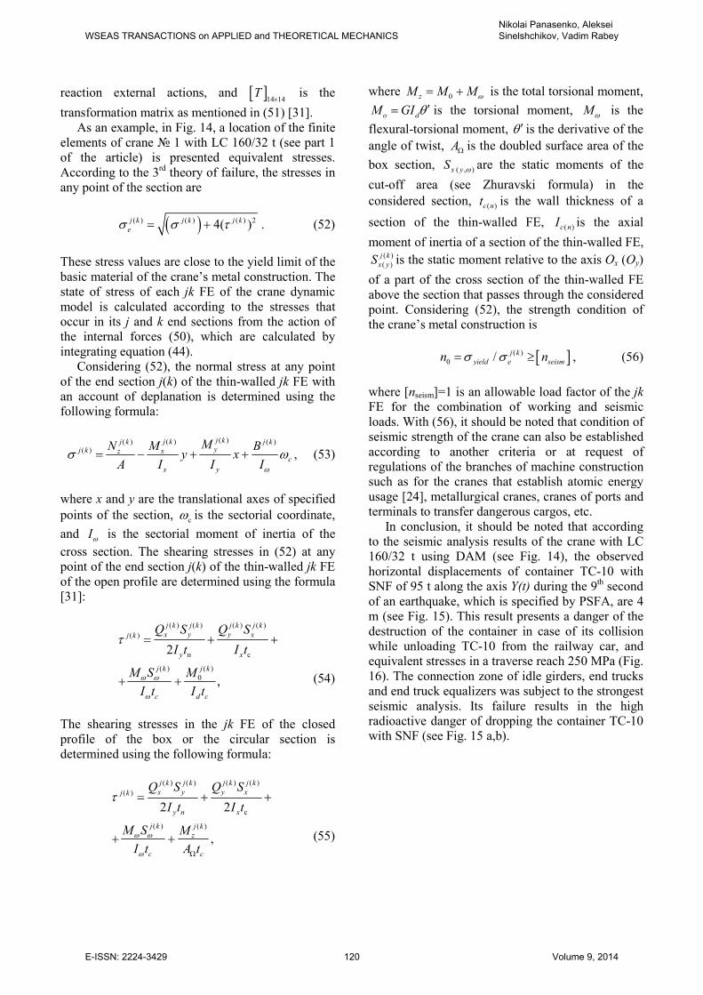
As an example, in Fig. 14, a location of the finite
elements of crane 1 with LC 160/32 t (see part 1
of the article) is presented equivalent stresses.
According to the 3rd
theory of failure, the stresses in
any point of the section are
( )( ) ( ) ( ) 24( )j k k k
e
j jσ σ τ= + . (52)
These stress values are close to the yield limit of the
basic material of the crane’s metal construction. The
state of stress of each jk FE of the crane dynamic
model is calculated according to the stresses that
occur in its j and k end sections from the action of
the internal forces (50), which are calculated by
integrating equation (44).
Considering (52), the normal stress at any point
of the end section j(k) of the thin-walled jk FE with
an account of deplanation is determined using the
following formula:
( )( )( ) ( )
( )
j kj kj k j kyj k xz
c
x y
MMN By x
A I I Iω
σ ω= − + + , (53)
where x and y are the translational axes of specified
points of the section, сω is the sectorial coordinate,
and Iω is the sectorial moment of inertia of the
cross section. The shearing stresses in (52) at any
point of the end section j(k) of the thin-walled jk FE
of the open profile are determined using the formula
[31]:
( ) ( ) ( ) ( )
( )
п с
( ) ( )
0
2
,
j k j k j k j k
x y y xj k
y x
j k j k
dc c
Q S Q S
I t I t
M S M
I t I t
ω ω
ω
τ = + +
+ + (54)
The shearing stresses in the jk FE of the closed
profile of the box or the circular section is
determined using the following formula:
( ) ( ) ( ) ( )
( )
с
( ) ( )
2 2
,
j k j k j k j k
x y y xj k
y n x
j k j k
z
c с
Q S Q S
I t I t
M S M
I t A t
ω ω
ω
τ
Ω
= + +
+ +
(55)
where 0zM M Mω= + is the total torsional moment,
o dM GI θ ′= is the torsional moment,
Mω is the
flexural-torsional moment, θ ′ is the derivative of the
angle of twist,
АΩ is the doubled surface area of the
box section, ( , )x yS ω are the static moments of the
cut-off area (see Zhuravski formula) in the
considered section, ( )c nt is the wall thickness of a
section of the thin-walled FE, ( )c nI is the axial
moment of inertia of a section of the thin-walled FE, ( )
( )
j k
x yS is the static moment relative to the axis Oх (Oу)
of a part of the cross section of the thin-walled FE
above the section that passes through the considered
point. Considering (52), the strength condition of
the crane’s metal construction is
[ ]( )
0 / j k
eyield seismn nσ σ= ≥ , (56)
where [nseism]=1 is an allowable load factor of the jk
FE for the combination of working and seismic
loads. With (56), it should be noted that condition of
seismic strength of the crane can also be established
according to another criteria or at request of
regulations of the branches of machine construction
such as for the cranes that establish atomic energy
usage [24], metallurgical cranes, cranes of ports and
terminals to transfer dangerous cargos, etc.
In conclusion, it should be noted that according
to the seismic analysis results of the crane with LC
160/32 t using DAM (see Fig. 14), the observed
horizontal displacements of container TC-10 with
SNF of 95 t along the axis Y(t) during the 9th second
of an earthquake, which is specified by PSFA, are 4
m (see Fig. 15). This result presents a danger of the
destruction of the container in case of its collision
while unloading TC-10 from the railway car, and
equivalent stresses in a traverse reach 250 MPa (Fig.
16). The connection zone of idle girders, end trucks
and end truck equalizers was subject to the strongest
seismic analysis. Its failure results in the high
radioactive danger of dropping the container TC-10
with SNF (see Fig. 15 a,b).
WSEAS TRANSACTIONS on APPLIED and THEORETICAL MECHANICSNikolai Panasenko, Aleksei Sinelshchikov, Vadim Rabey
E-ISSN: 2224-3429 120 Volume 9, 2014
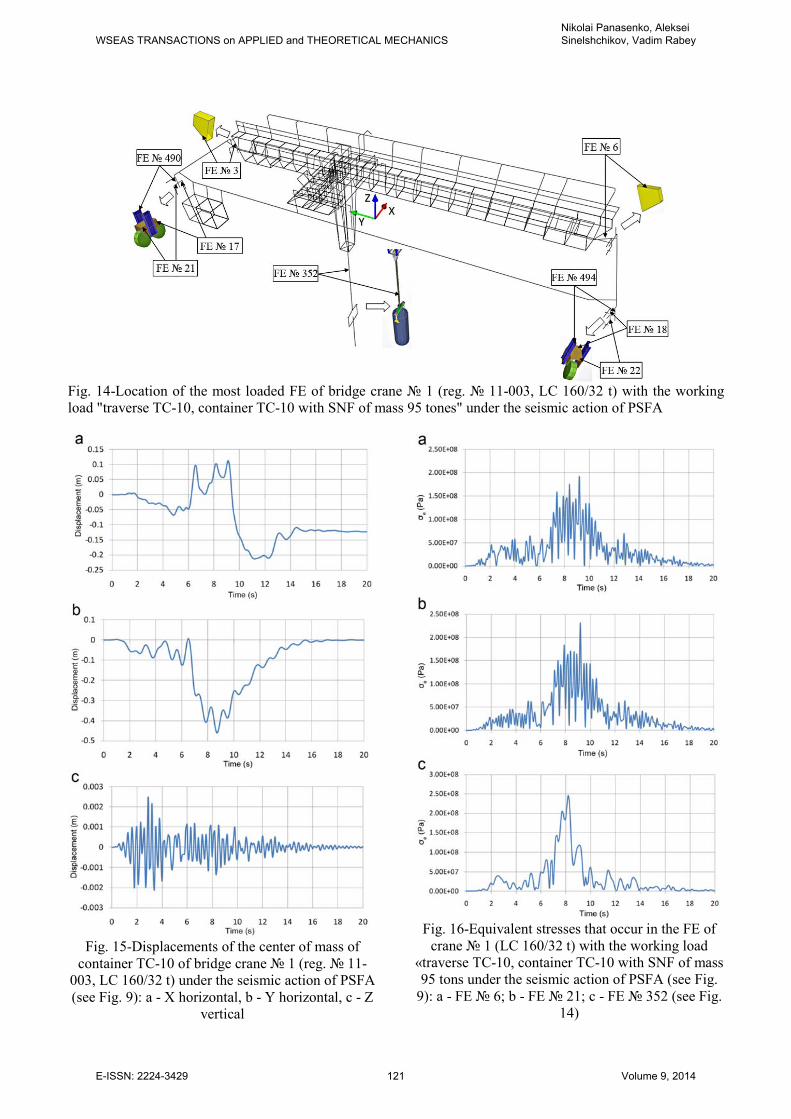
Fig. 14-Location of the most loaded FE of bridge crane 1 (reg. 11-003, LC 160/32 t) with the working
load "traverse TC-10, container TC-10 with SNF of mass 95 tones" under the seismic action of PSFA
Fig. 15-Displacements of the center of mass of
container TC-10 of bridge crane 1 (reg. 11-
003, LC 160/32 t) under the seismic action of PSFA
(see Fig. 9): a - X horizontal, b - Y horizontal, c - Z
vertical
Fig. 16-Equivalent stresses that occur in the FE of
crane 1 (LC 160/32 t) with the working load
«traverse TC-10, container TC-10 with SNF of mass
95 tons under the seismic action of PSFA (see Fig.
9): a - FE 6; b - FE 21; c - FE 352 (see Fig.
14)
WSEAS TRANSACTIONS on APPLIED and THEORETICAL MECHANICSNikolai Panasenko, Aleksei Sinelshchikov, Vadim Rabey
E-ISSN: 2224-3429 121 Volume 9, 2014
10 Conclusion The standardization of calculated seismic effects on
the industrial buildings of nuclear energy facilities
(FUNE) with crane loadings was proposed
according to the maps of general seismic
regionalization OSR-97. A discrete-continuum shell-beam dynamic model
of the ISFSI building with cranes and crane loadings
from cranes with 160/32 t, 16/3.2 t and 15 t was
developed based on the FEM principals.
For the dynamic model of the ISFSI building
with crane loadings in the 7 magnitude zone, a non-
linear equation of the nth-order seismic oscillations
was developed. The equation was solved using the
absolutely stable Gear method with the backward
differentiation formula. As a result, many calculated
floor accelerograms were obtained for the seismic
analysis of the subsystems of the ISFSI building and
the load-lifting cranes.
For separate levels of the building and zones of
crane operation, the calculated probability-statistical
floor accelerograms were plotted. The dynamic
properties of the ISFSI building was analyzed in the
filtration regime of the seismic actions from the
ground level to some elevation marks of the ISFSI
building.
In accordance with the basic provisions of the
theory of seismic stability of structures [1] and the
levels of seismic accelerations of 1, 2, 4 and 8 m/s^2
for the 7, 8, 9 and 10 magnitude zones with the
damping of the ISFSI building with crane loadings,
the floor seismic response spectrum were plotted.
The plots are an application by the authors to
develop the linear-spectral theory of the spatial
shell-beam systems compared to the plane model in
[1].
The basics of the theory of seismic stability of
the spatial structures of industrial buildings with
cranes and crane loadings were proposed based on
FEM and DAM by integrating the seismic
oscillation equations using the Gear method and the
LSM equations of motion, which are solved in
principal coordinates by applying the orthogonality
conditions of Rayleigh.
The seismic oscillation equations were solved
using DAM and LSM for the ISFSI building with
crane loadings. The transition from the
displacements to the internal forces and then to the
normal and tangent stresses was proposed, which is
used by the designer to make decisions according to
the chosen strength theory.
References:
[1] Construction in Seismic Areas, SNiP II-7-81*
Standard, 2000 (in Russian).
[2] Safety Regulations for Storage and
Transportation of Nuclear Fuel at Nuclear
Facilities, NP 061-05 Standard, 2005 (in
Russian).
[3] Aseismic Nuclear Power Plants Design Code,
NP 031-01 Standard, 2001 (in Russian).
[4] Carrying Out of Complex Engineering-Seismic
Works at a ISFSI Building 1 Site of the MCP,
Volume 4: Seismic Zoning and Development
of Synthesized Accelerograms According to
Soil Characteristics Under Foundation of the
ISFSI Building 1, Moscow: IGE RAS, 2006
(in Russian).
[5] Requirements to Arrangement and Safe
Operation of Load - Lifting Cranes at Nuclear
Power Plants, NP 043-03 Standard, 2003 (in
Russian).
[6] General Provisions for Safety of Nuclear Fuel
Cycle Plants, NP 016-05 Standard, 2005 (in
Russian).
[7] Determination of Initial Seismic Vibrations of
Soil for Design Basis, RB 006-98 Standard,
1998 (in Russian).
[8] N. Panasenko, Dynamics and Seismic Stability
of Lifting-and-Transport Equipments of
Nuclear Power Plants, Part 1, Ph.D.
dissertation, Dept. Load-Lifting Machines,
NPI, Novocherkassk, 1992 (in Russian).
[9] A. Sinelshchikov, Dynamics and Seismic
Stability of Bridge Cranes, Candidate of
Science dissertation, Dept. Load-Lifting
Machines, ASTU, Astrakhan, 2000 (in
Russian).
[10] A. Arushanyan, S. Zaletkin, Numerical
Solution of Ordinary Differential Equations
Using FORTRAN, Moscow: MSU, 1990 (in
Russian).
[11] C. Gear, Numerical Initial Value Problems in
Ordinary Differential Equations, N.J.: Prentice
- Hall, 1971.
[12] V. Myachenkov, Calculation of Machinery
Structures by FEM, Moscow: Mashinostroenie,
1989 (in Russian).
[13] N. Panasenko, A. Sinelshchikov, Technical
Safety of Shipping Packaging Sets for Spent
Nuclear Fuel, Lifting-and-Transport
Equipments (Ukraine), Vol.27, 3, 2008, pp.
55-83 (in Russian).
[14] V. Kotelnikov, N. Panasenko, A.
Sinelshchikov, Development of an Earthquake
Model for a Calculating Analysis of Seismic
WSEAS TRANSACTIONS on APPLIED and THEORETICAL MECHANICSNikolai Panasenko, Aleksei Sinelshchikov, Vadim Rabey
E-ISSN: 2224-3429 122 Volume 9, 2014
Stability of Lifting Structures, Work Safety in
Industry, 9, 2007, pp. 42-46 (in Russian)
[15] A. Sinelshchikov, N. Panasenko, Spectral
Analysis of Seismic Impact in the Theory of
Seismic Stability of Hoisting Units, Vestnik
ASTU, Vol. 43, 2, 2008, pp. 27-34 (in
Russian).
[16] Recommendations on Expert Inspection of
Load - Lifting Machines, General Provisions,
RD 10-112-1-04 Standard, 2002 (in Russian)
[17] S. Poljakov, Aseismic Building Structures,
Moscow: Vysshaia Shkola, 1983 (in Russian).
[18] Regulations on Arrangement and Safe
Operation of Load - Lifting Cranes, PB10-382-
00 Standard, 2000 (in Russian).
[19] Equipment of Nuclear Power Plants, A
Strength Calculation Under Seismic Action,
RTM 108.020.37-81 Standard, 1981 (in
Russian).
[20] R. W. Clough, J. Penzien, Dynamics of
Structures, Boston: McGraw-Hill, 1975.
[21] V. Rasskazovski, I. Aliev, Seismic Actions on
Hydrotechnical and Energy Structures,
Moscow: Nauka, 1981 (in Russian).
[22] Nuclear Power Plants – Design Against
Seismic Hazards , ISO 6258-85 Standard, 1985
[23] Regulations for Calculation of Load - Lifting
Cranes’ Spatial Metal Constructions Under
Operational and Seismic Actions at Nuclear
Power Plants, RD 24.090.83-87 Standard,
1988 (in Russian).
[24] A. H. Hadjian, S. F. Masri, A. F. Saud, A
Review of Methods of Equivalent Damping
Estimation From Experimental Data, Journal of
Pressure Vessel Technology, Vol. 109, 2,
1987, pp. 236-243.
[25] A. Ceitlin, About Taking into Account an
Internal Friction in Standards on Dynamic
Calculation of Structures, Structural Mechanics
and Calculation of Constructions, 4, 1981,
pp. 33-37 (in Russian).
[26] E. Sorokin, About Inaccuracies of a Well -
Known Method in the Theory of Oscillation of
Dissipative Systems in Application to Non-
Uniform Damping, Structural Mechanics and
Calculation of Constructions, 2, 1984, pp.
29-34 (in Russian).
[27] V. Rasskazovski, Physical Methods
Foundations for Determination of Seismic
Actions, Tashkent: Fun, 1973 (in Russian).
[28] N. Panasenko, S. Bozhko, Aseismic Lifting-
Transport Machines of Nuclear Power Plants,
Krasnoyarsk: KSU, 1987 (in Russian).
[29] Regulations on Strength Calculation of
Equipment and Pipelines of Nuclear Power
Installations, PNAE G-7-002-86 Standard,
1989 (in Russian).
[30] V. Slivker, Structural Mechanics: Basic
Variational Principles, Moscow: ASV, 2005
(in Russian).
[31] A. Birbraer, S. Shulman, Strength and
Reliability of Constructions of Nuclear Power
Plants Under Special Dynamic Loads,
Moscow: Energoatomizdat, 1989 (in Russian).
WSEAS TRANSACTIONS on APPLIED and THEORETICAL MECHANICSNikolai Panasenko, Aleksei Sinelshchikov, Vadim Rabey
E-ISSN: 2224-3429 123 Volume 9, 2014


![JUSTIFICATION TOOLKIT - ubmemeaensoprod.s3.amazonaws.com€¦ · F ORMA TTENDIN AC .PHAMAPACKEUROPE.COM JUSTIFICATION TOOLKIT Justification Letter Template Dear [Name]: I am writing](https://img.pdfslide.net/doc/110x75/5e176177a9d5b249e5069d31/justification-toolkit-ubmemeaensoprods3-f-orma-ttendin-ac-phamapackeuropecom.jpg)