Embed Size (px)
Citation preview
Geomatics, Landmanagement and Landscape No. 3 • 2014, 7–15GLL
THE CALCULATION OF RECEIVED OPTICAL POWER DURING AIRBORNE LASER SCANNING OF WATER OBJECT
Andriy Babushka, Khrystyna Burshtynska, Lyubov Babiy
Summary
In this paper calculation of some physical parameters of the receiver of laser scanning system is presented. Basic physical principles of laser scanning of water objects are considered. Ranging standard deviation for typical parameters of laser scanning system are calculated. Formula for calculation of reflected optical power for specular reflective objects is proposed.
Keywords
specular reflection • water surface • avalanche photodiode • signal to noise ratio • ranging stand-ard deviation
1. Introduction
In recent years landscape mapping and solution of different applied problems airborne laser scanning is actively used. The main advantages of this method are high efficiency, accuracy, availability to implement the surveying in night time and quick obtaining of final results. The determination of point coordinates with high accuracy depends on following factors:• surveying – fly height, beam divergence, location of the reflected point within the
swathe,• precision of determining of exterior orientation elements – GPS satellite geometry,
distance to ground base station, IMU update frequency and resolution,• atmosphere influence – aerosols availability and turbulence,• technique of classification and data processing.
Application of airborne laser scanning for investigation of area with large number of water objects often does not give fine informational content results. Water has prop-erties of reflection of laser beam. It is specular reflection of water surface and high absorption in near infrared wavelength (with this wavelength all commercial topo-graphic airborne laser scanners work). Shortage of measured points in water surface and reducing them in wetlands leads to complication of the creation of digital surface model with high accuracy [Brzank and Heipke 2007].
A. Babushka, K. Burshtynska, L. Babiy
http://dx.doi.org/10.15576/GLL/2014.3.7

A. Babushka, K. Burshtynska, L. Babiy8
GLL No. 3 • 2014
The following reasons influence reducing value of laser pulse during transmission to object and return direction: absorption and scattering by the atmosphere, reflectivity of target, distance to the target and losses of receiving system. It should be noted, that atmosphere influence on reducing laser pulse twice as a laser beam transmit double way – from transmitter to the target and backward.
For investigation of water objects and mapping of bottom of shallow water basins (not deeper than 70 m) in last years bathymetric laser systems are actively used. Using two lasers with near infrared (1064 nm) and green (532 nm) wavelengths [Shan and Toth 2008] gives possibility to detect the depth, as green laser beam penetrates through water and reflects from the bottom. Such systems are more complicated and expensive and, therefore, less widespread. Besides, accuracy parameters of detecting coordinates of points on land are considerably worse than in topographic laser systems.
The main tasks of investigation are: to calculate value of reflected optical power from the water and land surface in different conditions; to determine possibility of receiver to detect received energy as reflected signal; to consider a question of determi-nation of signal to noise ratio (SNR) of receiver.
2. Physical principles of laser scanning of water objects
If specular reflection occurs, only beams with angles of incident close to zero will come back to the receiver and can be fixed. For larger angles signal will be lost completely as a result of specular reflection. In real conditions any water surface is always rough and reflection occurs for larger angles too. This is because only some part of all area of illuminated surface can be located perpendicular to the beam (Figure 1). With increas-ing an angle of incident, the probability of such mutual disposition reduces. Therefore on the edges of scan strip we usually have very small part of measured points and they have very small intensity.
Source: authors’ study
Fig. 1. Reflection of laser beam from the water in case of: a) horizontal surface, b) rough surface with α ≠ β, c) rough surface with β = 0

THE CALCULATION OF RECEIVED OPTICAL POWER... 9
Geomatics, Landmanagement and Landscape No. 3 • 2014
In real conditions we can see two main cases – total absence of measured points on surface of water as a result of specular reflection and absorption (Figure 2a) or partial availability of points in places, where air carrier was flighting directly above basin (Figure 2b).
a) b)
Source: authors’ study
Fig. 2. Peculiarities of laser beams reflection from water surface: a) absence of measured points, b) partial availability of measured points
3. Calculation of the main parameters of the receiver
3.1. Calculation of reflected energy
For obtaining mathematical expression of reflected optical power PR from the water surface we use equation for diffuse reflected surface [Brenner and et. 2006]. When taking into account the losses in receiving optics, the level of reflected signal will be reduced. Therefore, we have to take into consideration the system transmission factor ηsys. Then we can write the equation:
P = A P M
RRr T
sysrp
h⋅⋅ ⋅
⋅2
22, (1)
where: PT – transmitted optical power, ρ – reflectivity of target, Ar – area of receiver aperture, R – range from sensor to target, M – atmospheric transmission factor, ηsys – system transmission factor.

A. Babushka, K. Burshtynska, L. Babiy10
GLL No. 3 • 2014
As we can see from the formula, the power of received pulse is directly proportional to the transmitted optical power and inversely proportional to the square of range from sensor to target.
In case of specular reflection laser light will be scattering not in solid angle of hemi-
sphere 2π, but in angle equal W=R
R,
p b24
12
2
⋅( )
⋅ where:
p b24
2R ⋅( ) – the part of
hemisphere area, in which reflected beam will be scattering; β – the divergence of the laser beam in radians. From here Ω = π · β2. For calculation of part of hemisphere area, in which reflected beam will be scattering, for large R, the value Dtar can be neglected in comparison to R · β (Figure 3).
Source: authors’ study
Fig. 3. Geometry of laser beam spreading that has been emitted by the laser rangefinder to the target and on its return direction (incidence angle 0°)
Therefore formula PR becomes
P = A P M
RRr T
sysrp b
h⋅⋅ ⋅⋅ ⋅
⋅2
2 2 (2)
We use formula (2) to calculate the optical power of received pulse for typical system with parameters: PT = 2000 W, ηsys = 0.8, Dr = 0.1 m (Dr – the diameter of receiv-

THE CALCULATION OF RECEIVED OPTICAL POWER... 11
Geomatics, Landmanagement and Landscape No. 3 • 2014
ing aperture), R = 1000 m, M = 0.8. As seen in previous researches [Бабушка 2012], for near infrared wavelength and small incidence angle the value ρ = 0.02. If considering the length of laser pulse equal 10 ns, then calculated value PR will be presented in Joule: Pr = 1.7 · 10-4 W = 1.7 · 10-12 J = 1.7 pJ.
As we see, the calculated value of received optical power is considerably smaller in comparison to the transmitted optical power. But even this value will be possible only for ideally smooth water surface and for normal incidence angle (0°).
For comparison lets calculate the power of received pulse for diffusively reflected surface using formula (1), but reflectivity of target ρ will take equal 0.5. This value is more typical for natural surfaces (as vegetation). Calculated value will be presented in Joule too: Pr = 6.4 · 10-7 W = 6.4 · 10-15 J = 6.4 fJ.
As we can see, even with larger on more then one order value reflectivity, the calcu-lated value of received optical power for diffusively reflected surface is almost in 1000 times less, than for specular surface. But it should be noted, that such value for the surface with diffuse reflection will be got with different angles of incidence, and for specular surface – only with normal angle of incidence.
Calculated values of received optical power are theoretical. In real conditions this values can be smaller, as a laser beam does not fall on perfect smooth surface.
3.2. Calculation of responsivity of optical detector
To detect the energy laser system has the optical receiver. The optical receiver is composed of a receiving optic, an optical detector and a transimpedance amplifier [Keiser 1983]. The optical detector is realized with a semiconductor photodiode that converts an optical signal into an electrical current. The photodiode parameters depend on the used laser wavelength. For wavelengths up to 1100 nm photodiodes made of silicon can be used. A primary criterion in the selection of an appropriate photodiode is its responsiveness which should be as high as possible and is calculated by the formula [Shan and Toth 2008]
ℜ ⋅
⋅0 =q
h vh , (3)
where:η – the quantum efficiency,q – the electron charge,h – the Planck’s constant,ν – the frequency of a photon.
The quantum efficiency η is given by the selected photodiode, namely it depends on the material it is made of, and the wavelength of the detected light. For silicon photo-diode and wavelength 1064 nm the quantum efficiency is equal 0.3. In this case value ℜ0 = 0 257. .
A. Babushka, K. Burshtynska, L. Babiy12
GLL No. 3 • 2014
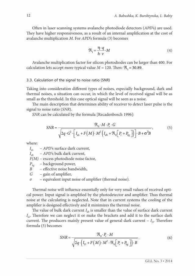
Often in laser scanning systems avalanche photodiode detectors (APD’s) are used. They have higher responsiveness, as a result of an internal amplification at the cost of avalanche multiplication M. For APD’s formula (3) becomes
ℜ ⋅
⋅⋅1=
qh v
Mh (4)
Avalanche multiplication factor for silicon photodiodes can be larger than 400. For calculation lets accept more typical value М = 120. Then: ℜ1 30 89= . .
3.3. Calculation of the signal to noise ratio (SNR)
Taking into consideration different types of noises, especially background, dark and thermal noises, a situation can occur, in which the level of received signal will be as small as the threshold. In this case optical signal will be seen as a noise.
The main description that determines ability of receiver to detect laser pulse is the signal to noise ratio (SNR).
SNR can be calculated by the formula [Recadenbosch 1996]:
SNR=M P G
q G I +F M M I + P +P B+
r
ds db r bg
ℜ ⋅ ⋅ ⋅
⋅ ⋅ ( ) ⋅ ℜ ( )
⋅
0
2 202 s 22B
, (5)
where: Ids – APD’s surface dark current, Idb – APD’s bulk dark current, F(M) – excess photodiode noise factor, Pbg – background power, B – effective noise bandwidth, G – gain of amplifier, σ – equivalent input noise of amplifier (thermal noise).
Thermal noise will influence essentially only for very small values of received opti-cal power. Input signal is amplified by the photodetector and amplifier. Thus thermal noise at the calculating is neglected. Note that in current systems the cooling of the amplifier is designed effectively and it minimizes the thermal noise.
The value of bulk dark current Idb is smaller than the value of surface dark current Ids. Therefore we can neglect it or make the brackets and add it to the surface dark current. The producers mainly present value of general dark current – ID. Therefore formula (5) becomes
SNR=P M
q I +F M M P +P Br
D r bg
ℜ ⋅ ⋅
⋅ ( ) ⋅ ⋅ℜ ( ) ⋅0
202
. (6)
THE CALCULATION OF RECEIVED OPTICAL POWER... 13
Geomatics, Landmanagement and Landscape No. 3 • 2014
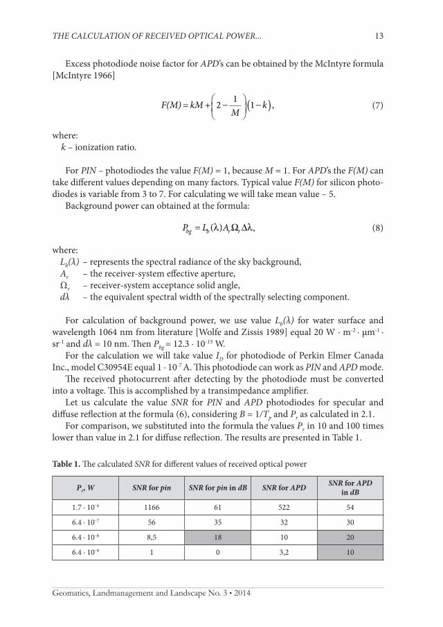
Excess photodiode noise factor for APD’s can be obtained by the McIntyre formula [McIntyre 1966]
F(M)= kM+
Mk ,2 1 1−
−( ) (7)
where: k – ionization ratio.
For PIN – photodiodes the value F(M) = 1, because M = 1. For APD’s the F(M) can take different values depending on many factors. Typical value F(M) for silicon photo-diodes is variable from 3 to 7. For calculating we will take mean value – 5.
Background power can obtained at the formula:
P = L Abg b r r( )l lW D , (8)
where: Lb(λ) – represents the spectral radiance of the sky background, Ar – the receiver-system effective aperture, Ωr – receiver-system acceptance solid angle, dλ – the equivalent spectral width of the spectrally selecting component.
For calculation of background power, we use value Lb(λ) for water surface and wavelength 1064 nm from literature [Wolfe and Zissis 1989] equal 20 W · m-2 · μm-1 · sr-1 and dλ = 10 nm. Then Pbg = 12.3 · 10-15 W.
For the calculation we will take value ID for photodiode of Perkin Elmer Canada Inc., model C30954E equal 1 · 10-7 А. This photodiode can work as PIN and APD mode.
The received photocurrent after detecting by the photodiode must be converted into a voltage. This is accomplished by a transimpedance amplifier.
Let us calculate the value SNR for PIN and APD photodiodes for specular and diffuse reflection at the formula (6), considering B = 1/Тp and Pr as calculated in 2.1.
For comparison, we substituted into the formula the values Pr in 10 and 100 times lower than value in 2.1 for diffuse reflection. The results are presented in Table 1.
Table 1. The calculated SNR for different values of received optical power
Pr, W SNR for pin SNR for pin in dB SNR for APD SNR for APD in dB
1.7 · 10‒4 1166 61 522 54
6.4 · 10‒7 56 35 32 30
6.4 · 10‒8 8,5 18 10 20
6.4 · 10‒9 1 0 3,2 10

A. Babushka, K. Burshtynska, L. Babiy14
GLL No. 3 • 2014
As we see, when sufficient level of received optical power the PIN – photodiodes allow to get higher SNR. APD’s are more acceptable for very small values of received optical power.
Considering SNR the ranging standard deviation σR for pulses with perfect rectan-gular shape with width Тp can be obtained in the formula [Shan and Toth 2008]:
sR p= c
SNRT
2 21⋅ ⋅ , (9)
where: c – speed of light.
Calculated values σR are presented in Table 2.
Table 2. The calculated σR for different values of SNR
SNR σR, cm
1166 3.1
522 4.6
56 14.1
32 18.7
10 33.3
8.5 36.3
3.2 59.2
Producers of the equipment declare ranging standard deviation 1–2 cm for ideal conditions. In last years there is a tendency for reduction output optical power of laser. It’s leads for reduction of SNR. Therefore, it is nearly impossible to achieve such accu-racy in real conditions.
4. Conclusions
1. The main losses of signal by scanning water objects are caused by specular reflection of beam from the water surface; absorption of electromagnetic energy near infrared wavelength by water has smaller influence.
2. When considering specular reflection of water objects, the laser scan angle during surveying must be as small as possible.
3. When implementation of laser scanning of water objects it is more expedient to use avalanche photodiode as detector. This can essentially raise informational content of laser scanning data.

THE CALCULATION OF RECEIVED OPTICAL POWER... 15
4. Photodiode dark current does not have essential influence on SNR of a receiver.5. The main factor influenced on SNR of receiver is the level of received optical power,
which in turn depends on the output power of laser and distance to the object.6. In real conditions it is difficult to rich the value of ranging standard deviation de-
clared by producers.
References
Бабушка А.В. 2012. Особливості відбиття лазерного променя від водних об’єктів. Бабушка А. Міжвідомчий науково-технічний збірник “Геодезія, картографія і аерофотознімання”. Випуск 76, Львів: Національний університет “Львівська політехніка”, 66–70.
Brzank A., Heipke C., 2007. Supervised classification of water regions from lidar data in the Wadden Sea using a fuzzy logic concept. Intern. Arch. Photogram. Remote Sens. Spat. Infor. Sciences, Espoo, Finland, XXXVI, 3, 90–95.
Brenner C., Vosselman G., Sithole G. 2006. Presentation at the International Summer School “Digital Recording and 3D Modeling”, Aghios Nikolaos, Crete, Greece.
Keiser G. 1983. Optical fiber communications. McGraw-Hill, Japan.Mclntyre R.J. 1966. Multiplication noise in uniform avalanche diodes. IEEE Trans. Electron
Devices, ED13, 164–168.Recadenbosch F. 1996. Lidar sensing of the atmosphere: receiver design and inversion algo-
rithms for an elastic system. Barcelona, Spaine, November.Shan J., Toth C.K. (eds.) 2008. Topographic laser ranging and scanning. Principles and process-
ing. CRC Press, Taylor & Francis Group, London.Wolfe W., Zissis G.J. 1989. The infrared handbook. The Infrared Information Analysis Center,
Enviromental Research Institut of Michigan, Detroit.
Andriy BabushkaLviv Polytechnic National UniversityDepartment of Photogrammetry and Geoinphormatics79013 Lviv, Bandera Street, 12e-mail: [email protected]
Dr. Khrystyna Burshtynska Lviv Polytechnic National UniversityDepartment of Photogrammetry and GeoinphormaticsUkraine, 79013 Lviv, Bandera Street, 12 e-mail: [email protected]
Lyubov BabiyLviv Polytechnic National UniversityDepartment of Photogrammetry and GeoinphormaticsUkraine, 79013 Lviv, Bandera Street, 12 e-mail: [email protected]