Embed Size (px)
Citation preview

THE CANADA AVIATION MUSEUM EXHIBIT
THE DESIGN, DEVELOPMENT AND TESTING OF THE CANADAIR CL-227 REMOTELY PILOTED VEHICLES
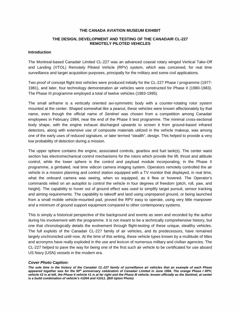
Introduction The Montreal-based Canadair Limited CL-227 was an advanced coaxial rotary winged Vertical Take-Off and Landing (VTOL) Remotely Piloted Vehicle (RPV) system, which was conceived, for real time surveillance and target acquisition purposes, principally for the military and some civil applications. Two proof of concept flight test vehicles were produced initially for the CL-227 Phase I programme (1977-1981), and later, four technology demonstration air vehicles were constructed for Phase II (1980-1983). The Phase III programme employed a total of twelve vehicles (1983-1995). The small airframe is a vertically oriented axi-symmetric body with a counter-rotating rotor system mounted at the center. Shaped somewhat like a peanut, these vehicles were known affectionately by that name, even though the official name of Sentinel was chosen from a competition among Canadair employees in February 1984, near the end of the Phase II test programme. The minimal cross-sectional body shape, with the engine exhaust discharged upwards to screen it from ground-based infrared detectors, along with extensive use of composite materials utilized in the vehicle makeup, was among one of the early uses of reduced signature, or later termed “stealth”, design. This helped to provide a very low probability of detection during a mission. The upper sphere contains the engine, associated controls, gearbox and fuel tank(s). The center waist section has electromechanical control mechanisms for the rotors which provide the lift, thrust and attitude control, while the lower sphere is the control and payload module incorporating, in the Phase II programme, a gimbaled, real time vidicon camera imaging system. Operators remotely controlled the air vehicle in a mission planning and control station equipped with a TV monitor that displayed, in real time, what the onboard camera was seeing, when so equipped, as it flew or hovered. The Operator’s commands relied on an autopilot to control the vehicle in four degrees of freedom (pitch, roll, yaw, and height). The capability to hover out of ground effect was used to simplify target pursuit, sensor tracking and aiming requirements. The capability to takeoff and land using unprepared ground, or being launched from a small mobile vehicle-mounted pad, proved the RPV easy to operate, using very little manpower and a minimum of ground support equipment compared to other contemporary systems. This is simply a historical perspective of the background and events as seen and recorded by the author during his involvement with the programme. It is not meant to be a technically comprehensive history, but one that chronologically details the evolvement through flight-testing of these unique, stealthy vehicles. The full exploits of the Canadair CL-227 family of air vehicles, and its predecessors, have remained largely unchronicled until now. At the time of this writing, these vehicle types known by a multitude of titles and acronyms have really exploded in the use and lexicon of numerous military and civilian agencies. The CL-227 helped to pave the way for being one of the first such air vehicle to be certificated for use aboard US Navy (USN) vessels in the modern era. Cover Photo Caption: The sole time in the history of the Canadair CL-227 family of surveillance air vehicles that an example of each Phase appeared together was for the 50th anniversary celebration of Canadair Limited in June 1994. The orange Phase I RPV, vehicle #2 is at left, the Phase II vehicle #1 is at far right and the Phase III vehicle, known officially as the Sentinel, at center is a build combination of vehicle’s #1004 and #1011. (Bill Upton Photo)

Genesis of Canadair’s CL-227 VTOL RPV Programme Throughout the history of the CL-227 programme, the nomenclature regarding the vehicle description changed in keeping with mission alterations (or even due to ‘political correctness’) in the field of these vehicle types. Most of these terms were used interchangeably with a large overlap before the subsequent adaptation was finally adopted for common use. For the purposes of this chronicle the following descriptions and abbreviations shall be used, as was the convention of these particular times: Remotely Piloted Vehicle (RPV) - Remotely Piloted Helicopter (RPH) - Unmanned or Uninhabited Air Vehicle (UAV) - Unmanned Aerial System (UAS), “…a rose by any other name…” Canadair’s Missiles & Systems Division
In 1947, a small group of Canadian scientists and engineers began studies towards the research and development of a Canadian guided missile programme. By 1950, the advent of a Defence Research Board (DRB) and Canadian Armament Research and Development Establishment (CARDE) project initially called the N-44 Ace Card, later known as the Velvet Glove, air-to-air guided missile programme for the Royal Canadian Air Force (RCAF) was taking shape. The Velvet Glove was a conventional, solid rocket motor propelled air-to-air missile, equipped with a semi-active radar homing device. Starting in August 1951, Canadair’s Special Weapons
Division, under the design authority of the CARDE at Valcartier, Quebec, became heavily engaged in the field of guided missile research and development. CARDE assigned Canadair as the prime contractor to build and test the Velvet Glove missile airframes, ancillary equipment, as well as the associated launch pylons for a Canadair-built RCAF F-86 Sabre Mk 2 and Avro Canada CF-100 Canuck test aircraft for the air launch phase of the test programme. Canadair designated this new project with their model number CL-20 and assigned John Kerr responsibility for the advanced design work. Westinghouse Electric was assigned as the prime electronics sub-contractor. Soon after, the Missiles & Systems Division was formed, an autonomous division of Canadair Limited that was to explore sophisticated technologies beyond the area of manned aircraft. Recruitment of highly skilled scientific and engineering personnel worldwide, specialized in missile and components miniaturization development, was undertaken in order to create a Canadian industrial capability in this particular field. Within a short period of time Canadair had established the only fully equipped guided missile fabrication and advanced test facility in Canada.
The CL-20 Velvet Glove missile mockup on its launch pylon beneath the wing of a Sabre in 1955. The Sabre could carry only one missile under each wing while the CF-100 was capable of carrying either four under the nacelles or two under each wing.
One of the CL-54 Sparrow II missiles undergoes telemetry tests at Canadair’s Plant 4 facility. A series of specially modified CF-100s, designated as the CF-100 Mk 5M were used for the firing trials of the Sparrow II missiles up to 1960.

Rapid technical advancements in aviation and missile technology during the 1950s eventually led to the demise of the CL-20 Velvet Glove system in December 1956. However, new studies commenced in 1955 and, by 1957, work was soon started on the CL-54 Sparrow II model. Canadair Limited was the coordinating contractor for this Douglas-designed supersonic air-to-air missile, destined for initial use with the Douglas F5D-1 Skylancer fighter for the USN and as the main weapon system for the Avro Canada CF-105 Arrow interceptor for the RCAF. Unfortunately, this programme was terminated with the cancellation of both the Skylancer and then the Arrow, leading to some uncertainty as to the future of this Division. Fortunately, perseverance paid off as Canadair proposed and participated in a few more projects that helped to retain the engineering personnel and advanced unmanned technology data base towards developing new missiles, targets and drone systems. A few of these are detailed briefly below: CL-36 Target Drone
A 1953 proposal for a high performance ramjet powered target drone for the RCAF capable of being ground launched, or in a 1954 idea, air launched from a CF-100 aircraft, was designed to serve as a target for fighter gunnery practice and for surface-based anti-aircraft weapons firing. The latter design was for a remotely controlled and more powerful target model to use against the Velvet Glove missile. This was the first Canadair study of a drone system and marked the beginning of long-
enduring and successful work on various unmanned flying vehicles other than missiles. Based on this drone, the later CL-89 was studied early on as a similar, but autonomous version of a target drone. CL-65 Air Launched Towed Target
This 1957 initial study proposal was for a launch and recoverable fiberglass towed target system capable of being installed under the wing of RCAF T-33 Mk 3 or Sabre Mk 6 aircraft for air-to-air testing of the Sparrow II and other missile evaluation programmes. Although designated as a towed target, it was designed to be capable of effecting a pre-determined maneuver if released from the towline. The project was not accepted, with the RCAF deciding to employ Firebee drones obtained from the United States. Later, Delmar towed targets,
bearing a striking similarity to the CL-65 design, were used by the RCAF T-33s until modern times. CL-85 Robot Dispatch Carrier
In 1959, a small, short-range ballistic missile was designed to requirements by the Canadian Army as the Robot Dispatch Carrier. Proposed to be transported via a standard ¾ ton military truck, it had a tandem booster that fired for just 2.25 seconds to impart sufficient velocity to the vehicle to enable it to home onto a radar beacon in a designated landing zone. Pinpoint landing was to be accomplished by a combination of a recovery parachute to slow the descent and stabilize the vehicle along
with a long, crushable ground-penetration nose spike, thus delivering the much needed supplies to the awaiting troops. Another similar, but larger delivery design, the CL-87 Army Logistic Missile System was a controllable airdropped container for the re-supply of an emergency force in a localized conflict.

The relative success of the early missile projects and some subsequent contracts (CL-79 BOMARC components – wings, ailerons and valves, and the Black Brant II sounding rocket programme, based on the usage of existing and surplus Sparrow II components) certainly enriched the knowledge in unmanned systems. Yet similar success eluded Canadair in the research and development field of drones. The later Surveillance Systems Division of Canadair was a direct descendent of the Missiles & Systems Division, and evolved around 1959 / 1960 as Canadair was attempting to salvage much of the talented engineering personnel and technological skills it had amassed for the Velvet Glove and Sparrow II missile programmes. One of the British engineers, John Kerr, formerly responsible for the design work on the Velvet Glove missile also aided in the design proposal for the CL-36 series of target drones as well as preparing the design drawings for the CL-65 towed target. Much later, after joining the newly formed surveillance group when Missiles & Systems was dissolved, and using his unmanned vehicle experience gleaned while with that Division, he had a vision. Kerr brought it to life with inspiration from the CL-36 fuselage design and that soon proved instrumental towards the initial concept design and development of the successful CL-89 Unmanned Surveillance Drone system. CL-89 Unmanned Surveillance Drone
The CL-89, germinated following the termination of the Sparrow II guided missile programme, was first formally proposed as a Canadair, DDP and US Army sponsored project in May 1960, initially designated as the Short Range Target Acquisition and Surveillance system. Canadair had first recognized a potential market in the field of airborne surveillance systems in November 1958, and by December 1959, the initial studies and preliminary drawing concepts were started as a private venture. With limited funding available, the design work began in earnest during September 1960 and numerous presentations were made in the ensuing
years for support and development contracts. Finally, in November 1963, the Canadian Defence Minister formally announced the purchase from Britain of three Oberon-class submarines, and in exchange, Britain agreed (in June) to invest in a co-operative design, development, test and evaluation partnership in the CL-89 battlefield surveillance drone with Canadair and the US Army. The air vehicle was a small jet-propelled missile-like drone, which was launched with the help of a solid propellant rocket booster from a special pallet on a standard 2½ ton Army truck. At the end of the short boost phase, the rocket assembly falls away and the CL-89 proceeds on a course determined by a pre-set onboard electro-mechanical programmer. Designed to carry photographic or infrared optical sensor packages the first of the prototype drones made its maiden flight from the Yuma Proving Grounds in Arizona on 25 March 1964. In 1965, Germany joined the programme followed by the Italian army in 1974, and by 1979, France became the fourth and last customer. More than 500 CL-89 drones were produced, becoming the first unmanned surveillance system to enter service with the North Atlantic Treaty Organization (NATO), thus assigned the NATO designation AN/USD-501. The only CL-89 trial by fire came when the British Army deployed their CL-89, named Midge, system on more than a dozen successful operational missions for coalition forces during the 1991 Iraqi Gulf War. Shortly thereafter they were retired from service. In 1969, John Kerr was presented with the Canadair Engineering Achievement Award for his contribution to the concept, design and development of the CL-89 surveillance drone system.

The Servotec Periscopter
The origins of the CL-227 can be traced back to 1964 when John Kerr, then Section Chief of the advanced design group, Canadair’s Missiles & Systems Division, was invited to critique the Servotec Periscopter. This British battlefield surveillance project, dating back to 1959, also involved the military division of Canadian Westinghouse and the CARDE as the major subcontractors. Servotec, teamed with C. F. Taylor Metal Works, had also designed and built the pitch control, contra-rotating tail rotor system, for the Canadair CL-84 tilt-wing V/STOL aircraft. This particular contra-rotating system was itself derived from a small British helicopter known as the Rotorcraft Grasshopper. The Canadian Army had purchased some Nord Aviation Entac wire-guided anti-tank missiles and CARDE was
considering enhanced longer-range versions of these. In order to utilize the longer range more effectively, some practical means of extending their visual range tracking was required. Servotec performed some initial design studies, and soon was born the concept for a tethered flying vehicle to carry a low-light video sensor system or a radar platform up to an altitude of 2,438m (8,000ft). The Periscopter design was strictly for a small 1.02m (3.3ft) tall tethered flying platform powered by two 6-hp electric motors driving 1.83m (6.0ft) diameter contra-rotating rotors. The small size was determined to be the best application of a ‘see, but not be seen’ doctrine. It was proposed that it was to be launched from, and recovered to, a form fitting “basket” type arrangement, capable of being deployed from a land or sea (ship) based site. Another proposal for the land-based system had a variant of the Periscopter bottom tethered or mounted to an extendable fixed mast on a military Armored Personnel Carrier (APC).
Servotec testing had progressed to the point where initial static ground tests of the Periscopter on their mobile test rig (a ‘teeter-board’ arrangement) at Cranfield, England, had been performed. Following a full review of the Periscopter system, Canadair did not believe that the vehicle should be tethered and recommended a free-to-roam type of flying vehicle. Powered by an internal gas combustion engine, the free flying vehicle would better suit the system’s intended role, which was to provide clandestine over the horizon intelligence for the Army Brigade Commander. It was also suggested that the technology utilized in the early design of the CL-84 tail rotor system would be an aid towards improving vehicle control.
A version of the Periscopter tethered platform partial cutaway general arrangement. The lower tapered section was shaped to house a radar array. (Modified drawing by Bill Upton)
The typical launch/recovery basket, with integrated electric winch motor and cable drum system, was to be deployed at the end of an extended boom. This boom could be rotated axially and laterally to maintain a level platform relative to the heaving motions of the ship or the undulations of the terrain when land deployed. Following the recovery of the Periscopter to the basket, the assembly could be retracted along rails to a suitable area to enable maintenance duties to be performed.

The Canadair Dynacopter
CARDE and Westinghouse subsequently dropped the Periscopter idea, however, Westinghouse Canada continued with the design and development of a stabilized airborne camera system that eventually culminated with the production of the famed WESCAM system. John Kerr and a small Canadair design team, which included members of the Canadair CL-89 recoverable surveillance drone programme, continued with in-house design studies that eventually led to the new Dynacopter VTOL short-range battlefield surveillance concept. The Dynacopter system design phase lasted from 1965 to 1967 supported partly by Canadair Research and
Development (R&D) funding and partly by funds provided by the government of the United Kingdom. Around the same time, Canadair’s sister company, Convair, was developing an experimental, unmanned VTOL vehicle concept for the US Army and possible US Navy anti-submarine warfare applications, called the Low Altitude Observation or LALO system. This craft, proposed for target designation using a small TV camera, embodied a large, downward directed ducted-fan, annular wing configuration. It was to have a designed range of 40km (25mi), and was to be capable of flying up to a height of 3,048m (10,000ft).
Initially, the early Dynacopter concept possessed many of the characteristics of the proposed Periscopter system, but had much greater flexibility primarily because it was to be flown untethered. The concept was based on a very small rotary winged lifting platform equipped with stabilized real time sensors and data transmitter, to meet the surveillance needs of the Brigade or battle group. It was to have the capability to cover a frontage of 19km (11.8mi) to a penetration depth into enemy territory of about 13km (8.08mi). The 1965 conceptual outline of the compact lifting platform comprised a 1.37m (4.5ft) diameter, contra-rotating open rotor system driven, through a speed reducer and differential gear box, by a 12-horsepower rotary combustion engine. Preliminary discussions were held with Williams Research on the feasibility of using a small gas turbine and with Curtiss Wright for their 60 to 100-horsepower rotary combustion engine then in use as a military Auxiliary Power Unit (APU). It was determined that the smaller horsepower rated rotary engine with less weight would satisfy the criteria for this application.
Early Dynacopter, circa 1965, general arrangement layout. (Modified drawing by Bill Upton)

Attached to the speed reducer box were the fuel tank, electrical generator and an electronics package containing control and data link equipment. Suspended below the speed reducer box, by means of vibration isolators, was the payload housing containing the sensor and stabilized platform. Proposed sensors included an Infrared Linescan (IRLS), vidicon-type recording camera or an electronic intelligence (ELINT) system. A data link transmitter/receiver was to be employed to receive command data from the ground and to transmit the sensor and platform data. Standing approximately 0.9m (3.0ft) high and weighing in at 40.82kg (90lb), it had a projected flight endurance of one hour. The complete Dynacopter system was intended to be carried in and operated from a single M113 APC or equivalent sized Army vehicle, by a crew of up to three men. The small size and low weight of the little air vehicle was such that it could be handled easily by only one person.
In these early artists’ impressions, the Dynacopter is seen on the approach for a vertical landing near the Army APC in a cleared area. Then, retrieval of the diminutive Dynacopter back to the waiting APC was to be accomplished manually. Launching of the Dynacopter was to be mechanized from the roof of the M113 vehicle, or alternatively, from the ground at a point some 18m to 46m (60ft to 150ft) away. The mission was to be flown from the tracking and sensor display stations within the APC, with the yaw platform position maintained with respect to the line of sight to the tracker. Recovery to the ground was to be effected by visual command from the controller observing the platform from the APC gunner’s hatch. Post landing, a crewman would then simply carry the vehicle to the refueling station and prepare it for another mission as necessary. Further detailed studies of the basic design and operational concept of this Dynacopter RPV system eventually led to a complete change in the vehicle layout by 1967. The Canadair CL-227 Dynacopter
In May 1967, a completely new redesign of the vehicle, conceived as the Short Range Real Time Surveillance System (SRRTS), was still referred to as the Dynacopter, but now incorporated the official Canadair Model number prefix, CL-227. The proposed operational aspects of this unmanned light observation platform were governed by US Army requirements for reconnaissance, surveillance and target acquisition functions, to supplement existing data collection means in the 0-15km (0-9.4mi) region beyond the forward edge of the battle area.
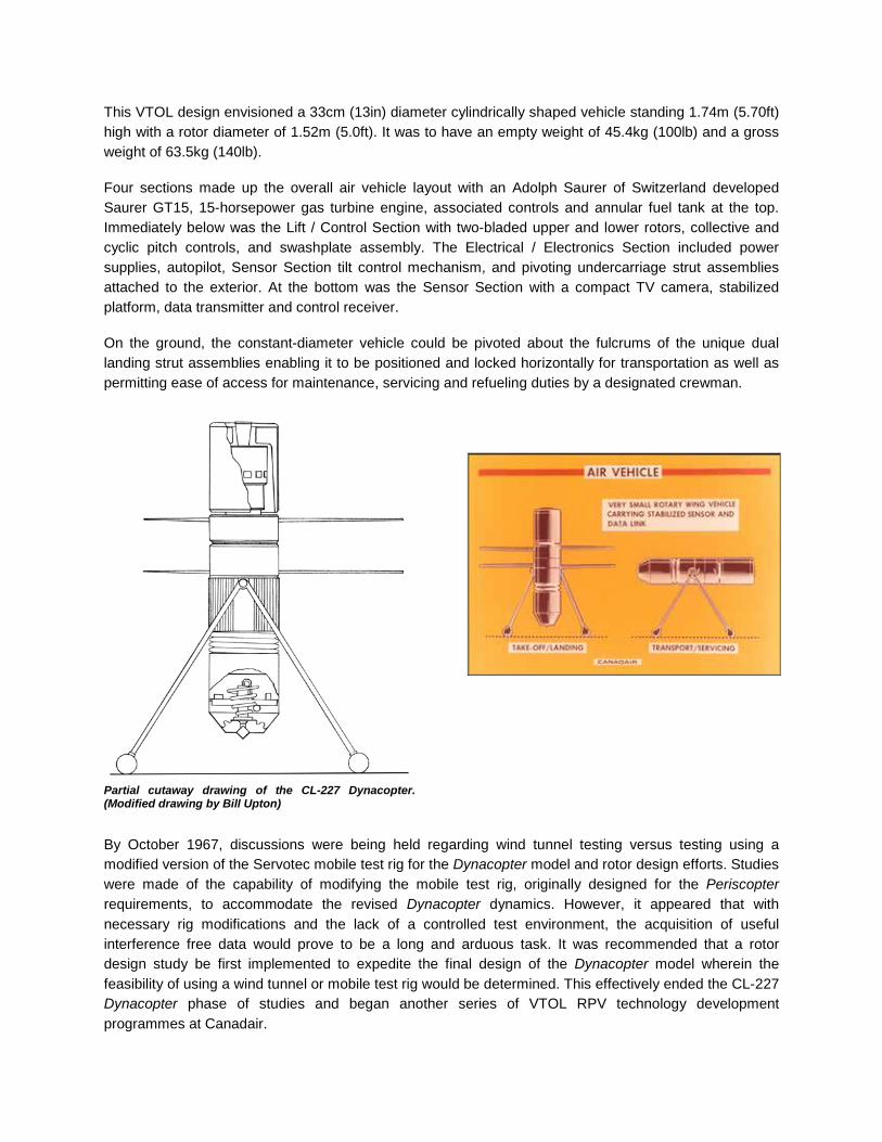
This VTOL design envisioned a 33cm (13in) diameter cylindrically shaped vehicle standing 1.74m (5.70ft) high with a rotor diameter of 1.52m (5.0ft). It was to have an empty weight of 45.4kg (100lb) and a gross weight of 63.5kg (140lb). Four sections made up the overall air vehicle layout with an Adolph Saurer of Switzerland developed Saurer GT15, 15-horsepower gas turbine engine, associated controls and annular fuel tank at the top. Immediately below was the Lift / Control Section with two-bladed upper and lower rotors, collective and cyclic pitch controls, and swashplate assembly. The Electrical / Electronics Section included power supplies, autopilot, Sensor Section tilt control mechanism, and pivoting undercarriage strut assemblies attached to the exterior. At the bottom was the Sensor Section with a compact TV camera, stabilized platform, data transmitter and control receiver. On the ground, the constant-diameter vehicle could be pivoted about the fulcrums of the unique dual landing strut assemblies enabling it to be positioned and locked horizontally for transportation as well as permitting ease of access for maintenance, servicing and refueling duties by a designated crewman.
Partial cutaway drawing of the CL-227 Dynacopter. (Modified drawing by Bill Upton)
By October 1967, discussions were being held regarding wind tunnel testing versus testing using a modified version of the Servotec mobile test rig for the Dynacopter model and rotor design efforts. Studies were made of the capability of modifying the mobile test rig, originally designed for the Periscopter requirements, to accommodate the revised Dynacopter dynamics. However, it appeared that with necessary rig modifications and the lack of a controlled test environment, the acquisition of useful interference free data would prove to be a long and arduous task. It was recommended that a rotor design study be first implemented to expedite the final design of the Dynacopter model wherein the feasibility of using a wind tunnel or mobile test rig would be determined. This effectively ended the CL-227 Dynacopter phase of studies and began another series of VTOL RPV technology development programmes at Canadair.
Aerodynamic Studies and Technology Development Programmes Canadair CL-240, CL-253 and CL-265
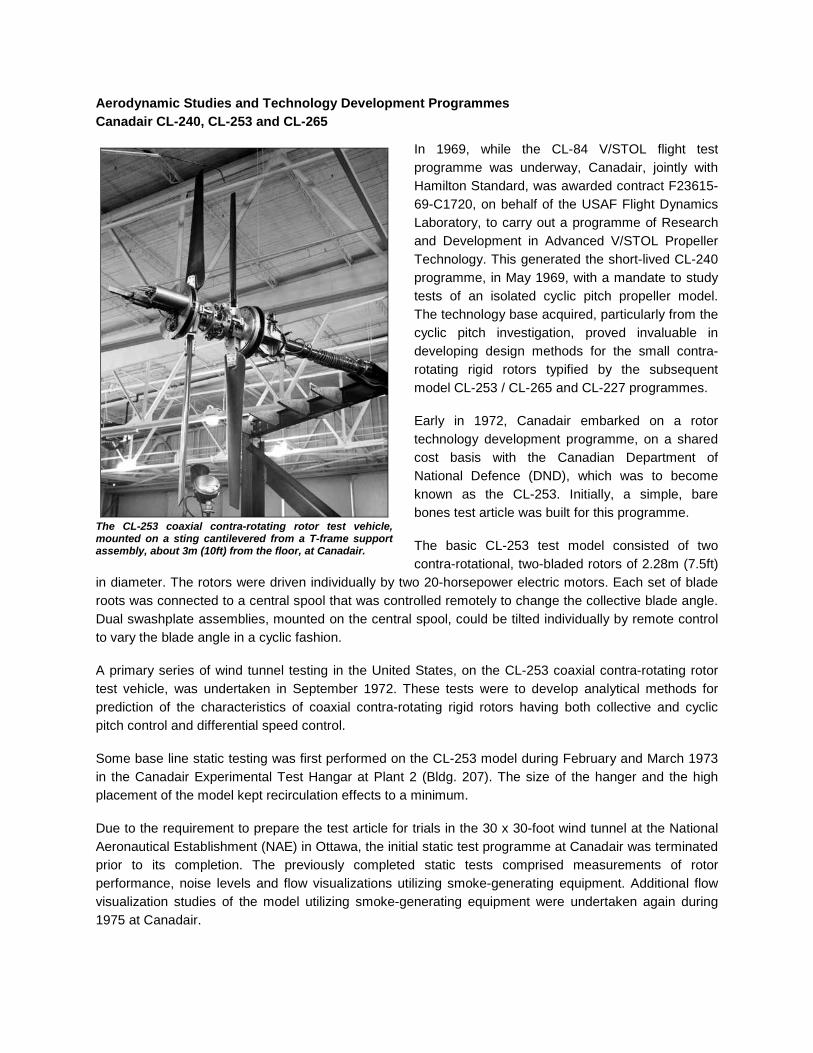
In 1969, while the CL-84 V/STOL flight test programme was underway, Canadair, jointly with Hamilton Standard, was awarded contract F23615-69-C1720, on behalf of the USAF Flight Dynamics Laboratory, to carry out a programme of Research and Development in Advanced V/STOL Propeller Technology. This generated the short-lived CL-240 programme, in May 1969, with a mandate to study tests of an isolated cyclic pitch propeller model. The technology base acquired, particularly from the cyclic pitch investigation, proved invaluable in developing design methods for the small contra-rotating rigid rotors typified by the subsequent model CL-253 / CL-265 and CL-227 programmes. Early in 1972, Canadair embarked on a rotor technology development programme, on a shared cost basis with the Canadian Department of National Defence (DND), which was to become known as the CL-253. Initially, a simple, bare bones test article was built for this programme. The basic CL-253 test model consisted of two contra-rotational, two-bladed rotors of 2.28m (7.5ft)
in diameter. The rotors were driven individually by two 20-horsepower electric motors. Each set of blade roots was connected to a central spool that was controlled remotely to change the collective blade angle. Dual swashplate assemblies, mounted on the central spool, could be tilted individually by remote control to vary the blade angle in a cyclic fashion. A primary series of wind tunnel testing in the United States, on the CL-253 coaxial contra-rotating rotor test vehicle, was undertaken in September 1972. These tests were to develop analytical methods for prediction of the characteristics of coaxial contra-rotating rigid rotors having both collective and cyclic pitch control and differential speed control. Some base line static testing was first performed on the CL-253 model during February and March 1973 in the Canadair Experimental Test Hangar at Plant 2 (Bldg. 207). The size of the hanger and the high placement of the model kept recirculation effects to a minimum. Due to the requirement to prepare the test article for trials in the 30 x 30-foot wind tunnel at the National Aeronautical Establishment (NAE) in Ottawa, the initial static test programme at Canadair was terminated prior to its completion. The previously completed static tests comprised measurements of rotor performance, noise levels and flow visualizations utilizing smoke-generating equipment. Additional flow visualization studies of the model utilizing smoke-generating equipment were undertaken again during 1975 at Canadair.
The CL-253 coaxial contra-rotating rotor test vehicle, mounted on a sting cantilevered from a T-frame support assembly, about 3m (10ft) from the floor, at Canadair.
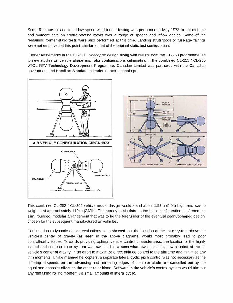
Some 81 hours of additional low-speed wind tunnel testing was performed in May 1973 to obtain force and moment data on contra-rotating rotors over a range of speeds and inflow angles. Some of the remaining former static tests were also performed at this time. Landing struts/pods or fuselage fairings were not employed at this point, similar to that of the original static test configuration. Further refinements in the CL-227 Dynacopter design along with results from the CL-253 programme led to new studies on vehicle shape and rotor configurations culminating in the combined CL-253 / CL-265 VTOL RPV Technology Development Programme. Canadair Limited was partnered with the Canadian government and Hamilton Standard, a leader in rotor technology.
This combined CL-253 / CL-265 vehicle model design would stand about 1.52m (5.0ft) high, and was to weigh in at approximately 110kg (243lb). The aerodynamic data on the basic configuration confirmed the slim, rounded, modular arrangement that was to be the forerunner of the eventual peanut-shaped design, chosen for the subsequent manufactured air vehicles. Continued aerodynamic design evaluations soon showed that the location of the rotor system above the vehicle’s center of gravity (as seen in the above diagrams) would most probably lead to poor controllability issues. Towards providing optimal vehicle control characteristics, the location of the highly loaded and compact rotor system was switched to a somewhat lower position, now situated at the air vehicle’s center of gravity, in an effort to maximize direct attitude control to the airframe and minimize any trim moments. Unlike manned helicopters, a separate lateral cyclic pitch control was not necessary as the differing airspeeds on the advancing and retreating edges of the rotor blade are cancelled out by the equal and opposite effect on the other rotor blade. Software in the vehicle’s control system would trim out any remaining rolling moment via small amounts of lateral cyclic.

The 2-bladed design wind tunnel model setup in the NAE V/STOL wind tunnel, in 1973. Each rotor blade had a flattened shank and was installed into the similarly flattened and slotted upper or lower hub. Six hex-head bolts and locknuts retained each blade. The landing struts and balled feet are remnants from the previous 1967 CL-227 Dynacopter design effort. The test vehicle’s shape had by this time evolved into more of a what some unimaginably called a double “light bulb” configuration. A more apropos and permanent nickname regarding the vehicle’s shape would come later. Mounted horizontally in the NAE’s 30 x 30-foot low speed tunnel in Ottawa, each hub of the wind tunnel model was powered by a 20-horsepower water cooled electric motor driving a two-bladed rotor system incorporating remotely controllable cyclic and collective pitch. Once again, as in the 1967 CL-227 Dynacopter design, the vehicle incorporated the feature of pivoting about the fulcrums of the undercarriage assemblies, located on the upper part of the Control Module, to aid in ground maintenance and servicing accessibility. Having established the performance, stability, and controllability of this initial test design with a high degree of confidence, a series of detailed feasibility studies followed in 1974. These studies assessed mission effectiveness and vulnerability, eventually confirming the worth of the system. A complete strip down, inspection and rebuild of the CL-253 / CL-265 test article for subsequent static and wind tunnel tests was undertaken during the middle months of 1975. Canadair rotor blade manufacturing technology had evolved to the point that, with confidence, new master rotor blades, blade moulds and new blades manufactured with Kevlar material could be undertaken. Vibration characteristics with the two-bladed rotor design quickly proved unacceptable. Backed up with the results obtained from the Research and Development in Advanced V/STOL Propeller Technology Programme undertaken by Canadair, the initial two-bladed rotor design was changed to a three-bladed rigid rotor system. Dynamic tests continued to be performed at Canadair to perfect flight-worthy rotor hardware. Canadair undertook technology development eventually evolving the manufacturing techniques necessary to produce the lightweight glass-fibre rotor blades having very low radar reflectivity.

During this same time frame, a full-scale display model incorporating the two-bladed rotor concept, yet minus any type of landing gear, was made ready by Canadair’s Experimental Department’s model shop and shipped for its premiere in Europe. For display, the model was placed vertically atop a mounting column with a rounded interior. It made appearances at the prestigious Paris Air Salon and Farnborough Air Shows. In 2011, this display model with its four slightly damaged rotor blades was re-discovered in a storage facility and photographed by the author (left).
Horizontally mounted on a stinger that both supported and provided routing for the myriad control and data harnesses, the 3-bladed test vehicle is seen here, in Building 207 during September 1975, undergoing additional flow visualization static testing. Note the white wool tufts arranged on the Data Module. These Kevlar/epoxy laminate rotor blades were successfully developed in-house and were subsequently used on the first CL-227 Phase I RPV air vehicle. These static and wind tunnel tests along with the analytical model of the vehicle helped to quantify the aerodynamic characteristics of the vehicle shape and the contra-rotating rotors for the subsequent model of the CL-227. With all of this information in hand, final development of the ultimate CL-227 flight-test vehicle progressed in three major design and flying hardware phases.

Canadair CL-227 PHASE I – Proof of Concept Vehicles Preliminary development of the CL-227 proof of concept system began in May 1977 with the signing of a $625,000 CDN cost sharing contract for the construction of a Research and Development prototype air vehicle. This first prototype consisted of a mix of components retrieved from the previous CL-265 wind tunnel model along with new build items of equipment. By July 1977, detailed engineering documentation was released to the Experimental Engineering and then on to the Experimental Shops at Plant 2 to begin construction of the first test vehicle for preliminary static and tethered flight-testing. As had been done previously, with great success, for the prototypes of new innovative Canadair designs (CL-41 trainer and CL-84 V/STOL tilt-wing aircraft), the CL-227 would be built in a “Skunk Works” fashion. This entailed using minimal drawings, descriptive memos and word-of-mouth interactions between the small engineering design group and Canadair’s Experimental manufacturing and assembly shops. Phase I testing was to serve two purposes, first to obtain technical test data required to design a readily usable RPV and secondly, and perhaps more importantly, to convince the potential user community that an air vehicle of this configuration could fly and be easily controlled from the ground.
A full-scale three-rotor dark green and light grey painted model, reflecting the planform of the previous, smaller two-rotor design, was displayed at the later Paris and Farnborough Air Shows. Some foreign and domestic interest was generated aimed at meeting the emerging early military requirements for a real time surveillance system. This model, and a similar half-scale version, soon made the rounds of world aviation trade shows and continued to do so in subsequent years. Later, this green and grey painted model with three-bladed rotors was powered by a small electric motor and was used as a dynamic prop for various PR and Marketing purposes.
Some of the potential applications that were originally envisioned for this new model of the CL-227 Short Range Real Time Surveillance System RPV included land and varied sea-based variants: Land Forces Variant · Operational capabilities from unprepared
field sites with a minimum risk of detection · Surveillance and target acquisition · Fire adjustment and target designation · Command and control of own forces · Jamming of enemy radar · Communications relay station · Electronic listening (ELINT) station · Electronic warfare · Radiation monitoring · Gathering meteorological data
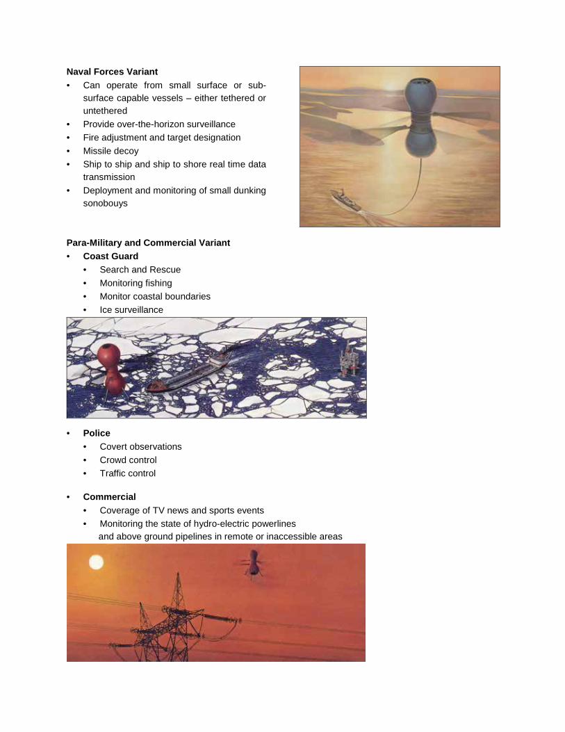
Naval Forces Variant · Can operate from small surface or sub-
surface capable vessels – either tethered or untethered
· Provide over-the-horizon surveillance · Fire adjustment and target designation · Missile decoy · Ship to ship and ship to shore real time data
transmission · Deployment and monitoring of small dunking
sonobouys
Para-Military and Commercial Variant · Coast Guard
· Search and Rescue · Monitoring fishing · Monitor coastal boundaries · Ice surveillance
· Police
· Covert observations · Crowd control · Traffic control
· Commercial · Coverage of TV news and sports events · Monitoring the state of hydro-electric powerlines and above ground pipelines in remote or inaccessible areas

The Phase 1 RPV was designed originally to incorporate the Saurer GT15 gas turbine power plant, or alternatively, an Eaton 120-D gas turbine. However, due to the unavailability of these engines at the time, a 20-horsepower Sachs Wankel rotary combustion engine, readily available from a local distributor, was substituted. This proven reliable engine drove both 3-bladed contra-rotating rotor hubs via a centrifugal clutch, differential gearbox and through a central quill shaft. The upper set of rotors rotated counter-clockwise and the lower set clockwise when viewed from above, with the rotor blade collective pitch controlled via the swashplate and an actuator mechanism located at the vehicle’s center of gravity. The modular layout of the vehicle, consisting of, at the top, the Power Module, centrally the Propeller Module, then the Control Module, permitted simple and quick interchangeability to suit mission or maintenance requirements. The exterior was completely covered with removable low radar reflectivity composite skins. It was this assembled modular layout scheme that eventually contributed to the very informal, but very long-lasting, naming of the vehicle as the “Peanut” by the design group, a name that stuck with the project throughout all variants of the type for years. No other name would do, obviously.
Canadair design engineer extraordinaire, John Kerr and the Canadair CL-227 Phase I modular concept layout.
At left is the Power Module with the top of the Wankel rotary engine visible, circular screened carburetor intake foremost, gasoline/oil fuel filler port on the right with the custom handmade muffler and exhaust behind. Central is the Propeller Module assembly showing the anodized gearbox housing and the circular stainless steel centrifugal clutch housing mounted above the upper differential brake ring. Four Power Module attachment lugs are seen affixed to the exterior of the gearbox housing. The upper and lower rotor hubs protrude from the segmented skins. At right the Control Module and its electronic boxes (designed and built in-house), vertical and directional gyros (borrowed from the CL-89 drone programme) and umbilical connection underneath. Four angled metal landing pegs are affixed to the frame. Later, these pegs would be interchanged with varied landing leg arrangements or horizontal metal landing pegs. Six (3 upper and 3 lower specific) accurately balanced Kevlar rotor blades with metal shanks lie in the foreground. The six rotor blades, designed and manufactured in-house, were made from lightweight Kevlar material with a hard foam core and were each securely installed onto the air vehicle by 5/16-inch diameter blade attachment bolts just prior to a flight test. The blades were removed prior to all transportation efforts.

CL-227 Phase I rotor blade assembly consists of the blade master mold at the top, the two blade mold halves, one set each for the upper and lower rotors, for the lay-up of the Kevlar material. A sample, completed blade with metal shaft attached, is seen at bottom. Each rotor blade was individually weighed, balanced and assigned a specific upper or lower hub number corresponding to a similarly numbered hub on the propeller module of the assigned air vehicle. Individual or complete rotor blade sets were not interchangeable between vehicles. The prototype CL-227 Phase I air vehicle stood 1.4m (4.5ft) high, had a maximum body diameter of 50.8cm (20in), and a rotor diameter of 2.3m (7.6ft). It weighed in at 91kg (200lb). Due to its experimental nature, the complete vehicle was painted up in an overall International Orange scheme for higher visibility. A white ‘X’-in-circle symbol was applied to the exterior of the Control Module’s skin directly facing the RPV operator as a means of visual orientation during flight. In order to perform flight tests of this new air vehicle in relative safety and to minimize the risk of losing the test article during tests, a new facility, familiarly dubbed “The Tether Site”, was constructed near a Compass Rose of the former airport. This was situated behind Canadair’s Plant 1 complex from 1977. A mobile Take-Off And Landing Station (TOALS) was built and installed on the back of a modified 2 ½ ton Canadian Armed Forces (CAF) truck- commonly called a “deuce-and-a-half”. Similar in concept to that proposed for the earlier Periscopter project, the TOALS consisted of an extendable tubular frame assembly on the truck bed incorporating centrally a winch and tether cable/electrical harness spool assembly. At the outer extremity, structure that would accept a variety of takeoff and landing platforms. A flight test tower consisting of a 9.2m (30ft) high modified aircraft servicing stand incorporating a small diameter steel cable routed through pulleys and attached to the top and bottom of the CL-227 vehicle forming a continuous loop tether system was constructed. This was located immediately adjacent to a 7.3m (24ft) high octagonal fenced safety cage that served to enclose and protect the test area, support vehicles and authorized personnel in the vicinity.
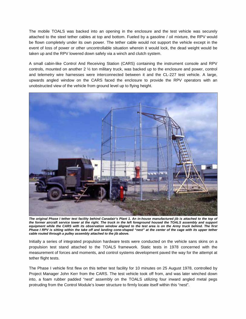
The mobile TOALS was backed into an opening in the enclosure and the test vehicle was securely attached to the steel tether cables at top and bottom. Fueled by a gasoline / oil mixture, the RPV would be flown completely under its own power. The tether cable would not support the vehicle except in the event of loss of power or other uncontrollable situation wherein it would lock, the dead weight would be taken up and the RPV lowered down safely via a winch and clutch system. A small cabin-like Control And Receiving Station (CARS) containing the instrument console and RPV controls, mounted on another 2 ½ ton military truck, was backed up to the enclosure and power, control and telemetry wire harnesses were interconnected between it and the CL-227 test vehicle. A large, upwards angled window on the CARS faced the enclosure to provide the RPV operators with an unobstructed view of the vehicle from ground level up to flying height.
The original Phase I tether test facility behind Canadair’s Plant 1. An in-house manufactured jib is attached to the top of the former aircraft service tower at the right. The truck in the left foreground housed the TOALS assembly and support equipment while the CARS with its observation window aligned to the test area is on the Army truck behind. The first Phase I RPV is sitting within the take off and landing cone-shaped “nest” at the center of the cage with its upper tether cable routed through a pulley assembly attached to the jib above. Initially a series of integrated propulsion hardware tests were conducted on the vehicle sans skins on a propulsion test stand attached to the TOALS framework. Static tests in 1978 concerned with the measurement of forces and moments, and control systems development paved the way for the attempt at tether flight tests. The Phase I vehicle first flew on this tether test facility for 10 minutes on 25 August 1978, controlled by Project Manager John Kerr from the CARS. The test vehicle took off from, and was later winched down into, a foam rubber padded “nest” assembly on the TOALS utilizing four inward angled metal pegs protruding from the Control Module’s lower structure to firmly locate itself within this “nest”.

These first tether test flights were promising and strong marketing efforts to promote debut of this little vehicle resulted in interest being expressed by the Swedish Armed Forces and the United States Marine Corps (USMC) to witness demonstration flights. Demonstrations for visitors were conducted successfully with the air vehicle painted an overall light gull grey, and using a flat, large diameter ground effect platform on which to take off and land. Discussions were also held with representatives of the US Army Air Research and Development Command (ARDC) towards possible collaboration on the programme. By October 1978, some 40 hours of static testing and 200 tether flight tests had been completed meeting the initial programme objectives within the approved budget and schedule.
The first tethered flight of the Canadair CL-227 Phase I RPV. The CARS, with the RPV operators peering through the window, is in the right background. The Canadair CL-227 branding on the vehicle would soon be removed, never to reappear in this Phase.
RPV #1 in the original tether test facility, inflight, during a formal demonstration on 16 November 1978. Note that four wooden feet have replaced the original landing pegs in order to effect landing on the flat ground effect platform visible at the bottom of the photo.
In 1978, the first CL-227 Project Team included L-R, front row, Richard Théberge, Ernie Semple, John Kerr, Ron Eberts, Andy Auld and Fred Horst. Above, on the TOALS truck alongside the first RPV are Marius Huvers and Peter Ghey. By the end of the year Théberge, Eberts and Auld had left, making the small group somewhat smaller. On 4 February 1979, Bill Upton joined the small CL-227 group as a mechanical design/draftsman under the tutelage of Peter Ghey.

In this subsequent tether flight demonstration of the grey-painted vehicle on 2 November 1978, a removable metal tubular ring was attached at the bottom of the wooden pads of RPV #1. The Department of Industry Trade and Commerce provided funding for further technology development which enabled a second air vehicle, incorporating design and weight reduction changes, to be constructed in 1979 to supplement the flight test and demonstration programme. One redesign change was to the coning angle of the rotors, changed from 4 degrees on the first vehicle to 0 degrees on the second. A new set of grey painted rotor blades was made for RPV #2. To visually differentiate this vehicle from RPV #1, a white ‘+’ in-circle symbol was applied to the operator facing side of the Control Module’s skin. Improvements to the auto-stabilization systems of both vehicles were also incorporated at this time. To permit comprehensive flight testing of the Peanut a new expanded tether-testing facility, for RPV proving and operator training was designed and built during 1979-1980. Limited vertical and lateral flight excursions to be conducted via a running tether system attached at the top and bottom of the vehicle with quick disconnect couplings was incorporated in the design. This facility included a larger trailer type ground control station incorporating mechanical and electrical work areas. A new 12.2m (40ft) high tubular steel tower with an integrated tether cable winch room and attached TOALS was located alongside. A donut shaped platform, supported on a pair of bearings, was used to seat the RPV for take off and landing. A solenoid-activated lock prevented the platform from rotating during engine start. The lock was disengaged to allow the platform rotational freedom to permit yaw control system verification prior to take off. Four metal struts, protruding radially from the Control Module structure, were used to seat the RPV on the pad. Clamps bolted down over the struts into the platform permitted static test runs to be conducted at all speeds.

A typical tether test flight included attaching a command and data umbilical cable to the vehicle unreeled from a spool within the TOALS. Vertical travel permitted by the tether cable system was limited to approximately 10m (33ft), with a maximum lateral extension of 4.5m (15ft) allowed in any compass direction. A geared clutch on the winch cable drum would be released and the CL-227 would be flown off the pad to perform up to 16 minutes of flying. Landing was accomplished by engaging the geared clutch and manually winching in the lower tether cable against a fixed level of thrust on the vehicle. The first flight from this new tether facility was performed on 20 July 1979 using PRV #1, and by early 1981, the two Phase I test vehicles had logged over 300-tether flights.
This is the RPV control and telemetry setup in the forward half of the new Tether Test facility trailer during the Phase I programme. Closest on the left is the telemetry rack/chart recorder. The floor console controlled and displayed engine functions and other parameters. The RPV Pilot (usually Fred Horst) performed his tasks from the console on the raised platform in front of the large angled window. Vehicle control was split between two operators; the Pilot was primarily responsible for pitch, roll and yaw attitude, collective control and tether cable extension. The Flight Engineer being responsible for electrical and engine starting controls and systems monitoring. The rear half of the trailer contained electrical and mechanical work areas for RPV maintenance and storage between flights.
RPV #1 during a 1979 test flight on the new Tether Test facility with upper tether cable extension allocated to permit limited lateral traversing of the vehicle. This test facility would continue to test variants of the CL-227 until 1994 when it was dismantled for an encroaching housing project.
Since the designers of the air vehicles, the test site and flight test team members were all one and the same, in-depth familiarity by these personnel with all components and systems idiosyncrasies and problems helped to rapidly advance the progress of the RPV flight tests. Including this entire group in all aspects of the project helped to instill high morale and contributed to a successful operational environment for many years. In addition to John Kerr, the full time team members included; Fred Horst - electrical/electronics design and RPV Operator; Ernie Semple - electrical/electronics design and analyst; Peter Ghey – supervisor of mechanical design and flight test; Marius Huvers – electro-mechanical design and analyst; Bill Upton – mechanical design draftsman and flight test; Gunther Goritschnig – engine specialist and RPV Operator. Of course, Kerr’s secretary Denyse Parisien ruled the roost in the office. Some early vehicle control problems demonstrated dramatically, to the consternation of crowds of employees watching on breaks or lunch, the inherent safety and forethought of using a tethered type system of flight-testing. Only one minor vehicle-damaging incident occurred early on and procedures were successfully employed that ensured that no further problems were ever encountered in the following fifteen years of CL-227 tether test flights.

Sufficient stability, controllability and reliability had been demonstrated by the two CL-227 RPV’s to permit a series of free flight tests to take place in 1980. John Kerr insisted that at least ten flawless tether test flights be performed, per air vehicle, prior to committing an RPV to a free flight test. Both of the CL-227 vehicles were modified to incorporate a metal tubular frame, integrated landing ring, in place of the former metal pegs. Each vehicle now stood 1.52m (5.0ft) high. To effect these free flights, the vehicle was removed from the tether facility and placed on a circular rubber-coated plywood sheet anchored in the ground within sight of the control cabin. A 30.5m (100ft) long power, command and data transmission umbilical harness from the control cabin to the vehicle was attached securely. The first free flight took place successfully from the Cartierville Airport/Canadair facilities on 19 March 1980. The CL-227 RPV #2 lifted off, trailing its attached umbilical harness, and was truly in its element. An intensive four-minute flight programme was performed within a 20m (65.6ft) square, flag delineated-boxed area in winds ranging from 20 to 36km/h (12 to 22mph). The little RPV proved easy to control and was completely stable in all axes when translating from point to point and performing short climbs and descents. Landing was accomplished onto a large icy patch of ground and the vehicle’s vibrations caused it to skitter about somewhat like an air hockey puck until the engine was commanded to off. For future free flights, wide strips of black rubber sheet were wrapped securely around the landing ring at four locations to keep the skittering or sliding to a minimum.
Mechanical Design supervisor Peter Ghey installs the rotor blades onto RPV #2 at the icy take-off site preparatory to the first CL-227 free flight. The grey coloured command and data umbilical harness snakes behind him. The white cable bundle provided electrical start power to the engine and was released from the vehicle once full power was achieved.
This first successful free flight of the CL-227 at the Canadair facilities proved that the long thought out idea for such a unique flying surveillance air vehicle was indeed sound. And to silence the uninformed critics, no, that is not a long, solid metal pole supporting the vehicle for photo purposes, it is in fact the flexible main umbilical harness.
In June of 1980, to alleviate anxieties of local residents watching from a nearby shopping center and public road, who were no doubt wondering about the flights of this alien looking craft, the CBC television news programme “City at Six” sent a team of reporters to get a first-hand report on the CL-227. Interviews were conducted with the CL-227’s marketing director and test team members describing the vehicle and its components, with film footage shown of the Peanut in flight. This broadcast seemed to be well received both within and outside the Company, and interest was expressed from potential user organizations.

RPV #2 performed an additional twelve free flights while RPV #1 performed a total of six, the first of which took place on 11 July 1980 before more than 30 representatives of the DND and the Department of Industry, Trade and Commerce. Extensive discussions were held with these representatives on a wide range of issues dealing with potential military and civilian applications for the CL-227. During a typical Phase I free flight mission, multiple take-off and landings were performed, each comprising a flight. In 1980 and 1981, during 12 missions, some 22 free flights were performed, all without incident, during which approximately forty-seven minutes of airtime were logged. All free flights were flown without the engine muffler-side skin attached to permit additional local area cooling. All post-flight inspections would typically reveal unwanted oil leaks, especially those near the rotating differential brake rings where contamination would cause the solenoid activated brake pads to slip, with a resulting loss of yaw control - a definite hazard during free flights. Therefore meticulous degreasing, and if necessary resealing, was required prior to the next flight. The MIL-L-7808 lubricating oil had an annoying tendency to leak through the minuteness of openings in hardware joints, wire bundles, or sealant. Judicious use of PR-1422 sealant at the found point of leak seemed only a stopgap measure as this grade of oil would seemingly seek out an alternate place to leak from and add to the postflight chores. In November 1980, a series of free flight missions provided the opportunity of using a thin Kevlar line attached to the bottom of the vehicle and routed through an in-ground metal loop to permit manual haul-down landings. Three easily controlled haul-down landings were performed successfully by Peter Ghey verifying the feasibility of this potential alternate means of landing the vehicle and justifying its proposed application in the upcoming Phase II and future versions design efforts.
The author visually monitors RPV #2, relaying pertinent observations to the RPV operators (Fred Horst, Marius Huvers, Guenther Goritschnig) during a Phase I free flight demo on 15 May 1981 on the Canadair field. The RPV operators visually observed the east-west translations of the vehicle in flight, while the outside observer watched and reported on the north-south movements within specific orange-flagged boundaries.

RPV #2 is seen in a stable high hover during an earlier free flight. Then, Gilbert Ouellette and the author perform a cursory post-flight inspection checking for leaks and if any rotor hub binding is evident. Gilbert was a remarkably skilled tradesman with the Experimental Shops, having more than 40 years experience at Canadair. He virtually hand built and assembled the mechanical components of each of the diminutive Phase I vehicles. Modifications to the Phase I vehicles were performed by the experienced workers of the Experimental Shops under the supervision of Jean Simard and René Audette. These mods or repairs had to be completed yesterday – oftentimes these diligent workers provided them sooner! The final tether and free flights of the Phase I series both occurred on 25 June 1981 as part of a last minute scheduled quick response set-up, tether test, and free flight demonstration for representatives of the US Marine Corps. All events went off without a hitch. This was a great testament to the test crew who at the time were all involved exclusively in the design, fabrication and assembly of the newer CL-227 Phase II air vehicles and associated support equipment. The two Phase I air vehicles and associated hardware had been basically cocooned and stored up to this point, but fortunately the test team’s expertise prevailed in their flawless preparations and performance of the last of the Phase I RPV flights.
In order to further verify the theoretical aerodynamic characteristics versus actual hardware for validation of the upcoming CL-227 Phase II design concept, RPV #2 was wool tufted, and performed a series of data gathering tether flights on 19 May 1981. These final dynamic airflow measurements aided the new vehicle design team to recontour the shape of the upper and lower modules for the Phase II design drawings.
RPV #2 performs the last flight of the Phase I series in a demonstration for the US Marines. This rarely seen backside of the vehicle reveals the uncovered muffler and engine in the Power Module. That skin section was removed to preclude excessive heat buildup in the Power Module. RPV #1 is on static display within the confines of the Tether Test facility, where modifications were already underway to support the Phase II vehicles.
From 1977 through 1981, the CL-227 Phase I core design engineering, hardware, and software integration and flight test department numbered less than a dozen people. It was seen that this small group of good people could work quickly and efficiently, keeping close control over all aspects of the project. They all diligently carried on with the necessary addition of some new engineering, design and planning personnel towards the upcoming CL-227 Phase II programme design and test efforts.

Some time in 1981, a Canadian Armed Forces (CAF) Captain paid a visit to the CL-227 design office to discuss the possible merits of utilizing the CL-227 RPV on Fast Patrol Boats. This was a harbinger of greater, future prospects for CL-227 shipboard operations. Although nothing came out of the meeting at this time, that Captain also went on to greater, future prospects in another new ocean - space. He was Captain (N) Marc Garneau, Canada’s first astronaut! John Kerr, literally the ‘Father’ of Surveillance Systems at Canadair, retired in 1981 after some 29 years of service. In recognition of his dedicated work he received a Canadair Certificate of Invention for the CL-227, “…in appreciation of the contributions remotely piloted surveillance aircraft made towards the improvement of the technology and competitiveness of the company.” A surplus rotor blade from the RPV #2 manufacturing efforts, painted, and then mounted to a mahogany plaque, was also presented to him on behalf of the small CL-227 design and flight test team to which he had been such an integral part of and always remained close to.
CL-227 PHASE I FREE FLIGHT LOG
DATE MISSION No. FLIGHT No. RPV No. FLIGHT TIME
19 March 1980 1 1 2 4 min. 00 sec. 28 March 1980 2 2A 2 4 min. 30 sec. 2B 2 0 min. 57 sec. 02 April 1980 3 3 2 4 min. 18 sec. 11 July 1980 4 4A 1 3 min. 06 sec. 4B 1 1 min. 08 sec. 09 Sept. 1980 5 5A 1 3 min. 26 sec. 5B 1 0 min. 48 sec. 12 Sept. 1980 6 6A 1 2 min. 29 sec. 6B 1 0 min. 56 sec. 23 Sept. 1980 7 7A 2 2 min. 12 sec. 7B 2 1 min. 29 sec. 24 Sept. 1980 8 8A 2 2 min. 31 sec. 8B 2 1 min. 57 sec. 18 Nov. 1980 9 9A 2 3 min. 32 sec. 9B 2 2 min. 01 sec. 19 Nov. 1980 10 10A 2 1 min. 34 sec. 10B 2 1 min. 30 sec. 10C 2 1 min. 25 sec. 15 May 1981 11 11A 2 unrecorded 11B 2 unrecorded 25 June 1981 12 12 2 unrecorded

Canadair CL-227 PHASE II – Technology Demonstrator Vehicles Design work on the CL-227 Phase II medium range technology demonstration programme began in early 1980, following a proposal, valued at $3.3 million, that had been submitted to the Department of Industry Trade and Commerce. Indications were once again received that the US Army was interested in participating in the Phase II programme. One of the aims of this Phase was to demonstrate surveillance and target acquisition using a real time black and white RCA daylight vidicon camera with zoom lens as a payload. The payload was gyro stabilized in pitch and roll to maintain a vertical sight line irrespective of vehicle tilt. The camera orientation in azimuth would be fixed with respect to the RPV body, and the air vehicle flown in a fixed yaw orientation so as to keep the camera image oriented North up at all times. Images were to be transmitted to the ground control station via a dedicated FM microwave transmitter. A Vega Precision Industries commercial C-band microwave data link system was to be utilized for communicating command, data and tracking information via omnidirectional stub antennae mounted on the bottom of the RPV. This eliminated the need for a trailing umbilical, as had been the case on the Phase I vehicles. Navigation and control systems and software were all developed inhouse. Envisioned applications for this new Phase included attack warning; jamming; ELINT; surveillance and target acquisition operations up to about 50km (31mi) from the Forward Line of Own Troops (FLOT).
Four new larger, aluminum-alloy framed, air vehicles, embodying mostly commercial and inhouse designed components, were produced for the Phase II. Each vehicle measured 1.67m (5.5ft) high, had a maximum body diameter of 63.5cm (25in), with a rotor diameter of 2.5m (8.2ft) set at a 4 degree coning angle. The nominal all-up weight was on the order of 125kg (275lbs). Performance characteristics promised an air speed range of hover to 70 knots (130km/h / 81mph) with a climb rate of 3 m/sec (9.8ft/sec) up to a ceiling of 3,000m (9,843ft) ASL. It was to have an endurance of 2 to 3 hours at 500m (1,640ft) ASL.
These RPVs were each to be powered by a specially assembled 24 kW (32-hp) Williams Research Corporation WR34-15-2 gas turbine engine running on standard diesel fuel. Diesel was chosen as it is readily available and, if need be in a pinch, could be siphoned from the accompanying military support trucks. Commercial compressed air was used to spool up the engine to the point when ignition was initiated. This was the point when the most noise was ever generated by the system. When up to full speed, the sound of the engine easily blended into almost any ambient background noise. Dual carbon fiber engine air intakes faced upwards at the top of the Power Module, and at 90-degrees to these, two stainless steel ducted engine exhausts curved downwards conforming to the exterior shape of the module. The hot exhaust gases would be blended into the cool rotating air generated by the rotors, thereby significantly reducing any heat signature visible from the ground.

(Original drawing by Ray Legault - annotations by Bill Upton)

All of the International Orange painted skins and spinners of the three modules were removable and they, along with the rotor blades, were manufactured with Kevlar composite material using continually growing in-house expertise. Another use for lightweight Kevlar was in the landing ring assembly, supported to the main frame of the Control Module via four shock-absorbing legs, providing the capability of landing on unprepared areas. Initial ground run tests revealed that the shock absorbers actually induced more vibration than they damped out, so all four were permanently locked in place with a bolt through each leg. Larger and similar only in basic shape to the former Phase 1 vehicle, this version of the Peanut was designed to realize the VTOL air vehicle concept in all modes of flight and to prove the ground support system essentials. Low thermal, visual, audible and radar signatures were an important part of the overall design. It was intended to demonstrate the inherent flexibility of the VTOL design which permitted rapid deployment, launch and recovery operations from practically any suitable small surface utilizing minimum ground support equipment. Most other RPV systems required complex launchers and varied forms of recovery systems such as parachutes, cushioning landing bag systems, bulky net recovery vehicles, or relatively large expanses of clear terrain on which to deploy and recover from. A mobile Ground Control Station (GCS), maintenance/transport vehicle, Vega antenna trailer, and a mobile TOALS trailer were also designed and built to support free flight operations away from the Canadair facilities. Two Canadian military “deuce-and-a-half” transport trucks and two cargo trailers were loaned to Canadair, and modified as necessary to support the Phase II test programme. The CL-227 Phase I tether-testing facility was upgraded and refurbished to support this new vehicle’s design characteristics, and once again utilized to permit tether flight tests in relative safety.
The compact design and packaging of the Williams WR-34 turboshaft engine, originally designed for small recreational vehicles, and modified for the Phase II air vehicles, is readily evident in these photos. The down angled exhaust ducts are visible at the top immediately above the combustion section. Centrally located is the screened annular intake. The clamped first stage speed reduction gearbox assembly is directly above the keyed offset driveshaft which mates to the second stage gearbox via the RPV’s centrifugal clutch assembly, seen in an accurate graphics impression added to the photo at far left.

A CL-227 Phase II air vehicle flies on the tether across from Canadair’s Plant 1 facility during a demonstration held on 15 October 1981. Many such flight demos were an ongoing fact of life during the Phase II programme.
Inside the revamped Tether Test trailer can be seen the new two-man RPV control console on the far left and the separate Vega Precision Industries’ Radar Set Controller (RSC) console on the stand at right. The circular takeoff platform is just visible through the large observation window above the RSC.
The first tether flight test of a Phase II vehicle (RPV #1) was performed on 1 September 1981. The first free flight, this time using RPV #2 without the upper and lower spinner skins installed, was performed at the Canadair facilities on 3 December 1981, with the RPV trailing an umbilical harness for transmitting commands and imagery reception until the new Vega data link system became operational. In rapid succession, three additional and successful free flights with RPV #2 were performed for the benefit of various representatives of the aerospace industry, the United States military, and the Canadian Armed Forces (CAF). These successive demos were performed on the 14, 15 and 16 of December 1981, all of these now employing the full capabilities of the Vega data link control system.
The first free flight of the Phase II programme was an engineering check flight, the only one flown without the Propeller Module spinners installed. The white haul-down spool assembly can be seen just to the left of the landing strut.
RPV #2 sits ready to start for the first Phase II public demonstration flight on this cold, snowy and blustery December day in 1981. The white-domed Vega antenna trailer is seen off in the left background in front of the onlookers.
These first free flights were very restricted in their scope due to the proximity of a busy major Montreal airport, so a light 46m (150ft) maximum height length of Kevlar rope connected the air vehicle to the ground to prevent it from “escaping” in case of some malfunction. All of these performance flights were conducted at a height of approximately 10.6m (35ft) over a rectangular-shaped flight perimeter roughly measuring 18.3 x 9.1m (60 x 30ft) delineated in the snow covered field.
Excellent sensor imagery was recorded and station keeping using the imagery was also demonstrated even in spite of a snowstorm and a gusty 15 knot (28km/h / 17mph) wind on one occasion that would have grounded some rotary wing aircraft. Additionally, these flights were to confirm the feasibility of utilizing the CL-227 in an all-up surveillance role during planned follow-on free flight trials at the Defense Research Establishment Suffield (DRES) in Alberta, Canada.
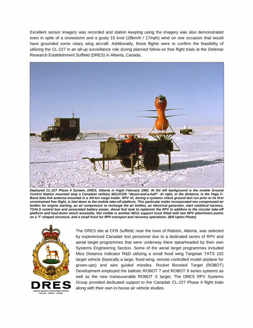
Deployed CL-227 Phase II System, DRES, Alberta in frigid February 1982. At the left background is the mobile Ground Control Station mounted atop a Canadian military M211CDN “deuce-and-a-half”. At right, in the distance, is the Vega C-Band data link antenna mounted in a 3/4-ton cargo trailer. RPV #2, during a systems check ground test run prior to its first unrestrained free flight, is tied down to the mobile take-off platform. This particular trailer incorporated two compressed air bottles for engine starting, an air compressor to recharge the air bottles, an electrical generator, start umbilical harness, TOALS control box and associated battery power, diesel fuel tank to replenish the RPV in addition to the circular take-off platform and haul-down winch assembly. Not visible is another M211 support truck fitted with two RPV attachment points on a ‘T’-shaped structure, and a small hoist for RPV transport and recovery operations. (Bill Upton Photo)
The DRES site at CFB Suffield, near the town of Ralston, Alberta, was selected by experienced Canadair test personnel due to a dedicated series of RPV and aerial target programmes that were underway there spearheaded by their own Systems Engineering Section. Some of the aerial target programmes included Miss Distance Indicator R&D utilizing a small fixed wing Targetair TATS 102 target vehicle (basically a large, fixed-wing, remote controlled model airplane for grown-ups) and wire guided missiles. Rocket Boosted Target (ROBOT) Development employed the ballistic ROBOT 7 and ROBOT 9 series systems as well as the new maneuverable ROBOT X target. The DRES RPV Systems Group provided dedicated support to the Canadair CL-227 Phase II flight trials along with their own in-house air vehicle studies.

A series of short duration tethered flights were conducted at Canadair using the Vega data link, to verify the functionality of the overall system. The Canadair flight-test team, accompanied by a Williams International engine technician, departed for DRES in January 1982, with all mobile ground equipment and three air vehicles in tow. During February and March 1982, 8 free flight tests, ranging in duration from three to twenty minutes, were performed at DRES using RPVs #2 and #3. The first two flights took place on 2 and 4 February using RPV #2. For these two flights only, the vehicle was ground tethered, similar to the previous flights back at Canadair, as a safety precaution due to military air traffic operating in the area. Designed into the Phase II RPV system was the capability of operating the vehicle in either collective pitch control mode, similar to that of a typical helicopter, or in a height control mode. The collective control mode imparted direct command of the rotor blades collective pitch via the RPV operator manipulating the collective pitch lever on the control console in the GCS. This mode of operation was the principal one used during all of the tether and free flight tests and demonstrations conducted previously at the Canadair facilities. The height control mode of operation was based on a Barometric Reference Unit (BARU), a stock item of equipment borrowed from the successful Canadair CL-89 drone programme, which limited the RPV vertical response to selected step height command changes via a control knob on the console. The free flights at DRES provided the first opportunity to practically evaluate the height control system and to measure the RPV performance in vertical and forward flight, as well as during climb and descent.
For these free flight tests the RPV was always launched from the mobile take-off platform using collective control to climb to approximately 100m (328ft) above ground, then maneuvered to a predetermined area of surplus equipment (we called the ‘dump’) some 200m (656ft) downrange from the GCS. Following controllability checks and Go/No Go decisions the changeover to height mode was then initiated and the planned test card was flown. Returning from the mission, the RPV was again oriented above the ‘dump’ and control switched from height mode to collective control, with the landing effected to a flat cleared area in front of the GCS. Contrary to a
multitude of popular press reports and misconceptions over the years, the RPV was never recovered back onto the mobile TOALS trailer, nor was it ever intended to be. Following the mission, recovery of the landed air vehicle was usually performed utilizing the small hoist on the support truck, however, the RPV could be easily portaged by four men, each using a small manual lifting frame simply attached to a landing strut assembly.
RPV #2 is seen during launch from the TOALS trailer for its first flight at DRES on a wintry 2 February 1982. (Bill Upton Photo)
On this morning, the latest unmanned vehicle in the wild blue yonder greets one of the earliest. (Bill Upton Photo)
The rotor downwash, blowing the snow around, partially obscures the vehicle, here, on its first DRES landing. (Bill Upton Photo)
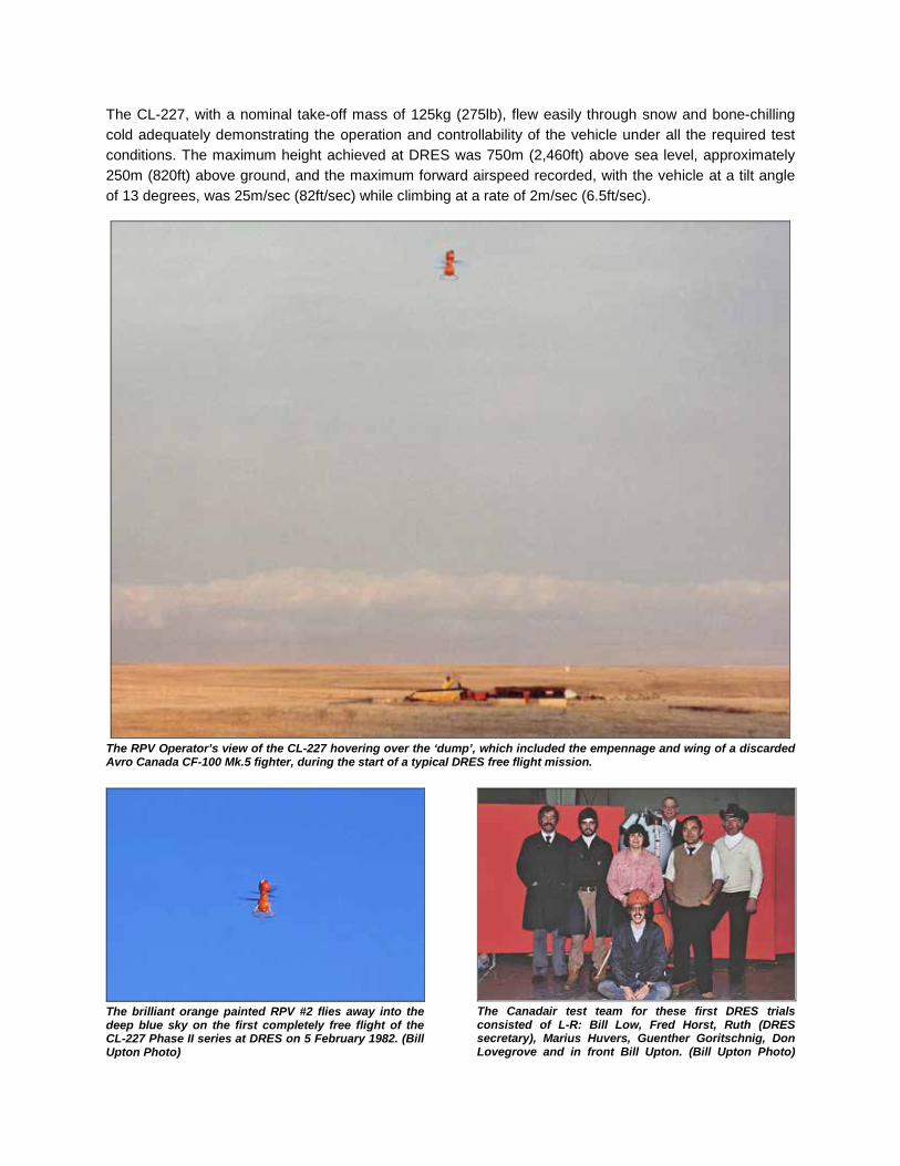
The CL-227, with a nominal take-off mass of 125kg (275lb), flew easily through snow and bone-chilling cold adequately demonstrating the operation and controllability of the vehicle under all the required test conditions. The maximum height achieved at DRES was 750m (2,460ft) above sea level, approximately 250m (820ft) above ground, and the maximum forward airspeed recorded, with the vehicle at a tilt angle of 13 degrees, was 25m/sec (82ft/sec) while climbing at a rate of 2m/sec (6.5ft/sec).
The RPV Operator’s view of the CL-227 hovering over the ‘dump’, which included the empennage and wing of a discarded Avro Canada CF-100 Mk.5 fighter, during the start of a typical DRES free flight mission.
The brilliant orange painted RPV #2 flies away into the deep blue sky on the first completely free flight of the CL-227 Phase II series at DRES on 5 February 1982. (Bill Upton Photo)
The Canadair test team for these first DRES trials consisted of L-R: Bill Low, Fred Horst, Ruth (DRES secretary), Marius Huvers, Guenther Goritschnig, Don Lovegrove and in front Bill Upton. (Bill Upton Photo)

A small numbered target denotes the two-kilometer reference point. Footprints and vehicle tracks are also discernable in this zoomed-in screen capture from the RPV’s B/W video footage.
Off-road vehicular traffic created these tracks in the snow as an exercise for the RPV Pilot to track them to their source, also a screen capture from onboard-recorded video.
During most of these quasi-tactical environment missions, targets and ground vehicle tracks were laid out at specific locations in the snow down the test range, consisting of various types of military ground vehicles and hardware, even such remnants as a derelict Avro Canada CF-100 Canuck fighter aircraft. The emphasis was put on the air vehicle and operators to demonstrate the ability to follow a track, or to station keep above any selected target and perform sensor (real-time TV camera) evaluation. Visual tracking of the vehicles while inflight was made relatively simple by retaining the International Orange paint scheme on RPV’s #2 and #3. Although the little vehicles could be lost visually at a distance greater than 2km (1.2mi) if the outside observer averted his gaze or even blinked, a quick glint of sunlight reflected off the silvery exhaust ducts would readily reveal its location. Tactically, not a good thing, but at this test stage it was acceptable. As an experiment, all of the exterior skin surfaces of RPV #4 were onsite painted in an overall grey “Porch-paint”, obtained from a local hardware store, towards a future assessment of tactical vehicle inflight visual acquisition to compare against the existing hi-viz orange scheme. However, with the crude brush painting of the skins completed, this low-observable experiment was never to be completed here with these particular vehicles. A deployable haul-down reel of thin Kevlar rope was used but once during the DRES trials, and proved that this means of air vehicle retrieval to be both time consuming and impractical for further use. Too many steps in the process were necessary for fair weather and flat terrain operations, let alone adding the extra inconveniences of snow, ice, wind, and possible low RPV fuel state. For this particular exercise and evaluation the RPV was put into a steady high hover over the pre-planned landing area, whereupon the spool of Kevlar rope was dropped – and blown into a deep, soft snowbank by the rotor downwash. Eventually dug out and retrieved by the outside observer, the spool with its rope was then routed through a series of small reversed “J” hooks on a pre-placed steel plate secured via long spikes into the ground. The spool was then carried over some distance to the TOALS trailer and secured to the cable drum on the haul-down winch assembly. The collective was then lowered on the RPV allowing the exterior observer to finally haul the vehicle down to a landing. The haul-down spool assembly, located on the exterior skin of the Control Module, was subsequently removed from all of the vehicles to save weight.

This photo sequence shows RPV #2 taking off on the 5th free flight mission over the barren, cold, winter landscape at DRES, on 9 February 1982. A standard search and track mission was performed successfully this day. (Bill Upton Photos) Although much useful data was gathered during these trials, the two flight worthy air vehicles were lost in separate flight incidents, both related to some degradation of pitch / roll actuator performance. A proposal for the utilization of an emergency parachute recovery system attached to the top of the Power Module was discussed briefly at the test site. Some rough sketches were made and sent back to Montreal, but the idea only received a somewhat cursory examination and limited study, but was never implemented.
This wasn’t one of those days when it was particularly fun to go to work. Here we all are, examining the scattered remnants of crashed RPV #2 on the snow-covered test range of the DRES on 10 February 1982 following its planned, but unsuccessful, high-speed dash attempt. The decapitated Power Module rests forlornly in the foreground. The pummeled main body of the RPV is in the background with rotor blades askew and with the video camera framed in its circular aperture at the bottom of the Control Module. The completely detached orange-painted landing ring lies at the right. (Bill Upton Photo)
On 15 March 1982, a system set-up deployment, free flight demonstration with RPV #3 and equipment retrieval was performed during a heavy snowstorm in front of a large delegation of NATO officials, Canadian DND personnel, United States Marine Corps, and other industry observers. They were all assembled together, huddling uncomfortably, at the leeward side of the DRES Building 15 complex.

A chinook had just arrived during this preparation for the first free flight of RPV #3, on 13 March 1982, at CFB Suffield, turning the frozen tundra into a thick, sticky, smelly, boot-sucking quagmire. Just another hardship to endure for the dedicated flight test team members.
Two days later a heavy snowstorm arrived just in time to prove to NATO observers that these vehicles could fly in almost any type of weather. Again, the test team persevered in these ever changing, minus miserable temperature conditions. The air vehicles, not so much.
More data on the performance envelope of the Phase II RPV under flight conditions was required, however, this had to be obtained without further risk to the two remaining air vehicles. All hardware and personnel were returned home to Canadair to implement a quick, yet comprehensive series of tests related to the confounding actuator loading and failure issue. RPV #4 had been specially instrumented and logged many hours of ground static tests and tether flying monitoring the swashplate loads, which showed that the pitch / roll actuator loads were dynamic and not aerodynamic in origin. Following a detailed study, suspicion fell upon possible grease migration from the blade hub bearings as being the culprit in the loss of the two air vehicles at DRES. In order to further understand the behavior of the blade hub bearings and grease migration leading to the high actuator loading under flight conditions, a test rig was quickly fabricated, per recommendations by Doug Laurie Lean of the National Research Council (NRC) Ottawa. This rig was made to specifically run-in the bearings in representative blade bearing housings. Round the clock operations for a period of weeks simulated various repetitive inflight-loading scenarios with greased and degreased bearing assemblies. Results obtained were analyzed and the major redesign efforts required to rectify the problem of alleviating the loads were deemed too excessive at this point in the programme, however they were to be applied to the Phase III design endeavors. RPV #1 was shortly thereafter fitted with larger and more powerful actuators capable of operations under higher loads and was flown repeatedly on the Canadair tether facility demonstrating satisfactory results. To verify the mechanical modifications and acquire additional aerodynamic data it was then decided to further test these RPVs at the 20 by 20-foot wind tunnel at the NRC facilities in Ottawa. The GCS, TOALS and Vega antenna were to be the same articles that were utilized during the earlier DRES free flight trials. The objectives of these wind tunnel tests were to establish: 1. Trim conditions (RPV tilt angle, cyclic and collective angles) vs forward speed 2. Engine output power vs forward speed 3. Propeller feathering link loads 4. Vibration data 5. RPV stability data

A simple and safety minded test setup was designed and quickly assembled at the efflux section of the NRC M-46 propulsion tunnel by a Canadair advance team and NRC personnel. Tether cables were attached to the vehicle from an overhead beam assembly and a lower winch system, permitting trimmed flight and pseudo free flight conditions with relative safety to the flight hardware. A fixed lower cable centralizer system maintained the air vehicle near the midpoint of the tunnel exhaust during flight.
RPV #1 is shown ‘flying’ in the efflux section of the NRC’s 20 x 20-foot propulsion wind tunnel in October 1982. It is restrained via an upper tether cable, with a haul down tether cable and telemetry harnesses draping down centrally from the Control Module. The mobile GCS is parked off to the side where control of the vehicle was initially exercised via an umbilical cable in lieu of the data link system. Instrumented RPV #4, in a light grey paint scheme, was the principal vehicle used, with orange painted RPV #1 only accomplishing two exploratory ‘flights’. The first of nine wind tunnel lightweight and heavyweight vehicle ‘flights’ commenced in August 1982. These ‘flights’ provided more than 9 hours of total flying time, with the CL-227 eventually reaching a tilt angle of 24 degrees in simulated forward speeds of up to 30m/sec (102ft/sec). The wind for the tunnel operations was normally generated by two powerful Orenda jet engines located in a separate housing nearby, however just one of these engines provided sufficient power for our low-speed test efforts. Additional modifications to preclude grease migration out of the blade hub bearings, a contributing factor towards the loss of RPV’s #2 and #3, were made to the existing air vehicles per data analysis and physical inspections from these wind tunnel tests. Modifications were made to the remaining RPVs towards the preparation for further potential free flight trials and customer demonstrations.
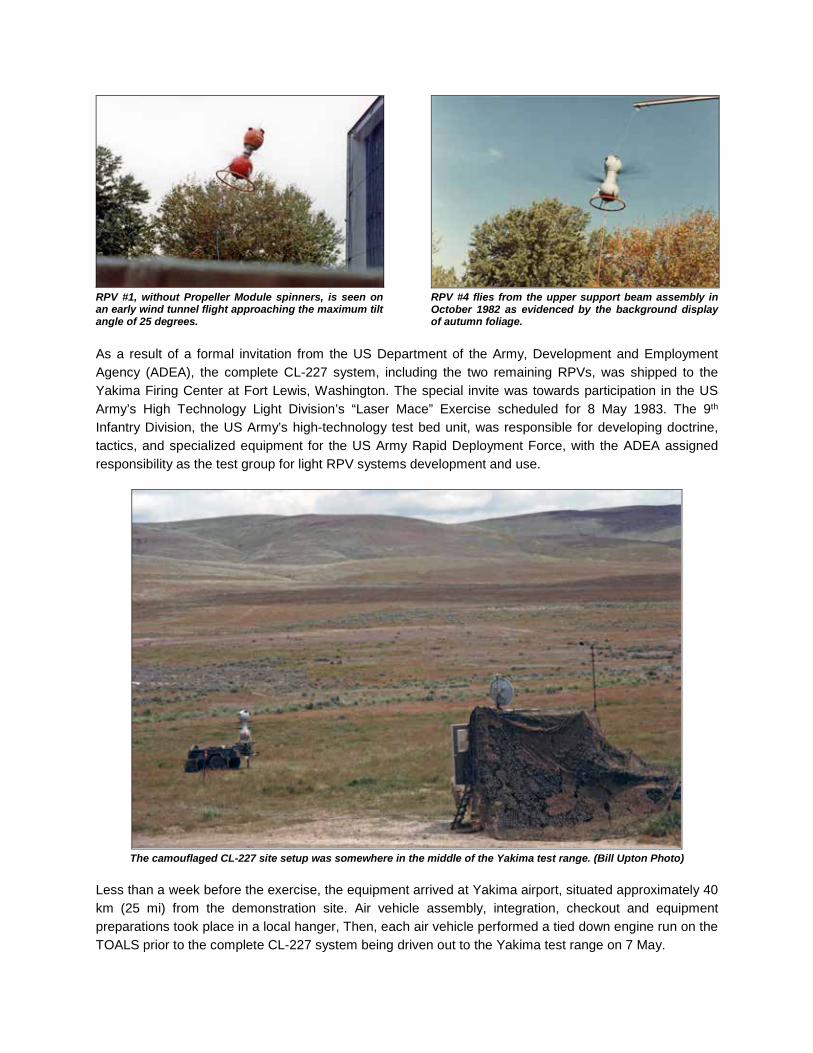
RPV #1, without Propeller Module spinners, is seen on an early wind tunnel flight approaching the maximum tilt angle of 25 degrees.
RPV #4 flies from the upper support beam assembly in October 1982 as evidenced by the background display of autumn foliage.
As a result of a formal invitation from the US Department of the Army, Development and Employment Agency (ADEA), the complete CL-227 system, including the two remaining RPVs, was shipped to the Yakima Firing Center at Fort Lewis, Washington. The special invite was towards participation in the US Army’s High Technology Light Division’s “Laser Mace” Exercise scheduled for 8 May 1983. The 9th Infantry Division, the US Army’s high-technology test bed unit, was responsible for developing doctrine, tactics, and specialized equipment for the US Army Rapid Deployment Force, with the ADEA assigned responsibility as the test group for light RPV systems development and use.
The camouflaged CL-227 site setup was somewhere in the middle of the Yakima test range. (Bill Upton Photo)
Less than a week before the exercise, the equipment arrived at Yakima airport, situated approximately 40 km (25 mi) from the demonstration site. Air vehicle assembly, integration, checkout and equipment preparations took place in a local hanger, Then, each air vehicle performed a tied down engine run on the TOALS prior to the complete CL-227 system being driven out to the Yakima test range on 7 May.

Using just-in-case methodology, the author is seen performing the pre-flight readiness checkout of RPV #1 in the mid-morning in the SELAH DZ at the Yakima Firing Center with numerous Hercules transports landing, taxiing and unloading on the adjacent Selah Airstrip. By flight time in the early afternoon a heavy squall had appeared all but preventing such a detailed checkout from happening. At the start of the rain, the rotor blades were quickly removed and the vehicle was protected with a cover bag. When the “launch now or cancel” order came, the vehicle was ready in mere minutes for flight. It was fortunate that all went well with the earlier checkout. The night before, a clandestine infiltration of ‘enemy’ troops made off with all of the mechanical hardware spares under the ‘watchful’ eyes of guards posted in the GCS nearby. The full-scale exercise demonstrated ground and LAPES offloads of equipment and fast attack vehicles from USAF Hercules transports, simulated bomb runs by F-111 tactical strike aircraft, and interdiction passes by flights of A-10 and F-16 aircraft. Firepower delivery was accomplished into the immediate ‘combat’ arena via slung cargo loads beneath US Army Black Hawk and CH-47D helicopters. Fully equipped troops were disgorged from the interiors of these same helicopters. USMC Cobra helicopter gunships hovered nearby like angry wasps keeping the ‘enemy’ troops’ heads down. Cached beneath the TOALS trailer, the author had a ringside seat to the close quarter’s spectacle, much of which took place in the immediate area, while the rest of the CL-227 crew huddled in the GCS to watch the spectacular show.
A US Army UH-60 Black Hawk helicopter slings in a utility vehicle near the CL-227 site. (Bill Upton Photo)
A small fleet of fast attack craft unload themselves from the C-130 running in the background. (Bill Upton Photo)

The weather soon deteriorated rapidly, and at a break in the now compressed exercise, RPV #1, sporting a tactical lo-viz-grey paint scheme, was ordered to be launched. In high winds, light hail and rain, the Peanut took off and performed a successful post attack recce demonstration of the battle area up to a range of 500m (1,640ft) and from a height of 230m (755ft). The real time television imagery readily revealed hidden ‘enemy’ ground troops and equipment emplacements during the eight-minute mission with no reciprocal notice of the little Peanut flying overhead. The imagery was transmitted live to the attending dignitaries and visitors in the viewing bleacher some 600m (1,969ft) from the take-off site. Recovery was made without incident to the valley floor near the take-off location where later, blue ‘friendly’ and red ‘enemy’ forces troops surrounded and marveled over the little vehicle.
CL-227 Phase II RPV #1 takes off to perform the immediate battle area reconnaissance at Yakima. A light observation helicopter is being readied for flight in the background. The bright da-glo stripes were added to the grey vehicle earlier that day, as an orientation and locating aid to the RPV Pilot and Observer due to the low, similarly grey-colored overcast.
A US Army OH-58 Kiowa observation helicopter took off and flew under the Peanut dramatically witnessed via the onboard down-looking video camera and here, in a still frame, by a Canadair film crew stationed high above on a nearby ridge.
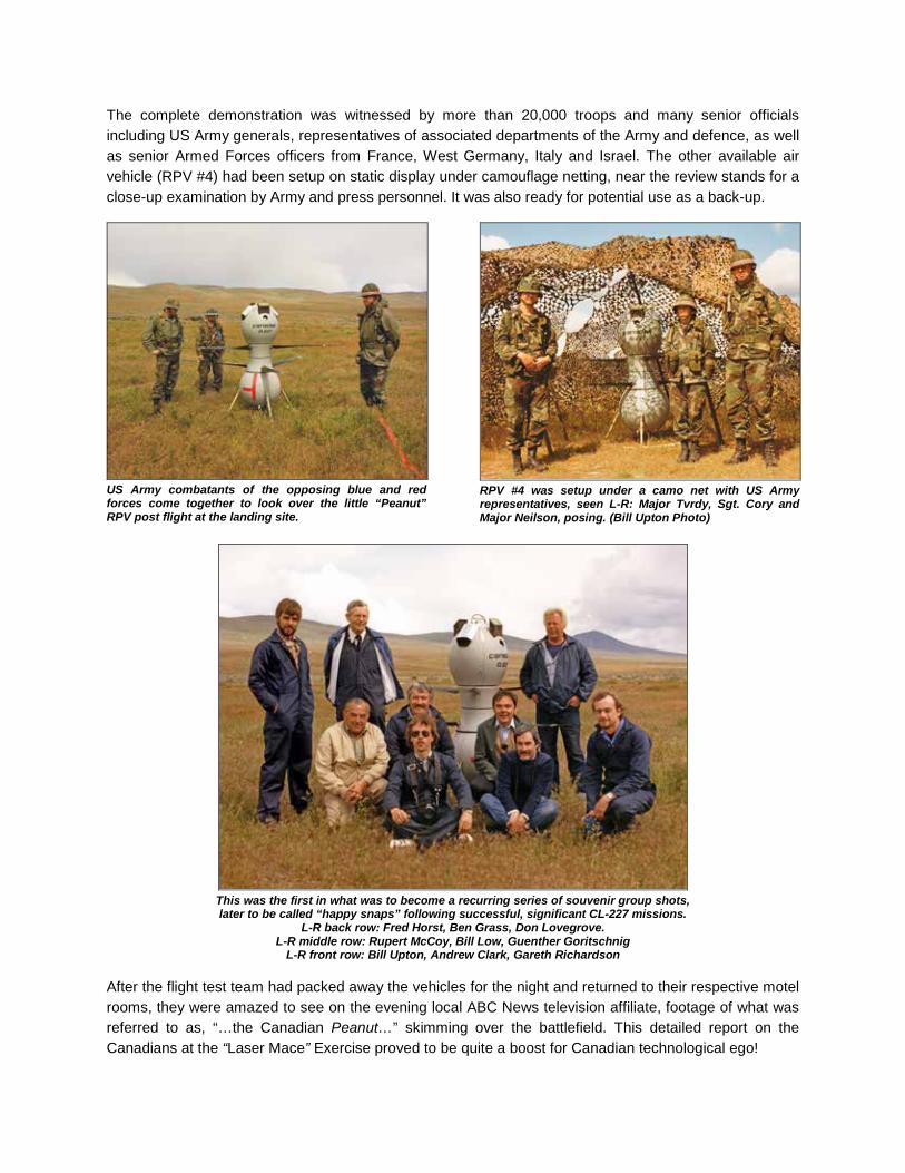
The complete demonstration was witnessed by more than 20,000 troops and many senior officials including US Army generals, representatives of associated departments of the Army and defence, as well as senior Armed Forces officers from France, West Germany, Italy and Israel. The other available air vehicle (RPV #4) had been setup on static display under camouflage netting, near the review stands for a close-up examination by Army and press personnel. It was also ready for potential use as a back-up.
US Army combatants of the opposing blue and red forces come together to look over the little “Peanut” RPV post flight at the landing site.
RPV #4 was setup under a camo net with US Army representatives, seen L-R: Major Tvrdy, Sgt. Cory and Major Neilson, posing. (Bill Upton Photo)
This was the first in what was to become a recurring series of souvenir group shots, later to be called “happy snaps” following successful, significant CL-227 missions.
L-R back row: Fred Horst, Ben Grass, Don Lovegrove. L-R middle row: Rupert McCoy, Bill Low, Guenther Goritschnig
L-R front row: Bill Upton, Andrew Clark, Gareth Richardson After the flight test team had packed away the vehicles for the night and returned to their respective motel rooms, they were amazed to see on the evening local ABC News television affiliate, footage of what was referred to as, “…the Canadian Peanut…” skimming over the battlefield. This detailed report on the Canadians at the “Laser Mace” Exercise proved to be quite a boost for Canadian technological ego!

Local meetings were held with some high ranking armed forces officials with accolades heaped upon the vehicle performance and test team’s effort and professionalism. Yet, no one was willing to cut a cheque or place an order for the little RPV system at this time. It was apparent that everyone wanted to see these unique little vehicles perform, and would come up with some funding to do so, but that was the extent of their interests, or so it appeared. This scenario played out frequently and frustratingly for the design and test team members over the ensuing years. With that highly successful public demonstration completed, further free flight trials were deemed unnecessary. A few more tether tests were achieved to finalize some engineering data requirements, and then Phase II was effectively completed. In all, 13 free flight missions comprising approximately 1 hr. 40 min. of flight time were performed utilizing RPV’s #1, 2 and 3, and more than 100-tether flights were performed with all four of the vehicles. The Phase II system proved to be a valuable tool for exploring the air vehicle flight envelope and operational concepts of such a system, validating much of the original work and studies on which the design was founded. Engineering preparations then began in earnest during the remainder of 1983 towards the start of the new CL-227 Phase III full-scale development programme. All of the remaining WR-34 engines were removed from their respective Power Modules and were returned to Williams International for use on other projects, as Canadair had not purchased them outright. A competition had been held among Canadair employees in February 1984 towards finding a suitable official name for the CL-227 system and Sentinel was selected as the overall winner. The Phase II RPV #1 was repainted and annotated with the new Sentinel logo as a precursor to the Phase III ‘look’, and PR photos were taken and released by August 1984. However, no matter the name, whether it was Dynacopter, CL-227 or Sentinel, it would always remain the Peanut to those who designed, tested, flew, knew and viewed any of these vehicles.
The Phase II RPV #4 had a major modification performed to its Power Module for engineering studies solely to represent the proposed final version shape of the upcoming Phase III Sentinel design. It was never flown again, but was soon relegated as a travelling Marketing Department tool, most significantly during a Trans-Pacific voyage aboard HMCS Huron (DDH 281) from 28 April to 28 July 1988. An official plaque was designed and presented by Canadair to D-2 Squadron to commemorate the exercise and the first ocean voyage of the pseudo-CL-227 Sentinel on a Canadian naval vessel. Following its return to home shores, RPV #4 was now no longer required
for any use by Canadair, so it was presented to and last seen on display, with full Sentinel markings, at the Combat Training Center at CFB Gagetown in New Brunswick. Somewhat less desirable, destructive disposal plans waited for all of the remaining, and now deemed obsolete, CL-227 RPVs that were still residing in storage at the Canadair facilities.

Here is RPV #4 mocked-up as the CL-227 Sentinel RPV, as a static display exhibit in a hallway juncture at the Royal Regiment of the Canadian Artillery School in the J-7 Normandy Building of the Combat Training Center at CFB Gagetown, NB. The unique larger and modified Power Module is readily apparent. A descriptive information plaque is mounted on the wall behind the vehicle. (Photo by Private Mathew Gregory, Canadian Military Engineers Museum, September 2009)
This is an artist’s concept of what a possible sea-borne scenario may have looked like if this type of vehicle was to be deployed for operations aboard a Canadian Destroyer, in this case HMCS MacKenzie (DDE 261). The vehicle is seen being landed to a flat area aft utilizing a simple haul-down method similar to that first tried out with the Phase I vehicle in November 1980.

CL-227 PHASE II FREE FLIGHT LOG
DATE LOCATION FLT No.
RPV No. FLT TIME REMARKS
03 Dec. 1981 Canadair 1 2 05 minutes Check flight, no spinners 14 Dec. 1981 Canadair 2 2 04 minutes Demo, used Vega System 15 Dec. 1981 Canadair 3 2 09 minutes Demo, used Vega System 16 Dec. 1981 Canadair 4 2 07 minutes Demo, used Vega System
02 Feb. 1982 DRES, Alberta 5 2 06 minutes Kevlar lower tether attached 04 Feb. 1982 DRES, Alberta 6 2 13 minutes Kevlar lower tether attached 05 Feb. 1982 DRES, Alberta 7 2 16 minutes First completely free flight 08 Feb. 1982 DRES, Alberta 8 2 04 minutes -20° C cold soak free flight 09 Feb. 1982 DRES, Alberta 9 2 20 minutes Fuel consumption check flight 10 Feb. 1982 DRES, Alberta 10 2 03 minutes High speed dash flight - crash
13 March 1982 DRES, Alberta 11 3 05 minutes No onboard camera image, observer talk down to landing
15 March 1982 DRES, Alberta 12 3 05 minutes NATO Demo – crash in storm
08 May 1983 Yakima, Washington 13 1 08 minutes 9th I.D. “Laser Mace” Exercise
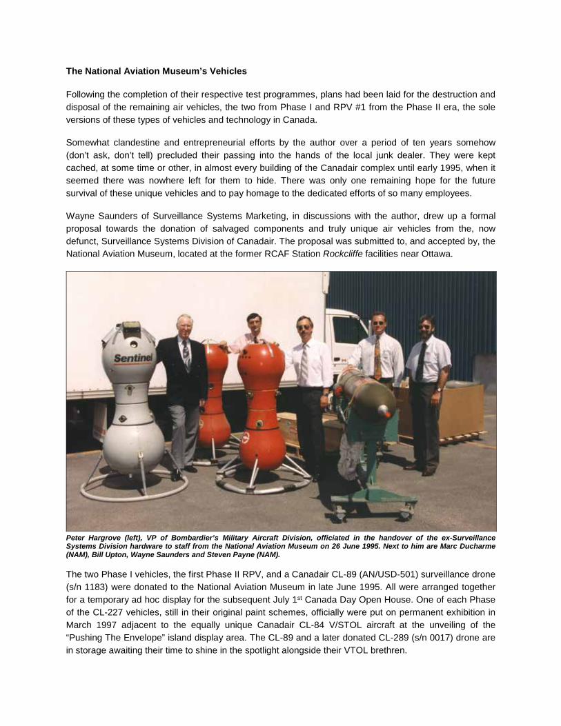
The National Aviation Museum’s Vehicles Following the completion of their respective test programmes, plans had been laid for the destruction and disposal of the remaining air vehicles, the two from Phase I and RPV #1 from the Phase II era, the sole versions of these types of vehicles and technology in Canada. Somewhat clandestine and entrepreneurial efforts by the author over a period of ten years somehow (don’t ask, don’t tell) precluded their passing into the hands of the local junk dealer. They were kept cached, at some time or other, in almost every building of the Canadair complex until early 1995, when it seemed there was nowhere left for them to hide. There was only one remaining hope for the future survival of these unique vehicles and to pay homage to the dedicated efforts of so many employees. Wayne Saunders of Surveillance Systems Marketing, in discussions with the author, drew up a formal proposal towards the donation of salvaged components and truly unique air vehicles from the, now defunct, Surveillance Systems Division of Canadair. The proposal was submitted to, and accepted by, the National Aviation Museum, located at the former RCAF Station Rockcliffe facilities near Ottawa.
Peter Hargrove (left), VP of Bombardier’s Military Aircraft Division, officiated in the handover of the ex-Surveillance Systems Division hardware to staff from the National Aviation Museum on 26 June 1995. Next to him are Marc Ducharme (NAM), Bill Upton, Wayne Saunders and Steven Payne (NAM). The two Phase I vehicles, the first Phase II RPV, and a Canadair CL-89 (AN/USD-501) surveillance drone (s/n 1183) were donated to the National Aviation Museum in late June 1995. All were arranged together for a temporary ad hoc display for the subsequent July 1st Canada Day Open House. One of each Phase of the CL-227 vehicles, still in their original paint schemes, officially were put on permanent exhibition in March 1997 adjacent to the equally unique Canadair CL-84 V/STOL aircraft at the unveiling of the “Pushing The Envelope” island display area. The CL-89 and a later donated CL-289 (s/n 0017) drone are in storage awaiting their time to shine in the spotlight alongside their VTOL brethren.
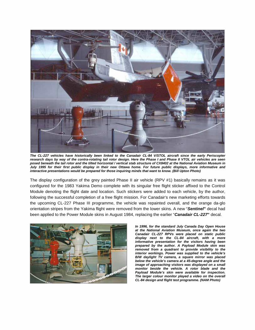
The CL-227 vehicles have historically been linked to the Canadair CL-84 V/STOL aircraft since the early Periscopter research days by way of the contra-rotating tail rotor design. Here the Phase I and Phase II VTOL air vehicles are seen posed beneath the tail rotor and the tilted horizontal / vertical stab structure of CX8402 at the National Aviation Museum in July 1995 for their first public display in their new Ottawa home. For future public displays, more informative and interactive presentations would be prepared for those inquiring minds that want to know. (Bill Upton Photo) The display configuration of the grey painted Phase II air vehicle (RPV #1) basically remains as it was configured for the 1983 Yakima Demo complete with its singular free flight sticker affixed to the Control Module denoting the flight date and location. Such stickers were added to each vehicle, by the author, following the successful completion of a free flight mission. For Canadair’s new marketing efforts towards the upcoming CL-227 Phase III programme, the vehicle was repainted overall, and the orange da-glo orientation stripes from the Yakima flight were removed from the lower skins. A new “Sentinel” decal had been applied to the Power Module skins in August 1984, replacing the earlier “Canadair CL-227” decal.
In 1996, for the standard July Canada Day Open House at the National Aviation Museum, once again the two Canadair CL-227 RPVs were placed on static public display next to the CL-84 aircraft, with a more informative presentation for the visitors having been prepared by the author. A Payload Module skin was removed from a quadrant to provide visibility to the interior workings. Power was supplied to the vehicle’s B/W daylight TV camera, a square mirror was placed below the vehicle’s camera at a 45-degree angle and the image of approaching visitors was displayed on a small monitor beside the vehicle. A rotor blade and the Payload Module’s skin were available for inspection. The larger colour monitor played a video on the overall CL-84 design and flight test programme. (NAM Photo)
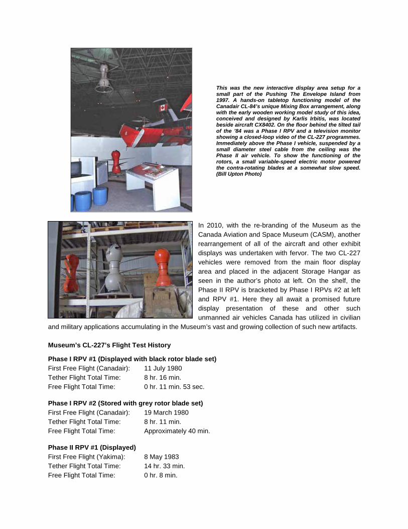
This was the new interactive display area setup for a small part of the Pushing The Envelope Island from 1997. A hands-on tabletop functioning model of the Canadair CL-84’s unique Mixing Box arrangement, along with the early wooden working model study of this idea, conceived and designed by Karlis Irbitis, was located beside aircraft CX8402. On the floor behind the tilted tail of the ’84 was a Phase I RPV and a television monitor showing a closed-loop video of the CL-227 programmes. Immediately above the Phase I vehicle, suspended by a small diameter steel cable from the ceiling was the Phase II air vehicle. To show the functioning of the rotors, a small variable-speed electric motor powered the contra-rotating blades at a somewhat slow speed. (Bill Upton Photo)
In 2010, with the re-branding of the Museum as the Canada Aviation and Space Museum (CASM), another rearrangement of all of the aircraft and other exhibit displays was undertaken with fervor. The two CL-227 vehicles were removed from the main floor display area and placed in the adjacent Storage Hangar as seen in the author’s photo at left. On the shelf, the Phase II RPV is bracketed by Phase I RPVs #2 at left and RPV #1. Here they all await a promised future display presentation of these and other such unmanned air vehicles Canada has utilized in civilian
and military applications accumulating in the Museum’s vast and growing collection of such new artifacts. Museum’s CL-227’s Flight Test History Phase I RPV #1 (Displayed with black rotor blade set) First Free Flight (Canadair): 11 July 1980 Tether Flight Total Time: 8 hr. 16 min. Free Flight Total Time: 0 hr. 11 min. 53 sec. Phase I RPV #2 (Stored with grey rotor blade set) First Free Flight (Canadair): 19 March 1980 Tether Flight Total Time: 8 hr. 11 min. Free Flight Total Time: Approximately 40 min. Phase II RPV #1 (Displayed) First Free Flight (Yakima): 8 May 1983 Tether Flight Total Time: 14 hr. 33 min. Free Flight Total Time: 0 hr. 8 min.

Canadair CL-227 PHASE III – Preproduction Tactical Development UAV What was to become the definitive and final variant of the CL-227 family began to take shape in the minds of the Canadair Surveillance Systems Division (SSD) design engineers while the last of the Phase II models was being returned from its successful US Army demonstration in Washington. Full scale engineering design and development to military standards of the Phase III programme, using the Cook-Craigie plan, was formally initiated in 1984 with the aim of taking the CL-227 into a preproduction stage, with hardware ready to sell and deliver to potential customers. The primary flight test objectives were to establish the stability and maneuver flight envelopes, and verify performance towards development and demonstration of a tactical, now termed Unmanned Air Vehicle (UAV) system. In January 1986, the federal government contributed more than $30 million under the Defence Industry Productivity Programme (DIPP), toward the cost of development and production of the Phase III system. The contract called for the manufacture of ten air vehicles, two Ground Control Stations (GCS), ground support systems and six non-tactical (look-down daylight TV camera) payloads for preliminary flight test and demonstration purposes. Less commercially
available, and more MIL-Spec components and qualification standards were to be used in the makeup of the air vehicle and support equipment. To verify initial design development, a manually functional, full-scale form and fit mockup was constructed in May 1986, then numerous engineering test rigs were developed to qualify all necessary components prior to their installation on the actual air vehicle (A/V). One of the largest rigs, the Propeller Module Test Rig (PMTR), was located in a little used hangar, known as BLDG 208, at Plant 2. Initially powered by the WTS34 engine with its fuel tank assembly installed, the Propeller Module, with all of its mechanically assembled components, was to be run-in for a period of hours to break-in the assembly and verify the integrity of the seals, gaskets and other rotating parts. One propeller Module performed a 200-hour endurance run on the PMTR, with all subsequent units performing a “green-run” prior to their assembly in an air vehicle. In order to expedite the tests more efficiently the engine/fuel tank assembly was later replaced with a hydraulic pump arrangement. With the improvements came the necessity to refine the design and drawing methods to a more efficient way of producing drawings suitable for production purposes. The tried and true ways of the staunch pencil pushers slowly made progress towards the computer-aided design and manufacturing (CADAM) process newly implemented in a few Canadair engineering departments. The stepped air vehicle development programme from the CL-227 Phase I to Phase II, and on to the current Phase III was necessary due to small budgets and manpower, and to slowly progress to an advanced stage design that could better meet prospective new customer’s anticipated needs.
The complete interior workings of the CL-227 Phase III mock-up included a full WTS34 engine mock-up at the top supplied by Williams International that would be enclosed by the annular fuel tank assembly. Later-on, this overall mock-up would become an integral part of the continuous Phase III ground test programme as the Avionics and Controls Test Rig. As such, software updates could be tested and verified on a hardware rig prior to being introduced to the actual air vehicles.

The step-by-step growth in vehicle size and mass resulted in increases in both endurance and useable payload capability. Improvements and increased capability in the vehicle design also stemmed in part from evolving statements of requirements from potential users that eventually led to the changes that were incorporated to provide sufficient performance and growth potential. These improvements included: Ø Increased fuel capacity Ø Reduced structural mass Ø Increased payload carrying capability Ø Adaptation of additional payload types Ø Increased engine power Ø Larger rotor blades Ø Enhanced continuous navigation capability Ø Improved range and endurance Ø Improved maintainability and reliability
The tried and proven readily interchangeable modular concept was maintained in the design of this Phase as well, with the primary components consisting of the Power Module, Propeller Module (integrated with the payload interface, formerly called the Control Module) and the Payload Module. The Power Module was composed of a 50 litre (11 Imp. gallon) annular fuel tank encompassing a small gas turbine engine with integral speed reducing differential gearbox, starter/alternator assembly, ignition and fuel control systems. The powerplant chosen for the Phase III vehicle was the 50 shaft-horsepower Williams International WTS34-16 turboshaft engine that had the
capability of running on a variety of fuels. As with the Phase II vehicles, commercial grade diesel fuel was principally used. The vertically mounted engine incorporated the air intakes at the bottom with the exhaust being emitted at the top, effectively reducing the UAV’s infrared (IR) signature. This engine installation design harks back to the Saurer GT15 gas turbine engine mounting in the earlier CL-227 Dynacopter concept. Sixteen engines were built with one being tested to over 200 hours of running. The first flight-rated engine was delivered in mid-December 1986 and the first air vehicle run with an engine occurred in January 1987. Mechanically interfacing the Power Module and Propeller Module is the robust Magnetic Particle Clutch (MPC) housing. This structural component contained two magnetic particle clutch assemblies, directly connected to the output shafts of the engine gearbox, then through shafts and gears to the upper and lower rotor hubs. The assembly provided precise yaw control of the vehicle via differential rotor torque. Energizing the magnetic powder in one clutch transfers the torque to the other clutch with the unequal torque resulting in the necessary yaw control. The complete MPC system was thoroughly bench tested for reliability and endurance on a specialized MPC Test Rig. The MPCs efficiently replaced the friction disc and actuator driven yaw-braking system design used previously in the Phase I and Phase II vehicles that were prone to oil-contaminated slippage failures.
The first fuel tank and Propeller Module for the CL-227 Phase 3 programme are officially handed over to the engineering group from the manufacturing shop on 12 November 1986.
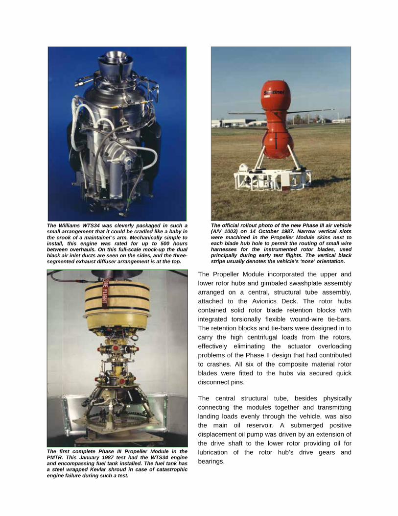
The Williams WTS34 was cleverly packaged in such a small arrangement that it could be cradled like a baby in the crook of a maintainer’s arm. Mechanically simple to install, this engine was rated for up to 500 hours between overhauls. On this full-scale mock-up the dual black air inlet ducts are seen on the sides, and the three-segmented exhaust diffuser arrangement is at the top.
The official rollout photo of the new Phase III air vehicle (A/V 1003) on 14 October 1987. Narrow vertical slots were machined in the Propeller Module skins next to each blade hub hole to permit the routing of small wire harnesses for the instrumented rotor blades, used principally during early test flights. The vertical black stripe usually denotes the vehicle’s ‘nose’ orientation.
The Propeller Module incorporated the upper and lower rotor hubs and gimbaled swashplate assembly arranged on a central, structural tube assembly, attached to the Avionics Deck. The rotor hubs contained solid rotor blade retention blocks with integrated torsionally flexible wound-wire tie-bars. The retention blocks and tie-bars were designed in to carry the high centrifugal loads from the rotors, effectively eliminating the actuator overloading problems of the Phase II design that had contributed to crashes. All six of the composite material rotor blades were fitted to the hubs via secured quick disconnect pins. The central structural tube, besides physically connecting the modules together and transmitting landing loads evenly through the vehicle, was also the main oil reservoir. A submerged positive displacement oil pump was driven by an extension of the drive shaft to the lower rotor providing oil for lubrication of the rotor hub’s drive gears and bearings.
The first complete Phase III Propeller Module in the PMTR. This January 1987 test had the WTS34 engine and encompassing fuel tank installed. The fuel tank has a steel wrapped Kevlar shroud in case of catastrophic engine failure during such a test.

Three swashplate linear actuators, at 120 degree spacing, were arranged on the periphery of the central tube with the complete swashplate mechanism located immediately above. The air start line, from the exterior connection up to the engine was also routed through the central tube. The bottom of the central tube was attached to the Avionics Deck that was segregated into four separate quadrants due to the structural arrangement of the four landing leg housings. The bottom of the landing leg housings provided the mounting point for the Payload Module attachment ring thus completing the principal structural makeup of the vehicle. Immediately above the Avionics Deck, attached to the rotating lower hub assembly was a honeycomb disc assembly incorporating small metal fins, radially mounted on the underside. As the hub/disc rotated, the assembly acted as a cooling fan to blow overboard the heat generated by the avionics boxes when they were powered up. When the rotor blades were not turning, a separate exterior mounted cooling fan blower assembly was temporarily attached onto the outer skins to dissipate the heat. It was removed from the vehicle immediately prior to air start initiation. One Avionics Deck quadrant was dedicated solely to mechanical components. These included the air start quick-disconnect coupling; main power umbilical connector interface; and the haul-down spool release assembly. The haul-down system was first tested during the Phase II programme with disappointing results. This design was similar in approach and theory to the Phase II design, incorporating a white Teflon spool with thin diameter Kevlar line wound around it. The spool was a fixed attachment flush to the exterior skin and would be ejected, retrieved by ground personnel, and attached to a motorized winch on a ground-based vehicle. Then the air vehicle would be winched down to a landing. At least, that was the premise. The basic idea was sound, but air vehicle operator judgement prevailed in their perceived capabilities to land the air vehicle without mechanical aids, and so the unit was never used operationally. The empty spool was retained on the skin housing simply for aerodynamic purposes. This air vehicle concept variant grew once again, compared to its predecessors, now standing 1.77m (5.8ft) high with a rotor diameter of 2.8m (9.2ft). Landing rings, familiarly seen in the past two CL-227 conceptions, were dispensed with in Phase III due to payload visibility restrictions and in an aid towards reducing aerodynamic drag. Four readily removable composite material landing legs with ovoid-shaped feet were incorporated in lieu. Later a specialized set of legs with lock-down feet would be used for naval trials. White painted, solid metal legs with rounded Teflon feet were used for all tether test purposes. INITIAL PERFORMANCE SPECIFICATIONS With the maximum take-off weight established at 190kg (420lb), the vehicle had a proposed target range of up to 30km (19mi) with a loiter capability. This was continually updated during the Phase III programme due to potential customer’s requirements and eventually became 60km (37.3mi). It was to be capable of operating up to an altitude of 3,000m/ASL (9,840ft/ASL), perform at speeds from hover up to 70 knots (130km/h / 80.8mph) and have an endurance of up to 4 hours (dependent on type of payload carried). The maximum payload capacity was set at 45kg (100lb) which fell well into the realm of using payloads that had been conceived for other small UAVs, notably Lockheed’s cancelled Aquila system. Proposed payloads considered included a small, stabilized RCA daylight TV camera (similar to Phase II); a gimballed forward-looking infrared (FLIR), or real-time daylight television (DTV) sensor; a communications relay or an electronics counter-measures package.
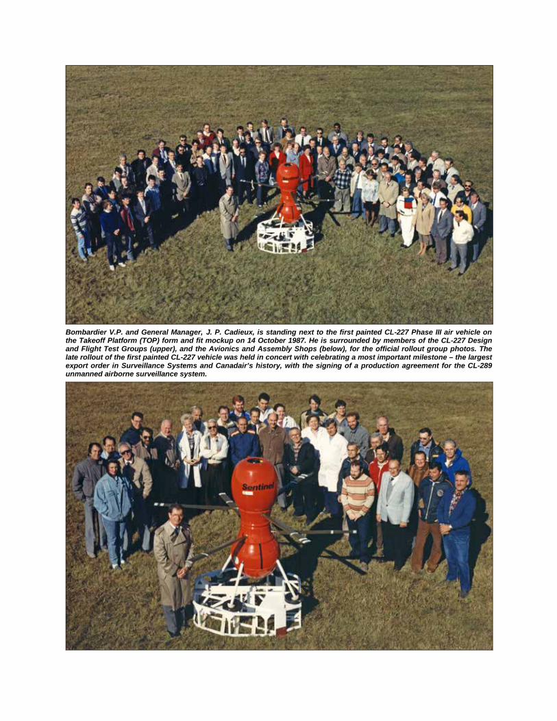
Bombardier V.P. and General Manager, J. P. Cadieux, is standing next to the first painted CL-227 Phase III air vehicle on the Takeoff Platform (TOP) form and fit mockup on 14 October 1987. He is surrounded by members of the CL-227 Design and Flight Test Groups (upper), and the Avionics and Assembly Shops (below), for the official rollout group photos. The late rollout of the first painted CL-227 vehicle was held in concert with celebrating a most important milestone – the largest export order in Surveillance Systems and Canadair’s history, with the signing of a production agreement for the CL-289 unmanned airborne surveillance system.

During this period of time, the modest success enjoyed by the world leading Surveillance Systems Division, with the acclaimed accomplishments of the production lines of the CL-89, and CL-289 recoverable surveillance drones for NATO, and now, the newer CL-227 systems, was not being shared by the rest of the company. Canadair was going through some rather difficult times as a direct result of taking on the mammoth task of introducing and producing the world’s first wide-body business jet, the Canadair CL-600 Challenger. On Monday 18 August 1986, all employees, and then the general public, found out that Bombardier Inc. of Montreal had purchased Canadair from the Federal Government. Bombardier seeing this purchase as a positive move towards expanding its expertise in the aviation industry, followed this with similar purchases of struggling Short Brothers in Ireland, the Learjet Corporation in Kansas and completed its aviation foursome by acquiring long-troubled de Havilland Canada in March 1992. The formal term “air vehicle” was nominally used in text, the acronym “A/V” employed only when in concert with a particular air vehicle and its serial number, and “vehicle” generally in speech. Serial numbers were allocated to the ten built Phase III air vehicles and the associated modules ranging from 1001 to 1010, commonly being annotated as A/V 1001 to A/V 1010. A few years later two additional air vehicles (1011 and 1012) were constructed using a combination of crashed or incidented vehicles plus available spare parts components. During tethered, and later free flight testing, many of the air vehicles also acquired “nicknames” by some of the test crew and these, or their allocated A/V serial number, were annotated in black immediately to the right of the main umbilical door on the Control Module.
A/V 1001 A/V 1007 “Lucky 7” A/V 1002 “Junkyard” A/V 1008 “8 Ball” A/V 1003 “Sweaty Betty” A/V 1009 “1009” A/V 1004 A/V 1010 “MX” A/V 1005 “Number Five” A/V 1011 “1011” A/V 1006 “Sea Six” A/V 1012 “1012”
The primary objectives of the CL-227 Phase III flight test programme were to: Ø Determine and verify the basic performance Ø Verify the autopilot software (i.e.: the control laws and performance) Ø Determine and verify autonomous navigation capability and accuracy Ø Demonstrate reliable operations in a variety of environmental conditions. Following the component test rigs and ground-based static and bench test work of all the major vehicle components, actual flight-testing was slated to begin. The CL-227 Phase III flight test programme was organized in the following stages: Ø Tether tests at the Canadair/Bombardier facilities in Montreal Ø Wind tunnel tests at the NRC facilities in Ottawa Ø Initial free flight tests at the Canadair/Bombardier facilities Ø Free flight tests and envelope expansion flights primarily at the DRES, Alberta, test range On 12 November 1986, the first Phase III vehicle was handed over by the manufacturing and assembly shops to the design and test group to start preliminary integration and test work. The first three air vehicles were at first specially configured and instrumented in order to obtain specific engineering data on each vehicle during static ground, tethered and free flight tests. One way of visually identifying these instrumented vehicles, was by way of small vertical slots machined in the Propeller Module skins, next to each of the rotor hubs. The data from the Development Telemetry system was transmitted to the test engineers via the air vehicle’s dual mode (data/video) video transmitter.

Due to the extra mass of the instrumentation, harnesses and mechanical equipment installed in these three vehicles, along with the multitude of tether flight support hardware, the original forecast performances would obviously not be met. That usually meant that many of the tether tests required that the vehicle not be fully fuelled and more test flights would be run for shorter periods of time in order to meet run-in or endurance specifications. A complete re-fitting of the existing Tether Test facility was warranted for the upcoming tether tests of the new vehicles. A major modification involved the addition of a large wooden platform around the TOP for evaluating the take-off and landing characteristics and control of the air vehicle in ground effect. Exterior light fixtures and TV cameras trained on the TOP area and at the air vehicle once hovering flight was achieved, permitted round-the-clock or night operations as required. In June 1987, a series of bladeless runs were conducted with A/V 1001 at the Tether Test facility to verify all air vehicle and newly revamped test site systems were functioning as desired prior to attempting an actual tethered flight with rotor blades installed. This was the norm for all subsequent air vehicles that came available in the production run.
The first tethered flight of the new Phase III UAV, A/V 1001, took place from the remodeled and modernized CL-227 Tether Test facility on 17 June 1987. The Control Module and Propeller Module skins were not installed for this and some of the following early test flights to permit the viewing and recording of any anomalies by the video camera mounted on the tether tower at the nominal hover height.
Compared to the Phase I and II tether test setup, this series of UAVs utilized a rather robust upper and lower tether attachment arrangement. The normal landing legs were replaced with a heavy-duty specialized set with cupped nylon feet. Stainless steel shields are installed on the lower surfaces of the upper tether frame tubes to protect the metal from the heat of the engine’s upward exhaust.
The first air vehicles remained basically unpainted at first for most of the early tether flight tests, with visible sections of yellow or green basically being the standard colours of the various primers used on the different materials that made up the exterior surfaces. The principal colour chosen for the final exterior finish was, as with the previous CL-227 variants, International Orange. All of the necessary tether test support hardware installed on an air vehicle was painted a flat white. By the end of August 1987, a wind tunnel test programme was started in the 20 by 20-foot exhaust of the M46 propulsion tunnel at the familiar NRC facilities in Ottawa. The main goal of these tests was to demonstrate controllable forward speed flight and determine/rectify any unknown problems prior to attempting the first free flight. The test setup at the NRC emulated somewhat the former CL-227 Phase II arrangement at that complex. From August to October 1987 some 21 test ‘flights’ were conducted demonstrating controllability in wind speeds of up to 58 knots (107km/h / 67mph) and at tilt angles approaching 30 degrees. Also examined were exhaust gas reingestion, air flow around the body contours (tuft tests), rotor blade and pitch links loads, and the vibration environment.

It was decided early on that wind tunnel tests should be performed in this Phase prior to committing any air vehicle to a free flight. The previous Phase II wind tunnel setup at the NRC was reused, with modifications to suit the heavier vehicles and equipment. Here again is A/V 1001 in ‘flight’ during a test on 15 September 1987.
A series of ‘flights’ were performed with the air vehicle tufted to see air flow patterns over the skin surfaces. The black wool tufts and tape add to the bizarre colour makeup of A/V 1001 during these tunnel tests. The maximum vehicle tilt angle permissible during flight was limited to 30 degrees due to oil system restrictions.
Due to the availability of air vehicles, additional engineering test personnel, and multiple support systems, the NRC Ottawa-based wind tunnel tests were run concurrently with the Montreal based tether tests thus saving valuable time and cost. Reduced data from the numerous tether and wind tunnel tests confirmed the soundness of the design and quickly cleared the way towards attempting the first Phase III free flight.
The first free flight of a Phase III air vehicle took place from the western part of the former Cartierville airfield at the Canadair/Bombardier facilities on 20 November 1987. On this cold, drab day, A/V 1003 performed a flawless 3-minute flight without the Power Module top cover installed due to an early air start arrangement. It was controlled via the Vega data link system and, as in the past, incorporated a Kevlar tether safety cable to prevent inadvertent intrusion into the approach path of nearby Dorval International Airport. This flight demonstrated the ability of the vehicle to translate, hover and land under full manual control.

This group portrait commemorates completion of training of the primary group of DND personnel at the Tether Test site in December 1987. Canadair/Bombardier trainers included L-R: Vic Chang, Dave Cool, Ray Atkins, Steve Raff, A/V 1001, Guenther Goritschnig, Gareth Richardson, Mark Roe, Yves Roy, Bill Upton, Tracy Lloyd, Kevin McCarthy and Ron Leblanc.
A staged military presentation of a proposed typical field arrangement of the ground support vehicles required for the Phase III programme. A deuce-and-a-half truck carries the GCS and pulls a trailer with the main power generator. Offset to the rear is another trailer with the RGT (Vega antenna). The TLV, a modified military General Motors utility cargo truck, has unloaded a tactical painted air vehicle onto the TOP and military personnel are shown installing the A/V’s rotor blades.
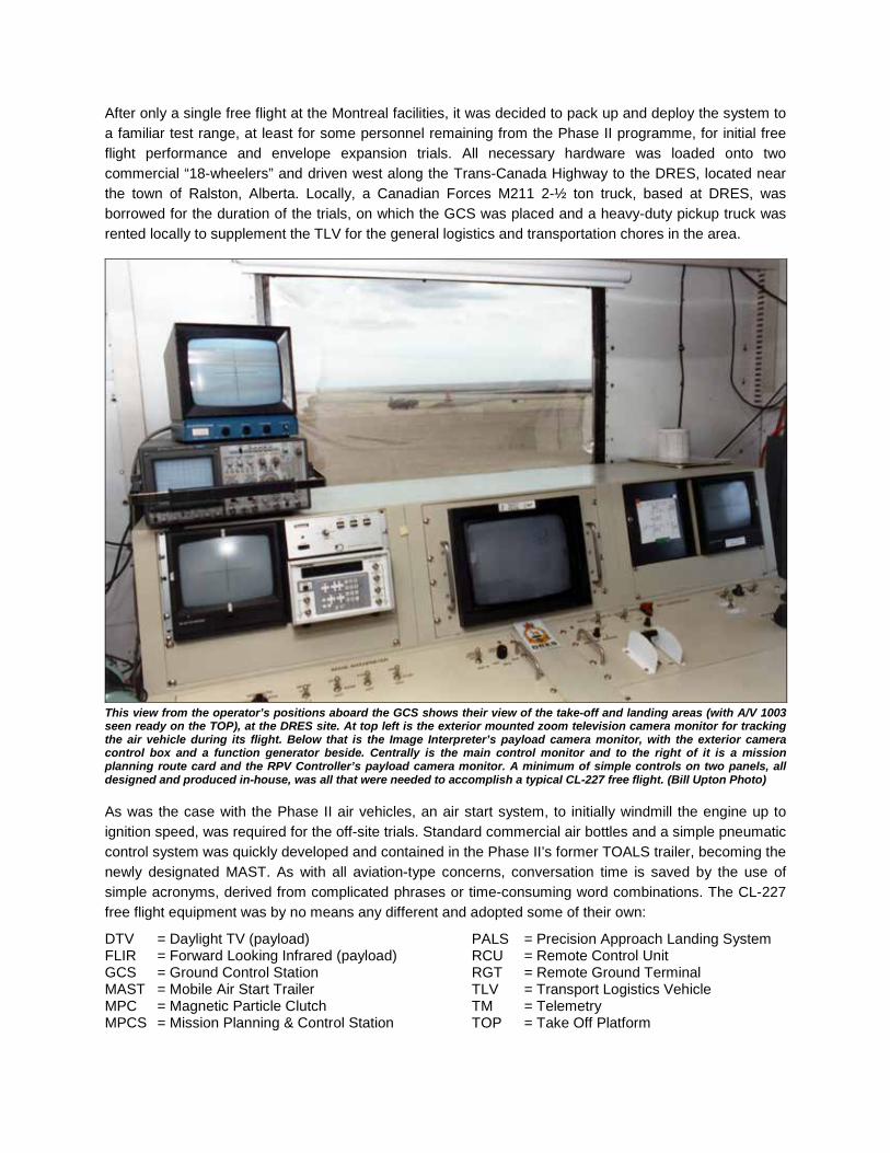
After only a single free flight at the Montreal facilities, it was decided to pack up and deploy the system to a familiar test range, at least for some personnel remaining from the Phase II programme, for initial free flight performance and envelope expansion trials. All necessary hardware was loaded onto two commercial “18-wheelers” and driven west along the Trans-Canada Highway to the DRES, located near the town of Ralston, Alberta. Locally, a Canadian Forces M211 2-½ ton truck, based at DRES, was borrowed for the duration of the trials, on which the GCS was placed and a heavy-duty pickup truck was rented locally to supplement the TLV for the general logistics and transportation chores in the area.
This view from the operator’s positions aboard the GCS shows their view of the take-off and landing areas (with A/V 1003 seen ready on the TOP), at the DRES site. At top left is the exterior mounted zoom television camera monitor for tracking the air vehicle during its flight. Below that is the Image Interpreter’s payload camera monitor, with the exterior camera control box and a function generator beside. Centrally is the main control monitor and to the right of it is a mission planning route card and the RPV Controller’s payload camera monitor. A minimum of simple controls on two panels, all designed and produced in-house, was all that were needed to accomplish a typical CL-227 free flight. (Bill Upton Photo) As was the case with the Phase II air vehicles, an air start system, to initially windmill the engine up to ignition speed, was required for the off-site trials. Standard commercial air bottles and a simple pneumatic control system was quickly developed and contained in the Phase II’s former TOALS trailer, becoming the newly designated MAST. As with all aviation-type concerns, conversation time is saved by the use of simple acronyms, derived from complicated phrases or time-consuming word combinations. The CL-227 free flight equipment was by no means any different and adopted some of their own:
DTV = Daylight TV (payload) FLIR = Forward Looking Infrared (payload) GCS = Ground Control Station MAST = Mobile Air Start Trailer MPC = Magnetic Particle Clutch MPCS = Mission Planning & Control Station
PALS = Precision Approach Landing System RCU = Remote Control Unit RGT = Remote Ground Terminal TLV = Transport Logistics Vehicle TM = Telemetry TOP = Take Off Platform

This is the take-off and landing (white squared outlined area in the left foreground) area setup at DRES. The TLV is temporarily parked at left next to the MAST with its airline snaking up the mound to the TOP. A/V 1003 is prepped and ready for another mission. The air vehicle and TOP sit atop a ramped mound of packed earth arranged by the dedicated DRES support personnel. Following this mission, an apparent problem arose with regards to readings from the vehicle’s onboard barometric measuring unit (BARU) while on the TOP and a perceived remedy was to bury the TOP flush with the mound. All able-bodied members of the test team took a turn digging into the hard packed soil to accomplish this task, definitely not part of our job descriptions! After a series of buried TOP flights we then had to fill it in again! Tire tracks meander off into the distance, as a trail for the vehicle to follow during some missions downrange. (Bill Upton Photo) In February 1988, the CL-227 Phase III free flight test programme was resurrected at the familiar DRES Building 15 complex at Suffield, and an initial flight envelope was established. The initial flights were conducted in full-manual Collective Mode to get the crew comfortable with the system and operational aspects. Familiarization flights with auto and semi-auto take-off and landing processes were also performed with some success. On only its third free flight, A/V 1003 reached an altitude of 950m (3,117ft). However, on the very next flight, designated as DFF 002, a little known and unfamiliar situation arose. Normally during Collective Mode flights the Payload Operator / Image Interpreter performs double duty as the air vehicle Co-Operator, in which it is he who controls the collective, while the A/V Operator controls the vehicle’s attitude and maneuvering i.e; the cyclic. When in the proximity of the GCS, the Co-Operator has a clear view of the vehicle through the window during the take-off and landing phases of flight. This visual capability provided him with a reliable sense of whether the vehicle was climbing or descending thereby permitting precise collective control inputs with the addition of obtaining a reasonable altitude holding capability.

This worked well with the vehicle visible to a range of approximately 500m (1,640ft). At a greater distance, or not in a direct line-of-sight, collective control relied entirely on information displayed to the Co-Operator via the instrumentation readings provided at the GCS operators’ positions as well as pertinent comments from outside observers. On this particular flight, A/V 1003 was out of direct line-of-site above and to the forward side of the GCS during the start of the landing descent. At the time, the vertical velocity signal from the vehicle’s barometric altimeter was deemed noisy and was not proven to be reliable as yet in the test programme. The altitude signal was used by the Co-Operator as his feedback for control, nominally along with visual cues through the GCS window. As the collective control was reduced slightly, no apparent change in altitude was noticed and a further decrease in collective was made. By the time the instrument readings showed that the altitude signal was seen to be dropping steadily, the vehicle was falling at almost 12m/s (2,400ft/min) and was in the vortex-ring state, an event in which the rotor blades lose lift in their own downwash during the descent. The author was the outside Observer and photographer at this time and was positioned near the landing site. On observing the vehicle’s plummeting descent and ensuing gyrations a rapidly urgent call to the GCS of: “You’re coming down WAYTOOFAST, pullup…pullup” was made, warning the A/V Operators of the situation. Full collective was immediately applied along with 20-degrees of tilt and the air vehicle was recovered to a high hover from the dangerous vortex-ring condition. On the next landing attempt, with decidedly small incremental collective inputs coupled with the Observer’s comments a successful landing was finally accomplished. This event sparked the impetus to implement a reliable and automatic Height Control Mode system, relegating the Collective Control Mode function to strictly a back-up method of operation.
In a stitched together series of photos taken by the author at the landing site, A/V 1003 plunges rapidly and wildly out of control while in the vortex-ring state at the start of its landing attempt. (Bill Upton Photos)
Although this photo of the subsequently successful landing of A/V 1003 was chosen for numerous PR and marketing campaigns at the time, little was known on how this shot came to be. (Bill Upton Photo)
At the time, free flight stickers were on the Power Module and this is how Free Flight 4 was noted. These small blue and white triangular-shaped stickers were affixed to an air vehicle’s skin (later on the Control Module) following a successful free flight mission, a tradition carried over by the author from the previous CL-227 free flight trials. (Bill Upton Photo)
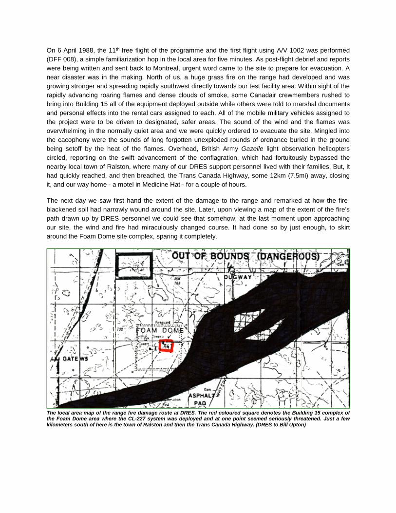
On 6 April 1988, the 11th free flight of the programme and the first flight using A/V 1002 was performed (DFF 008), a simple familiarization hop in the local area for five minutes. As post-flight debrief and reports were being written and sent back to Montreal, urgent word came to the site to prepare for evacuation. A near disaster was in the making. North of us, a huge grass fire on the range had developed and was growing stronger and spreading rapidly southwest directly towards our test facility area. Within sight of the rapidly advancing roaring flames and dense clouds of smoke, some Canadair crewmembers rushed to bring into Building 15 all of the equipment deployed outside while others were told to marshal documents and personal effects into the rental cars assigned to each. All of the mobile military vehicles assigned to the project were to be driven to designated, safer areas. The sound of the wind and the flames was overwhelming in the normally quiet area and we were quickly ordered to evacuate the site. Mingled into the cacophony were the sounds of long forgotten unexploded rounds of ordnance buried in the ground being setoff by the heat of the flames. Overhead, British Army Gazelle light observation helicopters circled, reporting on the swift advancement of the conflagration, which had fortuitously bypassed the nearby local town of Ralston, where many of our DRES support personnel lived with their families. But, it had quickly reached, and then breached, the Trans Canada Highway, some 12km (7.5mi) away, closing it, and our way home - a motel in Medicine Hat - for a couple of hours. The next day we saw first hand the extent of the damage to the range and remarked at how the fire-blackened soil had narrowly wound around the site. Later, upon viewing a map of the extent of the fire’s path drawn up by DRES personnel we could see that somehow, at the last moment upon approaching our site, the wind and fire had miraculously changed course. It had done so by just enough, to skirt around the Foam Dome site complex, sparing it completely.
The local area map of the range fire damage route at DRES. The red coloured square denotes the Building 15 complex of the Foam Dome area where the CL-227 system was deployed and at one point seemed seriously threatened. Just a few kilometers south of here is the town of Ralston and then the Trans Canada Highway. (DRES to Bill Upton)

The massive range fire approaches on a heading straight to the test site complex as equipment is being cleared to safety. The next day, a view from a tower shows just how close the fire had carved its path near the site. The re-deployed A/V 1003 on the TOP is at upper left, while the GCS, power generator and the Vega antenna trailer are at right. (Bill Upton Photos) Just one week later it was time for the jokingly termed ‘Lucky 13’ flight (DFF 010) and here is how events for the superstitious minded turned out. On 13 April 1988, on the 13th free flight of the Phase III series, A/V 1003 took off at 1300hr in wind speeds of 13 knots (24km/h / 15mph). At that moment “Sweaty Betty” (note there are 13 characters in the name) suddenly tilted, yawed, then toppled over and came to rest next to the TOP in this, the first incident in the Phase III programme. The first photograph taken by the author to document the crashed air vehicle and scene was on film frame No. 13. For this 13-member CL-227 flight test and support crew at DRES there would be no “happy snaps” taken. Was the number ‘13’ a viable superstitious (note the 13 letters in ‘superstitious’) one in this event? Nawww!! Oh, and note that the next incident occurred to A/V 1002 when it crashed following a hard landing during flight DFF 013. Hmmm!!! But all was not doom and gloom as some progress and success had been made. In the previous DRES flight with A/V 1002, a range of 10km (6.2mi) from the GCS had been successfully demonstrated and prior to that a height of 950m (3,117ft) was achieved. Semi-automatic and Height mode launches and landings were performed and perfected, greatly easing the tasks of the A/V Operators and qualms of other test team members, thereby soon relegating the troublesome Air Vehicle Collective mode control to basically a standby system. The most heavyweight flight to date with a vehicle mass of 170kg (375lbs) was also easily accomplished halfway through these trials during DFF 007 on 31 March 1988.
During this oftentimes-hectic CL-227 flight test programme, in a bid to maintain good morale and to instill a sense of pride in their work on this programme, test team members Bill Upton and Mark Roe came up with a stylish CL-227 Sentinel Flight Test Team crest. Designed over many drinks in a Medicine Hat motel room and later produced by a Montreal company, these patches were distributed and worn with distinction on hats and/or jackets by all crewmembers for all subsequent CL-227 off-site assignments. These popular items were soon to be in heavy demand by many other test agencies supporting these and ensuing flight-test trials of the CL-227 around North America.
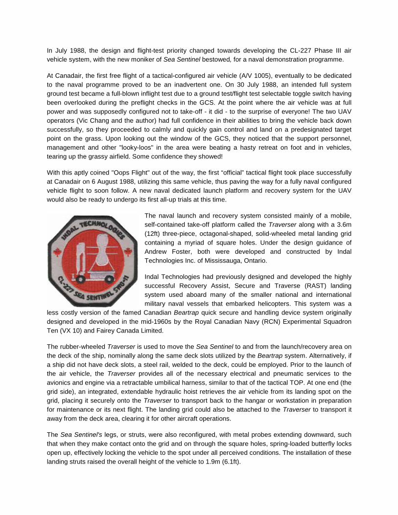
In July 1988, the design and flight-test priority changed towards developing the CL-227 Phase III air vehicle system, with the new moniker of Sea Sentinel bestowed, for a naval demonstration programme. At Canadair, the first free flight of a tactical-configured air vehicle (A/V 1005), eventually to be dedicated to the naval programme proved to be an inadvertent one. On 30 July 1988, an intended full system ground test became a full-blown inflight test due to a ground test/flight test selectable toggle switch having been overlooked during the preflight checks in the GCS. At the point where the air vehicle was at full power and was supposedly configured not to take-off - it did - to the surprise of everyone! The two UAV operators (Vic Chang and the author) had full confidence in their abilities to bring the vehicle back down successfully, so they proceeded to calmly and quickly gain control and land on a predesignated target point on the grass. Upon looking out the window of the GCS, they noticed that the support personnel, management and other "looky-loos" in the area were beating a hasty retreat on foot and in vehicles, tearing up the grassy airfield. Some confidence they showed! With this aptly coined "Oops Flight" out of the way, the first “official” tactical flight took place successfully at Canadair on 6 August 1988, utilizing this same vehicle, thus paving the way for a fully naval configured vehicle flight to soon follow. A new naval dedicated launch platform and recovery system for the UAV would also be ready to undergo its first all-up trials at this time.
The naval launch and recovery system consisted mainly of a mobile, self-contained take-off platform called the Traverser along with a 3.6m (12ft) three-piece, octagonal-shaped, solid-wheeled metal landing grid containing a myriad of square holes. Under the design guidance of Andrew Foster, both were developed and constructed by Indal Technologies Inc. of Mississauga, Ontario. Indal Technologies had previously designed and developed the highly successful Recovery Assist, Secure and Traverse (RAST) landing system used aboard many of the smaller national and international military naval vessels that embarked helicopters. This system was a
less costly version of the famed Canadian Beartrap quick secure and handling device system originally designed and developed in the mid-1960s by the Royal Canadian Navy (RCN) Experimental Squadron Ten (VX 10) and Fairey Canada Limited. The rubber-wheeled Traverser is used to move the Sea Sentinel to and from the launch/recovery area on the deck of the ship, nominally along the same deck slots utilized by the Beartrap system. Alternatively, if a ship did not have deck slots, a steel rail, welded to the deck, could be employed. Prior to the launch of the air vehicle, the Traverser provides all of the necessary electrical and pneumatic services to the avionics and engine via a retractable umbilical harness, similar to that of the tactical TOP. At one end (the grid side), an integrated, extendable hydraulic hoist retrieves the air vehicle from its landing spot on the grid, placing it securely onto the Traverser to transport back to the hangar or workstation in preparation for maintenance or its next flight. The landing grid could also be attached to the Traverser to transport it away from the deck area, clearing it for other aircraft operations. The Sea Sentinel's legs, or struts, were also reconfigured, with metal probes extending downward, such that when they make contact onto the grid and on through the square holes, spring-loaded butterfly locks open up, effectively locking the vehicle to the spot under all perceived conditions. The installation of these landing struts raised the overall height of the vehicle to 1.9m (6.1ft).

This drop test rig was developed, in April 1988, to verify the function and integrity of the new naval configured landing struts when dropped onto a representative landing grid from varying heights and tilt angles. In the left photo, some of the small, spring-loaded butterfly locks are seen opened, but they would normally lie vertically flush within the pointed metal probes. The upper metal structure was simply a system employed to vary the mass and C-of-G of this test article. A/V 1006 was the first fully configured naval air vehicle completed and a series of tether flights were conducted at the Canadair test facilities during July and August 1988. These series of shakedown flights were used to verify that all of the new shipboard software, systems, and interfaces with the new launch/recovery equipment were ready for a free flight. Three Williams engines, newly reconditioned for maritime use, also had their premiere shakedown runs with this air vehicle during this period of time.
On 11 August 1988, the first dedicated free flight of the fully naval configured Sea Sentinel system was conducted with A/V 1006, from a former Compass Rose location near Canadair’s Plant 1 facility, reasonably mocked-up to resemble the parameters of a ship’s deck installation. At left, A/V 1006 rests atop the Traverser during the pre-flight checkout with its umbilical connected and an avionics cooling fan attached around the Control Module’s Avionics Deck area. Then, the vehicle is seen descending vertically to the grid for the first time naval landing. A combined NATO and Canadian Forces technical evaluation team witnessed the event and was suitably impressed with the demonstration. In September 1988, the US Department of Defense (DoD) and Canada's Department of National Defense (DND) signed a Memorandum of Understanding covering a joint US/Canadian evaluation of the CL-227 system. At the same time, Canadair signed another Memorandum of Understanding with AEG of West Germany aimed at exploring the integration of the CL-227 Sea Sentinel into the West German Navy.
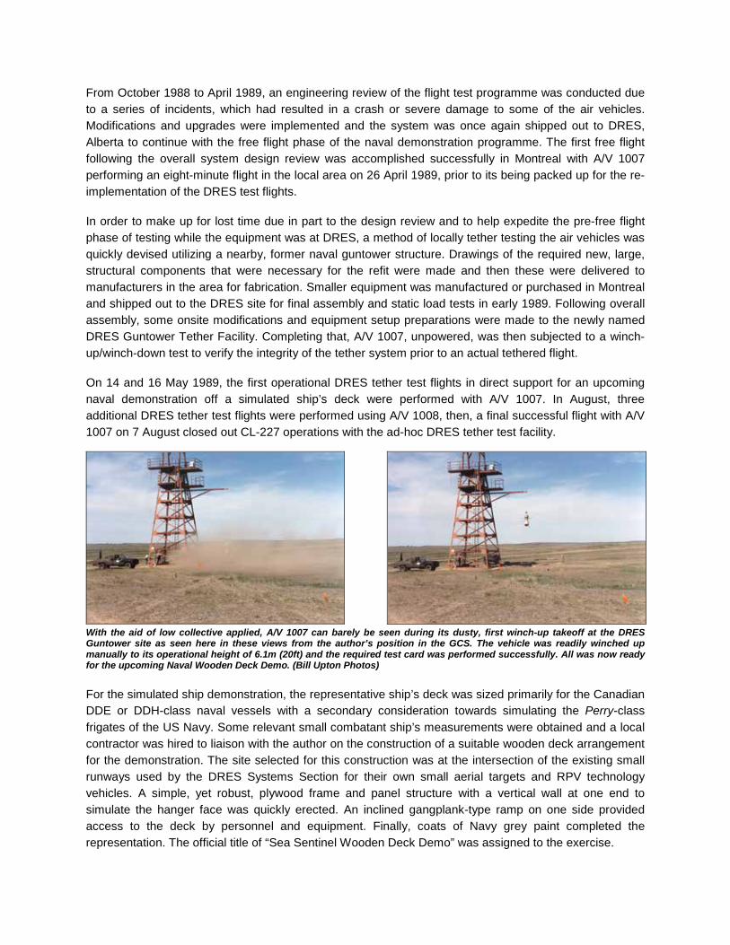
From October 1988 to April 1989, an engineering review of the flight test programme was conducted due to a series of incidents, which had resulted in a crash or severe damage to some of the air vehicles. Modifications and upgrades were implemented and the system was once again shipped out to DRES, Alberta to continue with the free flight phase of the naval demonstration programme. The first free flight following the overall system design review was accomplished successfully in Montreal with A/V 1007 performing an eight-minute flight in the local area on 26 April 1989, prior to its being packed up for the re-implementation of the DRES test flights. In order to make up for lost time due in part to the design review and to help expedite the pre-free flight phase of testing while the equipment was at DRES, a method of locally tether testing the air vehicles was quickly devised utilizing a nearby, former naval guntower structure. Drawings of the required new, large, structural components that were necessary for the refit were made and then these were delivered to manufacturers in the area for fabrication. Smaller equipment was manufactured or purchased in Montreal and shipped out to the DRES site for final assembly and static load tests in early 1989. Following overall assembly, some onsite modifications and equipment setup preparations were made to the newly named DRES Guntower Tether Facility. Completing that, A/V 1007, unpowered, was then subjected to a winch-up/winch-down test to verify the integrity of the tether system prior to an actual tethered flight. On 14 and 16 May 1989, the first operational DRES tether test flights in direct support for an upcoming naval demonstration off a simulated ship’s deck were performed with A/V 1007. In August, three additional DRES tether test flights were performed using A/V 1008, then, a final successful flight with A/V 1007 on 7 August closed out CL-227 operations with the ad-hoc DRES tether test facility.
With the aid of low collective applied, A/V 1007 can barely be seen during its dusty, first winch-up takeoff at the DRES Guntower site as seen here in these views from the author’s position in the GCS. The vehicle was readily winched up manually to its operational height of 6.1m (20ft) and the required test card was performed successfully. All was now ready for the upcoming Naval Wooden Deck Demo. (Bill Upton Photos) For the simulated ship demonstration, the representative ship’s deck was sized primarily for the Canadian DDE or DDH-class naval vessels with a secondary consideration towards simulating the Perry-class frigates of the US Navy. Some relevant small combatant ship’s measurements were obtained and a local contractor was hired to liaison with the author on the construction of a suitable wooden deck arrangement for the demonstration. The site selected for this construction was at the intersection of the existing small runways used by the DRES Systems Section for their own small aerial targets and RPV technology vehicles. A simple, yet robust, plywood frame and panel structure with a vertical wall at one end to simulate the hanger face was quickly erected. An inclined gangplank-type ramp on one side provided access to the deck by personnel and equipment. Finally, coats of Navy grey paint completed the representation. The official title of “Sea Sentinel Wooden Deck Demo” was assigned to the exercise.

The naval configured air vehicle and system were deployed onto the specially constructed platform that accurately resembled the deck of a small combat ship situated adjacent to the existing test site. The wooden deck ‘ship’ was informally dubbed and annotated “HMCS Peanut”. A tall vertical wall had been erected to resemble the face of the ship’s hanger, fortuitously this was removed as a possible safety of flight concern prior to the free flight rehearsal and is seen lying on the ground between the platform and the TLV. In case of difficulties in landing the Sea Sentinel back on the platform, a reversionary landing area was selected on the ground at the near side of the structure. Two flights were conducted from the representative ship’s deck in May 1989 simulating actual surveillance and target spotting capabilities along a pre-planned route. The route, crossing a series of roads and firebreaks, had a series of five numbered plywood markers laid out as targets on a NNE heading. The main target to identify was a derelict army tank located beyond the fifth marker at a range of 1.6 km (2.6 miles). The first flight, designated DFF 014, was a full dress rehearsal with A/V 1007 conducted on 25 May 1989. A sudden, unpredicted high wind gust at the moment of launch resulted in a high tilt angle of the vehicle as it was clearing the Traverser. If the representative hanger wall had still been in place, the mission would possibly have resulted in the vehicle crashing directly into it. This was not the end to problems this day. A difficulty soon arose with the automatic height control system. Erratic Z-Velocity readings implied that there was a serious problem with the Barometric Altitude Reference Unit (BARU) and all vehicle status info was therefore displayed incorrectly to the operators. The A/V kept climbing rapidly despite all efforts with the Land Command switch being set alternatively to On/Off. The A/V Operator usually has full flight control during a mission, however in this case he had his hands full maintaining a steady position via the air vehicle’s video camera image. Therefore, the author, who was the Image Interpreter, switched to the manual Collective Control mode and carefully maintained control of the height of the vehicle during the landing attempt. All the while, due to the unreliable information coming from the vehicle’s avionics, the outside observers called out the vehicle’s position and status to the operators during the long, slow descent. Finally the air vehicle ended its erratic flight and was softly landed perfectly straight into the dirt, at the planned reversionary landing area not far from the GCS.

Little did they know that those genuine pre-flight smiles would be so short lived! The GCS crew consisted of F-R: Dave Roe (RPV Operator), Bill Upton (Image Interpreter), Mark Adcock (Test Conductor) and Andrew Sakamoto (Telemetry). (Bill Upton Photo)
A sudden wind gust blows the vehicle hard towards the simulated ship’s hanger wall area at takeoff for the rehearsal for the Wooden Deck Demo. If the wall had remained there, the flight would have started as a disaster. (Bill Upton Photo)
This is absolutely NOT where a naval configured Sentinel air vehicle is supposed to land. The four landing struts’ probes now had to be carefully disassembled and meticulously cleaned out prior to the next flight. DRES flight DFF 014 was unofficially dubbed “The Hellride” by the worn out test crew, seen mustering smiles of relief for the camera. L-R: Claude Beaudet, Kevin McCarthy, Andrew Leeming, Mark Roe, Bill Upton, Mark Adcock, Andrew Sakamoto, Dave Roe.
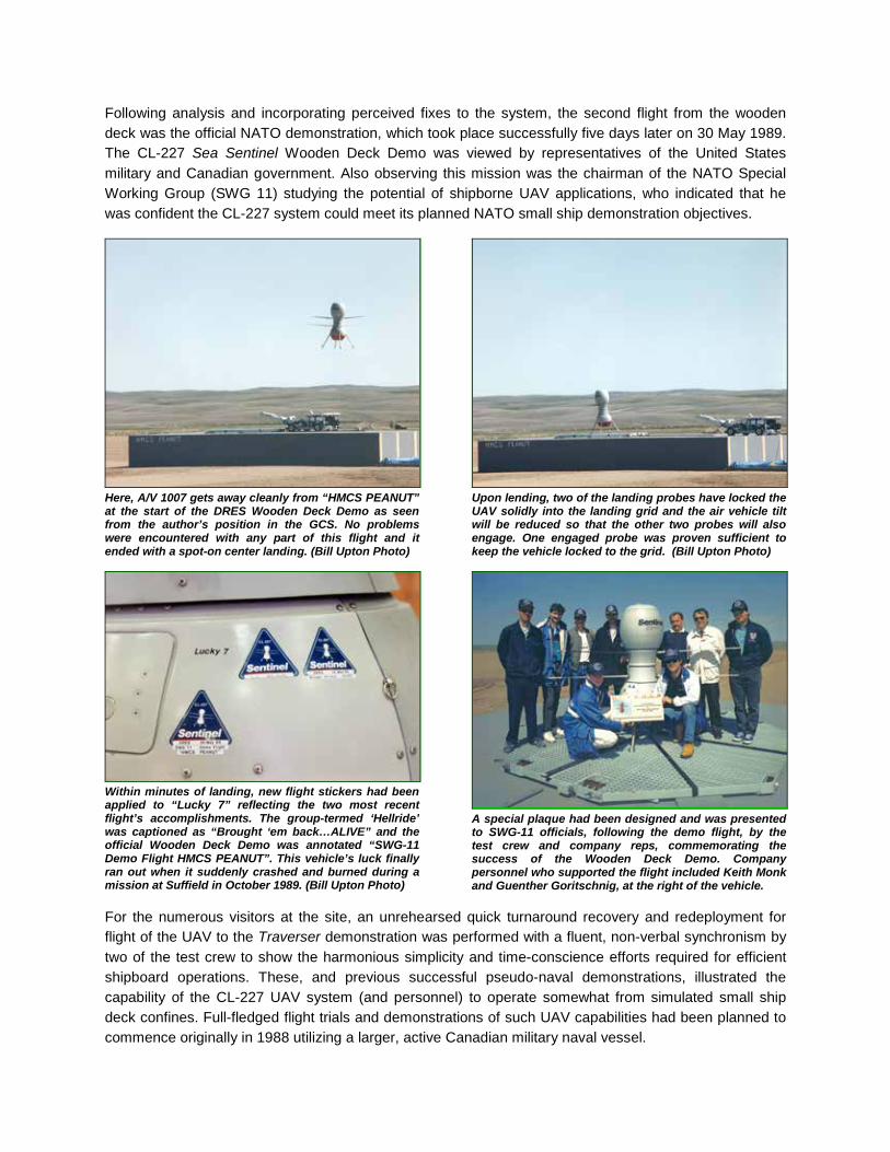
Following analysis and incorporating perceived fixes to the system, the second flight from the wooden deck was the official NATO demonstration, which took place successfully five days later on 30 May 1989. The CL-227 Sea Sentinel Wooden Deck Demo was viewed by representatives of the United States military and Canadian government. Also observing this mission was the chairman of the NATO Special Working Group (SWG 11) studying the potential of shipborne UAV applications, who indicated that he was confident the CL-227 system could meet its planned NATO small ship demonstration objectives.
Here, A/V 1007 gets away cleanly from “HMCS PEANUT” at the start of the DRES Wooden Deck Demo as seen from the author’s position in the GCS. No problems were encountered with any part of this flight and it ended with a spot-on center landing. (Bill Upton Photo)
Upon lending, two of the landing probes have locked the UAV solidly into the landing grid and the air vehicle tilt will be reduced so that the other two probes will also engage. One engaged probe was proven sufficient to keep the vehicle locked to the grid. (Bill Upton Photo)
Within minutes of landing, new flight stickers had been applied to “Lucky 7” reflecting the two most recent flight’s accomplishments. The group-termed ‘Hellride’ was captioned as “Brought ‘em back…ALIVE” and the official Wooden Deck Demo was annotated “SWG-11 Demo Flight HMCS PEANUT”. This vehicle’s luck finally ran out when it suddenly crashed and burned during a mission at Suffield in October 1989. (Bill Upton Photo)
A special plaque had been designed and was presented to SWG-11 officials, following the demo flight, by the test crew and company reps, commemorating the success of the Wooden Deck Demo. Company personnel who supported the flight included Keith Monk and Guenther Goritschnig, at the right of the vehicle.
For the numerous visitors at the site, an unrehearsed quick turnaround recovery and redeployment for flight of the UAV to the Traverser demonstration was performed with a fluent, non-verbal synchronism by two of the test crew to show the harmonious simplicity and time-conscience efforts required for efficient shipboard operations. These, and previous successful pseudo-naval demonstrations, illustrated the capability of the CL-227 UAV system (and personnel) to operate somewhat from simulated small ship deck confines. Full-fledged flight trials and demonstrations of such UAV capabilities had been planned to commence originally in 1988 utilizing a larger, active Canadian military naval vessel.

It seemed that a Canadian DDH-type helicopter-carrying destroyer was to be the first ship to actively employ the CL-227 in its first at-sea trials. At least, that was the plan. In anticipation of this exercise, a small team of CL-227 engineers, including Dave Roe and Derek Baker embarked on a fact-finding voyage onboard HMCS Athabaskan (DDH 282) underway in the Atlantic in an effort to gather information on the feasibility of deploying the CL-227 system on a Canadian frigate or destroyer. During the trip, the ship managed to sneak up on a Soviet Alpha-class submarine and the space tracking ship Yuri Gagarin.
HMCS Assiniboine (DDH 234) was the ship actually selected for primary shipboard NATO SWG-11 flight trials that were to be conducted off the coast of Halifax, Nova Scotia. Some public relations press releases were released highlighting that a Canadian designed and built UAV would soon be flying from a Canadian naval vessel. Unfortunately, due to an untimely spate of air vehicle incidents, this naval deployment was significantly delayed. By the time the revamped air vehicles were once again ready to resume flight evaluation trials, the Assiniboine had been decommissioned (i.e.:paid off) in December 1988 and was eventually sold for scrap. A replacement ship from the Canadian Navy could not be spared for such UAV flight trials at this time and a
scramble was made by the CL-227 engineering group to find another suitable vessel in the interim.
After a thorough fact finding evaluation by senior members of the CL-227 Design and Test Group down in Guatemala, a ship was eventually selected for use. Chosen was a former Tidewater Inc. oil rig replenishment ship - now the Westinghouse-owned M/V Jan Tide, bailed to the US Army - based out of the US Naval Construction Battalion Center, known famously as the “Seabees” at Port Hueneme, California. Measurements and details of the ship deemed it suitable to support all hardware necessary for CL-227 flight trials. Drawings were quickly prepared detailing equipment tie-down locations, and associated components to be manufactured and installed along with some ship’s deck modifications detailed prior to the deployment. Shipboard preparations for acceptance of the Sea Sentinel system began on 15 August 1989. An advance team of the author and electrical engineer Ben Grass arrived to oversee the modifications to the ship’s flight deck, verify area logistic supplies, and aid in the installation of the varied CL-227 support equipment onto the small Tidewater-owned, US Army-leased vessel.
As part of planned exercises to be conducted, the US Army requested demonstrations of the system's target spotting capabilities, which could be used in support of such missions as drug interdiction. This would require the UAV to take off and land from the ship and be vectored to a target boat with range and bearing supplied by an airborne AN/APG-66 radar carried in a large, blimp-like balloon, tethered to the ship. This balloon is known as the Westinghouse Small
Aerostat Surveillance System (SASS). This state-of-the art aerostat configuration was available as a transportable land-based or sea-based airborne detection system capable of detecting targets out to 148km (80nm) and can provide coverage up to 38,847sq.km (15,000sq.mi). Boats with a radar cross section of less than 10m² (108ft²) can be discerned in low sea states out to a distance of 74km (40nm).
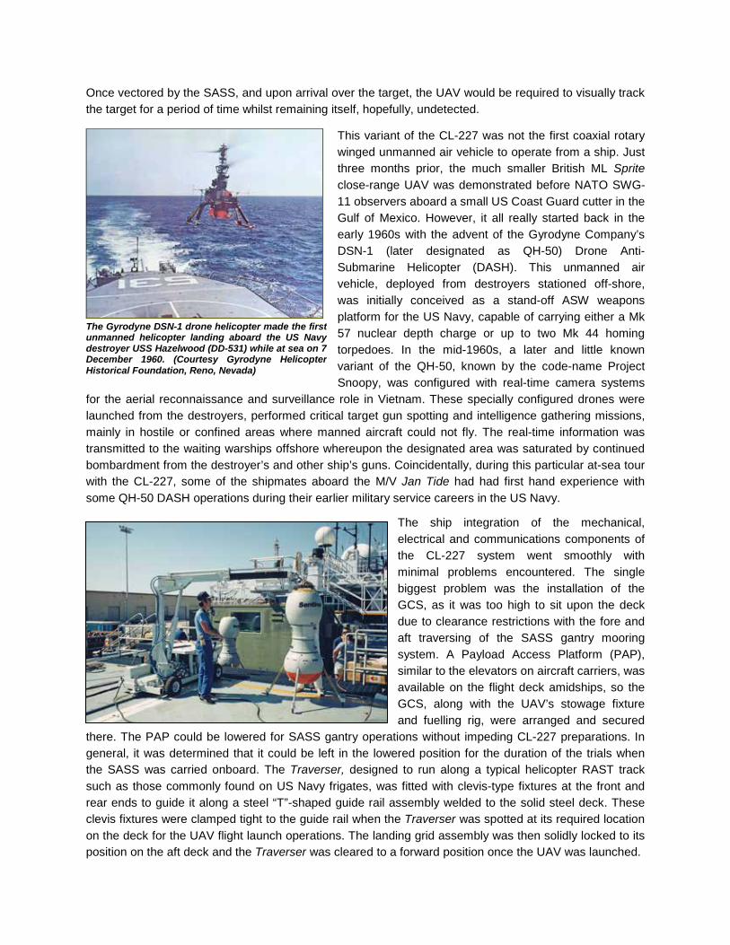
Once vectored by the SASS, and upon arrival over the target, the UAV would be required to visually track the target for a period of time whilst remaining itself, hopefully, undetected.
This variant of the CL-227 was not the first coaxial rotary winged unmanned air vehicle to operate from a ship. Just three months prior, the much smaller British ML Sprite close-range UAV was demonstrated before NATO SWG-11 observers aboard a small US Coast Guard cutter in the Gulf of Mexico. However, it all really started back in the early 1960s with the advent of the Gyrodyne Company’s DSN-1 (later designated as QH-50) Drone Anti-Submarine Helicopter (DASH). This unmanned air vehicle, deployed from destroyers stationed off-shore, was initially conceived as a stand-off ASW weapons platform for the US Navy, capable of carrying either a Mk 57 nuclear depth charge or up to two Mk 44 homing torpedoes. In the mid-1960s, a later and little known variant of the QH-50, known by the code-name Project Snoopy, was configured with real-time camera systems
for the aerial reconnaissance and surveillance role in Vietnam. These specially configured drones were launched from the destroyers, performed critical target gun spotting and intelligence gathering missions, mainly in hostile or confined areas where manned aircraft could not fly. The real-time information was transmitted to the waiting warships offshore whereupon the designated area was saturated by continued bombardment from the destroyer’s and other ship’s guns. Coincidentally, during this particular at-sea tour with the CL-227, some of the shipmates aboard the M/V Jan Tide had had first hand experience with some QH-50 DASH operations during their earlier military service careers in the US Navy.
The ship integration of the mechanical, electrical and communications components of the CL-227 system went smoothly with minimal problems encountered. The single biggest problem was the installation of the GCS, as it was too high to sit upon the deck due to clearance restrictions with the fore and aft traversing of the SASS gantry mooring system. A Payload Access Platform (PAP), similar to the elevators on aircraft carriers, was available on the flight deck amidships, so the GCS, along with the UAV’s stowage fixture and fuelling rig, were arranged and secured
there. The PAP could be lowered for SASS gantry operations without impeding CL-227 preparations. In general, it was determined that it could be left in the lowered position for the duration of the trials when the SASS was carried onboard. The Traverser, designed to run along a typical helicopter RAST track such as those commonly found on US Navy frigates, was fitted with clevis-type fixtures at the front and rear ends to guide it along a steel “T”-shaped guide rail assembly welded to the solid steel deck. These clevis fixtures were clamped tight to the guide rail when the Traverser was spotted at its required location on the deck for the UAV flight launch operations. The landing grid assembly was then solidly locked to its position on the aft deck and the Traverser was cleared to a forward position once the UAV was launched.
The Gyrodyne DSN-1 drone helicopter made the first unmanned helicopter landing aboard the US Navy destroyer USS Hazelwood (DD-531) while at sea on 7 December 1960. (Courtesy Gyrodyne Helicopter Historical Foundation, Reno, Nevada)

The M/V Jan Tide, skippered by the First Officer, leaves its home port, with CL-227 “MX” deployed on the small flight deck, for a shakedown cruise to verify equipment installations and preliminary operational tasks (without flight crew queasiness) off the California coast. The first true naval flight of the CL-227 Sea Sentinel took place later that afternoon. Until full systems’ operational procedures were finalized, the SASS was not carried on the first few at-sea trials. (Bill Upton Photo)
The first at-sea flight of the CL-227 was conducted on 24 August 1989, within a specific operational test range area made available by the Pacific Missile Test Center (PMTC) at Point Mugu, California. The eight and a half-minute flight went perfectly. The principal allocated section of the tightly controlled PMTC test range was located some 11.1km (6nm) from homeport at Port Hueneme, with sides of 43km (23nm) by 22.2km (12nm). Due to some flight safety restrictions, this area was later reduced to 18.5 by 11.1km (10nm by 6nm). An adjacent section was made available for later, longer flights. Nearby was the Channel Islands
National Park with the three islets of Anacapa Island being featured in some of the transit to the test range photographs. Truly, this was to become one of the trickiest series of flight demonstrations in the history of the CL-227 programme to this time. Critical planning was necessary for these trials, as only a five-week period of time was made available due to other scheduled duty commitments of the Jan Tide. Prior to this deployment, A/V 1010 had performed a series of tether and three Navy Safety Demo-titled free flights back at the Canadair facilities to verify all systems were indeed ready for this challenging, new assignment. Basically the same as the land-based variant, this naval version was further modified to reduce the effects of EMI. Also, for the naval applicable free flights, a new and somewhat whimsical free flight sticker was adopted depicting a wide-eyed cartoon CL-227 UAV with swim fins, a snorkel and mask. This was applied to the vehicle’s Control Module skin after the successful completion of a naval supported flight in lieu of the blue triangular stickers previously used.

On the voyage to the assigned test area, the Canadian crew noticed similarities in scenery to some parts of Canada’s East Coast. This view here, transiting through the Channel Islands National Park, is actually of Anacapa Island with its prominent Arch Rock the most notable natural feature of the eastern side of the islet. (Bill Upton Photo)
While underway to the PMTC test area, the Roe brothers, Dave and Mark, prepare A/V 1010 for the second free flight from the deck of the Jan Tide. Dave hands Mark a rotor blade to install on the vehicle and when that task is completed they both leave the deck area to take their positions. (Bill Upton and Paul Sagala Photos) The first phase of flights from the Jan Tide were scheduled without the SASS balloon onboard. These were basically to verify the CL-227 system integration with the ship’s systems and to train the ship’s crew and Canadair team in this new sea-based flight operations environment in preparation for a planned demonstration for the NATO Special Working Group (SWG-11). The typical flight profile had the UAV in a hover 200m (656ft) astern following takeoff where control and telemetry checks were performed. Then, the vehicle was flown parallel to and at right angels to the ship while climbing to the required height. Upon completion of these operational and control tasks the vehicle was positioned to intercept the ship’s wake at a height of 500m (1,640ft), then using the wake as a guide, the approach and landing were performed to the landing grid on the deck.
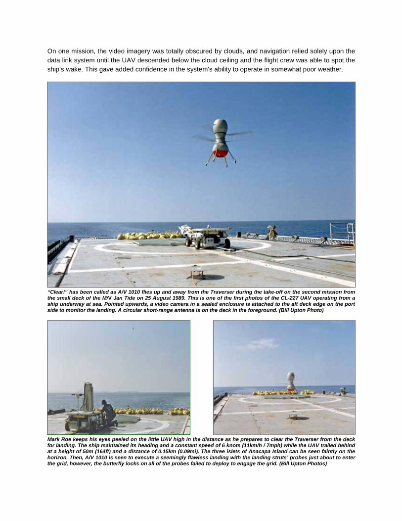
On one mission, the video imagery was totally obscured by clouds, and navigation relied solely upon the data link system until the UAV descended below the cloud ceiling and the flight crew was able to spot the ship’s wake. This gave added confidence in the system's ability to operate in somewhat poor weather.
“Clear!” has been called as A/V 1010 flies up and away from the Traverser during the take-off on the second mission from the small deck of the M/V Jan Tide on 25 August 1989. This is one of the first photos of the CL-227 UAV operating from a ship underway at sea. Pointed upwards, a video camera in a sealed enclosure is attached to the aft deck edge on the port side to monitor the landing. A circular short-range antenna is on the deck in the foreground. (Bill Upton Photo)
Mark Roe keeps his eyes peeled on the little UAV high in the distance as he prepares to clear the Traverser from the deck for landing. The ship maintained its heading and a constant speed of 6 knots (11km/h / 7mph) while the UAV trailed behind at a height of 50m (164ft) and a distance of 0.15km (0.09mi). The three islets of Anacapa Island can be seen faintly on the horizon. Then, A/V 1010 is seen to execute a seemingly flawless landing with the landing struts’ probes just about to enter the grid, however, the butterfly locks on all of the probes failed to deploy to engage the grid. (Bill Upton Photos)

In total, nine successful missions in two separate phases were flown by “MX” from the Jan Tide, including one flight on 30 August for representatives of the NATO SWG-11, which included observers from Canada, the United States, the Netherlands, the United Kingdom, and West Germany. These visitors were accommodated in three observer boats positioned in line abreast approximately 92m (300ft) to starboard of the Jan Tide. The Jan Tide and boat entourage plowed along in Sea State 3-4 conditions with ship roll angles exceeding 5 degrees, but this did not prove an impediment to the UAV operations. The planned flight profile had the Sea Sentinel fly out to 6km (9.7mi), but due to downlink problems this was shortened to 500m (1,640ft). The approach and intended wave-off followed by a successful landing to the grid fulfilled the requirements of the demonstration. Another demo for the US Army Unmanned Aerial Vehicle Joint Programme Office (JPO) in conjunction with various military and industry observers was performed on 16 September in conjunction with the SASS during the second phase of this exercise. A similar setup of observer boats as was arranged for the NATO Demo was coordinated. A range of 6.9km (4.3mi) was achieved and target images from the airborne UAV were viewed for the first time in real-time by the observers on this, the last flight of the CL-227 Sea Sentinel from the M/V Jan Tide.
On an earlier proving flight in the second phase, also with the SASS balloon deployed, the UAV was vectored by the SASS radar to two 27.4m (90ft) long powerboats simulating a drug run with evasive actions by these boats being planned into the exercise. A trained observer and photographer on one of the target vessels never spotted the CL-227 hovering quietly about 700m (2,297ft) above, even when he was told where to look. In contrast the Sea Sentinel tracked and recorded every action of both maneuvering targeted boats over roughly a ten minute period, transmitting this information back to the GCS and the command and control center onboard the Jan Tide. The subsequent flight on 14
September achieved a CL-227 UAV ground speed of 27 knots (50km/h / 31mph) on the outward leg by commanding a UAV tilt of 14 degrees, demonstrated to satisfy part of a contractual requirement.
Prior to the start of the joint SASS / CL-227 flights the SWG-11 representatives and other visitors paid a visit to the Jan Tide. Here A/V 1008 is seen displayed on the Traverser and A/V 1010 is centered on the grid.
The SASS is fully inflated and being prepared for the Phase 2 series of flight trials. Here it is on the SASS gantry at the full aft-stowed position on the Jan Tide. A CL-227 is also seen deployed aft on the Traverser.
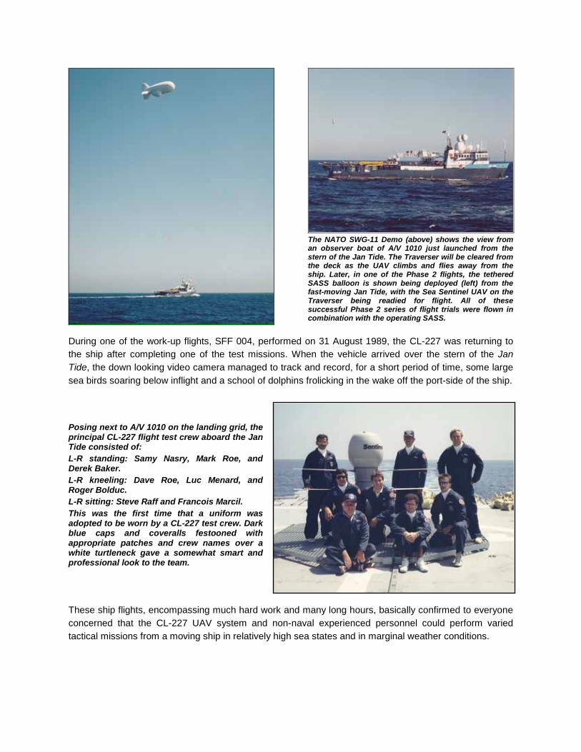
The NATO SWG-11 Demo (above) shows the view from an observer boat of A/V 1010 just launched from the stern of the Jan Tide. The Traverser will be cleared from the deck as the UAV climbs and flies away from the ship. Later, in one of the Phase 2 flights, the tethered SASS balloon is shown being deployed (left) from the fast-moving Jan Tide, with the Sea Sentinel UAV on the Traverser being readied for flight. All of these successful Phase 2 series of flight trials were flown in combination with the operating SASS.
During one of the work-up flights, SFF 004, performed on 31 August 1989, the CL-227 was returning to the ship after completing one of the test missions. When the vehicle arrived over the stern of the Jan Tide, the down looking video camera managed to track and record, for a short period of time, some large sea birds soaring below inflight and a school of dolphins frolicking in the wake off the port-side of the ship. Posing next to A/V 1010 on the landing grid, the principal CL-227 flight test crew aboard the Jan Tide consisted of: L-R standing: Samy Nasry, Mark Roe, and Derek Baker. L-R kneeling: Dave Roe, Luc Menard, and Roger Bolduc. L-R sitting: Steve Raff and Francois Marcil. This was the first time that a uniform was adopted to be worn by a CL-227 test crew. Dark blue caps and coveralls festooned with appropriate patches and crew names over a white turtleneck gave a somewhat smart and professional look to the team. These ship flights, encompassing much hard work and many long hours, basically confirmed to everyone concerned that the CL-227 UAV system and non-naval experienced personnel could perform varied tactical missions from a moving ship in relatively high sea states and in marginal weather conditions.

Sometimes events occur during trials that can be amusing only upon reflecting back, and can offset the hard work and hours put in by the flight test and support crews. One such event occurred during the ground based support of the trials when Bill Upton with Paul Sagala of the Photographic department were photographing and filming, for the Canadair Marketing and PR departments, the entry sign for the Headquarters Pacific Missile Test Center, located near the front gate. They were composing their shots for several minutes and could see a military
van inside travelling back and forth slowly. It disappeared for a few minutes, then raced back beside them and before they knew it, K-9 guard dogs and the “long arms” of the law, military and civilian surrounded them. They both thought for sure that they were going to be thrown into jail, but fortunately following the intervention of the state trooper, both were allowed to go their own way after being sternly told, "No photographs". What they discovered later talking with the trooper was the rule of the invisible blue line. Apparently, they could have taken all the shots they wanted on one side of a blue strip laid across the entry road they were on. One side of the blue line is government property, the other civilian. But, upon inspection of the designated area, there was no line to be seen, as it had not been painted there as yet! During October 1989, one non-flying air vehicle (hanger queen A/V 1004 with a set of spare skins), along with support crew members Gareth Richardson, Bill Upton, and Mark Roe, were sent to the White Sands Missile Range (WSMR), adjacent to Holloman Air Force Base near Alamogordo, New Mexico. Their assignment was to aid in determining the actual radar cross section (RCS) of the CL-227 Phase III UAV under the auspices of the Radar Target Scatter (RATSCAT) facility. The RATSCAT facility was originally conceived to provide precision signature measurements of low observable weapon systems for the military. Civilian and US military personnel were to perform the actual tasks with our support of the UAV.
The vast endless rolling sand dunes of the aptly named White Sands National Monument in New Mexico. (Bill Upton Photo)
The infamous entry gate sign to the Headquarters of the Pacific Missile Test Center at the USNAS Point Mugu in California. (Bill Upton Photo)

The long route to work from our lodgings in nearby Alamogordo to the RATSCAT site, situated in the Tularosa Valley Basin between the San Andres and Sacramento Mountain ranges, took us past some of the ramps and hangars of Holloman Air Force Base. Once past this most interesting area, and through a couple of military checkpoints, a completely new and somewhat foreign landscape was laid out before us on a long and winding two-lane road leading to a tiny part of the vast White Sands Missile Range. The name “White Sands” is somewhat of a misnomer as the area is actually composed of bright, white gypsum, but not sand. Along each side of the quiet road were seemingly endless dunes of this white gypsum. Some of the windswept material had been deposited and much had drifted across the lonely road. Driving through this white scenery and with the air conditioning of the car at full blast, one might assume this to be a scenic Winterscape. The gypsum drifts across the road were definitely not to be mistaken for powered snow, as that drifted material was very dense and could easily flip over a car (and apparently had) attempting to plow through or over it. A particular stretch of this route and a singular small pond area were seen from the air during the title sequence of the 1978 Hollywood movie “Convoy”.
Oftentimes the gypsum drifts across the access road and some brave souls attempt to plow through them in their vehicles, as seen in the photo at left. At right, a small, cool looking, and seemingly refreshing turquoise pond, was seen in the movie “Convoy”. On close inspection all animal tracks skirt the pond and no insect or any other life forms could be detected in its clear depths. Apparently, at this lonely oasis, these inviting waters were very poisonous. (Bill Upton Photos)
A preliminary series of static tests was performed with the air vehicle on a tall polystyrene pylon to establish initial baseline data. That was soon followed by a series of Doppler tests that were run, whereby a small pneumatic line was routed from compressed air bottles (cached in an underground enclosure beneath the test arrangement), up to the vehicle and hard connected to the vehicle’s standard air start line. A mechanical valve was opened as necessary to permit the air from the compressed air bottles to windmill the engine at varying speeds, thereby rotating the blades. To avoid any
potential of ‘glow-in-the-dark’ syndrome, all of the test personnel were cleared away to the office and control buildings in a remote area of the White Sands’ range while these tests were being conducted.
Multi-coloured A/V 1004 on its carved pylon is ready for its first series of Doppler tests. In the shallow pit below are compressed air bottles with a regulator valve to vary the rotor speed of the UAV. (Bill Upton Photo)

The tiny orange speck atop the not too much larger white pylon gives a very small perspective of the area at RATSCAT Site #3 at the aptly named White Sands Missile Range. A low sun angle produced a darker hue of gypsum. At right is the Mobile Hanger, a multi-level enclosure that protects and provides site maintenance and handling facilities to a test article. It runs back and forth to the test area on four sets of main gear bogies scavenged from Cold War-era B-47 bombers. According to local lore, there is a fortune in buried treasure lost in the San Andres Mountains beyond. (Bill Upton Photo) Test runs for the RCS studies were conducted at the sites during the day and well into the late night hours for about a month, with the vehicle posed at numerous tilt angles on the polystyrene pylon until all data points were established, ready for detailed analysis. All of the superb support staff of local contractor DynCorp, Radar Backscatter Division, made the logistics of the work involved so much easier for us.
This vast-looking expanse is just a very small part of the RATSCAT test facility, itself a tiny area of the immense White Sands Missile Range. A/V 1004 is mounted atop a shaped polystyrene pylon that, hopefully, has a lower RCS value than the test subject. (Bill Upton Photo)
The Payload Module section was covered in metal foil tape to aid in actually being able to ‘see’ the little UAV for initial baseline data evaluations. Its radar cross section was determined to be far less than the specification originally designed for. (Bill Upton Photo)
Sometimes the monotony of the tests was replaced by excited periods of time when the RATSCAT site and personnel went into “Undercover” due to a missile and drone interception scheduled to take place somewhere overhead. No personnel were permitted anywhere near the area in case of uncontrollable falling pieces of destroyed aircraft rained down nearby. Once in a while from the roadblock area incredibly fast streaks of smoke could be seen in the deep blue sky, but no actual interceptions were witnessed.

The CL-227 wasn’t the only Canadair produced unmanned air vehicle located in the area at this time. On nearby Holloman AFB, the 6585th Test Group maintained a small fleet of aging QF-86E Sabre fighter aircraft on their drone ramp. These Sabres were a mixed bag of Mk 5 and Mk 6 examples, all manufactured by Canadair Limited in the 1950s. Most of the aircraft seen were in natural metal with a da-glo orange fin in standard US Army drone markings, while a couple were configured as target tugs and were
painted in the Flight Systems, Inc. (FSI) house colours and markings. The author and Mark Roe had a supervised ramp tour by some FSI staff and marveled over these old, yet very well kept, machines. One of the venerable Sabre aircraft was seen flying overhead one day with America’s latest fighter, a USAF F-15 Eagle, as its wingman, these being the two foremost fighters of their respective eras.
A Canadair QF-86E Sabre 6 target tug, N82FS (formerly Luftwaffe 1600), in the FSI colours and markings, and a QF-86E Sabre 5 drone, N4688J (ex-RCAF 23209) seen at Holloman AFB. (Bill Upton Photo)
Canadair QF-86E Sabre 5 drone (ex-RCAF serial number 23208) on the dusty Holloman AFB drone ramp, still bears clear, but faded evidence of its former RCAF service markings. (Bill Upton Photo)
During July and August of 1989, a concurrent evaluation of the land-based CL-227 system was being funded and conducted jointly by United States and Canadian military personnel, once again at DRES, in Alberta. A small cadre of personnel from the Canadian Forces Artillery carried out many of these training and evaluation flights in conjunction with supervising Canadair Surveillance Systems’ staff, thus marking the first time that non-Canadair crew members operated with the UAV system during free flight trials. With an increase in take-off mass from 170kg (375lb) to 190kg (419lb) and to permit the carriage of larger payloads and increase performance, a new rotor blade was developed with a radius of 1.4m (the 55-inch blade). This new blade design flew on A/V 1007 at DRES on 28 September 1989. The final CL-227 free flight at DRES occurred on 02 December 1989 with A/V 1008 achieving an altitude of 2,500m (8,200ft).
By early January 1990, this land-based system was readied for deployment to Fort Huachuca, Arizona, to evaluate system performance, reliability, and survivability. This was the next phase of the joint US and Canadian evaluation of the system, being assessed for the short-range portion of the US Army’s Forward Area Air Defense System (FAADS). The Canadian Forces evaluations of the system were to support their Unmanned Airborne Surveillance and Target Acquisition System (UASTAS) project definition. New, off-the-shelf sensor equipment, some similar to that employed previously with Lockheed’s recently
cancelled Aquila battlefield RPV project, was to be evaluated in the CL-227 Payload Module. Principally partnered with Texas Instruments (TI), the CL-227 Sentinel UAV was to employ, for the first time, a tactical lightweight Forward-Looking Infrared (FLIR) sensor package for system evaluation.

The Canadian Forces (CF) Artillery personnel were to participate heavily in these trials including performing mission flight planning, air vehicle preparations, site setup, conducting flights and recovery based upon the training received during the most recent DRES trials. Only two members of the original Canadian military group trained back in Montreal in 1987 remained, with four new recruits joining the team. Following initial flight tests by the experienced Canadair / Bombardier flight test team to confirm system functioning, the cadre of CF personnel performed the subsequent three missions, with logistical support and additional training supplied as necessary by the Montreal-based CL-227 test personnel. On first arrival to the test range, the test team personnel had been made aware, in a welcome and safety briefing by the local authorities, of some of the many hazards that may be encountered in the field, among them poisonous snakes! Apparently some snakes, lizards and other “creepy crawlies” liked to get cozy under covered items left outside during the night. The outdoors equipment setup crew were particularly warned and advised that prior to removing tarps and other equipment coverings, they should perform a kind of cautionary kick-and-jump-back dance to that particular piece of equipment. That way, any potentially harmful creature(s) that may have crawled, slithered or squirmed underneath would be startled enough to leave and the crew could then proceed with their tasks at hand. During the initial field deployment and equipment setup training of the military personnel, it became apparent that, due to some very minor procedural mix-ups during the setup of the air vehicle onto the TOP, some of the warnings were not being heeded. In a bid to see if the directions of the test crew were actually being listened to, a cheap, store-bought rubber snake, coiled and compressed, was strategically placed under the TOP’s tarpaulin cover. That quickly put an end to any further training woes at the site!
Cached amid the tall, dry desert grass and shrubs, as well as a few protected Agave cactus plants, A/V 1008, seemingly just pops-up from the semi-hidden TOP on the first flight (HFF 001) at the Fort Huachuca test range on 09 January 1990. The tarpaulin-covered MAST and an electrical power generator can be seen stationed off at the right. (Bill Upton Photo) The first flight at the vast Fort Huachuca Test Range, from the facilities of the Black Tower complex, was a 115-minute evaluation mission with CF Captain K. Little as the Air Vehicle Operator. The set objectives of this flight were to evaluate the Sentinel’s stability, range, and climb rate transiting along a zigzag route of 19 separate Way Points over the high mountains and deep canyons. An altitude of 2,400 m (7,874 ft) and speeds ranging from a hover to 25 m/sec (83 ft/sec) were readily achieved.

Upon this first landing at the designated cleared area, the air vehicle’s rotor downwash in the hover churned up a significant amount of sand dust. Subsequently, the landing site was lightly watered down prior to all of the landing attempts. (Bill Upton Photo)
The tall, rounded peaks of the Huachuca Mountains form a most spectacular area backdrop, as A/V 1009, controlled for the first time by an all-Canadian Forces crew, heads out from the Black Tower area on 10 January 1990. (Bill Upton Photo)
The “happy snap” of the Canadian Forces Artillery personnel on 11 January 1990, posing with A/V 1008 following the third Fort Huachuca flight. L-R: Corporal Art Snodgrass, Gunner Mark Farrar, Captain K. Little, Captain R. Stones, Master Corporal Don Labbé and Master Warrant Officer Russ Byers. This was the 13th free flight of this vehicle, as witnessed by the blue triangular stickers on the Control Module’s skins. The lower section of the Power Module sports a C-Band antenna, mounted to enable tracking of the vehicle by the local test facility. (Bill Upton Photo) Due to the proximity of Fort Huachuca to the vast and largely unregulated Mexican frontier, it was suggested that possible UAV border patrol missions, in concert with a few locally deployed SASS balloons could be a viable deterrent to smuggling and illegal immigration into the United States. The necessary logistics required (funding, politics, and legalities) to attempt to perform such missions were not anywhere near to being in place at that time, so no such co-operative missions were ever performed.

Prior to some CL-227 flights where any A/V components were exchanged, replaced or software was updated, a standard bladeless run would be performed on the TOP in order to verify proper functions of the new or replaced component(s). Prior to the last flight performed by the full DND crew on 16 January 1990 (HFF 004), a bladeless run was performed in the morning with A/V 1009, seen here about to start with a passing dramatic backdrop. (Bill Upton Photo)
The finale of the CL-227 flight HFF 004 with a successful landing after the weather front had passed by. An additional two standard free flights were conducted with a DND A/V Operator before these troops returned to Canada. (Bill Upton Photo) Also observed in flight tests at Fort Huachuca were examples of the new-ish Pioneer tactical close range UAV. Flying from the Fort Huachuca drone airstrip near the Black Tower site, this medium-sized, fixed-wing vehicle was so readily seen, and heard – very distinctly - during the downtime of the CL-227 trials. We had to stay indoors “Undercover” during most of these flights as did the Pioneer test crew when the CL-227 was flying. Comparatively, all personnel around agreed that the CL-227 UAV was of a magnitude quieter and much stealthier than the Pioneer fixed-wing vehicles during their respective flights around the area. That is all except for one little old lady down in the valley nearby, who, upon seeing our UAV inflight, would immediately telephone the Black Tower office during every single flight. She vehemently warned that there had better not be any lasers firing at her, and to get away from over her farmhouse, or she would shoot at it. She thought that the four landing legs with translucent balled feet reflecting the sunlight were some kind of laser rifles and feared for her life. Dutifully our test hosts kindly addressed each call and her fears were quickly allayed – until the next flight. Happily, no shots were fired that we knew of.

In order to enhance the Sentinel’s inherent stealthiness, flights were performed with an Echosorb radar absorbent material (RAM) skin configured vehicle, as well as evaluations to establish the infrared, acoustic and visual signatures. Without the RAM, it had been previously determined, at RATSCAT that the CL-227 had a recorded RCS of less than 0.1m². The acoustic signature was considered virtually undetectable, even at close range. Photographs were not taken for the record during the singular RAM flight of A/V 1008 at Fort Huachuca. However, it was determined that the vehicle’s inherent stealthiness was satisfactory enough to not warrant the added mass of the Echosorb material to cut into the payload carrying, range or loiter capabilities. Echosorb was an elastomeric type of RAM, tuned to more than one frequency. It was one of the first RAMs applied to the undersides of some Lockheed U-2 spyplanes in 1956, these were colloquially known by their flight and maintenance crews as the “dirty birds”.
The first flight of the Sentinel utilizing the Texas Instruments' STA-360 FLIR imagery sensor payload was conducted at Fort Huachuca on 15 February 1990. This successful flight thereby further enhanced the CL-227 UAV system’s potential for day, low light, or dark of night operations.
A/V 1009 with the Texas Instruments FLIR lifts off from the Traverser cached behind the tall dry grass and Agave cacti that covered the test area. The Agave are protected in this area due to a small endangered bat that feeds off them at night and the test team had to ensue that no harm came to these plants during pre- and post-flight operations. Although FLIR sensors had been ground tested back home, this was the first flight of a CL-227 air vehicle with a FLIR payload installed. In the first 18 days of these intensive Canadian Army training and flight trials, CL-227 Sentinel A/V’s 1008 and 1009 performed eight flights. These combined flights accrued close to 50% of the total flight hours flown in the first 62 free flights of the overall CL-227 Phase III trials programme. The Canadian DND crew performed six of the Fort Huachuca flights in full or in part, with Canadair personnel closely monitoring the instrumentation and flight data during these missions.
Sentinel Air Vehicle 1004 is seen in the Canadair UAV assembly shop in September 1988 with a test fit of some of the Echosorb RAM applied, prior to utilizing and evaluating it on an actual flight test vehicle.

A US Army UH-1H Huey SAR helicopter acts as a pacer and photographic chase platform with Canadair photographer Paul Sagala aboard during the start of A/V 1008’s record 40 km sojourn around and above the varied southern Arizona landscape. During the 93-minute demonstration flight, still photographs and colour video from the helicopter and the air vehicle’s own TV Payload’s black and white imagery recorded this unique opportunity in full detail. (USAEPG for SSD) During these joint evaluation trials, on 24 February 1990, A/V 1008 equipped with a small daylight TV payload, successfully reached a target area more than 40km (24.8mi) from its takeoff point at the Black Tower of the US Army Experimental Proving Grounds (USAEPG). At a maximum altitude reached of 2,500m (8,202ft), the little vehicle breached the nearby Huachuca Mountain range flying over a couple of busy highways. It then quietly passed high above some small towns, no doubt enticing local UFO enthusiasts and conspiracy theorists alike to regale to anyone who would listen to their tales of a grey and orange-coloured flying peanut-shaped object with no wings being “chased” by a US military helicopter!
A/V 1008 starts out over Fort Huachuca with a full head of steam as can be seen by the hazy exhaust plume streaming up and being pulled down into the upper rotor wash at the left side of the vehicle.
The voyage started out over dry, desert terrain but eventually the UAV made its way to the local mountain ranges where the former sparse terrain became one with dense brush and small trees.
The mostly flat, sand-coloured desert landscape seen below the air vehicle could be best described as desperately desolate. The excessively dry conditions of the terrain showed rare evidence of civilization with a couple of large blue water reservoirs supplying the much needed moisture to small nearby towns, some large pockmarked areas of natural vegetation and even a few successful human cultivation efforts.

Steaming outbound, A/V 1008 crests the mountain range soon after leaving the launch site.
Over the flatlands, the UAV passes over a large, isolated water reservoir and cultivated fields.
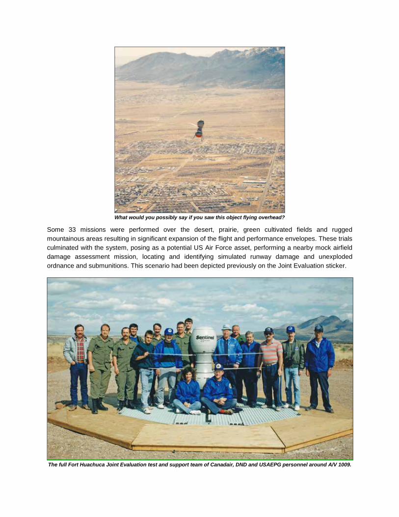
What would you possibly say if you saw this object flying overhead?
Some 33 missions were performed over the desert, prairie, green cultivated fields and rugged mountainous areas resulting in significant expansion of the flight and performance envelopes. These trials culminated with the system, posing as a potential US Air Force asset, performing a nearby mock airfield damage assessment mission, locating and identifying simulated runway damage and unexploded ordnance and submunitions. This scenario had been depicted previously on the Joint Evaluation sticker.
The full Fort Huachuca Joint Evaluation test and support team of Canadair, DND and USAEPG personnel around A/V 1009.
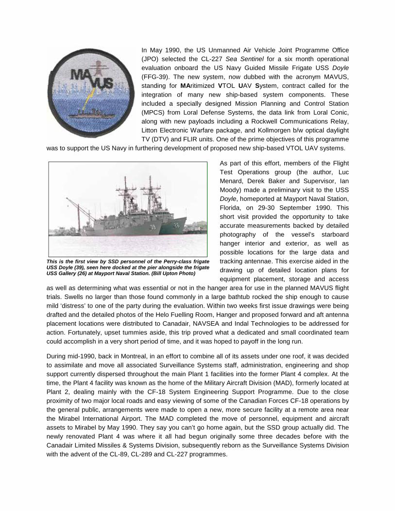
In May 1990, the US Unmanned Air Vehicle Joint Programme Office (JPO) selected the CL-227 Sea Sentinel for a six month operational evaluation onboard the US Navy Guided Missile Frigate USS Doyle (FFG-39). The new system, now dubbed with the acronym MAVUS, standing for MAritimized VTOL UAV System, contract called for the integration of many new ship-based system components. These included a specially designed Mission Planning and Control Station (MPCS) from Loral Defense Systems, the data link from Loral Conic, along with new payloads including a Rockwell Communications Relay, Litton Electronic Warfare package, and Kollmorgen b/w optical daylight TV (DTV) and FLIR units. One of the prime objectives of this programme
was to support the US Navy in furthering development of proposed new ship-based VTOL UAV systems.
As part of this effort, members of the Flight Test Operations group (the author, Luc Menard, Derek Baker and Supervisor, Ian Moody) made a preliminary visit to the USS Doyle, homeported at Mayport Naval Station, Florida, on 29-30 September 1990. This short visit provided the opportunity to take accurate measurements backed by detailed photography of the vessel’s starboard hanger interior and exterior, as well as possible locations for the large data and tracking antennae. This exercise aided in the drawing up of detailed location plans for equipment placement, storage and access
as well as determining what was essential or not in the hanger area for use in the planned MAVUS flight trials. Swells no larger than those found commonly in a large bathtub rocked the ship enough to cause mild ‘distress’ to one of the party during the evaluation. Within two weeks first issue drawings were being drafted and the detailed photos of the Helo Fuelling Room, Hanger and proposed forward and aft antenna placement locations were distributed to Canadair, NAVSEA and Indal Technologies to be addressed for action. Fortunately, upset tummies aside, this trip proved what a dedicated and small coordinated team could accomplish in a very short period of time, and it was hoped to payoff in the long run. During mid-1990, back in Montreal, in an effort to combine all of its assets under one roof, it was decided to assimilate and move all associated Surveillance Systems staff, administration, engineering and shop support currently dispersed throughout the main Plant 1 facilities into the former Plant 4 complex. At the time, the Plant 4 facility was known as the home of the Military Aircraft Division (MAD), formerly located at Plant 2, dealing mainly with the CF-18 System Engineering Support Programme. Due to the close proximity of two major local roads and easy viewing of some of the Canadian Forces CF-18 operations by the general public, arrangements were made to open a new, more secure facility at a remote area near the Mirabel International Airport. The MAD completed the move of personnel, equipment and aircraft assets to Mirabel by May 1990. They say you can’t go home again, but the SSD group actually did. The newly renovated Plant 4 was where it all had begun originally some three decades before with the Canadair Limited Missiles & Systems Division, subsequently reborn as the Surveillance Systems Division with the advent of the CL-89, CL-289 and CL-227 programmes.
This is the first view by SSD personnel of the Perry-class frigate USS Doyle (39), seen here docked at the pier alongside the frigate USS Gallery (26) at Mayport Naval Station. (Bill Upton Photo)

Further flight trials to evaluate technical improvements to the system and to further expand the flight envelope of the CL-227 UAV took place at the Yuma Proving Grounds (YPG) facilities near Yuma, Arizona, at the end of 1990. A series of flights were carried out utilizing different fuels like JP-4 and JP-5 in lieu of the commonly used diesel grades to evaluate how the engine would behave. These tests went well, but the air vehicle mechanic and the Williams engine rep were kept busy cleaning and stripping down the engine to verify no problems were encountered. On-site available vehicles to be used as spotting targets included an array of old, retired US Army and German tanks that were still mobile enough for the trial’s purposes.
A/V 1008 sits at the ready with the white Umbilical Connector connected to the vehicle on the TOP at the Yuma test site preparatory to its first flight from this location. This circular concrete site was a former helicopter pad surrounded by a large loose rock area deemed suitable for the UAV landings. The covered MAST is parked off to the left. (Bill Upton Photo)
Near the CL-227 test site other, older, rotary-winged vehicles showed an interest in the newer one being flown at the YPG. Here an armed US Army Bell AH-1F (at left) and Army Bell UH-1H SAR helicopters visited the remote site during these Sentinel trials. In the photo at right, seen in the distance under the Huey helicopter, Mark Roe, using the TLV, places the CL-227 onto the TOP for its upcoming premiere test flight at the US Army range. Varied sun angles seems to change the overall colour of the surrounding ground areas during the course of the day. (Bill Upton Photos)

Maximum performance altitude of 3,000m (9,843ft), a 17-degree of tilt high-speed dash, and a vehicle single flight endurance of 2.6 hours during one mission were successfully achieved. A successful demonstration of the system was made on 5 December for visiting Lieutenant Charles Bell, USMC. This young US Marine Officer would later reappear with more of a hands-on approach towards evaluating the system during the forthcoming MAVUS I flight trials at the NATC Patuxent River, Maryland in mid-1991.
The mechanical bits and pieces of the old Vega data link system was starting to show signs of wear by this time, as on the very first flight at the YPG there was a data link problem and subsequent early test abort. The air vehicle was landed safely after the 16-minute flight Six flights later the Vega link was lost during flight and A/V 1009 went into reversionary mode eight times in a period of 10 minutes. The Vega Precision Lab’s on-site representative and technician wizard, Al Hodet, climbed onto the Vega trailer, removed the antenna dome, then visually acquired the distant air vehicle and manually rotated the antenna to track the UAV until it was landed successfully. He was thereafter known as our new “Vega Antenna Azimuth Controller”.
The fifth of a total of ten missions performed at Yuma became the 100th successful free flight of the Phase III programme. The end of the YPG trials on 8 December 1990 also marked the final utilization of the Vega data link and tracking system with the CL-227 air vehicle programme. For the final two flights at the YPG, a new Litton Inertial Navigation System (INS) was utilized in the CL-227 for the first time.
A/V 1008 on its takeoff at Yuma starting flight YFF 001 on 8 November 1990. To those who have worked there or traveled often near there, the familiar desert and iconic Tabletop Mountain peak in the background readily identifies this area as the YPG. (Bill Upton Photo)
A/V 1009 during YFF 007 landing at Yuma following its eventful multi-reversionary mode flight of 01 December, aka the “Vega Antenna Azimuth Controller” flight. In so many ways does this locale not look or feel anything like Christmas is rapidly approaching. (Bill Upton Photo)
The high temperature conditions, euphemistically called a “dry heat”, of the area was quickly learned of and readily adapted to by nearly all of the northern personnel in a quite a short period of time during this assignment. Supposedly, one of the intrepid test team members, not quite used to the “dry heat” conditions, seemingly spent a tad too long a time in the sun during one afternoon’s sun-worshiping “siesta”, and appeared to be quite a tad dessicated afterwards. Beers solved that!
Al Hodet, the “Vega Antenna Azimuth Controller” in action. (Bill Upton Photo)

This “happy snap”, posing with A/V 1008 and a commemorative plaque, was taken to celebrate the 100th successful free flight of the CL-227 Phase III vehicles while at Yuma. L-R: Bill Davis (YPG), Al Hodet (Vega), Mark Roe, Andrew Leeming, Sophie Duchesne, Frank Szarka, Roger Bolduc, Guenther Goritschnig. Absent from this photo were Andrew Sakamoto, Claude Tessier and Victor Chang. (Bill Upton Photo) The five-week long CL-227 YPG trials took place in somewhat familiar surroundings to some of the test team personnel who had been involved in previous Canadair drone flight trials. The two other Surveillance Systems projects of the Division, the CL-89 and CL-289 reconnaissance drones were also flown from these iconic facilities during their early test and evaluation phase programmes.
Two early red-painted CL-89 test and evaluation drones are readied on the launcher at the YPG in July 1966.
A CL-289 drone is ready for final recovery from familiar desert territory at the YPG in January 1981.

In early 1991, some of the CL-227 equipment was deployed to the US Naval Air Test Center (NATC) Patuxent River (or just “Pax”), Maryland for the start of joint US Navy trials aimed towards operational flight evaluations of the full system during exercises aboard an active US Navy frigate. During March 1991, the System Engineering Test Directorate (SETD) conducted Electromagnetic Compatibility (EMC) testing of the MAVUS UAV, data link, sensor packages (electro-optical DTV and FLIR), and the revamped Indal Traverser. Personnel there operated the electromagnetic environmental generating system in the RF Shielded Hanger located at the Aircraft Anechoic Test Facility (AATF). Following the 10 day exercise, the SETD engineers noted that with this CL-227 variant, they had never before
tested such a vehicle with such a high EMC rating that had been totally successful on the first pass. Subsequent tests at increasingly higher levels proved that the hardware and software were not susceptible to Electromagnetic Interference (EMI) in the simulated ship’s environment. One of the system boxes on the new Traverser started smoking during a specific test pass. It was removed and a gap was found in the shielding of the box. Rectified, it subsequently passed the repeated test with flying colours.
Immediately following these EMI tests and prior to deployment to a ship in the fleet, full systems integration and flight safety clearance trials were conducted at the NATC from May to September 1991. Three air vehicles and the system were deployed to the Strike Aircraft Test Directorate (SATD), or simply “Strike”, facility at the NATC and preparations for official Certification Flight Tests were begun. Some of the major US Navy test objectives that were required to be achieved prior to permitting future trials aboard a US Navy vessel included: - flying 40km (25 miles) with a FLIR payload - flying 60km (37.3 miles) downrange - achieve a total of 15 hours of flight - integrate a fully operable IFF system - perform multiple flights in one day - verify rain erosion rotor blades - demonstrate dual antenna handovers, and - integrate a viable automatic landing system.
For the marine environment, a variety of leading edge materials were examined for the newly required rain erosion protected rotor blades. Rotor blades coated with a material sample were rigorously tested at the modified PMTR facility, equipped with a variable, water
droplet size spray system, during March and April, prior to their selection and use in these MAVUS trials. On-site regulations dictated the employment of a C-Band transponder on the vehicle for Range tracking and the capability of transmitting an identifiable IFF code. For visual tracking purposes, strobe lights were also installed along with enhanced electronic shielding of the vehicles. Due to the over-water flights, a small dye marker pack, and an electronic “Pinger” were attached to one of the UAV’s legs to aid tracking.
Achievements of the CL-227 Sea Sentinel testing were even recognized and featured on the front page of the official base newspaper of the NATC, the “Tester”.
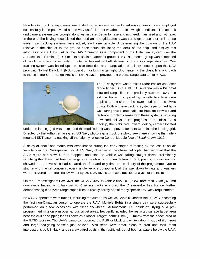
New landing tracking equipment was added to the system, as the look-down camera concept employed successfully in the past would not be very useful in poor weather and in low light conditions. The up-look grid camera system was brought along just in case. Better to have and not need, than need and not have. In the end, the having necessitated the need and the grid camera was put to good use later on in these trials. Two tracking systems were added, each one capable of determining the position of the UAV relative to the ship or to the ground base setup simulating the deck of the ship, and display this information via a Data Link to the UAV Operator. One component of the Data Link system was the Surface Data Terminal (SDT) and its associated antenna group. The SDT antenna group was comprised of two large antennas securely mounted at forward and aft stations on the ship’s superstructure. One tracking system was based upon passive detection and triangulation of a laser beacon upon the UAV providing Normal Data Link (NDL) operation for long range flight. Upon entering the close, final approach to the ship, the Short Range Precision (SRP) system provided the precise range data to the MPCS.
The SRP system was a mixed radar tracker and laser range finder. On the aft SDT antenna was a Distomat infra-red range finder to precisely track the UAV. To aid this tracking, strips of highly reflective tape were applied to one skin of the lower module of the UAVs onsite. Both of these tracking systems performed fairly well during these land trials, but frequent software and technical problems arose with these systems incurring unwanted delays to the progress of the trials. As a backup, the stabilized upward looking camera located
under the landing grid was tested and the modified unit was approved for installation into the landing grid. Directed by the author, an assigned US Navy photographer took the photo seen here showing the trailer-mounted SDT antenna tracking off the brightly reflective Control Module face of Sentinel A/V 1010. A delay of about one-month was experienced during the early stages of testing by the loss of an air vehicle over the Chesapeake Bay. A US Navy observer in the chase helicopter had reported that the A/V’s rotors had slowed, then stopped, and that the vehicle was falling straight down, preliminarily signifying that there had been an engine or gearbox component failure. In fact, post-flight examinations showed that a drive shaft had sheared, the first and only time in the history of the programme. Due to strict environmental concerns, every single vehicle component, all the way down to nuts and washers were recovered from the shallow water by US Navy divers to enable detailed analysis of the incident. On the 11th test flight at Pax River, the CL-227 MAVUS vehicle (A/V 1012) flew more than 60km (37.2mi) downrange hauling a Kollmorgan FLIR sensor package around the Chesapeake Test Range, further demonstrating the UAV’s range capabilities to readily satisfy one of many specific US Navy requirements. New UAV operators were trained, including the author, as well as Captain Charles Bell, USMC, becoming the first non-Canadian person to operate the UAV. Multiple flights in a single day were successfully performed on a few occasions with these “newbees”. Autonomous (i.e. hands-off) flying of a pre-programmed mission plan over various target areas, frequently included the restricted surface target area near the civilian shipping lanes known as “Hooper Target”, some 10km (6.2 miles) from the beach area of the SATD test site. The UAV’s camera’s recorded the FLIR or black and white video images of the target and large sea-going vessels just beyond. Also seen were small pleasure craft and their rapid interceptions by US Navy range safety patrol boats in the restricted, out-of-bounds waters below the UAV.
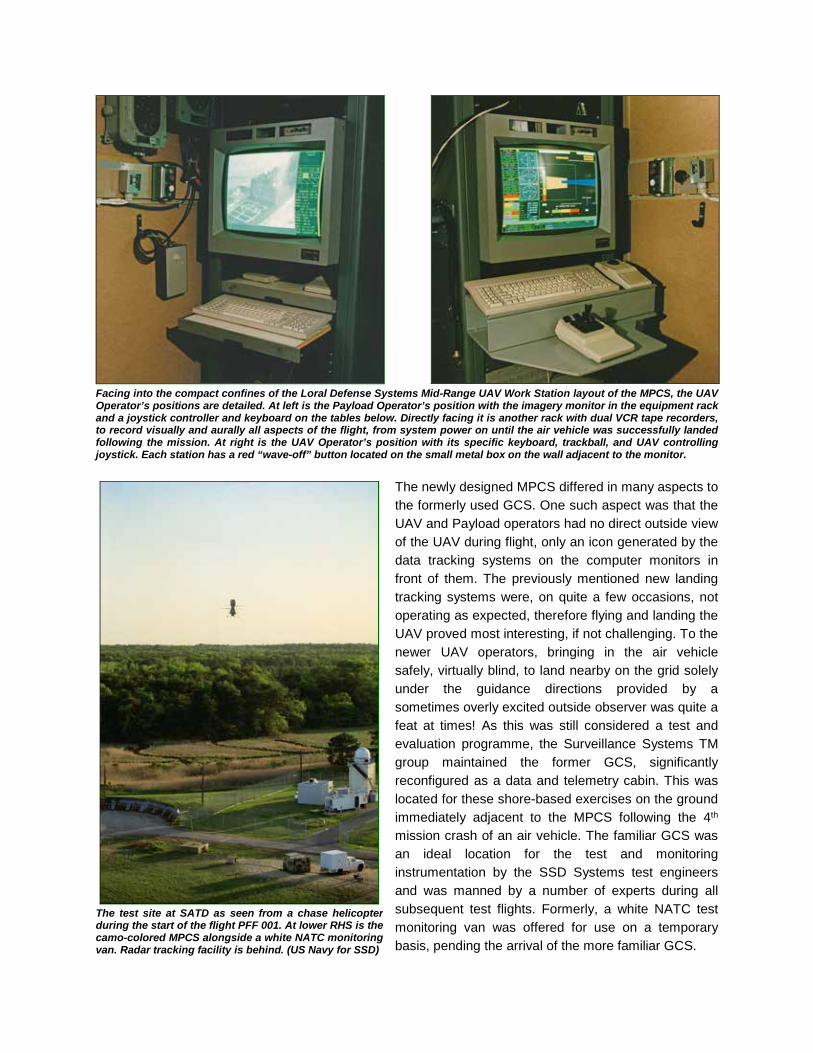
Facing into the compact confines of the Loral Defense Systems Mid-Range UAV Work Station layout of the MPCS, the UAV Operator’s positions are detailed. At left is the Payload Operator’s position with the imagery monitor in the equipment rack and a joystick controller and keyboard on the tables below. Directly facing it is another rack with dual VCR tape recorders, to record visually and aurally all aspects of the flight, from system power on until the air vehicle was successfully landed following the mission. At right is the UAV Operator’s position with its specific keyboard, trackball, and UAV controlling joystick. Each station has a red “wave-off” button located on the small metal box on the wall adjacent to the monitor.
The newly designed MPCS differed in many aspects to the formerly used GCS. One such aspect was that the UAV and Payload operators had no direct outside view of the UAV during flight, only an icon generated by the data tracking systems on the computer monitors in front of them. The previously mentioned new landing tracking systems were, on quite a few occasions, not operating as expected, therefore flying and landing the UAV proved most interesting, if not challenging. To the newer UAV operators, bringing in the air vehicle safely, virtually blind, to land nearby on the grid solely under the guidance directions provided by a sometimes overly excited outside observer was quite a feat at times! As this was still considered a test and evaluation programme, the Surveillance Systems TM group maintained the former GCS, significantly reconfigured as a data and telemetry cabin. This was located for these shore-based exercises on the ground immediately adjacent to the MPCS following the 4th mission crash of an air vehicle. The familiar GCS was an ideal location for the test and monitoring instrumentation by the SSD Systems test engineers and was manned by a number of experts during all subsequent test flights. Formerly, a white NATC test monitoring van was offered for use on a temporary basis, pending the arrival of the more familiar GCS.
The test site at SATD as seen from a chase helicopter during the start of the flight PFF 001. At lower RHS is the camo-colored MPCS alongside a white NATC monitoring van. Radar tracking facility is behind. (US Navy for SSD)
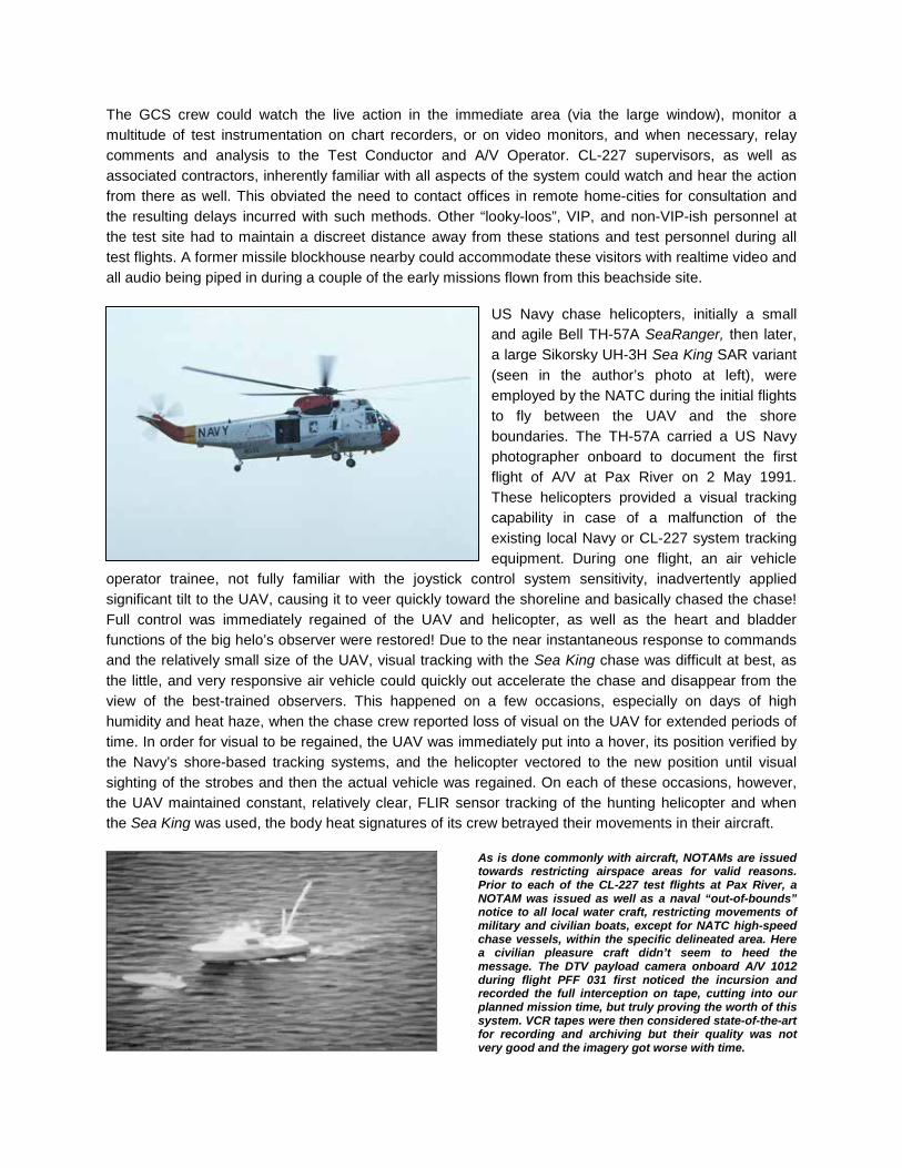
The GCS crew could watch the live action in the immediate area (via the large window), monitor a multitude of test instrumentation on chart recorders, or on video monitors, and when necessary, relay comments and analysis to the Test Conductor and A/V Operator. CL-227 supervisors, as well as associated contractors, inherently familiar with all aspects of the system could watch and hear the action from there as well. This obviated the need to contact offices in remote home-cities for consultation and the resulting delays incurred with such methods. Other “looky-loos”, VIP, and non-VIP-ish personnel at the test site had to maintain a discreet distance away from these stations and test personnel during all test flights. A former missile blockhouse nearby could accommodate these visitors with realtime video and all audio being piped in during a couple of the early missions flown from this beachside site.
US Navy chase helicopters, initially a small and agile Bell TH-57A SeaRanger, then later, a large Sikorsky UH-3H Sea King SAR variant (seen in the author’s photo at left), were employed by the NATC during the initial flights to fly between the UAV and the shore boundaries. The TH-57A carried a US Navy photographer onboard to document the first flight of A/V at Pax River on 2 May 1991. These helicopters provided a visual tracking capability in case of a malfunction of the existing local Navy or CL-227 system tracking equipment. During one flight, an air vehicle
operator trainee, not fully familiar with the joystick control system sensitivity, inadvertently applied significant tilt to the UAV, causing it to veer quickly toward the shoreline and basically chased the chase! Full control was immediately regained of the UAV and helicopter, as well as the heart and bladder functions of the big helo’s observer were restored! Due to the near instantaneous response to commands and the relatively small size of the UAV, visual tracking with the Sea King chase was difficult at best, as the little, and very responsive air vehicle could quickly out accelerate the chase and disappear from the view of the best-trained observers. This happened on a few occasions, especially on days of high humidity and heat haze, when the chase crew reported loss of visual on the UAV for extended periods of time. In order for visual to be regained, the UAV was immediately put into a hover, its position verified by the Navy’s shore-based tracking systems, and the helicopter vectored to the new position until visual sighting of the strobes and then the actual vehicle was regained. On each of these occasions, however, the UAV maintained constant, relatively clear, FLIR sensor tracking of the hunting helicopter and when the Sea King was used, the body heat signatures of its crew betrayed their movements in their aircraft.
As is done commonly with aircraft, NOTAMs are issued towards restricting airspace areas for valid reasons. Prior to each of the CL-227 test flights at Pax River, a NOTAM was issued as well as a naval “out-of-bounds” notice to all local water craft, restricting movements of military and civilian boats, except for NATC high-speed chase vessels, within the specific delineated area. Here a civilian pleasure craft didn’t seem to heed the message. The DTV payload camera onboard A/V 1012 during flight PFF 031 first noticed the incursion and recorded the full interception on tape, cutting into our planned mission time, but truly proving the worth of this system. VCR tapes were then considered state-of-the-art for recording and archiving but their quality was not very good and the imagery got worse with time.
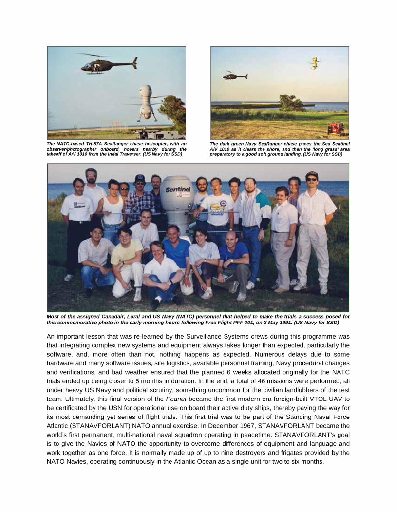
The NATC-based TH-57A SeaRanger chase helicopter, with an observer/photographer onboard, hovers nearby during the takeoff of A/V 1010 from the Indal Traverser. (US Navy for SSD)
The dark green Navy SeaRanger chase paces the Sea Sentinel A/V 1010 as it clears the shore, and then the ‘long grass’ area preparatory to a good soft ground landing. (US Navy for SSD)
Most of the assigned Canadair, Loral and US Navy (NATC) personnel that helped to make the trials a success posed for this commemorative photo in the early morning hours following Free Flight PFF 001, on 2 May 1991. (US Navy for SSD) An important lesson that was re-learned by the Surveillance Systems crews during this programme was that integrating complex new systems and equipment always takes longer than expected, particularly the software, and, more often than not, nothing happens as expected. Numerous delays due to some hardware and many software issues, site logistics, available personnel training, Navy procedural changes and verifications, and bad weather ensured that the planned 6 weeks allocated originally for the NATC trials ended up being closer to 5 months in duration. In the end, a total of 46 missions were performed, all under heavy US Navy and political scrutiny, something uncommon for the civilian landlubbers of the test team. Ultimately, this final version of the Peanut became the first modern era foreign-built VTOL UAV to be certificated by the USN for operational use on board their active duty ships, thereby paving the way for its most demanding yet series of flight trials. This first trial was to be part of the Standing Naval Force Atlantic (STANAVFORLANT) NATO annual exercise. In December 1967, STANAVFORLANT became the world’s first permanent, multi-national naval squadron operating in peacetime. STANAVFORLANT’s goal is to give the Navies of NATO the opportunity to overcome differences of equipment and language and work together as one force. It is normally made up of up to nine destroyers and frigates provided by the NATO Navies, operating continuously in the Atlantic Ocean as a single unit for two to six months.

USS Doyle FFG-39 Guided Missile Frigate and STANAVFORLANT official badges. (Courtesy Mark Roe) Once all flight performance criteria were met and operator proficiency and accuracy with the landing systems accomplished at Pax River, the way was cleared for deployment onto the USS Doyle to begin the at-sea demonstration phase of the MAVUS I programme during the last quarter of 1991.
All CL-227 system components were transported overseas via a USAF C-141B Starlifter aircraft, then by truck to the port city of Den Helder, in northern Holland, and installation of the equipment onto the ship begun shortly thereafter. With the largest piece of hardware, the MPCS, sitting at front, all of the CL-227 equipment was readily managed onto a single truck. All MAVUS hardware was assembled and installed in the starboard hanger normally used to house one of the two Sikorsky SH-60B Light Airborne Multi-Purpose System (LAMPS III) helicopters of HSL-46. Antennas were mounted to new fixtures on the superstructure. The Captain was quite reticent about this group of civilians aboard His ship, modifying His ship, damaging His anti-skid deck, taking up His crew quarters, eating in His Mess and displacing one of His prized helicopters. Even though the MAVUS crew was classed as Officers for the duration of the cruise, they got less respect than the regular ship’s crew. From October to December 1991, the three embarked MAVUS air vehicles (1008, 1011 & 1012), flying from the USS Doyle in the North Atlantic, performed in the STANAVFORLANT 1991 exercise which included ships from Canada, Great Britain, The Netherlands, Norway, Germany, Spain and Portugal, under the command of a Dutch Admiral. Imagery transmitted from the MAVUS air vehicles to the Doyle was re-broadcast simultaneously to the other ships outfitted with receiving equipment and monitors.

Space was at a premium in the starboard side hanger of the Doyle as the author and Mark Roe make final equipment installations at Den Helder, but in the end it all came together and some kind of workable order was finally achieved. The photographic evaluation and measurement visit back in September 1990 had paid off handsomely towards this effort.
The USS Doyle with the CL-227 and crew spotted on deck leaves the port of Den Helder. (Bill Upton Photo)
Canadian Navy participation in the exercise consisted of the HMCS Nipigon DDH 266. (Bill Upton Photo)
As seen from HMCS Nipigon, the USS Doyle and crew experience an otherwise lovely day for a cruise on the North Sea.

One of the Sentinel air vehicles, with a DTV payload installed, is prepared to launch for a mission from the heaving deck of the USS Doyle somewhere in the North Atlantic during November 1991. At left, the fuelling process is underway using the ship’s supply of JP-5 fuel allocated for its helicopters when embarked. At right, with the rotor blades installed and the main umbilical and air start line connected, the vehicle undergoes preflight preparations and checkout in rough sea conditions.
A coastal surveillance operation at Cape Wrath in Scotland was one of the first missions performed during this exercise, with military personnel and vehicle targets organized on the range in direct support. The CL-227 UAV, sometimes flying below the height of the cliffs at the shore, could not be seen nor heard by the targets and observers, according to reports. This somewhat ‘invisible’ capability provides Commanders of vessels at sea the ability to see, but not be seen. The MAVUS air vehicles made a total of seven flights, for some 8.5 mission hours off the USS
Doyle, also providing gunfire support, with some of the flying and tactical imagery sharing done concurrently with the SH-60 LAMPS III helicopters and other ships of the combined task force. The MAVUS integrated payloads included DTV and FLIR imagery sensors that could visually detect the ship or target from 7 to 15 nautical miles (13 to 28 km) with the DTV or up to 16 nautical miles (30 km) using the FLIR. Other specific UAV missions required the employment of Electronic Counter Measures (ECM)
or the Communications Relay payloads. It was readily demonstrated onboard ship that payloads could be changed in less than 30 minutes for changing mission requirements. On the third flight from the Doyle, a successful landing was made during a heaving, 25-degree ship roll, with only one landing leg locked in the grid.
The maximum radius of action from the ship was 32 nautical miles (60 km) with a demonstrated maximum airspeed of 145 km/h (90 mph). Severe weather conditions were experienced for about 8 of the 24 days at sea with wind speeds of up to 65 knots (120 km/h / 75 mph) and in Sea State 4 conditions.
Some may consider this akin to a Disneyland E-Ticket ride, but the CL-227 ship riders on the Doyle didn’t mind this too much. There was on occasion some tye-dyed decorating of the passages by a few of the ship’s company however.

This was a true stepping stone, and set the standards for all of the new generation of VTOL UAV’s to come. Onboard, US Navy Commander Al Hutchins was later quoted as saying that the CL-227 was two or three generations ahead of anything else at the time. Commanding Officer of the USS Doyle, Captain John Petrie, USN, later received the Association for Unmanned Vehicle Systems (AUVS) Operations Award for this deployment of the CL-227 Sea Sentinel. The Canadair team that accompanied the CL-227 MAVUS I system aboard the USS Doyle during this deployment consisted of Steve Raff, Andrew Leeming, Clifford Raff and Mark Roe. Andrew Sakamoto and Mark Adcock supplied additional support between the cities of Den Helder, Holland and Hamburg, Germany, then returned home to Montreal. Contractor partner Loral Conic provided their own equipment support technician, Russ Adkins, for the MPCS and associated data link systems. Company photographers Paul Sagala and John Wulfraat were positioned aboard the HMCS Nipigon until the flotilla reached England, whereupon John returned to Montreal and Paul went aboard the Doyle to finish the cruise.
The USS Doyle and embarked MAVUS system’s itinerary for the STANAVFORLANT 1991 deployment consisted of:
Sept 27 - Oct 20 Inport Den Helder, Netherlands and commence MAVUS equipment installation
Oct 21 - 26 Underway en route Hamburg, Germany Two MAVUS flights performed. The USS Doyle made the first successful launch and recovery from a warship of the MAVUS UAV.
Oct 26 Anchored Firth of Forth
Oct 27 Underway en route Hamburg, Germany One MAVUS flight performed
Oct 30 - Nov 03 Inport Hamburg, Germany
Nov 04 - 07 Underway en route Rosyth, Scotland
Nov 08 - 11 Inport Rosyth, Scotland
Nov 12 - 21 Underway Joint Maritime Course 913 The USS Doyle and Britain’s HMS Cleopatra surprised the Netherlands Task Force and simulated the destruction of almost the entire group with one strike.
Two MAVUS flights performed
Nov 22 - 25 Inport Newcastle, England
Nov 26 - 28 Underway en route London, England
Nov 28 - Dec 04 Inport London, England
Dec 05 - 16 Underway en route Mayport, Florida Two MAVUS flights performed, one air vehicle (1012) lost at sea
Dec 16 Inport Mayport, Florida
Dec 16 - 20 Removal of the CL-227 MAVUS and Loral support crews and equipment from the USS Doyle.

Following STANAVFORLANT 1991, The USS Doyle returns to its Mayport Naval Station homeport on 16 December decked out in full welcoming regalia and with most of the ship’s crew lined up on deck. A STANDARD surface-to-air missile is deployed on the forward guided missile launcher and the Phalanx Close-in Weapons System (CIWS) anti-missile Gatling gun dominates the top of the hangars aft. The author, along with CL-227 mechanic Mario Calve, welcomed and transported the tired MAVUS crew of Steve Raff, Cliff Raff, Andrew Leeming and Mark Roe, along with photographer Paul Sagala and Loral’s Russ Adkins to non-moving shore lodgings for quiet respite. There they received good not-sea-related food on dishes that did not slide back and forth across the table, drinks that were not known as “Bug Juice”, and most of all, very long, hot showers. Immediately following the departure of the flight crew home, the process of removing the MAVUS I system (A/V 1012 was lost at sea on 11 December) as expeditiously as possible was begun due to the Captain stipulating in no uncertain terms that He wanted this ‘stuff’ off of His ship. (Bill Upton Photo) In mid-1992, it was reported in the media that the United States Department of Defense (DoD) was attempting to expand its technologies in the field of unmanned air vehicles, with funding and aid to be supplied by the UAV Joint Programme Office (JPO), especially with regards to VTOL maritime configurations. The Flight International issue of 17-23 June 1992 reported that:
“The JPO gained information on operating a maritime UAV by “buying data” from the US Navy’s operational evaluation of Canadair’s rotary-wing CL-227 Sentinel under the maritimised (sic) VTOL UAV system (MAVUS) demonstration. The JPO considers the programme completed, although Congress has set aside $20 million for a follow-on MAVUS II.”
One might prevision about what consequences could possibly occur towards the future of the CL-227 and subsequent Bombardier UAV programmes when that purchase of data was made. In September 1991, the Surveillance Systems Division announced that a dedicated flight test facility would be established close to the Fort Sill US Army Artillery Center, in Lawton, Oklahoma. American headquarters and marketing was already well established in Washington, D.C., with support offices to be established in Wichita, Kansas where Bombardier had setup its aircraft flight test operations.

The original contention was that the Lawton facility, scheduled to become fully operational in early 1992, would be used for the final integration and flight testing of the CL-227 Sentinel UAV and the CL-289 (AN/USD-502) unmanned airborne surveillance drone system. Attempting to utilize the CL-289 system at this site was deemed impractical, so the facility concentrated solely on preparations to accept the CL-277. Engineering and mechanically capable personnel from around the Lawton area were recruited to participate in the programme, to give the impression of a fully “Americanized” operation, for potential sales and support, yet still employed under the Canadian-based Bombardier banner, following training by the remaining Canadair / Bombardier team. The hired Lawton crew consisted of Leigh Stevens, Rick Rutten, Dave Blackburn, Roy Remington, Danny Scarborough, Mark Wishart, and Berina Wise. The first set-up of the CL-227 system at Fort Sill began in July 1992, in order to initiate the final stage in the MAVUS I programme. This stage was to incorporate the first free flight autonomous approach and landing of a CL-227 UAV, using the newly developed Sierra Nevada Corporation's (SNC) prototype of the Common Automatic Recovery System (CARS-P). Roger Noury, the chief SNC systems engineer who had basically designed this landing system and the associated control software, spearheaded the autoland efforts during all stages of this development process. The CL-227 was to be the initial air vehicle testbed for the CARS-P system with a view towards perfecting the autoland system for other developing UAV / RPH projects. This prototype system was rigorously tested at the Montreal-based laboratories and the Tether Site with software updates to rectify some of the teething problems encountered, as is the norm for all new developing systems. In a short period of time, a reliable combination of the UAV and CARS-P was ready for the commencement of free flight tests.
One of the CL-227 air vehicles is being tether tested at Canadair with the early CARS-P system (on stair platform at center). Over a three-minute period of hover during this test, air vehicle dispersions were shown to be less than six inches. The aft SDT antenna, pointed directly at the Control Module’s skin is on the trailer at right. (Photo Courtesy Roger Noury)
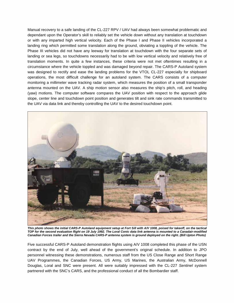
Manual recovery to a safe landing of the CL-227 RPV / UAV had always been somewhat problematic and dependant upon the Operator’s skill to reliably set the vehicle down without any translation at touchdown or with any imparted high vertical velocity. Each of the Phase I and Phase II vehicles incorporated a landing ring which permitted some translation along the ground, obviating a toppling of the vehicle. The Phase III vehicles did not have any leeway for translation at touchdown with the four separate sets of landing or sea legs, so touchdowns necessarily had to be with low vertical velocity and relatively free of translation moments. In quite a few instances, these criteria were not met oftentimes resulting in a circumstance where the vehicle toppled and was damaged beyond repair. The CARS-P Autoland system was designed to rectify and ease the landing problems for the VTOL CL-227 especially for shipboard operations, the most difficult challenge for an autoland system. The CARS consists of a computer monitoring a millimeter wave tracking radar system, which measures the position of a small transponder antenna mounted on the UAV. A ship motion sensor also measures the ship’s pitch, roll, and heading (yaw) motions. The computer software compares the UAV position with respect to the approach glide slope, center line and touchdown point position and generates tilt and sink rate commands transmitted to the UAV via data link and thereby controlling the UAV to the desired touchdown point.
This photo shows the initial CARS-P Autoland equipment setup at Fort Sill with A/V 1008, poised for takeoff, on the tactical TOP for the second evaluation flight on 19 July 1992. The Loral Conic data link antenna is mounted to a Canadair-modified Canadian Forces trailer and the Sierra Nevada CARS-P antenna system is ground deployed on the right. (Bill Upton Photo) Five successful CARS-P Autoland demonstration flights using A/V 1008 completed this phase of the USN contract by the end of July, well ahead of the government’s original schedule. In addition to JPO personnel witnessing these demonstrations, numerous staff from the US Close Range and Short Range UAV Programmes, the Canadian Forces, US Army, US Marines, the Australian Army, McDonnell Douglas, Loral and SNC were present. All were suitably impressed with the CL-227 Sentinel system partnered with the SNC’s CARS, and the professional conduct of all the Bombardier staff.

For the final flight of the first series of CL-227 Autoland free flight trials at Fort Sill, the formerly rag-tag looking group of Canadair/Bombardier/Lawton flight test crews adopted a somewhat common uniform – at least shirt-wise. This combined crew portrait, on 29 July, has the smiling, happy faces of L-R top: Danny Scarborough, Andrew Leeming, Pierre DeSerres, Samy Nasry, Gilles Saintonge, Kathy Leeming, Dave Blackburn and Roy Remington. L-R bottom: Rick Rutten, George Bokos, Mark Roe, Sophie Duchesne, Mark Wishart and Bill Upton. In October and December 1992, further CL-227 Autoland performance demos were carried out for several prospective operators, including flights for an official delegation from Saudi Arabia and representatives of the US Close Range UAV Programme Office. Initial training by the Bombardier based team of the new Lawton crew for some of the UAV operations was also performed at this time.
At the 1993 Paris Air Show, Bombardier announced that its Defense Systems Division (DSD) had been awarded a $10 million (US) contract to operationally evaluate the CL-227 Sea Sentinel automatic landing capabilities using an updated version of the CARS. This deployment was initially scheduled to take place on another US Navy frigate in the Caribbean in early 1994. The contract, designated MAVUS II, would assist the USN in further testing the effectiveness of a VTOL UAV with a small surface combatant. In preparation for this series of at-sea testing, new functions of the improved SNC CARS were integrated into the CL-227 Sea Sentinel system.
A short string of eleven tether test proving flights of the system at the Montreal facilities were performed from 22 December 1993 to 31 January 1994. These were necessary prior to shipping all associated hardware to the Lawton facilities for final system validation preceding the active deployment of the system. Along with re-testing the standard DTV and FLIR payloads, a Communications (Comms) Relay, then an Electronic Warfare (EW) mission payload were successfully test flown and proven in this series of tests and qualified for use with these UAVs.

The US Navy ship chosen for support to the MAVUS II series of tests was the Guided Missile Frigate USS Vandegrift (FFG-48), based out of the naval port at San Diego, California. The MAVUS II System was ship-based between February and mid-June 1994, with three objectives to fulfill. These were to first prove the new CARS automatic landing capabilities on a moving deck. Then, demonstrate the capabilities that this system can add to small surface combatants. Finally, to acquaint the US Coast Guard with the potential applications of VTOL UAVs on their patrol vessels including coastal surveillance and drug interdiction operations.
The Canadair/Bombardier crew selected for this second deployment of the CL-227 MAVUS consisted of Steve Raff, Andrew Leeming, George Bokos, with Samy Nasry assigned as technical support during the first two underways. Keith Monk provided in-port technical support. Luc Gerber was acting on behalf of the newly created Integrated Logistics Support (ILS) group, officially developed at the behest of the USN. Dave Blackburn and Roy Remington were assigned from the Lawton-based team. Sierra Nevada Corporation’s Roger Noury supported the CARS, and Loral Conic supplied personnel to look after their UAV control system. A US Navy Lieutenant was formally attached to the team and ship to supposedly report on the CL-227 tests. He was apparently very biased towards the Pioneer UAV and had little regard to something he knew little about - the CL-227. The Captain and crew were all new to the ship and the Captain was preparing his new charge for a commission in the Pacific. Various delays had occurred and the ship’s schedule was threatened, so the addition of the CL-227 system was nothing but an additional impediment, or threat, to getting the ship ready on time. The Captain’s main interest in the CL-227 system and test team was to get them off his ship, so he could do his proper job. Therefore, he refused to spare much time towards the CL-227 flight trials, preferring to go to sea a couple of times to test the ship’s weapons systems. These missions did not pan out as there were some sea turtles in the area and the weapons firing would have disturbed them, so it was curtailed. The CL-227 was not permitted to fly in lieu.
Somewhere in the Pacific Ocean, the deployed MAVUS II system is seen onboard the USS Vandegrift during the somewhat rare benign sea conditions encountered during CL-227 at-sea trials. With the main umbilical connector and air start line fully retracted, the dual foot clamps (red painted) have yet to release the air vehicle for takeoff. (Courtesy Roger Noury)
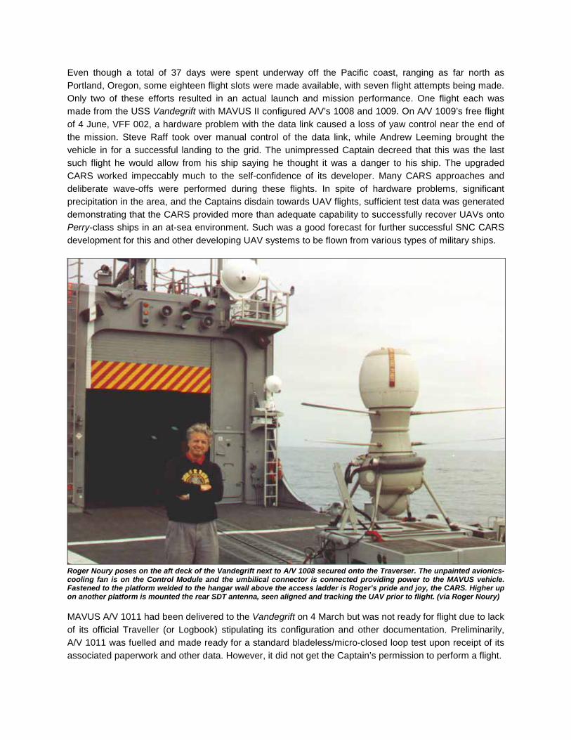
Even though a total of 37 days were spent underway off the Pacific coast, ranging as far north as Portland, Oregon, some eighteen flight slots were made available, with seven flight attempts being made. Only two of these efforts resulted in an actual launch and mission performance. One flight each was made from the USS Vandegrift with MAVUS II configured A/V’s 1008 and 1009. On A/V 1009’s free flight of 4 June, VFF 002, a hardware problem with the data link caused a loss of yaw control near the end of the mission. Steve Raff took over manual control of the data link, while Andrew Leeming brought the vehicle in for a successful landing to the grid. The unimpressed Captain decreed that this was the last such flight he would allow from his ship saying he thought it was a danger to his ship. The upgraded CARS worked impeccably much to the self-confidence of its developer. Many CARS approaches and deliberate wave-offs were performed during these flights. In spite of hardware problems, significant precipitation in the area, and the Captains disdain towards UAV flights, sufficient test data was generated demonstrating that the CARS provided more than adequate capability to successfully recover UAVs onto Perry-class ships in an at-sea environment. Such was a good forecast for further successful SNC CARS development for this and other developing UAV systems to be flown from various types of military ships.
Roger Noury poses on the aft deck of the Vandegrift next to A/V 1008 secured onto the Traverser. The unpainted avionics-cooling fan is on the Control Module and the umbilical connector is connected providing power to the MAVUS vehicle. Fastened to the platform welded to the hangar wall above the access ladder is Roger’s pride and joy, the CARS. Higher up on another platform is mounted the rear SDT antenna, seen aligned and tracking the UAV prior to flight. (via Roger Noury) MAVUS A/V 1011 had been delivered to the Vandegrift on 4 March but was not ready for flight due to lack of its official Traveller (or Logbook) stipulating its configuration and other documentation. Preliminarily, A/V 1011 was fuelled and made ready for a standard bladeless/micro-closed loop test upon receipt of its associated paperwork and other data. However, it did not get the Captain’s permission to perform a flight.
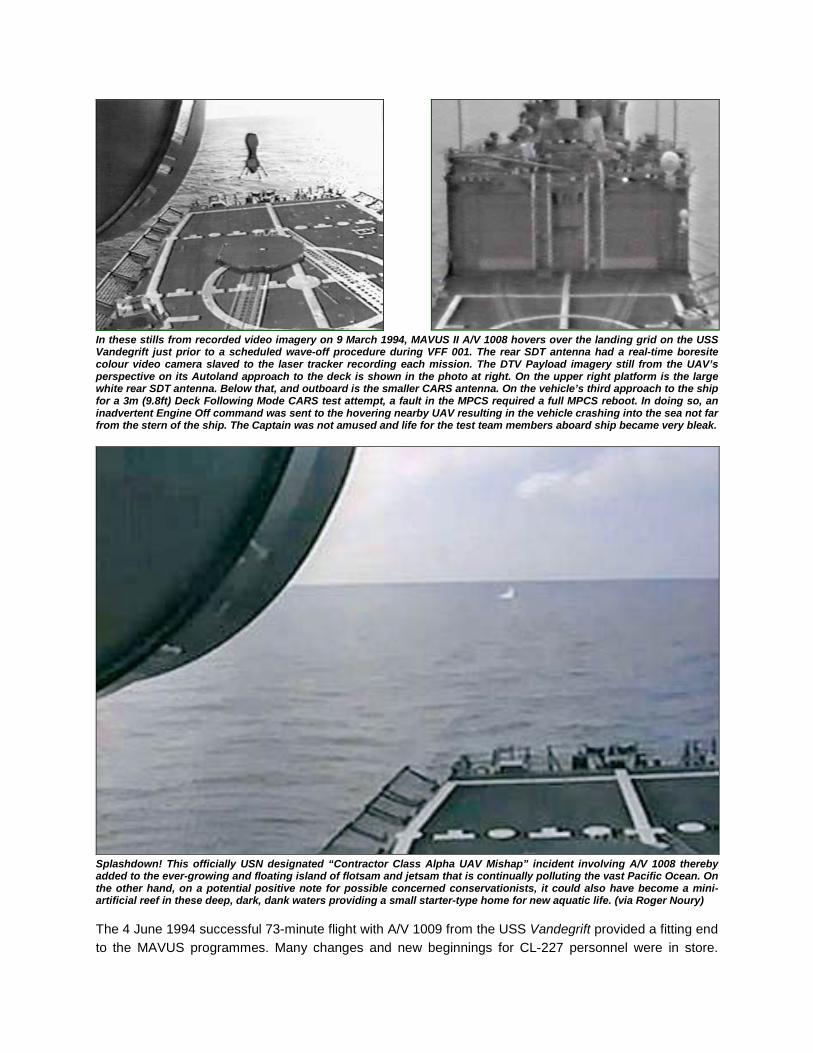
In these stills from recorded video imagery on 9 March 1994, MAVUS II A/V 1008 hovers over the landing grid on the USS Vandegrift just prior to a scheduled wave-off procedure during VFF 001. The rear SDT antenna had a real-time boresite colour video camera slaved to the laser tracker recording each mission. The DTV Payload imagery still from the UAV’s perspective on its Autoland approach to the deck is shown in the photo at right. On the upper right platform is the large white rear SDT antenna. Below that, and outboard is the smaller CARS antenna. On the vehicle’s third approach to the ship for a 3m (9.8ft) Deck Following Mode CARS test attempt, a fault in the MPCS required a full MPCS reboot. In doing so, an inadvertent Engine Off command was sent to the hovering nearby UAV resulting in the vehicle crashing into the sea not far from the stern of the ship. The Captain was not amused and life for the test team members aboard ship became very bleak.
Splashdown! This officially USN designated “Contractor Class Alpha UAV Mishap” incident involving A/V 1008 thereby added to the ever-growing and floating island of flotsam and jetsam that is continually polluting the vast Pacific Ocean. On the other hand, on a potential positive note for possible concerned conservationists, it could also have become a mini-artificial reef in these deep, dark, dank waters providing a small starter-type home for new aquatic life. (via Roger Noury) The 4 June 1994 successful 73-minute flight with A/V 1009 from the USS Vandegrift provided a fitting end to the MAVUS programmes. Many changes and new beginnings for CL-227 personnel were in store.

CL-227 Technology Transfer and Training Plans called for the Bombardier Lawton, Oklahoma facility to receive all remaining CL-227 hardware and documentation from Montreal to permit continued tether and free flight testing of the CL-227 towards performing the upcoming Engine Improvement Programme (EIP) and Avionics Improvement Programme (AIP) second phase trials. As a result, Montreal operations were scaled back considerably with ensuing department transfers and layoffs of many experienced personnel. Most of the few remaining engineering personnel were relocated to the new Bombardier Defence Systems Division (DSD) located at Mirabel International Airport, Quebec, to work on the CF-18 contract and the military derivatives of the Challenger business jets. A relatively skeleton test crew, absorbing the tasks of numerous departed co-workers (yet retaining only their own original salary), remained at Plant 4 to finish up a series of tether tests with A/V 1009, the last remaining vehicle to fly there. What formerly took up to nine people to accomplish a tether flight test was now reduced to three, one of them being a shanghaied CL-289 paper-pusher - and they were required to pack the equipment destined for Lawton as well. Then, without any fanfare, Plant 4 was finally closed down for good, where the Missiles & Systems Division had started it all so many years ago. History be damned, the land was required for an all important, and little used, golf course. On a side note, technically speaking, the last aerial vehicle that had the distinction to fly at Canada’s then oldest airfield, Cartierville, was the CL-227 Sentinel, A/V 1009, on 23 September 1994.
The last of the Montreal based Surveillance Systems Division personnel (the author being one) that were deemed pertinent to fully training the Lawton Division staff towards autonomous flight test operations, were recruited as part of a fully sanctioned CL-227 technology transfer programme. This was also known informally by all concerned as the, “taking our jobs away from us programme”. Animosity was rampant among the remaining employees towards the transfer to the United States of all of this proudly unique Canadian developed technology. One part of this transfer operation consisted of the manufacture of a dedicated Lawton Tether Test facility, mimicking
that of the original Montreal site. Somehow, the gung-ho Lawton personnel had gotten their hands on reprinted blueprint drawings of the 1979 original-built test site without requesting guidance from the only person left who had intimate design and construction knowledge of the original site (aka, the author). In a bid to prove how efficient their operations were going to be, they quickly engaged local contractors to build the massive steel tower structure. When the author arrived in November 1994 to ensure the mechanical aspects of the technology transfer were being performed properly, he had the task of informing the overly anxious Lawton crew of some problems with their tower assembly. When the original tower drawings were made, many by the author, it was supposed that this was going to be simply a one-off build. Therefore, no formal drawing revisions were ever planned for in a bid to save time and expense. During the fabrication process of the Canadair tower, verbal instructions and changes were made with regards to the assembly as required and an ad-hoc, pencil marked-up copy of some of the changes were made. As the author, Peter Ghey and Gilbert Ouellette helped to erect the 1979 tower in place, and hardware was being installed, additional on the spot modifications and structural rearrangements were performed to suit. These were never reflected on any drawing. Within a couple of months, the modernized and revamped tether test site was ready and CL-227 Phase 1 tests commenced.

Additional unrecorded modifications were made during the upgrade process for the Phase II and the later Phase III programmes. It took the author’s final six weeks with the Division to barely scratch the surface in trying to get the “Lawtoneers” to understand the rational for the all of the necessary changes. Rectifying the errors also took an exceptional amount of time in the overall construction of their own tether facility. Even with additional personnel added to the work crews, both locally and from Montreal, it was well over a year before a Lawton tether flight of a CL-227 Sentinel finally took place. Early in 1994, the Division received the contract for the EIP that was scheduled for completion by March 1996. In addition, a Research & Development (R&D) contract was received teaming Bombardier with Lear Astronics of Santa Monica, California, towards the first phase of the AIP. This phase was initially slated for completion by the fall of 1994. In the end, a series of AIP flights were performed with A/V 1009 at the new Lawton facility from May to July 1997.
Newly rebuilt A/V 1001 (re-serialled as 2992, with temporary solid metal landing legs) and A/V 1004 (now 2991) are posed with long-time CL-227 shop personnel Gilles Charette, Denis Maisonneuve, Mario Calvé, Gilles Rochon and Ken Nixon. They are seen with the “new” air vehicles outside the Canadair DSD Mirabel plant in May 1996. A/V 2992 (ex-1001) finally had its first ever free flight in February 1997. The EIP contract called for the integration into the air vehicles of an enhanced turboshaft engine, the new Williams WTS-125, rated at 125 shaft horsepower. A larger fuel tank was also incorporated onto the Power Module, giving it an overall somewhat bulbous look, towards demonstrating a three-hour endurance capability of the vehicle. The completion of this task fell upon the remnants of the former Montreal-based engineering and shop personnel (some now based at the Defence Systems Division, Mirabel, Quebec) and the test crew and facilities at Lawton, Oklahoma.
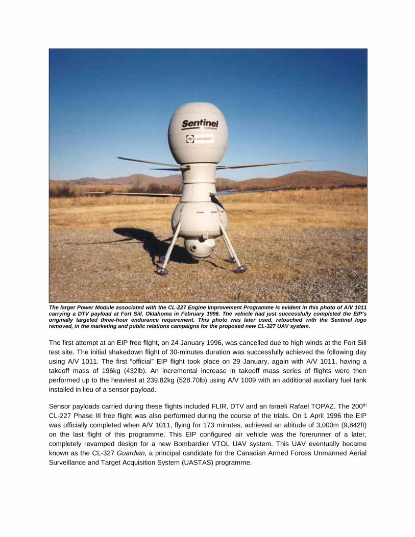
The larger Power Module associated with the CL-227 Engine Improvement Programme is evident in this photo of A/V 1011 carrying a DTV payload at Fort Sill, Oklahoma in February 1996. The vehicle had just successfully completed the EIP’s originally targeted three-hour endurance requirement. This photo was later used, retouched with the Sentinel logo removed, in the marketing and public relations campaigns for the proposed new CL-327 UAV system. The first attempt at an EIP free flight, on 24 January 1996, was cancelled due to high winds at the Fort Sill test site. The initial shakedown flight of 30-minutes duration was successfully achieved the following day using A/V 1011. The first “official” EIP flight took place on 29 January, again with A/V 1011, having a takeoff mass of 196kg (432lb). An incremental increase in takeoff mass series of flights were then performed up to the heaviest at 239.82kg (528.70lb) using A/V 1009 with an additional auxiliary fuel tank installed in lieu of a sensor payload. Sensor payloads carried during these flights included FLIR, DTV and an Israeli Rafael TOPAZ. The 200th CL-227 Phase III free flight was also performed during the course of the trials. On 1 April 1996 the EIP was officially completed when A/V 1011, flying for 173 minutes, achieved an altitude of 3,000m (9,842ft) on the last flight of this programme. This EIP configured air vehicle was the forerunner of a later, completely revamped design for a new Bombardier VTOL UAV system. This UAV eventually became known as the CL-327 Guardian, a principal candidate for the Canadian Armed Forces Unmanned Aerial Surveillance and Target Acquisition System (UASTAS) programme.
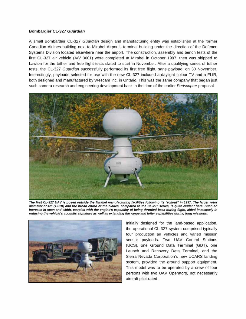
Bombardier CL-327 Guardian A small Bombardier CL-327 Guardian design and manufacturing entity was established at the former Canadian Airlines building next to Mirabel Airport’s terminal building under the direction of the Defence Systems Division located elsewhere near the airport. The construction, assembly and bench tests of the first CL-327 air vehicle (A/V 3001) were completed at Mirabel in October 1997, then was shipped to Lawton for the tether and free flight tests slated to start in November. After a qualifying series of tether tests, the CL-327 Guardian successfully performed its first free flight, sans payload, on 30 November. Interestingly, payloads selected for use with the new CL-327 included a daylight colour TV and a FLIR, both designed and manufactured by Wescam Inc. in Ontario. This was the same company that began just such camera research and engineering development back in the time of the earlier Periscopter proposal.
The first CL-327 UAV is posed outside the Mirabel manufacturing facilities following its “rollout” in 1997. The larger rotor diameter of 4m (13.1ft) and the broad chord of the blades, compared to the CL-227 series, is quite evident here. Such an increase in span and width, coupled with the engine’s capability of being throttled back during flight, aided immensely in reducing the vehicle’s acoustic signature as well as extending the range and loiter capabilities during long missions.
Initially designed for the land-based application, the operational CL-327 system comprised typically four production air vehicles and varied mission sensor payloads. Two UAV Control Stations (UCS), one Ground Data Terminal (GDT), one Launch and Recovery Data Terminal, and the Sierra Nevada Corporation’s new UCARS landing system, provided the ground support equipment. This model was to be operated by a crew of four persons with two UAV Operators, not necessarily aircraft pilot-rated.

This system was equally suited for maritime operations being designed to operate from all-sized naval vessels with a helicopter landing pad. All of the ground-based equipment was transported via a single general “High Mobility Multipurpose Wheeled Vehicle” (or “Humvee”) with supporting cargo / utility trailer. The interface between the UAV Operators and the UAV was via the UCS. The UCS consisted of two control stations implemented on two small identically configured portable ruggedized PC workstations. First an Air Vehicle Control Station, where the UAV Operator commanded the launch, in-flight and landing functions, monitored and reported on the A/V status, and performed in-flight plan updates. Second is the Payload Operator Station, where control of the payload was exercised, image exploitation and data manipulation was performed. Pre-mission planning and during mission payload image / data recording, interpretation and playback could be performed by these small workstations.
CL-327 Guardian Cutaway and Specifications (Modified drawing by Bill Upton) The 100-125 horsepower Williams International WTS117-5 Heavy Fuel Engine, a version of which had previously been demonstrated during the 1994-1996 EIP program, powered the bulbous CL-327. This engine was capable of running on diesel, JP-4, JP-5, JP-8, and JET-A fuels without reconfiguration. The WTS117 could be operated over a controllable speed range from 85,000 rpm to 104,800 rpm permitting minimum fuel consumption at cruise while providing maximum power at launch and climb. As with the earlier CL-227 Phase II and Phase III vehicles the engine was mounted vertically in the upper module surrounded by an upper fuel tank. A smaller, lower fuel tank was located below the avionics floor in the lower structure module supplying fuel to the engine via a propeller module fuel supply service pipe.

The more robust propeller module transmission and gearing was an upgraded version developed for the CL-227, designed to handle the maximum power available from the WTS117-5 engine. Rotor speed could be varied from 650 to 750 rpm for flight endurance and maximum power output. To allow an ample margin of control power for future growth, a differential collective yaw control system, similar to the type used on many helicopters, replaced the magnetic particle clutch assemblies used on the Phase III. Larger diameter composite rotor blades incorporated a rain erosion protection leading edge adhesive tape strip. The lower structure housed all of the avionics equipment, the fuel system pumping elements and lower fuel tank. It could support up to 100 kg (220 lbs) of mission sensor payload, all supported on four short shock absorbing landing struts, or probes for the maritime version. Two omnidirectional IFF transponder antennae were fitted 180° apart on the lower structure as well as two strobe lights acting as a visual cue and an effective anti-collision device. Some of the guidance and control systems included a fiber optics gyrocompass with integrated Global Positioning System (GPS) and Inertial Navigation System providing capability for autonomous flight, waypoint navigation or preprogrammed and automatic flight patterns. The GPS antenna was mounted on top of the air vehicle. A magnetometer in the lower structure fairing. Performance parameters showed the UAV could readily achieve a 100 nm (200 km) range while carrying a 100 kg (220 lb) payload. The Maximum Gross Take-Off Weight (MGTOW) of 350 kg (770 lbs) permitted a hover capability up to an altitude of 2,740 m (9,000 ft). It had an operating ceiling of 5,486 m (18,000 ft) and could achieve a maximum dash speed of 85 knots (157 km/h / 98 mph). Range was slated at nominally 100 km (62 miles) with an optional capability out to 200 km (124 miles). With a 50 kg (110 lb) payload installed, the available time on station at 100 km was limited to 4.75 hours, or 3.5 hours at a range of 200 km. Mission endurance was rated at 6.25 hours.
A CL-327 Guardian after launch displays the large annular opening for the engine intake ducts. A GPS antenna is atop the upper module. Two IFF antennae and strobe light are visible on the lower structure. No functional payload is being carried. Interestingly, following the somewhat successful flight trials of the ‘foreign-built’ MAVUS CL-227 UAVs from the Navy frigates USS Doyle and USS Vandegrift, US Navy funding for the maritime VTOL UAV programme ceased. Some speculation arose that the shelving of the Navy’s VTOL UAV plans was to allow United States contractors time to “catch-up” with a homegrown product. After a five year spending hiatus, the US Navy revived its interests in a VTOL UAV programme in 1997 with a new budget allocated towards land-based and at-sea flight trials of several American and two other systems. However, once again, the ‘foreign-built’ Bombardier CL-327 Guardian outshone the competition.
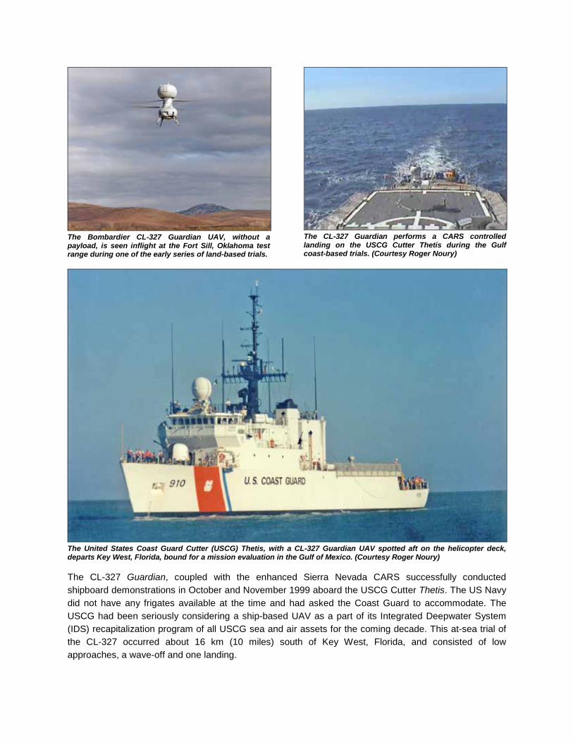
The Bombardier CL-327 Guardian UAV, without a payload, is seen inflight at the Fort Sill, Oklahoma test range during one of the early series of land-based trials.
The CL-327 Guardian performs a CARS controlled landing on the USCG Cutter Thetis during the Gulf coast-based trials. (Courtesy Roger Noury)
The United States Coast Guard Cutter (USCG) Thetis, with a CL-327 Guardian UAV spotted aft on the helicopter deck, departs Key West, Florida, bound for a mission evaluation in the Gulf of Mexico. (Courtesy Roger Noury) The CL-327 Guardian, coupled with the enhanced Sierra Nevada CARS successfully conducted shipboard demonstrations in October and November 1999 aboard the USCG Cutter Thetis. The US Navy did not have any frigates available at the time and had asked the Coast Guard to accommodate. The USCG had been seriously considering a ship-based UAV as a part of its Integrated Deepwater System (IDS) recapitalization program of all USCG sea and air assets for the coming decade. This at-sea trial of the CL-327 occurred about 16 km (10 miles) south of Key West, Florida, and consisted of low approaches, a wave-off and one landing.
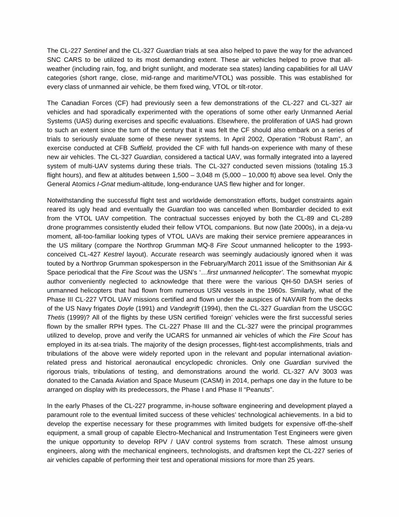
The CL-227 Sentinel and the CL-327 Guardian trials at sea also helped to pave the way for the advanced SNC CARS to be utilized to its most demanding extent. These air vehicles helped to prove that all-weather (including rain, fog, and bright sunlight, and moderate sea states) landing capabilities for all UAV categories (short range, close, mid-range and maritime/VTOL) was possible. This was established for every class of unmanned air vehicle, be them fixed wing, VTOL or tilt-rotor. The Canadian Forces (CF) had previously seen a few demonstrations of the CL-227 and CL-327 air vehicles and had sporadically experimented with the operations of some other early Unmanned Aerial Systems (UAS) during exercises and specific evaluations. Elsewhere, the proliferation of UAS had grown to such an extent since the turn of the century that it was felt the CF should also embark on a series of trials to seriously evaluate some of these newer systems. In April 2002, Operation “Robust Ram”, an exercise conducted at CFB Suffield, provided the CF with full hands-on experience with many of these new air vehicles. The CL-327 Guardian, considered a tactical UAV, was formally integrated into a layered system of multi-UAV systems during these trials. The CL-327 conducted seven missions (totaling 15.3 flight hours), and flew at altitudes between 1,500 – 3,048 m (5,000 – 10,000 ft) above sea level. Only the General Atomics I-Gnat medium-altitude, long-endurance UAS flew higher and for longer. Notwithstanding the successful flight test and worldwide demonstration efforts, budget constraints again reared its ugly head and eventually the Guardian too was cancelled when Bombardier decided to exit from the VTOL UAV competition. The contractual successes enjoyed by both the CL-89 and CL-289 drone programmes consistently eluded their fellow VTOL companions. But now (late 2000s), in a deja-vu moment, all-too-familiar looking types of VTOL UAVs are making their service premiere appearances in the US military (compare the Northrop Grumman MQ-8 Fire Scout unmanned helicopter to the 1993-conceived CL-427 Kestrel layout). Accurate research was seemingly audaciously ignored when it was touted by a Northrop Grumman spokesperson in the February/March 2011 issue of the Smithsonian Air & Space periodical that the Fire Scout was the USN’s ‘…first unmanned helicopter’. The somewhat myopic author conveniently neglected to acknowledge that there were the various QH-50 DASH series of unmanned helicopters that had flown from numerous USN vessels in the 1960s. Similarly, what of the Phase III CL-227 VTOL UAV missions certified and flown under the auspices of NAVAIR from the decks of the US Navy frigates Doyle (1991) and Vandegrift (1994), then the CL-327 Guardian from the USCGC Thetis (1999)? All of the flights by these USN certified ‘foreign’ vehicles were the first successful series flown by the smaller RPH types. The CL-227 Phase III and the CL-327 were the principal programmes utilized to develop, prove and verify the UCARS for unmanned air vehicles of which the Fire Scout has employed in its at-sea trials. The majority of the design processes, flight-test accomplishments, trials and tribulations of the above were widely reported upon in the relevant and popular international aviation-related press and historical aeronautical encyclopedic chronicles. Only one Guardian survived the rigorous trials, tribulations of testing, and demonstrations around the world. CL-327 A/V 3003 was donated to the Canada Aviation and Space Museum (CASM) in 2014, perhaps one day in the future to be arranged on display with its predecessors, the Phase I and Phase II “Peanuts”. In the early Phases of the CL-227 programme, in-house software engineering and development played a paramount role to the eventual limited success of these vehicles’ technological achievements. In a bid to develop the expertise necessary for these programmes with limited budgets for expensive off-the-shelf equipment, a small group of capable Electro-Mechanical and Instrumentation Test Engineers were given the unique opportunity to develop RPV / UAV control systems from scratch. These almost unsung engineers, along with the mechanical engineers, technologists, and draftsmen kept the CL-227 series of air vehicles capable of performing their test and operational missions for more than 25 years.

Some “borrowed” avionics and sophisticated electronic command and control equipment from the CL-89 and CL-289 programmes were an economical good start. Simple navigation and control systems were newly developed at the beginning to get through the early teething stage until it was realized that there was too much trial and error involved on limited budgets. It was thought that eventually going with existing products from established organizations would solve most of the problems that could be encountered. Later, it was found that these available systems were also not on a par with the technological leap of command and control of such vehicles, so it was back to the in-house drawing board. Specifically, when a supposed off-the-shelf navigational system did not meet the advertised performance specifications, our established small team of software and systems engineers stepped up to the plate. With dogged determination, they proved their worth by developing a workable and reliable system that eventually culminated in the latter years of the Phase III UAV’s success. Working principally from their compulsively clean desks, then literally getting their hands dirty on the actual air vehicles during tether and free flight trials, these engineers from Phase I to Phase III included; Ernie Semple, Fred Horst, Marius Huvers, Gareth Richardson, Bill Low, Ben Grass, Mark Adcock, Andrew Sakamoto, George Bokos, Francois Marcil, Cliff Raff, Steve Raff, Kevin McCarthy, Claude Tessier, Keith Monk, Bernie Ferrier, Yves Roy, Geoff Canfield, Andrew Foster, Pierre de Serres, Tracy Lloyd, Frank Szarka, and Samy Nasry.
Before the advent of common early computer processors in Surveillance Systems during the early-1990s, the truly unsung personnel that were indispensable were the totally overworked engineering secretarial staff. These ladies ran the place since the early days. If any reports, tables of statistics or memos needed to be typed and distributed each day (almost always required by 20-30 engineers, managers, and group leaders and all “as soon as possible”), they did it on their trusty mechanical typewriters at sometime lightning speeds. Otherwise, such necessary paperwork just wouldn’t be read or actioned via the standard old boy’s network of verbal communications. Computers, the early “Macs”, that nearly every engineer and technologist had on their desk in the 1990s, eventually relieved these ladies of some of their hair-greying workloads. Cudos go to specifically Denyse Parisien, Madelon Geukers Hanley, Jan Harrison, and Holly McMinn of the Design and Test Groups. In addition, what could one say about the Managers? Surprisingly, despite high blood pressure, stress and worry, they managed to survive we underlings and helped us to produce quality hardware that was often second-to-none in the industry.
The CL-227 flight-test team members were the most visible and often mentioned personnel. This was due to their tasks of proving and displaying the end product of the endeavors of literally hundreds of design and manufacturing personnel behind the scenes – so many, too numerous to mention. Many toiled for years, and even decades, others for short periods of contracted work. Regardless, they all deserve recognition of their unique efforts. Hence this historical record. After more than 35 years unfortunately some of the many names and faces have become somewhat blurred with time. The author, with close ties to the Photographic and Public Relations Departments, made it a point to ensure that SSD personnel received copies of photos and relevant PR material to show to their families and friends what they were achieving. Trying to describe to them the likes of a flying human-tall “peanut” with rotor blades and cameras is not an everyday image to normal folk. That’s where the photos and PR information came in.
Ignorance of Canada’s technological achievements seems de rigor in the face of the huge marketing campaigns waged by competitors south of the 49th Parallel in their efforts to play catch-up. With seemingly unlimited conflict-related financial resources at their disposal, more advanced products of familiar preconceived designs eventually emerge, albeit well after the path has been paved by innovative Canadian engineering and technological efforts. The Canadair Limited and Bombardier Surveillance Systems Department’s design, development and test personnel should be sincerely flattered and proud for their pioneering accomplishments.

“Happy Snaps” Numerous members of the total CL-227 Engineering Group and personnel from the Manufacturing Group were chosen for the top-rung job of being temporarily assigned to the Flight Test Group when the need arose. Most, due to their special skill sets, expertise, and determined work ethics were fortunate enough to be on nearly every off-site assignment. However, personnel from the other CL-227 Engineering Groups were wont to be assigned off-site and they had the sometimes pleasure of being away from home and seeing to the successful - or not - culmination of a CL-227 free-flight test or demonstration. They were duly considered part of the offsite team. Seen following are some of the “Happy Snaps” of many of the unsung engineering personnel who had the somewhat enviable task of being on a CL-227 Flight Test Team away from the Montreal-based facilities. The author made it a tradition that every team member received a commemorative 8x10 photograph to ‘prove’ he / she had been there. These were for showing to families and friends who were curious as to their job functions in regards to a flying, human-sized remotely piloted vehicle called the “Peanut”. Other than the overall group photos seen elsewhere in this history, here, in chronological order are seen some of the rest of the CL-227 Phase III design and test personnel who were somewhat willing participants in the prestigious flight test programme. Formalities and professionalism during flights dictated that the team adopt common phonetic terms relative to the team members position or function. ALPHA was for the A/V Operator, BRAVO was the Image Interpreter, TC stood for Test Conductor, TANGO stood for Telemetry, and ROMEO was for the RCS Operator.
DRES, 17 February 1988. In the GCS following the third CL-227 Phase 3 freeflight, (F-R) Vic Chang, Ron Leblanc, Kevin McCarthy, Steve Raff, Bill Upton
DRES, 18 February 1988. (L-R rear) Vic Chang, Ron Leblanc, Kevin McCarthy, Yves Roy, Andrew Leeming, A/V 1003, Bill Upton, Ron Rose, Gareth Richardson. (L-R front) Keith Monk, Steve Raff, Mark Roe
DRES, 03 June 1988. (L-R rear) Yves Roy, Andrew Leeming, A/V 1002, Dave Roe, Bill Upton, Mark Roe. (L-R front) Tracy Lloyd, Kevin McCarthy, Ron Leblanc
DRES, 10 June 1988. Don Lovegrove, Dave Roe, Andrew Leeming, A/V 1002, Yves Roy, Ron Leblanc, Mark Roe, Bill Upton, Tracy Lloyd
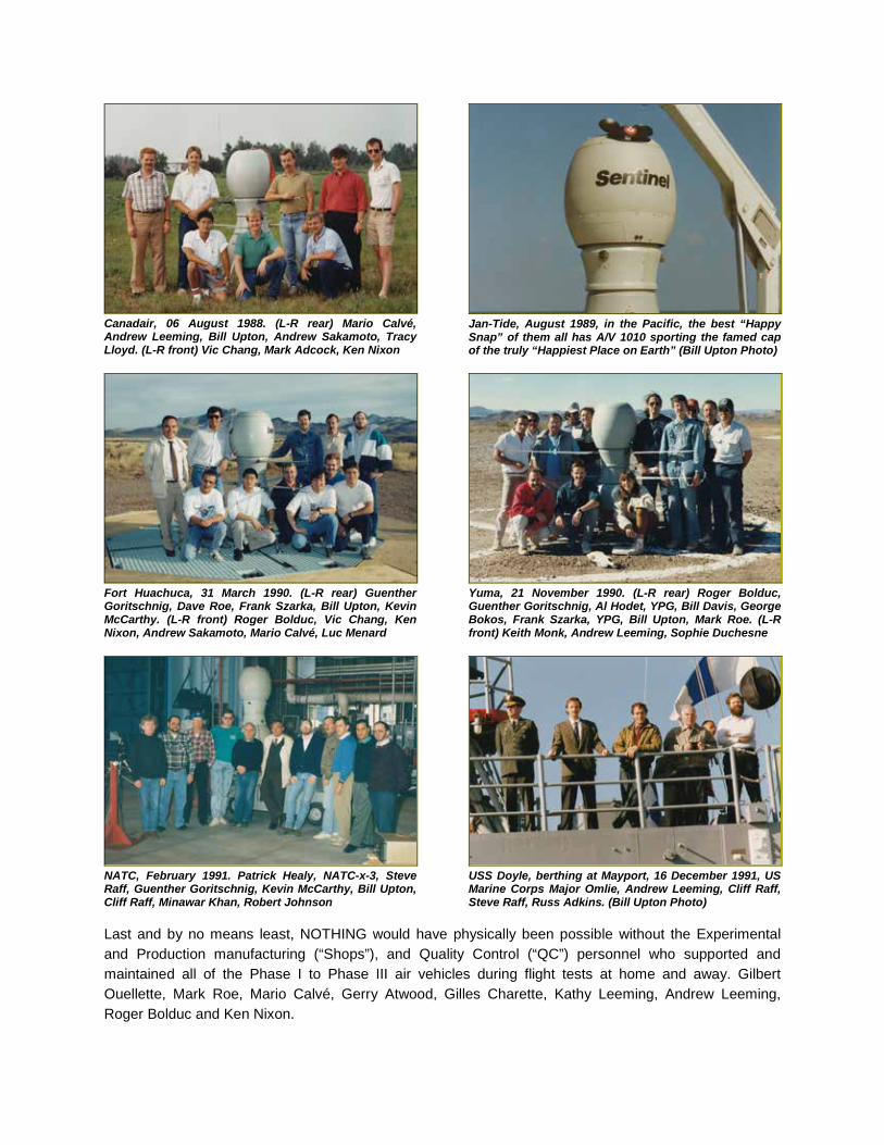
Canadair, 06 August 1988. (L-R rear) Mario Calvé, Andrew Leeming, Bill Upton, Andrew Sakamoto, Tracy Lloyd. (L-R front) Vic Chang, Mark Adcock, Ken Nixon
Jan-Tide, August 1989, in the Pacific, the best “Happy Snap” of them all has A/V 1010 sporting the famed cap of the truly “Happiest Place on Earth” (Bill Upton Photo)
Fort Huachuca, 31 March 1990. (L-R rear) Guenther Goritschnig, Dave Roe, Frank Szarka, Bill Upton, Kevin McCarthy. (L-R front) Roger Bolduc, Vic Chang, Ken Nixon, Andrew Sakamoto, Mario Calvé, Luc Menard
Yuma, 21 November 1990. (L-R rear) Roger Bolduc, Guenther Goritschnig, Al Hodet, YPG, Bill Davis, George Bokos, Frank Szarka, YPG, Bill Upton, Mark Roe. (L-R front) Keith Monk, Andrew Leeming, Sophie Duchesne
NATC, February 1991. Patrick Healy, NATC-x-3, Steve Raff, Guenther Goritschnig, Kevin McCarthy, Bill Upton, Cliff Raff, Minawar Khan, Robert Johnson
USS Doyle, berthing at Mayport, 16 December 1991, US Marine Corps Major Omlie, Andrew Leeming, Cliff Raff, Steve Raff, Russ Adkins. (Bill Upton Photo)
Last and by no means least, NOTHING would have physically been possible without the Experimental and Production manufacturing (“Shops”), and Quality Control (“QC”) personnel who supported and maintained all of the Phase I to Phase III air vehicles during flight tests at home and away. Gilbert Ouellette, Mark Roe, Mario Calvé, Gerry Atwood, Gilles Charette, Kathy Leeming, Andrew Leeming, Roger Bolduc and Ken Nixon.

Bombardier CL-427
As with most aviation design concerns, studies of a product’s future growths and concepts are projected in a bid to satisfy changing requirements and upgrades in technology. Such projection studies had started on the CL-227 Phase III series back in 1989 and were frequently updated and modified to suit potential circumstances. The final amalgamation of some of these proposals (updated in 1993) is shown below.
The CL-427 was to be a fifth generation of the VTOL RPV / UAV system developed by Canadair and Bombardier for flight-test evaluations towards potential sales and use by the military, based again, on the CL-227 UAV concept. The first incarnation of this complete redesign process for a new high-speed VTOL Tactical UAV (TUAV) began with the name CL-427 Kestrel applied to it. Following a significant redesign process wherein the design more closely mimicked the pre-existing CL-227 series, yet was considered an enhanced version of the CL-327 Guardian for the United States Tactical UAV requirement, the project then acquired the title CL-427 Goblin, later changed to the more pleasing Puma TUAV. Unfortunately very little in the way of information, drawings and even less photography was retained documenting the design processes, construction and flight trials for historical record purposes. Kestrel
By 1993, the CL-427 high-speed VTOL design, named Kestrel, was already seen as a radically revised concept of the former CL-227 peanut-shaped family, having been tailored for the high-speed regime demanded for in emerging contract proposals. To make the most of existing CL-227 design efforts, as much hardware commonality as possible was retained for the new CL-427. Such components comprised the former propeller module swashplate and contra-rotating rotor hubs arrangement, upgraded rotors, similar DTV and FLIR payloads, and an uprated Williams International WTS-125 gas turbine engine with a revised gearbox arrangement. Body shape refinements were concentrated primarily on the tail fin arrangement with either a single T-tail, dual vertical surfaces on a stub wing or a dual downward V-tail being proposed. Compound-shaped composite material panels would be used for the body using the manufacturing technology base amassed decades earlier in Canadair for all conceptions of the CL-227 air vehicles. A small, scaled model was made for examination but the project did not progress any further.

Goblin / Puma
Computer-based design studies were soon after in progress for the originally named Canadair CL-427 that was questionably dubbed with the creepy moniker of Goblin at first, and for only a short period of time. When further along the design trail and partnerships were being sought, the air vehicle system soon acquired the stealthier sounding name of Puma. Bombardier teamed up with partners Lear Astronics, Loral, Sparta, Frontier, Rafael and Williams International for the marketing and construction of components and hardware to prove this concept of an affordable tactical UAV. The existing CL-227 Phase III’s A/V 1009 was chosen as the base model for the prototype of this variant. It sported new exterior skins, shaped somewhat akin to that of a bicycle racer’s streamlined helmet, fabricated and heavily riveted together for the Power
and Control Modules, replacing the original spherical-type panel segments. For the proposed test and production vehicles, the NACA 0035 airfoil shape would have been utilized. A large, flat-sided and swept back vertical ‘tail’ fin was installed atop the Power Module’s aft skin extension, most probably obviating the all important radar stealthiness that was deemed so inherent in the original CL-227 design philosophy.
Without resorting to wind tunnel tests beforehand, but with some tether tower flights performed at Lawton, it quickly became apparent during its singular, and brief, 1.5-minute flight at Fort Sill on 18 April 1996, that the shape actually decreased weathercock stability. This supposedly would not have occurred if the vehicle had been flown by the all-Lawton crew per the specified parameters as dictated by the Bombardier engineers. Such was the Lawton mindset. Further attempts to fly or plans to promote the configuration were panned for any continuing development. The modified air vehicle was later used more often as a static prop for US
Army publicity photographs for the TUAV concept, seen posed at Fort Sill with US Army personnel and proposed HMMMV light armored vehicle type transport and control vehicles in an arranged ‘operational’ looking environment. It is unknown what happened later as to the disposition of this particular air vehicle - most likely propped atop a barn somewhere in the United States’ mid-west area with a large letter “N” painted on the vertical fin!
The somewhat alien looking CL-427 Puma (aka formerly CL-227 A/V 1009) poses on the Fort Sill test range after its only flight. (Web Photo)
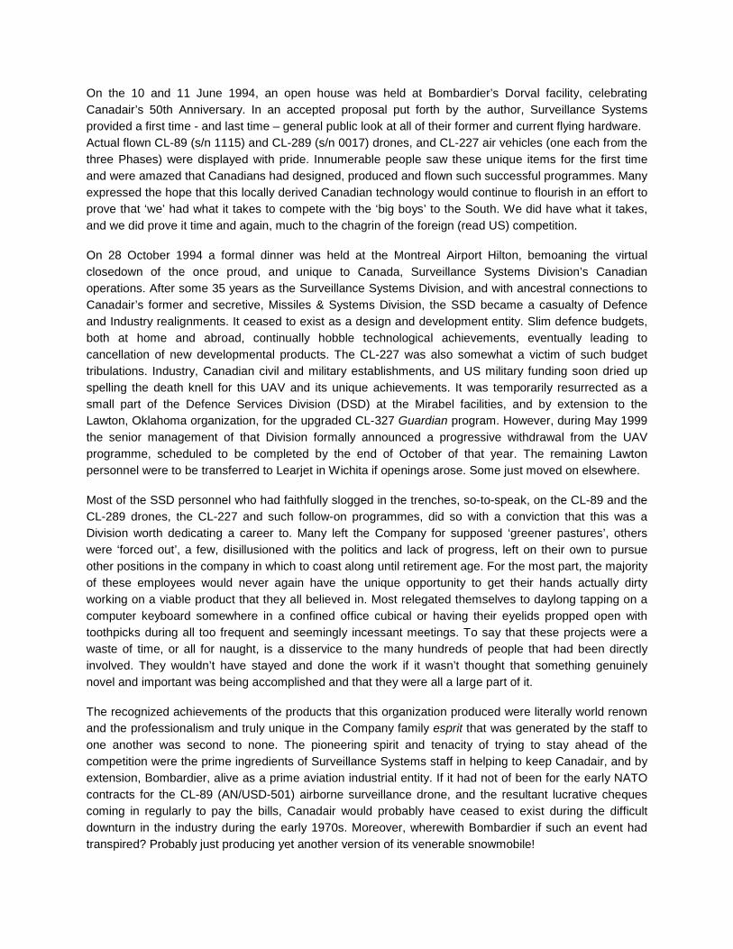
On the 10 and 11 June 1994, an open house was held at Bombardier’s Dorval facility, celebrating Canadair’s 50th Anniversary. In an accepted proposal put forth by the author, Surveillance Systems provided a first time - and last time – general public look at all of their former and current flying hardware. Actual flown CL-89 (s/n 1115) and CL-289 (s/n 0017) drones, and CL-227 air vehicles (one each from the three Phases) were displayed with pride. Innumerable people saw these unique items for the first time and were amazed that Canadians had designed, produced and flown such successful programmes. Many expressed the hope that this locally derived Canadian technology would continue to flourish in an effort to prove that ‘we’ had what it takes to compete with the ‘big boys’ to the South. We did have what it takes, and we did prove it time and again, much to the chagrin of the foreign (read US) competition. On 28 October 1994 a formal dinner was held at the Montreal Airport Hilton, bemoaning the virtual closedown of the once proud, and unique to Canada, Surveillance Systems Division’s Canadian operations. After some 35 years as the Surveillance Systems Division, and with ancestral connections to Canadair’s former and secretive, Missiles & Systems Division, the SSD became a casualty of Defence and Industry realignments. It ceased to exist as a design and development entity. Slim defence budgets, both at home and abroad, continually hobble technological achievements, eventually leading to cancellation of new developmental products. The CL-227 was also somewhat a victim of such budget tribulations. Industry, Canadian civil and military establishments, and US military funding soon dried up spelling the death knell for this UAV and its unique achievements. It was temporarily resurrected as a small part of the Defence Services Division (DSD) at the Mirabel facilities, and by extension to the Lawton, Oklahoma organization, for the upgraded CL-327 Guardian program. However, during May 1999 the senior management of that Division formally announced a progressive withdrawal from the UAV programme, scheduled to be completed by the end of October of that year. The remaining Lawton personnel were to be transferred to Learjet in Wichita if openings arose. Some just moved on elsewhere. Most of the SSD personnel who had faithfully slogged in the trenches, so-to-speak, on the CL-89 and the CL-289 drones, the CL-227 and such follow-on programmes, did so with a conviction that this was a Division worth dedicating a career to. Many left the Company for supposed ‘greener pastures’, others were ‘forced out’, a few, disillusioned with the politics and lack of progress, left on their own to pursue other positions in the company in which to coast along until retirement age. For the most part, the majority of these employees would never again have the unique opportunity to get their hands actually dirty working on a viable product that they all believed in. Most relegated themselves to daylong tapping on a computer keyboard somewhere in a confined office cubical or having their eyelids propped open with toothpicks during all too frequent and seemingly incessant meetings. To say that these projects were a waste of time, or all for naught, is a disservice to the many hundreds of people that had been directly involved. They wouldn’t have stayed and done the work if it wasn’t thought that something genuinely novel and important was being accomplished and that they were all a large part of it. The recognized achievements of the products that this organization produced were literally world renown and the professionalism and truly unique in the Company family esprit that was generated by the staff to one another was second to none. The pioneering spirit and tenacity of trying to stay ahead of the competition were the prime ingredients of Surveillance Systems staff in helping to keep Canadair, and by extension, Bombardier, alive as a prime aviation industrial entity. If it had not of been for the early NATO contracts for the CL-89 (AN/USD-501) airborne surveillance drone, and the resultant lucrative cheques coming in regularly to pay the bills, Canadair would probably have ceased to exist during the difficult downturn in the industry during the early 1970s. Moreover, wherewith Bombardier if such an event had transpired? Probably just producing yet another version of its venerable snowmobile!

CL-227 PHASE III Free Flights (FF) Performed Chronologically Canadair and DRES Free Flights 14 CFF 33 DFF *4 incidents total Jan Tide Ship Free Flights 9 SFF DRES Free Flights 6 DFF *2 incidents Fort Huachuca Free Flights 33 HFF *2 incidents Yuma Proving Grounds Free Flights 10 YFF NATC Patuxent River MAVUS I Free Flights 46 PFF *1 incident USS Doyle (MAVUS I) Free Flights 7 MFF *1 incident Lawton Autoland, Crew Training, and MAVUS II Free Flights 27 LFF USS Vandegrift (MAVUS II) Free Flights 2 VFF *1 incident Lawton EIP and AIP Free Flights 22 LFF *?? incidents Note: The written and photographic record keeping of the Phase III EIP, AIP, and subsequent free flight activities at Lawton and offsite became somewhat sporadic / unrecorded from April 1996 to 1999, therefore that part of the history has been lost.

CL-227 Phase III Air Vehicle’s Free Flight History and Dispositions A/V 1001 This air vehicle was the primary instrumented and frequently modified tether test vehicle for the duration of the initial part of the CL-227 Phase III programme, then it was placed in long-term storage. In May 1996, it was completely rebuilt by DSD personnel and received the new serial number 2992. It was shipped to Lawton along with A/V 1004 to supplement the test vehicles there. It finally performed its first free flight in February 1997, some ten years after it’s and the programme’s primary tether test flight in June 1987. It is also supposed that this was the vehicle used for a special Discovery Channel television production on such unmanned vehicles filmed in August 1997. Subsequent disposition is unknown. A/V 1002 The second of the instrumented heavyweight air vehicles performed 4 free flights at DRES in 1988. On 12 June 1988, at the end of a troublesome flight (DFF 013), the vehicle suffered a very hard vertical landing leaving deep impressions of the four footpads in the hard ground. It then climbed with some imparted tilt and during a short translation one of the landing legs hit a small knoll (the only one in the area) causing the air vehicle to tumble and crash. Some parts were scavenged and used to build A/V 1011 and 1012. A/V 1003 The last of the instrumented air vehicles, it was the first of the Phase III programme to be painted and seen for the official “rollout”, group pictures and public relations purposes. It was also used to perform the first free flight of the Phase III programme. It achieved a total of 12 free flights at Canadair and at DRES, all during 1988. It was also the first vehicle to record an incident, the jokingly coined “Lucky 13” flight during DFF 010 on 13 April 1988 while at DRES. Parts scavenged and used to build A/V 1011 and 1012. A/V 1004 The former and long serving “Hanger Queen”, A/V 1004 was used to verify the form and fitment of RAM onto an air vehicle prior to actual use in the field trials at Fort Huachuca. In 1991 was used as the PMTR test article for Rotor Blade Rain Erosion tests. It was eventually rebuilt at DSD in May 1996 and reserialed as 2991 in an effort to replenish the existing inventory at Lawton. It never accomplished a free flight and later was to be seen on static public display within a large glassed enclosure at the Montreal Science Center located on the King Edward pier in the Port of Montreal. Subsequent disposition is unknown. A/V 1005 This was considered to be the first of the “tactical” land configuration air vehicles, and was also the first of this Phase to be painted in a low-viz-grey paint scheme. Its first free flight was the unintentional one, aka the “Oops Flight” of CFF 002 on 30 July 1988. On 6 August, it finally performed the first official tactical configured free flight during CFF 003. It was later modified to the naval configuration (following A/V 1006). On 1 October 1988, upon takeoff from the Traverser for CFF 010, its 6th free flight, a large delta RPM excursion occurred immediately causing the air vehicle to yaw suddenly and pitch over into the ground. Some parts were scavenged and used to build A/V 1011 and 1012, and to repair other vehicles. A/V 1006 Air vehicle 1006 was the first in the line of the naval configured vehicles. An auspicious start to its short 3-flight test career had it proving the naval configuration and support equipment (Indal’s first Traverser and segmented landing grid) before a crowd of officials during CFF 004, the first NATO Naval Demo held on 11 August 1988. During CFF 006 on 20 August, while at 30m (98.4ft) the air vehicle tilted hardover, crashed and burned on the grassy field at Canadair.

A/V 1007 Supposedly charmed with the “Lucky 7” moniker, this was the air vehicle chosen to revamp the programme after a series of flight test incidents and a detailed overall design review. It had its first of 12 free flights, the 26th of the programme, on 26 April 1988 at Canadair. Shortly thereafter, while deployed to DRES its second flight resulted in the “Hellride” of the Navy Wooden Deck Demo, followed five days later by the successful demo on “HMCS Peanut”. Later, still at DRES, it performed a series of DND Phase I evaluation flights, and on 28 September 1989 during an hour-long flight, was used to successfully flight test and qualify the new 140cm (55in) diameter rotor blades. During a routine DRES flight (DFF 033) on 2 October 1989, while over Marker 5, the air vehicle suddenly yawed, crashed and burned on the range. A/V 1008 Air vehicle 1008 was the most prolific of the CL-227 UAVs, accomplishing a total of 75 free flights over a five year span. In July 1989, DND personnel began their training flights with this vehicle, the first non-Canadair personnel to operate the UAV. On 2 December 1989, A/V 1008 performed the final DRES flight recording an altitude of 2,500m (8,202ft), then, a month later, performed the first flight at Fort Huachuca, again with a full DND crew at the controls. While at Huachuca, this vehicle participated in the acoustic, IR and RAM clad air vehicle signature tests as well as the 40km (24.8mi) flight with the Army helicopter chase. At the end of flight HFF 024 the vehicle translated during the landing with one of the sea legs impacting the ground out of the grid and rotating the vehicle such as to prevent the other legs from engaging the grid. It toppled over with minimum damages incurred and was eventually rebuilt with some new and incident scavenged parts. On 21 November 1990, during flight YFF 005 at Yuma, Arizona, A/V 1008 had the distinction of performing the 100th CL-227 Phase III free flight, reaching an altitude of 3,000m (9,843ft) in the process. Later, at NATC Patuxent River, ship certification flights for MAVUS I were performed culminating in five successful flights flown off the USS Doyle at the end of 1991. From July 1992 to January 1994, all of the Lawton-based Autoland, crew training, and MAVUS II flights were added to A/V 1008’s repertoire. During LFF 022 on 19 January 1994, A/V 1008 recorded another significant flight in the history of the CL-227 with the 200th free flight of the overall programme. On 9 March 1994, while on the first MAVUS II flight from the USS Vandegrift, an MPCS computer reboot resulted in the engine being turned off during an approach to the stern of the ship, and A/V 1008 was lost at sea. A/V 1009 Free flight tests with this vehicle began at Fort Huachuca with flight HFF 002 on 10 January 1990. On HFF 011 it fulfilled the first flight of a CL-227 with a FLIR payload. During the final Fort Huachuca flight, a fuel burn evaluation in the Sea Sentinel configuration, A/V 1009 landed to the grid. However, with a slight tilt still applied, one sea leg probe impacted perfectly at the juncture of one of the grid squares, while an adjacent sea leg probe landed smack onto the uplook camera’s Plexiglas cover at the center of the grid and slid along it. With the vehicle unsecured, it toppled forward onto the grid with the still rapidly spinning rotor blades impacting the grid and progressively disintegrating with a sound somewhat akin to that of a wood chipper. Damage was slight and the vehicle was readily rebuilt with available spares. By the end of the year, A/V 1009 was again flying in Arizona, this time at the Yuma Proving Grounds where it was involved in the “Vega Antenna Azimuth Controller” saga. On 8 December 1990, during the last flight of this series, YFF 010, A/V 1009 set a flight endurance record for the CL-227 of 156 minutes, a record not surpassed until the advent of an EIP configured vehicle flight in February 1996. One flight with this vehicle from the USS Vandegrift on 4 June 1994 concluded the MAVUS programme. It ended its career as a CL-227 following the 199th Phase III free flight, at Lawton, when it became the heaviest such vehicle with a takeoff mass of 239.82kg (529lb). In March 1996, it was once again rebuilt, now as the CL-427 TUAV “Puma” shape and flown as such but once while at Lawton. Subsequent disposition is unknown.

A/V 1010 This, the last of the planned original CL-227 Phase III air vehicles, inaugurated its free flight career performing a series of required Navy Safety Demonstrations at the Canadair facilities preparatory to deployment on the M/V Jan Tide. Then, from 24 August to 16 September 1989, it was the principal air vehicle utilized for the Jan Tide exercise, the first CL-227 to fly from a ship at sea. Its next assignment came near the conclusion of the DRES trials, nearly concluding its own career as well. At touchdown following the 25 November 1989 flight DFF 035, A/V 1010 translated along the ground and toppled over. The damage was repaired but it was not until 2 May 1991 that this air vehicle flew again, commencing the arduous MAVUS I flight trials at NATC Patuxent River with a 10-minute flight, PFF 001. Just two days later, on its 18th free flight, during the outbound leg on the last of three scheduled rapid turnaround flights, the Navy chase helicopter observer reported a sudden descent of the vehicle and that the rotors had stopped. This was confirmed at the same time by live video feed from shore-based tracking cameras. A/V 1010 with its FLIR payload was seen to splash into a shallow section of the Chesapeake Bay and was completely recovered from a depth of about 9.0m (30 ft) the next day by a naval salvage team. A/V 1011 In a bid to conserve funding, two additional vehicles were added to the original ten, their principal structures were new with other assembly components selected from incident scavenged parts of other air vehicles and spares. The last CL-227 vehicle to start its free flight vocation, it presented a promising debut on 18 November 1991 when it flew with a FLIR payload providing gunfire support during mission MFF 005 from the USS Doyle. Its 30-minute introduction into an operational environment came to a close as a squall appeared and aborted the rest of that exercise. Following the MAVUS I trials, A/V 1011 languished, unused at Bombardier for the next few years. Somewhat of a respite came when A/V 1011, comprising some major components from A/V 1004, was put on static public display, alongside fellow Phase I and Phase II RPVs, and CL-89 and CL-289 surveillance drones at Canadair’s 50th Anniversary celebrations at Dorval in June 1994. Following the move of surveillance operations to Lawton, A/V 1011 was selected as the test article for the EIP flights, and as such a representation for the proposed CL-327 UAV. Rebuilt in 1995 with a new Williams WTS-125 engine in a larger Power Module to house more fuel, it performed 14 flights in this particular programme including the 200th Phase III free flight on 20 March 1996. It met its demise on 10 September 1996 during a demonstration flight at CFB Valcartier, Quebec. A/V 1012 The last of the CL-227 Phase III air vehicles was manufactured similarly to A/V 1011. During its six-month career it achieved 34 free flights all dedicated to the MAVUS I programme at Pax River and from the deck of the USS Doyle. While at Pax, during flight PFF 011, it recorded the longest range achieved during the Phase III programme of 60.8km (38mi). The author’s first free flight as an A/V Operator (PFF 013) as well as the first flight accomplished by a non-Canadian (Capt. C. Bell USMC) Operator was with A/V 1012. On the last, and its sole flight from the Doyle, A/V 1012 crashed into the sea 900m (2,953ft) from the ship. From February 1979 to December 1994, the author was a key member of the Canadair CL-227 mechanical design group and flight test team for all Phases of the CL-227 programme. As an avid aviation historian and photographer, he maintained personal records of events and also took many of the photographs, for public relations and record purposes, during the numerous flight trials. All photos, drawings, badges, patches, crests and stickers are from the author’s collection unless otherwise noted. Special thanks to: J.P. Cadieux, Marie Calvé, René Charette, Gilles Charette, Catherine Chase, Bob Deans, Peter Ghey, John Kerr, Terry Leversedge, Frank Lojko, Don Lovegrove, Bill Low, V.R. ‘Butch’ Miller, Ian Moody, Roger Noury (SNC), Ron Pickler, Steve Raff, John Robinson, Serge Rezukow, Dave Roe, Mark Roe, Andrew Sakamoto, Wayne Saunders, fellow CL-227 Flight Test Team crew members, Canadair’s Experimental Engineering staff: Janet Sturrock and Derek Gilmore and the Experimental “shops”; and the Photographic, Public Relations and Graphics Departments’ staff.