Embed Size (px)
Citation preview
THE CITY OF MOSS POINT, MISS ISS IPPI
theHOKPlanningGroup
J une 20 06
M O S S P O I N T D O W N T O W N R E N E W A L
D R A F T C O N T E N T S | 1
MOSS POINT DOWNTOWN RENEWAL
Contents
ACKNOWLEDGEMENTS
INTRODUCTION
RENEWAL PLAN
A. Vision & Goals
B. Immediate Actions
C. Plan Overview
D. Public Building Relocation
E. City Block Development
F. Riverfront Park Expansion & Improvement
G. Thoroughfare Improvements
H. Frontage
MOSS POINT DOWNTOWN SMARTCODE
M O S S P O I N T D O W N T O W N R E N E W A L
A C K N O W L E D G E M E N T S | 1D R A F T
MOSS POINT DOWNTOWN RENEWAL
Acknowledgements
The team wishes to express its sincere appreciation for the hard work and commitment brought to the effort by the offi cials and residents of the City of
Moss Point. City leaders, Commission members, and challenged us to do our best, most thoughtful work.
City of Moss Point
Xavier Bishop, MayorAneice Liddell, AlderwomanNancy Mims Norvel, Alderwoman Alfred C. Bodden III, Alderman Charles L Molden, AldermanTommy Hightower, AldermanJames Clinton Smith, Alderman
Moss Point Commission on Recovery, Rebuilding & Renewal
Steven Renfroe, Commission ChairLinda Holden, Economic Development Task Force ChairMonica Battle, Community Relations Task Force ChairBecky Jolly-Wood & Linda Wals, Quality of Life Task Force Co-ChairsDonna Joseph & Rachel Carpenter, Education Task Force Co-ChairsDaphne Viverette, Community Development Task Force ChairAneice Liddell, Infrastructure Task Force ChairMike Dale, Emergency Response & Preparedness Chair
M O S S P O I N T D O W N T O W N R E N E W A L
A C K N O W L E D G E M E N T S | 2D R A F T
Planning & Design Team
Town Planning & DesignSteven Schukraft, Colin Greene, Todd Meyer, Dhaval Barbhaya, Abbey Roberson, and Megan Holder, The HOK Planning Group
City Facility Programming & DesignMitch McNabb, Allred McNabb Architects
SmartCode CalibrationChad Emerson
TransportationRick Hall, Hall Planning & Engineering, Inc.
Architecture & DesignBruce Tolar, Tolar LeBatard Denmark Architects, PLLCClyde Judson, Judson & PartnersChristine G. H. Franck
IllustrationsDavid Carrico, Carrico Illustrations
Historic PhotographsDonald Lamie, Moss Point, MS
Charrette Organizers
The energy, skills, and passion of the charrette organizers should not go unrecog-nized. For the opportunity to work on this amazing project, we thank Governor Haley Barbour, Governor’s Commission chairman Jim Barkesdale, Congress for New Urbanism President John Norquist, and charrette leader Andres Duany of Duany Plater-Zyberk & Company.
For additional information on the report, please contact:
Steven Schukraft or Colin Greene The HOK Planning Group 3223 Grace Street NW Washington, DC 20007 [email protected] 202.339.8700
M O S S P O I N T D O W N T O W N R E N E W A L
I N T R O D U C T I O N | 1D R A F T
MOSS POINT DOWNTOWN RENEWAL
Introduction
Great things are happening in Moss Point. As the city moves through the post-Katrina stages of recovery, rebuilding, and renewal, a new sense of urgency is evident. City leaders and residents paint a compelling picture of a city on the mend, ready to leverage its strongest assets, tackle its toughest problems, and emerge from Katrina’s wake a more livable, beautiful, just, and sustainable community.
The Moss Point Downtown Renewal Plan and Downtown SmartCode, the
fi rst steps in a larger city-wide process of rebuilding and renewal, offers plans and strategies for the rebuilding and revitalization of downtown Moss Point. Building on the ideas presented in the Renewal Forum report and the existing Waterfront Plan, the plan and Smart-Code offer strategies for expanding the riverfront park and river walk, improv-ing walkability, narrowing Main Street, relocating city facilities out of the fl ood-plain, and guiding new investment.
Plan Organization
The report is organized in three sec-tions, including this introductory sec-tion, the Downtown Renewal Plan, and the Downtown SmartCode. The second section, the Renewal Plan, describes recommendations for downtown’s revi-talization. This section includes recom-mendations for the riverfront park, the relocation of public facilities, the re-
building of the city block, and guidance for the development of key frontages. The third section provides the primary tools for the plan’s implementation – the draft text and graphics of the Downtown SmartCode. A version of the Mississippi SmartCode customized specifi cally for application in downtown Moss Point.
M O S S P O I N T D O W N T O W N R E N E W A L
I N T R O D U C T I O N | 2D R A F T
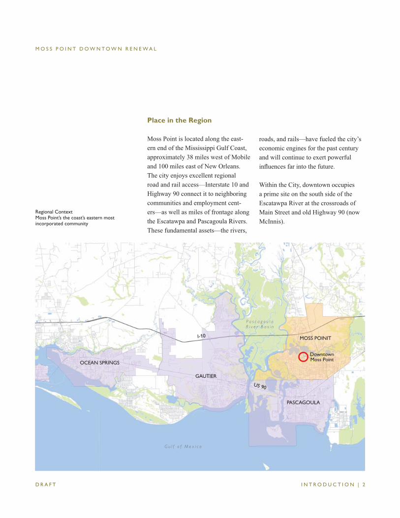
Place in the Region
Moss Point is located along the east-ern end of the Mississippi Gulf Coast, approximately 38 miles west of Mobile and 100 miles east of New Orleans. The city enjoys excellent regional road and rail access—Interstate 10 and Highway 90 connect it to neighboring communities and employment cent-ers—as well as miles of frontage along the Escatawpa and Pascagoula Rivers. These fundamental assets—the rivers,
MOSS POINIT
OCEAN SPRINGS
GAUTIER
PASCAGOULA
I-10
US 90
DowntownMoss Point
G u l f o f M e x i c o
Regional ContextMoss Point’s the coast’s eastern most incorporated community
P a s c a g o u l a R i v e r B a s i n
roads, and rails—have fueled the city’s economic engines for the past century and will continue to exert powerful infl uences far into the future.
Within the City, downtown occupies a prime site on the south side of the Escatawpa River at the crossroads of Main Street and old Highway 90 (now McInnis).
M O S S P O I N T D O W N T O W N R E N E W A L
I N T R O D U C T I O N | 3D R A F T
Development History
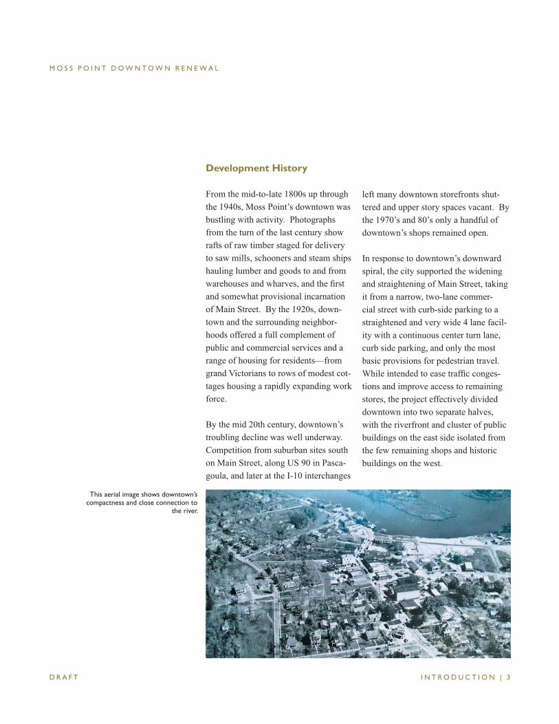
From the mid-to-late 1800s up through the 1940s, Moss Point’s downtown was bustling with activity. Photographs from the turn of the last century show rafts of raw timber staged for delivery to saw mills, schooners and steam ships hauling lumber and goods to and from warehouses and wharves, and the fi rst and somewhat provisional incarnation of Main Street. By the 1920s, down-town and the surrounding neighbor-hoods offered a full complement of public and commercial services and a range of housing for residents—from grand Victorians to rows of modest cot-tages housing a rapidly expanding work force.
By the mid 20th century, downtown’s troubling decline was well underway. Competition from suburban sites south on Main Street, along US 90 in Pasca-goula, and later at the I-10 interchanges
left many downtown storefronts shut-tered and upper story spaces vacant. By the 1970’s and 80’s only a handful of downtown’s shops remained open.
In response to downtown’s downward spiral, the city supported the widening and straightening of Main Street, taking it from a narrow, two-lane commer-cial street with curb-side parking to a straightened and very wide 4 lane facil-ity with a continuous center turn lane, curb side parking, and only the most basic provisions for pedestrian travel. While intended to ease traffi c conges-tions and improve access to remaining stores, the project effectively divided downtown into two separate halves, with the riverfront and cluster of public buildings on the east side isolated from the few remaining shops and historic buildings on the west.
This aerial image shows downtown’s compactness and close connection to
the river.
M O S S P O I N T D O W N T O W N R E N E W A L
I N T R O D U C T I O N | 4D R A F T
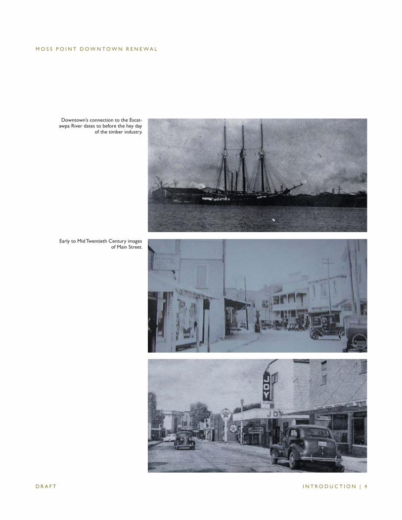
Downtown’s connection to the Escat-awpa River dates to before the hey day
of the timber industry.
Early to Mid Twentieth Century images of Main Street.
M O S S P O I N T D O W N T O W N R E N E W A L
I N T R O D U C T I O N | 5D R A F T
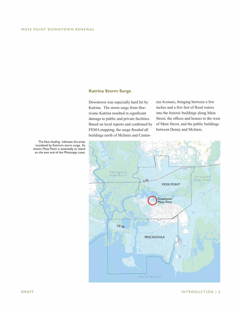
The blue shading indicates the areas inundated by Katrina’s storm surge. As
shown, Moss Point is essentially an island on the east end of the Mississippi coast.
MOSS POINT
PASCAGOULA
I-10
US 90
DowntownMoss Point
P a s c a g o u l a R i v e r B a s i n E s c a t a w p a
R i v e r B a s i n
G u l f o f M e x i c o
Katrina Storm Surge
Downtown was especially hard hit by Katrina. The storm surge from Hur-ricane Katrina resulted in signifi cant damage to public and private facilities. Based on local reports and confi rmed by FEMA mapping, the surge fl ooded all buildings north of McInnis and Casten-
era Avenues, bringing between a few inches and a few feet of fl ood waters into the historic buildings along Main Street, the offi ces and houses to the west of Main Street, and the public buildings between Denny and McInnis.
M O S S P O I N T D O W N T O W N R E N E W A L
I N T R O D U C T I O N | 6D R A F T
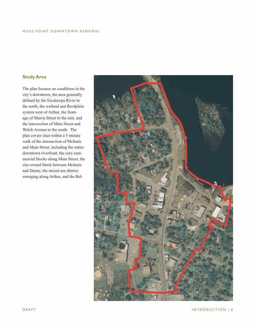
Study Area
The plan focuses on conditions in the city’s downtown, the area generally defi ned by the Escatawpa River to the north, the wetland and fl oodplain system west of Arthur, the front-age of Morris Street to the east, and the intersection of Main Street and Welch Avenue to the south. The plan covers sites within a 5 minute walk of the intersection of McInnis and Main Street, including the entire downtown riverfront, the core com-mercial blocks along Main Street, the city-owned block between McInnis and Denny, the mixed use district emerging along Arthur, and the Bel-
M O S S P O I N T D O W N T O W N R E N E W A L
I N T R O D U C T I O N | 7D R A F T
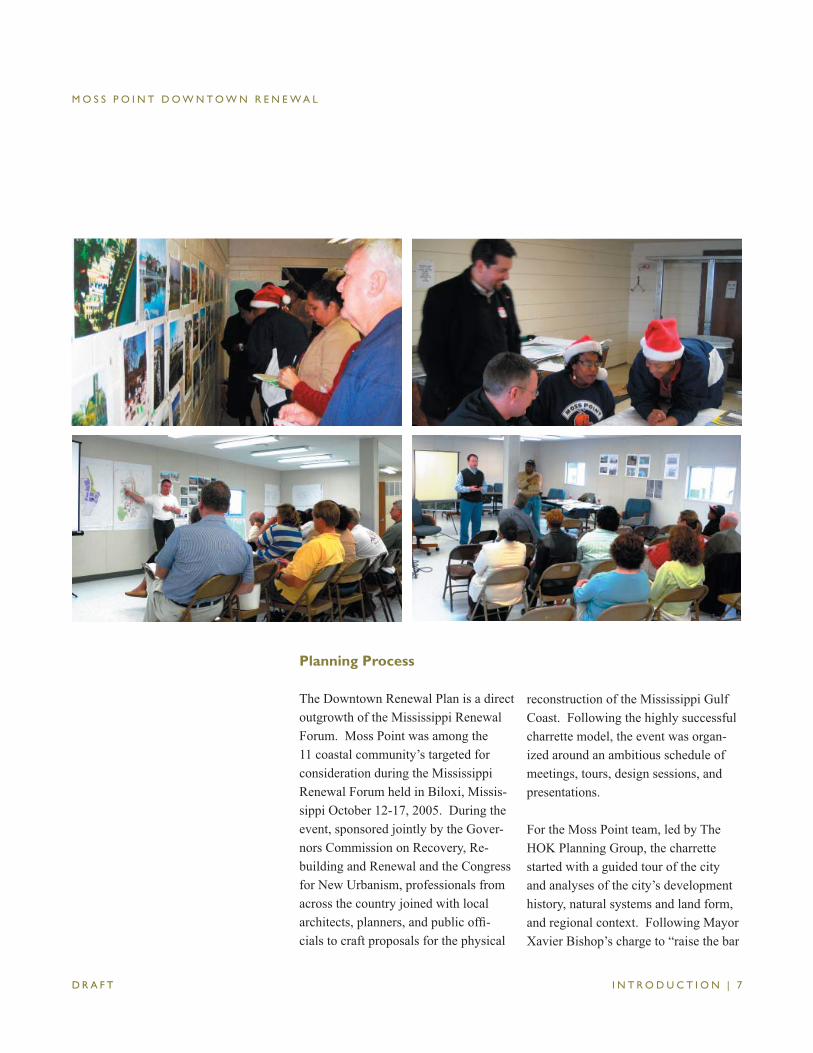
Planning Process
The Downtown Renewal Plan is a direct outgrowth of the Mississippi Renewal Forum. Moss Point was among the 11 coastal community’s targeted for consideration during the Mississippi Renewal Forum held in Biloxi, Missis-sippi October 12-17, 2005. During the event, sponsored jointly by the Gover-nors Commission on Recovery, Re-building and Renewal and the Congress for New Urbanism, professionals from across the country joined with local architects, planners, and public offi -cials to craft proposals for the physical
reconstruction of the Mississippi Gulf Coast. Following the highly successful charrette model, the event was organ-ized around an ambitious schedule of meetings, tours, design sessions, and presentations.
For the Moss Point team, led by The HOK Planning Group, the charrette started with a guided tour of the city and analyses of the city’s development history, natural systems and land form, and regional context. Following Mayor Xavier Bishop’s charge to “raise the bar
M O S S P O I N T D O W N T O W N R E N E W A L
I N T R O D U C T I O N | 8D R A F T
and be creative,” the team developed plans for rebuilding and renewal at 3 scales–the scale of the city, the scale of the neighborhood, and the scale of blocks and buildings. The ideas advanced in the plan set forth recom-mendations for stabilizing neighbor-hoods, capitalizing on the riverfront, revitalizing downtown, and attracting more sustainable forms of development and investment.
The Renewal Forum report encouraged city leaders to focus resources and at-tention to:
• kick-start downtown’s revitalization by leveraging potential funding for the relocation of city services and facilities, including City Hall, the Fire Station, and the Police Station;
• create a new village center and neighborhood in Escatawpa as part of a region-wide effort to attract quality development and provide housing for displaced families and individuals;
• support neighborhood stabilization and new housing initiatives city-wide, and in Kreole, to provide elderly housing, work force affordable hous-ing, and in- or near-neighborhood sites for relocation out of fl ood prone areas; and
• engage in efforts to make the city a destination for eco- and heritage-tourism and investment in clean industries, brownfi eld remediation and development, green building, and wetland/fl oodplain conservation and restoration.
Following the Renewal Forum, The HOK Planning Group team returned to present the Forum report and focus more closely on the downtown elements of the initial planning work. These ef-forts involved a number of workshops with the general public, city offi cials, and members of the Moss Commission on Recovery, Rebuilding & Renewal. During the series of workshops listed below, the team worked with commu-nity leaders to develop and refi ne the recommendations presented in the plan:
• Riverfront Park/Downtown Mini-Charrette, December 16-19, 2005
• SmartCode Workshop with the Moss Point Commission, February 19-20, 2006
• Plan & SmartCode Refi nements Workshop, April 25-27, 2006
• Transportation Work Session, May 15, 2006.
M O S S P O I N T D O W N T O W N R E N E W A L
R E N E W A L P L A N | 1 D R A F T
MOSS POINT DOWNTOWN RENEWAL
Renewal Plan
A. VISION & GOALS
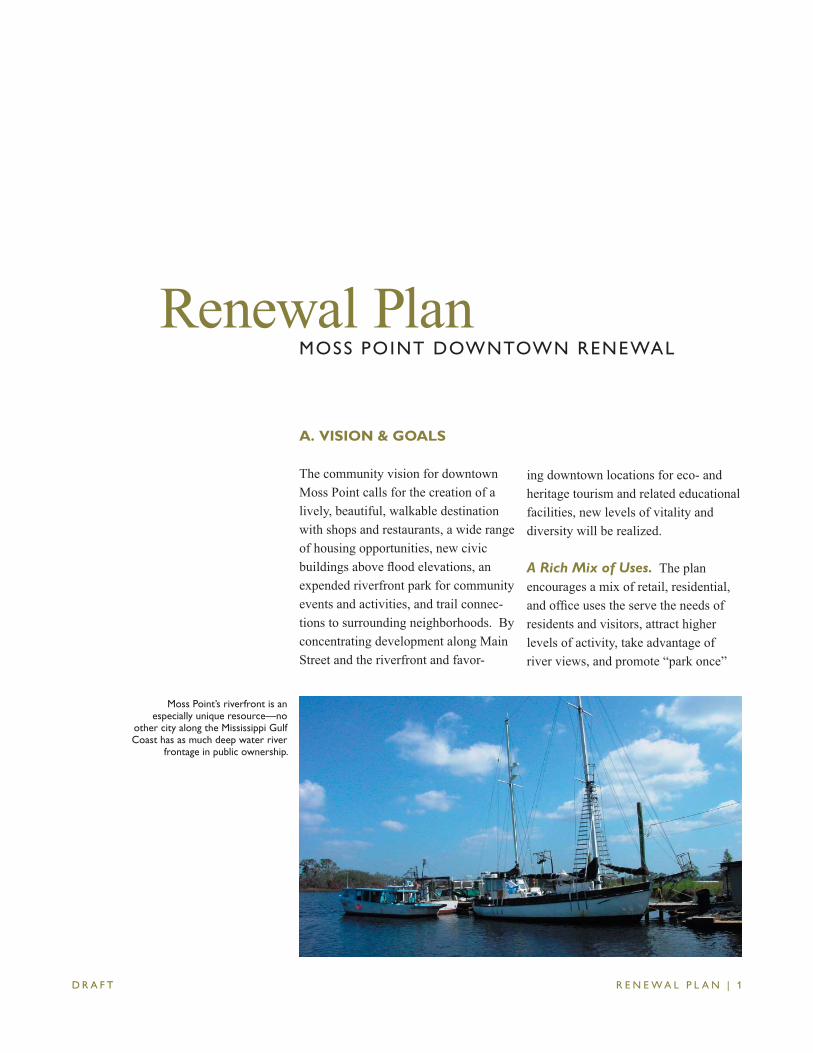
The community vision for downtown Moss Point calls for the creation of a lively, beautiful, walkable destination with shops and restaurants, a wide range of housing opportunities, new civic buildings above fl ood elevations, an expended riverfront park for community events and activities, and trail connec-tions to surrounding neighborhoods. By concentrating development along Main Street and the riverfront and favor-
ing downtown locations for eco- and heritage tourism and related educational facilities, new levels of vitality and diversity will be realized.
A Rich Mix of Uses. The plan encourages a mix of retail, residential, and offi ce uses the serve the needs of residents and visitors, attract higher levels of activity, take advantage of river views, and promote “park once”
Moss Point’s riverfront is an especially unique resource—no
other city along the Mississippi Gulf Coast has as much deep water river
frontage in public ownership.
M O S S P O I N T D O W N T O W N R E N E W A L
R E N E W A L P L A N | 2 D R A F T
opportunities. Pedestrian-oriented uses are favored over auto-dependent uses; shops and cafes with upper story hous-ing are recommended for sites over-looking the river; and a district of civic buildings is proposed for the Belleview Shopping Center site.
Walkable Streets. With walkability a central feature of the community’s vision, the plan recommends a series of improvements to the existing network of interconnected streets, including the provision of sidewalks, street trees, marked crosswalks, and on-street parking. Recommendations call for the redesign of existing streets to slow travel speeds, improve operations, serve evacuation needs, minimize cut-through traffi c, and increase safety and com-fort for pedestrians. Bridging the Main Street barrier is a central goal of the study.
Quality Public Spaces. The expan-sion and improvement of riverfront park is a centerpiece of the plan. With
Denny realigned and the boat ramps relocated, the park will become a place for public events and activities; resting and relaxation, and remembrance; and cultural expression.
Responsive Buildings. Encourage building forms and designs that support the creation of a safe and attractive public environment, bring life to Main Street and the riverfront, refl ect regional building and design traditions, and use resources wisely.
Sustainable Development. Public and private projects will be designed to spark sustainable investment while minimizing environmental impacts. Features like pervious paving, rain wa-ter harvesting systems, shade devices to minimize heat gain, and the use of na-tive plant species will be designed into future projects and serve as demonstra-tions of the community’s commitment to sustainable development.
M O S S P O I N T D O W N T O W N R E N E W A L
R E N E W A L P L A N | 3 D R A F T
B. IMMEDIATE ACTIONS
detailed engineering and design plans. Concurrently, prepare fi nal plans for the realignment of Arthur Street at the Belleview intersection.
• Initiate dialogue with potential devel-opers of the city block.
• Begin to prepare the city block for re-building consistent with the plan—fi -nalize plans for the realignment of Denny Street, establish precise limits of fi ll areas, demolish the recreation center, initiate relocation and modest raising of Denny Street.
• Adopt city policy establishing down-town as the favored location for retail and restaurants, arts and entertain-ment uses; and public investments to support culture, heritage, and eco tourism related activities.
The following strategies and actions, described in more detail below, repre-sent the fi rst critical steps towards the plan’s realization.
• Complete public review process for the Renewal Plan and SmartCode, fi nalize the plan and code, and seek adoption.
• Procure funding for the completion of site and building designs and detailed cost estimates for the new City Hall, Fire Station, Police Station, and recreation center consistent with the recommendation of the plan.
• Seek private developer interest in the construction and operation a water-front restaurant.
• Petition MDOT for approval to narrow Main Street from Dantzler to Belleview and seek funding for
M O S S P O I N T D O W N T O W N R E N E W A L
R E N E W A L P L A N | 4 D R A F T
C. PLAN OVERVIEW
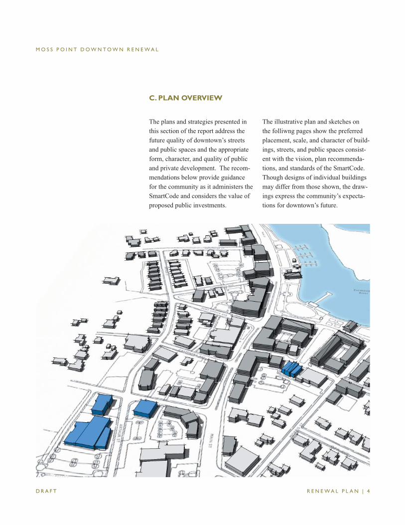
The plans and strategies presented in this section of the report address the future quality of downtown’s streets and public spaces and the appropriate form, character, and quality of public and private development. The recom-mendations below provide guidance for the community as it administers the SmartCode and considers the value of proposed public investments.
The illustrative plan and sketches on the folliwng pages show the preferred placement, scale, and character of build-ings, streets, and public spaces consist-ent with the vision, plan recommenda-tions, and standards of the SmartCode. Though designs of individual buildings may differ from those shown, the draw-ings express the community’s expecta-tions for downtown’s future.
M O S S P O I N T D O W N T O W N R E N E W A L
R E N E W A L P L A N | 5 D R A F T
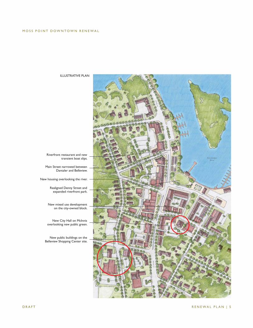
Realigned Denny Street and expanded riverfront park.
Riverfront restaurant and new transient boat slips.
New City Hall on McInnis overlooking new public green.
New housing overlooking the river.
New mixed use development on the city-owned block.
New public buildings on the Belleview Shopping Center site.
Main Street narrowed between Dantzler and Belleview.
ILLUSTRATIVE PLAN
M O S S P O I N T D O W N T O W N R E N E W A L
R E N E W A L P L A N | 6 D R A F T
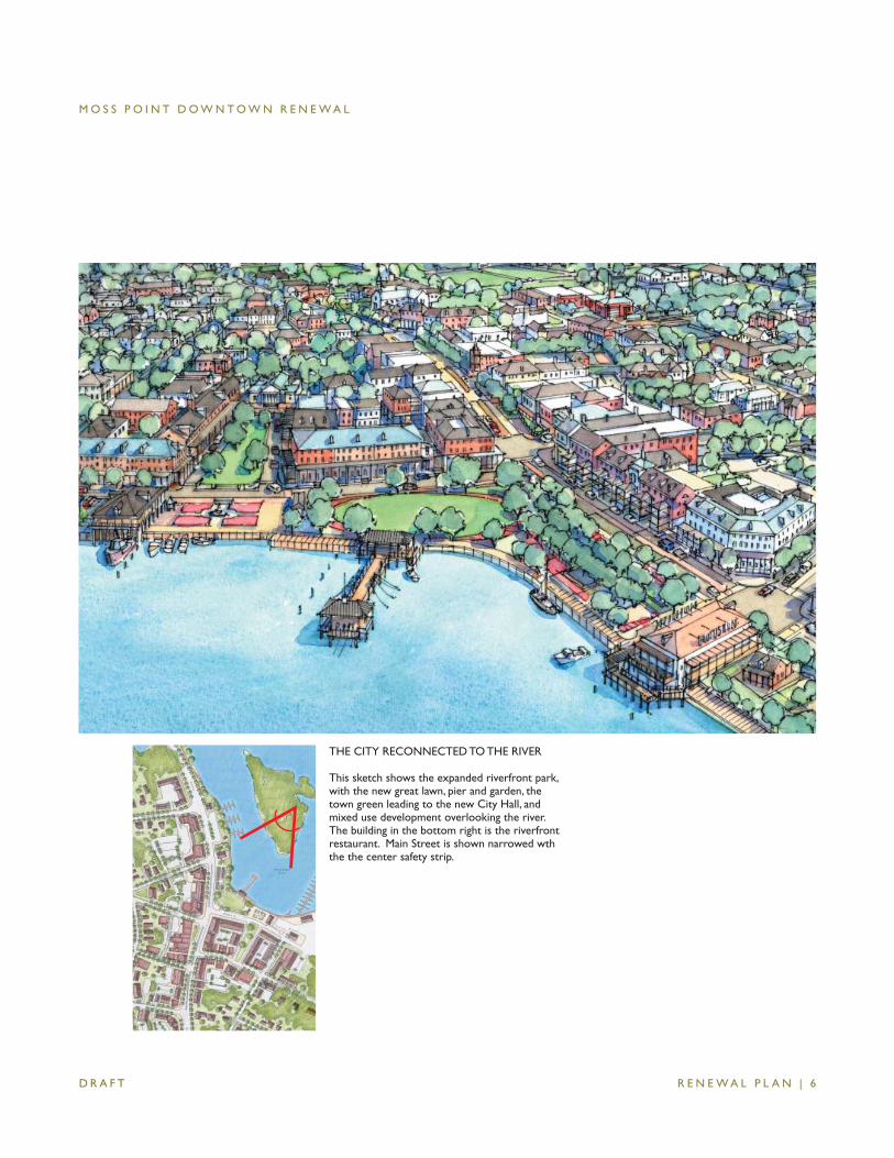
THE CITY RECONNECTED TO THE RIVER
This sketch shows the expanded riverfront park, with the new great lawn, pier and garden, the town green leading to the new City Hall, and mixed use development overlooking the river. The building in the bottom right is the riverfront restaurant. Main Street is shown narrowed wth the the center safety strip.
M O S S P O I N T D O W N T O W N R E N E W A L
R E N E W A L P L A N | 7 D R A F T
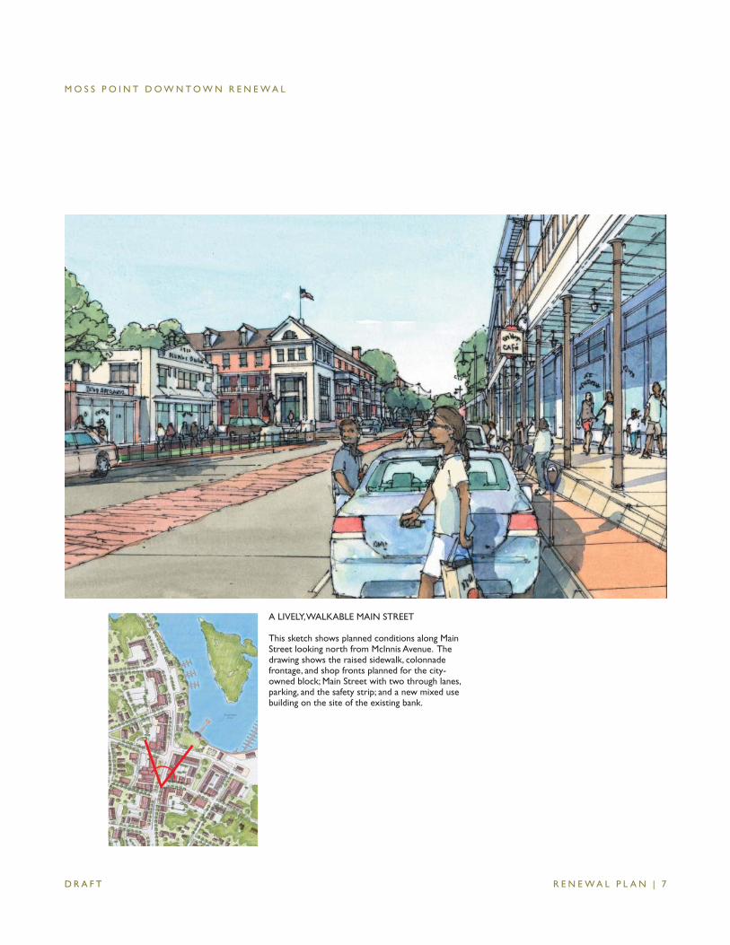
A LIVELY, WALKABLE MAIN STREET
This sketch shows planned conditions along Main Street looking north from McInnis Avenue. The drawing shows the raised sidewalk, colonnade frontage, and shop fronts planned for the city-owned block; Main Street with two through lanes, parking, and the safety strip; and a new mixed use building on the site of the existing bank.
M O S S P O I N T D O W N T O W N R E N E W A L
R E N E W A L P L A N | 8 D R A F T
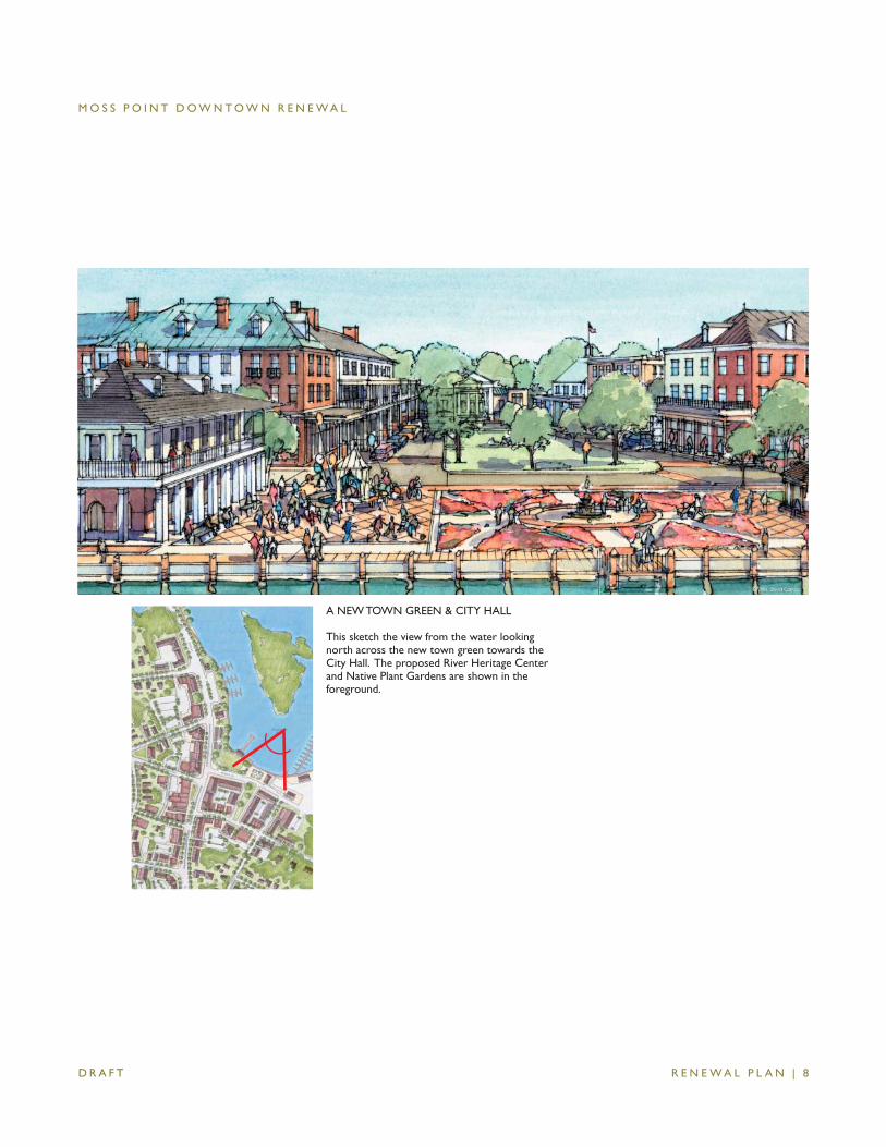
A NEW TOWN GREEN & CITY HALL
This sketch the view from the water looking north across the new town green towards the City Hall. The proposed River Heritage Center and Native Plant Gardens are shown in the foreground.
M O S S P O I N T D O W N T O W N R E N E W A L
R E N E W A L P L A N | 9 D R A F T
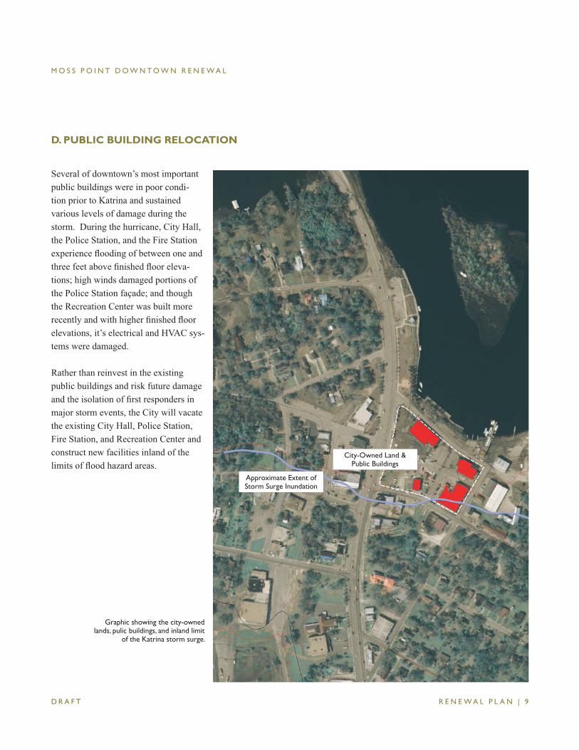
D. PUBLIC BUILDING RELOCATION
Graphic showing the city-owned lands, pulic buildings, and inland limit
of the Katrina storm surge.
City-Owned Land & Public Buildings
Approximate Extent of Storm Surge Inundation
Several of downtown’s most important public buildings were in poor condi-tion prior to Katrina and sustained various levels of damage during the storm. During the hurricane, City Hall, the Police Station, and the Fire Station experience fl ooding of between one and three feet above fi nished fl oor eleva-tions; high winds damaged portions of the Police Station façade; and though the Recreation Center was built more recently and with higher fi nished fl oor elevations, it’s electrical and HVAC sys-tems were damaged.
Rather than reinvest in the existing public buildings and risk future damage and the isolation of fi rst responders in major storm events, the City will vacate the existing City Hall, Police Station, Fire Station, and Recreation Center and construct new facilities inland of the limits of fl ood hazard areas.
M O S S P O I N T D O W N T O W N R E N E W A L
R E N E W A L P L A N | 1 0 D R A F T
A number of potential sites for the relo-cation of facilities were evaluated during the planning effort. Rising to the top of list where those out of the fl ood hazard area, owned by the City or available for purchase, and adequate in size to meet programmatic and parking requirements. Sites not considered attractive include those housing established businesses or in residential use on the edge of down-town. To maintain the central location and accessibility of key facilities and ensure they not become isolated by fl ood
waters (as could be the case if they were located further west), sites in or on the edge of downtown were favored over locations elsewhere in the City.
Descriptions of the new facility plans and site/building reuse strategies follow. These were developed in collaboration with the community and are based on preliminary program and design work completed by Pascagoula architect Mitch McNabb of Allred McNabb Architects.
City Hall
The existing City Hall will be vacated, demolished, and replaced by a new building outside the fl oodplain. The new building will house activities in the existing City Hall as well as additional meeting and offi ce spaces, work space for alderman, and offi ces for the city engineer and community development.
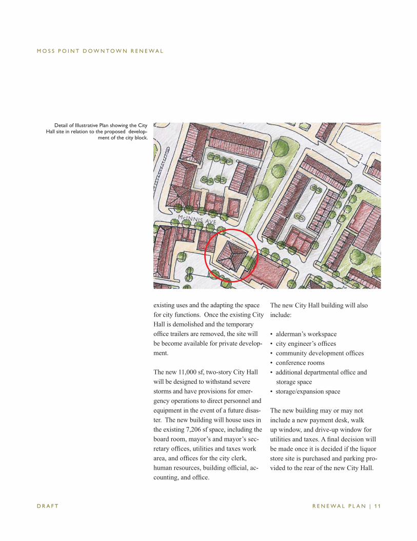
The site for the new City Hall is on the south side of McInnis Avenue midway between Main Street and Morris Street. The site overlooks a new public green which bisects the city-owned block and connects the site to Denny Street and the riverfront. The site is currently owned by the city and can accommodate a new 2-story building with space for consoli-dated city offi ces and a modest amount of expansion space. In the short term and until development occurs parking
can be accommodated on the city-owned block. Should the City decided to pur-chase the site of the existing liquor store; parking may be provided to the rear of the building with driveway access from Morris Street and potentially from Main Street.
Several alternative sites and development options were evaluated during the plan-ning process, including the construction of new buildings at the southeast corner of McInnis Avenue and Main Street and the adaptive reuse of the Scruggs Center. The site at the corner of McInnis Avenue was dismissed because of its high vis-ibility, private ownership, and potential for successful retail use. The adaptive reuse of the Scruggs Center site was not favored because of its relatively small size and anticipated challenges relocating
M O S S P O I N T D O W N T O W N R E N E W A L
R E N E W A L P L A N | 1 1 D R A F T
Detail of Illustrative Plan showing the City Hall site in relation to the proposed develop-
ment of the city block.
existing uses and the adapting the space for city functions. Once the existing City Hall is demolished and the temporary offi ce trailers are removed, the site will be become available for private develop-ment.
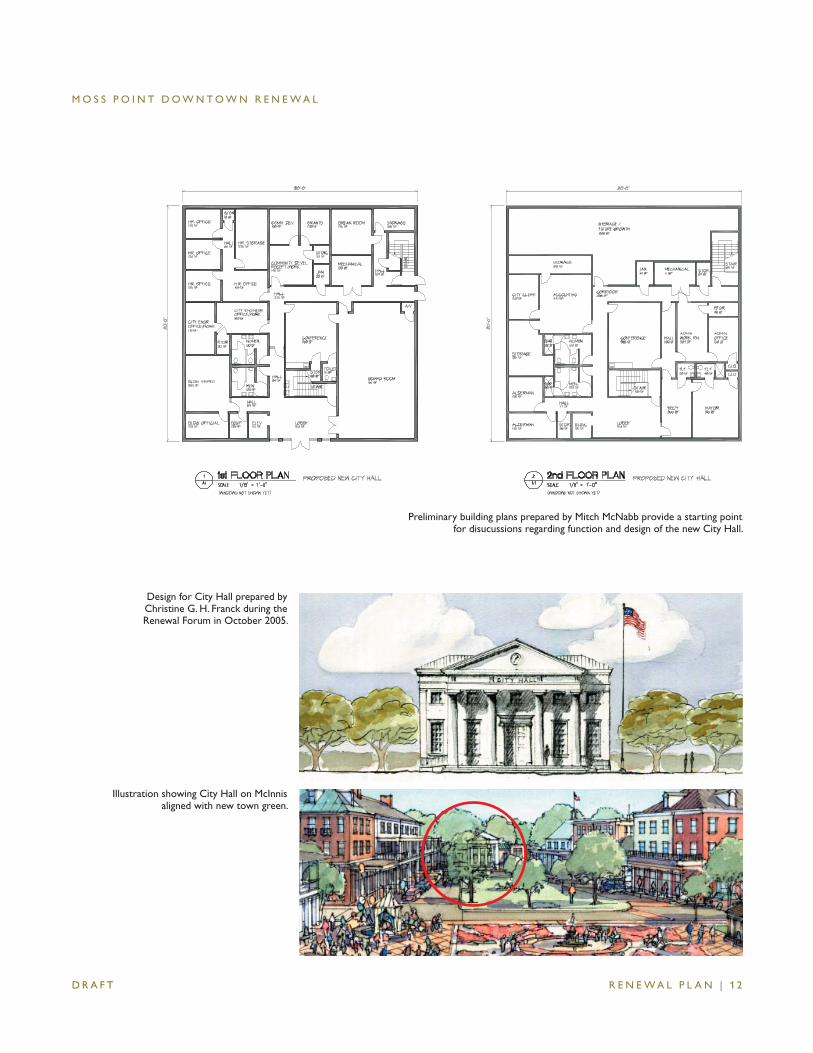
The new 11,000 sf, two-story City Hall will be designed to withstand severe storms and have provisions for emer-gency operations to direct personnel and equipment in the event of a future disas-ter. The new building will house uses in the existing 7,206 sf space, including the board room, mayor’s and mayor’s sec-retary offi ces, utilities and taxes work area, and offi ces for the city clerk, human resources, building offi cial, ac-counting, and offi ce.
The new City Hall building will also include:
• alderman’s workspace• city engineer’s offi ces• community development offi ces• conference rooms• additional departmental offi ce and
storage space • storage/expansion space
The new building may or may not include a new payment desk, walk up window, and drive-up window for utilities and taxes. A fi nal decision will be made once it is decided if the liquor store site is purchased and parking pro-vided to the rear of the new City Hall.
M O S S P O I N T D O W N T O W N R E N E W A L
R E N E W A L P L A N | 1 2 D R A F T
Illustration showing City Hall on McInnis aligned with new town green.
Design for City Hall prepared by Christine G. H. Franck during the Renewal Forum in October 2005.
Preliminary building plans prepared by Mitch McNabb provide a starting point for disucussions regarding function and design of the new City Hall.
M O S S P O I N T D O W N T O W N R E N E W A L
R E N E W A L P L A N | 1 3 D R A F T
Central Fire Station
Under the plan, the existing Central Fire Station will be vacated and replaced by a new facility on the Belleview Shop-ping Center Site. The existing building’s small size, poor condition, outdated building systems, cramped living quar-ters, and location in the fl oodplain make any sort of adaptive reuse of the existing building—the former City Waterworks Building—or reconstruction on-site infeasible. The new building will have three fully-scaled apparatus bays, offi ce space for the Fire Chief, Inspector, and Fire Marshall; training and storage space; and quarters for on-duty personnel.
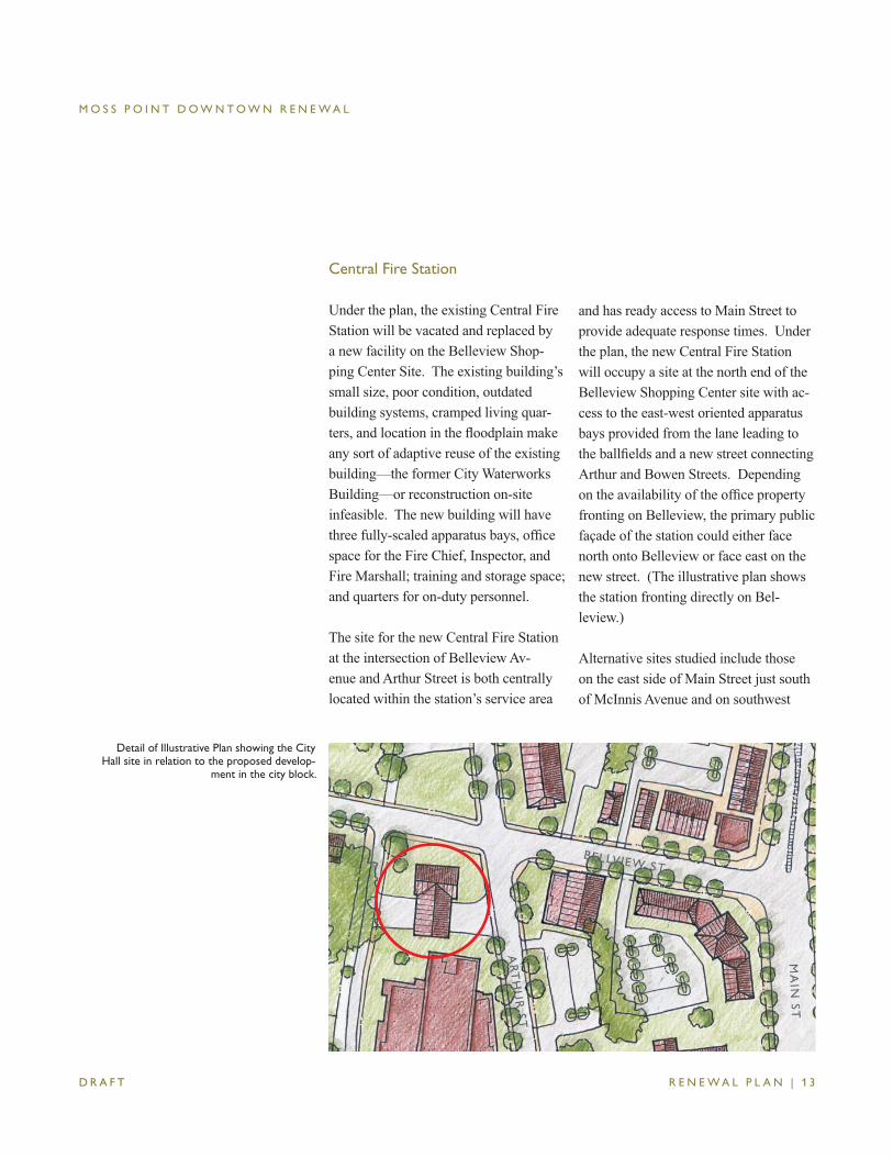
The site for the new Central Fire Station at the intersection of Belleview Av-enue and Arthur Street is both centrally located within the station’s service area
and has ready access to Main Street to provide adequate response times. Under the plan, the new Central Fire Station will occupy a site at the north end of the Belleview Shopping Center site with ac-cess to the east-west oriented apparatus bays provided from the lane leading to the ballfi elds and a new street connecting Arthur and Bowen Streets. Depending on the availability of the offi ce property fronting on Belleview, the primary public façade of the station could either face north onto Belleview or face east on the new street. (The illustrative plan shows the station fronting directly on Bel-leview.)
Alternative sites studied include those on the east side of Main Street just south of McInnis Avenue and on southwest
Detail of Illustrative Plan showing the City Hall site in relation to the proposed develop-
ment in the city block.
M O S S P O I N T D O W N T O W N R E N E W A L
R E N E W A L P L A N | 1 4 D R A F T
corner of McInnis Avenue and Morris Street. The Main Street site was consid-ered more appropriate for a mixed use building and the McInnis Avenue site is currently occupied by established retail businesses.
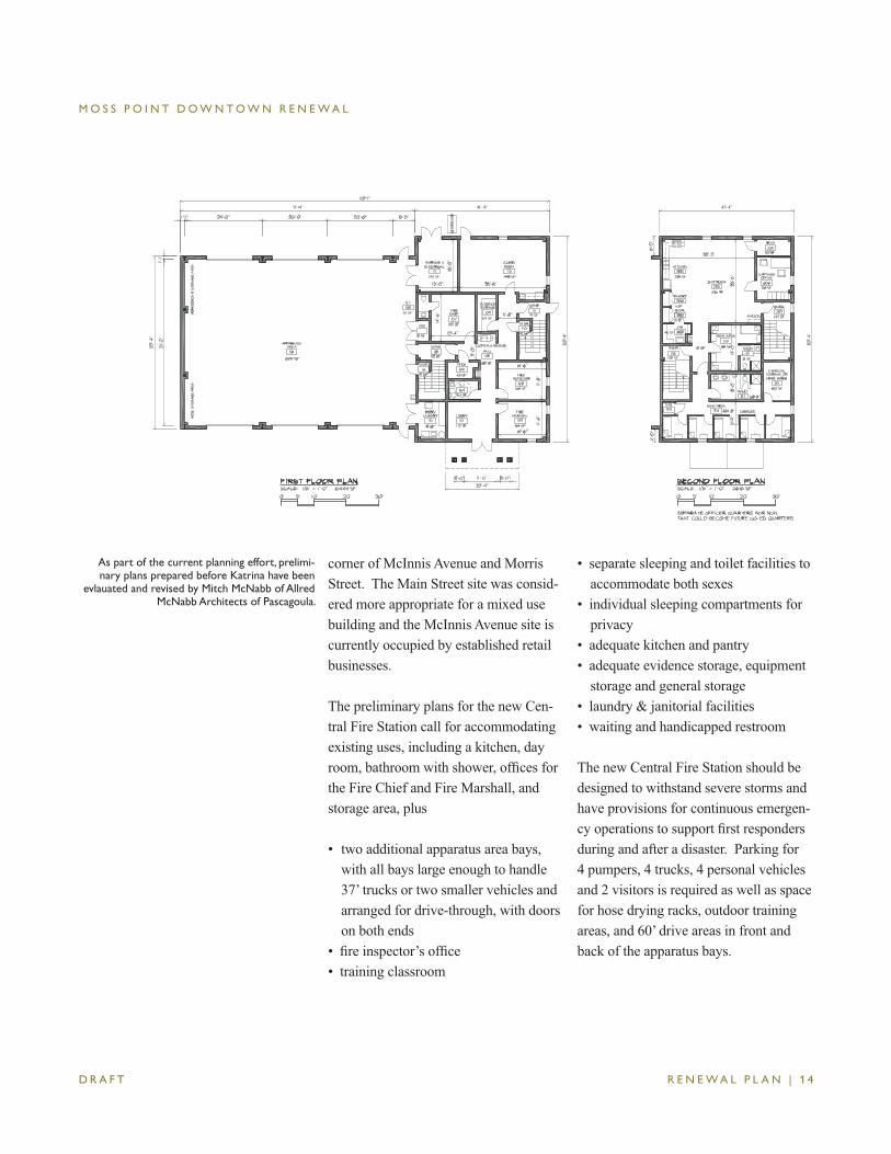
The preliminary plans for the new Cen-tral Fire Station call for accommodating existing uses, including a kitchen, day room, bathroom with shower, offi ces for the Fire Chief and Fire Marshall, and storage area, plus
• two additional apparatus area bays, with all bays large enough to handle 37’ trucks or two smaller vehicles and arranged for drive-through, with doors on both ends
• fi re inspector’s offi ce• training classroom
• separate sleeping and toilet facilities to accommodate both sexes
• individual sleeping compartments for privacy
• adequate kitchen and pantry• adequate evidence storage, equipment
storage and general storage• laundry & janitorial facilities• waiting and handicapped restroom
The new Central Fire Station should be designed to withstand severe storms and have provisions for continuous emergen-cy operations to support fi rst responders during and after a disaster. Parking for 4 pumpers, 4 trucks, 4 personal vehicles and 2 visitors is required as well as space for hose drying racks, outdoor training areas, and 60’ drive areas in front and back of the apparatus bays.
As part of the current planning effort, prelimi-nary plans prepared before Katrina have been
evlauated and revised by Mitch McNabb of Allred McNabb Architects of Pascagoula.
M O S S P O I N T D O W N T O W N R E N E W A L
R E N E W A L P L A N | 1 5 D R A F T
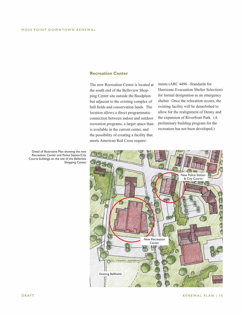
Recreation Center
The new Recreation Center is located at the south end of the Belleview Shop-ping Center site outside the fl oodplain but adjacent to the existing complex of ball fi elds and conservation lands. The location allows a direct programmatic connection between indoor and outdoor recreation programs, a larger space than is available in the current center, and the possibility of creating a facility that meets American Red Cross require-
ments (ARC 4496 –Standards for Hurricane Evacuation Shelter Selection) for formal designation as an emergency shelter. Once the relocation occurs, the existing facility will be demolished to allow for the realignment of Denny and the expansion of Riverfront Park. (A preliminary building program for the recreation has not been developed.)
Existing Ballfiields
Detail of Illustrative Plan showing the new Recreation Center and Police Station/City
Courts buildings on the site of the Belleview Shopping Center.
New Recreation Center
New Police Station & City Courts
M O S S P O I N T D O W N T O W N R E N E W A L
R E N E W A L P L A N | 1 6 D R A F T
Police Station & City Courts
The existing Police Station & City Court is located within a fl ood area in former mercantile buildings of questionable structural integrity. The new Police Station should be designed to withstand severe storms and have provisions for continuous emergency operations in order to direct emergency police, medi-cal and fi re responders during and after a disaster.
The existing 9,386 sf Police Station & City Court has:
• a small lobby and public toilets• city court room, judges offi ce, court
clerk offi ce and court records area• chief’s offi ce, deputy chief’s offi ce and
secretary’s offi ce• captain’s offi ce• detective’s offi ces• reserves offi ce, animal control and
warrant offi cer• briefi ng room• dispatch center• interview rooms• jail cells and jail support areas• police records clerk and storage room
• evidence storage• equipment storage and other types of
storage rooms• break room and kitchen• toilets, janitor’s space, etc.
The new Police Station & City Court should also include the following spaces:
• polygraph room and observation room• witness waiting room• sally port and additional jail cells• fi tness room, locker rooms and toilets
with showers• classroom and conference room• additional space for each department• larger lobby and courtroom
It is desired that the new Police Station be a two-story facility, which would ne-cessitate space for two stairs, an elevator and elevator equipment. The City Court and the jail can be one-story. Parking for 50 police department and employee ve-hicles, and 75 public vehicles is planned, as is covered parking for ATV’s and motorcycles and a fenced area for the storage of barricades.
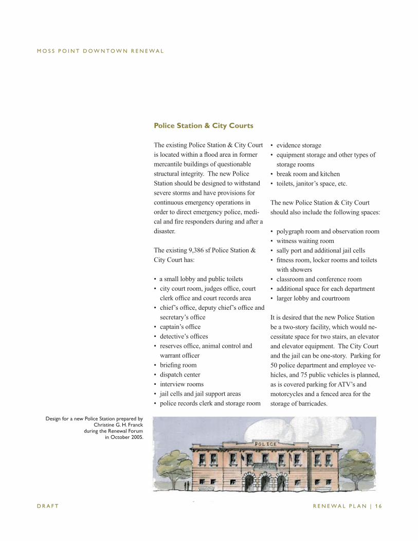
Design for a new Police Station prepared by Christine G. H. Franck
during the Renewal Forumin October 2005.
M O S S P O I N T D O W N T O W N R E N E W A L
R E N E W A L P L A N | 1 7 D R A F T
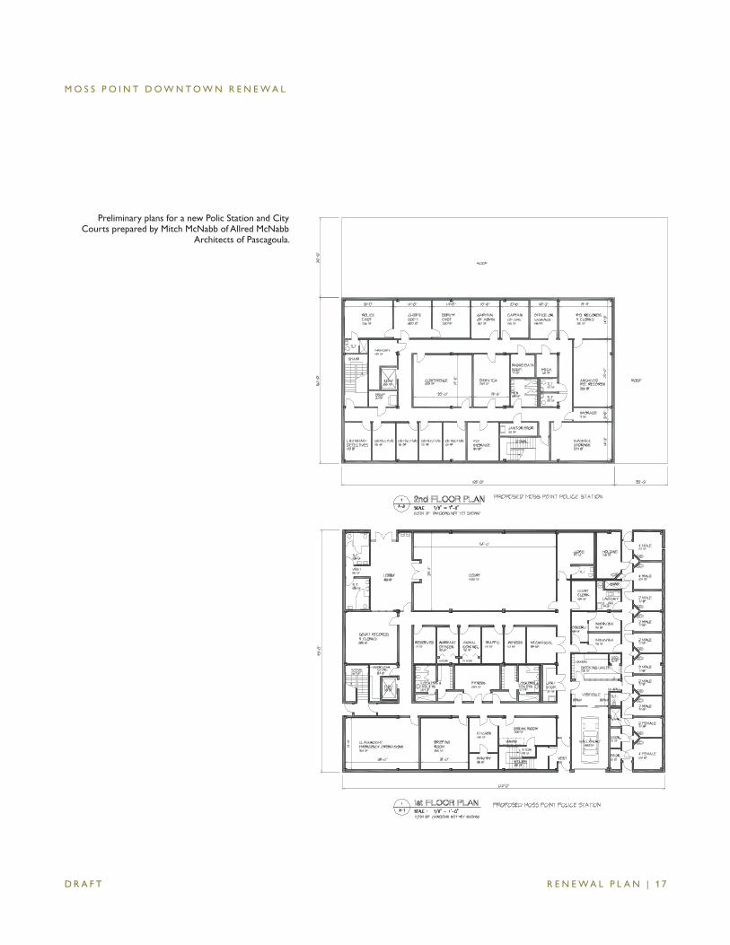
Preliminary plans for a new Polic Station and City Courts prepared by Mitch McNabb of Allred McNabb
Architects of Pascagoula.
M O S S P O I N T D O W N T O W N R E N E W A L
R E N E W A L P L A N | 1 8 D R A F T
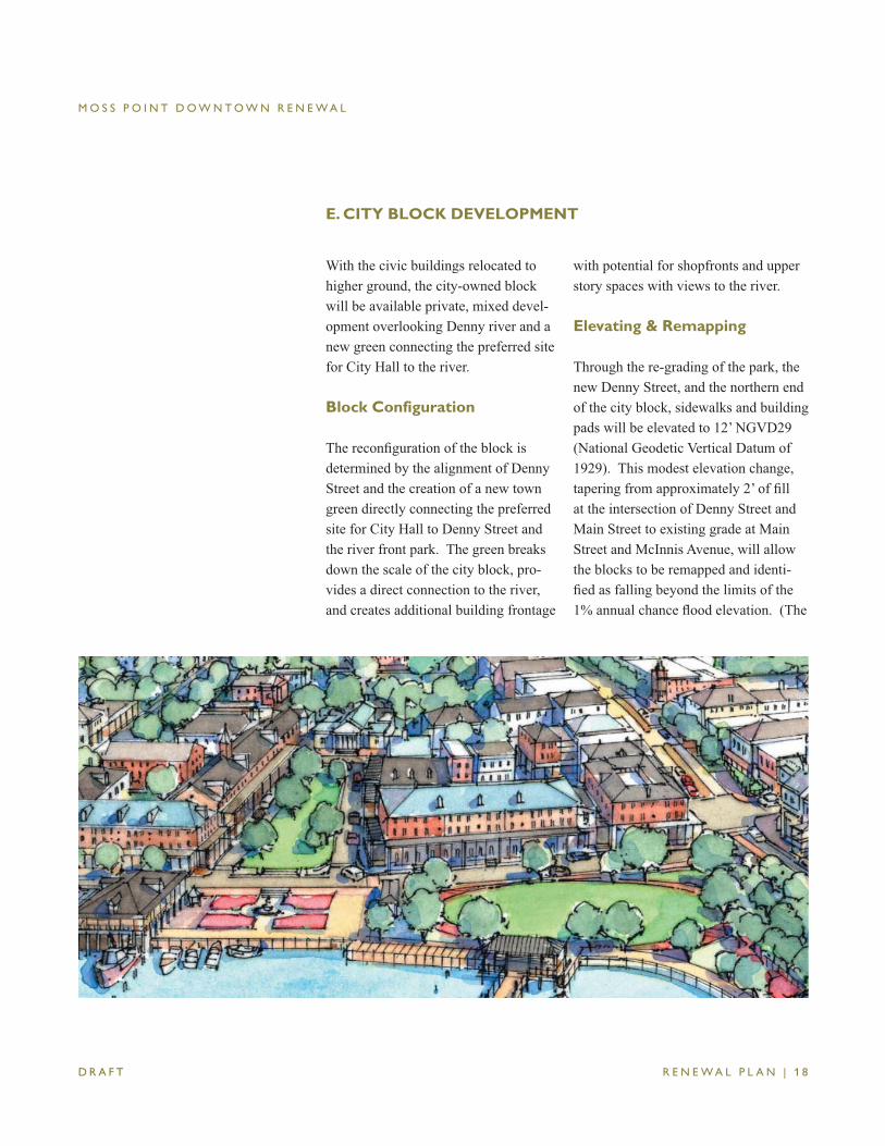
E. CITY BLOCK DEVELOPMENT
with potential for shopfronts and upper story spaces with views to the river.
Elevating & Remapping
Through the re-grading of the park, the new Denny Street, and the northern end of the city block, sidewalks and building pads will be elevated to 12’ NGVD29 (National Geodetic Vertical Datum of 1929). This modest elevation change, tapering from approximately 2’ of fi ll at the intersection of Denny Street and Main Street to existing grade at Main Street and McInnis Avenue, will allow the blocks to be remapped and identi-fi ed as falling beyond the limits of the 1% annual chance fl ood elevation. (The
With the civic buildings relocated to higher ground, the city-owned block will be available private, mixed devel-opment overlooking Denny river and a new green connecting the preferred site for City Hall to the river.
Block Configuration
The reconfi guration of the block is determined by the alignment of Denny Street and the creation of a new town green directly connecting the preferred site for City Hall to Denny Street and the river front park. The green breaks down the scale of the city block, pro-vides a direct connection to the river, and creates additional building frontage
M O S S P O I N T D O W N T O W N R E N E W A L
R E N E W A L P L A N | 1 9 D R A F T
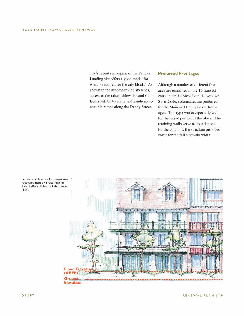
city’s recent remapping of the Pelican Landing site offers a good model for what is required for the city block.) As shown in the accompanying sketches, access to the raised sidewalks and shop-fronts will be by stairs and handicap ac-cessible ramps along the Denny Street.
Preferred Frontages
Although a number of different front-ages are permitted in the T5 transect zone under the Moss Point Downtown SmartCode, colonnades are preferred for the Main and Denny Street front-ages. This type works especially well for the raised portion of the block. The retaining walls serve as foundations for the columns, the structure provides cover for the full sidewalk width.
Flood Elevation (ABFE)GroundElevation
Preliminary sketches for downtown redevelopment by Bruce Tolar of Tolar LeBatard Denmark Architects, PLLC.
M O S S P O I N T D O W N T O W N R E N E W A L
R E N E W A L P L A N | 2 0 D R A F T
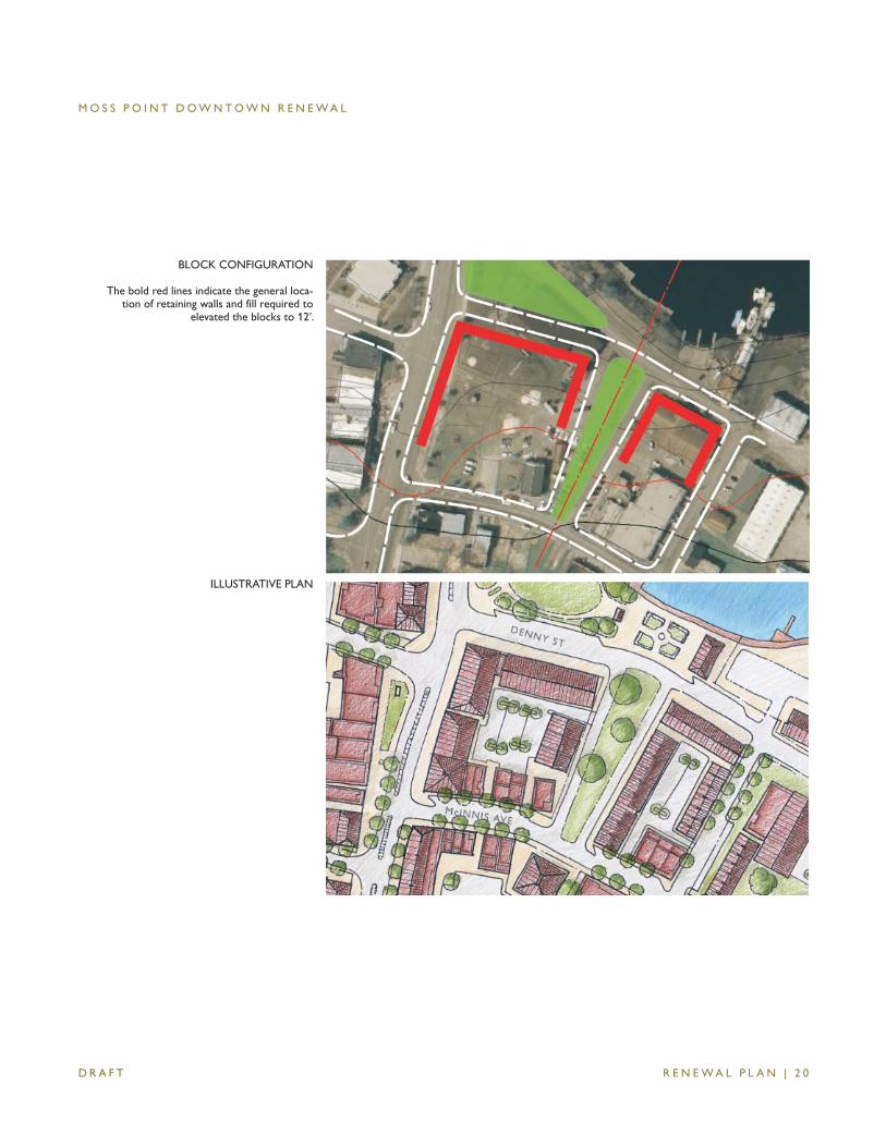
BLOCK CONFIGURATION
The bold red lines indicate the general loca-tion of retaining walls and fill required to
elevated the blocks to 12’.
ILLUSTRATIVE PLAN
M O S S P O I N T D O W N T O W N R E N E W A L
R E N E W A L P L A N | 2 1 D R A F T
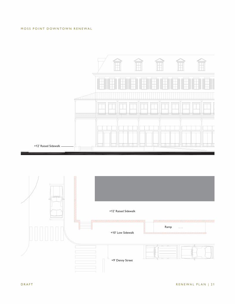
+12' Raised Sidewalk
+12' Raised Sidewalk
+10' Low Sidewalk
+9' Denny Street
Ramp
M O S S P O I N T D O W N T O W N R E N E W A L
R E N E W A L P L A N | 2 2 D R A F T
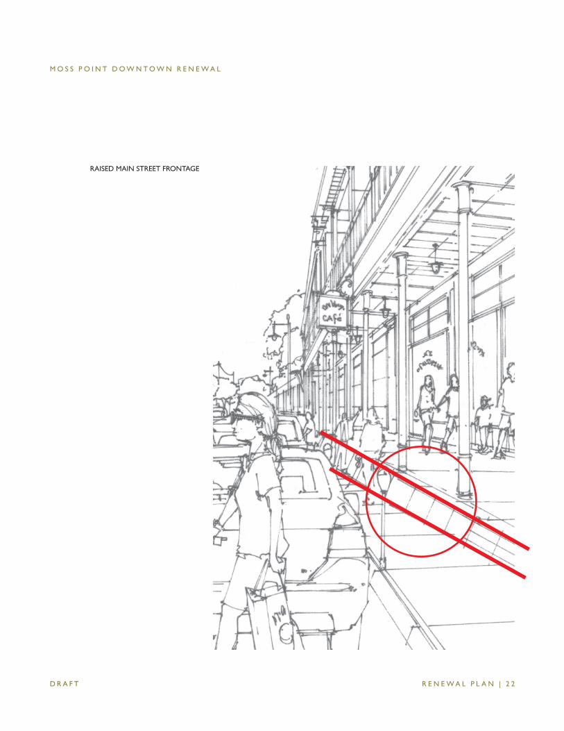
RAISED MAIN STREET FRONTAGE
M O S S P O I N T D O W N T O W N R E N E W A L
R E N E W A L P L A N | 2 3 D R A F T
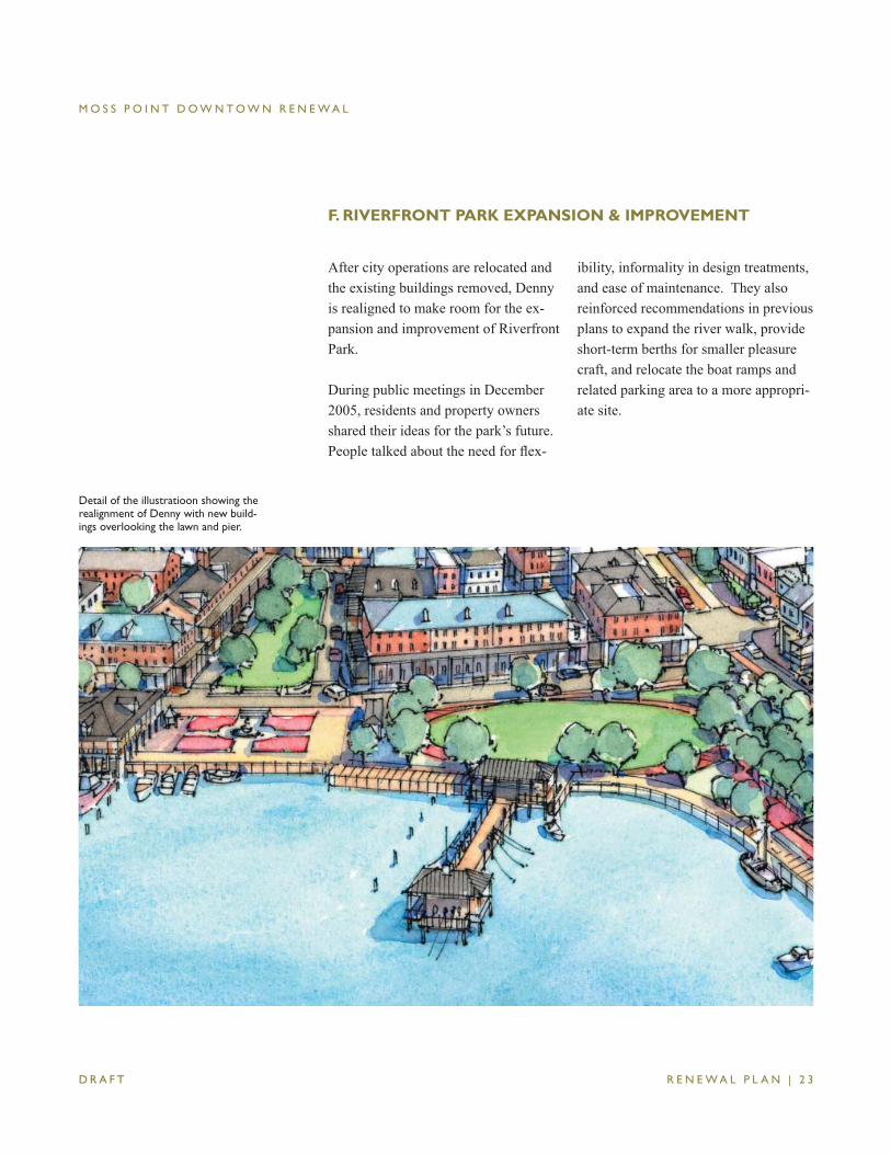
F. RIVERFRONT PARK EXPANSION & IMPROVEMENT
After city operations are relocated and the existing buildings removed, Denny is realigned to make room for the ex-pansion and improvement of Riverfront Park.
During public meetings in December 2005, residents and property owners shared their ideas for the park’s future. People talked about the need for fl ex-
ibility, informality in design treatments, and ease of maintenance. They also reinforced recommendations in previous plans to expand the river walk, provide short-term berths for smaller pleasure craft, and relocate the boat ramps and related parking area to a more appropri-ate site.
Detail of the illustratioon showing the realignment of Denny with new build-ings overlooking the lawn and pier.
M O S S P O I N T D O W N T O W N R E N E W A L
R E N E W A L P L A N | 2 4 D R A F T
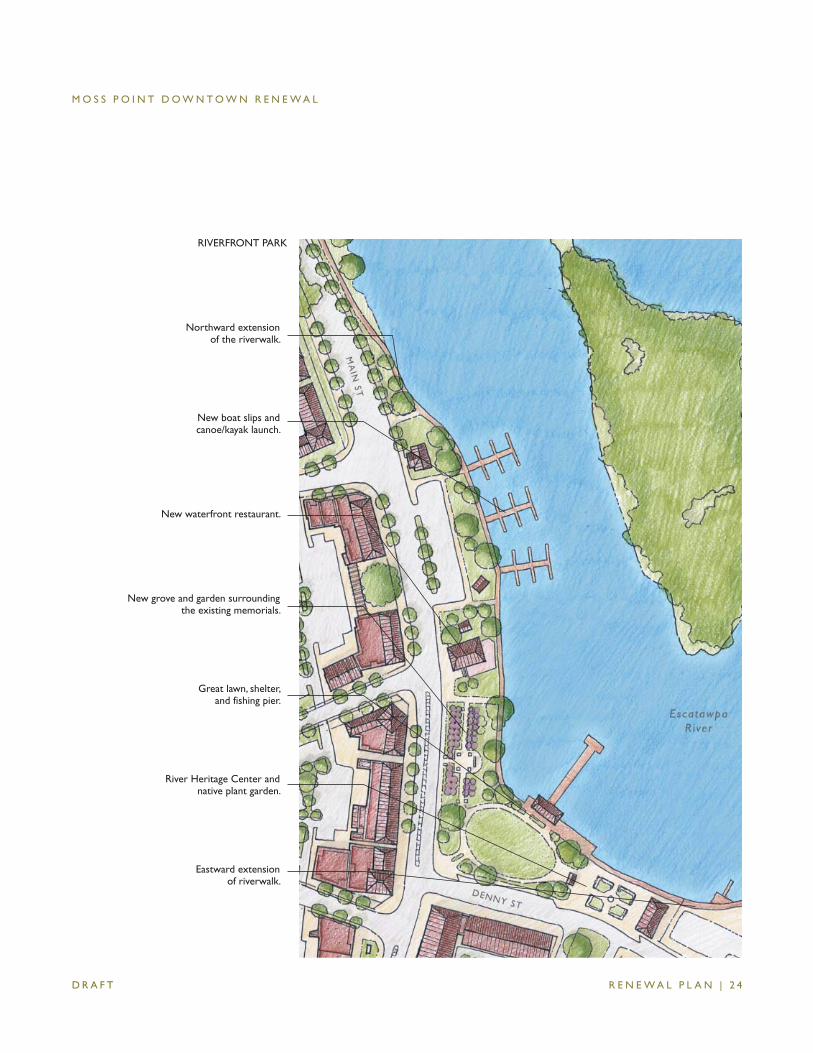
Great lawn, shelter, and fishing pier.
New grove and garden surrounding the existing memorials.
New waterfront restaurant.
New boat slips and canoe/kayak launch.
Northward extension of the riverwalk.
River Heritage Center and native plant garden.
Eastward extension of riverwalk.
RIVERFRONT PARK
M O S S P O I N T D O W N T O W N R E N E W A L
R E N E W A L P L A N | 2 5 D R A F T
Riverfront Park Concepts
Reviews of the concepts for the river-front park follow.
Central Lawn & Pier. At the corner of Denny and Main Street, an expansive grass area serves as a central gathering place for events and activities and opens onto a new shelter and pier extending into the river.
Memorial Grove. As a more fi tting setting for the existing memorials, a grove of fl owering trees are arranged along a newly created path of crushed shell or pea gravel. Benches along the path and ceremonial gates create a sense of enclosure and a peaceful place for remembrance and refl ection.
Waterfront Restaurant & Boat Slips. To the north of the grove, a site is reserved for a small, 5-6,000 square foot restaurant with outdoor seating overlooking the river walk. Parking for the restaurant is providing in the exist-ing lot to the north. New docks provide transient berths for daytime visits and overnight stays. The existing buildings are concerted for use as small shops, dock master or river keeper offi ces, or canoe or kayak rental operation.
River Heritage Center & Garden. At the east of the park, space is reserved for a new building housing exhibit and event space and a native plant or water garden and fountain.
Riverwalk Extension. Tying the spaces together is the existing river walk and its northward and eastward ex-tensions. As defi ned in the Waterfront plan, the existing river walk will extend northward to the bridge and new marina and commercial uses and eastward through the new marina and Mississippi Export property. Ultimately, this sec-tion will link the Kreole neighborhood with the new development in the IP site to the river and downtown.
Sustainable Design. Sustainability will be a central concern as the design process moves forward. Opportunities for harvesting and fi ltering storm water runoff; incorporating native, drought and fl ood tolerant plantings; and incorporating sustainably sourced and constructed materials will be explored as more detailed plans are prepared.
M O S S P O I N T D O W N T O W N R E N E W A L
R E N E W A L P L A N | 2 6 D R A F T
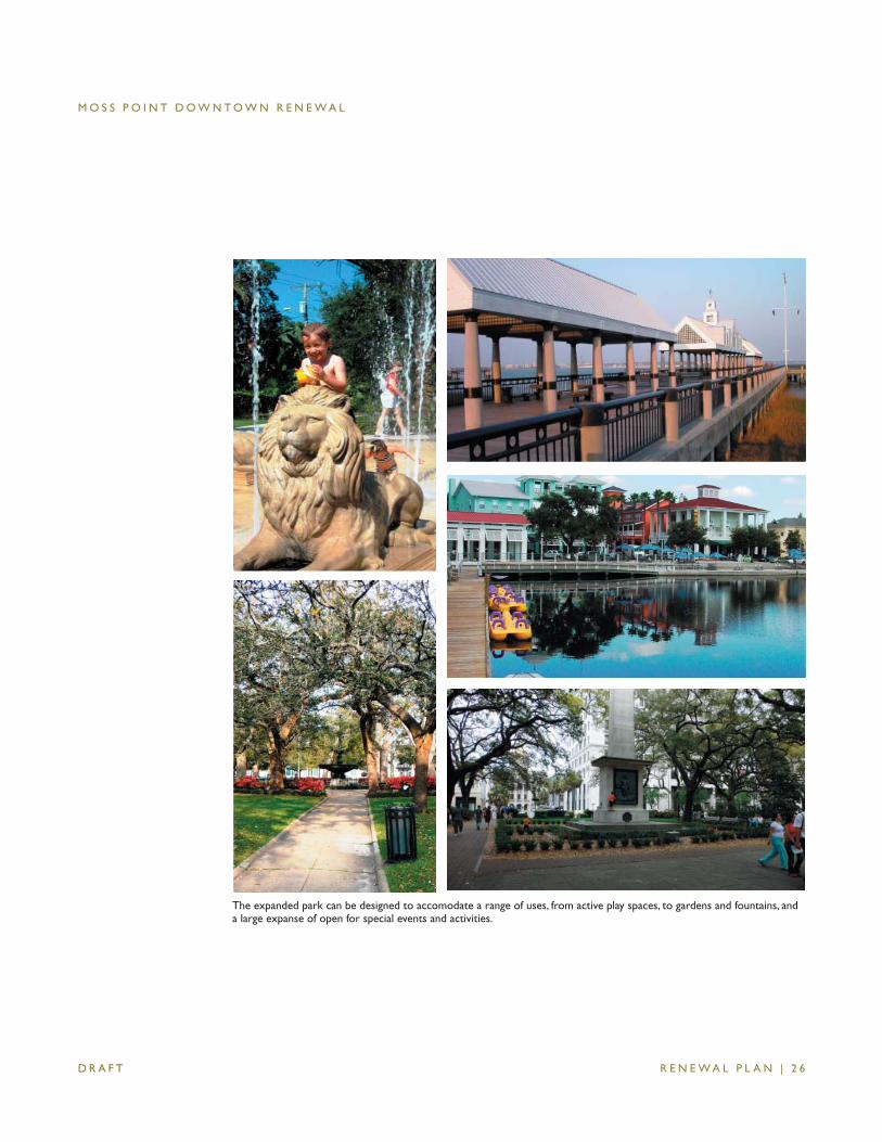
The expanded park can be designed to accomodate a range of uses, from active play spaces, to gardens and fountains, and a large expanse of open for special events and activities.
M O S S P O I N T D O W N T O W N R E N E W A L
R E N E W A L P L A N | 2 7 D R A F T
G. THOROUGHFARE IMPROVEMENTS
speeds; on-street parallel parking; and suffi cient capacity to accommodate existing traffi c volumes and serve ef-fectively as an evacuation route.
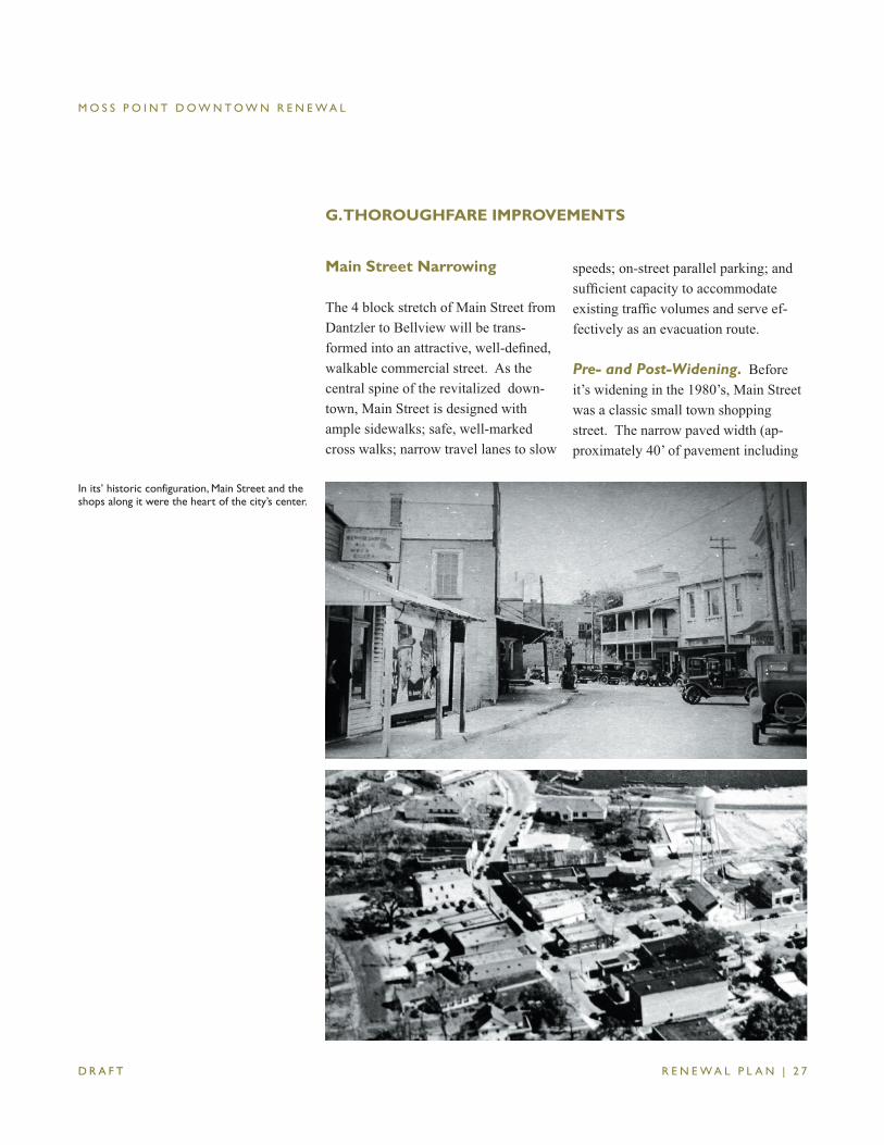
Pre- and Post-Widening. Before it’s widening in the 1980’s, Main Street was a classic small town shopping street. The narrow paved width (ap-proximately 40’ of pavement including
In its’ historic configuration, Main Street and the shops along it were the heart of the city’s center.
Main Street Narrowing
The 4 block stretch of Main Street from Dantzler to Bellview will be trans-formed into an attractive, well-defi ned, walkable commercial street. As the central spine of the revitalized down-town, Main Street is designed with ample sidewalks; safe, well-marked cross walks; narrow travel lanes to slow
M O S S P O I N T D O W N T O W N R E N E W A L
R E N E W A L P L A N | 2 8 D R A F T
on-street parking) moderated travel speeds and allowed for easy crossings. Sidewalks were modest but adequate. One to four-story buildings with ground fl oor shops and upper story apartments and small offi ces contributed activity and spatial defi nition. A mix of awn-ings, galleries, and canopies shaded the streets and provided cover from the rain. Even the bend in the road at the river defl ected views and contributed to the feeling of entry and enclosure.
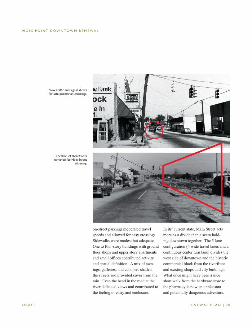
In its’ current state, Main Street acts more as a divide than a seam hold-ing downtown together. The 5-lane confi guration (4 wide travel lanes and a continuous center turn lane) divides the west side of downtown and the historic commercial block from the riverfront and existing shops and city buildings. What once might have been a nice short walk from the hardware store to the pharmacy is now an unpleasant and potentially dangerous adventure.
Slow traffic and signal allows for safe pedestrian crossings.
Location of storefronts removed for Main Street
widening.
M O S S P O I N T D O W N T O W N R E N E W A L
R E N E W A L P L A N | 2 9 D R A F T
High travel speeds, wide lane widths, the lack of spatial defi nition, and the new, straight alignment make crossing diffi cult and a walk along Main Street particularly unattractive.
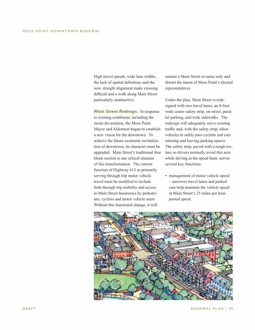
Main Street Redesign. In response to existing conditions, including the storm devastation, the Moss Point Mayor and Aldermen began to establish a new vision for the downtown. To achieve the future economic revitaliza-tion of downtown, its character must be upgraded. Main Street’s traditional four block section is one critical element of this transformation. The current function of Highway 613 as primarily serving through trip motor vehicle travel must be modifi ed to include both through trip mobility and access to Main Street businesses by pedestri-ans, cyclists and motor vehicle users. Without this functional change, it will
remain a Main Street in name only and thwart the intent of Moss Point’s elected representatives.
Under the plan, Main Street is rede-signed with two travel lanes, an 8-foot wide center safety strip, on-street, paral-lel parking, and wide sidewalks. The redesign will adequately serve existing traffi c and, with the safety strip, allow vehicles to safely pass cyclists and cars entering and leaving parking spaces. The safety strip, paved with a rough tex-ture so drivers normally avoid this area while driving at the speed limit, serves several key functions:
• management of motor vehicle speed – narrower travel lanes and parked cars help maintain the vehicle speed at Main Street’s 25 miles per hour posted speed.
M O S S P O I N T D O W N T O W N R E N E W A L
R E N E W A L P L A N | 3 0 D R A F T
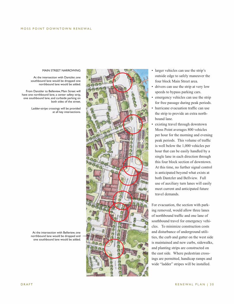
• larger vehicles can use the strip’s outside edge to safely maneuver the four block Main Street area.
• drivers can use the strip at very low speeds to bypass parking cars.
• emergency vehicles can use the strip for free passage during peak periods.
• hurricane evacuation traffi c can use the strip to provide an extra north-bound lane.
• existing travel through downtown Moss Point averages 800 vehicles per hour for the morning and evening peak periods. This volume of traffi c is well below the 1,000 vehicles per hour that can be easily handled by a single lane in each direction through this four block section of downtown. At this time, no further signal control is anticipated beyond what exists at both Dantzler and Bellview. Full use of auxiliary turn lanes will easily meet current and anticipated future travel demands.
For evacuation, the section with park-ing removed, would allow three lanes of northbound traffi c and one lane of southbound travel for emergency vehi-cles. To minimize construction costs and disturbance of underground utili-ties, the curb and gutter on the west side is maintained and new curbs, sidewalks, and planting strips are constructed on the east side. Where pedestrian cross-ings are permitted, handicap ramps and wide “ladder” stripes will be installed.
MAIN STREET NARROWING
At the intersection with Dantzler, one southbound lane would be dropped one
northbound lane would be added.
From Danztler to Belleview, Main Street will have one northbound lane, a center safety strip, one southbound lane, and curbside parking on
both sides of the street.
Ladder-stripe crossings will be providedat all key intersections.
At the intersection with Belleview, one northbound lane would be dropped and
one southbound lane would be added.
M O S S P O I N T D O W N T O W N R E N E W A L
R E N E W A L P L A N | 3 1 D R A F T
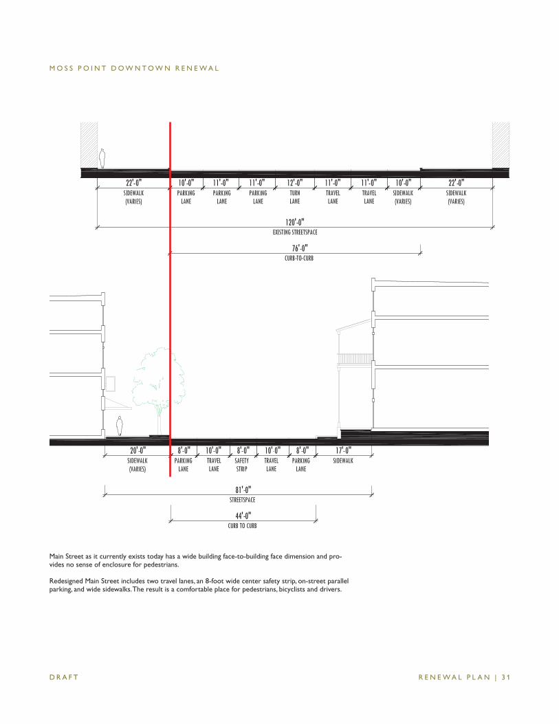
Main Street as it currently exists today has a wide building face-to-building face dimension and pro-vides no sense of enclosure for pedestrians.
Redesigned Main Street includes two travel lanes, an 8-foot wide center safety strip, on-street parallel parking, and wide sidewalks. The result is a comfortable place for pedestrians, bicyclists and drivers.
M O S S P O I N T D O W N T O W N R E N E W A L
R E N E W A L P L A N | 3 2 D R A F T
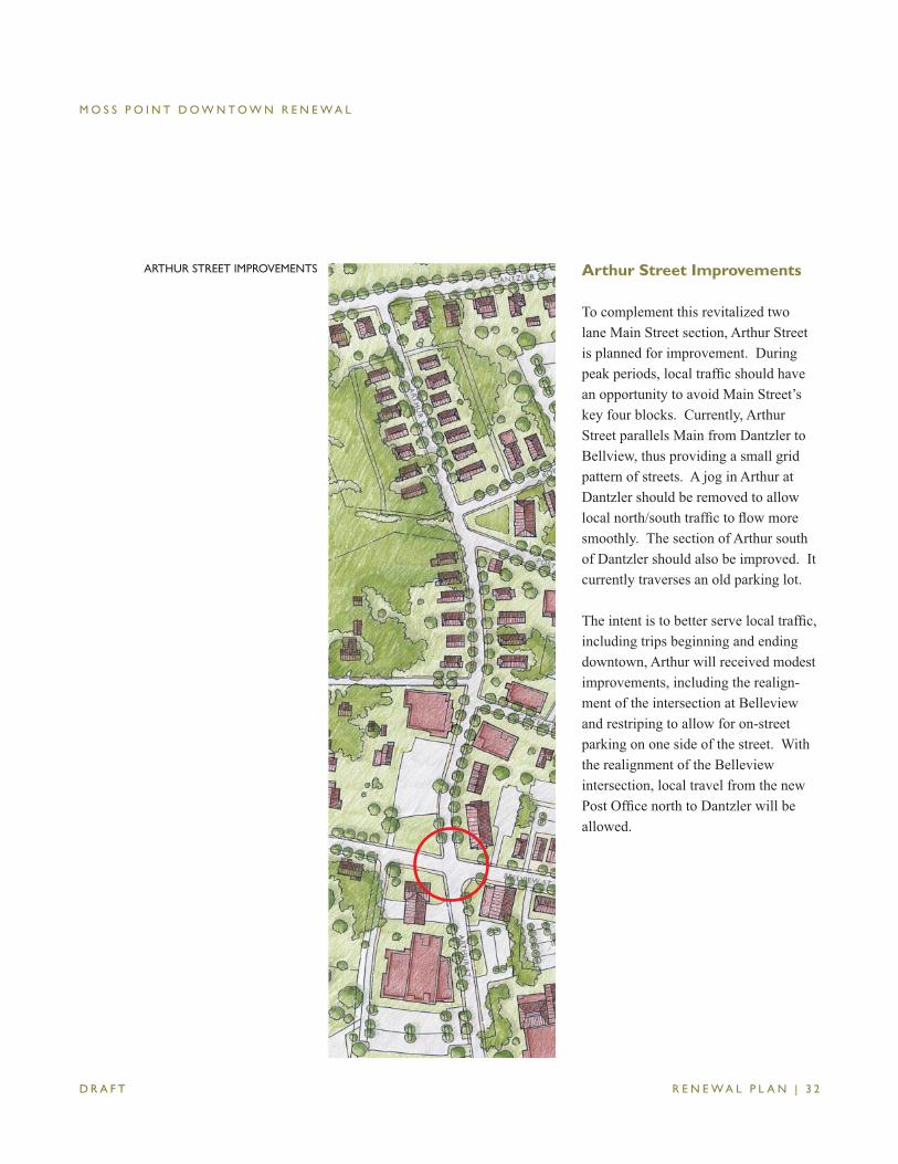
Arthur Street Improvements
To complement this revitalized two lane Main Street section, Arthur Street is planned for improvement. During peak periods, local traffi c should have an opportunity to avoid Main Street’s key four blocks. Currently, Arthur Street parallels Main from Dantzler to Bellview, thus providing a small grid pattern of streets. A jog in Arthur at Dantzler should be removed to allow local north/south traffi c to fl ow more smoothly. The section of Arthur south of Dantzler should also be improved. It currently traverses an old parking lot.
The intent is to better serve local traffi c, including trips beginning and ending downtown, Arthur will received modest improvements, including the realign-ment of the intersection at Belleview and restriping to allow for on-street parking on one side of the street. With the realignment of the Belleview intersection, local travel from the new Post Offi ce north to Dantzler will be allowed.
ARTHUR STREET IMPROVEMENTS
M O S S P O I N T D O W N T O W N R E N E W A L
R E N E W A L P L A N | 3 3 D R A F T
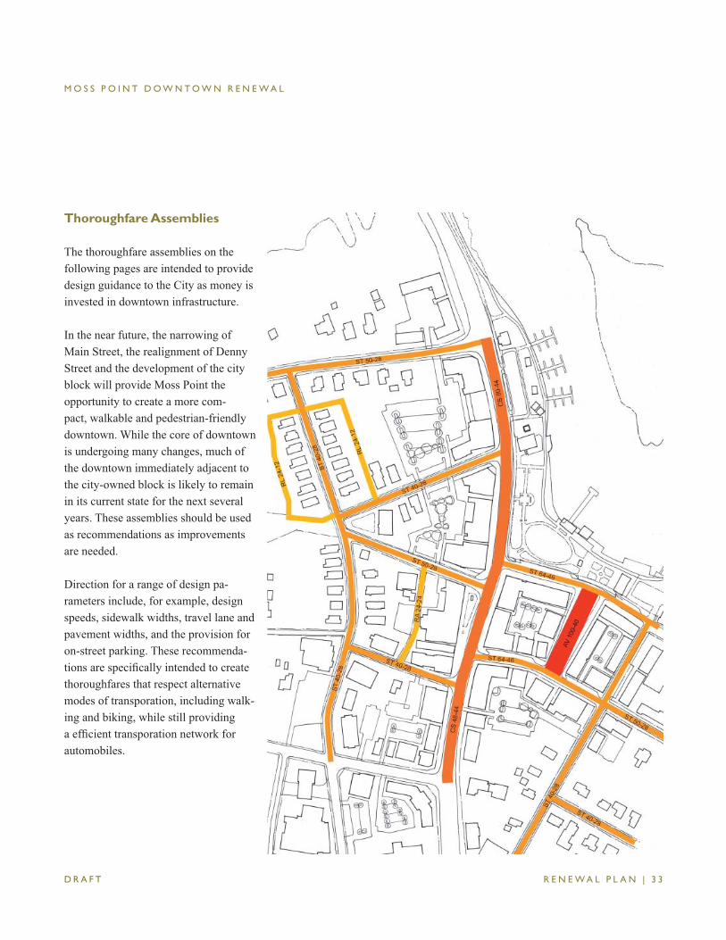
Thoroughfare Assemblies
The thoroughfare assemblies on the following pages are intended to provide design guidance to the City as money is invested in downtown infrastructure.
In the near future, the narrowing of Main Street, the realignment of Denny Street and the development of the city block will provide Moss Point the opportunity to create a more com-pact, walkable and pedestrian-friendly downtown. While the core of downtown is undergoing many changes, much of the downtown immediately adjacent to the city-owned block is likely to remain in its current state for the next several years. These assemblies should be used as recommendations as improvements are needed.
Direction for a range of design pa-rameters include, for example, design speeds, sidewalk widths, travel lane and pavement widths, and the provision for on-street parking. These recommenda-tions are specifi cally intended to create thoroughfares that respect alternative modes of transporation, including walk-ing and biking, while still providing a effi cient transporation network for automobiles.
M O S S P O I N T D O W N T O W N R E N E W A L
R E N E W A L P L A N | 3 4 D R A F T
Thoroughfare TypeTransect Zone Assignment
Right-of-Way WidthPavement Width
MovementDesign Speed
Pedestrian Crossing Time Traffi c Lanes
Parking LanesCurb Radius
Public Frontage Type Walkway Type
Planter Type Curb Type
Landscape TypeTransportation Provision
Thoroughfare Type
Right of Way Width
Pavement Width
Transportation
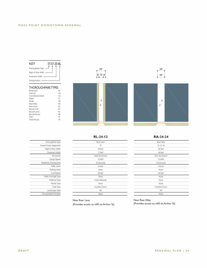
THOROUGHFARE TYPESBoulevard: BVAvenue: AVCommercial Street: CSStreet: STRoad: RDRear Alley: RARear Lane: RLBicycle Trail: BTBicycle Lane: BLBicycle Route: BRPath: PTTransit Route: TR
ST-57-20-BLKEY
24’
24’
24’
12’ 6’6’
Rear AlleyT6, T5, T424 feet 24 feet
Slow Movement10 MPH
3.5 seconds2 lanesNone
25 feetNoneNoneNone
Inverted CrownNA
None
RA-24-24Rear Lane
T324 feet 12 feet
Yield Movement10 MPH
2.0 seconds2 lanesNone
25 feetNone
6 feet SidewalkNone
Inverted CrownNA
None
RL-24-12
New Rear Lane
(Provides access to infill on Arthur St)
New Rear Alley (Provides access to infill on Arthur St)
M O S S P O I N T D O W N T O W N R E N E W A L
R E N E W A L P L A N | 3 5 D R A F T
Thoroughfare TypeTransect Zone Assignment
Right-of-Way WidthPavement Width
MovementDesign Speed
Pedestrian Crossing Time Traffi c Lanes
Parking LanesCurb Radius
Public Frontage Type Walkway Type
Planter Type Curb Type
Landscape TypeTransportation Provision
Thoroughfare Type
Right of Way Width
Pavement Width
Transportation
THOROUGHFARE TYPESBoulevard: BVAvenue: AVCommercial Street: CSStreet: STRoad: RDRear Alley: RARear Lane: RLBicycle Trail: BTBicycle Lane: BLBicycle Route: BRPath: PTTransit Route: TR
ST-57-20-BLKEY
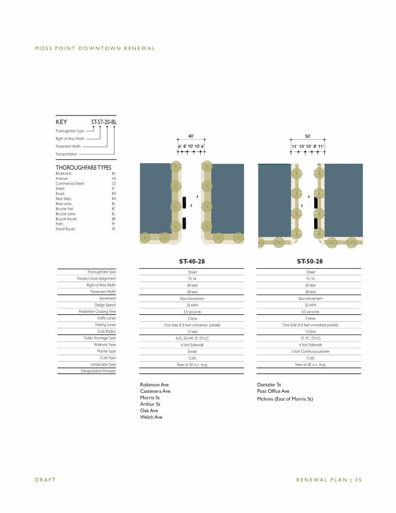
ST-40-28
StreetT5, T4
40 feet28 feet
Slow Movement25 MPH
3.5 seconds2 lane
One Side @ 8 feet unmarked parallel15 feet
A/G, SF/AW, ST, DY/LC6 foot Sidewalk
SwaleCurb
Trees at 30' o.c. Avg.
StreetT5, T4
50 feet 28 feet
Slow Movement25 MPH
4.0 seconds2 lanes
One Side @ 8 feet unmarked parallel15 feet
ST, FC, DY/LC 6 foot Sidewalk
5 foot Continuous planterCurb
Trees at 30' o.c. Avg.
ST-50-28
11’ 10’ 10’ 8’
50’
11’6’ 8’ 10’ 10’
40’
6’
Robinson AveCastenera AveMorris StArthur StOak AveWelch Ave
Dantzler StPost Office Ave
McInnis (East of Morris St)
M O S S P O I N T D O W N T O W N R E N E W A L
R E N E W A L P L A N | 3 6 D R A F T
Thoroughfare TypeTransect Zone Assignment
Right-of-Way WidthPavement Width
MovementDesign Speed
Pedestrian Crossing Time Traffi c Lanes
Parking LanesCurb Radius
Public Frontage Type Walkway Type
Planter Type Curb Type
Landscape TypeTransportation Provision
Thoroughfare Type
Right of Way Width
Pavement Width
Transportation
THOROUGHFARE TYPESBoulevard: BVAvenue: AVCommercial Street: CSStreet: STRoad: RDRear Alley: RARear Lane: RLBicycle Trail: BTBicycle Lane: BLBicycle Route: BRPath: PTTransit Route: TR
ST-57-20-BLKEY
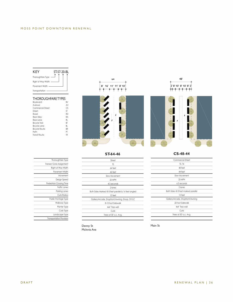
StreetT5
64 feet 46 feet
Slow Movement25 MPH
4.5 seconds2 lanes
Both Sides Marked @ 8 feet parallel & 16 feet angled15 feet
Gallery/Arcade, Shopfront/Awning, Stoop, DY/LC8-10 foot Sidewalk
4x4’ Tree wellCurb
Trees at 30' o.c. Avg.
ST-64-46
Denny StMcInnis Ave
64’
10’8’ 16’ 11’ 11’ 8’
CS-48-44
Commercial StreetT5, T4
48 feet44 feet
Slow Movement25 MPH
6.5 seconds2 lanes
Both Sides @ 8 feet marked parallel15 feet
Gallery/Arcade, Shopfront/Awning20 foot Sidewalk
4x4’ Tree wellCurb
Trees at 30' o.c. Avg.
48’
2’2’ 8’8’ 8’10’ 10’
Main St
M O S S P O I N T D O W N T O W N R E N E W A L
R E N E W A L P L A N | 3 7 D R A F T
Thoroughfare TypeTransect Zone Assignment
Right-of-Way WidthPavement Width
MovementDesign Speed
Pedestrian Crossing Time Traffi c Lanes
Parking LanesCurb Radius
Public Frontage Type Walkway Type
Planter Type Curb Type
Landscape TypeTransportation Provision
Thoroughfare Type
Right of Way Width
Pavement Width
Transportation
THOROUGHFARE TYPESBoulevard: BVAvenue: AVCommercial Street: CSStreet: STRoad: RDRear Alley: RARear Lane: RLBicycle Trail: BTBicycle Lane: BLBicycle Route: BRPath: PTTransit Route: TR
ST-57-20-BLKEY
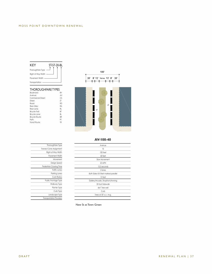
AvenueT5
100 feet 40 feet
Slow Movement25 MPH
12.0 seconds2 lanes
Both Sides @ 8 feet marked parallel15 feet
Gallery/Arcade, Shopfront/Awning20 foot Sidewalk
4x4’ Tree wellCurb
Trees at 30' o.c. Avg.
AV-100-40
100’
20’20’ 8’8’ Varies12’ 12’
New St at Town Green
M O S S P O I N T D O W N T O W N R E N E W A L
R E N E W A L P L A N | 3 8 D R A F T
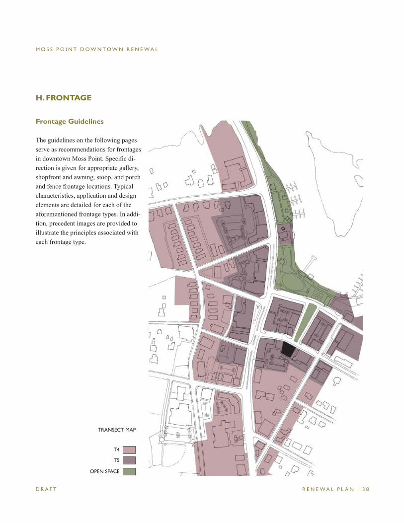
H. FRONTAGE
TRANSECT MAP
T4
T5
OPEN SPACE
Frontage Guidelines
The guidelines on the following pages serve as recommendations for frontages in downtown Moss Point. Specifi c di-rection is given for appropriate gallery, shopfront and awning, stoop, and porch and fence frontage locations. Typical characteristics, application and design elements are detailed for each of the aforementioned frontage types. In addi-tion, precedent images are provided to illustrate the principles associated with each frontage type.
M O S S P O I N T D O W N T O W N R E N E W A L
R E N E W A L P L A N | 3 9 D R A F T
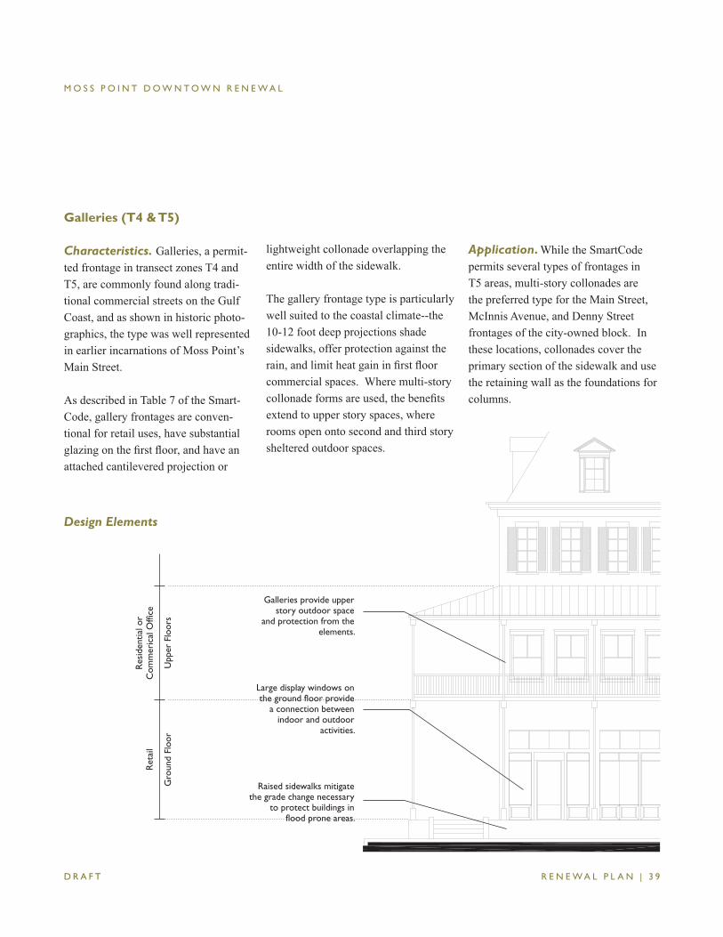
Galleries (T4 & T5)
Characteristics. Galleries, a permit-ted frontage in transect zones T4 and T5, are commonly found along tradi-tional commercial streets on the Gulf Coast, and as shown in historic photo-graphics, the type was well represented in earlier incarnations of Moss Point’s Main Street.
As described in Table 7 of the Smart-Code, gallery frontages are conven-tional for retail uses, have substantial glazing on the fi rst fl oor, and have an attached cantilevered projection or
lightweight collonade overlapping the entire width of the sidewalk.
The gallery frontage type is particularly well suited to the coastal climate--the 10-12 foot deep projections shade sidewalks, offer protection against the rain, and limit heat gain in fi rst fl oor commercial spaces. Where multi-story collonade forms are used, the benefi ts extend to upper story spaces, where rooms open onto second and third story sheltered outdoor spaces.
Design Elements
Application. While the SmartCode permits several types of frontages in T5 areas, multi-story collonades are the preferred type for the Main Street, McInnis Avenue, and Denny Street frontages of the city-owned block. In these locations, collonades cover the primary section of the sidewalk and use the retaining wall as the foundations for columns.
Galleries provide upper story outdoor space
and protection from the elements.
Gro
und
Floo
rU
pper
Flo
ors
Ret
ail
Res
iden
tial o
rC
omm
eric
al O
ffice
Large display windows on the ground floor provide
a connection between indoor and outdoor
activities.
Raised sidewalks mitigate the grade change necessary
to protect buildings in flood prone areas.
M O S S P O I N T D O W N T O W N R E N E W A L
R E N E W A L P L A N | 4 0 D R A F T
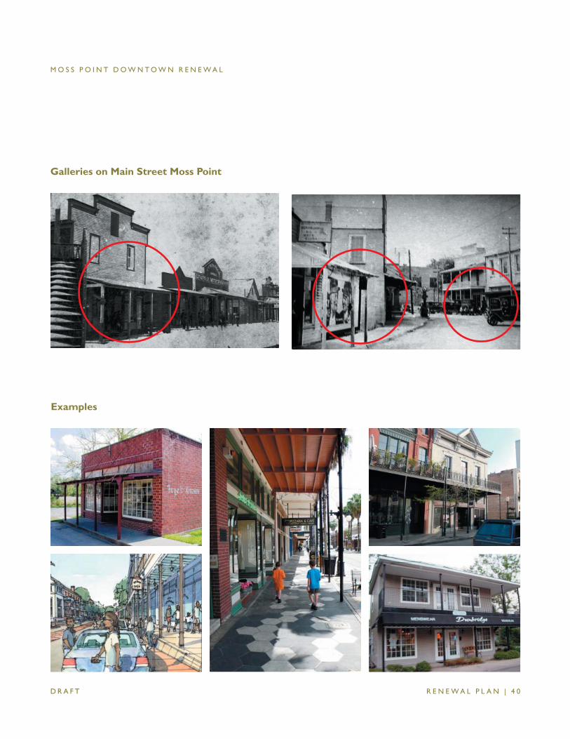
Galleries on Main Street Moss Point
Examples
M O S S P O I N T D O W N T O W N R E N E W A L
R E N E W A L P L A N | 4 1 D R A F T
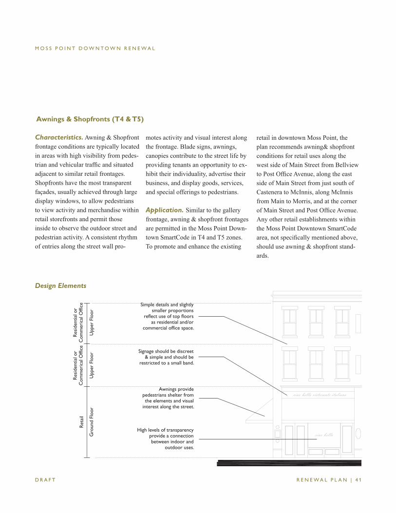
Awnings & Shopfronts (T4 & T5)
motes activity and visual interest along the frontage. Blade signs, awnings, canopies contribute to the street life by providing tenants an opportunity to ex-hibit their individuality, advertise their business, and display goods, services, and special offerings to pedestrians.
Application. Similar to the gallery frontage, awning & shopfront frontages are permitted in the Moss Point Down-town SmartCode in T4 and T5 zones. To promote and enhance the existing
retail in downtown Moss Point, the plan recommends awning& shopfront conditions for retail uses along the west side of Main Street from Bellview to Post Offi ce Avenue, along the east side of Main Street from just south of Castenera to McInnis, along McInnis from Main to Morris, and at the corner of Main Street and Post Offi ce Avenue. Any other retail establishments within the Moss Point Downtown SmartCode area, not specifi cally mentioned above, should use awning & shopfront stand-ards.
Simple details and slightly smaller proportions
reflect use of top floors as residential and/or
commercial office space.
Gro
und
Floo
rU
pper
Flo
or
Ret
ail
Res
iden
tial o
rC
omm
eric
al O
ffice Signage should be discreet
& simple and should be restricted to a small band.
High levels of transparency provide a connection between indoor and
outdoor uses.
Upp
er F
loor
Res
iden
tial o
rC
omm
eric
al O
ffice
Awnings provide pedestrians shelter from the elements and visual
interest along the street.
Design Elements
Characteristics. Awning & Shopfront frontage conditions are typically located in areas with high visibility from pedes-trian and vehicular traffi c and situated adjacent to similar retail frontages. Shopfronts have the most transparent façades, usually achieved through large display windows, to allow pedestrians to view activity and merchandise within retail storefronts and permit those inside to observe the outdoor street and pedestrian activity. A consistent rhythm of entries along the street wall pro-
M O S S P O I N T D O W N T O W N R E N E W A L
R E N E W A L P L A N | 4 2 D R A F T
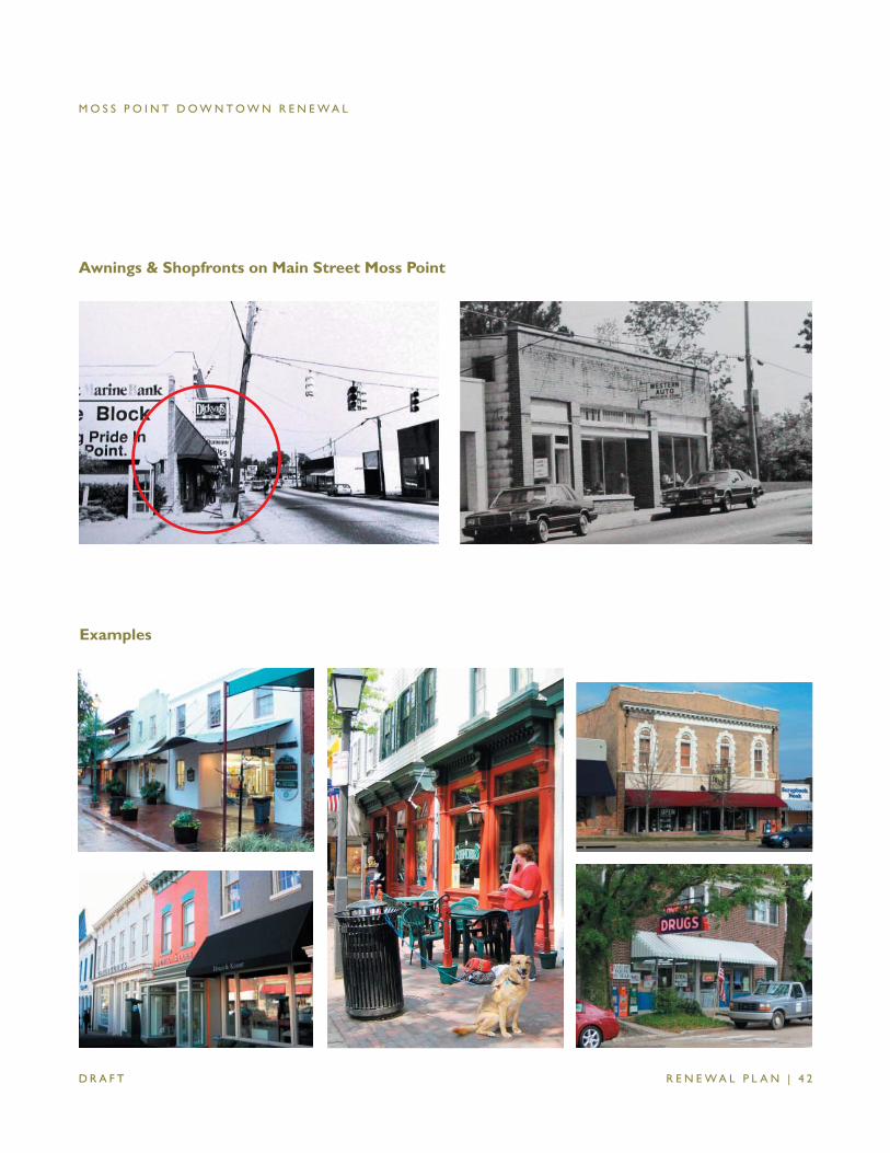
Awnings & Shopfronts on Main Street Moss Point
Examples
M O S S P O I N T D O W N T O W N R E N E W A L
R E N E W A L P L A N | 4 3 D R A F T
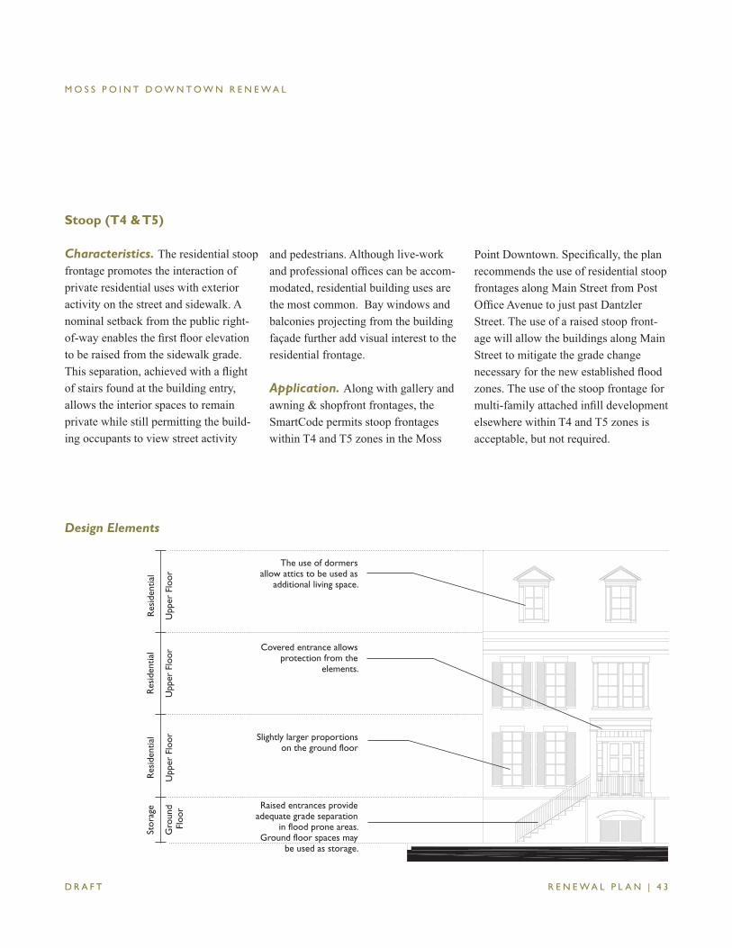
Stoop (T4 & T5)
Characteristics. The residential stoop frontage promotes the interaction of private residential uses with exterior activity on the street and sidewalk. A nominal setback from the public right-of-way enables the fi rst fl oor elevation to be raised from the sidewalk grade. This separation, achieved with a fl ight of stairs found at the building entry, allows the interior spaces to remain private while still permitting the build-ing occupants to view street activity
and pedestrians. Although live-work and professional offi ces can be accom-modated, residential building uses are the most common. Bay windows and balconies projecting from the building façade further add visual interest to the residential frontage.
Application. Along with gallery and awning & shopfront frontages, the SmartCode permits stoop frontages within T4 and T5 zones in the Moss
Point Downtown. Specifi cally, the plan recommends the use of residential stoop frontages along Main Street from Post Offi ce Avenue to just past Dantzler Street. The use of a raised stoop front-age will allow the buildings along Main Street to mitigate the grade change necessary for the new established fl ood zones. The use of the stoop frontage for multi-family attached infi ll development elsewhere within T4 and T5 zones is acceptable, but not required.
The use of dormers allow attics to be used as
additional living space.
Upp
er F
loor
Upp
er F
loor
Res
iden
tial
Res
iden
tial Covered entrance allows
protection from the elements.
Raised entrances provide adequate grade separation
in flood prone areas. Ground floor spaces may
be used as storage.
Upp
er F
loor
Slightly larger proportions on the ground floor
Res
iden
tial
Gro
und
Flo
or
Stor
age
Design Elements
M O S S P O I N T D O W N T O W N R E N E W A L
R E N E W A L P L A N | 4 4 D R A F T
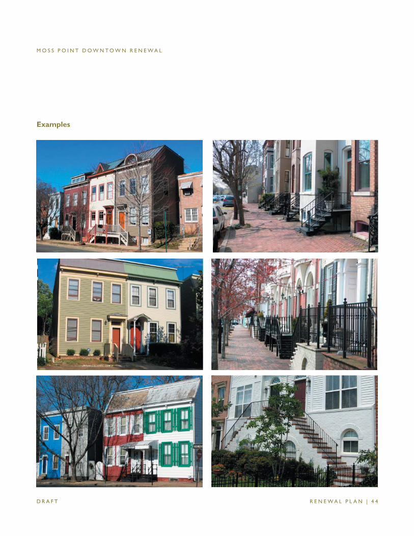
Examples
M O S S P O I N T D O W N T O W N R E N E W A L
R E N E W A L P L A N | 4 5 D R A F T
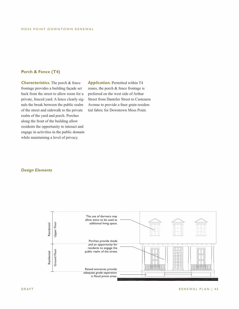
Porch & Fence (T4)
Characteristics. The porch & fence frontage provides a building façade set back from the street to allow room for a private, fenced yard. A fence clearly sig-nals the break between the public realm of the street and sidewalk to the private realm of the yard and porch. Porches along the front of the building allow residents the opportunity to interact and engage in activities in the public domain while maintaining a level of privacy.
Application. Permitted within T4 zones, the porch & fence frontage is preferred on the west side of Arthur Street from Dantzler Street to Castenera Avenue to provide a fi ner grain residen-tial fabric for Downtown Moss Point.
Design Elements
Gro
und
Floo
rU
pper
Flo
or
Res
iden
tial
Res
iden
tial
Raised entrances provide adequate grade separation
in flood prone areas.
Porches provide shade and an opportunity for residents to engage the
public realm of the street.
The use of dormers may allow attics to be used as
additional living space.
M O S S P O I N T D O W N T O W N R E N E W A L
R E N E W A L P L A N | 4 6 D R A F T
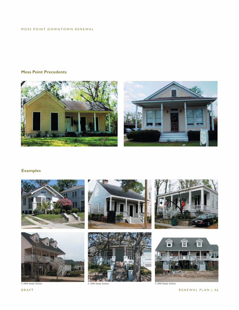
Moss Point Precedents
Examples
© 2006 Sandy Sorlien © 2006 Sandy Sorlien © 2006 Sandy Sorlien
S M A R T C O D E | 1
MOSS POINT DOWNTOWN RENEWAL
SmartCode
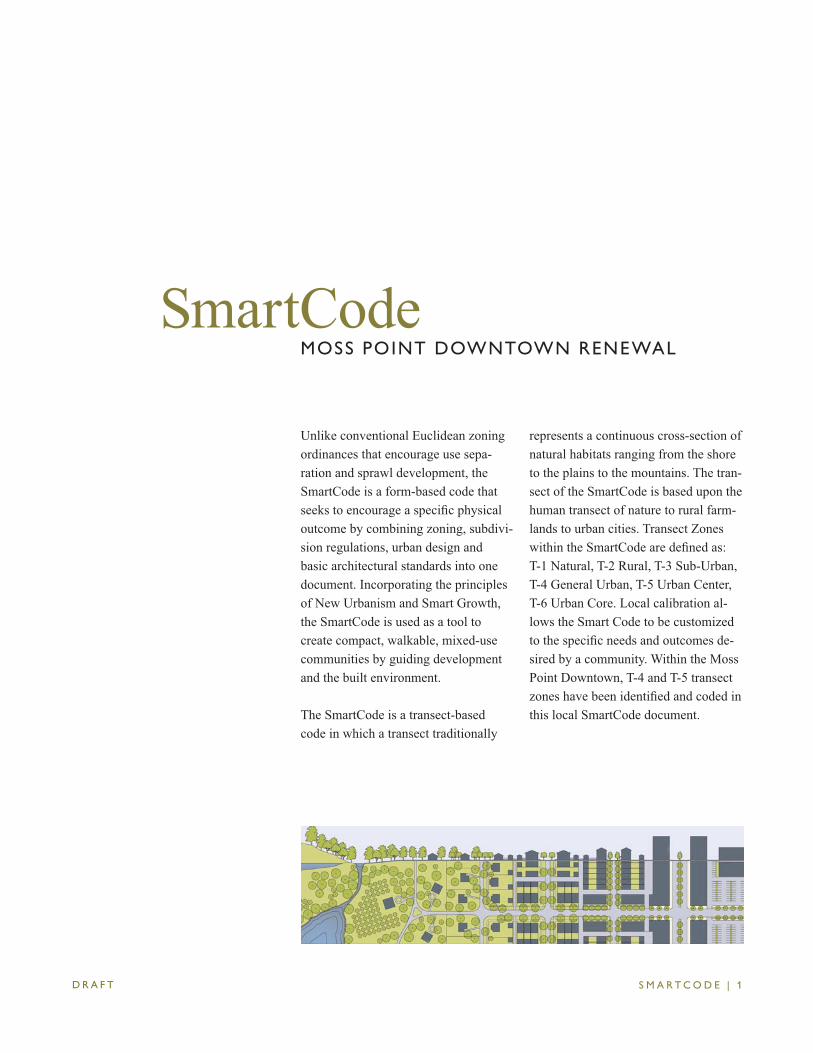
Unlike conventional Euclidean zoning ordinances that encourage use sepa-ration and sprawl development, the SmartCode is a form-based code that seeks to encourage a specifi c physical outcome by combining zoning, subdivi-sion regulations, urban design and basic architectural standards into one document. Incorporating the principles of New Urbanism and Smart Growth, the SmartCode is used as a tool to create compact, walkable, mixed-use communities by guiding development and the built environment.
The SmartCode is a transect-based code in which a transect traditionally
represents a continuous cross-section of natural habitats ranging from the shore to the plains to the mountains. The tran-sect of the SmartCode is based upon the human transect of nature to rural farm-lands to urban cities. Transect Zones within the SmartCode are defi ned as: T-1 Natural, T-2 Rural, T-3 Sub-Urban, T-4 General Urban, T-5 Urban Center, T-6 Urban Core. Local calibration al-lows the Smart Code to be customized to the specifi c needs and outcomes de-sired by a community. Within the Moss Point Downtown, T-4 and T-5 transect zones have been identifi ed and coded in this local SmartCode document.
D R A F T
MOSS POINT DOWNTOWN RENEWAL
S M A R T C O D E | 2D R A F T
MOSS POINT DOWNTOWN RENEWAL
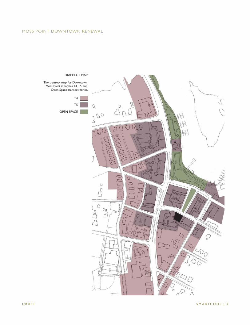
TRANSECT MAP
The transect map for Downtown Moss Point identifies T4, T5, and
Open Space transect zones.
T4
T5
OPEN SPACE
S M A R T C O D E | 3
ARTICLE 1. GENERAL TO ALL PLANS 1.1 AUTHORITY 1.2 PURPOSE 1.3 APPLICABILITY 1.4 PROCESS 1.5 WARRANTS AND VARIANCES 1.6 INCENTIVES
ARTICLE 2. [RESERVED] ARTICLE 3. [RESERVED]
ARTICLE 4. [RESERVED]
ARTICLE 5. BUILDING SCALE PLANS 5.1 INSTRUCTIONS 5.2 [RESERVED] 5.3 [RESERVED] 5.4 SPECIFIC TO T4 ZONES 5.5 SPECIFIC TO T5 ZONES 5.6 [RESERVED] 5.7 PRE-EXISTING CONDITIONS
TABLE OF CONTENTS
ARTICLE 6. STANDARDS & TABLES TABLE 1 TRANSECT ZONE DESCRIPTIONS TABLE 2 [RESERVED] TABLE 3A [RESERVED] TABLE 3B [RESERVED] TABLE 3C [RESERVED] TABLE 4A [RESERVED] TABLE 4B [RESERVED] TABLE 5 [RESERVED] TABLE 6 [RESERVED] TABLE 7 PRIVATE FRONTAGES TABLE 8 BUILDING CONFIGURATION TABLE 9 BUILDING TYPE TABLE 10 BUILDING FUNCTION - SPECIFIC TABLE 11 BUILDING FUNCTION - GENERAL TABLE 12 PARKING CALCULATION TABLE 13 [RESERVED] TABLE 14 [RESERVED] TABLE 15 [RESERVED] TABLE 16 DEFINITIONS ILLUSTRATED
ARTICLE 7. DEFINITIONS OF TERMS
D R A F T
MOSS POINT DOWNTOWN RENEWAL
S M A R T C O D E | 4
1.1 AUTHORITY1.1.1 The action of the City of Moss Point, Mississippi in the adoption of this Code as an
overlay zone is authorized under the Code of Mississippi, Sections 17-1-1 through 17-1-21 (1972), as amended.
1.1.2 The adoption of this ordinance is necessary to promote the health, safety, convenience, and general welfare of the citizens of Moss Point, Mississippi and to assist in bringing about coordinated, effi cient and economical development of the city.
1.1.3 This Code was adopted by and amended by vote of the Moss Point Planning Commis-sion (the “Planning Commisssion”) and the Moss Point Board of Aldermen (the “Board of Aldermen”).
1.2 PURPOSE The purpose of this Code is to enable and encourage the implementation of the following
policies:1.2.1 The Region
a. That the region should retain its natural infrastructure and visual character derived from topography, woodlands, farmlands, riparian corridors and coastlines.
b. That growth strategies should encourage Infi ll and redevelopment in parity with new communities.
c. That development contiguous to urban areas should be structured in the Neighbor-hood pattern and be integrated with the existing urban pattern.
d. That development non-contiguous to urban areas should be organized in the pat-tern of Clustered Land Development, Traditional Neighborhood Developments, and Regional Center Developments.
e. That affordable housing should be distributed throughout the region to match job opportunities and to avoid concen trations of poverty.
f. That transportation corridors should be planned and reserved in coordination with land use.
g. That green corridors should be used to defi ne and connect the urbanized areas. h. That the region should include a framework of transit, pedestrian, and bicycle systems
that provide alternatives to the automobile.1.2.2 The Community
a. That Traditional Neighborhood Developments and Regional Center Developments should be compact, pedestrian-oriented and mixed -use.
b. That Traditional Neighborhood Developments and Regional Center Developments should be the preferred pattern of development and that districts specializing in single-use should be the exception.
c. That ordinary activities of daily living should occur within walking distance of most dwellings, allowing independence to those who do not drive.
d. That interconnected networks of Thoroughfares should be designed to disperse and reduce the length of automobile trips.
ARTICLE 1. GENERAL TO ALL PLANS
D R A F T
MOSS POINT DOWNTOWN RENEWAL
S M A R T C O D E | 5
e. That within developments, a range of housing Types and price levels should be provided to accommodate diverse ages and incomes.
f. That appropriate building densities and land uses should be provided within walking distance of transit stops.
g. That Civic and Commercial activity should be embedded in mixed-use developments, not isolated in remote single-use complexes.
h. That schools should be sized and located to enable children to walk or bicycle to them.
i. That a range of open space including parks, squares, and playgrounds should be distributed within neighborhoods and urban center zones.
1.2.3 The Block and the Building a. That buildings and landscaping should contribute to the physical defi nition of Thor-
oughfares as Civic Spaces. b. That development should adequately accommodate automobiles while respecting
the pedestrian and the spatial form of public space. c. That the design of streets and buildings should reinforce safe environments, but not
at the expense of accessibility. d. That architecture and landscape design should grow from local climate, topography,
history, and building practice. e. That buildings should provide their inhabitants with a clear sense of geography and
climate through energy effi cient methods. f. That Civic Buildings and public gathering places should be provided locations that
reinforce community identity and support self-government. g. That Civic Buildings should be distinctive and appropriate to a role more important
than the other buildings that constitute the fabric of the city. h. That the preservation and renewal of historic buildings should be facilitated to affi rm
the continuity and evolution of society. i. That the harmonious and orderly evolution of urban areas should be secured through
graphic codes that serve as guides for change.
1.3 APPLICABILITY1.3.1 Provisions of this Code are activated by "shall" when mandatory and "should" when
recommended but optional.1.3.2 The provisions of this Code, when in confl ict, shall take precedence over those of other
codes, ordinances, regulations and standards except the local fi re and building codes for Moss Point (the “Local Health and Safety Code”).
1.3.3 [Reserved]1.3.4 Terms used throughout this Code shall be defi ned in the Article 7 Defi nitions of Terms.
Those terms not defi ned in Article 7 shall be accorded their commonly accepted mean-ings. In the event of confl icts between these defi nitions and those of any other laws or ordinances of the City of Moss Point, those of this Code shall take precedence related
ARTICLE 1. GENERAL TO ALL PLANS
D R A F T
MOSS POINT DOWNTOWN RENEWAL
S M A R T C O D E | 6
to the use and application of this Code. 1.3.5 The Article 7 Defi nitions of Terms contains regulatory language that is part of this
Code.
1.4 PROCESS 1.4.1 [Reserved]1.4.2 [Reserved]1.4.3 The City of Moss Point hereby creates a Consolidated Review Committee (CRC) com-
prised of a representative from the Planning Commission, the Board of Adjustment, the City Engineer’s Offi ce, the Fire Department, and the Clerk’s Offi ce for the City of Moss Point. The CRC shall expedite the permitting process by providing a single interface between the Developer and the agencies.
1.4.4 A Developer may appeal a decision of the CRC to the Planning Commission and may appeal a decision of the Planning Commission to the Board of Aldermen.
1.4.5 Should a violation of an approved plan occur during construction, the CRC has the right to require the Developer to stop, remove, and/or mitigate the violation, or to require the Developer to secure a Variance to cover the violation.
1.5 WARRANTS AND VARIANCES1.5.1 There shall be two types of deviations from the requirements of this Code: Warrants and
Variances. Whether a deviation requires a Warrant or Variance shall be determined by the CRC pursuant to regulations promulgated by the CRC.
1.5.2 A Warrant is a minor, technical deviation that would permit a practice that is not consistent with a specifi c provision of this Code, but is justifi ed by its Purpose (Section 1.2). The CRC shall have the authority administratively to approve or disapprove a request for a Warrant pursuant to regulations promulgated by the CRC.
1.5.3 A Variance is any ruling on a deviation other than a Warrant. Variances shall be granted only in accordance with the procedures established by the Board of Adjustment.
1.5.4 The request for a Variance shall not subject the entire application to public hearing, but only that portion necessary to rule on the issue requiring a Variance.
1.5.5 [Reserved]
1.6 INCENTIVES1.6.1 To encourage the use of this Code, the Board of Aldermen grants the following incen-
tives, to the extent authorized by state law: a. Applications under this Code shall be processed administratively by the CRC rather
than through public hearing. b. Applications under this Code shall be processed with priority over others under the
existing conventional zoning code, including those with prior fi ling dates.
ARTICLE 1. GENERAL TO ALL PLANS
D R A F T
MOSS POINT DOWNTOWN RENEWAL

S M A R T C O D E | 7
ARTICLE 2. [RESERVED]
D R A F T
MOSS POINT DOWNTOWN RENEWAL

S M A R T C O D E | 8
ARTICLE 3. [RESERVED]
D R A F T
MOSS POINT DOWNTOWN RENEWAL

S M A R T C O D E | 9D R A F T
MOSS POINT DOWNTOWN RENEWAL
ARTICLE 4. [RESERVED]
S M A R T C O D E | 1 0D R A F T
MOSS POINT DOWNTOWN RENEWAL
5.1 INSTRUCTIONS5.1.1 [Reserved]5.1.2 Developers may have plans under this Article prepared on their behalf. 5.1.3 [Reserved]5.1.4 The requirements described in this Article shall control the Building Disposition, Building
Confi guration and Building Function, as well as their architectural, landscape, parking, signage, and ambient standards.
5.1.5 Plans submitted under this Article shall set forth the following, in compliance with the standards described in this Article:
a. For preliminary site and building approval: • Building Disposition • Building Confi guration • Building Function • Required Parking standards b. For fi nal approval, in addition to the above: • Architectural Standards • Landscape Standards • Signage Standards • Ambient Standards
5.2 [Reserved]
5.3 [Reserved]
ARTICLE 5. BUILDING SCALE PLANS
S M A R T C O D E | 1 1
5.4 SPECIFIC TO GENERAL URBAN TRANSECT ZONES (T4)5.4.1 Building Disposition (T4) a. Newly platted lots shall be dimensioned according to Section 5.4.11 b. Buildings shall be disposed in relation to the boundaries of their lots according to
Section 5.4.11 c. One Principal Building at the Frontage Line, and one Outbuilding to the rear of the
Principal Building, may be built on each lot as shown in Table 16C. d. Lot coverage by building shall not exceed that shown in Section 5.4.11. e. Facades shall be built parallel to a rectilinear Principal Frontage Line or parallel to
the tangent of a curved Principal Frontage Line. f. Setbacks for Principal Buildings shall be as shown in Section 5.4.11. Setbacks shall
match one or the other of the existing adjacent Setbacks. Setbacks may otherwise be adjusted by Warrant.
g. Rear Setbacks for Outbuildings shall be a minimum of 12 feet measured from the centerline of the Rear Alley or Rear Lane easement. In the absence of Rear Alley or Rear Lane, the rear Setback shall be as shown in Section 5.4.11.
h. Building Types shall be as shown in Table 9. i. A minimum Residential housing mix of three Types (none less than 20%) shall be
required in the General Urban Zone (T4), selected from Table 9.5.4.2 Building Confi guration (T4) a. Private Frontage types shall conform to and be allocated in accordance with Table 7
and Section 5.4.11. b. Awnings may encroach the public Sidewalk without limit. Stoops may encroach 100%
of the depth of a Setback. Open porches and awnings may encroach up to 50% of the depth of the Setback. Balconies and bay windows may encroach up to 25% of the depth of the Setback.
c. Loading docks and service areas shall be permitted on Frontage Lines only by Warrant. d. Building Heights shall conform to Table 8 and be as shown in Section 5.4.11.5.4.3 Building Function (T4) a. Buildings in each Transect Zone shall conform to the Building Functions described
in Tables 10 and 11 and Section 5.4.11. Building Functions that do not conform to the requirements of Tables 10 or 11 shall require approval by Warrant.
b. [Reserved] c. [Reserved] d. [Reserved] e. Accessory uses of Limited Lodging or Limited Offi ce shall be permitted within an
Outbulding.
ARTICLE 5. BUILDING SCALE PLANS
D R A F T
MOSS POINT DOWNTOWN RENEWAL
S M A R T C O D E | 1 2
5.4.4 Parking Standards (T4) a. Vehicular parking shall be required and adjusted for mixed-use as shown in Tables
11 and 12. The Required Parking is calculated according to Table 11 based on the building function. The Adjusted Parking is the Required Parking reduced by the sharing factor in Table 12.
b. On-street parking available along the Frontage Lines that correspond to each lot shall be counted toward the Required Parking of the building on the same lot.
c. The Required Parking may be modifi ed by the CRC by Warrant. d. Parking shall be accessed by the Rear Alley or Rear Lane, when such are avail-
able. e. Parking lots shall be masked from the Frontage Line by a Liner Building or Streetscreen
as specifi ed in Section 5.4.5b. f. All parking areas except for Driveways shall be located at the Third Layer as illustrated
in Table 16D. Garages shall be at the Third Layer. g. Subject to approval by Warrant, the Required Parking may be provided within one-
quarter mile of the site that it serves. h. [Reserved] i. [Reserved] j. [Reserved] k. For buildings on Secondary Grids (S-Grids), parking lots may be alllowed in the First Layer
by Warrant. 5.4.5 Architectural Standards (T4) a. Building wall materials may be combined on each Facade only horizontally, with the
heavier below the lighter. b. Streetscreens should be between 3.5 and 8 feet in height and constructed of a
material matching the adjacent building Facade. The Streetscreen may be replaced by a hedge or fence by Warrant. Streetscreens shall have openings no larger than necessary to allow automobile and pedestrian access.
c. All openings, including porches, galleries, arcades and windows, with the exception of storefronts, shall be square or vertical in proportion.
d. Openings above the fi rst Story shall not exceed 50% of the total building wall area, with each Facade being calculated independently.
e. [Reserved] f. Doors and windows that operate as sliders are prohibited along Frontages. g. Pitched roofs, if provided, shall be symmetrically sloped no less than 5:12, except
that porches and attached sheds may be no less than 2:12. h. Flat roofs shall be enclosed by parapets a minimum of 42 inches high, or as required
to conceal mechanical equipment to the satisfaction of the CRC. i. The exterior fi nish material on all Facades shall be limited to brick, wood siding,
cementitious siding and/or stucco.
ARTICLE 5. BUILDING SCALE PLANS
D R A F T
MOSS POINT DOWNTOWN RENEWAL
S M A R T C O D E | 1 3
j. Balconies and porches shall be made of painted wood or metal. k. Fences, if provided within the First Layer shall be painted. Fences at other Layers
may be of wood board or chain link.5.4.6 [Reserved]5.4.7 Landscape Standards (T4) a. A minimum of one tree to match the species of street trees on the Public Frontage
shall be planted within the First Layer for each 30 feet of Frontage Line as illustrated in Table 16D.
b. [Reserved] c. [Reserved] d. Sod shall be permitted by right. e. Outdoor storage shall be screened from view from any Frontage by a Streetscreen
in conformance with Section 5.4.5.b.5.4.8 Signage Standards (T4) a. One address number no more than 6 inches measured vertically shall be attached
to the building in proximity to the Principal Entrance or at a mailbox. b. One blade sign for each business may be permanently installed perpendicular to the
Facade. Such a sign shall not exceed a total of 4 square feet. c. [Reserved] d. There shall be no signage permitted additional to that specifi ed in this section. 5.4.9 Ambient Standards (T4) a. Sound levels measured at the building Frontage Line shall not exceed 65 decibels
from sunrise to sunset and 55 decibels from sunset to sunrise. b. Average lighting levels measured at the building Frontage Line shall not exceed 2.0
fc (foot-candles) .5.4.10 [Reserved]
ARTICLE 5. BUILDING SCALE PLANS
D R A F T
MOSS POINT DOWNTOWN RENEWAL
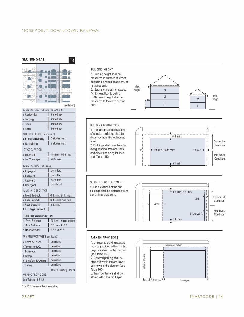
S M A R T C O D E | 1 4
a. Porch & Fenceb.Terrace or L.C.c. Forecourtd. Stoope. Shopfront & Awningf. Gallery
PRIVATE FRONTAGES (see Table 7)
permittedpermittedpermittedpermittedpermittedpermitted
a. Edgeyardb. Sideyardc. Rearyardd. Courtyard
BUILDING TYPE (see Table 9)
permittedprohibited
permittedpermitted
(see Table 1)
a. Residentialb. Lodgingc. Offi ced. Retail
BUILDING FUNCTION (see Tables 10 & 11) limited uselimited uselimited uselimited use
BUILDING HEIGHT (see Table 8) 3 stories max.2 stories max.
a. Principal Buildingb. Outbuilding
a. Front Setbackb. Side Setbackc. Rear Setback
OUTBUILDING DISPOSITION 20 ft. min. + bldg. setback0 ft. min. to 3 ft.3 ft.* to 23 ft.
BUILDING DISPOSITION 6 ft. min. 24 ft. max.0 ft. combined min.3 ft. min.*
a. Front Setbackb. Side Setbackc. Rear Setbackd. Frontage Buildout
a. Lot Widthb. Lot Coverage
LOT OCCUPATION
70% max18 ft min 96 ft max
SECTION 5.4.11 T4
* or 15 ft. from center line of alley
Refer to Summary Table 14PARKING PROVISIONSSee Tables 11 & 12
BUILDING HEIGHT1. Building height shall be measured in number of stories, excluding a raised basement, or inhabited attic. 2. Each story shall not exceed 14 ft. clear, fl oor to ceiling.3. Maximum height shall be measured to the eave or roof deck.
Max. height
Max. height
1
2* 2
1
3 Max.
height
Max.height
3
22*
1 1
BUILDING DISPOSITION1. The facades and elevations of principal buildings shall be distanced from the lot lines as shown. 2. Buildings shall have facades along principal frontage lines and elevations along lot lines. (see Table 16E).
Corner LotCondition
Mid-Block Condition
6 ft. min. 24 ft. max.
6 ft. min.
0 ft. min.
3 ft. min.
1. The elevations of the out buildings shall be distances from the lot lines as shown.
20 ft.3 ft. Corner Lot
Condition
Mid-Block Condition3 ft. or 23 ft.
0 ft. min.
0 ft. min. 3 ft. max.
OUTBUILDING PLACEMENT
2nd Layer
PARKING PROVISIONS1. Uncovered parking spaces may be provided within the 3rd Layer as shown in the diagram (see Table 16D). 2. Covered parking shall be provided within the 3rd Layer as shown in the diagram (see Table 16D). 3. Trash containers shall be stored within the 3rd Layer.
2nd Layer 3rd Layer1st Layer
Principal Frontage
Secondary Frontage
D R A F T
MOSS POINT DOWNTOWN RENEWAL
S M A R T C O D E | 1 5
5.5 SPECIFIC TO URBAN CENTER TRANSECT ZONES (T5)5.5.1 Building Disposition (T5) a. Newly platted lots shall be dimensioned according to Section 5.5.11 b. Buildings shall be disposed in relation to the boundaries of their lots according to
Section 5.5.11 c. One Principal Building at the Frontage Line, and one Outbuilding to the rear of the
Prinicipal Building, may be built on each lot as shown in Table 16C. d. Lot coverage by building shall not exceed that shown in Section 5.5.11. e. Facades shall be built parallel to the Principal Frontage Line along a minimum of 70%
of its length on the Setback shown in Section 5.5.11. In the absence of a building along the remainder of the Frontage Line, a Streetscreen shall be built co-planar with the Facade.
f. Setbacks for Principal Buildings shall be as shown in Section 5.5.11. Setbacks shall match one or the other of the existing adjacent Setbacks. Setbacks may otherwise be adjusted by Warrant.
g. Rear Setbacks for Outbuildings shall be a minimum of 12 feet measured from the centerline of the Rear Alley or Rear Lane easement. In the absence of Rear Alley or Rear Lane, the rear Setback shall be as shown in Section 5.5.11.
h. Building Types shall be as shown in Table 9. i. [Reserved] j. Buildings shall have their Principal Entrances on a Frontage Line.5.5.2 Building Confi guration (T5) a. Private Frontage types shall conform to and be allocated in accordance with Table 7
and Section 5.5.11. b. Awnings may encroach the public Sidewalk without limit. Stoops may encroach 100%
of the depth of a Setback. Open porches and awnings may encroach up to 50% of the depth of the Setback. Balconies and bay windows may encroach up to 25% of the depth of the Setback.
c. Loading docks and service areas shall be permitted on the Frontage Line only by Warrant. d. Building Heights shall conform to Table 8 and be as shown in Section 5.5.11. e. A fi rst level Residential or Lodging Function shall be raised a minimum of 2 feet from
average Sidewalk grade.5.5.3 Building Function (T5) a. Buildings in each Transect Zone shall conform to the Building Functions described
in Tables 10 and 11 and Section 5.5.11. Building Functions that do not conform to the requirements of Tables 10 or 11 shall require approval by Warrant.
b. [Reserved] c. [Reserved] d. [Reserved]
ARTICLE 5. BUILDING SCALE PLANS
D R A F T
MOSS POINT DOWNTOWN RENEWAL
S M A R T C O D E | 1 6
e. Accessory uses of Open Lodging or Open Offi ce shall be permitted within an Out-building.
f. First Story Commercial shall be permitted throughout and shall be required at manda-tory shopfront Frontages.
5.5.4 Parking Standards (T5) a. Vehicular parking shall be required and adjusted for mixed-use as shown in Tables
11 and 12. The Required Parking is calculated according to Table 11 based on the Building Function. The Adjusted Parking is the Required Parking reduced by the Sharing Factor in Table 12.
b. On-street parking available along the Frontage Lines that correspond to each lot shall be counted toward the parking requirement of the building on the same lot.
c. Maximum Parking ratios may be established by the CRC by Warrant. d. Parking shall be accessed by the Rear Alley or Rear Lane when such is available. e. Parking lots shall be masked from the Frontage Line by a Liner Building or Streetscreen
as specifi ed in Section 5.5.5b. f. All parking areas shall be located at the Third Lot Layer . g. The Required Parking may be provided within one-quarter mile of the site that it
serves, subject to approval by Variance. h. The vehicular entrance of a parking lot or garage on a Frontage Line shall be no
wider than 30 feet. i. Pedestrian entrances to all parking lots and parking structures shall be directly from
a Frontage Line. j. [Reserved] k. For buildings on Secondary Grids (S-Grids), parking lots may be alllowed on the Frontage
Line by Warrant. 5.5.5 Architectural Standards (T5) a. Building wall materials may be combined on each Facade only horizontally, with the
heavier below the lighter. b. Streetscreens should be between 3.5 and 8 feet in height and constructed of a
material matching the adjacent building Facade. The Streetscreen may be replaced by a hedge or fence by Warrant. Streetscreens shall have openings no larger than necessary to allow automobile and pedestrian access.
c. All openings, including porches, galleries, arcades and windows, with the exception of storefronts, shall be square or vertical in proportion.
d. Openings above the fi rst Story shall not exceed 50% of the total building wall area, with each Facade being calculated independently.
e. The Facades on Retail Frontages shall be detailed as storefronts and glazed with clear glass no less than 70% of the sidewalk-level story.
f. Doors and windows that operate as sliders are prohibited along Public and Private Frontages.
g. Buildings may have fl at roofs enclosed by parapets or sloped roofs. Pitched roofs
ARTICLE 5. BUILDING SCALE PLANS
D R A F T
MOSS POINT DOWNTOWN RENEWAL
S M A R T C O D E | 1 7
shall be symmetrically sloped no less than 5:12, except that porches and attached sheds may be no less than 2:12.
h. Flat roofs shall be enclosed by parapets a minimum of 42 inches high, or as required to conceal mechanical equipment to the satisfaction of the CRC.
i. The exterior fi nish materials on all Facades shall be limited to stone, brick and/or stucco.
j. Balconies, galleries and arcades shall be made of concrete, painted wood or metal. k. Streetscreens shall be located coplanar with the Frontage Line as shown in Table
16D. 5.5.6 [Reserved]5.5.7 Landscape Standards (T5) a. [Reserved] b. [Reserved] c. [Reserved] d. Trees shall be a species with shade canopies that, at maturity, begin higher than the
top of the second Story of buildings. e. Outdoor storage shall be screened from view from any Frontage Line by a Streetscreen
in conformance with Section 5.5.5b.5.5.8 Signage Standards (T5) a. One address number no more than 6 inches measured vertically shall be attached
to the building in proximity to the Principal Entrance or at a mailbox. b. Blade signs, not to exceed 6 square ft. for each separate business entrance, may be
attached perpendicular to the Facade. c. [Reserved] d. A single external sign band may be applied to the Facade of each building, providing
that such sign not exceed 3 feet in height by any length. e. Signage shall be externally lit, except that signage within the shopfront glazing may
be neon lit. 5.5.9 Ambient Standards (T5) a. Sound levels measured at the building Frontage Line shall not exceed 70 decibels from
sunrise to midnight and 60 decibels from midnight to sunrise. b. Average lighting levels measured at the building Frontage Line shall not exceed 5.0
fc (foot-candles). 5.5.10 [Reserved]
ARTICLE 5. BUILDING SCALE PLANS
D R A F T
MOSS POINT DOWNTOWN RENEWAL
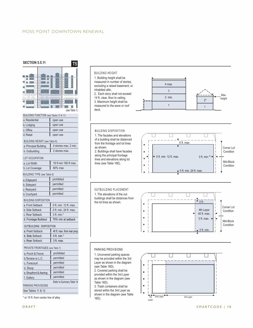
S M A R T C O D E | 1 8
(see Table 1)
a. Edgeyardb. Sideyardc. Rearyardd. Courtyard
BUILDING TYPE (see Table 9)
permittedpermitted
prohibitedpermitted
a. Residentialb. Lodgingc. Offi ced. Retail
BUILDING FUNCTION (see Tables 10 & 11) open useopen useopen useopen use
a. Porch & Fenceb.Terrace or L.C.c. Forecourtd. Stoope. Shopfront & Awningf. Gallery
PRIVATE FRONTAGES (see Table 7)
prohibitedpermittedpermittedpermittedpermittedpermitted
a. Front Setbackb. Side Setbackc. Rear Setback
OUTBUILDING DISPOSITION40 ft. max. from rear prop.0 ft. min.*3 ft. max.
BUILDING DISPOSITION 0 ft. min. 12 ft. max.0 ft. min. 24 ft. max.3 ft. min.*70% min at setback
a. Front Setbackb. Side Setbackc. Rear Setbackd. Frontage Buildout
BUILDING HEIGHT (see Table 8) a. Principal Buildingb. Outbuilding
4 stories max. 2 min.2 stories max.
a. Lot Widthb. Lot Coverage
LOT OCCUPATION
80% max18 ft min 180 ft max
SECTION 5.5.11 T5
* or 15 ft. from center line of alley
Refer to Summary Table 14PARKING PROVISIONSSee Tables 11 & 12
Max. height
1
2*
BUILDING HEIGHT1. Building height shall be measured in number of stories, excluding a raised basement, or inhabited attic. 2. Each story shall not exceed 14 ft. clear, fl oor to ceiling.3. Maximum height shall be measured to the eave or roof deck.
2 min.
1
3
4 max.
Max. height
112*
2 min.
3
4 max.
BUILDING DISPOSITION1. The facades and elevations of a building shall be distanced from the frontage and lot lines as shown. 2. Buildings shall have facades along the principal frontage lines and elevations along lot lines (see Table 16E).
0 ft. min. 12 ft. max.
6 ft. max.
0 ft. min. 24 ft. max.
3 ft. min.**
Corner LotCondition
Mid-Block Condition
0 ft. min. 12 ft. max.
0 ft. min. 24 ft. max.
3 ft. min.**
1. Uncovered parking spaces may be provided within the 3rd Layer as shown in the diagram (see Table 16D). 2. Covered parking shall be provided within the 3rd Layer as shown in the diagram (see Table 16D). 3. Trash containers shall be stored within the 3rd Layer as shown in the diagram (see Table 16D).
PARKING PROVISIONS
2nd Layer 3rd Layer1st Layer
0 ft. min.
0 ft.
4th Layer40 ft. max.
Corner LotCondition
Mid-Block Condition
3 ft. max.
1. The elevations of the out buildings shall be distances from the lot lines as shown.
OUTBUILDING PLACEMENT
D R A F T
MOSS POINT DOWNTOWN RENEWAL
S M A R T C O D E | 1 9
5.6 [Reserved]
5.7 PRE-EXISTING CONDITIONS5.7.1 Non-conforming existing buildings may continue to be used as is until a Substantial
Modifi cation is requested. Once a substantial modifi cation is requested, the CRC shall require the Developer remedy the non-conformity.
5.7.2 When renovating an existing building, a Developers shall not be required to increase the Required Parking for the the building more than the amount of parking that was required for the building prior to the renovation.
ARTICLE 5. BUILDING SCALE PLANS
D R A F T
MOSS POINT DOWNTOWN RENEWAL
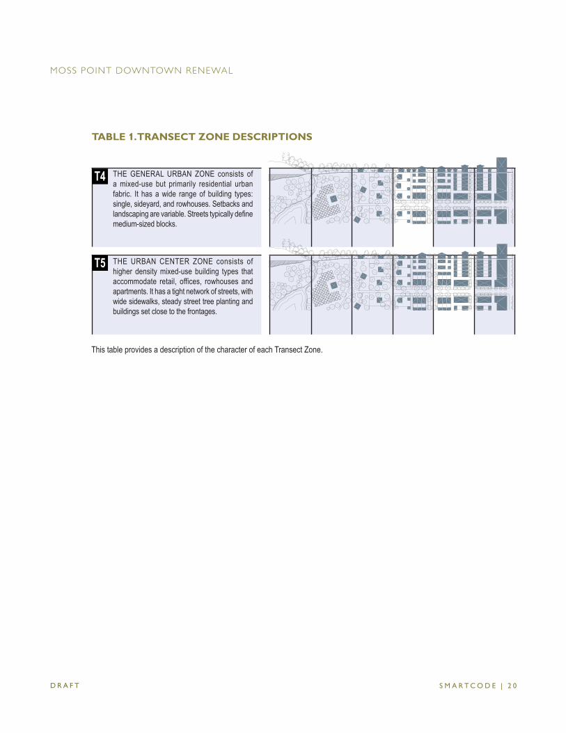
S M A R T C O D E | 2 0
THE GENERAL URBAN ZONE consists of a mixed-use but primarily residential urban fabric. It has a wide range of building types: single, sideyard, and rowhouses. Setbacks and landscaping are variable. Streets typically defi ne medium-sized blocks.
THE URBAN CENTER ZONE consists of higher density mixed-use building types that accommodate retail, offices, rowhouses and apartments. It has a tight network of streets, with wide sidewalks, steady street tree planting and buildings set close to the frontages.
T4
T5
TABLE 1. TRANSECT ZONE DESCRIPTIONS
D R A F T
MOSS POINT DOWNTOWN RENEWAL
This table provides a description of the character of each Transect Zone.

S M A R T C O D E | 2 1
TABLE 2-6. [RESERVED]
D R A F T
MOSS POINT DOWNTOWN RENEWAL
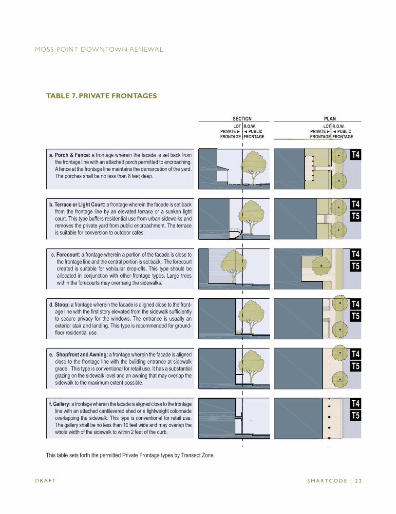
S M A R T C O D E | 2 2D R A F T
MOSS POINT DOWNTOWN RENEWAL
TABLE 7. PRIVATE FRONTAGES
SECTION PLANLOT
PRIVATE ►FRONTAGE
R.O.W.◄ PUBLIC FRONTAGE
LOT PRIVATE ►FRONTAGE
R.O.W.◄ PUBLIC FRONTAGE
a. Porch & Fence: a frontage wherein the facade is set back from the frontage line with an attached porch permitted to encroaching. A fence at the frontage line maintains the demarcation of the yard. The porches shall be no less than 8 feet deep.
b. Terrace or Light Court: a frontage wherein the facade is set back from the frontage line by an elevated terrace or a sunken light court. This type buffers residential use from urban sidewalks and removes the private yard from public encroachment. The terrace is suitable for conversion to outdoor cafes.
T4T5
c. Forecourt: a frontage wherein a portion of the facade is close to the frontage line and the central portion is set back. The forecourt created is suitable for vehicular drop-offs. This type should be allocated in conjunction with other frontage types. Large trees within the forecourts may overhang the sidewalks.
T4T5
d. Stoop: a frontage wherein the facade is aligned close to the front-age line with the fi rst story elevated from the sidewalk suffi ciently to secure privacy for the windows. The entrance is usually an exterior stair and landing. This type is recommended for ground-fl oor residential use.
T4T5
e. Shopfront and Awning: a frontage wherein the facade is aligned close to the frontage line with the building entrance at sidewalk grade. This type is conventional for retail use. It has a substantial glazing on the sidewalk level and an awning that may overlap the sidewalk to the maximum extent possible.
T4T5
f. Gallery: a frontage wherein the facade is aligned close to the frontage line with an attached cantilevered shed or a lightweight colonnade overlapping the sidewalk. This type is conventional for retail use. The gallery shall be no less than 10 feet wide and may overlap the whole width of the sidewalk to within 2 feet of the curb.
T4T5
T4
This table sets forth the permitted Private Frontage types by Transect Zone.
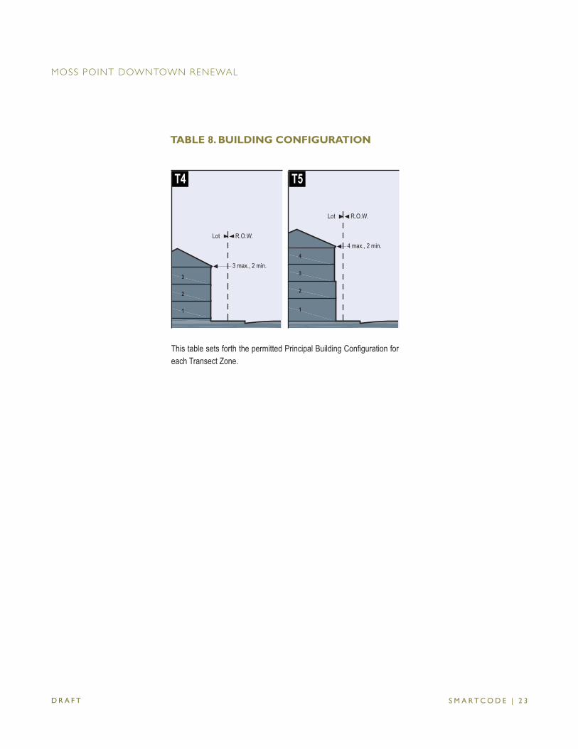
S M A R T C O D E | 2 3
T4 T5
3
2
1
4
3
2
1
3 max., 2 min.
R.O.W.Lot4 max., 2 min.
R.O.W.Lot
D R A F T
MOSS POINT DOWNTOWN RENEWAL
This table sets forth the permitted Principal Building Confi guration for each Transect Zone.
TABLE 8. BUILDING CONFIGURATION
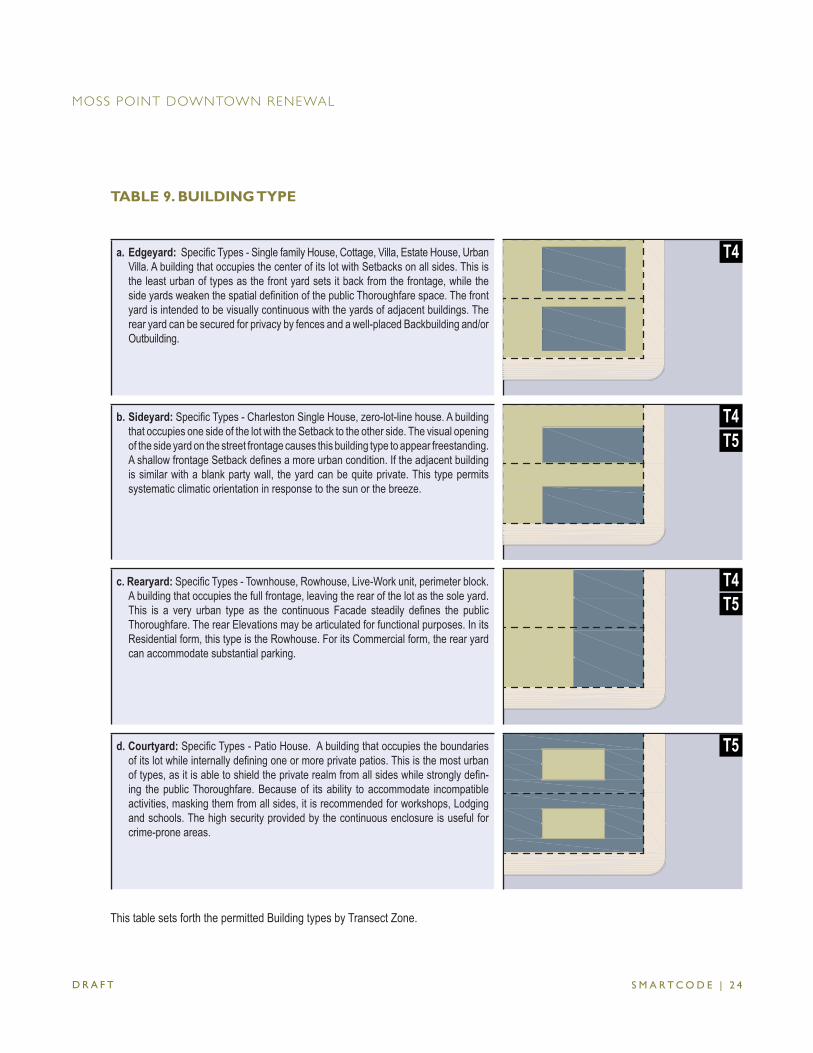
S M A R T C O D E | 2 4
a. Edgeyard: Specifi c Types - Single family House, Cottage, Villa, Estate House, Urban Villa. A building that occupies the center of its lot with Setbacks on all sides. This is the least urban of types as the front yard sets it back from the frontage, while the side yards weaken the spatial defi nition of the public Thoroughfare space. The front yard is intended to be visually continuous with the yards of adjacent buildings. The rear yard can be secured for privacy by fences and a well-placed Backbuilding and/or Outbuilding.
b. Sideyard: Specifi c Types - Charleston Single House, zero-lot-line house. A building that occupies one side of the lot with the Setback to the other side. The visual opening of the side yard on the street frontage causes this building type to appear freestanding. A shallow frontage Setback defi nes a more urban condition. If the adjacent building is similar with a blank party wall, the yard can be quite private. This type permits systematic climatic orientation in response to the sun or the breeze.
T4T5
c. Rearyard: Specifi c Types - Townhouse, Rowhouse, Live-Work unit, perimeter block. A building that occupies the full frontage, leaving the rear of the lot as the sole yard. This is a very urban type as the continuous Facade steadily defi nes the public Thoroughfare. The rear Elevations may be articulated for functional purposes. In its Residential form, this type is the Rowhouse. For its Commercial form, the rear yard can accommodate substantial parking.
d. Courtyard: Specifi c Types - Patio House. A building that occupies the boundaries of its lot while internally defi ning one or more private patios. This is the most urban of types, as it is able to shield the private realm from all sides while strongly defi n-ing the public Thoroughfare. Because of its ability to accommodate incompatible activities, masking them from all sides, it is recommended for workshops, Lodging and schools. The high security provided by the continuous enclosure is useful for crime-prone areas.
T5
T4T5
T4
D R A F T
MOSS POINT DOWNTOWN RENEWAL
This table sets forth the permitted Building types by Transect Zone.
TABLE 9. BUILDING TYPE
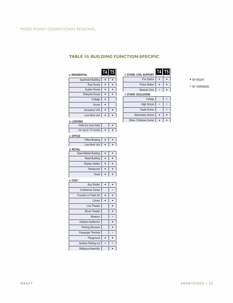
S M A R T C O D E | 2 5
TABLE 10. BUILDING FUNCTION-SPECIFIC
D R A F T
MOSS POINT DOWNTOWN RENEWAL
a. RESIDENTIAL T4 T5Apartment Building ▪ ▪
Row House ▪ ▪Duplex House ▪ ▪
Sideyard House ▪ ▪Cottage ▪
House ▪Accessory Unit ▪ ▪Live-Work Unit ▪ ▪
b. LODGINGHotel (no room limit) ▪Inn (up to 12 rooms) ▪ ▪
c. OFFICEOffi ce Building ▪ ▪Live-Work Unit ▪ ▪
d. RETAILOpen-Market Building ▪ ▪
Retail Building ▪ ▪Display Gallery ▪ ▪
Restaurant ▪ ▪Kiosk ▪ ▪
e. CIVICBus Shelter ▪ ▪
Conference Center ▫Fountain or Public Art ▪ ▪
Library ▪ ▪Live Theater ▪
Movie Theater ▪Museum ▫
Outdoor Auditorium ▪Parking Structure ▪
Passenger Terminal ▫Playground ▪ ▪
Surface Parking Lot ▫ ▫Religious Assembly ▪
f. OTHER: CIVIL SUPPORT
Fire Station ▪ ▪Police Station ▪ ▪Medical Clinic ▫ ▪
f. OTHER: EDUCATIONCollege ▫
High School ▫ ▫Trade School ▫
Elementary School ▪ ▪Other- Childcare Center ▪ ▪
▪ BY RIGHT
▫ BY VARIANCE
T4 T5
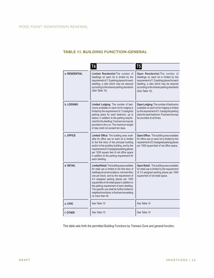
S M A R T C O D E | 2 6
TABLE 11. BUILDING FUNCTION-GENERAL
D R A F T
MOSS POINT DOWNTOWN RENEWAL
This table sets forth the permitted Building Functions by Transect Zone and general function.
T4 T5
a. RESIDENTIAL Limited Residential:The number of dwellings on each lot is limited by the requirement of 1.5 parking places for each dwelling, a ratio which may be reduced according to the shared parking standards (See Table 10).
Open Residential:The number of dwellings on each lot is limited by the requirement of 1.5 parking places for each dwelling, a ratio which may be reduced according to the shared parking standards (See Table 10).
b. LODGING Limited Lodging: The number of bed-rooms available on each lot for lodging is limited by the requirement of 1.0 assigned parking place for each bedroom, up to twelve, in addition to the parking require-ment for the dwelling. Food service may be provided in the a.m. The maximum length of stay shall not exceed ten days.
Open Lodging: The number of bedrooms available on each lot for lodging is limited by the requirement of 1.0 assigned parking place for each bedroom. Food service may be provided at all times.
c. OFFICE Limited Offi ce: The building area avail-able for offi ce use on each lot is limited to the fi rst story of the principal building and/or to the ancillary building, and by the requirement of 3.0 assigned parking places per 1000 square feet of net offi ce space in addition to the parking requirement for each dwelling.
Open Offi ce: The building area available for offi ce use on each lot is limited by the requirement of 2.0 assigned parking places per 1000 square feet of net offi ce space.
d. RETAIL Limited Retail: The building area available for retail use is limited to the fi rst story of buildings at corner locations, not more than one per block, and by the requirement of 4.0 assigned parking places per 1000 square feet of net retail space in addition to the parking requirement of each dwelling. The specifi c use shall be further limited to neighborhood store, or food service seating no more than 40.
Open Retail: The building area available for retail use is limited by the requirement of 3.0 assigned parking places per 1000 square feet of net retail space.
e. CIVIC See Table 10 See Table 10
f. OTHER See Table 10 See Table 10
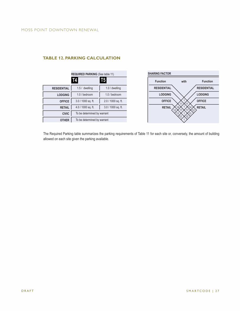
S M A R T C O D E | 2 7
TABLE 12. PARKING CALCULATION
SHARING FACTOR
Function with Function
RESIDENTIAL RESIDENTIAL
LODGING LODGING
OFFICE OFFICE
RETAIL RETAIL1.4 1.1
1.2 1.7 1.3
1.2
1.11.4
1.2
1
1
1
1
1.7 1.3
1.2
REQUIRED PARKING (See table 11)
RESIDENTIAL 1.5 / dwelling 1.0 / dwelling
LODGING 1.0 / bedroom 1.0 / bedroom
OFFICE 3.0 / 1000 sq. ft. 2.0 / 1000 sq. ft.
RETAIL 4.0 / 1000 sq. ft. 3.0 / 1000 sq. ft.
CIVIC To be determined by warrant
OTHER To be determined by warrant
T4 T5
The Required Parking table summarizes the parking requirements of Table 11 for each site or, conversely, the amount of building allowed on each site given the parking available.
D R A F T
MOSS POINT DOWNTOWN RENEWAL
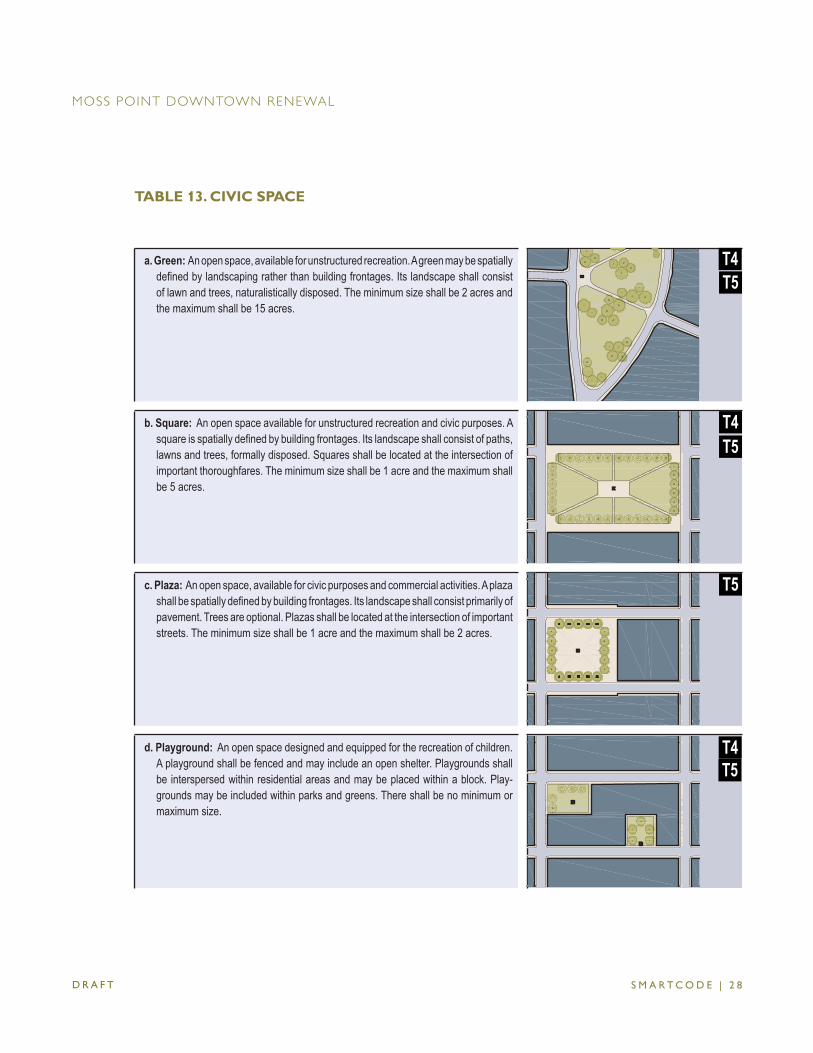
S M A R T C O D E | 2 8
a. Green: An open space, available for unstructured recreation. A green may be spatially defi ned by landscaping rather than building frontages. Its landscape shall consist of lawn and trees, naturalistically disposed. The minimum size shall be 2 acres and the maximum shall be 15 acres.
T5
b. Square: An open space available for unstructured recreation and civic purposes. A square is spatially defi ned by building frontages. Its landscape shall consist of paths, lawns and trees, formally disposed. Squares shall be located at the intersection of important thoroughfares. The minimum size shall be 1 acre and the maximum shall be 5 acres.
T4T5
c. Plaza: An open space, available for civic purposes and commercial activities. A plaza shall be spatially defi ned by building frontages. Its landscape shall consist primarily of pavement. Trees are optional. Plazas shall be located at the intersection of important streets. The minimum size shall be 1 acre and the maximum shall be 2 acres.
T5
d. Playground: An open space designed and equipped for the recreation of children. A playground shall be fenced and may include an open shelter. Playgrounds shall be interspersed within residential areas and may be placed within a block. Play-grounds may be included within parks and greens. There shall be no minimum or maximum size.
T4T5
T4
TABLE 13. CIVIC SPACE
D R A F T
MOSS POINT DOWNTOWN RENEWAL
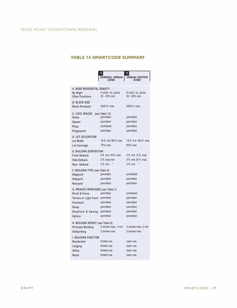
S M A R T C O D E | 2 9
T4 GENERAL URBAN
ZONE
T5 URBAN CENTER
ZONE
A. BASE RESIDENTIAL DENSITYBy Right 4 units / ac. gross 6 units / ac. grossOther Funct ions 20 - 30% min 30 - 50% min
B. BLOCK SIZEBlock Per imeter 2400 ft. max 2000 ft. max
C. CIVIC SPACES (see Table 13)Green permitted permittedSquare permitted permittedPlaza prohibited permittedPlayground permitted permitted
D. LOT OCCUPATIONLot Width 18 ft. min 96 ft. max 18 ft. min 180 ft. maxLot Coverage 70% max 80% max
E. BUILDING DISPOSITIONFront Setback 6 ft. min 18 ft. max 0 ft. min 12 ft. maxSide Setback 0 ft. total min 0 ft. min 24 ft. maxRear Setback 3 ft. min * 3 ft. min *
F. BUILDING TYPE (see Table 9 )Edgeyard permitted prohibitedSideyard permitted permittedRearyard permitted permitted
G. PRIVATE FRONTAGES (see Table 7 )Porch & Fence permitted prohibitedTerrace or L ight Court permitted permittedForecourt permitted permittedStoop permitted permittedS h o p f r o n t & Aw n i n g permitted permittedGal lery permitted permitted
H. BUILDING HEIGHT (see Table 8 )Pr inc ipa l Bui ld ing 3 stories max, 1 min 4 stories max, 2 minOutbui ld ing 2 stories max 2 stories max
I . BUILDING FUNCTIONResident ia l limited use open useLodging limited use open useOff ice limited use open useReta i l limited use open use
TABLE 14. SMARTCODE SUMMARY
D R A F T
MOSS POINT DOWNTOWN RENEWAL

S M A R T C O D E | 3 0
TABLE 15. [RESERVED]
D R A F T
MOSS POINT DOWNTOWN RENEWAL
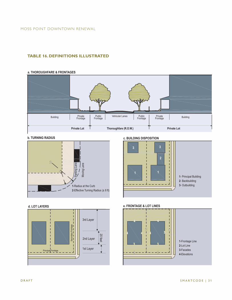
S M A R T C O D E | 3 1
Thoroughfare (R.O.W.)
a. THOROUGHFARE & FRONTAGES
1-Radius at the Curb2-Effective Turning Radius (± 8 ft)
b. TURNING RADIUS
1-Frontage Line 2-Lot Line 3-Facades 4-Elevations
e. FRONTAGE & LOT LINES
1st Layer
2nd Layer
3rd Layer
20 feet
Principal Frontage
Seco
ndar
y Fro
ntage
d. LOT LAYERS
1- Principal Building2- Backbuilding3- Outbuilding
c. BUILDING DISPOSITION
BuildingPrivateFrontage
PublicFrontage
Vehicular LanesPublicFrontage
PrivateFrontageBuilding
Private LotPrivate Lot
Parki
ng La
ne
Movin
g Lan
e
1
22
11 1
2
33
2244
33
33
44 44
11
11
33
11
44 44
TABLE 16. DEFINITIONS ILLUSTRATED
D R A F T
MOSS POINT DOWNTOWN RENEWAL
S M A R T C O D E | 3 2
This Article provides defi nitions for terms in this Code that are technical in nature or that other-wise may not refl ect a common usage of the term. If a term is not defi ned in this Article, then the CRC shall determine the correct defi nition of the term.
DEFINITIONS
Adjusted Parking: the amount of Required Parking adjusted by the Sharing Factor in Table 12.
Apartment: a Residential unit sharing a building and a lot with other units and/or uses. Apartments may be for rent or for sale as condominiums.
Backbuilding: a single-story structure connecting a Principal Building to an Outbuilding (see Table 16).
Block: the aggregate of private lots, Passages, Rear Lanes and Rear Alleys, circum-scribed by Thoroughfares.
Block Face: the aggregate of all the building facades on one side of a Block. The Block Face provides the context for establishing architectural harmony.
Building Confi guration: the form of a building, based on its massing, private frontage, and height.
Building Disposition: the placement of a building on its lot (see Tables 9 & 16). Building Function: the uses accommodated by a building and its lot. Functions are
categorized as Restricted, Limited, or Open, according to the intensity of the use (see Tables 10 & 11).
Building Height: the vertical extent of a building measured in stories, not including a raised basement or a habitable attic. Height limits do not apply to masts, belfries, clock towers, chimney fl ues, water tanks, elevator bulkheads and similar structures. Building Height shall be measured from the average grade of the enfronting thoroughfare (see Table 8).
Building Type: a structure category determined by function, disposition on the lot, and confi guration, including frontage and height.
By Right: a proposal for a Building Plan that complies with this Code and may thereby be processed administratively, without public hearing.
Civic: the term defi ning not-for-profi t organizations dedicated to arts, culture, education, recreation, government, transit, and municipal parking.
Civic Function: Civic Function are composed of Civic Spaces and Civic Buildings. Civic Space: an outdoor area dedicated for public use. Civic Space types are defi ned
by the combination of certain physical constants including the relationship between their intended use, their size, their landscaping and their Enfronting buildings
Commercial: the term collectively defi ning workplace, offi ce and retail functions. Context: surroundings made up of the particular combination of elements that create
ARTICLE 7. DEFINITION OF TERMS
D R A F T
MOSS POINT DOWNTOWN RENEWAL
S M A R T C O D E | 3 3
specifi c habitat. Corridor: a lineal geographic system incorporating transportation and/or greenway
trajectories. A transportation corridor may be a lineal urban Transect Zone. Courtyard Building: a building that occupies the boundaries of its lot while internally
defi ning one or more private patios. Density: the number of units within a standard measure of land area. Developer: the individual or entity submitting an application under the SmartCode. Edgeyard Building: a building that occupies the center of its lot with setbacks on all
sides. Elevation: an exterior wall of a building not along a Frontage Line. Enfront: to place an element along a frontage line, as in “porches enfront the street.” Facade: the exterior wall of a building that is set along a Frontage Line. Frontage Line: those Lot Lines that coincide with a Public Frontage. Facades along
Frontage Lines defi ne the public realm and are therefore more regulated than the eleva-tions that coincide with other Lot Lines (see Table 16).
Home Occupation: non-retail Commercial enterprises permitted in Transect Zones T3-6. The work quarters should be invisible from the frontage, located either within the house or in an Outbuilding. Permitted activities are defi ned by the Restricted Offi ce category.
Independent Building: a building designed by a different architect from the adjacent buildings.
Inside Turning Radius: the curved edge of a Thoroughfare at an intersection, measured at the inside edge of the vehicular tracking. The smaller the Turning Radius, the smaller the pedestrian crossing distance and the more slowly the vehicle is forced to make the turn. (See Tables 3 and 16)
Layer: a range of depth of a lot within which certain elements are permitted (see Table 16).
Liner Building: a building specifi cally designed to mask a parking lot or a parking garage from a frontage. A Liner Building, if less than 30 feet deep and two stories, shall be exempt from parking requirements.
Live-Work: a unit that contains a Commercial component anywhere in the unit. Lodging: premises available for daily and weekly renting of bedrooms. The area allocated
for food service shall be calculated and provided with parking according to Retail use. Lot Line: the boundary that legally and geometrically demarcates a lot. Lot Width: the length of the principal Frontage Line of a lot. Manufacturing: premises available for the creation, assemblage and/or repair of artifacts,
using table-mounted electrical machinery and including their retail sale. Mixed Use: multiple functions within the same building through superimposition or adja-
cency, or in multiple buildings within the same area by adjacency. Offi ce: premises available for the transaction of general business but excluding Retail
and Manufacturing uses.
ARTICLE 7. DEFINITION OF TERMS
D R A F T
MOSS POINT DOWNTOWN RENEWAL
S M A R T C O D E | 3 4
Outbuilding: an accessory building, usually located towards the rear of the same lot as a Principal Building. It is sometimes connected to the principal building by a Backbuilding. Outbuildings shall not exceed 600 square feet of habitable space, excluding parking areas (see Table 16).
Parking Structure: a building containing two or more stories of parking. Parking Struc-tures shall have Liner Buildings at the fi rst Story or higher.
Planter: the element of the public streetscape which accommodates street trees. Plant-ers may be continuous or individual.
Principal Frontage: (See Table 16) Principal Building: the main building on a lot, usually located toward the frontage (see
Table 16). Principal Entrance: the main point of access of pedestrians into a building. Private Frontage: the privately held layer between the Frontage Line and the principal
building facade. The structures and landscaping within the Private Frontage may be held to specifi c standards. The variables of Private Frontage are the depth of the setback and the combination of architectural elements such as fences, stoops, porches and galleries.
Public Frontage: the area between the curb of the vehicular lanes and the Frontage Line. Elements of the Public Frontage include the Type of Planter, Curb, Sidewalk, street tree and streetlight.
Rearyard Building: a building that occupies the full Frontage Line, leaving the rear of the lot as the sole yard. This is a more urban type, as the continuous facade spatially defi nes the public thoroughfare. For its Residential function, this type yields a rowhouse. For its Commercial function, the rear yard can accommodate substantial parking.
Required Parking: The amount of parking per unit as set forth in Table 12. Residential: premises available for long-term human dwelling. Retail: premises available for the sale of merchandise and food service. Retail Frontage: Frontage Lines designated on a Community Plan that require the
provision of a shopfront, causing the ground level to be available for Retail use. Setback: the area of a lot measured from the lot line to a building Facade or Elevation.
This area must be maintained clear of permanent structures with the exception of: gal-leries, fences, garden walls, arcades, porches, stoops, balconies, bay windows, terraces and decks (that align with the fi rst Story level) which are permitted to encroach into the Setback.
Shared Parking Factor: an accounting for parking spaces that are available to more than one function. The requirement is reduced by a factor, shown as a calculation. The Shared Parking ratio varies according to multiple functions in close proximity which are unlikely to require the spaces at the same time (see Tables 11 and 12).
Sideyard Building: a building that occupies one side of the lot with a Setback to the other side.
ARTICLE 7. DEFINITION OF TERMS
D R A F T
MOSS POINT DOWNTOWN RENEWAL
S M A R T C O D E | 3 5
ARTICLE 7. DEFINITION OF TERMS
Sidewalk: the paved layer of the Public Frontage dedicated exclusively to pedestrian activity.
Specialized Building: a building that is not subject to Residential, Commercial, or Lodging classifi cation.
Story: a habitable level within a building of no more than 14 feet in height from fi nished fl oor to fi nished ceiling. Attics and raised basements are not considered Stories for the purposes of determining building height.
Streetscape: the urban element that establishes the major part of the public realm. The streetscape is composed of thoroughfares (travel lanes for vehicles and bicycles, parking lanes for cars, and sidewalks or paths for pedestrians) as well as the visible Private Frontages and the amenities of the Public Frontages.
Streetscreen: sometimes called Streetwall. A freestanding wall built along the Frontage Line, or coplanar with the Facade, often for the purpose of masking a parking lot from the Thoroughfare. Streetscreens shall be between 3.5 and 8 feet in height and constructed of a material matching the adjacent building Facade. The Streetscreen may be a hedge or fence by Warrant. Streetscreens shall have openings no larger than is necessary to allow automobile and pedestrian access. In addition, all streetscreens over 4 feet high should be 30% permeable or articulated to avoid blank walls.
Substantial Modifi cation: alterations to a building that are valued at more than 50% of the replacement cost of the entire building, if new.
Third Place: a private building that includes a space conducive to unstructured social gathering. Examples of Third Places include bars, cafés, and corner stores.
Thoroughfare: a vehicular way incorporating moving lanes and parking lanes within a right-of-way (see Table 16).
Transect: a system of ordering human habitats in a range from the most natural to the most urban. The SmartCode is based upon six Transect Zones which describe the physical character of place at any scale, according to the density and intensity of land use and urbanism.
Transect Zone (T-Zone): Transect Zones are administratively similar to the land-use zones in conventional codes, except that in addition to the usual building use, density, height, and Setback requirements, other elements of the intended habitat are integrated, including those of the private lot and building and the enfronting public streetscape. The elements are determined by their location on the Transect scale. The T-Zones are: T1 Natural, T2 Rural, T3 Sub-Urban, T4 General Urban, T5 Urban Center, and T6 Urban Core (see Table 1).
Transition Line: a horizontal line spanning the full width of a Facade, expressed by a material change or by a continuous horizontal articulation such as a cornice or a balcony.
Type: a category determined by Building Function, Building Disposition, and Building Confi guration, including size or extent. Examples include community types, street types, civic space types.
D R A F T
MOSS POINT DOWNTOWN RENEWAL
S M A R T C O D E | 3 6
ARTICLE 7. DEFINITION OF TERMS
Variance: a ruling that would permit a practice that is not consistent with either a provi-sion or the Purpose of this Code (Section 1.2). Variances are granted by the Board of Adjustment in a public hearing. (See Section 1.5).
Warrant: a ruling that would permit a practice that is not consistent with a specifi c provision of this Code, but is justifi ed by the Purpose of this Code (See Section 1.5).
Work-Live: a mixed-use unit consisting of a Commercial and Residential Function.
D R A F T
MOSS POINT DOWNTOWN RENEWAL

![Moss Point.ppt [Read-Only]ocean.otr.usm.edu/~w301497/disasters/mp_2005charette1.pdf · Moss Point MANAGEMENT •Develop a industrial/commercial special district east of the airport](https://img.pdfslide.net/doc/110x75/5f5fb1c1be68c8015260bdbe/moss-pointppt-read-onlyoceanotrusmeduw301497disastersmp-moss-point.jpg)