Embed Size (px)
Citation preview

1
The Combination of Mechanical System Simulation and Finite Element AnalysisSoftware to Model Structural Failure in an Aircraft Accident Investigation
Greg SavoniBoeing
Long Beach, CA
James McConvilleMechanical Dynamics
Ann Arbor, MI
ABSTRACT
The MSC/NASTRAN finite element analysis (FEA) code is used in conjunction withthe ADAMS mechanical system simulation (MSS) program to simulate thestructural behavior of the airframe of a commercial aircraft maneuvered beyond itsdesign limits during a landing. FEA-generated linear elastic structures are subjectedto non-linear boundary conditions in the MSS analysis to simulate the initialstructural failure of the airframe. The analysis results are compared with crash siteevidence and subsequent, independent engineering analysis.
2
Background
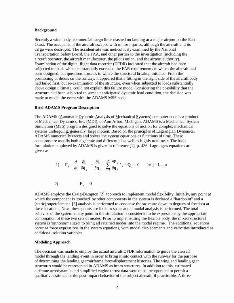
Recently a wide-body, commercial cargo liner crashed on landing at a major airport on the EastCoast. The occupants of the aircraft escaped with minor injuries, although the aircraft and itscargo were destroyed. The accident site was meticulously examined by the NationalTransportation Safety Board, the FAA, and other parties to the investigation (including theaircraft operator, the aircraft manufacturer, the pilot's union, and the airport authority).Examination of the digital flight data recorder (DFDR) indicated that the aircraft had beensubjected to loads which substantially exceeded the FAR requirements to which the aircraft hadbeen designed, but questions arose as to where the structural breakup initiated. From thepositioning of debris on the runway, it appeared that a fitting in the right side of the aircraft bodyhad failed first, but re-examination of the structure, even when subjected to loads substantiallyabove design ultimate, could not explain this failure mode. Considering the possibility that thestructure had been subjected to some unanticipated dynamic load condition, the decision wasmade to model the event with the ADAMS MSS code.
Brief ADAMS Program Description
The ADAMS (Automatic Dynamic Analysis of Mechanical Systems) computer code is a productof Mechanical Dynamics, Inc. (MDI), of Ann Arbor, Michigan. ADAMS is a Mechanical SystemSimulation (MSS) program designed to solve the equations of motion for complex mechanicalsystems undergoing, generally, large motion. Based on the principles of Lagrangian Dynamics,ADAMS numerically erects and solves the system equations as functions of time. Theseequations are usually both algebraic and differential as well as highly nonlinear. The basicformulation employed by ADAMS is given in reference [1], p. 436. Lagrange's equations aregiven as
1) ∑=
==−∂∂+
∂∂−
∂∂=
m
iji
j
i
jjj dt
d
1
n ... 1,jfor 0FLL
Qqqq
F λ&
2) Φ i = 0
ADAMS employs the Craig-Bampton [2] approach to implement modal flexibility. Initially, any point atwhich the component is 'touched' by other components in the system is declared a "hardpoint" and a(static) superelement [3] analysis is performed to condense the structure down to degrees of freedom atthese locations. Next, these points are fixed in space and a modal analysis is performed. The totalbehavior of the system at any point in the simulation is considered to be expressible by the appropriatecombination of these two sets of modes. Prior to implementing the flexible body, the mixed structuralsystem is 'orthonormalized' to bring all retained modes into the modal regime. The additional equationsoccur as force expressions in the system equations, with modal displacements and velocities introduced asadditional solution variables.
Modeling Approach
The decision was made to employ the actual aircraft DFDR information to guide the aircraftmodel through the landing event in order to bring it into contact with the runway for the purposeof determining the landing gear/airframe force-displacement histories. The wing and landing gearstructures would be represented in ADAMS as beam structures. In addition to this, estimatedairframe aerodynamic and simplified engine thrust data were to be incorporated to permit aqualitative estimate of the post-impact behavior of the subject aircraft, if practicable. A three-

3
phase approach was initially taken to model the landing event. Initially, all of the structuralcomponents were modeled as rigid. This relatively simple model permitted the kinematic systemsto be quickly verified. Next, the landing gear components were rendered flexible using theADAMS BEAM (Euler-Timoshenko formulation) element. Finally, the wings were modeledusing, again, beams, and the aerodynamic loads were distributed along them based on classical,linear aerodynamic assumptions.
Model Description
The ADAMS model is initially constructed in aircraft coordinates. At the start of the analysis, it isdynamically positioned at the runway threshold and subsequently moved in a controlled fashiondown the runway (ref. fig. 1).
Mass properties for the various components were initially supplied by the manufacturer. As thesystem was modified to incorporate flexible components in the right main landing gear and wing,the (rigid) airframe and (rigid) landing gear mass properties were modified or removed to accountfor the flexible structural mass being added. The mass, inertia values, and CG location of the(residual) rigid airframe were adjusted to bring the assembled system properties into agreementwith those initially provided by the manufacturer.
Fig. 1 Positioned Model Configuration
4
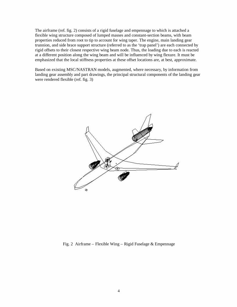
The airframe (ref. fig. 2) consists of a rigid fuselage and empennage to which is attached aflexible wing structure composed of lumped masses and constant-section beams, with beamproperties reduced from root to tip to account for wing taper. The engine, main landing geartrunnion, and side brace support structure (referred to as the ‘trap panel’) are each connected byrigid offsets to their closest respective wing beam node. Thus, the loading due to each is reactedat a different position along the wing beam and will be influenced by wing flexure. It must beemphasized that the local stiffness properties at these offset locations are, at best, approximate.
Based on existing MSC/NASTRAN models, augmented, where necessary, by information fromlanding gear assembly and part drawings, the principal structural components of the landing gearwere rendered flexible (ref. fig. 3)
Fig. 2 Airframe – Flexible Wing – Rigid Fuselage & Empennage
5
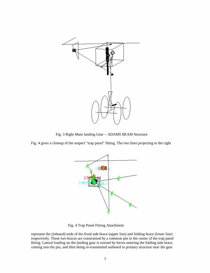
Fig. 3 Right Main landing Gear – ADAMS BEAM Structure
Fig. 4 gives a closeup of the suspect "trap panel" fitting. The two lines projecting to the right
Fig. 4 Trap Panel Fitting Attachment
represent the (inboard) ends of the fixed side brace (upper line) and folding brace (lower line)respectively. These two braces are constrained by a common pin in the center of the trap panelfitting. Lateral loading on the landing gear is reacted by forces entering the folding side brace,coming into the pin, and then being re-transmitted outboard to primary structure near the gear
6
trunnion support. The only loads intended to be reacted at the fitting are vertical. The fitting issecured to the trap panel (the closed polygon in the figure) by two 1-in diameter bolts, theoutboard one of which is a snug fit. The two bolts are modeled as a stiff, 6-component spring,located at the bolt pattern centroid.
It should be noted that this (broken) outboard bolt was one of the first pieces of debris locatednear the right main gear tire skid marks at the crash site.
A “flight path controller” (FPC) was constructed from ADAMS constraint functions to force themodel CG to follow the path determined by the aircraft flight data recorder (DFDR). The actuallanding simulation is preceded by a positioning phase in which the aircraft model is moved fromco-aligned aircraft/Earth coordinates to alignment with runway coordinates. After this initialpositioning, the X-, Y-, Z-, and Yaw-, Pitch-, and Roll position of the aircraft is forced onto themodel until the second, and critical main wheel contact, after which the aircraft is released fromthe FPC. In the actual event, the DFDR recorders "dropped out" for a more than a second after thesecond contact, presumably because of impact effects.
The elevation and heading of the runway are adjustable via constraint functions to allowadjustment of the ground contact point with respect to the DFDR information.
The position and attitude of the aircraft is dictated by the FPC up to the limit of DFDR signal.However, it is possible to release the FPC at any simulation point, after which the path of theaircraft will be determined by the forces acting upon it. Aero forces were added to permit aqualitative estimate of the aircraft behavior after the failure of the DFDR signal. Also, the wingstructure in the model is flexible, so that aero loading will effect the wing deflection and, hence,the landing gear strut loads due to the FPC-imposed motion. The aero forces are distributed to 8points on each (flexible) wing, to 4 points on each (rigid) horizontal stabilizer, and to one pointon the (rigid) vertical fin. The lift, drag, and pitching moments for each aero station are computedas an area percentage of the surface as a whole using the classical factors of area, aspect ratio, andmean aerodynamic chord. No attempt is made to vary the downwash distribution along the spans.
The tire forces are applied directly to the axle centers at the wheels. The tires are not modeled asindependent parts, thus spin up/down effects are not included. The vertical forces are applied as abi-linear spring with a stiffness of 18 kip/in up to 10 in. of tire crush, after which the stiffnessrises to 201 kip/in, simulating wheel rim contact through the tire carcass to the runway. The tireside force is applied as three components: yaw, tilt (camber), and rim force. The yaw force isinput using a manufacturer-supplied spline of force as a function of normal force, slip angle, andvelocity. The camber force is a linear function of normal force and camber angle, and the rimforce is a function of normal force and scrubbing velocity.
The axial strut force is a nonlinear function of displacement and stroking velocity. It is appliedusing three manufacturer-supplied spline functions. The piston/cylinder bearing loads are appliedusing constraints to the piston and cylinder concentric at 2 reference locations. The forcesgenerated by the concentric constraints are used to input a stroking friction force employing aconstant coefficient of friction multiplying the instantaneous, radial bearing loads and biased tooppose the stroking velocity.
The manufacturer supplied estimated attachment spring rates for the trap panel and trunnionsupport structures. These springs are input between the rigid offsets from the wing beams andtheir respective parts.

7
Simple, constant-value thrust forces, based on DFDR data, were applied along all three enginecenterlines.
Fig. 5 below shows the ADAMS model of the subject aircraft at simulation time t=6.0 sec. Theright main landing gear loads are at or near the maximum (over)load condition. The large(downward) force vector represents the reaction force applied by the fuselage trap panel to thetrap panel fitting and is consistent with the intended design function of the structure. The large(upward) vertical forces represent the (four) right main tire forces, and the curved vectorsrepresent the overturning moments applied to the outboard tires.
The results from this analysis indicated that the right main landing gear of the subject aircraft hadbeen exposed to loads that were clearly beyond the aircraft's design envelope. As a result of thisoverload condition, the landing gear support/attachment and wing structure had failed, althoughthe exact failure sequence could not be determined at this point of the accident investigation. Thisfirst phase ADAMS analysis indicated that the loads in the trap panel fitting were insufficient tocause the bolt failure evidenced at the crash scene. Examination of the wreckage indicated slightplastic bending of the front outboard axle, which gave a good estimate of the tire loads to which ithad been subjected. The tire loads predicted by the analysis were higher than this byapproximately 60%. Loads of this magnitude would have failed the bogie structure completely.Speculation arose that, either the failure had initiated elsewhere in the system, or that the coarsebeam representation of the airframe was insufficient to model the actual support conditions of thelanding gear attachment. In an effort to resolve this issue, the decision was made to replace theairframe model from the initial analysis with a more comprehensive structural representationemploying an MSC/NASTRAN-derived ADAMS FLEX_BODY element.
Fig.5 ADAMS Model of Aircraft During the (Critical) 2nd Impact

8
Enhanced Airframe Model
The MSC/NASTRAN model of the airframe was created from a combination of several differentFEA models. Shear panel/rod structures originally analyzed using the manufacturer's FEAprogram were combined with MSC/NASTRAN beam element models used for flutter analysis toyield the conglomerate analytical model shown in fig. 6 below. This effort required somereconfiguring of the FEA structures since the manufacturer's FEA code permitted the use ofisolated mid-side nodes in shear panels, a feature which has no direct MSC/NASTRANequivalent.
Fig. 6 MSC/NASTRAN Airframe Model
The center fuselage/center and inner wing structures are modeled using (predominantly) shell andbeam elements. The forward fuselage, aft fuselage and empennage, and the outer wings aremodeled using beam elements, as are the engine pylons. Where necessary, concentrated masselements are employed to maintain proper mass integrity.
After conversion from the manufacturer's FEA code to MSC/NASTRAN, modal analyses wereperformed to validate the converted structural models against accepted results for the structure.
ADAMS Modal Flexibility – Overview
The ADAMS method for rendering system components flexible is based on the Craig-Bamptonapproach [2]. Any point (e.g., GRID point or node) in a structural component which is 'touched'

9
by something else in the system is considered a 'hardpoint' and is declared a master node in anFEA static, superelement condensation. In addition to those degrees of freedom associated withthe selected hardpoints, additional, modal degrees of freedom are added from an eigenvalueanalysis performed with the hardpoints globally fixed. The possible structural deformations forthe flexible component in question consist of a combination of the geometrically orthogonalCartesian coordinates at the 'hardpoints' with the normalized, modal, eigencoordinates. Themethod restricts the behavior of the structure to the linear regime. Specifically, the deflectionsinternal to the modal structure must be small (linear geometrical assumption) and the stressesresulting from these deformations must be non-plastic (linear material assumption). Within theserestrictions, the linear structural system can be incorporated into a mechanical system simulation(MSS) undergoing gross, nonlinear motion. It is also assumed that 2nd order effects such ascentripetally-induced stress-stiffening are absent. Special methods can be employed withADAMS flexible bodies to remove the linear geometrical and stress-stiffening restrictions, butthey were not deemed necessary for this analysis. Details on the general implementation offlexible components in ADAMS are given in [4].
The end result of the conversion process in this case is a structure that is condensed down from50,000+ Cartesian coordinates to approximately 120 orthogonal coordinates.
Special ADAMS/FLEX Application
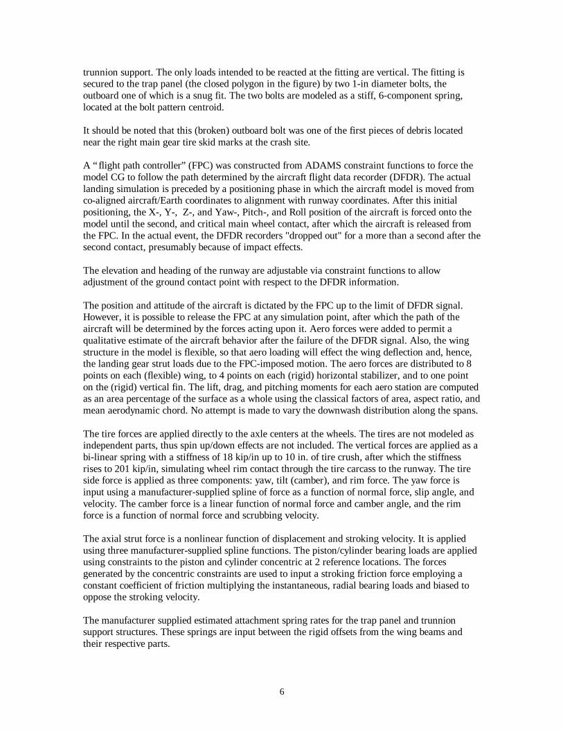
In the general case, the elastic content of the flexible structure does not, and usually cannot,change during the simulation. In this instance, however, it was desired to investigate potentialfailure sequences. It is known from the crash site investigation that the rear spar web on thesubject aircraft failed between the right main gear trunnion (or bulkhead) rib and the wing root(between wing stations 264 and 118). This failure occurred either prior to, or as a consequence of,the collapse of the right main landing gear. To represent this behavior, the airframe model wasmodified by, in effect, cutting the shear web (ref. fig. 7) in the described location vertically justinboard of the trunnion rib and horizontally from the trunnion rib to the root at the webattachment to the upper and lower spar caps. The 'cuts' introduced at these locations were thenclosed in the ADAMS analysis using very stiff springs across the (coincident) grids defining theelement boundaries. This represents a somewhat unique use of the Craig-Bampton method in thatsystem eigenmodes are combined with external restraints to modify the system behavior. Ineffect, two different, linear structures, one 'uncut' and the other 'cut', are obtained from a single,linear, self-modifying structure.
The fuse spring must be recursively triggered, i.e., it must turn off for all subsequent time, oncethe critical force level has been reached. To do this, a user-specified differential variable (anADAMS DIFF function) is specified which is forced to have a zero value until the triggeringforce level is exceeded. The value of the differential variable is ramped from zero to one over auser-specified load tolerance. This DIFF variable is used in an ADAMS STEP function tomultiply the fuse spring expression, which 'closes the loop' between the fuse trigger and the forceexpression. As long as the DIFF value remains zero, the STEP multiplier has a value of one. Assoon as the DIFF becomes greater then zero, the STEP multiplier goes to zero.
10
Fig. 7 Released Spar Web
A similar artifice was also employed to fuse the trap panel fitting to the airframe trapezoidal panelsupport structure. Use of the CAD database for the aircraft indicated that, should the fixed sidebrace pivot about its pin and reach a 'prying angle' of more than 9.1 degrees, its clevis would bindon the trap panel fitting and induce unintended bending loads in the brace. Examination of thewreckage showed that such binding had, indeed, occurred. Further, the fixed side brace had beenplastically deformed in bending by a load applied upward and backward. Classical beam analysisindicated what load was necessary to cause the onset of plastic deformation, and this load wasused to fuse the fitting.
Prior to employing the model in analysis, its modal characteristics were validated againstaccepted characteristics for the aircraft.
Analysis Results – Enhanced Model
Analysis of the enhanced model indicated that the second impact on the right main gear resultedin an overload sufficient cause the strut to bottom. The corresponding loads in the rear spar webof the wing were sufficiently above the ultimate design limit to cause failure of the web structure.Subsequent to the failure, the right wing twists substantially nose-down under the imposed loads.

11
Fig. 8 Spar Web Fracture
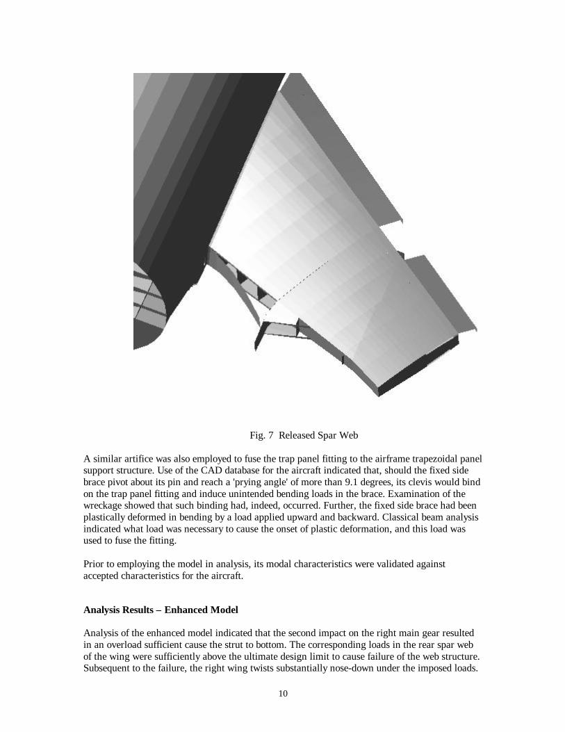
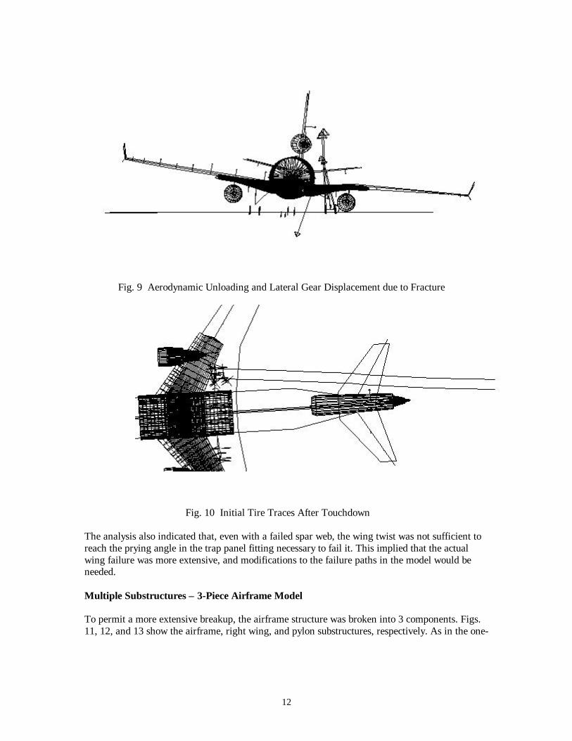
In fig. 8 the bottom edge of the failed (hence unloaded) spar web can be seen protruding belowthe wing surface, which has twisted nose-down. In effect, the wing torque box has become anexaggerated C-section, with the shear center ahead of the front spar. This twisting causes the rightwing to 'dump' most of its lift and results in a sudden and substantial outboard motion of the rightmain gear bogie, resulting from the fixed and folding landing gear side braces pivoting about their(common) attachment at the trap panel fitting (ref. fig. 9). These results are consistent with theDFDR data showing that, at this impact, the aircraft continued to roll to the right, in spite ofcontrol inputs commanding a roll to the left. Fig. 10 shows a trace of the paths of the inner andouter front tires, starting at the initial contact of the forward outboard tire and ending just after thefracture. These traces correlate very closely with the skid marks for the right main geardocumented at the crash site, inclusive of the outboard jink when the spar web fractures. Further,the right front tire loads were very close to those required for the plastic axle deformation seen atthe crash site.
12
Fig. 9 Aerodynamic Unloading and Lateral Gear Displacement due to Fracture
Fig. 10 Initial Tire Traces After Touchdown
The analysis also indicated that, even with a failed spar web, the wing twist was not sufficient toreach the prying angle in the trap panel fitting necessary to fail it. This implied that the actualwing failure was more extensive, and modifications to the failure paths in the model would beneeded.
Multiple Substructures – 3-Piece Airframe Model
To permit a more extensive breakup, the airframe structure was broken into 3 components. Figs.11, 12, and 13 show the airframe, right wing, and pylon substructures, respectively. As in the one-

13
Fig. 11 Primary Airframe Substructure
Fig. 12 Right Wing Substructure
Fig. 13 Right Engine Pylon Substructure
piece airframe model, the spar web of the right wing was cut to simulate a failure from thetrunnion rib to the root. In addition, the right wing structure was modeled to separate at thetrunnion rib, with the rib remaining with the wing. This failure path was closed by stiff springs,which were fused to fail at the same time as the rear spar web. The right pylon was attached to

14
the wing at four connection points, and the rear connection could be fused to fail should the rightnacelle contact the ground and develop a sufficient load, permitting the engine/nacelle assemblyto pivot about the front connections and allow the wing to drop to the ground. To reducemodeling turnaround time, the ADAMS RESTART feature was used to begin the analysis at timet=5.0 sec, i.e., just prior to the critical, second touchdown. Fig. 14 shows the state of the model atthis point. Subsequently, the model was restarted and the simulation extended to time t=6.68 sec.
Fig. 14 Model State at Time t=5.0 sec
(maximum). The second impact of the right main gear initiated at 5.8+ simulation seconds.Analysis indicated that, again, the right main gear was impacted with sufficient force to bottomthe strut, and that structural failure due to the overload occurred shortly thereafter. As with theone-piece model, when the wing structure fractures, the right main gear bogie moves rapidlyoutboard. Fig. 15 shows the model at simulation time t=6.4 sec, by which point the right wing hasseparated completely. At this point in the simulation, the right main gear trunnion rib has movedvertically and aft by a sufficient amount to break the trap panel fitting loose from its attachmentto the airframe. It is clear that the fixed side brace is bent upward and aft in the model, which isconsistent with the damage to the component as found at the crash site.

15
Fig. 15 Model at Time t=6.4 Sec.
Conclusions
The use of MSC/NASTRAN in conjunction with ADAMS proved very useful in determining thenature and sequence of the structural failures that occurred in the landing incident described here.The ADAMS model incorporating the MSC/NASTRAN-derived flexible structures yieldedresults that closely correlated with, both, evidence at the crash scene and generalstructural/mechanical behavior predicted by other software used in the certification of the subjectaircraft or taken from actual structural tests. The analysis was able to determine that, due to loadswell beyond the ultimate limits to which the aircraft had been designed, the failure of thestructure had originated at the rear spar web of the wing and not, as originally thought, at theinboard trap panel fitting. The use of non-linear, external forces at the boundaries of linear elasticstructures was successful in producing different, linear states from a single linear model.
Acknowledgements
The authors wish to thank B. Black, V. Bui, J. Cybulski, J. Galligher, N. Gilleran, S. Jinadasa, A. Kernik,E. Kubota, H. Ngo, M. Shen, E. Smith, and W, Steelhammer of Boeing; A. Meyer and C. Tong, formerly ofBoeing; and D. Riesland of MDI for their contributions to the accomplishment of this work.
BIBLIOGRAPHY
1) Principles of Mechanics, Synge, John L. and B. A. Griffith, McGraw Hill BookCompany, 1959.
2) "Coupling of Substructures for Dynamic Analyses", Craig, R. R. Jr., and M. C. C.Bampton, AIAA Journal Vol. 6, No. 7, Jul/68, pg. 1313-1319.
3) MSC MSC/NASTRAN Superelement Analysis SEMINAR NOTES, anon., MacNeal-Schwendler Corp., Los Angeles, CA, 1994
4) Using ADAMS/Flex, anon., Mechanical Dynamics, Inc., Ann Arbor, MI, 1998.