Embed Size (px)
Citation preview

Industrial Engineering Letters www.iiste.org
ISSN 2224-6096 (Paper) ISSN 2225-0581 (online)
Vol.4, No.3, 2014
67
The Combustion and Interchangeability of Natural Gas on
Domestic Burners
TOBINSON BRIGGS Mechanical Engineering Department, Faculty Of Engineering, University Of Port Harcourt
East-West,Choba,Port Harcourt, Nigeria. E-mail: [email protected]
Abstract
The burning characteristics of natural gas and the determination of its inter-changeability with liquefied petroleum gas on domestic burners are presented in this paper. Earlier studies had sought the correlation of heating values with specific gravities as a basis for determining the interchangeability of the gas. In this study, it is established that, additionally burning characteristics, which depend on chemical composition, must also be included to accurately predict the range of interchangeability achievable in a given situation. The Wobbe Number, combustion potential and yellow tip index are calculated for both liquefied petroleum gas (LPG) and various compositions representative of associated low-pressure and non-association high pressure natural gas. These were then graphically presented as area enclosed by lines representing limits of flash back, lifting and incomplete combustion. It is found that natural gas can be interchanged with LPG as substitute gas for domestic burners, without adjustment of the burner nozzle. The necessary condition for this is that the quality of combustion for the associated natural gas is enhanced when it is fed into the burner above the hydrocarbon and water dew points of the gas, and at twice the pressure at which bottled liquefied petroleum gas is usually supplied to the burners. Keywords: Natural gas, liquefied petroleum gas (LPG), burning characteristics, Wobbe Number, combustion potential and yellow tip index 1. INTRODUCTION
Natural gas provides about one fifth of all the world’s primary energy requirements. This remarkable development has taken place in many countries as a result of the construction of long-distance large diameter steel pipelines which have brought large volumes of gaseous fuel to domestic, commercial and industrial users many miles away from the field themselves. In order to understand the safe storage handling and utilization of any commodity, it is first essential to understand the nature of the material under consideration. Natural gas varies in composition from mixture of almost pure hydrocarbons; with impurities, mainly nitrogen (N2), hydrogen sulphide (H2S), and carbon dioxide (CO2). Gases containing significant amounts of H2S or CO2 or both are called sour or acid gases. These impurities must be removed before the gas is used as a fuel. The hydrocarbon gases are methane, ethane, propane, butanes, pentanes, and small amounts of hexanes, heptanes, and some heavier fractions. In gas used fuel, methane is the largest components usually 85 to 98%. Gas is normally considered to be a mixture of straight chain or paraffin hydrocarbon compounds. However, occasionally cyclic and aromatic compounds occur in natural gas. Although substantial quantities of natural gas so far discovered are found in association with crude oil, the bulk however, is not associated. The term associated gas is applied to that produced by the stabilization of crude oil; in other words, it is the gas in excess of that which can be carried in the crude at atmospheric-pressure. Although associated gases consist mainly of methane and ethane, they nevertheless contain appreciable quantities of C3 and higher hydrocarbons and are a major source of liquefied petroleum gas. Non-associated natural gas may be either dry or may require treatment for the removal of condensate before distribution. In both cases the highly predominant hydrocarbons present will be methane and ethane. 2 GAS COMPOSITION
The natural composition of natural gas can vary over wide range. Even two wells producing from the same reservoir may have different compositions. Figure 1 shows different types of reservoirs with their typical hydrocarbon compositions of the gas produced from them. The composition of the gas produced from a given reservoir may change with time if liquids condense in the reservoir as pressure declines. This occurs in the so called retrograde reservoir. Although natural gases contain small fractions of hydrocarbon components much
heavier than heptane, most analyses group of the heavier components into a category called heptanes plus or +
7C
Industrial Engineering Letters www.iiste.org
ISSN 2224-6096 (Paper) ISSN 2225-0581 (online)
Vol.4, No.3, 2014
68
Table 1: Types of reservoirs with their typical hydrocarbon compositions of the gas produced from them
COMPONENT SYMBOL MOLE
WEIGHT
MOLE PERCENTAGE ASSOCIATED
GAS NON ASS0CIATED GAS
WET GAS DRY GAS Methane CH4 16 85.81 59.52 97.17 Ethane C2H6 30 6.41 5.36 1.89 Propane C3H8 44 3.33 4.71 0.29 i-Buthane C4H10 58 1.28 2.03 0.13 n-Butane C4H10 58 1.03 2.39 0.12 i-Pentane C5H12 72 0.43 1.80 0.07 n-Pentane C5H12 72 0.25 1.61 0.85 Hexane C6H14 86 0.32 2.60 0.04 Heptanes Plus +
7C H16 100 0.38 19.68 0.24
Nitrogen N2 28 0.073 0.00 0.00 Carbon dioxide CO2 44 0.68 0.00 0.00 100.00 100.00 100.00
3 ATMOSPHERIC BURNERS
Practically all domestic and commercial gas appliances and many industrial gas units employ atmospheric burners. Undoubtedly, more burners of this type are in use than any other kind. In an atmospheric gas burner the momentum of the jet of gas entrains, from the atmosphere, a portion or all the air required for combustion. Air premixed with the gas is designated as primary air and the remainder supplied around the flame as secondary air. The various parts of a domestic atmospheric gas burner are shown in Figure. 2. Low pressure gas flows through the injector (gas orifice) at a fairly high velocity. The stream of gas leaving the injector draws air through primary air openings into the mixing tube. Gas and air are mixed in this mixing tube and the gas-air mixture passes through the burner ports on the burner head, where it burns upon ignition. The conversion of low-pressure self-aerated burner, in its simplest form, involves reduction for two purposes, in the primary-jet aperture area. The first, to allow for higher Wobbe Number (W2) of natural gas, would involve reducing the orifice area roughly inverse ratio to the Wobbe number change (i.e. W1/W2). This would maintain the thermal discharge at the pressure P1 used for the high-flame speed gas. This pressure must now be increased to P2 (i.e. the increased pressure) so that the gas modulus is maintained constant in order to maintain unchanged the pre-aeration:
2
2
1
1
W
P
W
PM == (1)
This means that the orifice pressure must be increased directly as the square of the Wobbe Number change:
2
1
2
1
2 )(W
W
P
P= (2)
Since the gas discharge is proportional to the square root of this pressure, this would involve an increase in
thermal output in the proportion )(1
2W
W, to correct this, a second reduction in the primary-jet area, roughly in

Industrial Engineering Letters www.iiste.org
ISSN 2224-6096 (Paper) ISSN 2225-0581 (online)
Vol.4, No.3, 2014
69
inverse ratio to the change in Wobbe Number, would be required. These changes in the area of the primary jet arise from the higher Wobbe Number of natural gas. If natural gas/air or LPG/air is used, of a Wobbe Number equal to that of the high-flame-speed gas replaced, no change is necessary on the other hand if undiluted LPG vapour is used, a greater reduction in primary-jet area is demanded, since LPG Wobbe Number exceeds those of natural gas. With the delivery to the flame-port area of the same thermal equivalent of natural gas, with the same proportion of its stoichiometric air as for former high-flame-speed gas supply, there remains the great difference in flame speed, which results in the flames leaving the burner unless action is taken to avoid it. This action normally takes either or both of the forms of an increase in the flame-port area, or the introduction of flame-stabilization devices. Finally, stable natural gas flame having been produced of corresponding thermal output of that of high-flame-speed gas the issue arises of whether there is sufficient combustion rate of the LPG, or natural gas. If there is not, it may be possible to achieve it by redesign of burner.
4. THERMAL CONSIDERATIONS
The amount of gas supplied to the burner and the heating value of the gas governs the heat input to the burner. At relatively low pressure and at small pressure differences over the nozzle for a low Reynolds number flow, typical of domestic gas burners (Re<500), Dobelin (1966) suggests the use of the equation:
2
2
1ggf VCdP = (3)
Where: Pf = the pressure difference across the injector; this the difference in gas pressure (Pg), for atmospheric domestic burners and the atmospheric pressure (Pa); dg = the gas density; Vg = the injector jet velocity; C = a correction factor to account for viscous effect resulting in flow contraction of the injector tip. The correction factor C is determined from C = 1 + 4/Re in the range 10<Re < 400. Equation (3) is valid for cylindrical injectors. The Reynolds number is defined with respect to the injector tip internal radius and gas velocity. Rosenhead (1963) suggested the correction for injectors of special shapes at Re <40. The injector jet velocity is obtained from equation 3 as:
21
2
=
g
f
gCd
PV (4)
The corresponding gas discharge rate is:

Industrial Engineering Letters www.iiste.org
ISSN 2224-6096 (Paper) ISSN 2225-0581 (online)
Vol.4, No.3, 2014
70
21
2
==
g
f
ogogCd
PAVAQ (5)
The amount of gas of heating value H discharging through an injector of area oA , corresponds to the thermal
input for a given burner. Thermal input is given as:
21
2
=
g
f
othCd
PHAQ (6)
In actual practice, the pressure in the gas system is regulated to a constant domestic supply pressure. Thus, the pressure difference (Pf) is independent of changes in the temperature of the gas, and may be taken as constant. Equation (6) becomes:
21
21
2−
=
a
g
a
f
othd
d
Cd
PHAQ (7)
Now, denoting the constant KCd
PHA
a
f
o =
21
2 and the specific gravity of the gas S
d
d
a
g= , equation 6 is re-
written in the form:
21−
= KHSQth (8)
If the heating values of the gas or its density, or both are changed, the thermal input of the burner remains
constant as long as the ration 21−
HS remains constant, which is stated by equation (8). This ratio is known as the Wobbe Number (W) and it depends only on the gas composition. Nevertheless, it does not necessarily means that the burner will perform satisfactorily for all gases with the same Wobbe Number since other characteristics for particular gas composition may be different from the characteristics of other gas compositions. The Wobbe Number of natural gas of a given composition of N constituent gases (i) may be determined from the relationship:
2
12
1
1
==
∑
∑−
ii
a
N
ii
MXM
HX
HSW (9)
Where: Mi = the molecular weight of constituent (i); Hi = the heating value of constituent (i) Xi = the volume fraction or mole fraction; Ma = the molecular weight of air = 28.964kg. Equation (9) is used to determine the Wobbe Number of low-pressure natural gas, non associated high-pressure natural gas and liquefied Petroleum Gas (LPG). The calculation for the gross calorific value H of L.P natural gas and H.P gas are tabulated with the molecular weight of the gases.

Industrial Engineering Letters www.iiste.org
ISSN 2224-6096 (Paper) ISSN 2225-0581 (online)
Vol.4, No.3, 2014
71
Table2: The gross calorific value H of L.P and H.P Natural gas with their molecular weight.
Composition
Mi
Hi J/m3
Low-pressure Natural gas
High pressure Natural Gas
iα iiMα iiHα iα iiMα iiHα
CH4 16 3.85x10⁷ 0.85810 13.7296 3.3037x10⁷ 0.9717 15.5472 3.7400x10⁷ C2H6 30 6.74x10⁷ 0.06410 1.9230 0.4320x10⁷ 0.0189 0.5670 0.1270x10⁷ C3H8 44 5.59x10⁷ 0.03330 1.4652 0.1862x10⁷ 0.0029 0.1276 0.0160x10⁷ n-C4H10 58 12.43x10⁷ 0.01030 0.5974 0.1280x10⁷ 0.0012 0.0696 0.0149x10⁷ i-C4H10 58 12.39x10⁷ 0.01280 0.7424 0.1590x10⁷ 0.0013 0.0754 0.0161x10⁷ n-C5H12 72 15.28x10⁷ 0.00250 0.1800 0.0382x10⁷ 0.0005 0.0360 0.0076x10⁷ i-C5H12 72 15.24x10⁷ 0.00430 0.3096 0.0655x10⁷ 0.0007 0.0504 0.1076x10⁷ C6H14 86 18.12x10⁷ 0.00320 0.2752 0.5798x10⁷ 0.0004 0.0344 0.0073x10⁷
100 - 0.00380 0.3800 - 0.0024 0.2400 - N2 28 - 0.00073 0.2044 - 0.0000 0.0000 - CO2 44 - 0.00680 0.2992 - 0.0000 0.0000 - 20.1060 4.3702x10
7 16.7480 3.941x10
7
Computed values of H and the molecular weight of the LPG gas composition considered are tabulated. Table 3: values of H and the molecular weight of the LPG gas composition considered
Composition Symbol Mole % Mi Hi J/m3 iα iiMα iiHα
Ethane C2H6 2.60 30 3.850x10⁷ 0.0260 0.7800 0.100x10⁷ Propane C3H8 48.65 44 3.279x10⁷ 0.4865 21.4060 3.279x10⁷ Butane C4H10 48.65 58 12.43x10⁷ 0.4865 28.2170 6.047x10⁷ Nitrogen N2 0.10 28 - 0.0010 0.0280 - 50.4310 9.426x10
7
Now, applying equation (9) for LP natural gas Wobbe Number:
2
1
72
1
964.28
106.10
103702.4
==− x
HSW = 52452687 = 52452.7x107
Wobbe Number for H.P natural gas:
2
1
72
1
964.28
748.16
109412.3
==− x
HSW = 51829410 = 51829.4 x 103
Wobbe number for LPG gas:
2
1
72
1
964.28
431.50
1042634.9
==− x
HSW = 71436758 = 71436.7 x103
The Wobbe number computed with the aid of the above expressions are 71436.7x103, 51829.4x103 and 52452.7x103 for LPG, high pressure natural gas and low pressure natural gas respectively. 5 COMBUSTION REACTION
In most combustion processes, atmospheric air rather than oxygen is used as an oxidizer. Atmospheric air, on molar basis, is composed of approximately 21 percent oxygen, 3.76 mole of nitrogen are involved when air is used as an oxidizer in place of oxygen.

Industrial Engineering Letters www.iiste.org
ISSN 2224-6096 (Paper) ISSN 2225-0581 (online)
Vol.4, No.3, 2014
72
The air used during the combustion process is theoretically just sufficient for complete combustion of the entire carbon and hydrogen present in the fuel. The amount of air used in this process is called the “theoretical” or “stoichiometric air”. The ratio of the mass of stoichiometric air to the mass of fuel is called the theoretical or the soichiometric air-fuel ratio. To calculate the amount of air required in methane and other gas components of natural gas, their stoichiometric equation for complete combustion are written as: CH4+2[O2+3.76N2] →CO2+2H2O+7.52N2 9.52 vol. of air = 1 vol. of CH4 C2H6+3.5[O2+3.76N2] →2CO2+3H2O+13.16N2 1 vol of C2H6 = 16.66 vol. of air C3H8+5[O2+3.76N2] →3CO2+4H2O+18.75N2 1 vol of C3H8 = 23.8 vol. of air 2C4H10+13[O2+3.76N2] →8CO2+10H2O+48.88N2
1 vol of C4H10 = 30.94 vol of air C5H12+8[02+3.76N2] →5C02+6H20+30.08N2
1 vol. of air C5H12 = 30.08 vol. of air C6H14+9.5[O2+3.76N2] →6CO2+7H2O+35.72N2
1 vol. of C6H14 = 45.22 vol. of air C7H16+11[O2+3.76N2] →7CO2+8H2O+41.36N2
1 vol. of C7H16 = 52.36 vol. of air Weighted volume of air required for complete combustion using volume fraction of each component of the natural gas: (0.8581x9.51)+(0.0641x16.66)+(0.0641x16.66)+(0.0333x23.8)+(0.0128x30.94)+(0.0103x30.94)+(0.0043x38.08)+(0.0025x38.08)+(0.0032x45.22)+(0.0038x52.36) = 8.169+1.068+0.793+0.396+0.319+0.167+0.095+0.245+0.199 = 11.351 The required volume of air for complete combustion is 11.351 volume of air. Therefore, repeating the above procedure to calculate the volume of air for incomplete combustion gives: 3CH4+2[O2+3.76N2] →CO+CO2+H2O+2H2+CH4+7.5N2
∴1 vol. of fuel = 3.17 vol. of air 2C2H6+2[O2+3.76N2] →CO+CO2+H2O+2H2+C2H6+7.52N2
∴1 vol. of fuel = 4.76 vol. of air 3C3H8+4[O2+3.76N2] →5CO+CO2+H2O+7H2+C3H8+15.04N2
∴1 vol. of fuel = 6.35 vol. of air 2C4H10+3[O2+3.76N2] →3CO+CO2+H2O+4H2+C4H10+11.28N2
∴1 vol. of fuel = 7.14 vol. of air 2C5H12+3.5[O2+3.76N2] →4CO+CO2+H2O+5H2+C5H12+13.16N2
∴1 vol. of fuel = 8.33 vol. of air 2C6H14+4[O2+3.76N2] →5CO+CO2+H2O+6H2+C5H12+15.04N2
∴1 vol. of fuel = 9.52 vol. of air

Industrial Engineering Letters www.iiste.org
ISSN 2224-6096 (Paper) ISSN 2225-0581 (online)
Vol.4, No.3, 2014
73
2C7H16+4.5[02+3.76N2] →6CO+CO2+H2O+7H2+C7H16+16.92N2
∴1 vol. of fuel = 10.71 vol. of air Weighted volume of air required for incomplete combustion using volume fraction of each component of the natural gas:
(0.8581x3.17)+(0.0641x4.76)+(0.333x6.35)+(0.128x7.14)+(0.0103x7.14)+(0.0043x8.33)+ (0.0025x8.33)+(0.0032x9.52)+(0.0038x10.71) = 2.720+0.305+0.212+0.091+0.074+0.036+0.021+0.031+0.041 = 3.544 ≈ 4.00
The volume of air required for incomplete combustion is 4 volumes to 1 volume of fuel. The equivalent ratio (φ )
is a useful quantity specifying the richness or leanness of the mixture. It is defined as:
( )( )
tricstoichiome
actual
oxidizerfuel
oxidizerfuel
/
/=φ (10)
Hence: ( )
( ) 838.2
352.111
41
==φ
Since, φ is greater than unity, the mixture is very rich, with less than stoichiometric amount of air available to
burn the fuel. Considering the combustion of methane CH4 which is the principal constituent of natural gas, the equation for partial combustion of CH4 is written as: CH4+x [O2+3.76N2] →n1CH4+n2CO+n3CO2+n4H2O+n5H2+ 3.76xN2
x
ratioair
fuel76.4
1=
And equation for complete combustion of CH4 is written as: CH4+2[O2+3.76N2] →CO2+2H2+C7H16+7.52N2
52.9
1=
tricstoichiomeair
fuel
Hence, ( ) ( )52.91
76.41
x=φ
7047.0=∴ x Restating the partial combustion of CH4 nCH4+x [O2+3.76N2] →n1CH4+n2CO+n3CO2+n4H2O+n5H2+ 3.76xN2
Also, consider equilibrium of water-gas reaction written as: CO + H2O = CO2+H2 With the limit of: H2/H2O = 0.33; and CO/CO2 = 0.02 for legislative standard. Applying carbon balance: n = n1 + n2 + n3 Oxygen balance: 2x = n2 + 2n3 + n4 Hydrogen balance: 4n = 4n1 + 2n2 + 2n5
Finally, the nitrogen balance is made. Since nitrogen does not take part in the combustion process, its value remains the same throughout: 3.76 x N2 = 3.76 x N2 Recall:
454
5
2
2 33.033.0 nnn
n
OH
H=⇒==
323
2
2
02.0;02.0 nnn
n
CO
CO=⇒==

Industrial Engineering Letters www.iiste.org
ISSN 2224-6096 (Paper) ISSN 2225-0581 (online)
Vol.4, No.3, 2014
74
Substituting 7047.0;02.0 32 == xnn and n = 1 into carbon balance and oxygen balance equations, the
equations becomes:
31 02.11 nn −= (i)
4302.2409.1 nn += (ii)
Also substituting 4531 33.0,02.11 nnnn =−= and n = 1 into hydrogen balance equation becomes:
43 66.208.40 nn +−= (iii)
Solving equations (ii) and (iii) simultaneously by multiplying equation (ii) by 2.66 and equation (iii) by 1, yields:
397.0453.9
748.33 ==∴n
Therefore: n4 = 0.609 from equation (iii) n1 = 0.595 from equation (i) n2 = 0.02n3 = 0.02 x 0.397 = 0.008 The stoichiometric equation for incomplete combustion takes the form: CH4+0.705[O2+3.76N2] →0.595CH4+0.008CO+0.397CO2+0.609H2O+0.201H2+ 2.650N2
The molecular weight of product mixtures given by this equation and is calculated as follows:
iimM ∑= α (11)
Where:
iα = mole fraction or volume fraction;
im = the molecular weight of the product constituent (i)
22224
2846.4
650.22
46.4
201.018
46.4
609.044
46.4
397.028
46.4
008.016
46.4
595.0
000 NHHCCCH
xxxxxxM
+
+
+
+
+
=
= 2.135 + 0.050 +3.917 + 2.458 + 0.090 + 16.638 = 25.288 The mass fractions of product mixture are considered too. The equations for these are:
M
mF ii
i
α= (12)
0020.0288.25
0508.0==COF
0844.0288.25
135.14
==CHF
1549.0288.25
917.32
==COF
0972.0288.25
458.22
==OHF
0036.0288.25
090.02
==HF

Industrial Engineering Letters www.iiste.org
ISSN 2224-6096 (Paper) ISSN 2225-0581 (online)
Vol.4, No.3, 2014
75
6579.0288.25
638.162
==NF
∑ = 0000.1F
Since >φ unity, some of the C and H necessarily appear as CO and H2 in the burned gas the mixture is said to
be rich. The computed value of the mass fraction of product mixture shows that an appreciable amount of inert such as N2 and CO2 are present in the gas. On the other hand the combustion potential can be increased considerably when H2 is present in quantities not exceeding 10% in the gas, without risk of flashback. 6. ENERGY EQUATION
If the products of any combustion process or of any chemical reaction are at equilibrium and uniform with respect to composition, pressure, and temperature (whether or not the reactant mixture is uniform), and if there are no heat losses to the surrounding in the process, the thermodynamically attainable temperature is calculated as the adiabatic flame temperature Ta. In addition, if the process occurs at constant pressure, the overall enthalpy change is zero, and Ta is the temperature that satisfied the condition. From a uniform initial temperature To (298K) the first law of thermodynamics for such a reaction becomes: HP = HR (13) Where HP = enthalpy of the product mixture HR = enthalpy of the reactants
i.e., 0)(00
=−+∑ iTTiT HHnHa
, product at Ta
The first term is the enthalpy change at T0 per mole of fuel for a combustion reaction written with products that corresponds to thermodynamic equilibrium at Ta. The sum is the enthalpy of the burned gas mixture at equilibrium relative to its value at T0. For the incomplete combustion analysed above, the enthalpy equation becomes:
22298 HHCOCOff
T
p FFHFHFdTCa
−−=∫ (14)
Where:
ipip CFC =
And; iF = mass fraction of constituent (i)
fF = mass fraction of fuel
COF = mass fraction of CO
2HF = mass of fraction of H2
ipC = specific heat of constituent (i)
pC = mean specific heat for the product
The specific heats of the product gases are calculated as follows:
TCCHp
432.127624
+=
TCCOp
1734.0996 +=
TCOHp
6409.016432
+=
TCHp
764.1134002
+=
TCNp
1725.09.9832
+=

Industrial Engineering Letters www.iiste.org
ISSN 2224-6096 (Paper) ISSN 2225-0581 (online)
Vol.4, No.3, 2014
76
Hence: TCp 346.063.1232 +=
The calorific value of heating value of CH4, CO, and H2 are 5.0 x 10⁷ KJ/Kg, 1.0 x 10⁷ KJ/Kg, and 12.0 x 10⁷
KJ/Kg respectively. i.e.
( ) ( ) ( ) ( )
( ) ( )( ) 376800298346.02
129863.1232
10120036.0100.1002.0100.50844.0346.063.1232
22
777
298
=−+−
−−=+∫
aa
T
TT
xxxdTTa
37680083.38268663.1232173.0 2 =−+ aa TT
083.415068663.1232173.0 2 =−+ aa TT
042.2399240903.71252 =−+ aa TT
Since, the equation is quadratic the roots of the equation are given as -9619.24 and 2494.21 for aT values.
Consider aT value as 2494.21K, which turns out be high for the input composition, rich fuel, and the flame
containing unhurt hydrocarbon; in effect the endothermic dissociation of, e.g. CO2 and H2O, leads to significant equilibrium partial pressures of other species (OH, H, O, O2, H2 and CO) that simultaneously satisfy the equilibria:
22222 2
1,
2
1OHOHHOHOH +=+=
HHandOOOCOCO2
1
2
1
2
1,
2
12222 ==+=
Excess air will revert the dissociated carbon dioxide to its equilibrium state. 7. PERFORMANCE CRITERIA
Satisfactory behaviour with respect to flash back, blow off, and heating capability, generally requires responsibility as nearly as possible of the maximum temperature and velocity of the burned gas; and of the shape or height of the flame cone. Often this must be done precisely, and with no changes in orifices or adjustments in the feed system. A set of flame limiting conditions, i.e., a point within the stable flame zone, as function of primary aeration and gas input rate may be established for any given aerated burner. These flame limits will vary with the composition of the gas supplied. With a substitute gas, the primary air and gas input rate may change, depending on the relative specific gravities and heating values of the two gases involved (natural gas and LPG gas). However, for the substitute gas (natural gas) to be interchangeable with the base gas (LPG gas), the base setting of primary air and input rate must be within the flame limits of the substitute gas. Figure 3 illustrates these principles. It presents typical flame limit curves of a reference burner on an adjustment gas (Subscript a) and a substitute gas (subscript s): (1) Curve Ls is the lifting limit curve for the substitute gas (Natural gas). It is above La, hence, the substitute gas is burns faster than the adjustment gas. (2) Curve Ys is the yellow tipping limit for the substitute gas; curve Ya is the yellow tip limit of the adjustment gas. Since Ya is below Ys, the adjustment gas, has less yellow tipping constituents. (3) Curves Fs and Fa show flashback limits of the substitute and adjustment gases respectively. The substitute gas is susceptible to flashback, as indicated by curve Fs extending further to the right. Satisfactorily and stable flames will, therefore, result with the adjustment gas for any burner adjustment of primary air and input rate within the zone bounded by the limit curves La, Ya and Fa. However, after initial satisfactory adjustment on gas “a”, substitution of gas “s” will cause a shift in primary aeration and input rate, which must now be within the limit curves Ls, Ys, and Fs for acceptable interchange.

Industrial Engineering Letters www.iiste.org
ISSN 2224-6096 (Paper) ISSN 2225-0581 (online)
Vol.4, No.3, 2014
77
Figure 3: A reference burner performance diagram for adjustment gas (a), and substitute gas (s)
Figure 3 also determines the limits of adjustment on gas “a”, which will also satisfy substitute gas “s”. These adjustments on gas “a” fall on the upper dotted line. This dotted line was determined by selecting a series of points on Ls and, in the foregoing manner, calculating adjustments on gas “a”, which would give the selected points on substitute gas “s”. Thus, this dotted line is the upper limit of adjustment on gas “a” for satisfactory substitution of gas “s”. Any adjustment on gas “a” above the dotted line will produce lifting flame when gas “s” is substituted. Similarly, the lower flame limit for adjustment on gas “a” for satisfactory substitution of gas “s” may be determined. Points on curve Ys were used to locate the lower dotted line in figure. 3. Flashback curves may also be treated in the same manner. In this case, they are outside the limits of practical burner adjustments. Figure 3 shows that gas “s” may be substituted for gas “a”, if the initial adjustments on gas “a”, are made within the dotted lines. It also indicates what changes in adjustment may be necessary to make gas s interchangeable. For example if a burner were adjusted on gas “a”, at point a, the resulting adjustment after substitution of gas “s” would be at point s. since point s is below Ys, flames would be yellow tipped. For satisfactory performance, increased primary aeration would be necessary so as to locate the initial adjustment at point a1. The resulting adjustment on substitution would then be at point s1 above Ys. These examples also show that inter-changeability of gases cannot be predicted entirely from their characteristics. It is also noted that the type of burner adjustments made greatly influences inter-changeability. If typical adjustment for a given situation fell below the lower dotted line in Figure 3, gas “s” could not be considered a satisfactory substitute unless readjustments were made; but if, on the other hand, typical adjustments fell entirely between the dotted lines, it could be considered a satisfactory substitute. Figure 3 also shows that inter-changeability of gases is not always reversible. From these curves, any adjustment between the limits of Ls and Ys would be satisfactory on gas “s” with initial adjustment made on it. Substitution of gas “a” for gas “s” then would result in adjustments somewhere between the dotted lines. Because these lines are entirely within the limits of La and Ya, gas “a”, could be satisfactorily substituted for gas “s”. however, as previously shown, gas “s” could not be substituted for gas “a”, if initial adjustments on gas “a”, were below the

Industrial Engineering Letters www.iiste.org
ISSN 2224-6096 (Paper) ISSN 2225-0581 (online)
Vol.4, No.3, 2014
78
lower dotted line and above the upper dotted line. The performance diagram of Figure 3 is for a particular reference burner. Analysis of an inter-changeability problem is more accurate and complete if it includes performance diagrams of several critical burners on the line, since burner design influences inter-changeability. Of the design of the reference burner were modified to raise the lifting limits appreciably without affecting the yellow tip limits, the burner would have greater flexibility and, hence, would tolerate a greater variation in substitute gas composition. Since the abscissa of Figure 3 denotes input per square inch of port area rather than simply input rates, the diagram is applicable to a wide variety of burners having the same pattern of port design and arrangement as the reference burner although varying in the relative proportions of their component ports. Similar performance diagrams of a few critical burners would, therefore, provide a fair accurate analysis of a system’s inter-changeability problem. 8. PERFORMANCE CRITERIA BY KNOY FORMULA
The assumption that the burner head mixture of primary air and gas has a heating value of 0.65 x 10⁷ J/m3 when an atmospheric burner is properly adjusted yields equation (15), which is plotted in Figure 4. For good inter-changeability, the substitute gas determined from this chart should have C value equal to that of the adjustment gas. A deviation of ± 5 percent may be tolerated in some cases. Furthermore, a deviation of ± 10 percent from the mixture heating value of 0.653 x 10⁷ J/m3 yields a C factor for a substitute gas above that of the adjustment gas thereby indicating softer flames.
( )
5.0
71065.0
G
xHC
−= (15)
Where: C = a constant H = heating value of gas, J/m3 G = specific gravity of gas (air = 1.0) Figure 4 and equation (15) have the advantages of simplicity and ready availability of the data required. These are important factors in meeting emergencies with substitute gases of diverse properties in proportions varying so rapidly that only heating value and specific gravity can be known at all times.

Industrial Engineering Letters www.iiste.org
ISSN 2224-6096 (Paper) ISSN 2225-0581 (online)
Vol.4, No.3, 2014
79
Figure 4: Knoy inter-changeability chart
Both equation (15) and Figure 4 are based on heating value and specific gravity relations and provide no means for evaluating burning characteristics of a substitute gas. Without duly allowing for such characteristics misleading result might be obtained. Criteria have been described by Knoy chart, some test burners will ensure as good substitute gas performance as is possible with available equipment and materials. Flame limit curves like those in Figure 5 are treated in the same manner as those in Figure 3. Inter-changeability is indicated by whether or not the zone of adjustment on substitution lies within the region of stable flames as established by the flame limit curves of the substitute gas.

Industrial Engineering Letters www.iiste.org
ISSN 2224-6096 (Paper) ISSN 2225-0581 (online)
Vol.4, No.3, 2014
80
Figure 5: Flame stability diagram for methane showing blow-off, flashback, and the effects of port size on
yellow tipping (Tubes of diameters shown use as burners).
9 BURNER AERATION
The achievement of adequate mixing of the gas with the correct amount of air is required for the gas used as a fuel for the domestic burner in order to burn safely and satisfactorily without formation of dangerously poisonous gases such as carbon monoxide, nitric and nitrous oxides, unburned hydrocarbons, and ash. The part of air necessary for complete combustion of the gas is entrained by the gas as primary air. The ratio between primary air and total amount of air required for complete combustion is called aeration factor (e). To a first approximation, using the injector theory, Kentfield and Barnes (1972) give the primary air/gas ratio (n) independent of the gas pressure. Since the aerated burner works on the principle of primary air aspiration by injection this ratio is given by:
r
SKn
2
1
1= (16)
Where K1 is constant and r is the radius of the injector bore. Restating the partial combustion equation written as: CH4+0.705[O2+3.76N2] →0.595CH4+0.008CO+0.397CO2+0.609H2O+0.201H2+2.65N2
1 volume of gas = 3.36 volume of air

Industrial Engineering Letters www.iiste.org
ISSN 2224-6096 (Paper) ISSN 2225-0581 (online)
Vol.4, No.3, 2014
81
∴primary 36.3=nratiogas
air
From analysis of compound gaseous fuel Maleev established that on volume basis, theoretical air/gas ratio (M) is roughly proportional to the heating value of the gas. Thus:
HKM 2= (17)
Where: K2 is constant and H is heating value of the gas. The theoretical air-fuel ratio on volume basis can be obtained from the complete combustion equation of methane, the main component of natural gas as: CH4+2[O2+3.76N2] →CO2+2H2O+0.201H2+7.52N2
1 volume of CH4 = 9.52 volumes of air
∴ theoretical 1
52.9=Mratio
gas
air
Combination of equations 16 and 17 yields:
r
S
K
K
m
ne
2
1
2
1 .== (18)
That is:
353.052.9
36.3==e
From equation (18) it can be seen that the aeration factor (e) is inversely proportional to the Wobbe Number of the gas, as long as the same injector jet bore is used. 10 COMBUSTION POTENTIAL
The combustion potential is an empirical method for predicting the inter-changeability between gases of different compositions in terms of the tolerable limits of variations of the relevant gas properties. The combustion potential (C) of the gas of given composition is calculated from a modified version of the original equation by Delbough (1996) in the form:
2
1
=∑
c
iiic S
SCXC (19)
Where: Ci = the combustion potential of the gas constituent (i)
Si = specific gravity of pure hydrocarbon gas constituent (i) Sc = specific gravity of the gas, corrected for CO, CO2, N2 and O2 Xic = the mole fraction of hydrocarbon constituent (i) in the gas corrected for CO, CO2 N2 and O2
Let the volume fractions of CO, CO2, N2 and O2 be COX ,2COX ,
2NX , and 2OX respectively.
The corrected volume fraction (Xic) of the pure hydrocarbon constituent (i) is then given by:
( )
2221 ONCOCO
iic
XXXX
XX
−−−−= (20)
Therefore:
iiC
a
C MXM
S ∑=1
(21)
The combustion potential (Ci) for constituent (i) is determined from the empirical relation:

Industrial Engineering Letters www.iiste.org
ISSN 2224-6096 (Paper) ISSN 2225-0581 (online)
Vol.4, No.3, 2014
82
( )
2
1
100
C
ii
S
xaC = (22)
For methane (CH4) ai = 0.3; while for the other pure saturated hydrocarbons (alkanes), ai is correlated with Mi according to the expression.
iMa
3.2146.11 −= (23)
From the above expressions, the computed specific gravity (corrected for C02 and N2) of low pressure and high
pressure natural gas are 0.6819 and 0.5782 respectively. The computed values of iCα , ai and Si for low-pressure
natural gas and high-pressure natural gas are tabulated:
Table 4. Computed values of iCα , ai and Si for low-pressure and high-pressure natural gases
Composition
Si
ai
L. P. Natural Gas H. P. Natural Gas
iCα Ci iCα Ci
CH4 0.5525 0.3000 0.8646 31.4106 0.9717 39.2182 C2H6 1.0358 0.7500 0.0643 5.8663 0.0189 1.3928 C3H8 1.5191 0.9759 0.0334 3.9413 0.0029 0.2296 i-C4H10 2.0025 1.0928 0.0129 1.7071 0.0013 0.1004 n-C4H10 2.0025 1.0928 0.0104 1.3736 0.0012 0.0927 i-C5H12 2.4859 1.1642 0.0043 0.6105 0.0007 0.0517 n-C5H12 2.4859 1.1642 0.00252 0.3553 0.0050 0.0369 C6H14 2.9692 1.2123 0.0032 0.4727 0.0004 0.0281 C7H16 3.4526 1.2470 0.0038 0.5784 0.0024 0.1611 46.3158 41.7768
Computed value of iCα , ai and Si for liquefied petroleum gas (LPG) are also is tabulated. The expressions, the
specific gravity for LPG is calculated as 1.7420
Table.5: Computed value of iCα , ai and Si for liquefied petroleum gas (LPG)
Composition Symbol ai iCα Ci
Ethane C2H6 0.750 0.02603 1.4792 Propane C3H8 0.9759 0.48699 36.0082 Butane C4H10 1.0928 0.48699 40.3201 Nitrogen N2 - - - 77.8075
The combustion potential computed with the aid of the above expressions are 41.78, 46.32 and 77.81 for high pressure natural gas, low-pressure natural gas, and LPG gas respectively. 11. COMBUSTION QUALITY
This is a function of the Wobbe Number corrected for CO, CO2, N2 and O2 in the gas. The corrected Wobbe Number (Wc) is given by:
2
1
C
CC
S
HW = (24)
Where HC is the heating value of the gas corrected for the presence of CO, CO2, N2 and O2 in the gas. Using the above expression, the HC values for low pressure natural gas and high pressure natural gas are tabulated:

Industrial Engineering Letters www.iiste.org
ISSN 2224-6096 (Paper) ISSN 2225-0581 (online)
Vol.4, No.3, 2014
83
Table.6: The HC values for low pressure natural gas and high pressure natural gas
Composition
Hi L. P. Natural Gas H. P. Natural Gas
iCα iCα Hi iCα iCα Hi
CH4 3.85x10⁷ 0.8646 3.3287 x10⁷ 0.9717 3.741 x10⁷ C2H6 5.74 x10⁷ 0.0643 0.4353 x10⁷ 0.0189 0.1274 x10⁷ C3H8 5.59 x10⁷ 0.0334 0.1864 x10⁷ 0.0029 0.0162 x10⁷ i-C4H10 12.43 x10⁷ 0.0129 0.1290 x10⁷ 0.0013 0.0149 x10⁷ n-C4H10 12.39 x10⁷ 0.0104 0.1598 x10⁷ 0.0012 0.0161 x10⁷ i-C5H12 15.28 x10⁷ 0.0043 0.0385 x10⁷ 0.0007 0.0076 x10⁷ n-C5H12 15.24 x10⁷ 0.00252 0.0655 x10⁷ 0.0050 0.0107 x10⁷ C6H14 18.12 x10⁷ 0.0032 0.0584 x10⁷ 0.0004 0.0073 x10⁷ HC 4.4016 x10
7 3.9412 x10
7
Table.7: Computed HC value for LPG
Composition iCα Hi
iCα Hi
C2H6 0.02603 3.85 x10⁷ 0.10024 x10⁷ C3H8 0.48699 6.74 x10⁷ 3.2823 x10⁷ C4H10 0.48699 12.43 x10⁷ 6.0533 x10⁷ HC 9.4358 x10
7
For LP Natural Gas Wobbe Number:
( )
7
2
1
7
1033.56819.0
104016.4x
xWC ==
For LP Natural Gas Wobbe Number
( )
7
2
1
7
1018.55782.0
109412.3x
xWC ==
Wobbe Number for LPG
( )
7
2
1
7
1015.7742.1
104358.9x
xWC ==
Computed values of the corrected Wobbe Number are 5.33x10⁷, 5.18x10⁷, and 7.15x10⁷ for low pressure natural gas, high pressure gas and LPG respectively. It is noted that the values for LPG are higher than the corresponding values for natural gas. But to achieve the same thermal effects on a given burner as a condition for inter-changeability of LPG and natural gas, then the supply pressure of the natural gas must be regulated at about twice that to which LPG is normally, supplied to the burners. 12. YELLOW TIP INDEX
Each gas has a minimum characteristic gas-air ratio at which yellow tipping appear in the flame. The corresponding gas concentration, as a fraction of the stoichiometric concentration is termed the constant yellow tip. When secondary air diffuses into the entire flame, the gas-air ratio in the flame is learner than that in the burner, and the apparent yellow tip limit for the burner and the gas becomes richer. The corresponding gas-air concentration, as a fraction of stoichiometric, is termed the non constant yellow tip limit. Yellow Tip index is the ratio of the primary aeration after substitution to the maximum primary aeration on the yellow tip limit curve of the substitute gas. The yellow-Tip index (I) is calculated from the modified Delbourg (1961) equation in the form:
2
1
.
=∑
C
iiiC S
SIXI (25)
Where Ii is the yellow tip-index of constituent (i) and is given by:
Industrial Engineering Letters www.iiste.org
ISSN 2224-6096 (Paper) ISSN 2225-0581 (online)
Vol.4, No.3, 2014
84
2
1
100
i
ii
S
xJI =
Where:
73.134245.142103 −= ii MJx
310
73.134245.142 −=∴ i
i
MJ
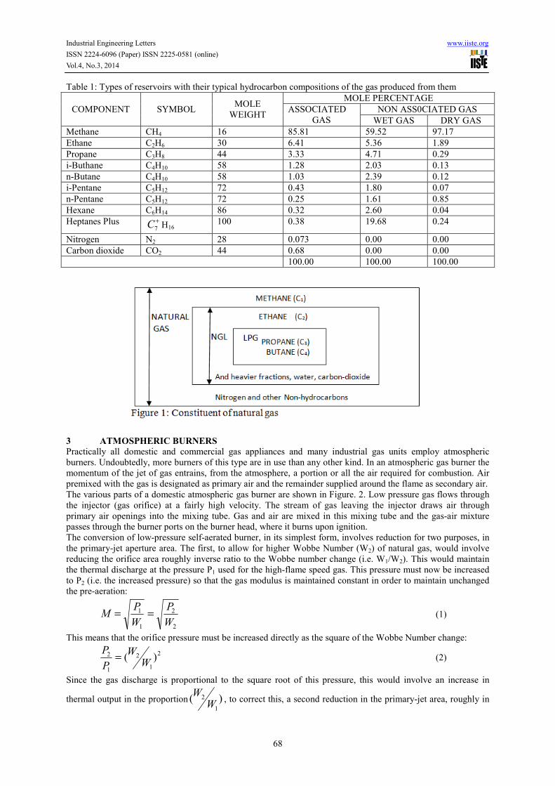
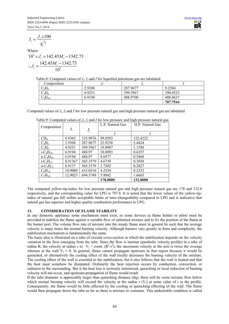
Table.8: Computed values of Ji, Ii and I for liquefied petroleum gas are tabulated:
Composition Ji Ii I C2H6 2.9308 287.9677 9.2384 C3H8 4.9251 399.5967 290.4523 C4H10 6.9194 488.9700 408.0637 707.7544
Computed values of Ji, Ii and I for low pressure natural gas and high pressure natural gas are tabulated Table.9: Computed values of Ji, Ii and I for low pressure and high pressure natural gas
Composition
Ji
iI
L.P. Natural Gas
H.P. Natural Gas
I I CH4 0.9365 125.9876 98.0503 122.4222 C2H6 2.9308 287.9677 22.9238 5.4424 C3H8 4.9251 399.5967 19.8907 1.1588 i-C4H10 6.9194 488.97 10.8093 0.6357 n-C4H10 6.9194 488.97 8.6977 0.5868 i-C5H12 8.91367 565.3579 4.6739 0.3958 n-C5H12 8.9137 565.3579 2.7202 0.2827 C6H14 10.9080 633.0316 4.2534 0.2532 C7H16 12.9023 694.3749 5.9842 1.6665 178.0000 132.8000
The computed yellow-tip-index for low pressure natural gas and high pressure natural gas are 178 and 132.8 respectively, and the corresponding value for LPG is 707.8. It is noted that the lower values of the yellow-tip-index of natural gas fall within acceptable limits of inter-changeability compared to LPG and is indicative that natural gas has superior and higher quality combustion performance to LPG. 13. CONSIDERATION OF FLAME STABILITY
In any domestic appliance some mechanism must exist, or some devices (a flame holder or pilot) must be provided to stabilize the flame against a variable flow of unburned mixture and to fix the position of the flame at the burner port. The volume flow rate of mixture into the steady flame must in general be such that the average velocity is many times the normal burning velocity. Although burners vary greatly in form and complexity, the stabilization mechanism is fundamentally the same. The basic idea is illustrated on a tube of circular cross-section in which the stabilization depends on the velocity variation in the flow emerging from the tube. Since the flow is laminar (parabolic velocity profile) in a tube of radius R; the velocity at radius r is: Vr = const. (R2-r2); the maximum velocity at the axis is twice the average whereas at the wall Vr = 0. In general, flame cannot propagate upstream in that region because it would be quenched, or alternatively the cooling effect of the wall locally decreases the burning velocity of the mixture. The cooling effect of the wall is essential to the stabilization; but it also follows that the wall is heated and that the heat must somehow be dissipated. Ordinarily the heat rejection occurs by conduction, convection, or radiation to the surrounding. But it the heat loss is seriously minimized, quenching or local reduction of burning velocity will not occur, and upstream propagation of flame would result. If the tube diameter is appreciably larger than quenching distance (dq), there will be some mixture flow below which normal burning velocity will exceed the velocity at the radius r (Vr) at some value of r in the profile. Consequently, the flame would be little affected by the cooling or quenching effecting of the wall. The flame would then propagate down the tube as far as there is mixture to consume. This undesirable condition is called

Industrial Engineering Letters www.iiste.org
ISSN 2224-6096 (Paper) ISSN 2225-0581 (online)
Vol.4, No.3, 2014
85
flask-back. There is also some mixture flow above which Vr exceeds the normal burning velocity (Ub) everywhere and the flame lifts from the port and blows off. Stability limits have been extensively studied for a wide variety of mixtures and conditions and shown to be well-correlated in terms of the critical velocity gradient at the tube wall (when it is known from the nature of the flow). For a given primary mixture composition, flash-back (or blow-off) will occur at the same value of boundary or wall velocity gradient in tubes of various sizes, if the corresponding average velocity at flashback (blow-off) is proportional to the tube radius R.
Boundary or wall velocity at flashback is a maximum around 1=φ , as is also wall velocity at blow-off, if the
burner is operated in surrounding inert atmosphere. However, as normally used with air surrounding the burner, the behaviour of rick mixtures is complicated by the entrainment of air at the burner port which sustains combustion of the hot rich products of the primary flame near the port wall. The blow-off velocity is then found
to be increased continuously withφ , or richer mixtures are more stable with respect to blow-off. Together with
the lesser tendency toward flashback in rich mixtures (relative to stoichiometric), it follows that the atmospheric burner has much more latitude for stable operation if the primary mixture in rich. For this reason many appliance burners are routinely adjusted by first making the primary mixture so rich that soot just forms in the burned gas (yellow-tipping), and then increasing the air until the yellow luminosity disappears. The primary equivalence ratio is about 1.5 or more. The Wobbe index of the fuel gas is a commonly used criterion for inter-changeability in adjusting the composition of a substitute fuel. The Wobbe number of propane is W = 38142 x 103 and that for n-butane is W = 61267.2 x 103. Their burning velocities are 45cm/sec. and 43cm/sec for propane and n-butane respectively. These are the main constituents of liquefied petroleum gas. In comparison, the Wobbe Number of methane is 47984.5 x 103 and its burning velocity is 40cm/sec, which is the main constituent of natural gas. It can be seen that the Wobbe Number and the burning velocity of propane, n-butane and methane gas are not too different from each other. Consequently, natural gas would give a stable flame on a burner originally designed for use with LPG. On the other hand, base on the tests carried out with natural gases fed at pressures ranging from 1.227bar to 1.307bar. Shneck and Brunet (1975) (observed that a combustion potential lower than 40.3) (the value for pure methane), which is the limit for blow-off can occur when appreciable amounts of inert such as N2 and C02 are present in the gas. However, the combustion potential can be increased considerably when H2 is present in quantities not exceeding 10% in the gas, without risk of flashback. For the yellow-tip-index, they prescribe that the value of the index should not exceed 230 and preferably remain below 210 for aerated burners. 13. CONCLUSION AND RECOMMENDATION
This study has extensively examined ways to predict the inter-changeability of natural gas with liquefied petroleum gas on domestic burners using their burning characteristics. For the analysis, flame characteristics have been defined in terms of combustion quality, thermal effects and stability parameters. Computed values of the combustion characteristics of LPG are shown side by side with those of low-pressure and high pressure natural gas. It was noted that the values for LPG are higher than the corresponding values for natural gas. In particular, the Wobbe Number for LPG falls outside the range of the general correlation. If the pressure dependence of the heat input is taken into consideration according to equation (6), and in order to achieve the same thermal effects on a given burner, as a condition for inter-changeability of LPG and natural gas, then the supply pressure of the natural gas must be regulated to about twice that to which LPG is normally supplied to the burners. However, the difference in composition between natural gas and LPG and indeed between natural gas from various producer oil fields does not make the substitution a simple process. For instance, irrespective of the composition of the substitute gas, thermal input to the burner should be equivalent. The flame should stay alight on the burner over the usual range of burner turn down, that is to say, the flame should neither flashback lift-off nor blow-off the burners. Dangerous or obnoxious gases should not be formed. Hence, a high quality of combustion determined by a low degree of soot formation and the amount of carbon monoxide produced should be achieved. Therefore, the natural gas should be well treated to enhance its used s domestic fuel. The study reveals that lower aeration factor (high Wobbe Number) would give a lower burning velocity and thus a longer flame. When the inner cone of the flame gets so long that it touches a relatively cold surface such as the bottom of a cooking pan, combustion becomes partially arrested and the carbon monoxide content of the exhaust gases rises sharply. On the other hand, a lower aeration factor also implies that additional (secondary) air is required to fan the flame. For burners installed in confined spaces, it may well be that even the secondary air supply to the flame is restricted and could result in incomplete combustion and thus further increase in carbon monoxide and soot formation. Combustion potential predicts the limit for blow-off that can occur in the gas in the presence of appreciable amounts of inert gases. The study reveals that natural gas is interchangeable with LPG in so far as the combustion potential characteristic is concerned.

Industrial Engineering Letters www.iiste.org
ISSN 2224-6096 (Paper) ISSN 2225-0581 (online)
Vol.4, No.3, 2014
86
Yellow Tip index is the ratio of the primary aeration after substitution to the maximum primary aeration on the yellow tip limit curve of the substitute gas. Since the yellow tip index of natural gas is within the range, the resulting primary aeration with substitution will be above the yellow tip limit curve and yellow tips will not occur with natural gas, thereby fulfilling another condition for inter-changeability. The burning velocity of flame speed is the most important combustion characteristics of the gas. The differences in flame speed occur by virtue of variations in gas composition. Flash back of the flame into the mixing tube of the burner would occur if the flame speed is higher than for which the burner was designed. Whereas, if the flame speed is lower; the flame would lift-off or blow-off the burner. However, gases containing substantial proportions of inert gases such as nitrogen and carbon dioxide have lower burning velocities and could show tendency for unstable flame on converted LPG burner, but burning velocity can be increased considerably when H2 is present is present in quantities not exceeding 10% in the gas without risk of flak back. The foregoing results clearly demonstrate the feasibility of interchanging natural gas with LPG on domestic burners provided the gas is adequately processed and treated for water and hydrocarbon dew points and that the pressure requirements are fulfilled. The inter-changeability does not require any adjustment to the geometry of the burner.
REFERENCES
1. Barber, D. (1980), “Introduction to LPG”. Hazards and Precautions Conference: Fire Protection Association; Conference (5/6 March 1980), London.
2. Chouhury, T. ROY (1973) Applied Engineering Thermodynamics. Tata McGraw-Hill Publishing Company Ltd. New Delhi. Page 159 – 184.
3. De Vries, H., el. at., (2007). Safe operation Of Natural Gas Appliances fuelled With Hydrogen/Natural Gas Mixtures (Progress obtained in Naturalhy-project). Proceedings, International Conference on Hydrogen Safety, San Sebastian, Spain.
4. Delbougg, C. S. (1961) Methods for the determination of Interchangeability of Gases, 8th International Gas Conference, Stochholm
5. Dobelin, E. O. (1966) Measurement Systems International Student Edition: McGraw-Hill. 6. DOE (2007) LNG Interchangeability/Gas Quality: Results of the National Energy Technology Laboratory’s
Research for the FERC on Natural Gas Quality and Interchangeability, DOE/NETL- 207/1290, prepared by U.S. Department of Energy, National Energy Technology Laboratory http://www.fossil.energy.gov/ programs/ oilgas/ publications/lng/lng-interchangeability-rpt.pdf Last accessed 16/10/2012.
7. Douglas, J. F., Gasiorek, J. M. and Swaffield, J. A. (1992) Fluid Mechanics, (Second Edition) Longman Singapore Publishers Singapore.
8. Gas Quality & Interchangeability, Asset Management Services, Issue no.001 15.05.2008 Germanischer Lloyd – Service/Product Description, 20459 Hamburg, Germany http://www.gl- nobledenton.com/assets/downloads/18.Gas_Quality_Interchangeability_external.pdf Last accessed 1/11/2012.
9. Ikoku, Chi U. (1984) Natural Gas Reservoir Engineering John Wiley & Sons Inc. U. S. A. 10. John, E. A. (1965). Commercial Kitchen Gas Appliance, Gas Engineer Handbook (Fuel Gas Engineering
Practice) Industrial Press Inc. New York. Pages: 12/253-12/259. 11. Kentfield, J.A.C. & BARNERS, R. W. (1972) The Prediction of the Optimum Performance of Ejectors.
Heat and Fluid Flow Journal, Vol. 2 No. 2 12. Knapp K. R., John, E. A. and Kafka, Evelyn M., (1965), Domestic Gas Cooking Appliances: Gas Engineer
Handbook (Fuel Gas Engineering Practice), Industrial Press Inc. New York. Page 12/152- 12/157 13. Kristensen, P. G., (2007). “Formaldehyde Reduction by Catalyst, Full-Scale Testing on Gas Engines,”
Project Report, PSO project 5230, February 2007. 14. Levinsky, H. B. (2008). Consumer Appliance Population Raises Issues In Gas Interchangeability Testing.
Pipeline & Gas Journal, January: 66-70 15. Linden, Henry. R. and Himmelblau, D. M. (1978), “Burner Technology” Encyclopedia of Chemical
Technology, Third Edition (Vol. 4): John Wiley & Sons. New York. page, 278 – 307. 16. Loubar K., Rahmouni C., Le Corre O. and Tazerout M. (2007). A combustionless determination method for
combustion properties of natural gases, Fuel, Vol. 86, No.16, p 2535-2544, ISSN 0016- 2361, DOI: 10.1016/j.fuel.2007.02.024.
17. Maleev, V. L. (1972) Internal Combustion Engines, International Students Edition McGraw-Hill 18. Mike Segers, P.E., el.ta. (2011).“Blending Fuel Gas to Optimize use of Off-Spec Natural Gas” Presented at
ISA Power Industry Division 54th Annual I&C Symposium; http://www.isa.org; http://cosaxentaur.com/resources/article_level2a/533/Fuel-Gas-Blending-Paper.pdf., Last Accessed 16 October 2012
19. Monroe E. S.; Jr. (1967) “ Heat Generation” in Section 9 of Chemical Engineers Handbook, 5th Edition (H.

Industrial Engineering Letters www.iiste.org
ISSN 2224-6096 (Paper) ISSN 2225-0581 (online)
Vol.4, No.3, 2014
87
H. Perry ad C. H. Chiton, Editors) McGraw-Hill, New York. Van Nostia Scientific Encyclopedia, fifth Edition, U. S. A. (1976). Page: 624.
20. “New Pipeline Transports Yates Gas to Odessa Power Plants”, Permian Basin Petroleum Association Magazine, Issue No. 33, December 2010.
21. Olivier Le Corre and Khaled Loubar (2010). Natural Gas : Physical Properties and Combustion Features,Natural Gas, Primož PotoĠnik (Ed.), ISBN: 978-953-307-112-1, InTech, http://cdn.intechopen.com/pdfs/11458/InTechNatural_gas_physical_properties_and_combustion_features.pdf last accessed 1/11/2012.
22. Peter A DeBarber, HORIBA Instruments and Donna L Dearmon, Kurz Technical Systems, “A Novel
Instrument for In-Situ NOx
Measurement Applied to SCR Units”, 18th
Annual Joint ISA POWID/EPRI
Controls and Instrumentation Conference and 51st
ISA POWID Symposia, 2008, Scottsdale, Arizona. 23. Rosenhead, L. (1963) Laminar Boundary Layers, Clarendon Press, Oxford. 24. Saikaly K., Rousseau S., Rahmouni C., Le Corre O. & Truffet L. (2008). Safe operating conditions
determination for stationary SI gas engines, Fuel Processing Technology,Vol. 89, No. 11, 1p169-1179, ISSN 0378-3820
25. Schneck, V & Brunet, K. (1975) Interchangeability: A Gas Quality Problem, Quality Problem, National Gas Conference Paper No.2, Folkestone
26. The Badcock and Willox Company (1976), “Steam–its Generation and Use”, 38th Edition, New York Van Nostia Scientific Encyclopedia, Fifth Edition, U.S.A. Page 619-640
27. “The Wobbe Index and Natural Gas Interchangeability”, Emerson Process Management Application Data Document 1660AD-5a, 2007.
28. Thomas, T. H. AND Hunt, R. (1971) Applied Heat Heinemann Educational Book Limited London. 29. Van Essen, V.M., el.ta. (2011). Possibilities for Admixing Gasification Gases: Combustion Aspects in
Domestic Natural Gas Appliances in the Netherlands International Gas Union Research Conference 2011 30. Weber, E. J. and Vandaveer, F. E. (1965), “Gas Burner Design”, Gas Engineer Handbook, (Fuel Gas
Engineering practice), Industrial Press Inc, New York. Page12/193-12/209 31. Weber, E. J., (1965). Interchangeability of Fuel Gases: Gas Engineer Hand Book (Fuel Gas Engineering
Practice) Industrial Press Inc. New York page 12/239-12/247.