Embed Size (px)
Citation preview
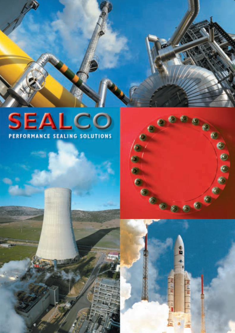
THE COMPANY
The Company . . . . . . . . . . . . . . . . . . . . . . 3
The Products . . . . . . . . . . . . . . . . . . . . . . 3
Typical Applications . . . . . . . . . . . . . . . . . 3
INTRODUCTION
Quality, Expertise and Flexibility . . . . . . . . 4
How does a High Tech Metal Seal work . . 5
Terminology . . . . . . . . . . . . . . . . . . . . . . . . 5
SEAL TYPES
C-Seals . . . . . . . . . . . . . . . . . . . . . . . . . . . 6
O-Seals . . . . . . . . . . . . . . . . . . . . . . . . . . . 7
HOW TO ORDER
The part number system . . . . . . . . . . . . . 8
SEAL DATA SHEETS
OI-Seals . . . . . . . . . . . . . . . . . . . . . . . . . 12
OE-Seals . . . . . . . . . . . . . . . . . . . . . . . . . 13
CI-Seals . . . . . . . . . . . . . . . . . . . . . . . . . 14
CE-Seals . . . . . . . . . . . . . . . . . . . . . . . . . 15
CSI-Seals . . . . . . . . . . . . . . . . . . . . . . . . 16
CSE-Seals . . . . . . . . . . . . . . . . . . . . . . . . 17
CA-Seals . . . . . . . . . . . . . . . . . . . . . . . . . 18
WI-Seals . . . . . . . . . . . . . . . . . . . . . . . . . 20
WE-Seals . . . . . . . . . . . . . . . . . . . . . . . . 21
Shaped Seals & specials . . . . . . . . . . . . . . 22
Tolerances . . . . . . . . . . . . . . . . . . . . . . . 23
Conversion table . . . . . . . . . . . . . . . . . . 24
OTHER SEALCO PRODUCTS
PTFE-seals . . . . . . . . . . . . . . . . . . . . . . . 25
O Rings and Cord . . . . . . . . . . . . . . . . . 26
Back-up Rings . . . . . . . . . . . . . . . . . . . . . 26
Rotary Shaft Seals . . . . . . . . . . . . . . . . . . 26
Shaft Repair Kits . . . . . . . . . . . . . . . . . . . 26
Front seals . . . . . . . . . . . . . . . . . . . . . . . 27
Gland / Piston Seals . . . . . . . . . . . . . . . . 27
Wiper / Scraper Seals . . . . . . . . . . . . . . . 27
3
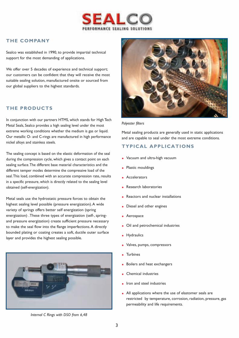
Metal sealing products are generally used in static applicationsand are capable to seal under the most extreme conditions.
TYPICAL APPLICATIONS
• Vacuum and ultra-high vacuum
• Plastic mouldings
• Accelerators
• Research laboratories
• Reactors and nuclear installations
• Diesel and other engines
• Aerospace
• Oil and petrochemical industries
• Hydraulics
• Valves, pumps, compressors
• Turbines
• Boilers and heat exchangers
• Chemical industries
• Iron and steel industries
• All applications where the use of elastomer seals are restricted by temperature, corrosion, radiation, pressure, gas permeability and life requirements.
THE PRODUCTS
In conjunction with our partners HTMS, which stands for High TechMetal Seals, Sealco provides a high sealing level under the mostextreme working conditions whether the medium is gas or liquid.Our metallic O- and C-rings are manufactured in high performancenickel alloys and stainless steels.
The sealing concept is based on the elastic deformation of the sealduring the compression cycle, which gives a contact point on eachsealing surface.The different base material characteristics and thedifferent temper modes determine the compressive load of theseal.This load, combined with an accurate compression rate, resultsin a specific pressure, which is directly related to the sealing levelobtained (self-energization).
Metal seals use the hydrostatic pressure forces to obtain thehighest sealing level possible (pressure energization).A widevariety of springs offers better self energization (springenergization) .These three types of energization (self-, spring-and pressure energization) create sufficient pressure necessaryto make the seal flow into the flange imperfections.A directlybounded plating or coating creates a soft, ductile outer surfacelayer and provides the highest sealing possible.
THE COMPANY
Sealco was established in 1990, to provide impartial technicalsupport for the most demanding of applications.
We offer over 5 decades of experience and technical support;our customers can be confident that they will receive the mostsuitable sealing solution, manufactured onsite or sourced fromour global suppliers to the highest standards.
Internal C Rings with DSO from 6,48
Polyester filters
4
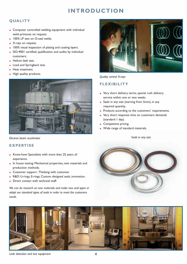
INTRODUCTION
QUALITY
• Computer controlled welding equipment with individual weld printouts on request.
• 100% LP test on O-seal welds.
• X-rays on request.
• 100% visual inspection of plating and coating layers.
• ISO-9001 certified, qualification and audits by individual customers.
• Helium leak test.
• Load and Springback test.
• Heat treatment.
• High quality products.
EXPERTISE
• Know-how: Specialists with more than 25 years of experience.
• In house testing: Mechanical properties, new materials and production methods.
• Customer support :Thinking with customer.
• R&D: U-rings, E-rings, Custom designed seals, innovation.
• Direct contact with technical staff.
We can do research on new materials and make new seal types oradapt our standard types of seals in order to meet the customersneeds.
Electron beam accelerator
Quality control X-rays
Seals in any size
Leak detection and test equipment
FLEXIBILITY
• Very short delivery terms, special rush delivery service within one or two weeks
• Seals in any size (starting from 5mm), in any required quantity.
• Products according to the customers’ requirements.
• Very short response time on customers demands (standard 1 day).
• Competitive pricing.
• Wide range of standard materials.
5
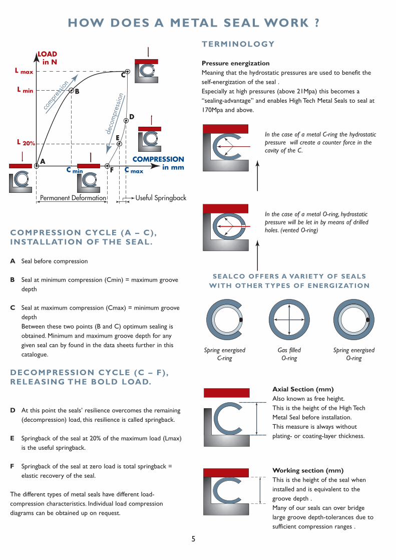
HOW DOES A METAL SEAL WORK ?
COMPRESSION CYCLE (A – C),INSTALLATION OF THE SEAL.
A Seal before compression
B Seal at minimum compression (Cmin) = maximum groove depth
C Seal at maximum compression (Cmax) = minimum groove depth Between these two points (B and C) optimum sealing is obtained. Minimum and maximum groove depth for any given seal can by found in the data sheets further in this catalogue.
DECOMPRESSION CYCLE (C – F) ,RELEASING THE BOLD LOAD.
D At this point the seals’ resilience overcomes the remaining (decompression) load, this resilience is called springback.
E Springback of the seal at 20% of the maximum load (Lmax) is the useful springback.
F Springback of the seal at zero load is total springback = elastic recovery of the seal.
The different types of metal seals have different load-compression characteristics. Individual load compressiondiagrams can be obtained up on request.
TERMINOLOGY
Pressure energizationMeaning that the hydrostatic pressures are used to benefit theself-energization of the seal .Especially at high pressures (above 21Mpa) this becomes a“sealing-advantage” and enables High Tech Metal Seals to seal at170Mpa and above.
In the case of a metal C-ring the hydrostaticpressure will create a counter force in thecavity of the C.
In the case of a metal O-ring, hydrostaticpressure will be let in by means of drilledholes. (vented O-ring)
Working section (mm)This is the height of the seal wheninstalled and is equivalent to thegroove depth .Many of our seals can over bridgelarge groove depth-tolerances due tosufficient compression ranges .
Axial Section (mm)Also known as free height.This is the height of the High TechMetal Seal before installation.This measure is always withoutplating- or coating-layer thickness.
Spring energised C-ring
Gas filledO-ring
Spring energised O-ring
SEALCO OFFERS A VARIETY OF SEALSWITH OTHER TYPES OF ENERGIZATION
6
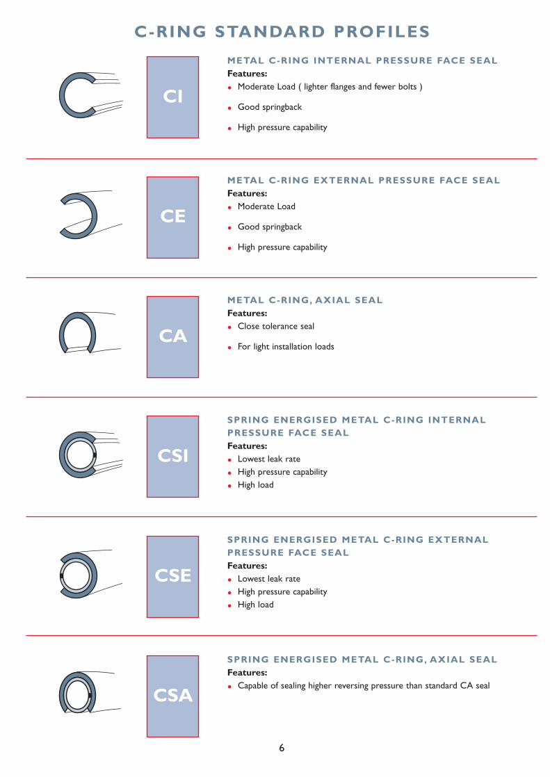
C-RING STANDARD PROFILES
CI
METAL C-RING INTERNAL PRESSURE FACE SEALFeatures:
• Moderate Load ( lighter flanges and fewer bolts )
• Good springback
• High pressure capability
CE
METAL C-RING EXTERNAL PRESSURE FACE SEALFeatures:
• Moderate Load
• Good springback
• High pressure capability
CA
METAL C-RING, AXIAL SEALFeatures:
• Close tolerance seal
• For light installation loads
CSI
SPRING ENERGISED METAL C-RING INTERNALPRESSURE FACE SEALFeatures:
• Lowest leak rate
• High pressure capability
• High load
CSE
SPRING ENERGISED METAL C-RING EXTERNALPRESSURE FACE SEALFeatures:
• Lowest leak rate
• High pressure capability
• High load
CSA
SPRING ENERGISED METAL C-RING, AXIAL SEALFeatures:
• Capable of sealing higher reversing pressure than standard CA seal
7
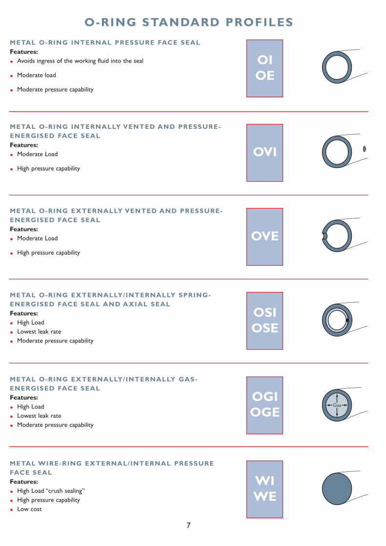
O-RING STANDARD PROFILES
OIOE
METAL O-RING INTERNAL PRESSURE FACE SEALFeatures:
• Avoids ingress of the working fluid into the seal
• Moderate load
• Moderate pressure capability
OVI
METAL O-RING INTERNALLY VENTED AND PRESSURE-ENERGISED FACE SEALFeatures:
• Moderate Load
• High pressure capability
OVE
METAL O-RING EXTERNALLY VENTED AND PRESSURE-ENERGISED FACE SEALFeatures:
• Moderate Load
• High pressure capability
OSIOSE
METAL O-RING EXTERNALLY/INTERNALLY SPRING-ENERGISED FACE SEAL AND AXIAL SEALFeatures:
• High Load
• Lowest leak rate
• Moderate pressure capability
OGIOGE
METAL O-RING EXTERNALLY/INTERNALLY GAS-ENERGISED FACE SEALFeatures:
• High Load
• Lowest leak rate
• Moderate pressure capability
WIWE
METAL WIRE-RING EXTERNAL/INTERNAL PRESSUREFACE SEALFeatures:
• High Load “crush sealing”
• High pressure capability
• Low cost
8
HOW TO ORDER
C S I - 0 0 8 0 0 0 - 2 , 3 9 M - 1 / 1 - 1 - S 3 0
THE PART NUMBER SYSTEM
The first section of the part number refers to the TYPE OF SEAL you want to select:
CI Metal C-ring, internal pressure face seal
CE Metal C-ring, external pressure face seal
CSI Metal C-ring, spring energized, internal pressure face seal
CSE Metal C-ring, spring energized, external pressure face seal
CA Metal C-ring, axial seal
CSA Metal C-ring, spring energized axial seal
OI Metal O-ring, internal pressure face seal
OE Metal O-ring, external pressure face seal
OVI Metal O-ring, internal vented and pressure energized face seal
OVE Metal O-ring, external vented and pressure energized face seal
OGI Metal O-ring, pressure filled, internal pressure face seal
OGE Metal O-ring, pressure filled, external pressure face seal
OSI Metal O-ring, spring energized, internal pressure face and axial seal
OSE Metal O-ring, spring energized, external pressure face and axial sea
WI Metal Wire-ring, internal pressure face seal
WE Metal Wire-ring, external pressure face seal
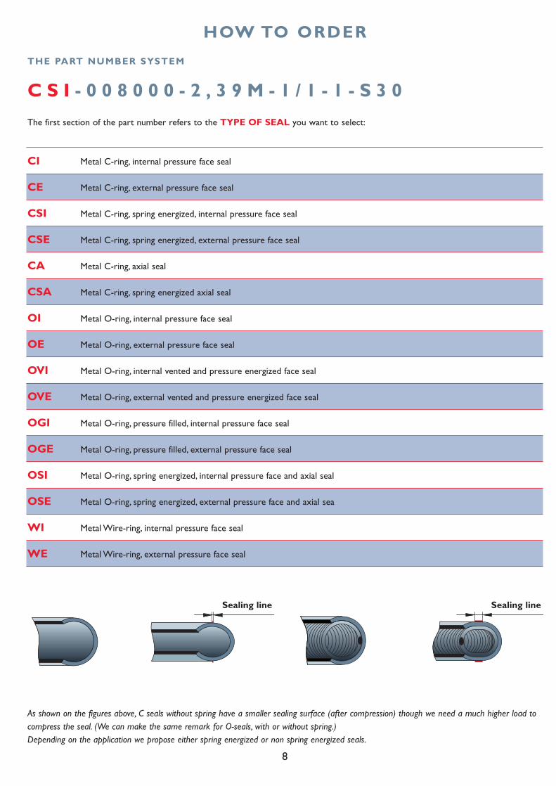
As shown on the figures above, C seals without spring have a smaller sealing surface (after compression) though we need a much higher load tocompress the seal. (We can make the same remark for O-seals, with or without spring.)Depending on the application we propose either spring energized or non spring energized seals.
Sealing line Sealing line
9
C S I - 0 0 8 0 0 0 - 2 , 3 9 M - 1 / 1 - 1 - S 3 0
C S I - 0 0 8 0 0 0 - 2 , 3 9 M - 1 / 1 - 1 - S 3 0
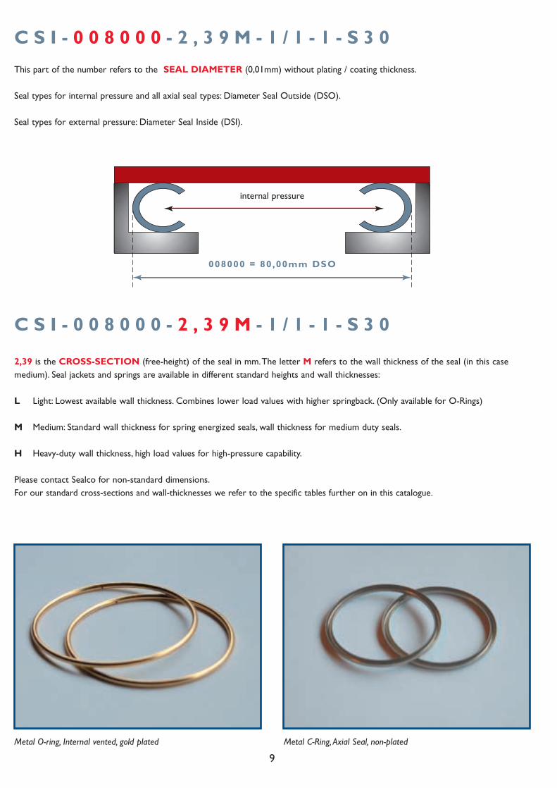
This part of the number refers to the SEAL DIAMETER (0,01mm) without plating / coating thickness.
Seal types for internal pressure and all axial seal types: Diameter Seal Outside (DSO).
Seal types for external pressure: Diameter Seal Inside (DSI).
008000 = 80,00mm DSO
internal pressure
2,39 is the CROSS-SECTION (free-height) of the seal in mm.The letter M refers to the wall thickness of the seal (in this casemedium). Seal jackets and springs are available in different standard heights and wall thicknesses:
L Light: Lowest available wall thickness. Combines lower load values with higher springback. (Only available for O-Rings)
M Medium: Standard wall thickness for spring energized seals, wall thickness for medium duty seals.
H Heavy-duty wall thickness, high load values for high-pressure capability.
Please contact Sealco for non-standard dimensions.For our standard cross-sections and wall-thicknesses we refer to the specific tables further on in this catalogue.
Metal C-Ring, Axial Seal, non-platedMetal O-ring, Internal vented, gold plated
10
C S I - 0 0 8 0 0 0 - 2 , 3 9 M - 1 / 1 - 1 - S 3 0
C S I - 0 0 8 0 0 0 - 2 , 3 9 M - 1 / 1 - 1 - S 3 0
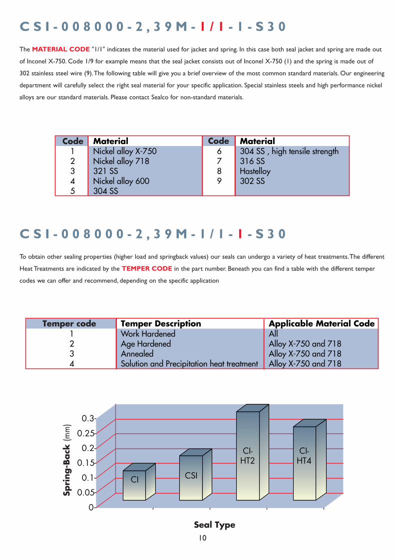
The MATERIAL CODE "1/1" indicates the material used for jacket and spring. In this case both seal jacket and spring are made out
of Inconel X-750. Code 1/9 for example means that the seal jacket consists out of Inconel X-750 (1) and the spring is made out of
302 stainless steel wire (9).The following table will give you a brief overview of the most common standard materials. Our engineering
department will carefully select the right seal material for your specific application. Special stainless steels and high performance nickel
alloys are our standard materials. Please contact Sealco for non-standard materials.
To obtain other sealing properties (higher load and springback values) our seals can undergo a variety of heat treatments.The different
Heat Treatments are indicated by the TEMPER CODE in the part number. Beneath you can find a table with the different temper
codes we can offer and recommend, depending on the specific application
Temper code Temper Description Applicable Material Code Work Hardened All
21
Age Hardened Alloy X-750 and 7183 Annealed Alloy X-750 and 7184 Solution and Precipitation heat treatment Alloy X-750 and 718
0
0.05
0.1
0.15
0.2
0.25
0.3
Spri
ng-B
ack
(mm
)
Seal Type
CI CSI
CI-HT2
CI-HT4
11
C S I - 0 0 8 0 0 0 - 2 , 3 9 M - 1 / 1 - 1 - S 3 0
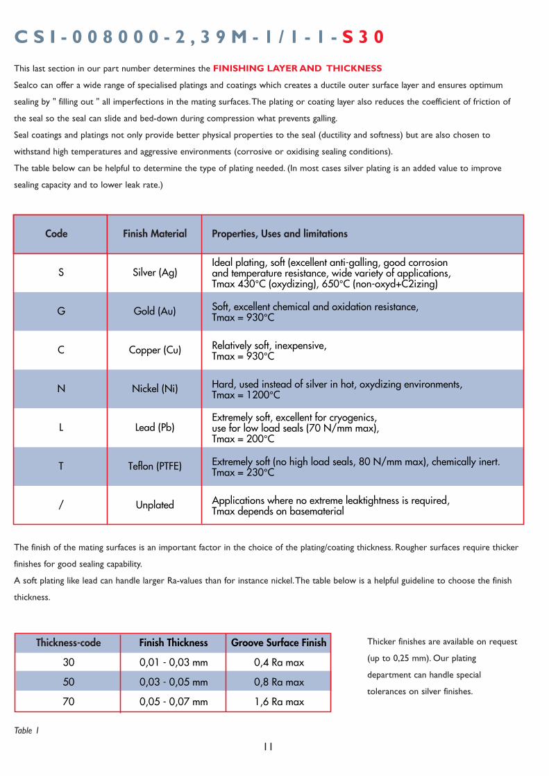
This last section in our part number determines the FINISHING LAYER AND THICKNESS
Sealco can offer a wide range of specialised platings and coatings which creates a ductile outer surface layer and ensures optimum
sealing by " filling out " all imperfections in the mating surfaces.The plating or coating layer also reduces the coefficient of friction of
the seal so the seal can slide and bed-down during compression what prevents galling.
Seal coatings and platings not only provide better physical properties to the seal (ductility and softness) but are also chosen to
withstand high temperatures and aggressive environments (corrosive or oxidising sealing conditions).
The table below can be helpful to determine the type of plating needed. (In most cases silver plating is an added value to improve
sealing capacity and to lower leak rate.)
Code Finish Material Properties, Uses and limitations
S Silver (Ag)Ideal plating, soft (excellent anti-galling, good corrosion and temperature resistance, wide variety of applications, Tmax 430°C (oxydizing), 650°C (non-oxyd+C2izing)
G Gold (Au) Soft, excellent chemical and oxidation resistance, Tmax = 930°C
C Copper (Cu) Relatively soft, inexpensive, Tmax = 930°C
N Nickel (Ni) Hard, used instead of silver in hot, oxydizing environments, Tmax = 1200°C
L Lead (Pb)Extremely soft, excellent for cryogenics, use for low load seals (70 N/mm max), Tmax = 200°C
T Teflon (PTFE) Extremely soft (no high load seals, 80 N/mm max), chemically inert. Tmax = 230°C
/ Unplated Applications where no extreme leaktightness is required, Tmax depends on basematerial
The finish of the mating surfaces is an important factor in the choice of the plating/coating thickness. Rougher surfaces require thicker
finishes for good sealing capability.
A soft plating like lead can handle larger Ra-values than for instance nickel.The table below is a helpful guideline to choose the finish
thickness.
Thickness-code Finish Thickness Groove Surface Finish
30 0,01 - 0,03 mm 0,4 Ra max
50 0,03 - 0,05 mm 0,8 Ra max
70 0,05 - 0,07 mm 1,6 Ra max
Thicker finishes are available on request
(up to 0,25 mm). Our plating
department can handle special
tolerances on silver finishes.
Table 1
12
O I - D A T A S H E E T
AS MT DC DG GD WG R
Axial Section Tolerance on AS Material Code Material
ThicknessDiametrical Clearance
Diameter Groove (range)
Groove Depth (min/max)
Widht Groove (minimum)
Radius (maximum)
0,89 +0,08/-0,03 M 0,15 0,2 6,35-25 0,64-0,69 1,4 0,25
1,19 +0,08/-0,03 H 0,20 0,25 10,00-50 0,94-1,02 1,78 0,3
L 0,15M 0,25H 0,36
L 0,15M 0,25H 0,46
1,57
2,39
Groove DimensionsSeal dimensions
13-200 3,181,88-2,01 0,51
0,382,29
9,53
0,28
0,33
0,71
0,76
1,02
4,78
6,35
0,433,18
3,96 0,61
M H
M H
0,25 0,51
0,41 0,51
4,06 0,76
75-650 3,18-3,30 5,08 1,27
1,14-1,2710-200
8,26-8,51300-2000
25-400 2,54-2,67
1,5212,7
200-1200 5,05-5,28 8,89 1,52
6,353,84-3,99100-800 1,27
+0,08/-0,03
+0,08/-0,03
+0,08/-0,03
+0,10
+0,13
+0,13
+0,13
M H
M H
M H
0,51 0,64
0,64 0,81
0,97 1,24
12,70 1,27 800-3000 11,05-11,43 16,51 1,52+0,15 M H
1,27 1,65
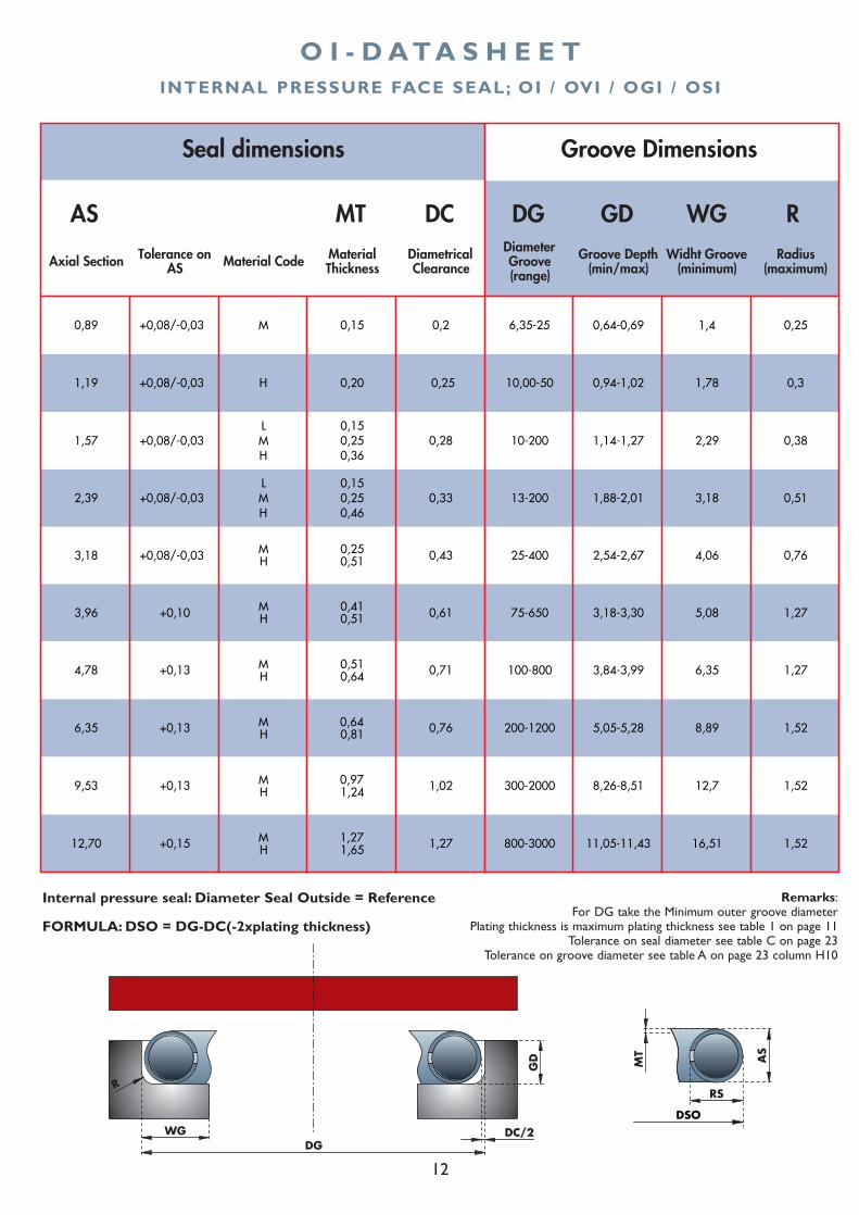
INTERNAL PRESSURE FACE SEAL; OI / OVI / OGI / OSI
AS
MT
DGWG
R
GD
DC/2
RS
DSO
Internal pressure seal: Diameter Seal Outside = Reference Remarks:For DG take the Minimum outer groove diameter
Plating thickness is maximum plating thickness see table 1 on page 11Tolerance on seal diameter see table C on page 23
Tolerance on groove diameter see table A on page 23 column H10
FORMULA: DSO = DG-DC(-2xplating thickness)
13
O E - D A T A S H E E T
AS MT DC DG GD WG R
Axial Section Tolerance on AS Material Code Material
ThicknessDiametrical Clearance
Diameter Groove (range)
Groove Depth (min/max)
Widht Groove (minimum)
Radius (maximum)
0,89 +0,08/-0,03 M 0,15 0,2 6,35-25 0,64-0,69 1,4 0,25
1,19 +0,08/-0,03 H 0,20 0,25 10,00-50 0,94-1,02 1,78 0,3
L 0,15M 0,25H 0,36
L 0,15M 0,25H 0,46
1,57
2,39
Groove DimensionsSeal dimensions
13-200 3,181,88-2,01 0,51
0,382,29
9,53
0,28
0,33
0,71
0,76
1,02
4,78
6,35
0,433,18
3,96 0,61
M H
M H
0,25 0,51
0,41 0,51
4,06 0,76
75-650 3,18-3,30 5,08 1,27
1,14-1,2710-200
8,26-8,51300-2000
25-400 2,54-2,67
1,5212,7
200-1200 5,05-5,28 8,89 1,52
6,353,84-3,99100-800 1,27
+0,08/-0,03
+0,08/-0,03
+0,08/-0,03
+0,10
+0,13
+0,13
+0,13
M H
M H
M H
0,51 0,64
0,64 0,81
0,97 1,24
12,70 1,27 800-3000 11,05-11,43 16,51 1,52+0,15 M H
1,27 1,65
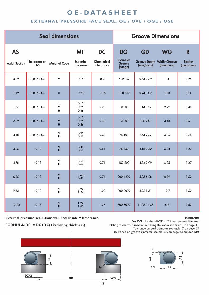
EXTERNAL PRESSURE FACE SEAL; OE / OVE / OGE / OSE
AS
MT
RSDSI
DC/2
GD
R
DG WG
External pressure seal: Diameter Seal Inside = Reference
FORMULA: DSI = DG+DC(+2xplating thickness)
Remarks:For DG take the MAXIMUM inner groove diameter
Plating thickness is maximum plating thickness see table 1 on page 11Tolerance on seal diameter see table C on page 23
Tolerance on groove diameter see table A on page 23 column h10
14
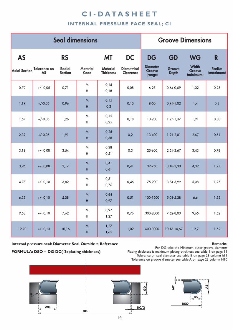
C I - D A T A S H E E T
AS RS MT DC DG GD WG R
Axial Section Tolerance on AS
Radial Section
Material Code
Material Thickness
Diametrical Clearence
Diameter Groove (range)
Groove Depth
Width Groove
(minimum)
Radius (maximum)
M 0,15
H 0,18
M 0,15
H 0,2
M 0,15
H 0,25
M 0,25
H 0,38
M 0,38
H 0,51
M 0,41
H 0,61
M 0,51
H 0,76
M 0,64
H 0,97
M 0,97
H 1,27
M 1,27
H 1,65
+/- 0,10
+/- 0,13
0,76
1,02
+/- 0,05
+/-0,05
+/-0,05
+/-0,05
+/- 0,08
+/- 0,08
+/- 0,10
+/- 0,10
0,3
0,41
0,46
0,51
1,57
1,19
2,39
3,18
3,96
4,78
6,35
9,53
12,70
0,79 0,71
0,96
10,16
7,62
5,08
3,82
3,17
2,54
1,91
1,26
6-25
8-50
10-200
13-400
0,08
0,15
0,18
0,2
25-600
32-750
75-900
100-1200
300-2000
600-3000 10,16-10,67
7,62-8,03
5,08-5,28
3,84-3,99
3,18-3,30
2,54-2,67
0,64-0,69
1,4
1,91
2,67
3,43
4,32
5,08
6,6
9,65
12,7 1,52
1,52
1,52
1,27
1,27
0,76
Seal dimensions Groove Dimensions
0,51
0,38
0,3
0.25
1,91-2,01
1,27-1,37
0,94-1,02
1,02
INTERNAL PRESSURE FACE SEAL; CI
Internal pressure seal: Diameter Seal Outside = Reference
FORMULA: DSO = DG-DC(-2xplating thickness)
AS
MT
DGWG
R
GD
DC/2
RS
DSO
Remarks:For DG take the Minimum outer groove diameter
Plating thickness is maximum plating thickness see table 1 on page 11Tolerance on seal diameter see table B on page 23 column h11
Tolerance on groove diameter see table A on page 23 column H10
15
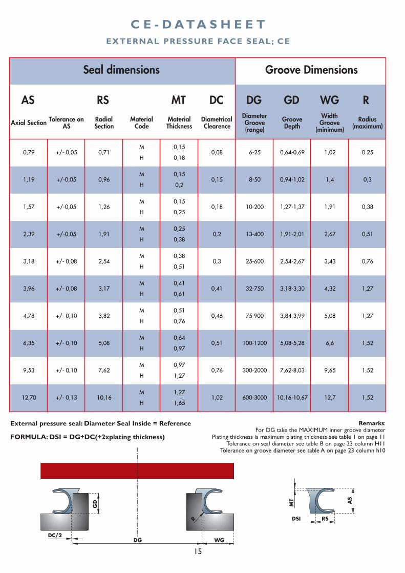
C E - D A T A S H E E T
AS RS MT DC DG GD WG R
Axial Section Tolerance on AS
Radial Section
Material Code
Material Thickness
Diametrical Clearence
Diameter Groove (range)
Groove Depth
Width Groove
(minimum)
Radius (maximum)
M 0,15
H 0,18
M 0,15
H 0,2
M 0,15
H 0,25
M 0,25
H 0,38
M 0,38
H 0,51
M 0,41
H 0,61
M 0,51
H 0,76
M 0,64
H 0,97
M 0,97
H 1,27
M 1,27
H 1,65
+/- 0,10
+/- 0,13
0,76
1,02
+/- 0,05
+/-0,05
+/-0,05
+/-0,05
+/- 0,08
+/- 0,08
+/- 0,10
+/- 0,10
0,3
0,41
0,46
0,51
1,57
1,19
2,39
3,18
3,96
4,78
6,35
9,53
12,70
0,79 0,71
0,96
10,16
7,62
5,08
3,82
3,17
2,54
1,91
1,26
6-25
8-50
10-200
13-400
0,08
0,15
0,18
0,2
25-600
32-750
75-900
100-1200
300-2000
600-3000 10,16-10,67
7,62-8,03
5,08-5,28
3,84-3,99
3,18-3,30
2,54-2,67
0,64-0,69
1,4
1,91
2,67
3,43
4,32
5,08
6,6
9,65
12,7 1,52
1,52
1,52
1,27
1,27
0,76
Seal dimensions Groove Dimensions
0,51
0,38
0,3
0.25
1,91-2,01
1,27-1,37
0,94-1,02
1,02
EXTERNAL PRESSURE FACE SEAL; CE
External pressure seal: Diameter Seal Inside = Reference
FORMULA: DSI = DG+DC(+2xplating thickness)
AS
MT
RSDSI
DC/2
GD
R
DG WG
Remarks:For DG take the MAXIMUM inner groove diameter
Plating thickness is maximum plating thickness see table 1 on page 11Tolerance on seal diameter see table B on page 23 column H11
Tolerance on groove diameter see table A on page 23 column h10
16
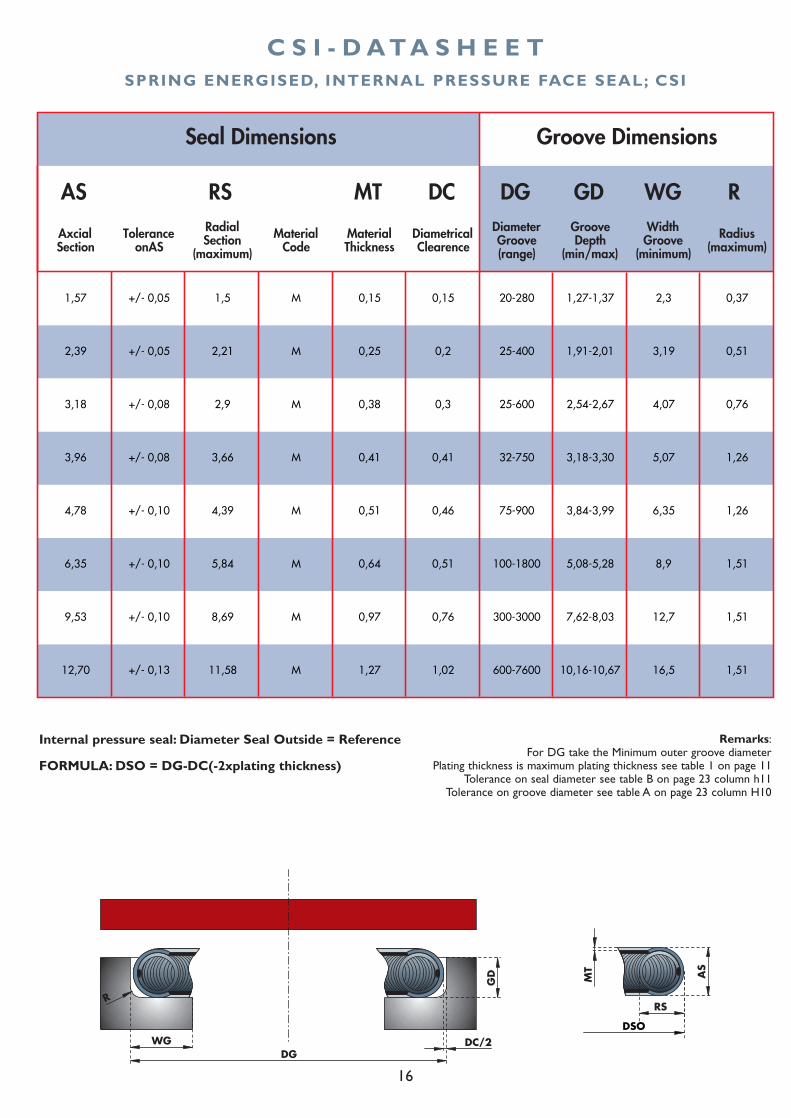
C S I - D A T A S H E E T
AS RS MT DC DG GD WG R
Axcial Section
Tolerance onAS
Radial Section
(maximum)
Material Code
Material Thickness
Diametrical Clearence
Diameter Groove (range)
Groove Depth
(min/max)
Width Groove
(minimum)
Radius (maximum)
1,57 +/- 0,05 1,5 M 0,15 0,15 20-280 1,27-1,37 2,3 0,37
2,39 +/- 0,05 2,21 M 0,25 0,2 25-400 1,91-2,01 3,19 0,51
3,18 +/- 0,08 2,9 M 0,38 0,3 25-600 2,54-2,67 4,07 0,76
3,96 +/- 0,08 3,66 M 0,41 0,41 32-750 3,18-3,30 5,07 1,26
4,78 +/- 0,10 4,39 M 0,51 0,46 75-900 3,84-3,99 6,35 1,26
6,35 +/- 0,10 5,84 M 0,64 0,51 100-1800 5,08-5,28 8,9 1,51
9,53 +/- 0,10 8,69 M 0,97 0,76 300-3000 7,62-8,03 12,7 1,51
12,70 +/- 0,13 11,58 M 1,27 1,02 600-7600 10,16-10,67 16,5 1,51
Seal Dimensions Groove Dimensions
SPRING ENERGISED, INTERNAL PRESSURE FACE SEAL; CSI
Internal pressure seal: Diameter Seal Outside = Reference
FORMULA: DSO = DG-DC(-2xplating thickness)
AS
MT
DGWG
R
GD
DC/2
RS
DSO
Remarks:For DG take the Minimum outer groove diameter
Plating thickness is maximum plating thickness see table 1 on page 11Tolerance on seal diameter see table B on page 23 column h11
Tolerance on groove diameter see table A on page 23 column H10
17
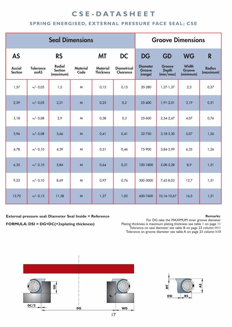
C S E - D A T A S H E E T
AS RS MT DC DG GD WG R
Axcial Section
Tolerance onAS
Radial Section
(maximum)
Material Code
Material Thickness
Diametrical Clearence
Diameter Groove (range)
Groove Depth
(min/max)
Width Groove
(minimum)
Radius (maximum)
1,57 +/- 0,05 1,5 M 0,15 0,15 20-280 1,27-1,37 2,3 0,37
2,39 +/- 0,05 2,21 M 0,25 0,2 25-400 1,91-2,01 3,19 0,51
3,18 +/- 0,08 2,9 M 0,38 0,3 25-600 2,54-2,67 4,07 0,76
3,96 +/- 0,08 3,66 M 0,41 0,41 32-750 3,18-3,30 5,07 1,26
4,78 +/- 0,10 4,39 M 0,51 0,46 75-900 3,84-3,99 6,35 1,26
6,35 +/- 0,10 5,84 M 0,64 0,51 100-1800 5,08-5,28 8,9 1,51
9,53 +/- 0,10 8,69 M 0,97 0,76 300-3000 7,62-8,03 12,7 1,51
12,70 +/- 0,13 11,58 M 1,27 1,02 600-7600 10,16-10,67 16,5 1,51
Seal Dimensions Groove Dimensions
SPRING ENERGISED, EXTERNAL PRESSURE FACE SEAL; CSE
External pressure seal: Diameter Seal Inside = Reference
FORMULA: DSI = DG+DC(+2xplating thickness)
AS
MT
RSDSI
DC/2
GD
R
DG WG
Remarks:For DG take the MAXIMUM inner groove diameter
Plating thickness is maximum plating thickness see table 1 on page 11Tolerance on seal diameter see table B on page 23 column H11
Tolerance on groove diameter see table A on page 23 column h10
18
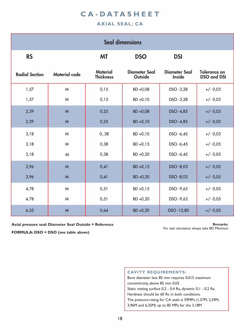
C A - D A T A S H E E T
RS MT DSO DSI
Radial Section Material code Material Thickness
Diameter Seal Outside
Diameter Seal Inside
Tolerance on DSO and DSI
1,57 M 0,15 BD +0,08 DSO -3,28 +/- 0,03
1,57 M 0,15 BD +0,10 DSO -3,28 +/- 0,03
2,39 M 0,25 BD +0,08 DSO -4,85 +/- 0,03
2,39 M 0,25 BD +0,10 DSO -4,85 +/- 0,03
3,18 M 0,.38 BD +0,10 DSO -6,45 +/- 0,03
3,18 M 0,38 BD +0,15 DSO -6,45 +/- 0,05
3,18 M 0,38 BD +0,20 DSO -6,45 +/- 0,05
3,96 M 0,41 BD +0,15 DSO -8,03 +/- 0,05
3,96 M 0,41 BD +0,20 DSO -8,03 +/- 0,05
4,78 M 0,51 BD +0,15 DSO -9,63 +/- 0,05
4,78 M 0,51 BD +0,20 DSO -9,63 +/- 0,05
6,35 M 0,64 BD +0,20 DSO -12,80 +/- 0,05
Seal dimensions
AXIAL SEAL; CA
Axial pressure seal: Diameter Seal Outside = Reference
FORMULA: DSO = DSO (see table above)
Remarks:For seal calculation always take BD Minimum
CAVITY REQUIREMENTS:Bore diameter less 85 mm requires 0,015 maximumconcentricity, above 85 mm 0,03.Static mating surface 0,2 - 0,4 Ra, dynamic 0,1 - 0,2 Ra.Hardness should be 60 Rc in both conditions.The pressure-rating for CA seals is 59MPa (1,57M, 2,39M,3,96M and 6,35M) up to 85 MPa for the 3,18M
19
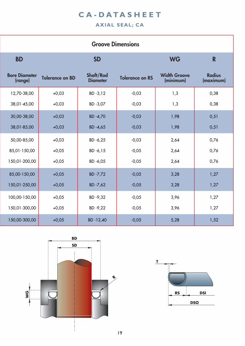
BD SD WG R
Bore Diameter (range) Tolerance on BD Shaft/Rod
Diameter Tolerance on RS Width Groove (minimum)
Radius (maximum)
12,70-38,00 +0,03 BD -3,12 -0,03 1,3 0,38
38,01-45,00 +0,03 BD -3,07 -0,03 1,3 0,38
30,00-38,00 +0,03 BD -4,70 -0,03 1,98 0,51
38,01-85,00 +0,03 BD -4,65 -0,03 1,98 0,51
50,00-85,00 +0,03 BD -6,25 -0,03 2,64 0,76
85,01-150,00 +0,05 BD -6,15 -0,05 2,64 0,76
150,01-200,00 +0,05 BD -6,05 -0,05 2,64 0,76
85,00-150,00 +0,05 BD -7,72 -0,05 3,28 1,27
150,01-250,00 +0,05 BD -7,62 -0,05 3,28 1,27
100,00-150,00 +0,05 BD -9,32 -0,05 3,96 1,27
150,01-300,00 +0,05 BD -9,22 -0,05 3,96 1,27
150,00-300,00 +0,05 BD -12,40 -0,05 5,28 1,52
Groove Dimensions
C A - D A T A S H E E TAXIAL SEAL; CA
SD
BD
DSO
DSIRS
T
WG
R
20
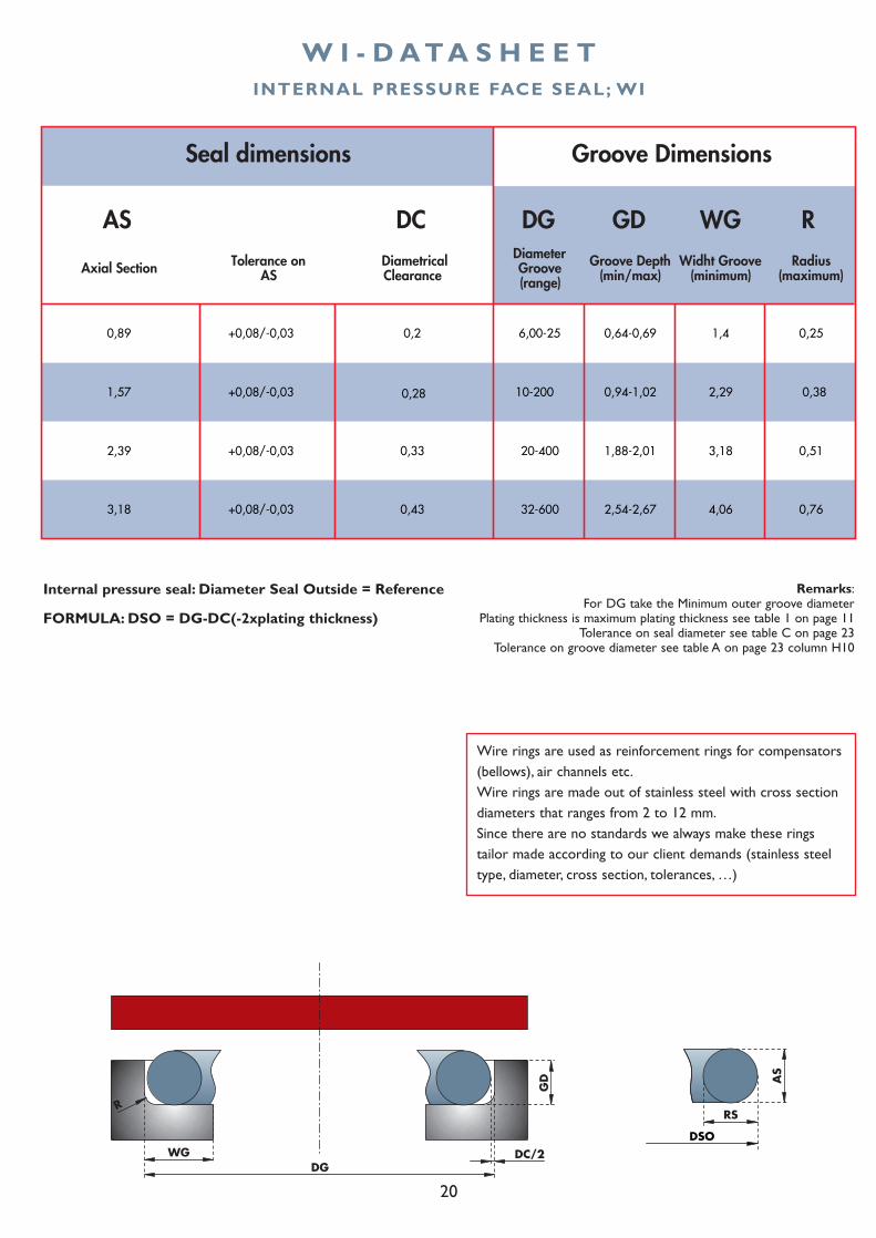
W I - D A T A S H E E T
AS DC DG GD WG R
Axial Section Tolerance on AS
Diametrical Clearance
Diameter Groove (range)
Groove Depth (min/max)
Widht Groove (minimum)
Radius (maximum)
0,89 0,2 6,00-25 0,64-0,69 1,4 0,25
1,57 10-200 0,94-1,02 2,29 0,38
2,39
3,18
Groove DimensionsSeal dimensions
32-600 4,062,54-2,67 0,76
0,513,180,33
0,43
1,88-2,0120-400
+0,08/-0,03
+0,08/-0,03
+0,08/-0,03
+0,08/-0,03
0,28
INTERNAL PRESSURE FACE SEAL; WI
Internal pressure seal: Diameter Seal Outside = Reference
FORMULA: DSO = DG-DC(-2xplating thickness)
AS
DGWG
R
GD
DC/2
RS
DSO
Remarks:For DG take the Minimum outer groove diameter
Plating thickness is maximum plating thickness see table 1 on page 11Tolerance on seal diameter see table C on page 23
Tolerance on groove diameter see table A on page 23 column H10
Wire rings are used as reinforcement rings for compensators(bellows), air channels etc.Wire rings are made out of stainless steel with cross sectiondiameters that ranges from 2 to 12 mm.Since there are no standards we always make these ringstailor made according to our client demands (stainless steeltype, diameter, cross section, tolerances, …)
21
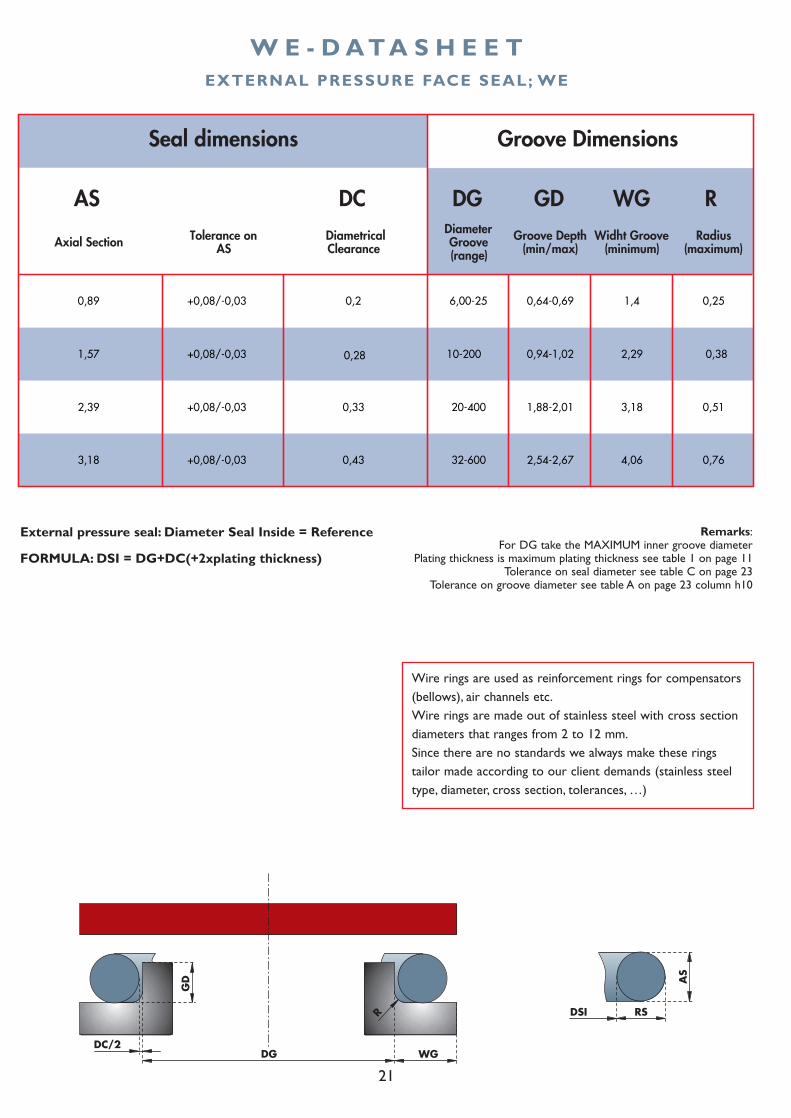
W E - D A T A S H E E T
AS DC DG GD WG R
Axial Section Tolerance on AS
Diametrical Clearance
Diameter Groove (range)
Groove Depth (min/max)
Widht Groove (minimum)
Radius (maximum)
0,89 0,2 6,00-25 0,64-0,69 1,4 0,25
1,57 10-200 0,94-1,02 2,29 0,38
2,39
3,18
Groove DimensionsSeal dimensions
32-600 4,062,54-2,67 0,76
0,513,180,33
0,43
1,88-2,0120-400
+0,08/-0,03
+0,08/-0,03
+0,08/-0,03
+0,08/-0,03
0,28
EXTERNAL PRESSURE FACE SEAL; WE
External pressure seal: Diameter Seal Inside = Reference
FORMULA: DSI = DG+DC(+2xplating thickness)
AS
RSDSI
DC/2
GD
R
DG WG
Remarks:For DG take the MAXIMUM inner groove diameter
Plating thickness is maximum plating thickness see table 1 on page 11Tolerance on seal diameter see table C on page 23
Tolerance on groove diameter see table A on page 23 column h10
Wire rings are used as reinforcement rings for compensators(bellows), air channels etc.Wire rings are made out of stainless steel with cross sectiondiameters that ranges from 2 to 12 mm.Since there are no standards we always make these ringstailor made according to our client demands (stainless steeltype, diameter, cross section, tolerances, …)
22
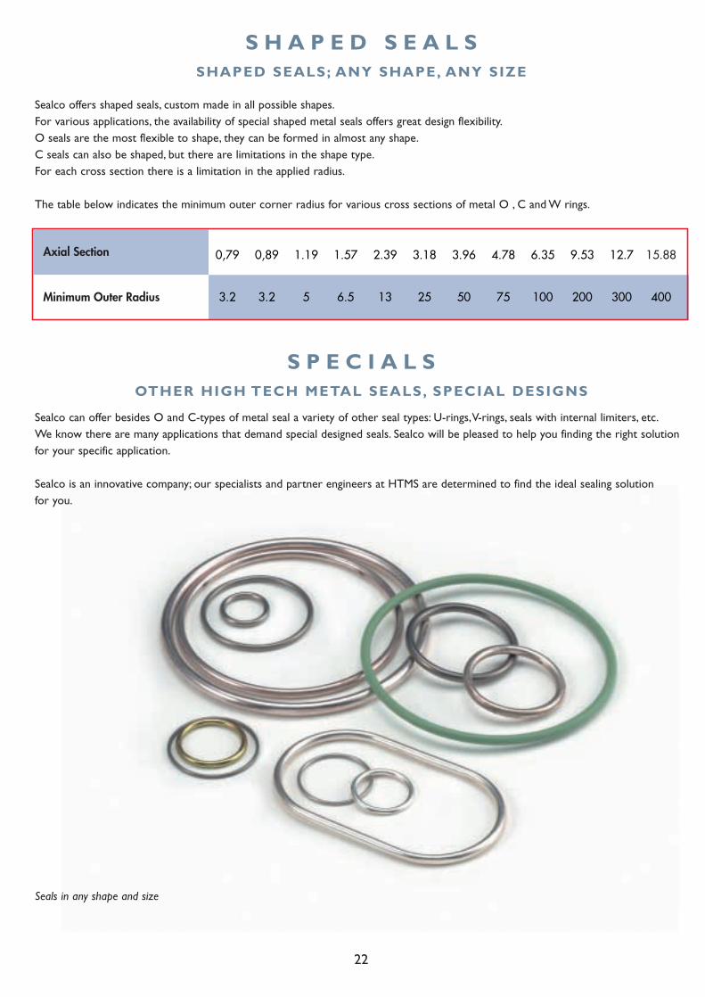
S H A P E D S E A L S
S P E C I A L S
Axial Section
Minimum Outer Radius 3.2 3.2 5 6.5 13 25 50 75 100 200 300 400
0,79 0,89 1.19 1.57 2.39 3.18 3.96 4.78 6.35 9.53 12.7 15.88
SHAPED SEALS; ANY SHAPE, ANY SIZE
Sealco offers shaped seals, custom made in all possible shapes.For various applications, the availability of special shaped metal seals offers great design flexibility.O seals are the most flexible to shape, they can be formed in almost any shape.C seals can also be shaped, but there are limitations in the shape type.For each cross section there is a limitation in the applied radius.
The table below indicates the minimum outer corner radius for various cross sections of metal O , C and W rings.
OTHER HIGH TECH METAL SEALS, SPECIAL DESIGNS
Seals in any shape and size
Sealco can offer besides O and C-types of metal seal a variety of other seal types: U-rings,V-rings, seals with internal limiters, etc.We know there are many applications that demand special designed seals. Sealco will be pleased to help you finding the right solutionfor your specific application.
Sealco is an innovative company; our specialists and partner engineers at HTMS are determined to find the ideal sealing solution for you.

23
T O L E R A N C E S
NominalDiameter
mm h10 H10
0-3 0 / -40 0 / +40
3-6 0 / -48 0 / +48
6-10 0 / -58 0 / +58
10-18 0 / -70 0 / +70
18-30 0 / -84 0 / +84
30-50 0 / -100 0 / +100
50-80 0 / -120 0 / +120
80-120 0 / -140 0 / +140
120-180 0 / -160 0 / +160
180-250 0 / -185 0 / +185
250-315 0 / -210 0 / +210
315-400 0 / -230 0 / +230
400-500 0 / -250 0 / +250
500-760 0 / -300 0 / +300
760-1050 0 / -400 0 / +400
1050-1425 0 / -500 0 / +500
1425-1940 0 / -630 0 / +630
Groove Tolerances
Tolerancesin µm
NominalDiameter
mm h11 H11
0-3 0 / -60 0 / +60
3-6 0 / -75 0 / +75
6-10 0 / -90 0 / +90
10-18 0 / -110 0 / +110
18-30 0 / -130 0 / +130
30-50 0 / -160 0 / +160
50-80 0 / -190 0 / +190
80-120 0 / -220 0 / +220
120-180 0 / -250 0 / +250
180-250 0 / -290 0 / +290
250-315 0 / -320 0 / +320
315-400 0 / -360 0 / +360
400-500 0 / -400 0 / +400
500-760 0 / -500 0 / +500
760-1050 0 / -630 0 / +630
1050-1425 0 / -760 0 / +760
1425-1940 0 / -1000 0 / +1000
C-Ring Tolerances
Tolerancesin µm
CrossSection(mm)
0,89-4,78
4.79-9.52
9.53-12.70 +250
O-Ring Tolerances on O-Ring Diameter
Tolerancesin µm
+ 130
+200
TABLE A TABLE B
TABLE C
24
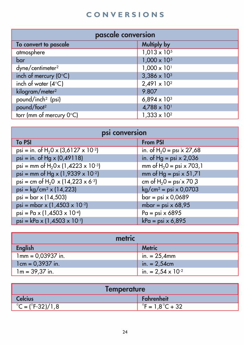
C O N V E R S I O N S
25
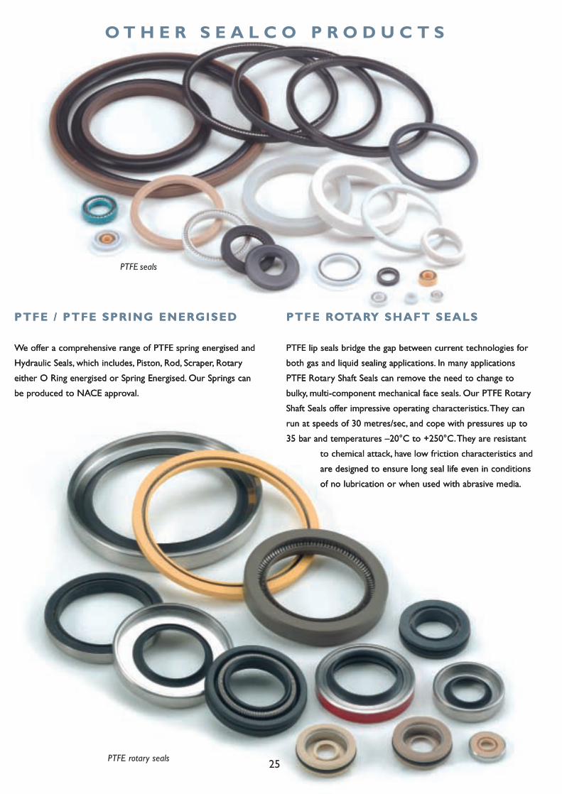
PTFE seals
PTFE rotary seals
PTFE / PTFE SPRING ENERGISED
We offer a comprehensive range of PTFE spring energised and
Hydraulic Seals, which includes, Piston, Rod, Scraper, Rotary
either O Ring energised or Spring Energised. Our Springs can
be produced to NACE approval.
PTFE ROTARY SHAFT SEALS
PTFE lip seals bridge the gap between current technologies for
both gas and liquid sealing applications. In many applications
PTFE Rotary Shaft Seals can remove the need to change to
bulky, multi-component mechanical face seals. Our PTFE Rotary
Shaft Seals offer impressive operating characteristics.They can
run at speeds of 30 metres/sec, and cope with pressures up to
35 bar and temperatures –20°C to +250°C.They are resistant
to chemical attack, have low friction characteristics and
are designed to ensure long seal life even in conditions
of no lubrication or when used with abrasive media.
PTFE / PTFE SPRING ENERGISED
We offer a comprehensive range of PTFE spring energised and
Hydraulic Seals, which includes, Piston, Rod, Scraper, Rotary
either O Ring energised or Spring Energised. Our Springs can
be produced to NACE approval.
O T H E R S E A L C O P R O D U C T S
PTFE ROTARY SHAFT SEALS
PTFE lip seals bridge the gap between current technologies for
both gas and liquid sealing applications. In many applications
PTFE Rotary Shaft Seals can remove the need to change to
bulky, multi-component mechanical face seals. Our PTFE Rotary
Shaft Seals offer impressive operating characteristics.They can
run at speeds of 30 metres/sec, and cope with pressures up to
35 bar and temperatures –20°C to +250°C.They are resistant
to chemical attack, have low friction characteristics and
are designed to ensure long seal life even in conditions
of no lubrication or when used with abrasive media.
26
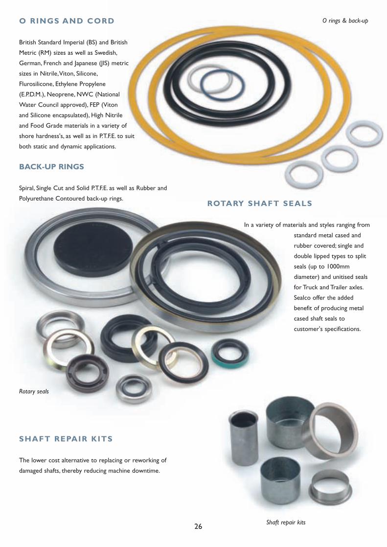
O rings & back-up
Rotary seals
Shaft repair kits
ROTARY SHAFT SEALS
In a variety of materials and styles ranging from
standard metal cased and
rubber covered; single and
double lipped types to split
seals (up to 1000mm
diameter) and unitised seals
for Truck and Trailer axles.
Sealco offer the added
benefit of producing metal
cased shaft seals to
customer's specifications.
SHAFT REPAIR KITS
The lower cost alternative to replacing or reworking of
damaged shafts, thereby reducing machine downtime.
O RINGS AND CORD
British Standard Imperial (BS) and British
Metric (RM) sizes as well as Swedish,
German, French and Japanese (JIS) metric
sizes in Nitrile,Viton, Silicone,
Flurosilicone, Ethylene Propylene
(E.P.D.M.), Neoprene, NWC (National
Water Council approved), FEP (Viton
and Silicone encapsulated), High Nitrile
and Food Grade materials in a variety of
shore hardness's, as well as in P.T.F.E. to suit
both static and dynamic applications.
BACK-UP RINGS
Spiral, Single Cut and Solid P.T.F.E. as well as Rubber and
Polyurethane Contoured back-up rings.
27
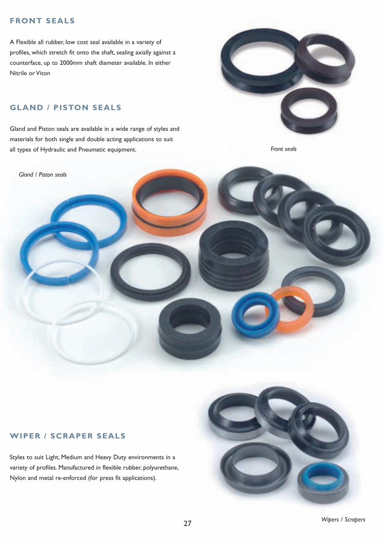
FRONT SEALS
A Flexible all rubber, low cost seal available in a variety of
profiles, which stretch fit onto the shaft, sealing axially against a
counterface, up to 2000mm shaft diameter available. In either
Nitrile or Viton
GLAND / PISTON SEALS
Gland and Piston seals are available in a wide range of styles and
materials for both single and double acting applications to suit
all types of Hydraulic and Pneumatic equipment.
Gland / Piston seals
WIPER / SCRAPER SEALS
Styles to suit Light, Medium and Heavy Duty environments in a
variety of profiles. Manufactured in flexible rubber, polyurethane,
Nylon and metal re-enforced (for press fit applications).
Wipers / Scrapers
Front seals
1645 Pershore Road
Stirchley, Birmingham B30 3DR
t: 0121 451 2875 f: 0121 458 3153
w: www.sealco.co.uk
Mill House, Priory Road North,
Dartford, Kent DA1 2BZ
t: 01322 223425 f: 01322 223429
w: www.sealco.co.uk