Embed Size (px)
Citation preview

Dick Ennis TCCI Manufacturing
The Compressor ClutchTorque Transfer and Beyond
Purpose
To provide background and history of AC compressor clutches
Discuss different designs and components
Provide information and diagnostics relating to clutch related failure modes. Give some service tips for field technicians

In preparing this presentation I found it fascinating that most folks don’tpay much attention to the compressor clutch and treat it as an afterthoughtwhen discussing compressors. The clutch must survive extreme temperaturechanges, high energy forces, be impervious to chemicals and moisture, andfunction under the entire RPM range of the engine. As the clutch is the onlypart of the compressor assembly that actually “wears out” then designs must consider the expected product life specified by the customer.The clutch has one more feature that is seldom considered and that being thedampening of the compressor engagement in which rotational energy is transferred to axial compression. Without this feature the compressor wouldlock up immediately as the internal component geometries and materials couldnot sustain the engagement inertia loads.Based on the importance of the requirements for such a dynamic assembly Ibelieve it’s time to pay homage to the “Rodney Dangerfield” of AC parts.
Clutch Overview

A compressor clutch provides the means of torque transfer from the engine FEAD (Front End Accessory Drive) to the compressor rotating assembly. Electromagnetic clutches operate
electrically but transmit torque mechanically.Since the clutches started becoming
popular over 60 years ago, the variety of applications and clutch designs has increased dramatically, but the basic operation remains the same today.
What Is a Compressor Clutch?
The ability of the clutch to engage and disengage is critical on several levels.
1.Primarily to stop compressor operation when the cooling demand in the cabin is satisfied. If not disengaged when this occurs a phenomena known as “evaporator freeze” happens. Airflow becomes obstructed under these conditions.
2.Secondly there are conditions that occur in an AC system of which the compressor operation needs to cease.
a.Excessive Discharge Pressureb.Low Refrigerant Chargec.In some instances High Discharge Gas Temperature
3.Thirdly the ECM (engine control module) needs to disrupt compressor operation due to abnormal engine operating parameters such as Engine Overheating.
Why do we need a Compressor Clutch?

1940 Packard AC Compressor
In 1939 Packard became the first automotive manufacturer to offer AC in it’s cars. These were manufactured by Bishop and Babcock Company of Cleveland Ohio. Cars ordered with the “Weather Conditioner” were shipped from the Packard facility to the B&B factory for installation. When complete the car was sent directly to the dealer.
It was not commercially successful for a number of reasons:1. The Evaporator and Fan took up half of the trunk space2. It was superseded by more efficient systems in the post war years3. There was NO SHUT OFF as the compressor operated continuously4. The several feet of plumbing going back and forth between the engine
compartment and the trunk proved unreliable in service5. The price of $274 dollars ($4,692 in 2014 US dollars) was unaffordable
to most people

1953 Chrysler Airtemp Compressor
In 1953 Chrysler produced the Imperial which was one of the first production cars in 12 years to offer modern automotive AC as an option. The Chrysler Airtemp system was more advanced and had the highest capacity available at the time. As can be seen by the picture on the right it too did not use a clutch.
It was operated by a single switch on the dash and had low, medium and high settingsIt drew in more outside air than the contemporary systems thus reducing the
staleness associated with automotive AC at the timeSmall ducts directed cool air towards the ceiling where it filtered down on the
occupants instead of blowing directly on them

1954 Nash Ambassador
In 1954 Nash Motors company using its Kelvinator refrigeration experience created the automobile industry's first single-unit heating and air conditioning system. This was a compact, affordable system for the mass market with controls on the dash and an electric clutch.
It was the first system to have an HEB unit mounted in the cowl and in theengine compartment and also the use of a thermostatically controlledElectromagnetic clutch

1954 Nash Rambler

How does the clutch work?
A normal AC compressor clutch uses n=3 different key components
Armature – coupled directly to the compressor shaft to transfer the rotational torque from the pulley to the compressor
Rotor or Pulley – Belt driven and coupled to the engine drive train
Coil – Electrically connected to the AC relay and produces an electromagnetic field when energized

Coupled to the compressor shaft using either a key or a spline. It’s comprised of several parts, first the hub which connects to the compressor. Second the springs which connect the hub to the friction plate, these “springs” can be steel or rubber. Lastly the friction plate which mates directly to the pulley friction surface.
Armature

Normally mounted on the compressor nose the rotor is 100% connected to the accessory drive train using the drive belt. It has n=2 basic parts, the rotor and the rotor bearing which is a sealed 2-row bearing.
Rotor
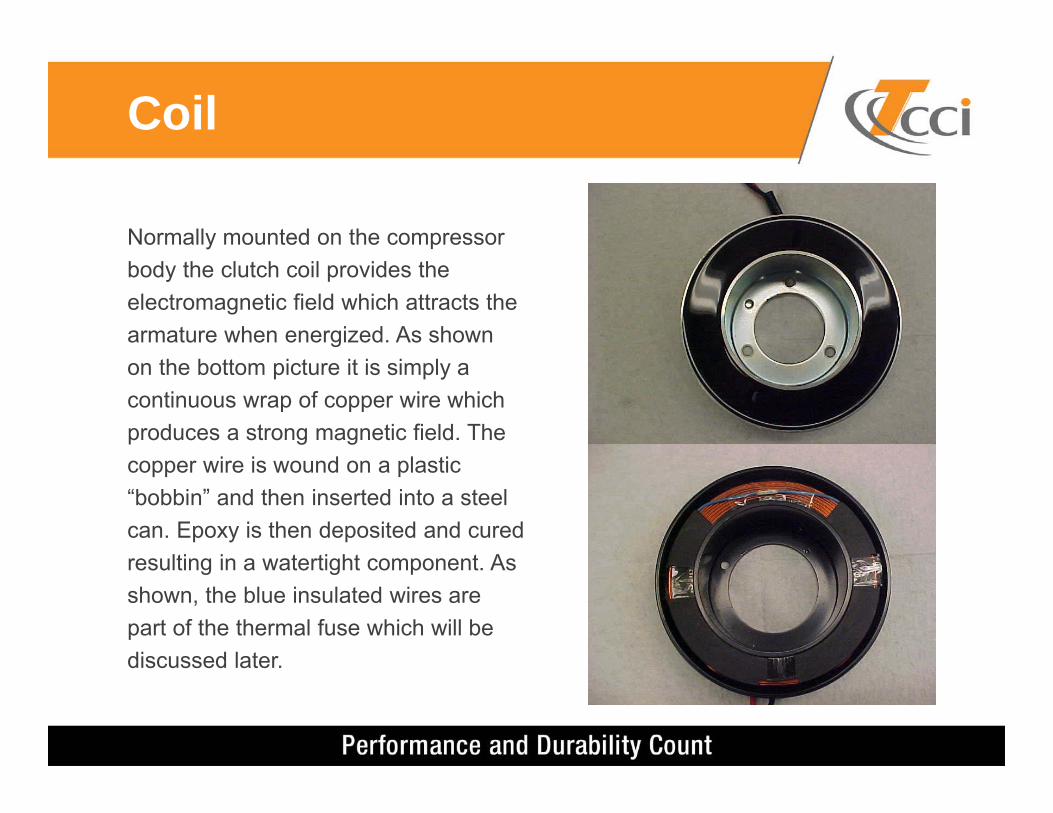
Normally mounted on the compressor body the clutch coil provides the electromagnetic field which attracts the armature when energized. As shown on the bottom picture it is simply a continuous wrap of copper wire which produces a strong magnetic field. The copper wire is wound on a plastic “bobbin” and then inserted into a steel can. Epoxy is then deposited and cured resulting in a watertight component. As shown, the blue insulated wires are part of the thermal fuse which will be discussed later.
Coil
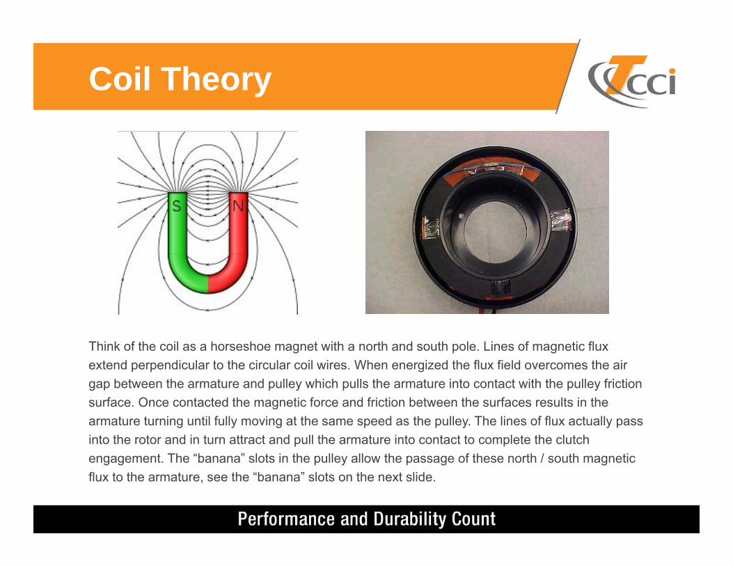
Think of the coil as a horseshoe magnet with a north and south pole. Lines of magnetic flux extend perpendicular to the circular coil wires. When energized the flux field overcomes the air gap between the armature and pulley which pulls the armature into contact with the pulley friction surface. Once contacted the magnetic force and friction between the surfaces results in the armature turning until fully moving at the same speed as the pulley. The lines of flux actually pass into the rotor and in turn attract and pull the armature into contact to complete the clutch engagement. The “banana” slots in the pulley allow the passage of these north / south magnetic flux to the armature, see the “banana” slots on the next slide.
Coil Theory

Pulley Features
Banana Slots in pulleyArmature surface showing friction
plate, center hub and attachment rivets
Friction Plate Center Hub
Rivets
Armature Features

Clutch as Mounted

Clutch as Mounted
Armature Pulley(Rotor) Coil
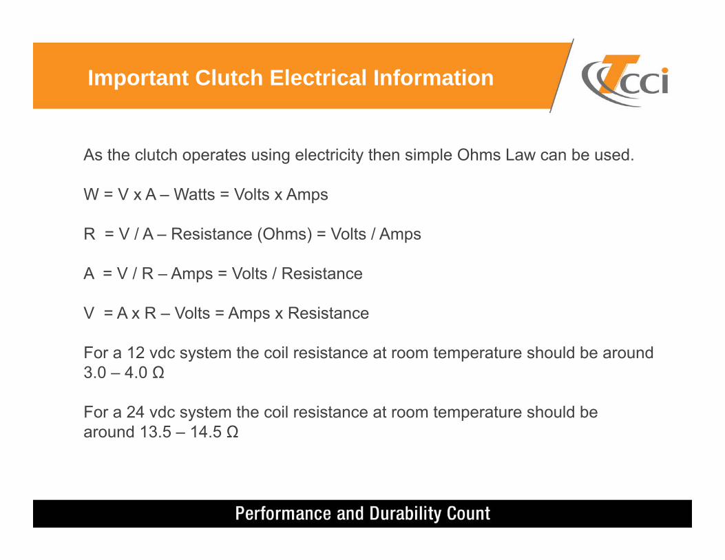
As the clutch operates using electricity then simple Ohms Law can be used.
W = V x A – Watts = Volts x Amps
R = V / A – Resistance (Ohms) = Volts / Amps
A = V / R – Amps = Volts / Resistance
V = A x R – Volts = Amps x Resistance
For a 12 vdc system the coil resistance at room temperature should be around 3.0 – 4.0 Ω
For a 24 vdc system the coil resistance at room temperature should bearound 13.5 – 14.5 Ω
Important Clutch Electrical Information

Gage Line is defined as the distance from the front compressor mount hole centerline to the center ribas shown
Bearing offset is the distancebetween the bearing centerlineand the pulley centerline
Gage Line and Bearing Offset

Think of the clutch magnet as being basically a coil. When the power is cut,the collapsing magnetic field creates a high voltage discharge. A diodeis basically a one way valve for electricity, the normal power can passthrough to energize the coil, but the induced backflow voltage is blocked.The diode is wired in parallel with the clutch coil and normally can be foundinside of the coil either at the junction box where the wires enter the coil orinternally inside of the coil.The diode is polarity sensitive meaning if a supply voltage is providedopposite (think of jump starting a car with reverse polarity) then the diode willfail. There are n=2 failure modes, either the diode becomes shorted or itbecomes open. A shorted diode will result in extremely low resistance whenmeasured with a Multimeter (0-0.3 ohms) and will cause the fuse to openwhen the clutch is energized. If the diode opens due to reverse polarity thenit is not measureable using the Multimeter but can damage the solid state ACrelay due to voltage spikes. See the next slide.
Why does the Clutch Use a Diode?
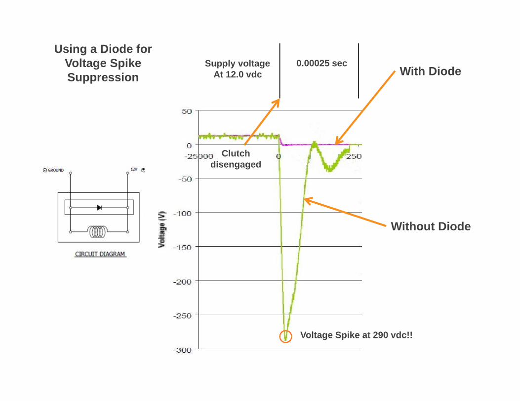
With Diode
Without Diode
0.00025 sec
Voltage Spike at 290 vdc!!
Using a Diode forVoltage Spike Suppression
Clutch disengaged
Supply voltageAt 12.0 vdc

A Thermal Fuse is a small fusible link installed in the clutch circuit in series with the coil windings. It’s positioned at the coil face (closest to the rotor) and just under the epoxy fill. It has a pre-determined value by which if exceeded will cause the fuse to open disrupting the clutch coil electrical circuit. The setting normally is ~ 187 deg C (367 degF). When a compressor OR clutch fail due to slippage between the friction surfaces the heat generated is quite high and the T-fuse will open preventing loss of the drive belt allowing the vehicle to continue without AC until the system can get serviced.
What is a Thermal Fuse?Close-up inside of a Thermal Fuse showing melted
fusible linkPicture showing Thermal fuse at the coil face

“Leaf” Spring Clutch Engagement“Leaf” Spring Clutch Engagement

“Leaf” Spring Clutch Engagement“Super Heavy Duty” Spring Clutch Engagement

Super Heavy Duty “Ring” Spring
“Wagon Wheel”“Dust Cover”
“3 Eye”
“Sealed”
Different Types of Clutches
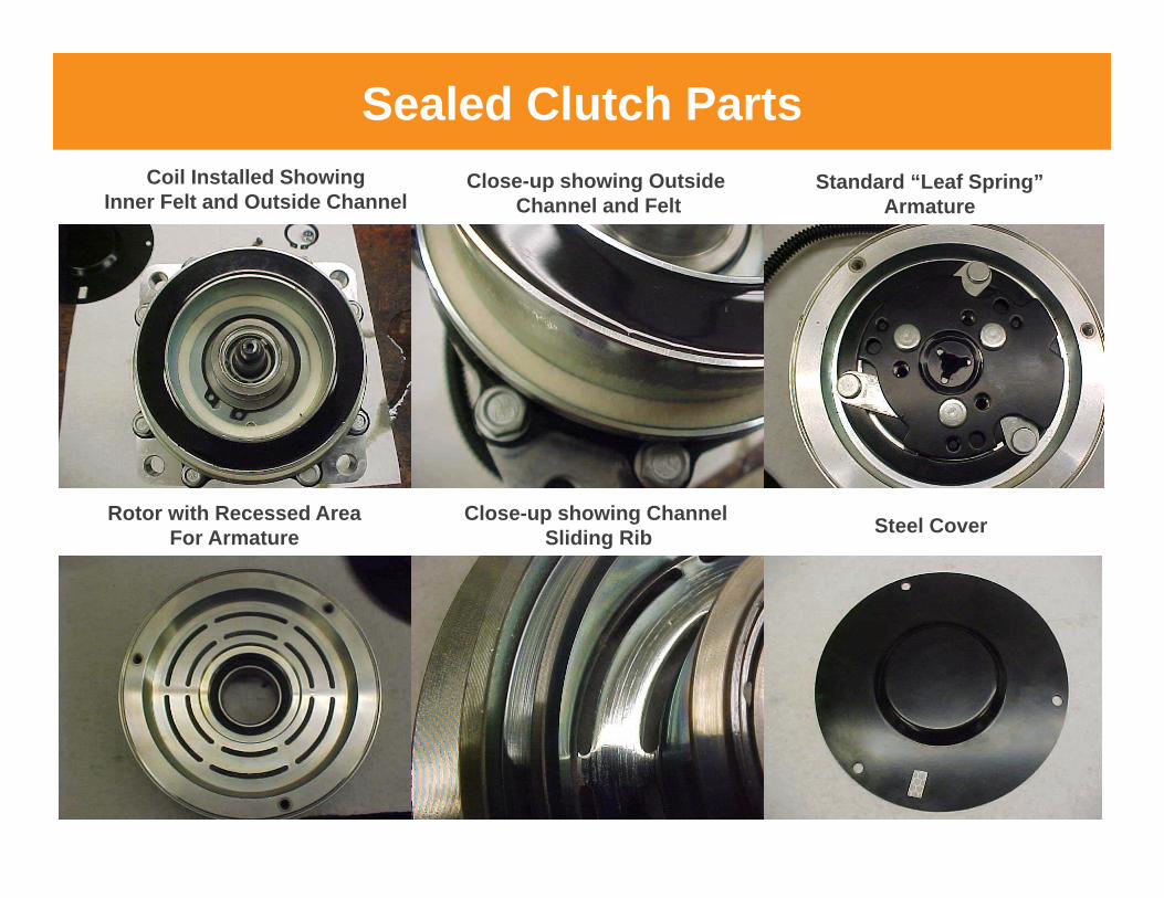
Sealed Clutch PartsCoil Installed Showing
Inner Felt and Outside ChannelClose-up showing Outside
Channel and FeltStandard “Leaf Spring”
Armature
Rotor with Recessed AreaFor Armature
Close-up showing Channel Sliding Rib Steel Cover

Check the airgap between the armature and pulley using a feeler gagewith the engine shut off as shown below
You should check this at the beginning of the season, nominal airgapsettings can vary between 0.3 mm to 0.8 mm (0.012” – 0.031”). If thegap exceeds 1.0 mm (0.04”) then consider changing the clutch assemblyAs the wear is on the upper allowable limit of1.2 mm (0.47”).
Service Suggestion #1

Look at the clutch paint on the armature, if it appears burnt or highlydiscolored than the compressor or clutch are in failure mode.
Service Suggestion #2
Rotate the armature by hand and feel for grinding or if it doesn’t turn. Check system charge Confirm Air Gap Start the vehicle, engage the clutch, if slipping shut down immediately
and determine if the clutch is worn out or is the compressor failed

Look at the clutch wires for exposed wire, this could be due torubbing or heat.
If conductor is exposed repair it and wrap it with electrical tapeor wire “shrink wrap”
Service Suggestion #3

Service Suggestion #4 If using a sealed clutch, remove the cover and blow out the clutch
dust using compressed air. Use a respirator and eye protection.
Sealed clutches trap “clutch dust” which is trapped due to theenhanced sealing of the friction surfaces. Although excellent forkeeping out dirt and contamination it also traps all clutch wear residue.

If you check the supply voltage and it’s less than battery voltagethere is a voltage drop in the circuit.
This problem is mostly caused on single clutch wire applications in whichthe compressor body provides the ground to complete the circuit. As theindustry has moved to “powder coat paint” on the compressor mountbrackets the required “metal to metal” contact is suspect. Add a groundstrap as needed from the compressor body to engine ground.
Service Suggestion #5

Check your drive belt for cracking or splitting in either the ribsor belt backing. Also, look for wear in the ribs.
One of the most common and preventable problems with the FEAD isthe drive belt failing. As it becomes worn or damaged it can allowslippage (particularly on wet days) which can impact every accessoryincluding the compressor.
Service Suggestion #6

Review the compressor pulley for any oily residue, the pattern to see is depicted below.
When either the shaft seal or pulley bearing grease seal are failingthe oil or grease are flung outward from the centerline of theassembly. This indicates an impending failure which needs immediateattention. If it’s the grease seal then replacing the clutch can savecompressor replacement.
Service Suggestion #7

Thank You!
Questions?