Embed Size (px)
Citation preview
National Aeronautics andSpace Administration
NASA Technical Memorandum 104260
The Constant Current Loop: A New Paradigm for Resistance Signal Conditioning
Karl F. Anderson
October 1992
National Aeronautics andSpace Administration
Dryden Flight Research Facility
Edwards, California 93523-0273
1992
NASA Technical Memorandum 104260
The Constant Current Loop: A New Paradigm for Resistance Signal Conditioning
Karl F. Anderson
NASA Dryden Flight Research Facility, Edwards, California
CONTENTS
ABSTRACT 1
NOMENCLATURE 1
INTRODUCTION 2
THE WHEATSTONE BRIDGE 3Background . . . . . . . . . . . . . . . . . . . . . . . . . . . . . . . . . . . . . . . . . . . . . . . . . . . . . . . . . . . . . . . . . . . . . 3Theory of Operation . . . . . . . . . . . . . . . . . . . . . . . . . . . . . . . . . . . . . . . . . . . . . . . . . . . . . . . . . . . . . . 3Disadvantages . . . . . . . . . . . . . . . . . . . . . . . . . . . . . . . . . . . . . . . . . . . . . . . . . . . . . . . . . . . . . . . . . . . 4
FOUR-TERMINAL VOLTAGE DIFFERENCE MEASUREMENT 5
THE CONSTANT CURRENT LOOP 6Theory of Operation . . . . . . . . . . . . . . . . . . . . . . . . . . . . . . . . . . . . . . . . . . . . . . . . . . . . . . . . . . . . . . 6Advantages . . . . . . . . . . . . . . . . . . . . . . . . . . . . . . . . . . . . . . . . . . . . . . . . . . . . . . . . . . . . . . . . . . . . . 7Circuit Features. . . . . . . . . . . . . . . . . . . . . . . . . . . . . . . . . . . . . . . . . . . . . . . . . . . . . . . . . . . . . . . . . . 9Disadvantages . . . . . . . . . . . . . . . . . . . . . . . . . . . . . . . . . . . . . . . . . . . . . . . . . . . . . . . . . . . . . . . . . . . 9Circuit Component Requirements. . . . . . . . . . . . . . . . . . . . . . . . . . . . . . . . . . . . . . . . . . . . . . . . . . . . 9Experimental Results . . . . . . . . . . . . . . . . . . . . . . . . . . . . . . . . . . . . . . . . . . . . . . . . . . . . . . . . . . . . 10
STRAIN-GAGE ROSETTE MEASUREMENTS 11
SIMULTANEOUS RESISTANCE AND TEMPERATURE MEASUREMENTS 13
CONCLUSIONS 15
REFERENCES 16
iii
FIGURES
1. Single active arm Wheatstone bridge circuit . . . . . . . . . . . . . . . . . . . . . . . . . . . . . . . . . . . . . . . . . . 4
2. Current loop circuit for one-gage resistance . . . . . . . . . . . . . . . . . . . . . . . . . . . . . . . . . . . . . . . . . . 6
3. A practical current loop circuit for one remote gage resistance . . . . . . . . . . . . . . . . . . . . . . . . . . . 8
4. Strain-gage rosette measurement using current loop signal conditioning with six leadwires . . . . . . . . . . . . . . . . . . . . . . . . . . . . . . . . . . . . . . . . . . . . . . . . . . . . . . . . . . . . . . . . . . . . . . . . 12
5. A practical strain-gage rosette measurement circuit using current loop signal conditioningwith six lead wires. . . . . . . . . . . . . . . . . . . . . . . . . . . . . . . . . . . . . . . . . . . . . . . . . . . . . . . . . . . . . . 13
6. Reversing constant current loop signal conditioning, which separates resistance changesand voltage outputs into independent data channels . . . . . . . . . . . . . . . . . . . . . . . . . . . . . . . . . . . 14
iv
par·a·digm, n.[ < Fr. < LL. <Gr. para, beside + deigma, example < deiknynai, to show], 1. a pattern,example or model.
Websters New World Dictionary, Concise Edition Meridian Books, 1960.
ABSTRACT
A practical single constant current loop circuit for the signal conditioning of variable resistancetransducers has been synthesized, analyzed, and demonstrated. The strain gage and the resistancetemperature device are examples of variable resistance sensors. Lead wires connect variable resistancesensors to remotely located signal conditioning hardware. The presence of lead wires in the conventionalWheatstone bridge signal conditioning circuit introduces undesired effects that reduce the quality of thedata from the remote sensors. A practical approach is presented for suppressing essentially all lead wireresistance effects while indicating only the change in resistance value. Theoretical predictions supportedby laboratory testing confirm the following features of the approach: (1) dc response; (2) the electricaloutput is unaffected by extremely large variations in the resistance of any or all lead wires; (3) theelectrical output remains zero for no change in gage resistance; (4) the electrical output is inherentlylinear with respect to gage resistance change; (5) the sensitivity is double that of a Wheatstone bridgecircuit; and (6) the same excitation wires can serve multiple independent gages. An adaptation ofcurrent loop circuit is presented that simultaneously provides an output signal voltage directlyproportional to transducer resistance change and provides temperature information that is unaffected bytransducer and lead wire resistance variations. These innovations are the subject of NASA patentapplications.
NOMENCLATURE
dc direct current
eo output voltage for Wheatstone bridge circuits, volts
Ex excitation voltage for Wheatstone bridge circuits, volts
GF gage factor
I current level, amperes
IA, IB directions of transducer current flow
M measuring system for voltage difference
R initial resistance of a transducer (strain gage, RTD, etc.), ohms
∆R change in gage resistance due to the quantity being sensed, ohms
Rcal shunt calibration resistance, ohms
Rg gage resistance, ohms
Rref Reference resistance, essentially equal to R, ohms
Rw Lead wire resistance, ohms
RTD resistance temperature device
S calibration switch
V Voltage source for constant current regulation
VA, VB Voltage outputs from IA and IB, respectively
Vg Voltage across gage resistances
Vout Voltage output from voltage difference measuring system
Vref Voltage across a reference resistance
V+ Positive thermoelectric (or other dc) voltage
V– Negative thermoelectric (or other dc) voltage
INTRODUCTION
Variable resistance devices are convenient to use as transducers. Two common examples are thevariable resistance strain gage and the resistance temperature device (RTD). All variable resistancetransducers change resistance in response to a change in the sensitive parameter. When the change inresistance is a small percentage of the total transducer resistance, the signal conditioning task becomesmore of a challenge. A strain gage is an example of a transducer that exhibits these characteristics. Thesignificant output of a strain gage is the small resistance change, ∆R, that occurs in an initial resistance,R, as mechanical strain changes the dimensions of the gage. This small ∆R is typically no greater than0.1 to 0.5 percent of R, which ranges typically from 120 to 1000 Ω.
The small magnitude of ∆R causes two general problems: the basic need to detect the small ∆Rin the presence of the much larger initial gage resistance and the need to detect the desired ∆R in thepresence of other parasitic resistance changes. Lead wire resistance changes, for example, can easilybe larger than ∆R, especially where extreme temperature variations exist during a test. Serious errorsdue to lead wire resistance effects are common in the data from high-temperature strain measurements.High-temperature tests, such as those involving reentry simulations or operating turbine engines, ofteninvolve temperatures in excess of 1,000 °F. References 1 and 2 point out the continuing need to dealwith lead wire resistance effects, especially where testing involves extreme temperature changes.
The Wheatstone bridge, in various circuit forms, is the traditional circuit used to signal conditionvariable resistance transducers such as strain gages and RTDs. Although the Wheatstone bridge hasbeen used effectively for many years in the signal conditioning role, it has some disadvantages in manysituations that can be overcome by a constant current loop approach. The constant current loop approachpresented here is insensitive to any lead wire resistance changes, the basic cause of problems when theWheatstone bridge is used as a resistance signal conditioning circuit for single remote resistances.Diagrams and equations, along with test data from a practical circuit, are presented to illustrate theprinciple of operation. An approach for including several transducers (such as a strain-gage rosette) inthe same constant current loop is presented. Each transducer in the loop has an independent output forindication and recording. Finally, an adaptation of this circuit is presented that simultaneously deliversboth transducer resistance change and transducer temperature when thermocouple wire is used with asingle-gage resistance in a four-wire circuit.
2
THE WHEATSTONE BRIDGE
A basic function of the Wheatstone bridge as a signal conditioner is to transform the small resistancechange of the variable resistance transducer into a proportional voltage signal. The Wheatstone bridgewas originally presented in reference 3.
Background
The Wheatstone bridge does an excellent job of subtracting two large voltages to yield an outputvoltage due to ∆R, the change in resistance. The Wheatstone bridge output, however, is inherentlynonlinear for resistance changes in a single arm, and current carrying lead wire resistances necessarilyappear in the loop of the bridge circuit where they always reduce sensitivity and can cause zero shifts.Sir Charles Wheatstone states in reference 3, “Slight differences in the lengths and even in the tensionsof the wires are sufficient to disturb the equilibrium [of my circuit].” Lead wire resistance effectsare usually manageable for tests that involve moderate changes in lead wire and connector resistances.Wheatstone bridge embodiments exist that reduce lead wire effects at the expense of added complexityin the signal conditioning circuitry or additional lead wires or both. Reference 4 discusses using aWheatstone bridge with three lead wires connecting to a remote strain-gage resistance in a way thatminimizes the effects of lead wire resistance variations.
A variation of the Wheatstone bridge described in reference 5 deals with lead wire resistanceproblems by replacing two resistance arms in the bridge with constant current sources. A fourth leadwire is used, and a third constant current source is employed to force the current to be zero in whatwould otherwise be a current carrying lead wire. This tri-current method effectively tolerates leadwire resistance changes, delivers a linear output, and doubles sensitivity. Four lead wires, however,rather than three per measurement channel and three separate constant current sources that deliver veryclosely matched currents are required to obtain acceptable stability for strain measurements. The wiring,stability, and tracking requirements result in costs that have limited the application of the tri-currentsignal conditioning technique.
Theory of Operation
The classic Wheatstone bridge circuit in figure 1 performs a precise analog subtraction of voltagedrops across the various resistances in the loop of the bridge. This is done in a way that reliablyisolates extremely small differences in large voltage drops. Commonly, microvolt (µV) level outputsare obtained from individual voltage drops of several volts. An ideal circuit is achieved for observingsmall variations in large resistances, especially when a minimum of parasitic lead wire resistance withinthe loop of the bridge is present.
The Wheatstone bridge circuit acts as an analog computation circuit. The excitation level serves asa multiplier to the circuit output, and variations in the four individual arms add to and subtract from theoutput according to their location in the circuit.
3
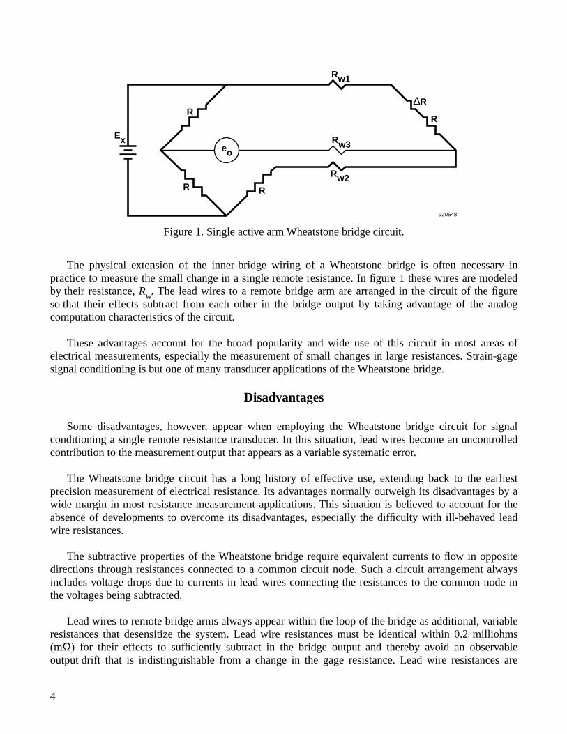
Figure 1. Single active arm Wheatstone bridge circuit.
The physical extension of the inner-bridge wiring of a Wheatstone bridge is often necessary inpractice to measure the small change in a single remote resistance. In figure 1 these wires are modeledby their resistance, Rw. The lead wires to a remote bridge arm are arranged in the circuit of the figureso that their effects subtract from each other in the bridge output by taking advantage of the analogcomputation characteristics of the circuit.
These advantages account for the broad popularity and wide use of this circuit in most areas ofelectrical measurements, especially the measurement of small changes in large resistances. Strain-gagesignal conditioning is but one of many transducer applications of the Wheatstone bridge.
Disadvantages
Some disadvantages, however, appear when employing the Wheatstone bridge circuit for signalconditioning a single remote resistance transducer. In this situation, lead wires become an uncontrolledcontribution to the measurement output that appears as a variable systematic error.
The Wheatstone bridge circuit has a long history of effective use, extending back to the earliestprecision measurement of electrical resistance. Its advantages normally outweigh its disadvantages by awide margin in most resistance measurement applications. This situation is believed to account for theabsence of developments to overcome its disadvantages, especially the difficulty with ill-behaved leadwire resistances.
The subtractive properties of the Wheatstone bridge require equivalent currents to flow in oppositedirections through resistances connected to a common circuit node. Such a circuit arrangement alwaysincludes voltage drops due to currents in lead wires connecting the resistances to the common node inthe voltages being subtracted.
Lead wires to remote bridge arms always appear within the loop of the bridge as additional, variableresistances that desensitize the system. Lead wire resistances must be identical within 0.2 milliohms(mΩ) for their effects to sufficiently subtract in the bridge output and thereby avoid an observableoutput drift that is indistinguishable from a change in the gage resistance. Lead wire resistances are
920648
Rw1
∆R
R
Rw3
Rw2RR
R
Exeo
4
uncontrolled in the usual test environment, and the resistance variation is much larger in test situationsinvolving high temperatures.
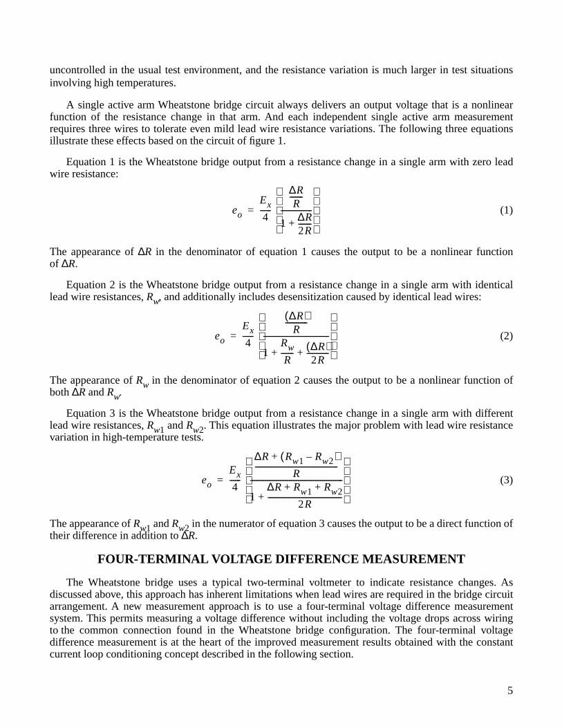
A single active arm Wheatstone bridge circuit always delivers an output voltage that is a nonlinearfunction of the resistance change in that arm. And each independent single active arm measurementrequires three wires to tolerate even mild lead wire resistance variations. The following three equationsillustrate these effects based on the circuit of figure 1.
Equation 1 is the Wheatstone bridge output from a resistance change in a single arm with zero leadwire resistance:
(1)
The appearance of ∆R in the denominator of equation 1 causes the output to be a nonlinear functionof ∆R.
Equation 2 is the Wheatstone bridge output from a resistance change in a single arm with identicallead wire resistances, Rw, and additionally includes desensitization caused by identical lead wires:
(2)
The appearance of Rw in the denominator of equation 2 causes the output to be a nonlinear function ofboth ∆R and Rw.
Equation 3 is the Wheatstone bridge output from a resistance change in a single arm with differentlead wire resistances, Rw1 and Rw2. This equation illustrates the major problem with lead wire resistancevariation in high-temperature tests.
(3)
The appearance of Rw1 and Rw2 in the numerator of equation 3 causes the output to be a direct function oftheir difference in addition to ∆R.
FOUR-TERMINAL VOLTAGE DIFFERENCE MEASUREMENT
The Wheatstone bridge uses a typical two-terminal voltmeter to indicate resistance changes. Asdiscussed above, this approach has inherent limitations when lead wires are required in the bridge circuitarrangement. A new measurement approach is to use a four-terminal voltage difference measurementsystem. This permits measuring a voltage difference without including the voltage drops across wiringto the common connection found in the Wheatstone bridge configuration. The four-terminal voltagedifference measurement is at the heart of the improved measurement results obtained with the constantcurrent loop conditioning concept described in the following section.
eo
Ex
4------
∆RR
-------
1 ∆R2R-------+
-----------------
=
eo
Ex
4------
∆R( )R
------------
1Rw
R------- ∆R( )
2R------------+ +
------------------------------------
=
eo
Ex
4------
∆
R R
w
1
R
w
2
–
( )
+
R
---------------------------------------------
1
∆ R R
w
1
R
w
2
+ +
2
R
----------------------------------------+
--------------------------------------------------
=
5
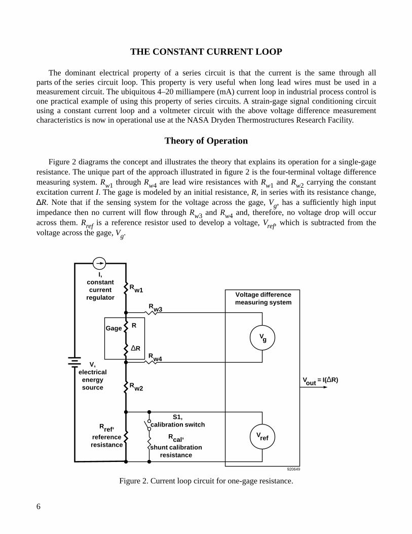
THE CONSTANT CURRENT LOOP
The dominant electrical property of a series circuit is that the current is the same through allparts of the series circuit loop. This property is very useful when long lead wires must be used in ameasurement circuit. The ubiquitous 4–20 milliampere (mA) current loop in industrial process control isone practical example of using this property of series circuits. A strain-gage signal conditioning circuitusing a constant current loop and a voltmeter circuit with the above voltage difference measurementcharacteristics is now in operational use at the NASA Dryden Thermostructures Research Facility.
Theory of Operation
Figure 2 diagrams the concept and illustrates the theory that explains its operation for a single-gageresistance. The unique part of the approach illustrated in figure 2 is the four-terminal voltage differencemeasuring system. Rw1 through Rw4 are lead wire resistances with Rw1 and Rw2 carrying the constantexcitation current I. The gage is modeled by an initial resistance, R, in series with its resistance change,∆R. Note that if the sensing system for the voltage across the gage, Vg, has a sufficiently high inputimpedance then no current will flow through Rw3 and Rw4 and, therefore, no voltage drop will occuracross them. Rref is a reference resistor used to develop a voltage, Vref, which is subtracted from thevoltage across the gage, Vg.
6
Figure 2. Current loop circuit for one-gage resistance.
920649
I, constant current
regulator
V, electrical energy source
Rref,
reference resistance
S1, calibration switch
Rcal,
shunt calibration resistance
Rw2Vout = I(∆R)
Voltage difference measuring system
Rw4
Rw3
∆R
RGage
Rw1
Vref
Vg
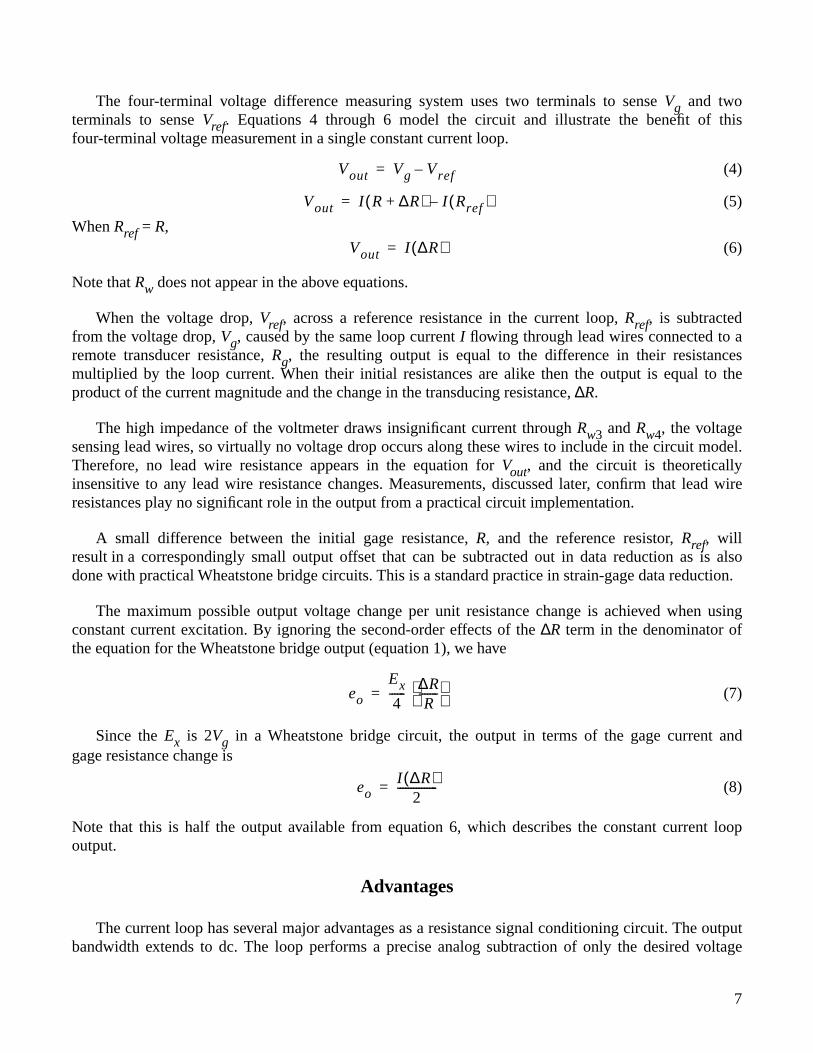
The four-terminal voltage difference measuring system uses two terminals to sense
V
g
and twoterminals to sense
V
ref
. Equations 4 through 6 model the circuit and illustrate the benefit of thisfour-terminal voltage measurement in a single constant current loop.
(4)
(5)
When
R
ref
=
R
,(6)
Note that
R
w
does not appear in the above equations.
When the voltage drop,
V
ref
, across a reference resistance in the current loop,
R
ref
, is subtractedfrom the voltage drop,
V
g
, caused by the same loop current
I
flowing through lead wires connected to aremote transducer resistance,
R
g
, the resulting output is equal to the difference in their resistancesmultiplied by the loop current. When their initial resistances are alike then the output is equal to theproduct of the current magnitude and the change in the transducing resistance,
∆
R.
The high impedance of the voltmeter draws insignificant current through Rw3 and Rw4, the voltagesensing lead wires, so virtually no voltage drop occurs along these wires to include in the circuit model.Therefore, no lead wire resistance appears in the equation for Vout, and the circuit is theoreticallyinsensitive to any lead wire resistance changes. Measurements, discussed later, confirm that lead wireresistances play no significant role in the output from a practical circuit implementation.
A small difference between the initial gage resistance, R, and the reference resistor, Rref, willresult in a correspondingly small output offset that can be subtracted out in data reduction as is alsodone with practical Wheatstone bridge circuits. This is a standard practice in strain-gage data reduction.
The maximum possible output voltage change per unit resistance change is achieved when usingconstant current excitation. By ignoring the second-order effects of the ∆R term in the denominator ofthe equation for the Wheatstone bridge output (equation 1), we have
(7)
Since the Ex is 2Vg in a Wheatstone bridge circuit, the output in terms of the gage current andgage resistance change is
(8)
Note that this is half the output available from equation 6, which describes the constant current loopoutput.
Advantages
The current loop has several major advantages as a resistance signal conditioning circuit. The outputbandwidth extends to dc. The loop performs a precise analog subtraction of only the desired voltage
Vout Vg Vref–=
Vout I R ∆R+( ) I Rref( )–=
Vout I ∆R( )=
eo
Ex
4------
∆RR
------- =
eoI ∆R( )
2---------------=
7
drops across the gage and references resistances while ignoring the undesired voltage drops across leadwire resistances in the current loop. Analog subtraction is independent of the loop excitation current.Its output voltage is a linear function of the remote resistance change and is double what a single activearm Wheatstone bridge delivers for the same gage power dissipation. Large changes in various leador connector resistances have essentially no effect on the output of a practical circuit. It is optimizedfor observing small variations in large resistances. And, as explained later, a strain-gage rosette systemrequires only six wires.
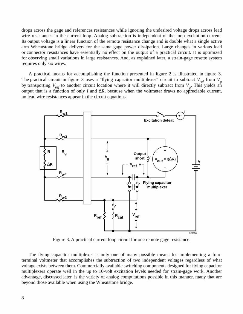
A practical means for accomplishing the function presented in figure 2 is illustrated in figure 3.The practical circuit in figure 3 uses a “flying capacitor multiplexer” circuit to subtract Vref from Vgby transporting Vref to another circuit location where it will directly subtract from Vg. This yields anoutput that is a function of only I and ∆R, because when the voltmeter draws no appreciable current,no lead wire resistances appear in the circuit equations.
Figure 3. A practical current loop circuit for one remote gage resistance.
920650
VrefRcalRref
+
–
Flying capacitor multiplexer
Vout = I(∆R)V
+
–
I
Excitation defeat
Output short
Vref +–
Vg
+
–
Rw1
Rw3
Rg
Rw4
Rw2
R
∆R
The flying capacitor multiplexer is only one of many possible means for implementing a four-terminal voltmeter that accomplishes the subtraction of two independent voltages regardless of whatvoltage exists between them. Commercially available switching components designed for flying capacitormultiplexers operate well in the up to 10-volt excitation levels needed for strain-gage work. Anotheradvantage, discussed later, is the variety of analog computations possible in this manner, many that arebeyond those available when using the Wheatstone bridge.
8
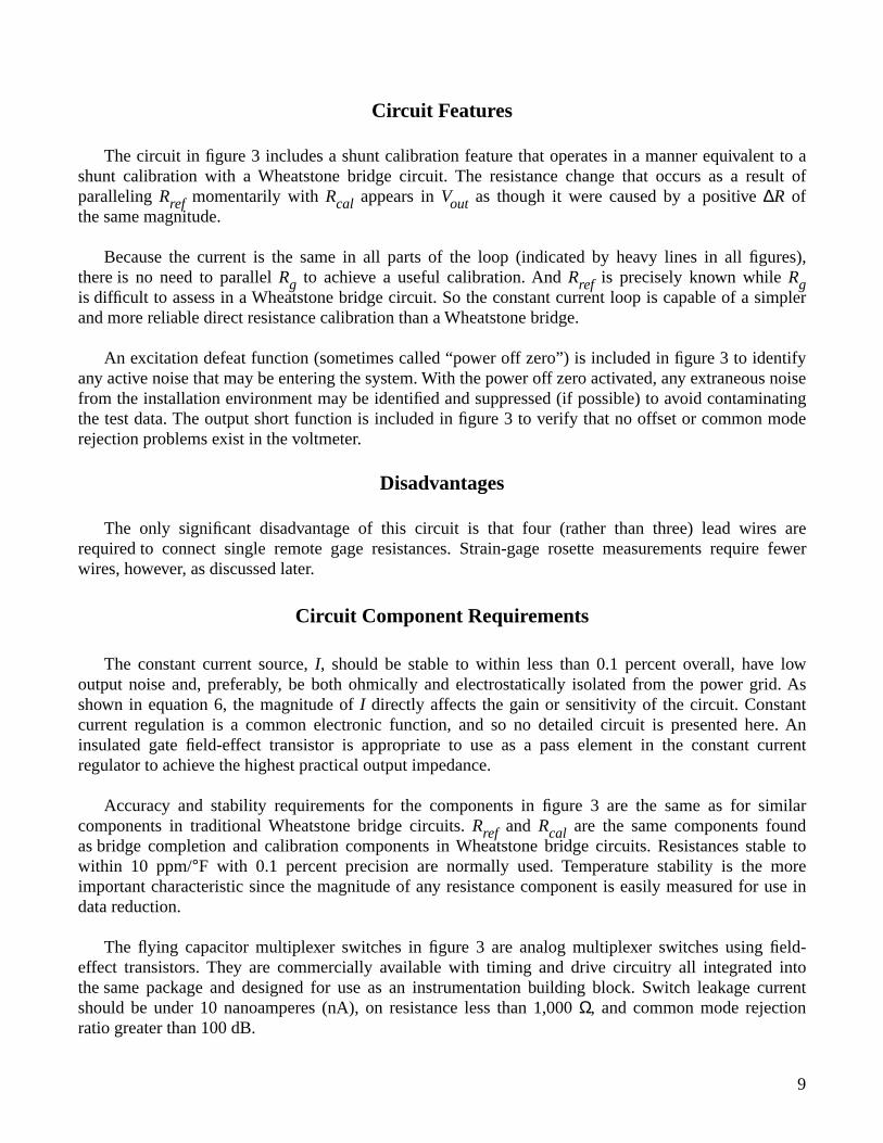
Circuit Features
The circuit in figure 3 includes a shunt calibration feature that operates in a manner equivalent to ashunt calibration with a Wheatstone bridge circuit. The resistance change that occurs as a result ofparalleling Rref momentarily with Rcal appears in Vout as though it were caused by a positive ∆R ofthe same magnitude.
Because the current is the same in all parts of the loop (indicated by heavy lines in all figures),there is no need to parallel Rg to achieve a useful calibration. And Rref is precisely known while Rgis difficult to assess in a Wheatstone bridge circuit. So the constant current loop is capable of a simplerand more reliable direct resistance calibration than a Wheatstone bridge.
An excitation defeat function (sometimes called “power off zero”) is included in figure 3 to identifyany active noise that may be entering the system. With the power off zero activated, any extraneous noisefrom the installation environment may be identified and suppressed (if possible) to avoid contaminatingthe test data. The output short function is included in figure 3 to verify that no offset or common moderejection problems exist in the voltmeter.
Disadvantages
The only significant disadvantage of this circuit is that four (rather than three) lead wires arerequired to connect single remote gage resistances. Strain-gage rosette measurements require fewerwires, however, as discussed later.
Circuit Component Requirements
The constant current source, I, should be stable to within less than 0.1 percent overall, have lowoutput noise and, preferably, be both ohmically and electrostatically isolated from the power grid. Asshown in equation 6, the magnitude of I directly affects the gain or sensitivity of the circuit. Constantcurrent regulation is a common electronic function, and so no detailed circuit is presented here. Aninsulated gate field-effect transistor is appropriate to use as a pass element in the constant currentregulator to achieve the highest practical output impedance.
Accuracy and stability requirements for the components in figure 3 are the same as for similarcomponents in traditional Wheatstone bridge circuits. Rref and Rcal are the same components foundas bridge completion and calibration components in Wheatstone bridge circuits. Resistances stable towithin 10 ppm/°F with 0.1 percent precision are normally used. Temperature stability is the moreimportant characteristic since the magnitude of any resistance component is easily measured for use indata reduction.
The flying capacitor multiplexer switches in figure 3 are analog multiplexer switches using field-effect transistors. They are commercially available with timing and drive circuitry all integrated intothe same package and designed for use as an instrumentation building block. Switch leakage currentshould be under 10 nanoamperes (nA), on resistance less than 1,000 Ω, and common mode rejectionratio greater than 100 dB.
9
The capacitors in the circuit are nominally 1.0 microfarad (µF) metalized polypropylene filmdevices with low dielectric leakage. They are a type commonly used for sample and hold purposes.The magnitude of capacitance does not need to be either precise or stable since their only function is totransfer and store electrical charge with minimal loss. Since the capacitors remain charged to constantlevels in operation, no significant current surges occur in the circuit and the signal-to-noise ratio is high.It is usually not necessary to synchronize the flying capacitor multiplexer with other switching in themeasurement system.
The calibration and output short switches are typically electromechanical switches or relays butfield-effect transistor switches may be used if they have “on” resistances under 1 Ω and leakage currentsunder 10 nA. The calibration switch “on” resistance can be added to Rcal in calculating the responsedue to paralleling Rcal with Rref.
The excitation defeat switch can be either an electromechanical relay or a transistor switch capableof carrying at least 30 mA. Power metal-oxide semiconductor field effect transistors (MOSFETs) having“on” resistances of under 1 Ω are suitable for this purpose. Excitation defeat can also be accomplishedby programming the excitation current to zero.
The upper frequency limit of the circuit in figure 3 will be a function of the bandwidth of theconstant current regulator, the bandwidth of the voltmeter (the voltage drop, Vref, across Rref isconstant), and any electrical energy storage capability along the current loop.
Experimental Results
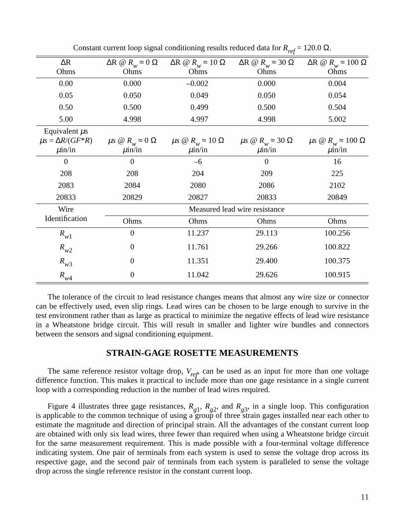
The circuit in figure 3 was used to gather data that demonstrates the sensitivity of its output to ∆Rand its immunity to wide variations in the resistances of its lead wires. The tests involved extensivevariations in both lead wire resistance (from 0 to 100 Ω) and gage resistance ∆R (from 0 to 5 Ω).
The following table summarizes the test results by presenting a limited set of data that cover theentire range of conditions tested. Data were reduced in terms of electrical resistance and microinchesper inch (µin/in) of strain from a 120-Ω strain gage with a gage factor of 2. The ∆R is varied from0 to 5 Ω in decades. The excitation current was 10 mA. The left column lists the input conditionsin resistance change and equivalent microstrain (µs). The four right columns contain reduced datafrom voltage measurements using a bench top digital multimeter with 1.0 µV dc voltage and 1.0 mΩresistance resolution. Offsets in the data set are all with respect to the initial indication with ∆R and allRw values set to zero. The bottom section of the table lists the measured Rw resistances in the variouslead wires to identify the test condition for that column.
The data in the table show that the circuit output is a reliable function of ∆R. Note that, unlikea Wheatstone bridge circuit, the lead wire resistances Rw1 through Rw4 are not identical. While theyappear to be closely matched, in fact the variation in resistance among the four lead wires exceedsthe normal output from a 120-Ω gage resistance’s ∆R of about 0.5 Ω. Such lead wire variations in aWheatstone bridge circuit would render its output indications completely useless. But with the constantcurrent loop circuit, any single lead wire can be varied by 100 Ω or more with insignificant variationin the output indication.
10
The tolerance of the circuit to lead resistance changes means that almost any wire size or connectorcan be effectively used, even slip rings. Lead wires can be chosen to be large enough to survive in thetest environment rather than as large as practical to minimize the negative effects of lead wire resistancein a Wheatstone bridge circuit. This will result in smaller and lighter wire bundles and connectorsbetween the sensors and signal conditioning equipment.
STRAIN-GAGE ROSETTE MEASUREMENTS
The same reference resistor voltage drop, Vref, can be used as an input for more than one voltagedifference function. This makes it practical to include more than one gage resistance in a single currentloop with a corresponding reduction in the number of lead wires required.
Figure 4 illustrates three gage resistances, Rg1, Rg2, and Rg3, in a single loop. This configurationis applicable to the common technique of using a group of three strain gages installed near each other toestimate the magnitude and direction of principal strain. All the advantages of the constant current loopare obtained with only six lead wires, three fewer than required when using a Wheatstone bridge circuitfor the same measurement requirement. This is made possible with a four-terminal voltage differenceindicating system. One pair of terminals from each system is used to sense the voltage drop across itsrespective gage, and the second pair of terminals from each system is paralleled to sense the voltagedrop across the single reference resistor in the constant current loop.
Constant current loop signal conditioning results reduced data for Rref = 120.0 Ω.
∆ROhms
∆R @ Rw ≈ 0 ΩOhms
∆R @ Rw ≈ 10 ΩOhms
∆R @ Rw ≈ 30 ΩOhms
∆R @ Rw ≈ 100 ΩOhms
0.00 0.000 –0.002 0.000 0.004
0.05 0.050 0.049 0.050 0.054
0.50 0.500 0.499 0.500 0.504
5.00 4.998 4.997 4.998 5.002
Equivalent µsµs = ∆R/(GF*R)
µin/inµs @ Rw ≈ 0 Ω
µin/inµs @ Rw ≈ 10 Ω
µin/inµs @ Rw ≈ 30 Ω
µin/inµs @ Rw ≈ 100 Ω
µin/in
0 0 –6 0 16
208 208 204 209 225
2083 2084 2080 2086 2102
20833 20829 20827 20833 20849
WireIdentification
Measured lead wire resistance
Ohms Ohms Ohms Ohms
Rw1 0 11.237 29.113 100.256
Rw2 0 11.761 29.266 100.822
Rw3 0 11.351 29.400 100.375
Rw4 0 11.042 29.626 100.915
11
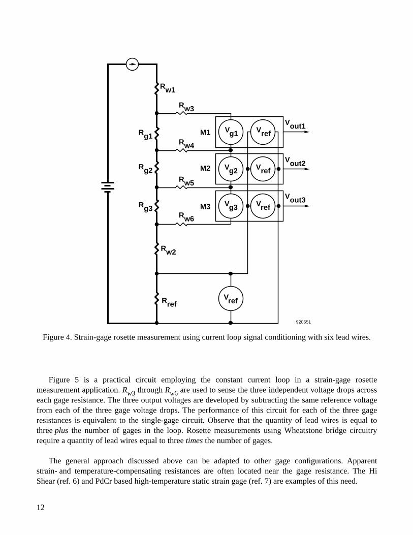
Figure 4. Strain-gage rosette measurement using current loop signal conditioning with six lead wires.
920651
VrefRref
Rw2
Rw6
Rg3
Rg2
Rg1
Rw5
Rw4
Rw3
Rw1
M1
M2
M3
Vout1
Vout2
Vout3Vg3
Vg2
Vg1
Vref
Vref
Vref
Figure 5 is a practical circuit employing the constant current loop in a strain-gage rosettemeasurement application. Rw3 through Rw6 are used to sense the three independent voltage drops acrosseach gage resistance. The three output voltages are developed by subtracting the same reference voltagefrom each of the three gage voltage drops. The performance of this circuit for each of the three gageresistances is equivalent to the single-gage circuit. Observe that the quantity of lead wires is equal tothree plus the number of gages in the loop. Rosette measurements using Wheatstone bridge circuitryrequire a quantity of lead wires equal to three times the number of gages.
The general approach discussed above can be adapted to other gage configurations. Apparentstrain- and temperature-compensating resistances are often located near the gage resistance. The HiShear (ref. 6) and PdCr based high-temperature static strain gage (ref. 7) are examples of this need.
12
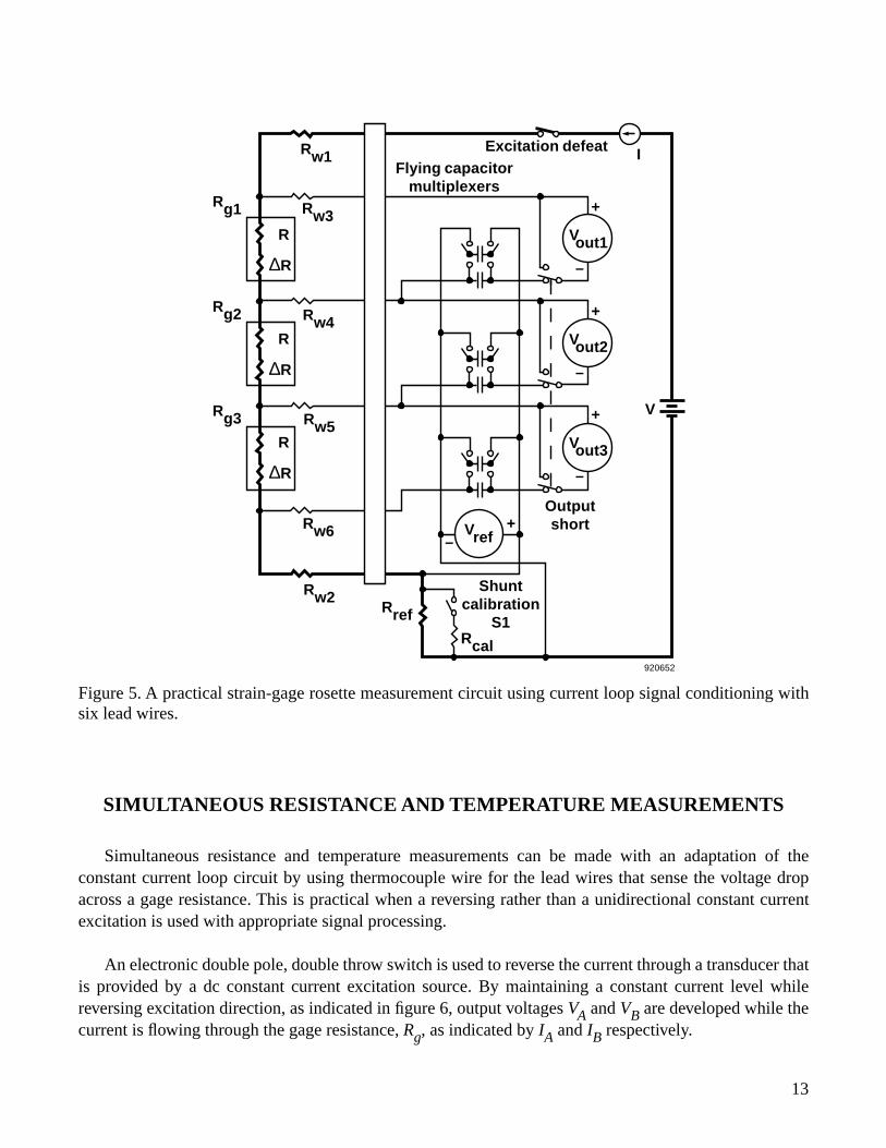
Figure 5. A practical strain-gage rosette measurement circuit using current loop signal conditioning withsix lead wires.
920652
Rref
Shunt calibration
S1Rcal
Output short+
–
+
–
+
–
+
–
V
Vref
Vout3
Vout2
Vout1
Rw2
Rw6
Rw5
Rw4
Rw3
Rw1
Rg1
Rg2
Rg3
R
∆R
R
∆R
R
∆R
IExcitation defeatFlying capacitor
multiplexers
SIMULTANEOUS RESISTANCE AND TEMPERATURE MEASUREMENTS
Simultaneous resistance and temperature measurements can be made with an adaptation of theconstant current loop circuit by using thermocouple wire for the lead wires that sense the voltage dropacross a gage resistance. This is practical when a reversing rather than a unidirectional constant currentexcitation is used with appropriate signal processing.
An electronic double pole, double throw switch is used to reverse the current through a transducer thatis provided by a dc constant current excitation source. By maintaining a constant current level whilereversing excitation direction, as indicated in figure 6, output voltages VA and VB are developed while thecurrent is flowing through the gage resistance, Rg, as indicated by IA and IB respectively.
13
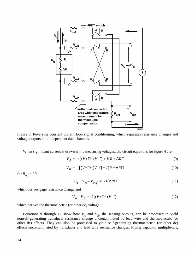
Figure 6. Reversing constant current loop signal conditioning, which separates resistance changes andvoltage outputs into independent data channels.
920653
Isothermal connection area with temperature measurement for thermocouple compensation I
Rref Vref
+
–
BARw2
V–
Rw4
Rw3
R
∆R
Rg
V+
A B
A B
+
–
VA and VB
IA B
IAIB
Rw1
4PDT switch
I
When significant current is drawn while measuring voltages, the circuit equations for figure 4 are
(9)
(10)
for Rref = 2R,
(11)
which derives gage resistance change and
(12)
which derives the thermoelectric (or other dc) voltage.
Equations 9 through 12 show how VA and VB, the sensing outputs, can be processed to yieldnonself-generating transducer resistance change uncontaminated by lead wire and thermoelectric (orother dc) effects. They can also be processed to yield self-generating thermoelectric (or other dc)effects uncontaminated by transducer and lead wire resistance changes. Flying capacitor multiplexers,
V A + V+( ) V–( )+[ ] I R ∆R+( )+=
VB – V+( ) V–( )+[ ] I R ∆R+( )+=
V A VB Vref–+ 2I ∆R( )=
V A VB– 2 V+( ) V–( )+[ ]=
14
synchronized to capture and sum the various signals, have been successfully used to accomplish thearithmetic processing.
In this manner, four lead wires, including a pair of thermocouple wires, provide an outputproportional to ∆R uncontaminated by lead wire resistance and thermoelectric effects. A separate outputis developed that is proportional to the temperature of the thermocouple lead wire attachments to theterminals of the gage resistance. This is accomplished while preserving all the advantages of the directconstant current version except frequency response.
Regardless of the capabilities of the sensors, system frequency response will be limited by samplingtheory to no greater than half the excitation current reversal frequency. In practice, several samples willbe required to demultiplex the output in response to an input change so the practical upper frequencyresponse will be on the order of one-twentieth the excitation reversal frequency.
CONCLUSIONS
A practical signal conditioning circuit for resistance transducers identified as the constant currentloop has been synthesized, analyzed and demonstrated. Theoretical predictions and laboratory resultsagree, demonstrating that the output provides dc frequency response, is unaffected by extremely largevariations in lead wire resistance, and is inherently linear. The sensitivity is double that which aWheatstone bridge delivers for the same power dissipation in the gage resistance.
Fewer and smaller lead wires are needed in multiple transducer installations, such as strain-gagerosettes, than for the Wheatstone bridge. An approach has been described that separates self-generating(such as thermoelectric) and nonself-generating (resistance change) effects into independent datachannels by using alternating constant current excitation for the loop along with appropriate signalprocessing.
Dryden Flight Research FacilityNational Aeronautics and Space AdministrationEdwards, California, October 29, 1992
15
REFERENCES
1. M.M. Lemcoe and Keith Krake, “Dryden Hi-Temperature Strain Measurement SystemsAccomplishments and Future Work,” Paper Number 263.B, NASP Mid Term Technology Review,Monterey, CA, April 21–24, 1992.
2. “NASP Strain Gage Workshop–1991,” NASP Workshop Publication 1010, Proceedings of the FirstNasp Strain Gage Workship sponsored by NASA Lewis Research Center, Cleveland, OH, April 9–10,1991. (Distribution restricted to U.S. government agencies and U.S. government agency contractorsonly. Other requestors should contact the NASP Joint Programs Office, Wright-Patterson AFB, OH.)
3. Wheatstone, Sir Charles, “An Account of Several New Instruments and Processes for Determining theConstants of a Voltaic Circuit,” Philosophical Transactions of the Royal Society of London, vol. 133,1843, pp. 303–329.
4. C.C. Perry and H.R. Lissner, The Strain Gage Primer, McGraw-Hill, Inc., New York, 1962.
5. Barret B. Weeks and William E. Shoemaker, “Tri-Current Transducer Conditioner,” ISA PreprintNumber 9.1-3-65, 1965.
6. “Adverse Environment Weldable Strain Gages,” Product Catalog, Eaton Corp., Troy Michigan,Oct. 1985.
7. J. Lei and W. Williams, “PdCr Based High Temperature Static Strain Gage,” AIAA-90-5236, 1990.
16
REPORT DOCUMENTATION PAGE Form ApprovedOMB No. 0704-0188
Public reporting burden for this collection of information is estimated to average 1 hour per response, including the time for reviewing instructions, searching existing data sources, gathering andmaintaining the data needed, and completing and reviewing the collection of information. Send comments regarding this burden estimate or any other aspect of this collection of information,including suggestions for reducing this burden, to Washington Headquarters Services, Directorate for Information Operations and Reports, 1215 Jefferson Davis Highway, Suite 1204, Arlington,VA 22202-4302, and to the Office of Management and Budget, Paperwork Reduction Project (0704-0188), Washington, DC 20503.
1. AGENCY USE ONLY (Leave blank) 2. REPORT DATE 3. REPORT TYPE AND DATES COVERED
4. TITLE AND SUBTITLE 5. FUNDING NUMBERS
6. AUTHOR(S)
8. PERFORMING ORGANIZATION REPORT NUMBER
7. PERFORMING ORGANIZATION NAME(S) AND ADDRESS(ES)
9. SPONSORING/MONITORING AGENCY NAME(S) AND ADDRESS(ES) 10. SPONSORING/MONITORING AGENCY REPORT NUMBER
11. SUPPLEMENTARY NOTES
12a. DISTRIBUTION/AVAILABILITY STATEMENT 12b. DISTRIBUTION CODE
13. ABSTRACT (Maximum 200 words)
14. SUBJECT TERMS 15. NUMBER OF PAGES
16. PRICE CODE
17. SECURITY CLASSIFICATION OF REPORT
18. SECURITY CLASSIFICATION OF THIS PAGE
19. SECURITY CLASSIFICATION OF ABSTRACT
20. LIMITATION OF ABSTRACT
NSN 7540-01-280-5500 Standard Form 298 (Rev. 2-89)Prescribed by ANSI Std. Z39-18298-102
The Constant Current Loop: A New Paradigm for Resistance Signal Conditioning
WU 505-63-40
Karl F. Anderson
NASA Dryden Flight Research FacilityP.O. Box 273Edwards, California 93523-0273
H-1861
National Aeronautics and Space AdministrationWashington, DC 20546-0001 NASA TM-104260
A practical single constant current loop circuit for the signal conditioning of variable resistance transducers hasbeen synthesized, analyzed, and demonstrated. The strain gage and the resistance temperature device are examplesof variable resistance sensors. Lead wires connect variable resistance sensors to remotely located signalconditioning hardware. The presence of lead wires in the conventional Wheatstone bridge signal conditioningcircuit introduces undesired effects that reduce the quality of the data from the remote sensors. A practical approachis presented for suppressing essentially all lead wire resistance effects while indicating only the change inresistance value. Theoretical predictions supported by laboratory testing confirm the following features of theapproach: (1) dc response; (2) the electrical output is unaffected by extremely large variations in the resistance ofany or all lead wires; (3) the electrical output remains zero for no change in gage resistance; (4) the electrical outputis inherently linear with respect to gage resistance change; (5) the sensitivity is double that of a Wheatstone bridgecircuit; and (6) the same excitation wires can serve multiple independent gages. An adaptation of current loopcircuit is presented that simultaneously provides an output signal voltage directly proportional to transducerresistance change and provides temperature information that is unaffected by transducer and lead wire resistancevariations. These innovations are the subject of NASA patent applications.
Measuring instruments; Strain gages; Temperature sensors; Test equipment; Thermocouples
A03
22
Unclassified Unclassified Unclassified Unlimited
October 1992 NASA Technical Memorandum
Available from the NASA Center for AeroSpace Information, 800 Elkridge Landing Road, Linthicum Heights, MD 21090; (301)621-0390
Unclassified—UnlimitedSubject Category 35