Embed Size (px)
Citation preview
TRANSNET NATIONAL PORTS AUTHORITY
ADDITIONAL BIDVEST TERMINAL TANKS RAIL LINE AT SOUTH DUNES, PORT OF RICHARDS BAY WATER USE LICENSE APPLICATION – CONSTRUCTION METHODOLOGY
1
THE CONSTRUCTION OF AN ADDTIONAL BIDVEST TANK TERMINAL (BTT) RAIL LINE AT SOUTH DUNES, WITHIN THE PORT OF RICHARDS BAY
CONSTRUCTION METHOD STATEMENT
1. INTRODUCTION
The Port of Richards Bay, in its effort to diversify from its main commodity, namely coal, which
was and currently is attracting low tariffs and revenue, embarked on a more intensive
development approach to the South Dunes Precinct as a liquid bulk site in 2008.
As a result, the Port approved a Port Development Framework Plan (PDFP) that earmarked the
South Dunes Precinct for liquid bulk terminals. To realize the envisaged developments at South
Dunes, the Port then submitted a business case in 2008 for the development of services
infrastructure aimed at providing access to South Dunes sites as outlined in the PDFP.
Current Port tenants Bidvest Tank Terminals (BTT) have an environmental authorisation in
place for the construction of two new rail facilities to the east of the current rail servitude. TNPA
has however expressed its need to utilise the outermost of these two already authorised rails
on the east to allow for accessibility to future lease sites.
TNPA is therefore seeking to obtain approval for the construction of an additional line to the
west of the existing rail servitude with the intention of exchanging it with their tenant’s (BTT) line
on the east side, i.e. a like for like swap, enabling TNPA to access future lease areas.
2. RAIL INFRASTRUCTURE DESIGN
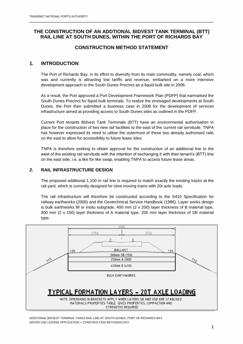
The proposed additional 1,100 m rail line is required to match exactly the existing tracks at the
rail yard, which is currently designed for slow moving trains with 20t axle loads.
The rail infrastructure will therefore be constructed according to the S410 Specification for
railway earthworks (2006) and the Geotechnical Service Handbook (1986). Layer works design
is bulk earthworks fill or insitu subgrade, 400 mm (2 x 200) layer thickness of B material type,
300 mm (2 x 150) layer thickness of A material type, 200 mm layer thickness of SB material
type.
TRANSNET NATIONAL PORTS AUTHORITY
ADDITIONAL BIDVEST TERMINAL TANKS RAIL LINE AT SOUTH DUNES, PORT OF RICHARDS BAY WATER USE LICENSE APPLICATION – CONSTRUCTION METHODOLOGY
2
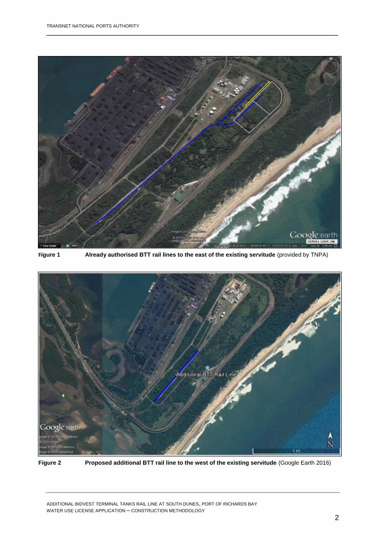
Figure 1 Already authorised BTT rail lines to the east of the existing servitude (provided by TNPA)
Figure 2 Proposed additional BTT rail line to the west of the existing servitude (Google Earth 2016)
TRANSNET NATIONAL PORTS AUTHORITY
ADDITIONAL BIDVEST TERMINAL TANKS RAIL LINE AT SOUTH DUNES, PORT OF RICHARDS BAY WATER USE LICENSE APPLICATION – CONSTRUCTION METHODOLOGY
3
3. RAIL INFRASTRUCTURE CONSTRUCTION METHODOLOGY
The construction of the additional rail line will typically be completed over the following major
stages.
3.1. Clearing and grubbing
The whole area to be occupied on the west side of the existing rail servitude, 16 m x 1,250 m,
will be cleared of vegetation and grubbed. Clearing includes removal and disposal of all trees,
stumps, logs, timber, scrub, vegetation, minor structures, refuse and other material unsuitable
for incorporation in the work.
Grubbing will be carried out to the level of 0.5 m below natural surface or 1.5 m below finished
earthworks level unless otherwise indicated. Holes left after grubbing under the proposed
embankments are to be filled with suitable material and compacted in layers.
3.2. Removal of topsoil and unsuitable material
Topsoil will be removed from the construction footprint and stockpiled clear of the works area to
enable its re-use in landscaping and re-vegetation. Unsuitable material includes topsoil, peat
and other highly organic soils, logs, stumps, perishable material, refuse, stones, material
susceptible to spontaneous combustion, free draining materials susceptible to scouring very
fine sand, silt clay lumps and organic and clay. Such material shall be excavated and disposed
of offsite except for topsoil required for vegetation propagation.
Dispersive soils can be used only in accordance with guidelines provided by a Geotechnical
Engineer. Where unsuitable material exists in excessive depths the advice of a Geotechnical
Engineer or Project Engineer is required.
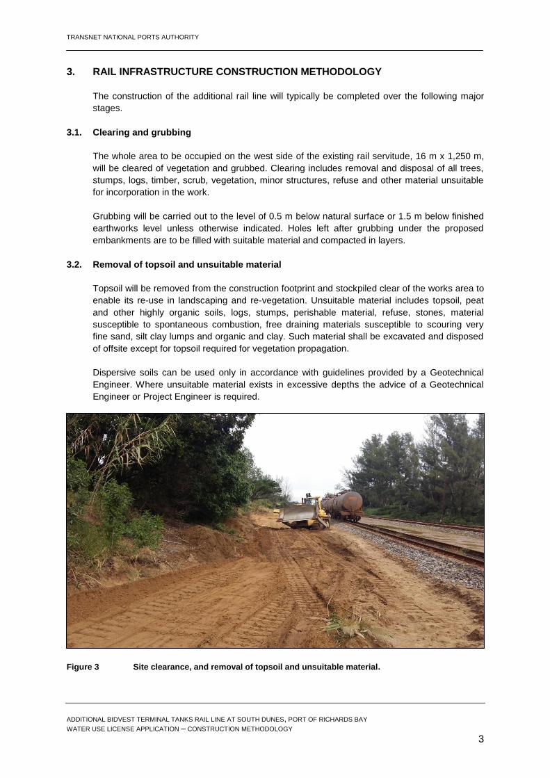
Figure 3 Site clearance, and removal of topsoil and unsuitable material.

TRANSNET NATIONAL PORTS AUTHORITY
ADDITIONAL BIDVEST TERMINAL TANKS RAIL LINE AT SOUTH DUNES, PORT OF RICHARDS BAY WATER USE LICENSE APPLICATION – CONSTRUCTION METHODOLOGY
4
3.3. Excavation for cuttings
Excavation shall be carried out to the lines, levels, dimensions and slopes as per the final
drawings (once issued). The excavated faces shall be neatly trimmed and the top edges of the
cuttings neatly rounded.
Excavation shall be carried out in such a manner as to prevent erosion and unnecessary
destruction to the natural environment, working faces shall be limited to safe heights and
slopes, and the surface shall be drained to avoid ponding and erosion.
Overhanging, loose or unstable material likely to slip will be cut back removed or stabilised.
Batters in cuttings shall be carried around curves in an even and regular manner. Finished
batters shall not have a slope steeper than 1.75:1. Box cut excavation for rail formation will be
to a depth of 250 mm or if otherwise indicated by the project engineer.
Surplus material will be loaded and carted to be stockpiled to reserve the material for future
needs of the Port’s developments (part of the Port’s drive to minimise waste land filling).
3.4. Track construction
3.4.1 Ballast
Ballast is a specific type of rock used for supporting the sleepers and rail track, keeping them in
place while trains run. A ballast machine rides the new tracks and places the ballast over the
sleepers and between the tracks.
Figure 4 Site preparation and earth works and ready for track construction.
TRANSNET NATIONAL PORTS AUTHORITY
ADDITIONAL BIDVEST TERMINAL TANKS RAIL LINE AT SOUTH DUNES, PORT OF RICHARDS BAY WATER USE LICENSE APPLICATION – CONSTRUCTION METHODOLOGY
5
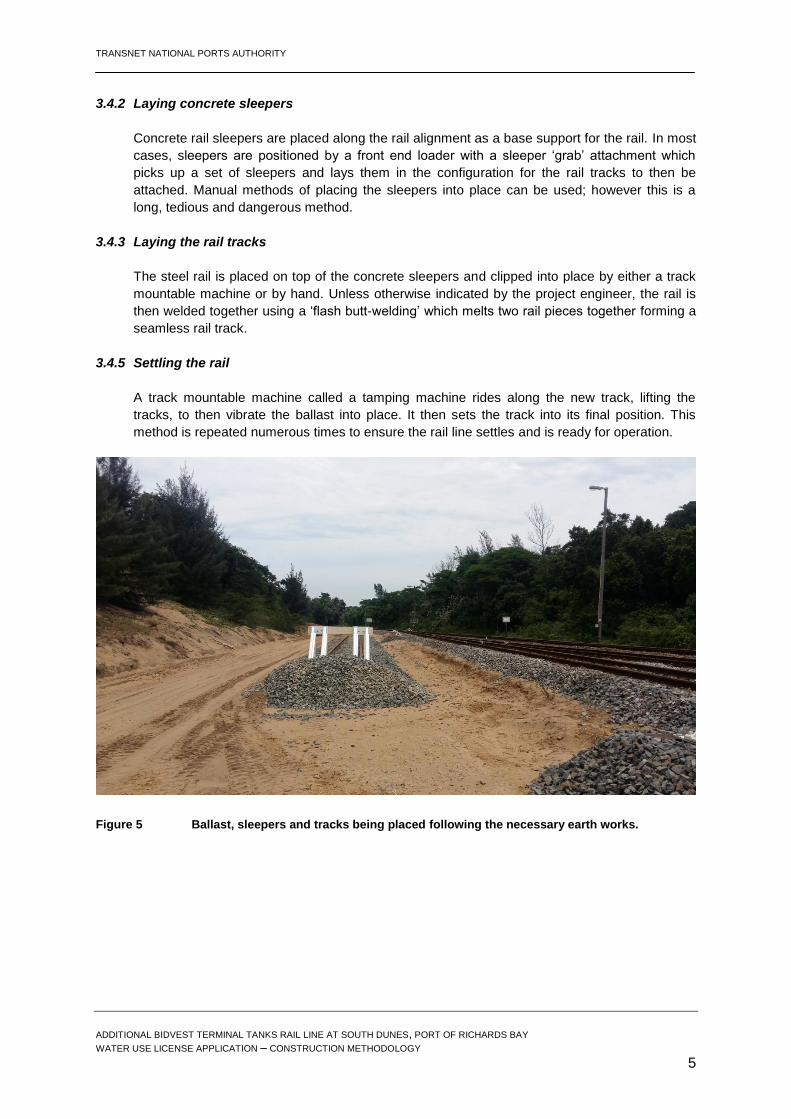
3.4.2 Laying concrete sleepers
Concrete rail sleepers are placed along the rail alignment as a base support for the rail. In most
cases, sleepers are positioned by a front end loader with a sleeper ‘grab’ attachment which
picks up a set of sleepers and lays them in the configuration for the rail tracks to then be
attached. Manual methods of placing the sleepers into place can be used; however this is a
long, tedious and dangerous method.
3.4.3 Laying the rail tracks
The steel rail is placed on top of the concrete sleepers and clipped into place by either a track
mountable machine or by hand. Unless otherwise indicated by the project engineer, the rail is
then welded together using a ‘flash butt-welding’ which melts two rail pieces together forming a
seamless rail track.
3.4.5 Settling the rail
A track mountable machine called a tamping machine rides along the new track, lifting the
tracks, to then vibrate the ballast into place. It then sets the track into its final position. This
method is repeated numerous times to ensure the rail line settles and is ready for operation.
Figure 5 Ballast, sleepers and tracks being placed following the necessary earth works.

TRANSNET NATIONAL PORTS AUTHORITY
ADDITIONAL BIDVEST TERMINAL TANKS RAIL LINE AT SOUTH DUNES, PORT OF RICHARDS BAY WATER USE LICENSE APPLICATION – CONSTRUCTION METHODOLOGY
6
3.4.6 Installing ancillary infrastructure
Any additional or supporting infrastructures such as sign posts or “signalling lights” that are
required are installed along the rail route.
Figure 6 Ancillary works (signage, lighting, etc) installed following completion of the rail