Embed Size (px)
Citation preview

The Containment of Underground NuclearExplosions
October 1989
NTIS order #PB90-156183
Recommended Citation:
U.S. Congress, Office of Technology Assessment, The Containment of Underground NuclearExplosions, OTA-ISC-414 (Washington, DC: U.S. Government Printing Office, October1989),
Library of Congress Catalog Card Number 89-600707
For sale by the Superintendent of DocumentsU.S. Government Printing Office, Washington, DC 20402-9325
(order form can be found in the back of this report)

Foreword
Within weeks after the ending of World War II, plans for the first nuclear test series“Operation Crossroads” were underway. The purpose then, as now, was to develop newweapon systems and to study the effects of nuclear explosions on military equipment. Thedevelopment of the nuclear testing program has been paralleled by public opposition from bothan arms control and an environmental perspective. Much of the criticism is due to the symbolicnature of testing nuclear weapons and from the radiation hazards associated with the earlypractice of testing in the atmosphere. Recently, however, specific concerns have also beenraised about the current underground testing program; namely:
. Are testing practices safe?
. Could an accidental release of radioactive material escape undetected?● Is the public being fully informed of all the dangers emanating from the nuclear testing
program?
These concerns are fueled in part by the secrecy that surrounds the testing program and bypublicized problems at nuclear weapons production facilities.
At the request of the House Committee on Interior and Insular Affairs and Senator OrrinG. Hatch, OTA undertook an assessment of the containment and monitoring practices of thenuclear testing program. This special report reviews the safety of the nuclear testing programand assesses the technical procedures used to test nuclear weapons and ensure that radioactivematerial produced by test explosions remains contained underground. An overall evaluationconsiders the acceptability of the remaining risk and discusses reasons for the lack of publicconfidence.
In the course of this assessment, OTA drew on the experience of many organizations andindividuals. We appreciate the assistance of the U.S. Government agencies and privatecompanies who contributed valuable information, the workshop participants who providedguidance and review, and the many additional reviewers who helped ensure the accuracy andobjectivity of this report.
,..Ill
Workshop 1: ContainmentMonday, Sept. 26,1988
Environmental Research CenterUniversity of Nevada, Las Vegas
Neville G. Cook, ChairDepartment of Material Science and Mineral Engineering
University of California
Frederick N. AppSection LeaderContainment GeophysicsLos Alamos National Laboratory
Norman R. BurkhardContainment Program LeaderLawrence Livermore National Laboratory
Jim CarothersChairmanContainment Evaluation PanelLawrence Livermore National Laboratory
Jack EverndenLawrence Livermore National LaboratoryU.S. Geological Survey
Robert A. FulkersonExecutive DirectorCitizen Alert
Jack W. HouseContainment Program ManagerLos Alamos National Laboratory
Evan JenkinsU.S. Geological Survey
Joseph LaCombChiefNevada Operations OfficeDefense Nuclear Agency
James K. MagruderAssistant Manager for Operations and EngineeringNevada Operations OfficeU.S. Department of Energy
Paul OrkildU.S. Geological Survey
Edward W. PetersonContainment Project DirectorS-CUBED
John StewartDirectorTest Operations DivisionNevada Operations OfficeU.S. Department of Energy
Billy C. HudsonDeputy Containment Program LeaderLawrence Livermore National Laboratory
iv
Workshop 2: MonitoringTuesday, Sept. 27, 1988
Environmental Research CenterUniversity of Nevada, Las Vegas
Melvin W. Carter, ChairNeely Professor Emeritus
Georgia Institute of Technology
Lynn R. AnspaughDivision LeaderEnvironmental Sciences DivisionLawrence Livermore National Laboratory
Bruce ChurchAssistant Manager for Environmental Safety and
HealthNevada Operations OfficeU.S. Department of Energy
Charles F. CostaDirectorNuclear Radiation Assessment DivisionUnited States Environmental Protection Agency
Donald R. ElleChief, Technical Projects BranchHealth Physics and Environmental DivisionNevada Operations OfficeU.S. Department of Energy
Bernd FrankeIFEU
Robert A. FulkersonExecutive DirectorCitizen Alert
Michael A. MarelliChief, Health Protection BranchHealth Physics and Environmental DivisionNevada Operations OfficeU.S. Department of Energy
Darryl RandersonWeather ServiceNuclear Office

OTA Project Staff-The Containment of Underground Nuclear Explosions
Lionel S. Johns, Assistant Director, OTAEnergy, Materials, and International Security Division
Peter Sharfman, International Security and Commerce Program Manager*
Alan Shaw, International Security and Commerce Program Manager**
Gregory E. van der Vink, Project Director
Administrative Staff
Jannie Horne (through November 1988)
Marie C. Parker (through April 1989)
Jackie Robinson
Louise Staley
“Through February 1989.
● *From March 1989.
vi

Acknowledgments
OTA gratefully acknowledges the valuable contributions made by the following:
Lynn R. AnspaughLawrence Livermore National LaboratoryFrederick N. AppLos Alamos National LaboratoryNick AquilinaU.S. Department of EnergyCharles ArchambeauCIRES, University of Colorado, BoulderStuart C. BlackU.S. Environmental Protection AgencyCarter BroylesSandia National LaboratoryNorman R. BurkhardLawrence Livermore National LaboratoryJohn H. CampbellU.S. Department of EnergyJim CarothersLawrence Livermore National LaboratoryMelvin W. CarterInternational Radiation Protection ConsultantBruce ChurchU.S. Department of EnergyNeville G. CookUniversity of California, BerkeleyCharles F. CostaU.S. Environmental Protection AgencyJeff DuncanOffice of Congressman Edward J. MarkeyDonald R. ElleU.S. Department of EnergyGerald L. EpsteinJohn F. Kennedy School of Government, Harvard UniversityJack EverndenU.S. Geological SurveyAnthony FainbergOffice of Technology Assessment, U.S. CongressPete FitzsimmonsU.S. Department of EnergyJanet FoggU.S. Department of EnergyBernd FrankeIFEURobert A. FulkersonCitizen AlertLarry GabrielDefense Nuclear Agency
David GrahamMoore College of ArtJack W. HouseLos Alamos National LaboratoryBilly C. HudsonLawrence Livermore National LaboratoryEvan JenkinsU.S. Geological SurveyGerald W. JohnsonUniversity of CaliforniaJoseph W. LaCombDefense Nuclear AgencyJames K. MagruderU.S. Department of EnergyMichael A. MarelliU.S. Department of EnergyLTC Samuel D. McKinneyDefense Nuclear AgencyDavid N. McNelisUniversity of Las Vegas, NevadaPaul OrkildLawrence Livermore National LaboratoryEdward W. PetersonS-CUBEDDorothy F. PopeDefense Nuclear AgencyDarryl RandersonWeather Service, Nuclear OfficeKaren RandolphU.S. Department of EnergyR.L. RhodesDiebold, Inc.Patrick RoweREECoRobert ShirkeyDefense Nuclear AgencyJohn O. StewartU.S. Department of EnergyRobert TitusWeather Service, Nuclear OfficeDean R. TownsendFenix & Scission, Inc.Chris L. WestU.S. Department of EnergyBarbara YoersU.S. Department of Energy
NOTE: OTA appreciates and is grateful for the valuable assistance and thoughtful critiques provided by the contributors. Thecontributors do not, however, necessarily approve, disapprove, or endorse this report. OTA assumes full responsibility for thereport and the accuracy of its contents. Vil

PageChapter 1. Executive Summary . . . . . . . . . . . . . . . . . . . . . . . . . . . . . . . . . . . . . . . . . . . . . . . . . . . . . . . . . .
Chapter 2. The Nuclear Testing Program . . . . . . . . . . . . . . . . . . . . . . . . . . . . . . . . . . . . . . . . . . . . . . . . .
Chapter 3. Containing Underground Nuclear Explosions . . . . . . . . . . . . . . . . . . . . . . . . . . . . . . . . . . .
Chapter 4. Monitoring Accidental Radiation Releases. . . . . . . . . . . . . . . . . . . . . . . . . . . . . . . . . . . . . .
3
11
31
59

Chapter 1
Executive Summary

CONTENTSPage
INTRODUCTION . . . . . . . . . . . . . . . . . . . . . . . . . . . . . . . . . . . . . . . . . . . . . . . . . . . . . . . . . . . . . . . . . . 3HOW SAFE IS SAFE ENOUGH? . . . . . . . . . . . . . . . . . . . . . . . . . . . . . . . . . . . . . . . . . . . . . . . . . . . 3HOW SAFE HAS IT BEEN? . . . . . . . . . . . . . . . . . . . . . . . . . . . . . . . . . . . . . . . . . . . . . . . . . . . . . . . . 3SPECIFIC CONCERNS . . . . . . . . . . . . . . . . . . . . . . . . . . . . . . . . . . . . . . . . . . . . . . . . . . . . . . . . . . . 5OVERALL EVALUATION . . . . . . . . . . . . . . . . . . . . . . . . . . . . . . . . . . . . . . . . . . . . . . . . . . . . . . . . .6
TableTable Pagel-1. Releases From Underground Tests . . . . . . . . . . . . . . . . . . . . . . . . . . . . . . . . . . . . . . . . . . . . . . 4
Chapter 1
Executive Summary
The chances of an accidental release of radioactive material have been made as remote as possible.Public concerns about safety are fueled by concerns about the testing program in general and
exacerbated by the government’s policy of not announcing all tests.
INTRODUCTIONDuring a nuclear explosion, billions of atoms
release their energy within a millionth of asecond, pressures reach several million poundsper square inch, and temperatures are as high asone-million degrees centigrade. A variety ofradioactive elements are produced depending onthe design of the explosive device and thecontribution of fission and fusion to the explo-sion. The half-lives of the elements producedrange from less than a second to more than amillion years.
Each year over a dozen nuclear weapons aredetonated underground at the Nevada Test Site.l
The tests are used to develop new nuclearweapons and to assess the effects of nuclearexplosions on military systems and other hard-ware. Each test is designed to prevent the releaseof radioactive material. The objective of eachtest is to obtain the desired experimental infor-mation and yet successfully contain the explo-sion underground (i.e., prevent radioactive ma-terial from reaching the atmosphere).
HOW SAFE IS SAFE ENOUGH?Deciding whether the testing program is safe
requires a judgment of how safe is safe enough.The subjective nature of this judgment isillustrated through the decision-making processof the Containment Evaluation Panel (CEP)which reviews and assesses the containment ofeach test.2 The panel evaluates the probability ofcontainment using the terms "high confidence,"‘‘adequate degree of confidence, ’ and ‘‘some
doubt. ” But the Containment Evaluation Panelhas no guidelines that attempt to quantify ordescribe in probabilistic terms what constitutesfor example, an “adequate degree of confi-dence." Obviously, there can never be 100percent confidence that a test will not releaseradioactive material. Whether ‘‘adequate confi-dence” translates into a chance of 1 in 100, 1 in1,000, or 1 in 1,000,000, requires a decisionabout what is an acceptable level of risk. In turn,decisions of acceptable level of risk can only bemade by weighing the costs of an unintentionalrelease against the benefits of testing. Conse-quently, those who feel that testing is importantfor our national security will accept greater risk,and those who oppose nuclear testing will findeven small risks unacceptable.
Establishing an acceptable level of risk isdifficult, not only because of the value judg-ments associated with nuclear testing, but alsobecause the risk is not seen as voluntary by thoseoutside the testing program. A public thatreadily accepts the risks associated with volun-tary activities—such as skydiving or smoking—may still consider the much lower risks associ-ated with nuclear testing unacceptable.
HOW SAFE HAS IT BEEN?Some insight into the safety of the nuclear
testing program can be obtained by reviewingthe containment record. Releases of radioactivematerial are categorized with terms that describeboth the volume of material released and theconditions of the release:
s
l~ently, ~1 U,S. nuclew test explosions are conduct~ at the Nevada lkst Site.
zfie Conttimen[ Evaluation pmel is a group of representa[lves from v~ious la~ratories and technical consulting orgamzations who evaluate theproposed containment plan for each test without regard to cost or other outside considerations (see ch, 2 for a complete di.scusslon).
-3–
4 ● Containment of Underground Nuclear Explosions
Containment Failures: Containment fail-ures are unintentional releases of radioactivematerial to the atmosphere due to a failure of thecontainment system. They are termed “vent-ings, “ if they are prompt, massive releases; or“seeps,” if they are slow, small releases thatoccur soon after the test.
Late-Time Seeps: Late-time seeps are smallreleases that occur days or weeks after a testwhen gases diffuse through pore spaces of theoverlying rock and are drawn to the surface bydecreases in atmospheric pressure.
Controlled Tunnel Purging: A controlledtunnel purging is an intentional release to alloweither recovery of experimental data and equip-ment or reuse of part of the tunnel system.
Operational Release: Operational releasesare small, consequential releases that occurwhen core or gas samples are collected, or whenthe drill-back hole is sealed.
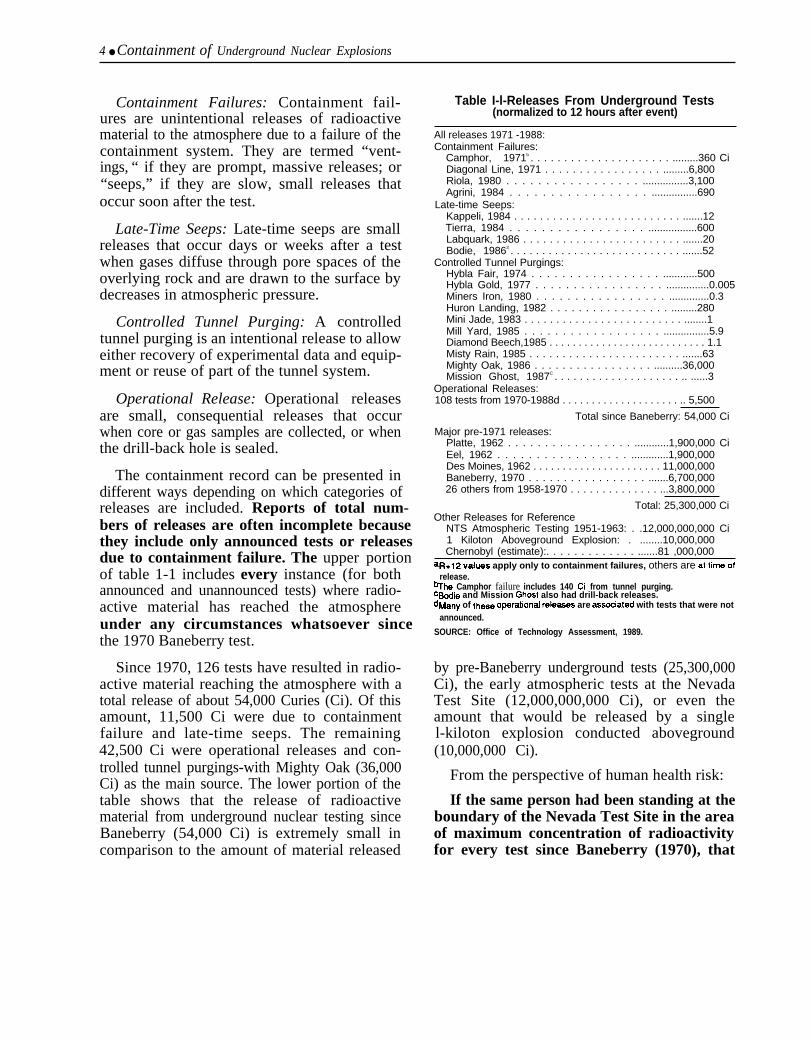
The containment record can be presented indifferent ways depending on which categories ofreleases are included. Reports of total num-bers of releases are often incomplete becausethey include only announced tests or releasesdue to containment failure. The upper portionof table 1-1 includes every instance (for bothannounced and unannounced tests) where radio-active material has reached the atmosphereunder any circumstances whatsoever sincethe 1970 Baneberry test.
Since 1970, 126 tests have resulted in radio-active material reaching the atmosphere with atotal release of about 54,000 Curies (Ci). Of thisamount, 11,500 Ci were due to containmentfailure and late-time seeps. The remaining42,500 Ci were operational releases and con-trolled tunnel purgings-with Mighty Oak (36,000Ci) as the main source. The lower portion of thetable shows that the release of radioactivematerial from underground nuclear testing sinceBaneberry (54,000 Ci) is extremely small incomparison to the amount of material released
Table I-l-Releases From Underground Tests(normalized to 12 hours after event)
All releases 1971 -1988:Containment Failures:
Camphor, 1971b . . . . . . . . . . . . . . . . . . . . . .........360 CiDiagonal Line, 1971 . . . . . . . . . . . . . . . . . .........6,800Riola, 1980 . . . . . . . . . . . . . . . . . ................3,100Agrini, 1984 . . . . . . . . . . . . . . . . . ................690
Late-time Seeps:Kappeli, 1984 . . . . . . . . . . . . . . . . . . . . . . . . . . .......12Tierra, 1984 . . . . . . . . . . . . . . . . . .................600Labquark, 1986 . . . . . . . . . . . . . . . . . . . . . . . . .......20Bodie, 19863 . . . . . . . . . . . . . . . . . . . . . . . . . . . .......52
Controlled Tunnel Purgings:Hybla Fair, 1974 . . . . . . . . . . . . . . . . . ............500Hybla Gold, 1977 . . . . . . . . . . . . . . . . . ...............0.005Miners Iron, 1980 . . . . . . . . . . . . . . . . . ..............0.3Huron Landing, 1982 . . . . . . . . . . . . . . . . . .........280Mini Jade, 1983 . . . . . . . . . . . . . . . . . . . . . . . . . ........1Mill Yard, 1985 . . . . . . . . . . . . . . . . . . ................5.9Diamond Beech,1985 . . . . . . . . . . . . . . . . . . . . . . . . . . . 1.1Misty Rain, 1985 . . . . . . . . . . . . . . . . . . . . . . . .......63Mighty Oak, 1986 . . . . . . . . . . . . . . . . . ..........36,000Mission Ghost, 1987C . . . . . . . . . . . . . . . . . . . . .. ......3
Operational Releases:108 tests from 1970-1988d . . . . . . . . . . . . . . . . . . . . .. 5,500
Total since Baneberry: 54,000 Ci
Major pre-1971 releases:Platte, 1962 . . . . . . . . . . . . . . . . . ............1,900,000 CiEel, 1962 . . . . . . . . . . . . . . . . . .............1,900,000Des Moines, 1962 . . . . . . . . . . . . . . . . . . . . . . 11,000,000Baneberry, 1970 . . . . . . . . . . . . . . . . . .......6,700,00026 others from 1958-1970 . . . . . . . . . . . . . . ...3,800,000
Total: 25,300,000 CiOther Releases for Reference
NTS Atmospheric Testing 1951-1963: . .12,000,000,000 Ci1 Kiloton Aboveground Explosion: . ........10,000,000Chernobyl (estimate):. . . . . . . . . . . . . .......81 ,000,000
aR+12 values apply only to containment failures, others are at tlfne Ofrelease.
%he Camphor failure includes 140 Ci from tunnel purging.c~ie and Mission Ghost also had drill-back releases.dMany of the= operational rele~s are assoaated with tests that were not
announced.
SOURCE: Office of Technology Assessment, 1989.
by pre-Baneberry underground tests (25,300,000Ci), the early atmospheric tests at the NevadaTest Site (12,000,000,000 Ci), or even theamount that would be released by a singlel-kiloton explosion conducted aboveground(10,000,000 Ci).
From the perspective of human health risk:
If the same person had been standing at theboundary of the Nevada Test Site in the areaof maximum concentration of radioactivityfor every test since Baneberry (1970), that
Chapter 1---Executive Summary ● 5
person’s total exposure would be equivalentto 32 extra minutes of normal backgroundexposure (or the equivalent of 1/1000 of asingle chest x-ray).
A worst-case scenario for a catastrophicaccident at the test site would be the prompt,massive venting of a 150-kiloton test (the largestallowed under the 1974 Threshold Test BanTreaty). The release would be in the range of 1to 10 percent of the total radiation generated bythe explosion (compared to 6 percent releasedby the Baneberry test or an estimated 10 percentthat would be released by a test conducted in ahole open to the surface). Such an accidentwould be comparable to a 15-kiloton above--ground test, and would release approximately150,000,000 Ci. Although such an accidentwould be considered a major catastrophe today,during the early years at the Nevada Test Site 25aboveground tests had individual yields equalto or greater than 15 kilotons.
SPECIFIC CONCERNSRecently, several specific concerns about the
safety of the nuclear testing program havearisen, namely:3
1. Does the fracturing of rock at Rainier Mesapose a danger?
The unexpected formation of a surface col-lapse crater during the 1984 Midas Myth testfocused concern about the safety of testing inRainier Mesa. The concern was heightened bythe observation of ground cracks at the top of theMesa and by seismic measurements indicatinga loss of rock strength out to distances greaterthan the depth of burial of the nuclear device.The specific issue is whether the repeated testingin Rainier Mesa had fractured large volumes ofrock creating a “tired mountain’ that no longerhad the strength to successfully contain future
underground tests. The inference that testing inRainier Mesa poses a high level of risk impliesthat conditions for conducting a test on Rainierare more dangerous than conditions for conduct-ing a test on Yucca Flat.4 But, in fact, tests inRainier Mesa are buried deeper and spacedfurther apart than comparable tests on YuccaFlat.5 Furthermore, drill samples show no evi-dence of any permanent decrease in rockstrength at distances greater than two cavityradii from the perimeter of the cavity formed bythe explosion. The large distance of decreasedrock strength seen in the seismic measurementsis almost certainly due to the momentaryopening of pre-existing cracks during passage ofthe shock wave. Most fractures on the top of themesa are due to surface span and do not extenddown to the region of the test. Furthermore, onlyminimal rock strength is required for contain-ment. Therefore, none of the conditions oftesting in Rainier Mesa—burial depth, sepa-ration distance, or material strength—implythat leakage to the surface is more likely fora tunnel test on Rainier Mesa than for avertical drill hole test on Yucca Flat.
2. Could an accidental release of radioactivematerial go undetected?
A comprehensive system for detecting radio-active material is formed by the combination of:
. the monitoring system deployed for eachtest;
. the onsite monitoring system run by theDepartment of Energy (DOE) and;
. the offsite monitoring system, run byEnvironmental Protection Agency (EPA),including the community monitoring sta-tions.
There is essentially no possibility that asignificant release of radioactive material
3W(~l~ an~ysis of tiese concerns is included in chs. 3 and 4.
4A~~oximaIely ~ ~rcent of ~] nuclew test explosions are vertical drill hole tests conducted on Yucca Hal. SW ch. 2 for an exPl~ation of thevarious types of tests,
s~e ~ea~r dep~ of burial is due to convenience. It is easier to mine tLUtIMk ]OWW h the Mesa.
6 ● Containment of Underground Nuclear Explosions
from an underground test could go unde-tected.
3. Are we running out of room to test at theTest Site?
Efforts to conserve space for testing inRainier Mesa have created the impression thatthere is a‘ ‘real estate problem” at the test site.6
The concern is that a shortage of space wouldresult in unsafe testing practices. Although it istrue that space is now used economically topreserve the most convenient locations, otherless convenient locations are available withinthe test site. Suitable areas within the test siteoffer enough space to continue testing atpresent rates for several more decades.
4. Do any unannounced tests release radioac-tive material?
A test will be preannounced in the afternoon2 days before the test if it is determined that themaximum possible yield of the explosion is suchthat it could result in perceptible ground motionin Las Vegas. An announcement will be madeafter a test if there is a prompt release ofradioactive material, or if any late-time releaseresults in radioactivity being detected off the testsite. The Environmental Protection Agency isdependent on the Department of Energy fornotification of any late-time releases within theboundaries of the test site. However, if EPA isnot notified, the release will still be detected byEPA’s monitoring system once radioactive ma-terial reaches outside the test site. If it is judgedthat a late-time release of radioactive mate-rial will not be detected outside the bounda-ries of the test site, the test may (and oftendoes) remain unannounced.
OVERALL EVALUATIONEvery nuclear test is designed to be contained
and is reviewed for containment.7 In each step ofthe test procedure there is built-in redundancy
and conservatism. Every attempt is made tokeep the chance of containment failure asremote as possible. This conservatism andredundancy is essential, however; because nomatter how perfect the process may be, itoperates in an imperfect setting. For each test,the containment analysis is based on samples,estimates, and models that can only simplify and(at best) approximate the real complexities ofthe Earth. As a result, predictions about contain-ment depend largely on judgments developedfrom past experience. Most of what is known tocause problems--carbonate material, water,faults, scarps, clays, etc.—was learned throughexperience. To withstand the consequences of apossible surprise, redundancy and conservatismis a requirement not an extravagance. Conse-quently, all efforts undertaken to ensure a safetesting program are necessary, and must con-tinue to be vigorously pursued.
The question of whether the testing programis ‘‘safe enough’ will ultimately remain a valuejudgment that weighs the importance of testingagainst the risk to health and environment. Inthis sense, concern about safety will continue,largely fueled by concern about the nucleartesting program itself. However, given thecontinuance of testing and the acceptance of theassociated environmental damage, the questionof ‘adequate safety’ becomes replaced with theless subjective question of whether any im-provements can be made to reduce the chancesof an accidental release. In this regard, no areasfor improvement have been identified. This isnot to say that future improvements will not bemade as experience increases, but only thatessentially all suggestions that increase thesafety margin have been implemented. Thesafeguards built into each test make thechances of an accidental release of radioac-tive material as remote as possible.
6SW for ex~ple: William J. Broad, “Bomb l&Is: Txhnology Advances Against Backdrop of Wide Debate,” New York Times, Apr. 15, 1986,pp. C1-C3.
7SW Ch. 3 for a de[ajl~ accounting of the review process.

Chapter 1—Executive Summary ● 7
The acceptability of the remaining risk willdepend on public confidence in the nucleartesting program. This confidence currently suf-fers from a lack of confidence in the Departmentof Energy emanating from problems at nuclearweapons production facilities and from radia-tion hazards associated with the past atmos-pheric testing program. In the case of the presentunderground nuclear testing program, this mis-trust is exacerbated by DOE’s reluctance todisclose information concerning the testingprogram, and by the knowledge that not all testsreleasing radioactive material to the atmosphere(whatever the amount or circumstances) areannounced. As the secrecy associated with thetesting program is largely ineffective in prevent-ing the dissemination of information concerning
the occurrence of tests, the justification for suchsecrecy is questionable.8
The benefits of public dissemination of informa-tion have been successfully demonstrated by theEPA in the area of radiation monitoring. Openlyavailable community monitoring stations allowresidents near the test site to independentlyverify information released by the government,thereby providing reassurance to the communityat large. In a similar manner, public concernover the testing program could be greatlymitigated if a policy were adopted wherebyall tests are announced, or at least all teststhat release radioactive material to the atmos-phere (whatever the conditions) are an-nounced.
8SCC for Cxmple: Rdey R. Ge~t “Nevada RX Site’s dirty little secrets, ” Bulletin of the Atomic Scientists, April 1989, pp. 35-38,

Chapter 2
The Nuclear Testing Program

CONTENTSPage
INTRODUCTION . . . . . . . . . . . . . . . . . . . . . . . . . . . . . . . . . . . . . . . . . . . . . . . . . . . . . . . . . . . . . . . . . 11THE HISTORY OF NUCLEAR TESTING . . . . . . . . . . . . . . . . . . . . . . . . . . . . . . . . . . . . . . . . . 11LIMITS ON NUCLEAR TESTING . . . . . . . . . . . . . . . . . . . . . . . . . . . . . . . . . . . . . . . . . . . . . . . . 14OTHER LOCATIONS OF NUCLEAR TESTS . . . . . . . . . . . . . . . . . . . . . . . . . . . . . . . . . . . . . . 15THE NEVADA TEST SITE . . . . . . . . . . . . . . . . . . . . . . . . . . . . . . . . . . . . . . . . . . . . . . . . . . . . . . . 15TYPES OF NUCLEAR TESTS . . . . . . . . . . . . . . . . . . . . . . . . . . . . . . . . . . . . . . . . . . . . . . . . . . . 18ANNOUNCEMENT OF NUCLEAR TESTS . . . . . . . . . . . . . . . . . . . . . . . . . . . . . . . . . . . . . . . 20DETONATION AUTHORITY AND PROCEDURE . . . . . . . . . . . . . . . . . . . . . . . . . . . . . . . . 22
FiguresFigure Page2-1. U.S Nuclear Testing . . . . . . . . . . . . . . . . . . . . . . . . . . . . . . . . . . . . . . . . . . . . . . . . . . . . . . . . . . 132-2. Nevada Test Site . . . . . . . . . . . . . . . . . . . . . . . . . . . . . . . . . . . . . . . . . . . . . . . . . . . . . . . . . . . . . . 162-3. Drill-Back Operation . . . . . . . . . . . . . . . . . . . . . . . . . . . . . . . . . . . . . . . . . . . . . . . . . . . . . . . . . . 192-4. Locations of Tunnel Tests in Rainier and Aqueduct Mesas . . . . . . . . . . . . . . . . . . . . . . . 21

Chapter 2
The Nuclear Testing Program
The nuclear testing program has played a major role in developing new weapon systems anddetermining the effects of nuclear explosions.
INTRODUCTIONIn the past four decades, nuclear weapons have
evolved into highly sophisticated and specializeddevices. Throughout this evolution, the nucleartesting program has played a major role in develop-ing new weapon systems and determining the effectsof nuclear explosions.
THE HISTORY OF NUCLEARTESTING
On July 16, 1945 the world’s first nuclear bomb(code named “Trinity”) was detonated atop a100-foot steel tower at the Alamogordo BombingRange, 55 miles northwest of Alamogordo, NewMexico. l The explosion had a yield of 21 kilotons(kts), the explosive energy equal to approximately21,000 tons of TNT.2 The following month, Ameri-can planes dropped two atomic bombs (’‘LittleBoy,’ ‘ 13 kilotons; ‘‘Fat Man, ” 23 kilotons) on theJapanese cities of Hiroshima and Nagasaki, endingWorld War II and beginning the age of nuclearweapons. 3
Within weeks after the bombing of Hiroshima andNagasaki, plans were underway to study the effectsof nuclear weapons and explore further designpossibilities. A subcommittee of the Joint Chiefs ofStaff was created, on November 10, 1945, to arrangethe first series of nuclear test explosions. PresidentTruman approved the plan on January 10, 1946. TheBikini Atoll was selected as the test site and theBikinians were relocated to the nearby uninhabited
Rongerik Atoll. Two tests (“Able” and “Baker*’)were detonated on Bikini in June and July of 1946 aspart of “Operation Crossroads,” a series designed tostudy the effects of nuclear weapons on ships,equipment, and material.4 The Bikini Atoll, how-ever, was found to be too small to accommodatesupport facilities for the next test series and so“Operation Sandstone” was conducted on thenearby Enewetak Atoll. The tests of OperationSandstone (“ X-ray,” “ Yoke,” and “Zebra’ wereproof tests for new bomb designs.
As plans developed to expand the nuclear arsenal,the expense, security, and logistical problems oftesting in the Pacific became burdensome. Attentionturned toward establishing a test site within thecontinental United States. The Nevada Test Site waschosen in December 1950 by President Truman as acontinental proving ground for testing nuclear weap-ons. A month later, the first test-code named“Able’ ’-was conducted using a device droppedfrom a B-50 bomber over Frenchman Flat as part ofa five-test series called “Operation Ranger. ’ Thefive tests were completed within 11 days at what wasthen called the ‘‘Nevada Proving Ground. "
Although the Nevada Test Site was fully opera-tional by 1951, the Pacific continued to be used as atest site for developing thermonuclear weapons (alsocalled hydrogen or fusion bombs), On October 31,1952, the United States exploded the first hydrogen(fusion) device on Enewetak Atoll.5 The test, codenamed “Mike,’ had an explosive yield of 10,400kilotons-over 200 times the largest previous test.
I The A]~ogordo Bombing Range is now the White Sands Missile Range.2A kiloton (kl) was o~~n~]y defined as the explosive equivalent of 1,~ tons of TNT. This dcfitition, however, was found 10 bC Imprecise for IWO
reasons. First, there is some variation in the experimental and theoretical vatues of the explosive energy released by TNT (although [hc majority of valueslie in the range from 900 to 1,100 calories per gram). Second, the term kiloton coutd refer to a short kiloton (2xl@ pounds), a metric kiloton (2.205X 1(Y’pounds), or a long kiloton (2.24x I@’ pounds). II was agreed, therefore, during the Manhattan Project that the term “kiloton’ would refer to the rclcawof 101 ~ ( 1 ,000,000,000,000) caloncs of explosive energy.
JJohn Malik, ‘‘The Yields of the Hiroshima and Nagasaki Nuclear Explosions, ’ l-m Alamos National Laboratory repor[ LA-8819, 1985.dThc ~tiget ~onslsted of a fleet of over 90 vc~wls aswmbled in [hc Bikini Lagoon including [hrcc captured German and Japanese ships; SUrplUS U.S.
cruisers, destroyers, and submarines; and amphlbmus craft.~The first test of ~ actual hydrogen bomb (rather [han a device located on the sUrfaCe) wa.. ‘ ‘Cherokee which was dropped from a plane over Bikml
Atoll on May 20, 1956. Extenslvc preparations were made for the test that included the consuuctlon of artificial islands 10 house measuring cquipmcnlThe elaborate experiments required that the bomb be dropped in a precise location in space. To accomplish this, the Stra[eglc Air Command held acompetition for bombing accuracy. Although the winner hit the correct point in every practice run, during the test the bomb was dropped 4 miles off-target.
-11-

12 ● The Containment of Underground Nuclear Explosions
The test was followed 2 weeks later by the 500kiloton explosion “King,” the largest fission weaponever tested.
At the Nevada Test Site, low-yield fission devicescontinued to be tested. Tests were conducted withnuclear bombs dropped from planes, shot fromcannons, placed on top of towers, and suspendedfrom balloons. The tests were designed both todevelop new weapons and to learn the effects ofnuclear explosions on civilian and military struc-tures. Some tests were conducted in conjunctionwith military exercises to prepare soldiers for whatwas then termed “the atomic battlefield. ”
In the Pacific, the next tests of thermonuclear(hydrogen) bombs were conducted under “Opera-tion Castle,’ a series of six tests detonated on theBikini Atoll in 1954. The first test, “Bravo,” wasexpected to have a yield of about 6,000 kilotons. Theactual yield, however, was 15,000 kilotons-overtwice what was expected.6 The radioactive falloutcovered an area larger than anticipated and becauseof a faulty weather prediction, the fallout pattern wasmore easterly than expected. A Japanese fishingboat, which had accidentally wandered into therestricted zone without being detected by the TaskForce, was showered with fallout. When the fishingboat docked in Japan, 23 crew members hadradiation sickness. The radio operator died ofinfectious hepatitis, probably because of the largenumber of required blood transfusions.7 The faultyfallout prediction also led to the overexposure of theinhabitants of two of the Marshall Islands 100 milesto the East. In a similar though less severe accident,radioactive rain from a Soviet thermonuclear test fellon Japan.* These accidents began to focus world-wide attention on the increased level of nucleartesting and the dangers of radioactive fallout. Publicopposition to atmospheric testing would continue tomount as knowledge of the effects of radiationincreased and it became apparent that no region ofthe world was untouched.9
Attempts to negotiate a ban on nuclear testingbegan at the United Nations Disarmament Confer-
ence in May 1955. For the next several years effortsto obtain a test ban were blocked as agreements innuclear testing were linked to progress in other armscontrol agreements and as differences over verifica-tion requirements remained unresolved. In 1958,President Eisenhower and Soviet Premier Khrushchevdeclared, through unilateral public statements, amoratorium on nuclear testing and began negotia-tions on a comprehensive test ban. The United Statesadopted the moratorium after conducting 13 tests inseven days at the end of October 1958. Negotiationsbroke down first over the right to perform onsiteinspections, and then over the number of suchinspections. In December 1959, President Eisen-hower announced that the United States would nolonger consider itself bound by the “voluntarymoratorium” but would give advance notice if itdecided to resume testing. Meanwhile (during themoratorium), the French began testing their newlyacquired nuclear capability. The Soviet Union,which had announced that it would observe themoratorium as long as the western powers would nottest, resumed testing in September 1961 with a seriesof the largest tests ever conducted. The United Statesresumed testing two weeks later (figure 2-1).10
Public opposition to nuclear testing continued tomount. Recognizing that the U.S. could continue itsdevelopment program solely through undergroundtesting and that the ratification of a comprehensivetest ban could not be achieved, President Kennedyproposed a limited ban on tests in the atmosphere,the oceans, and space. The Soviets, who throughtheir own experience were convinced that their testprogram could continue underground, accepted theproposal. With both sides agreeing that such a treatycould be readily verified, the Limited Test BanTreaty (LTBT) was signed in 1963, banning allaboveground or underwater testing.
In addition to military applications, the engineer-ing potential of nuclear weapons was recognized bythe mid-1950’s. The Plowshare Program was formedin 1957 to explore the possibility of using nuclearexplosions for peaceful purposes. l1 Among the-
bBravo wss tie ]~gest test ever detonated by the United States.
7SW 4‘ne Voyage of the Lucky Dragon, ” Ralph E. Lapp, 1957, Harper& Brothers Publishers, New York.
8“Arrns Control and Disarmament Agreements, ” United States Arms Control and Disarmament Agency, Washington, DC, 1982 Edition, p. 34.psi~e tie l~ge herrnonuc]ew tests, all pmple have strontium-90 (a sister element of calcium) in their bones, and cesium-137 (a sister element Of
potassium) in their muscle. Also, the amount of iodine-131 in milk in the United States correlates with the frequency of atmospheric testing.1OSW c *Ares con~oj and Disarmament Agreements, ’ United States Arms Control and Disarmament Agency, 1982 edition.1 l~e n~e is fi~ “. . . . they shall beat their swords into plowshares,” Isaiah 2:4.

Chapter 2—The Nuclear Testing Program 13
Figure 2-1—U.S. Nuclear Testing
1945 1950 1955 1960 1965 1970 1975 1980 1985
n Above-ground tests Yearsu
Underground tests
SOURCE: Data from the Swedish Defense Research Institute.
applications considered were the excavation ofcanals and harbors, the creation of undergroundstorage cavities for fuel and waste, the fracturing ofrock to promote oil and gas flow, and the use ofnuclear explosions to cap oil gushers and extinguishfires. It was reported that even more exotic applica-tions, such as melting glaciers for irrigation, werebeing considered by the Soviet Union.
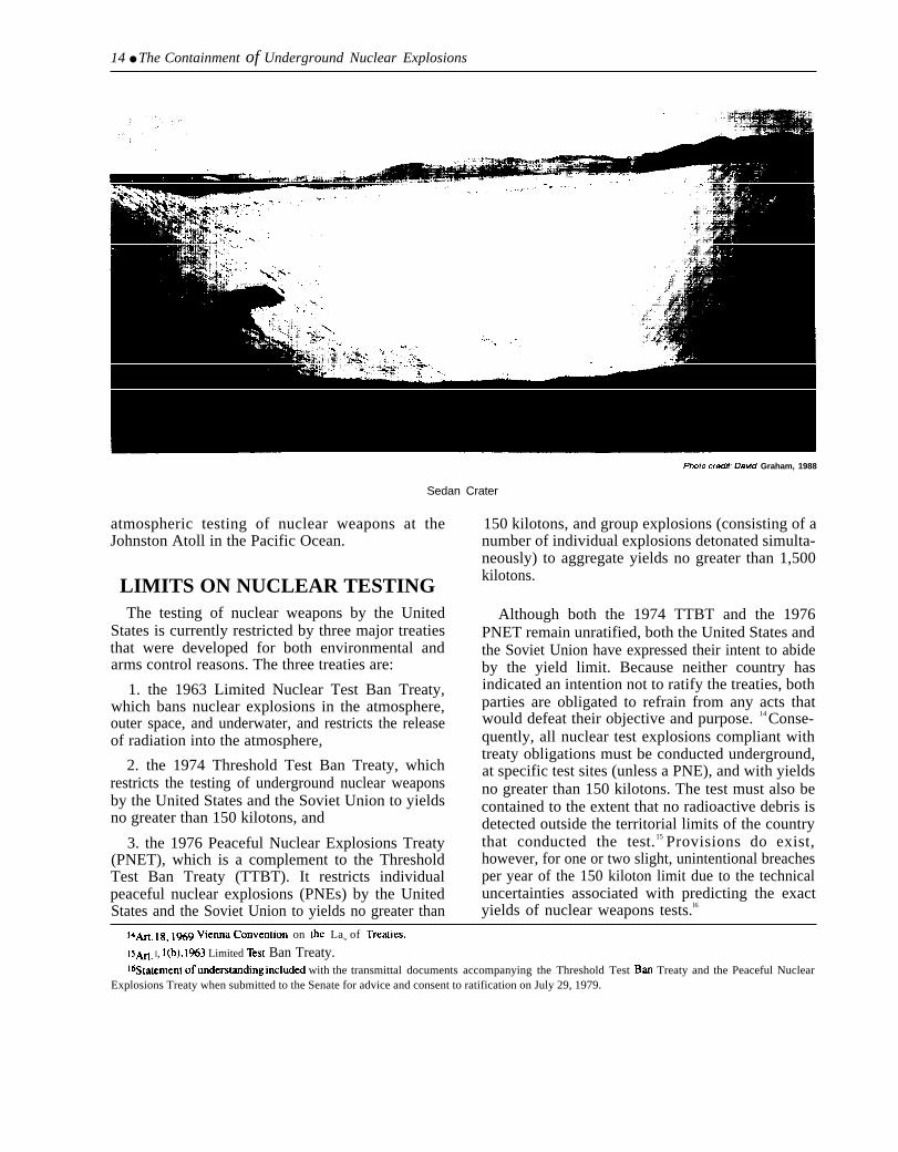
The first test under the Plowshare Program,‘‘Gnome,’ was conducted 4 years later to create anunderground cavity in a large salt deposit. The nextPlowshare experiment, Sedan in 1962, used a 104kiloton explosion to excavate 12 million tons ofearth. In 1965, the concept of ‘nuclear excavation’was refined and proposed as a means of building asecond canal through Panama.12 Three nuclearexcavations were tested under the Plowshare pro-gram ("Cabriolet,” Jan. 26, 1968; “Buggy,” Mar.12, 1968; and “Schooner,” Dec. 12, 1968). Schoo-ner, however, released radioactivity off site and, asa consequence, no future crater test was approved.Consideration of the radiological and logisticalaspects of the project also contributed to its demise,
Estimates of the engineering requirements indicatedthat approximately 250 separate nuclear explosionswith a total yield of 120 megatons would be requiredto excavate the canal through Panama. Furthermore,fallout predictions indicated that 16,000 squarekilometers of territory would need to be evacuatedfor the duration of the operation and several monthsthereafter. 13 Because it was also clear that no levelof radioactivity would be publicly acceptable, theprogram was terminated in the early 1970s.
In 1974, President Richard Nixon signed theThreshold Test Ban Treaty (TTBT) restricting allnuclear test explosions to a defined test site and toyields no greater than 150 kilotons. As a result, allU.S. underground nuclear tests since 1974 have beenconducted at the Nevada Test Site. As part of theearlier 1963 Limited Test Ban Treaty, the UnitedStates established a series of safeguards. One ofthem, “Safeguard C,” requires the United States tomaintain the capability to resume atmospherictesting in case the treaty is abrogated. The Depart-ment of Energy (DOE) and the Defense NuclearAgency continue today to maintain a facility for the
lzne 1956 war over he Suez Canal created the first specific proposals for using INICkSI explosions to create ~ dtemalive can~.
IsBruce A. Bolt, “Nuclear Explosions and Earthquakes, The Parted Veil” San Francisco, CA: W.H. Freeman& Co., 1976, pp. 192-1%.
—
14 ● The Containment of Underground Nuclear Explosions
Photo cradit: David Graham, 1988
Sedan Crater
atmospheric testing of nuclear weapons at theJohnston Atoll in the Pacific Ocean.
LIMITS ON NUCLEAR TESTINGThe testing of nuclear weapons by the United
States is currently restricted by three major treatiesthat were developed for both environmental andarms control reasons. The three treaties are:
1. the 1963 Limited Nuclear Test Ban Treaty,which bans nuclear explosions in the atmosphere,outer space, and underwater, and restricts the releaseof radiation into the atmosphere,
2. the 1974 Threshold Test Ban Treaty, whichrestricts the testing of underground nuclear weaponsby the United States and the Soviet Union to yieldsno greater than 150 kilotons, and
3. the 1976 Peaceful Nuclear Explosions Treaty(PNET), which is a complement to the ThresholdTest Ban Treaty (TTBT). It restricts individualpeaceful nuclear explosions (PNEs) by the UnitedStates and the Soviet Union to yields no greater than
150 kilotons, and group explosions (consisting of anumber of individual explosions detonated simulta-neously) to aggregate yields no greater than 1,500kilotons.
Although both the 1974 TTBT and the 1976PNET remain unratified, both the United States andthe Soviet Union have expressed their intent to abideby the yield limit. Because neither country hasindicated an intention not to ratify the treaties, bothparties are obligated to refrain from any acts thatwould defeat their objective and purpose. 14 Conse-quently, all nuclear test explosions compliant withtreaty obligations must be conducted underground,at specific test sites (unless a PNE), and with yieldsno greater than 150 kilotons. The test must also becontained to the extent that no radioactive debris isdetected outside the territorial limits of the countrythat conducted the test.15 Provisions do exist,however, for one or two slight, unintentional breachesper year of the 150 kiloton limit due to the technicaluncertainties associated with predicting the exactyields of nuclear weapons tests.l6
14~e 18, 1969 Vienna convention on tie Law of Tre~ies,
15~. I, l(b), 1963 Limited lkst Ban Treaty.lbs[~ment of llndel-st~ding included with the transmittal documents accompanying the Threshold Test BarI Treaty and the Peaceful Nuclear
Explosions Treaty when submitted to the Senate for advice and consent to ratification on July 29, 1979.

Chapter 2—The Nuclear Testing Program . 15
OTHER LOCATIONS OFNUCLEAR TESTS
U.S. nuclear test explosions were also conductedin areas other than the Pacific and the Nevada TestSite.
Three tests with yields of 1 to 2 kilotons wereconducted over the South Atlantic as ‘‘OperationArgus.’ ‘ The tests (“Argus I,” Aug. 27, 1958;“Argus H,” Aug. 30, 1958; and “Argus III,” Sept.6, 1958) were detonated at an altitude of 300 milesto assess the effects of high-altitude nuclear detona-tions on communications equipment and missileperformance.
Five tests, all involving chemical explosions butwith no nuclear yield, were conducted at the NevadaBombing Range to study plutonium dispersal. Thetests, “Project 57 NO l,” April 24, 1957; “DoubleTracks,” May 15, 1963; “Clean Slate I,” May 25,1963; “Clean Slate II,” May 31, 1963; and “CleanSlate III,’ June 9, 1963; were safety tests to establishstorage and transportation requirements.
Two tests were conducted in the Tatum Salt Domenear Hattiesburg, Mississippi, as part of the VelaUniform experiments to improve seismic methods ofdetecting underground nuclear explosions. The firsttest ‘Salmon,’ October 22, 1964, was a 5.3 kilotonexplosion that formed an underground cavity. Thesubsequent test “Sterling,” December 3, 1966, was0.38 kt explosion detonated in the cavity formed bySalmon. The purpose of the Salmon/Sterling experi-ment was to assess the use of a cavity in reducing thesize of seismic signals produced by an undergroundnuclear test.17
Three joint government-industry tests were con-ducted as part of the Plowshare Program to developpeaceful uses of nuclear explosions. The experi-ments were designed to improve natural gas extrac-tion by fracturing rock formations. The first test,‘‘Gasbuggy,’ was a 29 kiloton explosion detonatedon December 10, 1967, near Bloomfield, NewMexico. The next two were in Colorado: “Rulison”was a 40 kiloton explosion, detonated near GrandValley on September 10, 1969; and “Rio Blanco”
was a salvo shot of three explosions, each with ayield of 33 kt, detonated near Rifle on May 17, 1973.
Three tests were conducted on Amchitka Island,Alaska. The first (October 29, 1965), “Long Shot”was an 80 kiloton explosion that was part of the VelaUniform project. The second test, “Milrow," Octo-ber 2, 1969, was about a one megaton explosion to‘‘calibrate’ the island and assure that it wouldcontain a subsequent test of the Spartan Anti-Ballistic Missile warhead. The third test, “Canni-kin,” November 6, 1971, was the Spartan warheadtest with a reported yield of “less than fivemegatons. This test, by far the highest-yieldunderground test ever conducted by the UnitedStates, was too large to be safely conducted inNevada. 18
Three individual tests were also conducted invarious parts of the western United States. “Gnome’was a 3 kiloton test conducted on December 10,1961 near Carlsbad, New Mexico, to create a largeunderground cavity in salt as part of a multipurposeexperiment. One application was the possible use ofthe cavity for the storage of oil and gas. “Shoal”was a 12 kiloton test conducted on October 26, 1963near Fallen, Nevada as part of the Vela Uniformproject. ‘‘Faultless” was a test with a yield ofbetween 200 and 1,000 kiloton that was exploded onJanuary 19, 1968, at a remote area near Hot CreekValley, Nevada. Faultless was a ground-motioncalibration test to evaluate a Central Nevada Supple-mental Test Area. The area was proposed as aalternative location for high-yield tests to decreasethe ground shaking in Las Vegas.
THE NEVADA TEST SITEThe Nevada Test Site is located 65 miles north-
west of Las Vegas. It covers 1,350 square miles, artarea slightly larger than Rhode Island (figure 2-2).The test site is surrounded on three sides by anadditional 4,000 to 5,000 square miles belonging toNellis Air Force Base and the Tonopah Test Range.The test site has an administrative center, a controlpoint, and areas where various testing activities areconducted.
At the southern end of the test site is Mercury, theadministrative headquarters and supply base for
17 For a complete ~scusslon of the issues related to Seismic Verification see, U.S. Congress, Office of ‘Ikchnology Assessment, sdSmlC ve@CafiOn
of Nuclear Testing Treaties, OTA-ISC-361, Washington, DC: U.S. Government Printing Office, May 1988.ISW @ictions of ~md motion suggest~ hat ~ ~~ceptable mount (~ te~s of c]afis ~d dol]~s) of damage would OCCIM to structures if
the test was conducted in Nevada.

16 . The Containment of Underground Nuclear Explosions
Figure 2-2--Nevada Test Site
:
SOURCE: Modified from Department of Energy.
DOE contractors and other agencies involved inNevada Operations. Mercury contains a limitedamount of housing for test site personnel and otherground support facilities.
Near the center of the test site, overlookingFrenchman Flat to the South and Yucca Flat to theNorth, is the Control Point (CP). The CP is thecommand headquarters for testing activities and isthe location from which all tests are detonated andmonitored.
Frenchman Flat is the location of the first nucleartest at the test site. A total of 14 atmospheric testsoccurred on Frenchman Flat between 1951 and1962. Most of these tests were designed to determine
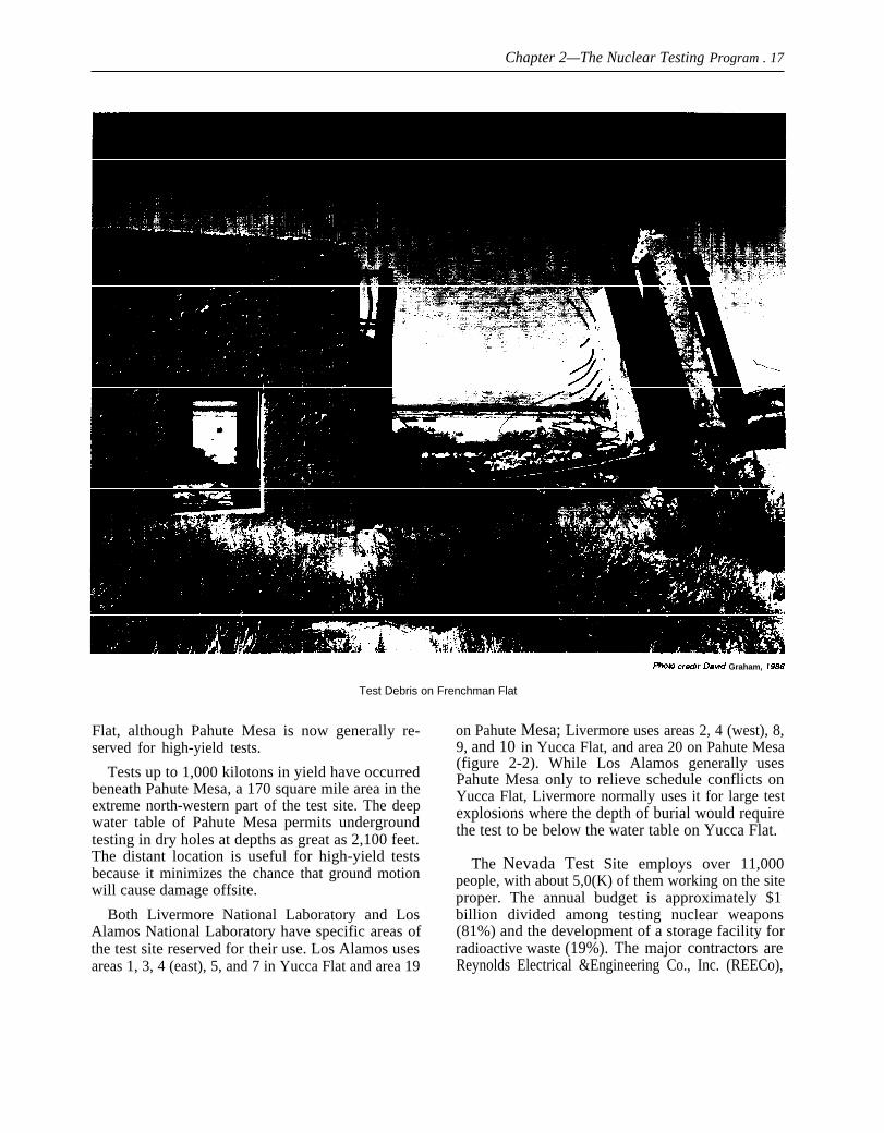
the effects of nuclear explosions on structures andmilitary objects. The area was chosen for its flatterrain which permitted good photography of deto-nations and fireballs. Also, 10 tests were conductedunderground at Frenchman Flat between 1965 and1971. Frenchman Flat is no longer used as a locationfor testing. The presence of carbonate materialmakes the area less suitable for underground testingthan other locations on the test site.19
Yucca Flat is where most underground tests occurtoday. These tests are conducted in vertical drillholes up to 10 feet in diameter and from 600 ft tomore than 1 mile deep. It is a valley 10 by 20 milesextending north from the CP. Tests up to about 300kilotons in yield have been detonated beneath Yucca
1$’~ng ~ explmion, cti~nate material can form carbon dioxide which, under pressure, can cause venting.
Chapter 2—The Nuclear Testing Program . 17
PfWO Crti”t” Dan”d Graham, Ig&7
Test Debris on Frenchman Flat
Flat, although Pahute Mesa is now generally re-served for high-yield tests.
Tests up to 1,000 kilotons in yield have occurredbeneath Pahute Mesa, a 170 square mile area in theextreme north-western part of the test site. The deepwater table of Pahute Mesa permits undergroundtesting in dry holes at depths as great as 2,100 feet.The distant location is useful for high-yield testsbecause it minimizes the chance that ground motionwill cause damage offsite.
Both Livermore National Laboratory and LosAlamos National Laboratory have specific areas ofthe test site reserved for their use. Los Alamos usesareas 1, 3, 4 (east), 5, and 7 in Yucca Flat and area 19
on Pahute Mesa; Livermore uses areas 2, 4 (west), 8,9, and 10 in Yucca Flat, and area 20 on Pahute Mesa(figure 2-2). While Los Alamos generally usesPahute Mesa only to relieve schedule conflicts onYucca Flat, Livermore normally uses it for large testexplosions where the depth of burial would requirethe test to be below the water table on Yucca Flat.
The Nevada Test Site employs over 11,000people, with about 5,0(K) of them working on the siteproper. The annual budget is approximately $1billion divided among testing nuclear weapons(81%) and the development of a storage facility forradioactive waste (19%). The major contractors areReynolds Electrical &Engineering Co., Inc. (REECo),

Edgerton, Germeshausen & Greer (EG&G), Fenix &Scisson, Inc., and Holmes& Narver, Inc. REECo has5,000 employees at the test site for construction,maintenance, and operational support, which in-cludes large diameter drilling and tunneling, on-siteradiation monitoring, and operation of base camps.EG&G has 2,200 employees, who design, fabricate,and operate the diagnostic and scientific equipment.Fenix & Scisson, Inc. handles the design, research,inspection, and procurement for the drilling andmining activities. Holmes & Narver, Inc. has respon-sibility for architectural design, engineering design,and inspection. In addition to contractors, severalgovernment agencies provide support to the testingprogram: the Environmental Protection Agency(EPA) has responsibility for radiation monitoringoutside the Nevada Test Site; the National Oceanicand Atmospheric Administration (NOAA) providesweather analyses and predictions; and the UnitedStates Geological Survey (USGS) provides geologi-cal, geophysical, and hydrological assessments oftest locations.
TYPES OF NUCLEAR TESTS
Presently, an average of more than 12 tests peryear are conducted at the Nevada Test Site. Each testis either at the bottom of a vertical drill hole or at theend of a horizontal tunnel. The vertical drill holetests are the most common (representing over 90%of all tests conducted) and occur either on Yucca Flator, if they are large-yield tests, on Pahute Mesa.Most vertical drill hole tests are for the purpose ofdeveloping new weapon systems. Horizontal tunneltests are more costly and time-consuming. They onlyoccur once or twice a year and are located in tunnelsmined in the Rainier and Aqueduct Mesas. Tunneltests are generally for evaluating the effects (radia-tion, ground shock, etc.) of various weapons onmilitary hardware and systems. In addition, theUnited Kingdom also tests at a rate of about once ayear at the Nevada Test Site.
It takes 6 to 8 weeks to drill a hole depending ondepth and location. The holes used by Livermore andLos Alamos differ slightly. Los Alamos typicallyuses holes with diameters that range from about 4
Chapter 2—The Nuclear Testing Program ● 19
I%oto credir Department of Enetyy
Emplacement Tower for Vertical Drill Hole Test
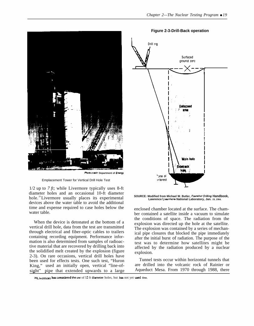
1/2 up to 7 ft; while Livermore typically uses 8-ftdiameter holes and an occasional 10-ft diameterhole. 20 Livermore usually places its experimentaldevices above the water table to avoid the additionaltime and expense required to case holes below thewater table.
When the device is detonated at the bottom of avertical drill hole, data from the test are transmittedthrough electrical and fiber-optic cables to trailerscontaining recording equipment. Performance infor-mation is also determined from samples of radioac-tive material that are recovered by drilling back intothe solidified melt created by the explosion (figure2-3). On rare occasions, vertical drill holes havebeen used for effects tests. One such test, “HuronKing,” used an initially open, vertical “line-of-sight" pipe that extended upwards to a large
Figure 2-3-Drill-Back operation
SOURCE: Modified from Michael W. Butler, PasfstIcIt Dri//ing Handbook,Lawrence Livermore National Laboratory, Jan. 19, 1984.
enclosed chamber located at the surface. The cham-ber contained a satellite inside a vacuum to simulatethe conditions of space. The radiation from theexplosion was directed up the hole at the satellite.The explosion was contained by a series of mechan-ical pipe closures that blocked the pipe immediatelyafter the initial burst of radiation. The purpose of thetest was to determine how satellites might beaffected by the radiation produced by a nuclearexplosion.
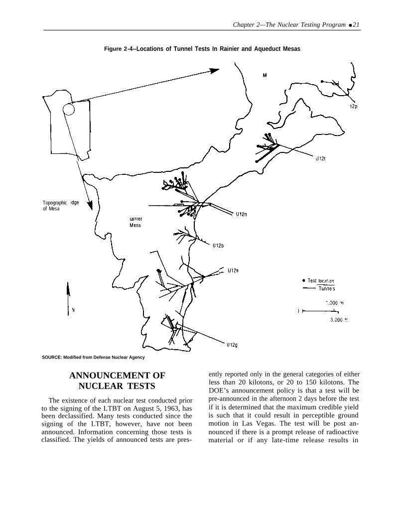
Tunnel tests occur within horizontal tunnels thatare drilled into the volcanic rock of Rainier orAqueduct Mesa. From 1970 through 1988, there. . .
20Llve~~ has c~si&red the U,W of 12 ft diameter holes, but has not yet @ One.

20 ● The Containment of Underground Nuclear Explosions
Huron King Test
have been 31 tunnel tests conducted in Rainier andAqueduct Mesas (figure 2-4). It may require 12months of mining, using three shifts a day, to removethe 1 million cubic feet of rock that may be neededto prepare for a tunnel test.
Effects tests performed within mined tunnels aredesigned to determine the effects of nuclear explosion-produced radiation on missile nose cones, warheads,satellites, communications equipment, and othermilitary hardware. The tunnels are large enough sothat satellites can be tested at full scale in vacuumchambers that simulate outer space. The tests areused to determine how weapons systems willwithstand radiation that might be produced by anearby explosion during a nuclear war. Nuclear
effects tests were the first type of experimentsperformed during trials in the Pacific and were anextensive part of the testing program in the 1950s. Atthat time, many tests occurred above ground andincluded the study of effects on structures and civildefense systems.
Effects tests within cavities provide a means ofsimulating surface explosions underground. A largehemispherical cavity is excavated and an explosionis detonated on or near the floor of the cavity. Thetests are designed to assess the capability of above-ground explosions to transmit energy into theground. This information is used to evaluate thecapability of nuclear weapons to destroy such targetsas missile silos or underground command centers.
Chapter 2—The Nuclear Testing Program ● 21
Figure 2-4--Locations of Tunnel Tests In Rainier and Aqueduct Mesas
Topographicof Mesa
SOURCE: Modified from Defense Nuclear Agency
ANNOUNCEMENT OFNUCLEAR TESTS
The existence of each nuclear test conducted priorto the signing of the LTBT on August 5, 1963, hasbeen declassified. Many tests conducted since thesigning of the LTBT, however, have not beenannounced. Information concerning those tests isclassified. The yields of announced tests are pres-
ently reported only in the general categories of eitherless than 20 kilotons, or 20 to 150 kilotons. TheDOE’s announcement policy is that a test will bepre-announced in the afternoon 2 days before the testif it is determined that the maximum credible yieldis such that it could result in perceptible groundmotion in Las Vegas. The test will be post an-nounced if there is a prompt release of radioactivematerial or if any late-time release results in
22 ● The Containment of Underground Nuclear Explosions
-.Photo cradit: Datid G raham, 1968
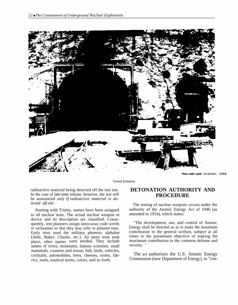
Tunnel Entrance
radioactive material being detected off the test site.In the case of late-time release, however, the test willbe announced only if radioactive material is de-tected off-site.
Starting with Trinity, names have been assignedto all nuclear tests. The actual nuclear weapon ordevice and its description are classified. Conse-quently, test planners assign innocuous code wordsor nicknames so that they may refer to planned tests.Early tests used the military phonetic alphabet(Able, Baker, Charlie, etc.). As more tests tookplace, other names were needed. They includenames of rivers, mountains, famous scientists, smallmammals, counties and towns, fish, birds, vehicles,cocktails, automobiles, trees, cheeses, wines, fab-rics, tools, nautical terms, colors, and so forth.
DETONATION AUTHORITY ANDPROCEDURE
The testing of nuclear weapons occurs under theauthority of the Atomic Energy Act of 1946 (asamended in 1954), which states:
“The development, use, and control of AtomicEnergy shall be directed so as to make the maximumcontribution to the general welfare, subject at alltimes to the paramount objective of making themaximum contribution to the common defense andsecurity. ’
The act authorizes the U.S. Atomic EnergyCommission (now Department of Energy), to "con-


24 ● The Containment of Underground Nuclear Explosions
Photo credit: Defense Nuclear Agency
End of Tunnel
comments in its recommendation letter to the inventory to see if a suitable hole is available or if aPresident. The Nevada Operations Office plans the new one must be drilled.individual tests with the responsible laboratory. Once a hole is selected, the sponsoring laboratory
designs a plan to fill-in (or “stem”) the hole toBoth Livermore and Los Alamos maintain stock- contain the radioactive material produced by the
piles of holes in various areas of the test site.21 When explosion. The USGS and Earth scientists froma specific test is proposed, the lab will check its several organizations analyze the geology surround-
zlE~h ]a~ra~~ o~rates its own drilling crews continuously to maximim the economy of the drilling OpWiltion.

Chapter 2—The Nuclear Testing Program ● 25
ZZW Ch. 3, ‘‘Containment Evaluation Panel.
23~ nuclew ~ety study prepared by DOE Safety Division cont~s safety considerations not re]a(~ to containment, s~h as tie possibility of
premature or inadvertent detonation.Mh ~c ~= of tesB sWnWr~ by tie Defense Nuclear Agency (DNA), the Scientific Advisor is from Smdla National Labor~ory.

26 ● The Containment of Underground Nuclear Explosions
from the sponsoring Laboratory.24 The three mem-bers are all knowledgeable about the weapons-testing program and consist of:
1. an EPA senior scientist with expertise inradiation monitoring,
2. a weather service senior scientist knowledgea-ble in meteorology, and
3. a medical doctor with expertise in radiationmedicine.
Once the test has been approved for execution by theTest Controller’s panel, the Test Controller has soleresponsibility to determine when or whether the testwill be conducted. The Test Controller and AdvisoryPanel members conduct the following series oftechnical meetings to review the test:25
D-7 Safety Planning Meeting: The “D-7 SafetyPlanning Meeting” is held approximately 1 weekbefore the test. This meeting is an informal reviewof the test procedure, the containment plan, theexpected yield, the maximum credible yield, thepotential for surface collapse, the potential groundshock, the expected long-range weather conditions,the location of radiation monitors, the location of allpersonnel, the security concerns (including thepossibility of protesters intruding on the test site),the countdown, the pre-announcement policy, andany other operational or safety aspects related to thetest.
D-1 Safety Planning Meeting: The day before thetest, the D-1 Safety Planning Meeting is held. Thisis an informal briefing that reviews and updates allthe information discussed at the D-7 meeting.
D-1 Containment Briefing: The D-1 ContainmentBriefing is a formal meeting. The laboratory reviewsagain the containment plan and discusses whether allof the stemming and other containment require-ments were met. The meeting determines the extentto which the proposed containment plan was carriedout in the field.26 The laboratory and contractorsprovide written statements on their concurrence ofthe stemming plan.
D-1 Readiness Briefing: The D-1 ReadinessBriefing is a formal meeting to review potential
weather conditions and the predicted radiationfallout pattern for the case of an accidental venting.
The night before the test, the weather servicesends out observers to release weather balloons andbegin measuring wind direction and speed to aheight of 1,400 ft above the ground. The area aroundthe test (usually all areas north of the Control Pointcomplex) is closed to all nonessential personnel. TheEnvironmental Protection Agency deploys monitor-ing personnel off-site to monitor fallout and coordi-nate protective measures, should they be necessary.
D-Day Readiness Briefing: The morning of thetest, the Test Controller holds the “D-Day Readi-ness Briefing. ’ At this meeting, updates of weatherconditions and forecasts are presented. In addition,the weather service reviews the wind and stabilitymeasurements to make final revisions to the falloutpattern in the event of an accidental venting. Thefallout pattern is used to project exposure ratesthroughout the potential affected area. The exposurerates are calculated using the standard radiologicalmodels of whole-body exposure and infant thyroiddose from a family using milk cows in the falloutregion. The status of on-site ground-based andairborne radiation monitoring is reviewed. Thelocation of EPA monitoring personnel is adjusted tothe projected fallout pattern, and the location of allpersonnel on the test site is confined. At the end ofthe meeting, the Scientific Advisor who is chairmanof the Test Controller’s Advisory Panel makes arecommendation to the Test Controller to proceed ordelay.
If the decision is made to proceed, the TestController gives permission for the nuclear device tobe armed. The operation of all radiation monitors,readiness of aircraft, location of EPA personnel, etc.,are confined. If the status remains favorable and theweather conditions are acceptable, the Test Control-ler gives permission to start the countdown and tofire. If nothing abnormal occurs, the countdownproceeds to detonation. If a delay occurs, theappropriate preparatory meetings are repeated.
zd~ tie c= of ~s~ sponsor~ by tie Defense Nuclear Agency (DNA), the Scientific Advisor is from Sandia National Laboratory.2S~~ou@ @ tc~ h~ ~n prcp~atlons inclu~ provisions for ~ ~id~t~ release of radioactive materiat, Sucl
provisions include the deployment of an emergency response team for each test.?6For Cxmp]e, ~~ngs from temperat~e sensors placed in the stemming plugs are examined to dete~ine whe~er tie Plugs have h~d~~.

Chapter 2—The Nuclear Testing Program ● 27
Photo credit: Department of Energy
Test Control Center

Chapter 3
Containing UndergroundNuclear Explosions

.
CONTENTSPage
INTRODUCTION . . . . . . . . . . . . . . . . . . . . . . . . . . . . . . . . . . . . . . . . . . .WHAT HAPPENS DURING AN UNDERGROUND NUCLEAR
Microseconds . . . . . . . . . . . . . . . . . . . . . . . . . . . . . . . . . . . . . . . . . . . . . .Milliseconds . . . . . . . . . . . . . . . . . . . . . . . . . . . . . +. . . . . . . . . . . . . . . . .Tenths of a Second . . . . . . . . . . . . . . . . . . . . . . . . . . . . . . . . . . . . . . . . .A Few Seconds . . . . . . . . . . . . . . . . . . . . . . . . . . . . . . . . . . . . . . . . . . . .Minutes to Days . . . . . . . . . . . . . . . . . . .. .. .. .. .. .. .. ... ........
EXPLOSION . . . . . . . . . . . . . . . . . . . . .. . . . . . . . . . . . . . . . . . . . .. . . . . . . . . . . . . . . . . . . . .. . . . . . . . . . . . . . . . . . . . .. . . . . . . . . . . . . . . . . . . . .
WHY NUCLEAR EXPLOSIONS REMAIN CONTAINED ... ...... . . . . . . . . . . . . . . . .SELECTING LOCATION, DEPTH, AND SPACING: . . . . . . . . . . . . . . . . . . . . . . . . . . . . . .REVIEWING A TEST SITE LOCATION . . . . . . . . . . . . . . . . . . . . . . . . . . . . . . . . . . . . . . . . . . .CONTAINMENT EVALUATION PANEL . . . . . . . . . . . . . . . . . . . . . . . . . . . . . . . . . . . . . . . . .CONTAINING VERTICAL SHAFT TESTS . . . . . . . . . . . . . . . . . . . . . . . . . . . . . . . . . . . . . . .CONTAINING HORIZONTAL TUNNEL TESTS . . . . . . . . . . .. .. .. .. .. .. ... ... ......TYPES OF RADIATION RELEASES . . . . . . . . . . . . . . . . . . . . . . . . . . . . . . . . . . . . . . . . . . . . . .
Containment Failure: . . . . . . . . . . . . . . . . . . . . . . . . . . . . . . . . . . . . . . . . . . . . . . . . . . . . . . . . . . . .Late-Time Seep . . . . . . . . . . . . . . . . . . . . . . . . . . . . . . . . . . . . . . . . . . . . . . . . . . . . . . . . . . . . . . . .Controlled Tunnel Purging . . . . . . . . . . . . . . . . . . . . . . . . . . . . . . . . . . . . . . . . . . . . . . . . . . . . . .Operational Release . . . . . . . . . . . . . . . . . . . . . . . . . . . . . . . . . . . . . . . . . . . . . . . . . . . . . . . . . . . .
RECORD OF CONTAINMENT . . . . . . . . . . . . . . . . . . . . . . . . . . . . . . . . . . . . . . . . . . . . . . . . . . . .Containment Evaluation Panel . . . . . . . . . . . . . . . . . . . . . . . . . . . . . . . . . . . . . . . . . . . . . . . . . . .Vertical Drill Hole ’lasts . . . . . . . . . . . . . . . . . . . . . . . . . . . . . . . . . . . . . . . . . . . . . . . . . . . . . . . .Horizontal Tunnel Tests . . . . . . . . . . . . . . . . . . . . . . . . . . . . . . . . . . . . . . . . . . . . . . . . . . . . . . . . .From the Perspective of Human Health Risk . . . . . . . . . . . . . . . . . . . . . . . . . . . . . . . . . . . . .
A FEW EXAMPLES: . . . . . . . . . . . . . . . . . . . . . . . . . . . . . . . . . . . . . . . . . . . . . . . . . . . . . . . . . . . .IS THERE A REAL ESTATE PROBLEM AT NTS? . . . . . . . . . . . . . . . . . . . . . . . . . . . . . . . .TIRED MOUNTAIN SYNDROME? . . . . . . . . . . . . . . . . . . . . . . . . . . . . . . . . . . . . . . . . . . . . . . . .HOW SAFE IS SAFE ENOUGH? . . . . . . . . . . . . . . . . . . . . . . . . . . . . . . . . . . . . . . . . . . . . . . . . . .
Box3-A. Baneberry . . . . . . . . . . . . .
Figure
. . . .
3-1.3-2.3-3.3-4.3-5.3-6.3-7.3-8.3-9.
3-10.4
31323232323232
35373840414646464747474748484949515154
Page. . . . . . . . . . . . . . . . . . . . . . . . . . . . . . . . . . . . . . . . . . . . . . . 33
FiguresPage
Formation of Stress “Containment Cage” . . . . . . . . . . . . . . . . . . . . . . . . . . . . . . . . . . . . .Minimum Shot Separation for Drill Hole Tests . . . . . . . . . . . . . . . . . . . . . . . . . . . . . . . .Minimum Shot Separation for Tunnel Tests . . . . . . . . . . . . . . . . . . . . . . . . . . . . . . . . . . . .“Typical’’ Stemming Plan . . . . . . . . . . . . . . . . . . . . . . . . . . . . . . . . . . . . . . . . . . . . . . . . . . . .Three Redundant Containment Vessels . . . . . . . . . . . . . . . . . . . . . . . . . . . . . . . . . . . . . . . .Vessel I . . . . . . . . . . . . . . . . . . . . . . . . . . . . . . . . . . . . . . . . . . . . . . . . . . . . . . . . . . . . . . . . . . . .Vessel 1 Closures . . . . . . . . . . . . . . . . . . . . . . . . . . . . . . . . . . . . . . . . . . . . . . . . . . . . . . . . . . .Tunnel Closure Sequence . . . . . . . . . . . . . . . . . . . . . . . . . . . . . . . . . . . . . . . . . . . . . . . . . . . .Typical Post-Shot Configuration . . . . . . . . . . . . . . . . . . . . . . . . . . . . . . . . . . . . . . . . . . . . .Radius of Decrease in Rock Strength . . . . . . . . . . . . . . . . . . . .. .. ... ... ....... . . . . .
35383941424344454653
Table Page3-1. Release From Underground Tests . . . . . . . . . . . . . . . . . . . . .. .. .. . .. .. .. . . . .. .......8 48
Chapter 3
Containing Underground Nuclear Explosions
Underground nuclear tests are designed and reviewed for containment, with redundancy andconservatism in each step.
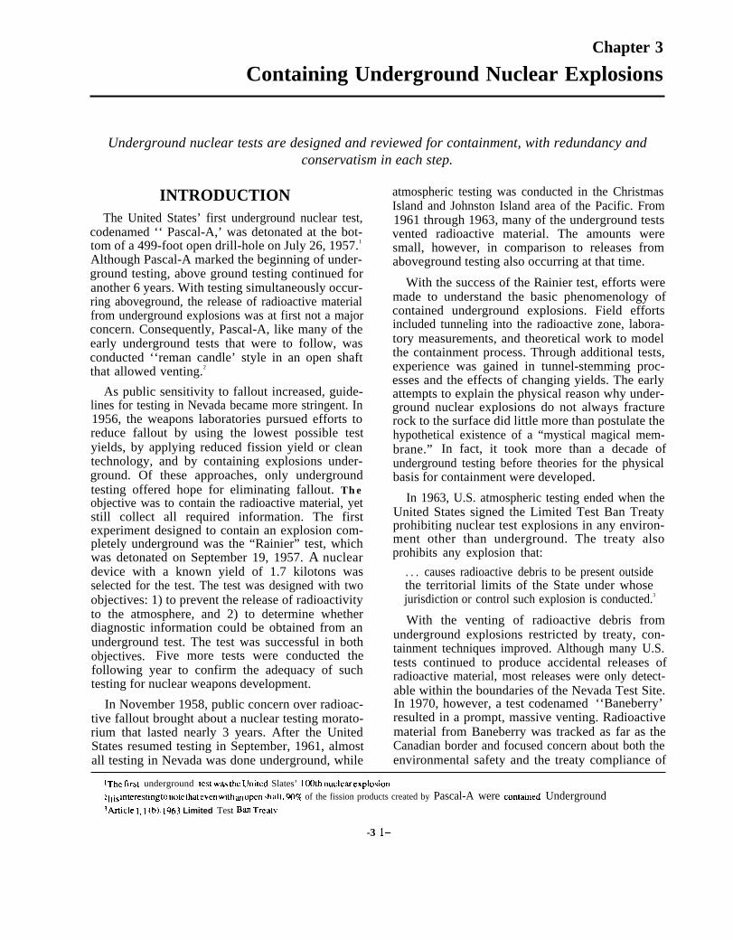
INTRODUCTIONThe United States’ first underground nuclear test,
codenamed ‘‘ Pascal-A,’ was detonated at the bot-tom of a 499-foot open drill-hole on July 26, 1957.1
Although Pascal-A marked the beginning of under-ground testing, above ground testing continued foranother 6 years. With testing simultaneously occur-ring aboveground, the release of radioactive materialfrom underground explosions was at first not a majorconcern. Consequently, Pascal-A, like many of theearly underground tests that were to follow, wasconducted ‘‘reman candle’ style in an open shaftthat allowed venting.2
As public sensitivity to fallout increased, guide-lines for testing in Nevada became more stringent. In1956, the weapons laboratories pursued efforts toreduce fallout by using the lowest possible testyields, by applying reduced fission yield or cleantechnology, and by containing explosions under-ground. Of these approaches, only undergroundtesting offered hope for eliminating fallout. Theobjective was to contain the radioactive material, yetstill collect all required information. The firstexperiment designed to contain an explosion com-pletely underground was the “Rainier” test, whichwas detonated on September 19, 1957. A nucleardevice with a known yield of 1.7 kilotons wasselected for the test. The test was designed with twoobjectives: 1) to prevent the release of radioactivityto the atmosphere, and 2) to determine whetherdiagnostic information could be obtained from anunderground test. The test was successful in bothobjectives. Five more tests were conducted thefollowing year to confirm the adequacy of suchtesting for nuclear weapons development.
In November 1958, public concern over radioac-tive fallout brought about a nuclear testing morato-rium that lasted nearly 3 years. After the UnitedStates resumed testing in September, 1961, almostall testing in Nevada was done underground, while
atmospheric testing was conducted in the ChristmasIsland and Johnston Island area of the Pacific. From1961 through 1963, many of the underground testsvented radioactive material. The amounts weresmall, however, in comparison to releases fromaboveground testing also occurring at that time.
With the success of the Rainier test, efforts weremade to understand the basic phenomenology ofcontained underground explosions. Field effortsincluded tunneling into the radioactive zone, labora-tory measurements, and theoretical work to modelthe containment process. Through additional tests,experience was gained in tunnel-stemming proc-esses and the effects of changing yields. The earlyattempts to explain the physical reason why under-ground nuclear explosions do not always fracturerock to the surface did little more than postulate thehypothetical existence of a “mystical magical mem-brane.” In fact, it took more than a decade ofunderground testing before theories for the physicalbasis for containment were developed.
In 1963, U.S. atmospheric testing ended when theUnited States signed the Limited Test Ban Treatyprohibiting nuclear test explosions in any environ-ment other than underground. The treaty alsoprohibits any explosion that:
. . . causes radioactive debris to be present outsidethe territorial limits of the State under whosejurisdiction or control such explosion is conducted.3
With the venting of radioactive debris fromunderground explosions restricted by treaty, con-tainment techniques improved. Although many U.S.tests continued to produce accidental releases ofradioactive material, most releases were only detect-able within the boundaries of the Nevada Test Site.In 1970, however, a test codenamed ‘‘Baneberry’resulted in a prompt, massive venting. Radioactivematerial from Baneberry was tracked as far as theCanadian border and focused concern about both theenvironmental safety and the treaty compliance of
IThc first underground icst wm the Uni[cd Slates’ 1 Wth nIJdeM explosion.
211 is intere5t1ng [. no(c tha[ even with ~ open shaft, 90% of the fission products created by Pascal-A were contained Underground3A~iClc I, I (b). 1963 Limited Test Ban Trcaly
-3 l–

—
32 ● The Containment of Underground Nuclear Explosions
the testing program. 4 Testing was suspended for 7months while a detailed examination of testingpractices was conducted by the Atomic EnergyCommission. The examination resulted in newtesting procedures and specific recommendationsfor review of test containment. The proceduresinitiated as a consequence of Baneberry are the basisof present-day testing practices.
Today, safety is an overriding concern throughoutevery step in the planning and execution of anunderground nuclear test. Underground nuclear testexplosions are designed to be contained, reviewedfor containment, and conducted to minimize eventhe most remote chance of an accidental release ofradioactive material. Each step of the testing author-ization procedure is concerned with safety; andconservatism and redundancy are built into thesystem.5
WHAT HAPPENS DURING ANUNDERGROUND NUCLEAR
EXPLOSIONThe detonation of a nuclear explosion under-
ground creates phenomena that occur within thefollowing time flames:
Microseconds
Within a microsecond (one-millionth of a sec-ond), the billions of atoms involved in a nuclearexplosion release their energy. Pressures within theexploding nuclear weapon reach several millionpounds per square inch; and temperatures are as highas 100 million degrees Centigrade. A strong shockwave is created by the explosion and moves outwardfrom the point of detonation.
Milliseconds
Within tens of milliseconds (thousandths of asecond), the metal canister and surrounding rock arevaporized, creating a bubble of high pressure steamand gas. A cavity is then formed both by the pressureof the gas bubble and by the explosive momentumimparted to the surrounding rock,
Tenths of a Second
As the cavity continues to expand, the internalpressure decreases. Within a few tenths of a second,the pressure has dropped to a level roughly compara-ble to the weight of the overlying rock. At this point,the cavity has reached its largest size and can nolonger grow.6 Meanwhile, the shockwave created bythe explosion has traveled outward from the cavity,crushing and fracturing rock. Eventually, the shockwave weakens to the point where the rock is nolonger crushed, but is merely compressed and thenreturns to its original state. This compression andrelaxation phase becomes seismic waves that travelthrough the Earth in the same manner as seismicwaves formed by an earthquake.
A Few Seconds
After a few seconds, the molten rock begins tocollect and solidify in a puddle at the bottom of thecavity.7 Eventually, cooling causes the gas pressurewithin the cavity to decrease.
Minutes to Days
When the gas pressure in the cavity declines to thepoint where it is no longer able to support theoverlying rock, the cavity may collapse. The col-lapse occurs as overlying rock breaks into rubble andfalls into the cavity void. As the process continues,the void region moves upward as rubble fallsdownward. The “chimneying” continues until:
. the void volume within the chimney completelyfills with loose rubble,
. the chimney reaches a level where the shape ofthe void region and the strength of the rock cansupport the overburden material. or
. the chimney reaches the surface.
If the chimney reaches the surface, the ground sinksforming a saucer-like subsidence crater. Cavitycollapse and chimney formation typically occurwithin a few hours of the detonation but sometimestake days or months.
4!kc for ex~p]e, Bruce A. Bolt, Nuclear Explosions and Eart@akes San Francisco, CA. (W.H. Freeman k CO., 1976).
~S= ‘ ~~tonatim &~ority and Procedures’ (ch. 2).
%x the next section, “How explosions remain contained, ” for a detailed explanation of cavity formation.7~C So]idlfjed r~k cont~ns most of tie radioa~[ive products from the explosion. The performance Of the nUC@ weapon is ~~Y~~ when s~Plcs
of this material are recovered by drilling back into the cavity.

Chapter 3--Containing Underground Nuclear Explosions ● 33
Box 3-A—Baneberry
The exact cause of the 1970 Baneberry venting still remains a mystery. The original explanation postulatedthe existence of an undetected water table. It assumed that the high temperatures of the explosion produced steamthat vented to the surface. Later analysis, however, discredited this explanation and proposed an alternative scenariobased on three geologic features of the Baneberry site: water-saturated clay, a buried scarp of hard rock, and a nearbyfault. It is thought that the weak, water-saturated clay was unable to support the containment structure: the hard scarpstrongly reflected back the energy of the explosion increasing its force; and the nearby fault provided a pathwaythat gases could travel along. All three of these features seem to have contributed to the venting. Whatever its cause,the Baneberry venting increased attention on containment and, in doing SO, marked the beginning of the present-daycontainment practices.
34 ● The Containment of Underground Nuclear Explosions
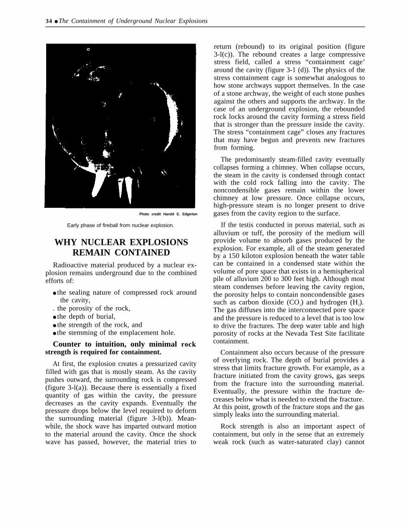
Photo credit Harold E. Edgerton
Early phase of fireball from nuclear explosion.
WHY NUCLEAR EXPLOSIONSREMAIN CONTAINED
Radioactive material produced by a nuclear ex-plosion remains underground due to the combinedefforts of:
● the sealing nature of compressed rock aroundthe cavity,
. the porosity of the rock,● the depth of burial,● the strength of the rock, and● the stemming of the emplacement hole.
Counter to intuition, only minimal rockstrength is required for containment.
At first, the explosion creates a pressurized cavityfilled with gas that is mostly steam. As the cavitypushes outward, the surrounding rock is compressed(figure 3-l(a)). Because there is essentially a fixedquantity of gas within the cavity, the pressuredecreases as the cavity expands. Eventually thepressure drops below the level required to deformthe surrounding material (figure 3-l(b)). Mean-while, the shock wave has imparted outward motionto the material around the cavity. Once the shockwave has passed, however, the material tries to
return (rebound) to its original position (figure3-l(c)). The rebound creates a large compressivestress field, called a stress “containment cage’around the cavity (figure 3-1 (d)). The physics of thestress containment cage is somewhat analogous tohow stone archways support themselves. In the caseof a stone archway, the weight of each stone pushesagainst the others and supports the archway. In thecase of an underground explosion, the reboundedrock locks around the cavity forming a stress fieldthat is stronger than the pressure inside the cavity.The stress “containment cage” closes any fracturesthat may have begun and prevents new fracturesfrom forming.
The predominantly steam-filled cavity eventuallycollapses forming a chimney. When collapse occurs,the steam in the cavity is condensed through contactwith the cold rock falling into the cavity. Thenoncondensible gases remain within the lowerchimney at low pressure. Once collapse occurs,high-pressure steam is no longer present to drivegases from the cavity region to the surface.
If the testis conducted in porous material, such asalluvium or tuff, the porosity of the medium willprovide volume to absorb gases produced by theexplosion. For example, all of the steam generatedby a 150 kiloton explosion beneath the water tablecan be contained in a condensed state within thevolume of pore space that exists in a hemisphericalpile of alluvium 200 to 300 feet high. Although moststeam condenses before leaving the cavity region,the porosity helps to contain noncondensible gasessuch as carbon dioxide (CO2) and hydrogen (H2).The gas diffuses into the interconnected pore spaceand the pressure is reduced to a level that is too lowto drive the fractures. The deep water table and highporosity of rocks at the Nevada Test Site facilitatecontainment.
Containment also occurs because of the pressureof overlying rock. The depth of burial provides astress that limits fracture growth. For example, as afracture initiated from the cavity grows, gas seepsfrom the fracture into the surrounding material.Eventually, the pressure within the fracture de-creases below what is needed to extend the fracture.At this point, growth of the fracture stops and the gassimply leaks into the surrounding material.
Rock strength is also an important aspect ofcontainment, but only in the sense that an extremelyweak rock (such as water-saturated clay) cannot

Chapter 3-Containing Underground Nuclear Explosions ● 35
A
1 ) Cavity expands outward and deforms surrounding rock. 2) Natural resistance to deformation stops expansion. 3) Cavity contracts(rebounds) from elastic unloading of distant rock. 4) Rebound locks in compressive residual stress around cavity.
SOURCE: Modified from Lawrenee Lwermore National Laboratory.
support a stress containment cage. Detonation withinweak, saturated clay is thought to have been a factorin the release of the Baneberry test. As a result, sitescontaining large amounts of water-saturated clay arenow avoided.
The final aspect of containment is the stemmingthat is put in a vertical hole after the nuclear devicehas been emplaced. Stemming is designed to preventgas from traveling up the emplacement hole. Imper-meable plugs, located at various distances along thestemming column, force the gases into the surround-ing rock where it is ‘‘sponged up’ in the pore spaces.
How the various containment features performdepends on many variables: the size of the explo-sion, the depth of burial, the water content of therock, the geologic structure, etc. Problems mayoccur when the containment cage does not formcompletely and gas from the cavity flows eitherthrough the emplacement hole or the overburdenmaterial. 8 When the cavity collapses, the steamcondenses and only noncondensible gases such ascarbon dioxide (CO2) and hydrogen (H2) remain inthe cavity.9 The CO2 and H2 remain in the chimneyif there is available pore space. If the quantity ofnoncondensible gases is large, however, they can actas a driving force to transport radioactivity through
the chimney or the overlying rock. Consequently,the amount of carbonate material and water in therock near the explosion and the amount of ironavailable for reaction are considered when evaluat-ing containment.10
SELECTING LOCATION, DEPTH,AND SPACING
The site for conducting a nuclear test is, at first,selected only on a tentative basis. The final decisionis made after various site characteristics have beenreviewed. The location, depth of burial, and spacingare based on the maximum expected yield for thenuclear device, the required geometry of the test, andthe practical considerations of scheduling, conven-ience, and available holes. If none of the inventoryholes are suitable, a site is selected and a holedrilled. 11
The first scale for determining how deep anexplosion should be buried was derived from theRainier test in 1957. The depth. based on the cuberoot of the yield, was originally:
Depth = 300 (yield)1/3
where depth was measured in feet and yield in
ELWk of a ,qfess ‘‘containment cage’ may not be a serious problem if the medium is sufticently porous or if the depth of burial is suflicent.
‘Whe C02 is formed from the vaporization of carbonate material; while the Hz is formed when water reacts with the iron in the nuclear device anddiagnostics equipment.
l% ~M~nate mate-id ~ F~enChm~ Flat created co2 hat 15 thought to have caused a ~ep during the DiagOn~ Line test (Nov. 24, 19’7 1 ). Diagonal
Line was the last test on Frenchman Flat; the area is currently considered impractical for underground testing largely because of the carbonate matcnal.IISW. ch. 2, ‘ ‘The Nevada Tkst Site,” for a description of the areas each Laboratory uses for testing.

36 ● The Containment of Underground Nuclear Explosions
Photo credit: Department of Energy
Blanca containment failure, 1958.
kilotons. The first few tests after Rainier, however, thus became: 300 (yield)’/’ “plus-a-few-hundred-were detonated at greater depths than this formula f e e t .requires because it was more convenient to minetunnels deeper in the Mesa. It was not until‘‘ Blanca,’ October 30, 1958, that a test wasconducted exactly at 300 (yield) l/3 feet to test thedepth scale. The containment of the Blanca explo-sion, however, was unsuccessful and resulted in asurface venting of radioactive material. As a conse-quence, the depth scale was modified to include theaddition of a few hundred feet as a safety factor and
Today, the general depth of burial can be approxi-mated by the equation:
Depth = 400 (yield)’ /q,
where depth is measured in feet and yield inkilotons. 12 The minimum depth of burial, however,is 600 feet. 13 Consequently, depths of burial varyfrom 600 feet for a low-yield device, to about 2,100feet for a large-yield test. The depth is scaled to the
IZ’ ‘~b]ic Safety for Nuclear Weapons TCSIS, ” Unlmd States Environmental Protection Agency, January, 1984.!sThe &)().fW[ dcp~ ~= chosen as a minimum after a stalisti~al study show~ that ~C likelihood of a seep of radioactive makrid K) the surface for
explosions buried 600 feet or more was about 1/2 as great as for explosions at less than 500 feet, even if they were buried at the same scale-depth ineaeh case.

Chapter Containing Underground Nuclear Explosions ● 37
‘‘maximum credible yield’ that the nuclear deviceis thought physically capable of producing, not tothe design yield or most likely yield. 14
Whether a test will be conducted on Pahute Mesaor Yucca Flat depends on the maximum credibleyield. Yucca Flat is closer to support facilities andtherefore more convenient, while the deep watertable at Pahute Mesa is more economical for largeyield tests that need deep, large diameter emplace-ment holes. Large yield tests in small diameter holes(less than 7 feet) can be conducted in Yucca Flat. Atest area may also be chosen to avoid schedulingconflicts that might result in a test damaging the holeor diagnostic equipment of another nearby test. Oncethe area has been chosen, several candidate sites areselected based on such features as: proximity toprevious tests or existing drill holes; geologicfeatures such as faults, depth to basement rock, andthe presence of clays or carbonate materials; andpractical considerations such as proximity to powerlines, roads, etc.
In areas well suited for testing, an additional siteselection restriction is the proximity to previoustests. For vertical drill hole tests, the minimum shotseparation distance is about one-half the depth ofburial for the new shot (figure 3-2). For shallowshots, this separation distance allows tests to bespaced so close together that in some cases, thesurface collapse craters coalesce. The 1/2 depth ofburial distance is a convention of convenience,rather than a criterion for containment.15 It is, forexample, difficult to safely place a drilling rig tooclose to an existing collapse crater.
Horizontal tunnel tests are generally spaced witha minimum shot separation distance of twice thecombined cavity radius plus 100 feet, measuredfrom the point of detonation (called the “workingpoint”) (figure 3-3). In other words, two tests with100 foot radius cavities would be separated by 300feet between cavities, or 500 feet (center to center).The size of a cavity formed by an explosion isproportional to the cube root of the yield and can beestimated by:
Radius = 55 (yield) ’h,
where the radius is measured in feet and the yield in
kilotons. For example, an 8 kiloton explosion wouldbe expected to produce an underground cavity withapproximately a 110 foot radius. Two such testexplosions would require a minimum separationdistance of 320 feet between cavities or 540 feetbetween working points.
Occasionally, a hole or tunnel is found to beunsuitable for the proposed test. Such a situation,however, is rare, occurring at a rate of about 1 out of25 for a drill hole test and about 1 out of 15 for atunnel test. 16 Usually, a particular hole that is foundunacceptable for one test can be used for another testat a lower yield.
REVIEWING A TEST SITELOCATION
Once the general parameters for a drill-hole havebeen selected, the sponsoring laboratory requests apre-drill Geologic Data Summary (GDS) from theU.S. Geological Survey. The GDS is a geologicinterpretation of the area that reviews the three basicelements: the structures, the rock type, and the watercontent. The U.S. Geological Survey looks forfeatures that have caused containment problems inthe past. Of particular concern is the presence of anyfaults that might become pathways for the release ofradioactive material, and the close location of hardbasement rock that may reflect the energy created bythe explosion, Review of the rock type checks forfeatures such as clay content which would indicatea weak area where it may be difficult for the hole toremain intact, and the presence of carbonate rockthat could produce CO2. Water content is alsoreviewed to predict the amount of steam and H2 thatmight be produced. If the geology indicates less thanideal conditions, alternate locations may be sug-gested that vary from less than a few hundred feetfrom the proposed site to an entirely different area ofthe test site.
When the final site location is drilled, data arecollected and evaluated by the sponsoring labora-tory. Samples and geophysical logs, including down-hole photography, are collected and analyzed. TheU.S. Geological Survey reviews the data, consultswith the laboratory throughout the process, andreviews the accuracy of the geologic interpretations.
IQk mmy cwws tie muimum credible yield is significantly larger than the expected yield for a nuclear device.
ISA.S di=uw~ ]aler, testing in previously fractured rock is not considered a containment risk in mOSt iM3WX.
1- ~rw ~culon5 tuMe]5 have &n abandoned ~auw of un~[icipa[ed conditions such ~$ tie di~overy of a fau]t or the presence of too muchwater,

38 ● The Containment of Underground Nuclear Explosions
Figure 3-2-Minimum Shot Separation for Drill Hole Tests
Yucca flats
Diagram to approximate scale
Scale illustration of the minimum separation distance (1/2 depth of burial) for vertical drill hole tests. Thedepth of burial is based on the maximum credible yield.
SOURCE: Office of Technology Assessment, 1989
To confirm the accuracy of the geologic descriptionand review and evaluate containment considera-tions, the Survey also attends the host laboratory’ssite proposal presentation to the Containment Evalu-ation Panel.
CONTAINMENT EVALUATIONPANEL
One consequence of the Baneberry review was therestructuring of what was then called the TestEvaluation Panel. The panel was reorganized andnew members with a wider range of geologic andhydrologic expertise were added. The new panel wasnamed the Containment Evaluation Panel (CEP);and their first meeting was held in March, 1971.
The Containment Evaluation Panel presentlyconsists of a Chairman and up to 11 panel members.
Six of the panel members are representatives fromLawrence Livermore National Laboratory, Los AlamosNational Laboratory, Defense Nuclear Agency, San-dia National Laboratory, U.S. Geological Survey,and the Desert Research Institute. An additional 3 to5 members are also included for their expertise indisciplines related to containment. The chairman ofthe panel is appointed by the Manager of NevadaOperations (Department of Energy), and panelmembers are nominated by the member institutionwith the concurrence of the chairman and approvalof the Manager. The panel reports to the Manager ofNevada Operations.
Practices of the Containment Evaluation Panelhave evolved throughout the past 18 years; however,their purpose, as described by the Containment

Chapter Containing Underground Nuclear Explosions ● 39
Figure 3-3--Minimum Shot Separation for Tunnel Tests
Rainier Mesa
Tunnel tests are typicallyoverburied. Collapse chimneysdo not usually extend to surface.
I
Diagram to approximate scale
Scale illustration of the minimum separation distance (2 combined cavity radii plus 100 feet) forhorizontal tunnel tests. Tunnel tests are typically overburied. Collapse chimneys do not usually extendto the surface.
SOURCE: Office of Technology Assessment, 1989
Evaluation Charter, remains specifically defined as 4. maintain a historical record of each evaluationfollows:17 and of the data, proceedings, and discussions
pertaining thereto.
1.
2.
3.
evaluate, as an independent organization re-porting to the Manager of Nevada Operations,the containment design of each proposednuclear test;
assure that all relevant data available forproper evaluation are considered;
advise the manager of Nevada Operations ofthe technical adequacy of such design from theviewpoint of containment, thus providing themanager a basis on which to request detona-tion authority; and
Although the CEP is charged with rendering ajudgment as to the adequacy of the design of thecontainment, the panel does not vote. Each memberprovides his independent judgment as to the pros-pect of containment, usually addressing his own areaof expertise but free to comment on any aspect of thetest. The Chairman is in charge of summarizingthese statements in a recommendation to the man-ager on whether to proceed with the test, based onlyon the containment aspects. Containment Evalua-tion Panel guidelines instruct members to make theirjudgments in such a way that:
17 Cont~ent Ev~u~ti~n ~~er, June 1, 1986, s~ti~n II.

—
40 ● The Containment of Underground Nuclear Explosions
Considerations of cost, schedules, and test objectivesshall not enter into the review of the technicaladequacy of any test from the viewpoint of contain-ment. 18
Along with their judgments on containment, eachpanel member evaluates the probability of contain-ment using the following four categories: 19
1.
2.
3.
4.
Category A: Considering all containment fea-tures and appropriate historical, empirical, andanalytical data, the best judgment of themember indicates a high confidence in suc-cessful containment as defined in VIII.F.below.Category B: Considering all containment fea-tures and appropriate historical, empirical, andanalytical data, the best judgment of themember indicates a less, but still adequate,degree of confidence in successful contain-ment as defined in VIII.F. below.Category C’: Considering all containment fea-tures and appropriate historical, empirical, andanalytical data, the best judgment of themember indicates some doubt that successfulcontainment, as described in VIII.F. below,will be achieved.Unable to Categorize
Successful containment is defined for the CEP as:
. . . no radioactivity detectable off-site as measuredby normal monitoring equipment and no unantici-pated release of activity on-site.
The Containment Evaluation Panel does not havethe direct authority to prevent a test from beingconducted. Their judgment, both as individuals andas summarized by the Chairman, is presented to theManager. The Manager makes the decision as towhether a Detonation Authority Request will bemade. The statements and categorization from eachCEP member are included as part of the permanentDetonation Authority Request.
Although the panel only advises the Manager, itwould be unlikely for the Manager to request
detonation if the request included a judgment by theCEP that the explosion might not be contained. Therecord indicates the influence of the CEP. Sinceformation of the panel in 1970, there has never beena Detonation Authority Request submitted for ap-proval with a containment plan that received a “C”(“some doubt”) categorization from even onemember. 20 21
The Containment Evaluation Panel serves anadditional role in improving containment as aconsequence of their meetings. The discussions ofthe CEP provide an ongoing forum for technicaldiscussions of containment concepts and practices.As a consequence, general improvements to contain-ment design have evolved through the panel discus-sions and debate.
CONTAINING VERTICALSHAFT TESTS
Once a hole has been selected and reviewed, astemming plan is made for the individual hole. Thestemming plan is usually formulated by adaptingpreviously successful stemming plans to the particu-larities of a given hole. The objective of the plan isto prevent the emplacement hole from being the pathof least resistance for the flow of radioactivematerial. In doing so, the stemming plan must takeinto account the possibility of only a partial collapse:if the chimney collapse extends only halfway to thesurface, the stemming above the collapse mustremain intact.
Lowering the nuclear device with the diagnosticsdown the emplacement hole can take up to 5 days.A typical test will have between 50 and 250diagnostic cables with diameters as great as 15/~inches packaged in bundles through the stemmingcolumn. After the nuclear device is lowered into theemplacement hole, the stemming is installed. Figure3-4 shows a typical stemming plan for a Lawrence
18conta~ment Ev~~ion Pi ne ] ch~r, June 1, 1986, Swtion 111-D.
lgcont~ent Ev~uation Panel Chaner, June 1, 1986, Section WI.
me grading system for containment plans has evolved since the early 1970’s. Prior to April, 1977, the Containment Evacuation Panel categorizedtests using the Roman numerals (I-IV) where 1-111 had about the same meaning as A-C and IV was a D which eventually was dropped as a letter andjust became ‘‘unable to categorize. ”
21 However, one shot (Mmdo) was submitted with an “unable to categorize” categorization, Mundo was a joint US-UK test conducted on May 1,1984.
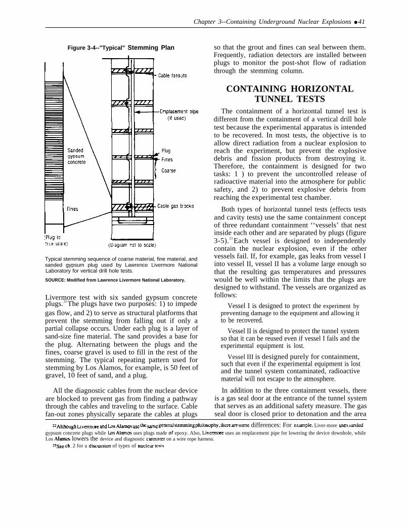
Chapter 3--Containing Underground Nuclear Explosions ● 41
Figure 3-4--"Typical” Stemming Plan
Plug
Typical stemming sequence of coarse material, fine material, andsanded gypsum plug used by Lawrence Livermore NationalLaboratory for vertical drill hole tests.
SOURCE: Modified from Lawrence Livermore National Laboratory.
Livermore test with six sanded gypsum concreteplugs.22 The plugs have two purposes: 1) to impedegas flow, and 2) to serve as structural platforms thatprevent the stemming from falling out if only apartial collapse occurs. Under each plug is a layer ofsand-size fine material. The sand provides a base forthe plug. Alternating between the plugs and thefines, coarse gravel is used to fill in the rest of thestemming. The typical repeating pattern used forstemming by Los Alamos, for example, is 50 feet ofgravel, 10 feet of sand, and a plug.
All the diagnostic cables from the nuclear deviceare blocked to prevent gas from finding a pathwaythrough the cables and traveling to the surface. Cablefan-out zones physically separate the cables at plugs
so that the grout and fines can seal between them.Frequently, radiation detectors are installed betweenplugs to monitor the post-shot flow of radiationthrough the stemming column.
CONTAINING HORIZONTALTUNNEL TESTS
The containment of a horizontal tunnel test isdifferent from the containment of a vertical drill holetest because the experimental apparatus is intendedto be recovered. In most tests, the objective is toallow direct radiation from a nuclear explosion toreach the experiment, but prevent the explosivedebris and fission products from destroying it.Therefore, the containment is designed for twotasks: 1 ) to prevent the uncontrolled release ofradioactive material into the atmosphere for publicsafety, and 2) to prevent explosive debris fromreaching the experimental test chamber.
Both types of horizontal tunnel tests (effects testsand cavity tests) use the same containment conceptof three redundant containment ‘‘vessels’ that nestinside each other and are separated by plugs (figure3-5).23 Each vessel is designed to independentlycontain the nuclear explosion, even if the othervessels fail. If, for example, gas leaks from vessel Iinto vessel II, vessel II has a volume large enough sothat the resulting gas temperatures and pressureswould be well within the limits that the plugs aredesigned to withstand. The vessels are organized asfollows:
Vessel I is designed to protect the experiment bypreventing damage to the equipment and allowing itto be recovered.
Vessel II is designed to protect the tunnel systemso that it can be reused even if vessel I fails and theexperimental equipment is lost.
Vessel III is designed purely for containment,such that even if the experimental equipment is lostand the tunnel system contaminated, radioactivematerial will not escape to the atmosphere.
In addition to the three containment vessels, thereis a gas seal door at the entrance of the tunnel systemthat serves as an additional safety measure. The gasseal door is closed prior to detonation and the area
&!A]though L;ve~Ore ~d ~~ ~amos ~~ [he WC gencr~ stemming philosophy, [here Me some differences: For example, Liver-more U.WS sandd
gypsum concrete plugs while Ims Alamos uses plugs made of epoxy. Also, Livermore uses an emplacement pipe for lowering the device downhole, whileLos Alarms lowers the device and diagnostic carmister on a wire rope harness.
ZSSW ch. 2 for a dixussion of types of nuc]ew tests.
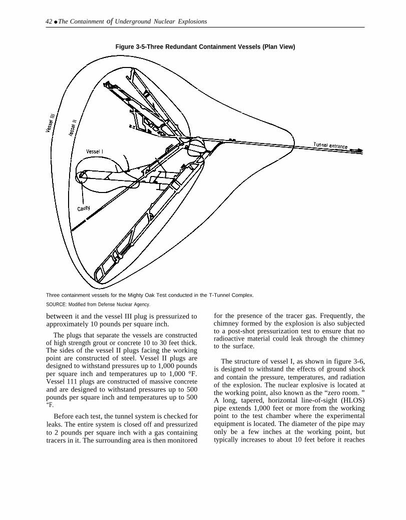
42 ● The Containment of Underground Nuclear Explosions
Figure 3-5-Three Redundant Containment Vessels (Plan View)
Three containment vessels for the Mighty Oak Test conducted in the T-Tunnel Complex.
SOURCE: Modified from Defense Nuclear Agency.
between it and the vessel III plug is pressurized toapproximately 10 pounds per square inch.
The plugs that separate the vessels are constructedof high strength grout or concrete 10 to 30 feet thick.The sides of the vessel II plugs facing the workingpoint are constructed of steel. Vessel II plugs aredesigned to withstand pressures up to 1,000 poundsper square inch and temperatures up to 1,000 °F.Vessel 111 plugs are constructed of massive concreteand are designed to withstand pressures up to 500pounds per square inch and temperatures up to 500“F.
Before each test, the tunnel system is checked forleaks. The entire system is closed off and pressurizedto 2 pounds per square inch with a gas containingtracers in it. The surrounding area is then monitored
for the presence of the tracer gas. Frequently, thechimney formed by the explosion is also subjectedto a post-shot pressurization test to ensure that noradioactive material could leak through the chimneyto the surface.
The structure of vessel I, as shown in figure 3-6,is designed to withstand the effects of ground shockand contain the pressure, temperatures, and radiationof the explosion. The nuclear explosive is located atthe working point, also known as the “zero room. ”A long, tapered, horizontal line-of-sight (HLOS)pipe extends 1,000 feet or more from the workingpoint to the test chamber where the experimentalequipment is located. The diameter of the pipe mayonly be a few inches at the working point, buttypically increases to about 10 feet before it reaches
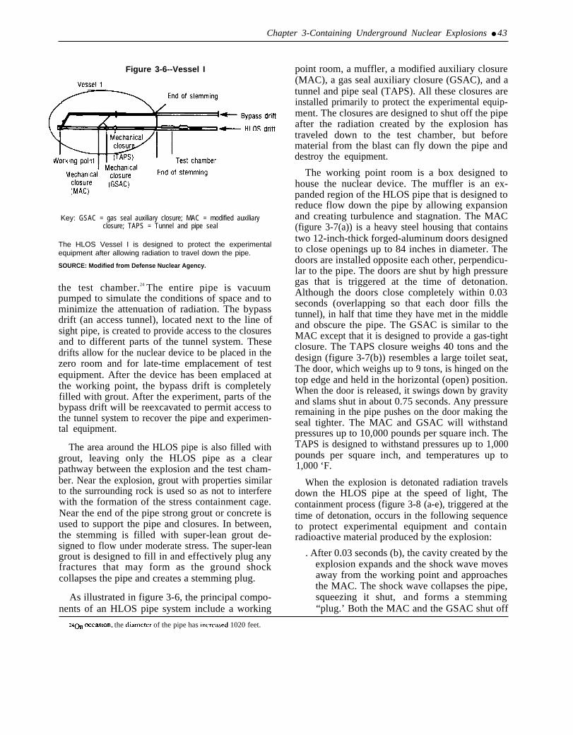
Chapter 3-Containing Underground Nuclear Explosions ● 43
Figure 3-6--Vessel I
Key: GSAC = gas seal auxiliary closure; MAC = modified auxiliaryclosure; TAPS = Tunnel and pipe seal
The HLOS Vessel I is designed to protect the experimentalequipment after allowing radiation to travel down the pipe.
SOURCE: Modified from Defense Nuclear Agency.
the test chamber.24 The entire pipe is vacuumpumped to simulate the conditions of space and tominimize the attenuation of radiation. The bypassdrift (an access tunnel), located next to the line ofsight pipe, is created to provide access to the closuresand to different parts of the tunnel system. Thesedrifts allow for the nuclear device to be placed in thezero room and for late-time emplacement of testequipment. After the device has been emplaced atthe working point, the bypass drift is completelyfilled with grout. After the experiment, parts of thebypass drift will be reexcavated to permit access tothe tunnel system to recover the pipe and experimen-tal equipment.
The area around the HLOS pipe is also filled withgrout, leaving only the HLOS pipe as a clearpathway between the explosion and the test cham-ber. Near the explosion, grout with properties similarto the surrounding rock is used so as not to interferewith the formation of the stress containment cage.Near the end of the pipe strong grout or concrete isused to support the pipe and closures. In between,the stemming is filled with super-lean grout de-signed to flow under moderate stress. The super-leangrout is designed to fill in and effectively plug anyfractures that may form as the ground shockcollapses the pipe and creates a stemming plug.
As illustrated in figure 3-6, the principal compo-nents of an HLOS pipe system include a working
point room, a muffler, a modified auxiliary closure(MAC), a gas seal auxiliary closure (GSAC), and atunnel and pipe seal (TAPS). All these closures areinstalled primarily to protect the experimental equip-ment. The closures are designed to shut off the pipeafter the radiation created by the explosion hastraveled down to the test chamber, but beforematerial from the blast can fly down the pipe anddestroy the equipment.
The working point room is a box designed tohouse the nuclear device. The muffler is an ex-panded region of the HLOS pipe that is designed toreduce flow down the pipe by allowing expansionand creating turbulence and stagnation. The MAC(figure 3-7(a)) is a heavy steel housing that containstwo 12-inch-thick forged-aluminum doors designedto close openings up to 84 inches in diameter. Thedoors are installed opposite each other, perpendicu-lar to the pipe. The doors are shut by high pressuregas that is triggered at the time of detonation.Although the doors close completely within 0.03seconds (overlapping so that each door fills thetunnel), in half that time they have met in the middleand obscure the pipe. The GSAC is similar to theMAC except that it is designed to provide a gas-tightclosure. The TAPS closure weighs 40 tons and thedesign (figure 3-7(b)) resembles a large toilet seat,The door, which weighs up to 9 tons, is hinged on thetop edge and held in the horizontal (open) position.When the door is released, it swings down by gravityand slams shut in about 0.75 seconds. Any pressureremaining in the pipe pushes on the door making theseal tighter. The MAC and GSAC will withstandpressures up to 10,000 pounds per square inch. TheTAPS is designed to withstand pressures up to 1,000pounds per square inch, and temperatures up to1,000 ‘F.
When the explosion is detonated radiation travelsdown the HLOS pipe at the speed of light, Thecontainment process (figure 3-8 (a-e), triggered at thetime of detonation, occurs in the following sequenceto protect experimental equipment and containradioactive material produced by the explosion:
. After 0.03 seconds (b), the cavity created by theexplosion expands and the shock wave movesaway from the working point and approachesthe MAC. The shock wave collapses the pipe,squeezing it shut, and forms a stemming“plug.’ Both the MAC and the GSAC shut off
zq~ ~cmlon, the di~cter of the pipe has inm-ca..ed 1020 feet.

44 ● The Containment of Underground Nuclear Explosions
Figure 3-7—Vessel I Closures
A)
Mechanical closures(MAC/GSAC)
Pre-fire geometry
closure(TAPS)
Approximate closed FAC geometry
Fast acting closure(FAC)
A) Mechanical Closures (MAC/GSAC)B) Tunnel and Pipe Seal (TAPS)C) Fast Acting Closure (FAC)
SOURCE: Modified from Defense Nuclear Agency.
the pipe ahead of the shock wave to prevent enough to squeeze the pipe shut. The stemmingearly flow of high-velocity gas and debris into plug stops forming at about the distance wherethe experiment chamber. the first mechanical pipe closure is located.
● After 0.05 seconds (c), the ground shock moves . After 0.2 seconds (d), the cavity growth ispast the second closure and is no longer strong complete. The rebound from the explosion

Chapter 3--Containing Underground Nuclear Explosions ● 45
A) Zero Time: Explosion is detonated and the first two mechanical closures are fired. B) Within 0,03 seconds, a stemming plug is beingformed and mechanical pipe closure has occurred. C) Within 0.05 seconds, the stemming plug has formed. D) Within 0.2 seconds, cavitygrowth is complete and a surrounding compressive residual stress field has formed, E) Within 0.75 seconds, closure is complete.
SOURCE. Modified from Defense Nuclear Agency.

46 ● The Containment of Underground Nuclear Explosions
locks in the residual stress field, therebyforming a containment cage. The shock wavepasses the test chamber.
. After 0.75 seconds (e), the final mechanical seal(TAPS) closes, preventing late-time explosiveand radioactive gases from entering the testchamber.
The entire closure process for containment takesless than 3/4 of a second. Because the tests aretypically buried at a depth greater than necessary forcontainment, the chimney does not reach the surfaceand a collapse crater normally does not form. Atypical post-shot chimney configuration with itsapproximate boundaries is shown in figure 3-9.
In lower yield tests, such as those conducted in theP-tunnel complex, the first mechanical closure is aFast Acting Closure (FAC) rather than a MAC.25
The FAC (figure 3-7(c)) closes in 0.001 seconds andcan withstand pressures of 30,000 pounds per squareinch. The FAC acts like a cork, blocking off theHLOS pipe early, and preventing debris and stem-ming material from flying down the pipe. A similarclosure is currently being developed for larger yieldtunnel tests.
TYPES OF RADIATION RELEASESTerms describing the release or containment of
underground nuclear explosions have been refinedto account for the volume of the material and theconditions of the release. The commonly used termsare described below.
Containment Failure
Containment failures are releases of radioactivematerial that do not fall within the strict definition ofsuccessful containment, which is described by theDepartment of Energy as:
Containment such that a test results in no radioac-tivity detectable off site as measured by normalmonitoring equipment and no unanticipated releaseof radioactivity onsite. Detection of noble gases thatappear onsite long after an event, due to changingatmospheric conditions, is not unanticipated. Antici-pated releases will be designed to conform tospecific guidance from DOE/HQ.26
Containment failures are commonly described as:
Approximatechimneyboundary
n
. . . . . . . .. . . . . . . . . .. . . . . . . . . .. . . . . . . . . .. . . . . . . . . .. . . . . . . . . .. . . . . . . . . .. . .
Tunnel shots are typically overburied and the collapse chimneyrarely extends to the surface.
SOURCE: Modified from Defense Nuclear Agency.
Ventings
Ventings are prompt, massive, uncontrolled re-leases of radioactive material. They are character-ized as active releases under pressure, such as whenradioactive material is driven out of the ground bysteam or gas. ‘‘ Baneberry,’ in 1970, is the lastexample of an explosion that ‘‘vented. ”
Seeps
Seeps, which are not visible, can only be detectedby measuring for radiation. Seeps are characterizedas uncontrolled slow releases of radioactive materialwith little or no energy.
Late-Time Seep
Late-time seeps are small releases of nonconden-sable gases that usually occur days or weeks after avertical drill hole test. The noncondensable gasesdiffuse up through the pore spaces of the overlyingrock and are thought to be drawn to the surface by adecrease in atmospheric pressure (called “atmos-pheric pumping”).
25~ p-t~e] complex is rnlned in Aqueduct Mesa ~d h~ ]ess overb~den (h~ the Nw.nnel complex in Rainier Mesa. Therefore, p-tUfIne] is
generally used for lower yield tests.~Satlon VIII.F, Containrnen[ Evaluation Panel Charter.

Chapter 3--Containing Underground Nuclear Explosions ● 47
Photo credit: David Graham
Fast acting closure.
Controlled Tunnel Purging
Controlled tunnel purging is an intentional releaseof radioactive material to recover experimentalequipment and ventilate test tunnels. During acontrolled tunnel purging, gases from the tunnel arefiltered, mixed with air to reduce the concentration,and released over time when weather conditions arefavorable for dispersion into sparsely populatedareas.
Operational Release
Operational releases are small releases of radioac-tivity resulting from operational aspects of verticaldrill hole tests. Activities that often result inoperational releases include: drilling back down tothe location of the explosion to collect core samples(called “drill back”), collecting gas samples from
the explosion (called “gas sampling’ “), and sealingthe drill back holes (called “cement back”)
RECORD OF CONTAINMENTThe containment of underground nuclear explo-
sions is a process that has continually evolvedthrough learning, experimentation, and experience.The record of containment illustrates the varioustypes of releases and their relative impact.
Containment Evaluation Panel
The Containment Evaluation Panel defines suc-cessful containment as no radioactivity detectableoffsite and no unanticipated release of activityonsite. By this definition, the CEP has failed topredict unsuccessful containment on four occasionssince 1970:
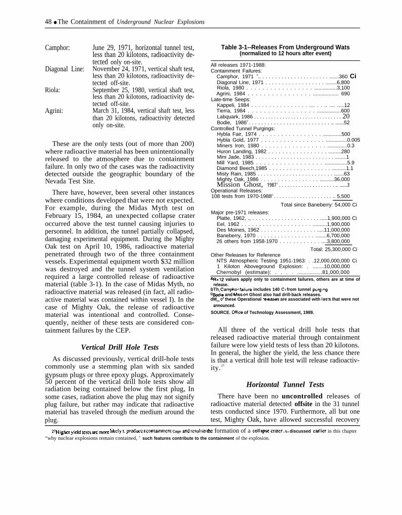
48 ● The Containment of Underground Nuclear Explosions
Camphor:
Diagonal Line:
Riola:
Agrini:
June 29, 1971, horizontal tunnel test,less than 20 kilotons, radioactivity de-tected only on-site.November 24, 1971, vertical shaft test,less than 20 kilotons, radioactivity de-tected off-site.September 25, 1980, vertical shaft test,less than 20 kilotons, radioactivity de-tected off-site.March 31, 1984, vertical shaft test, lessthan 20 kilotons, radioactivity detectedonly on-site.
These are the only tests (out of more than 200)where radioactive material has been unintentionallyreleased to the atmosphere due to containmentfailure. In only two of the cases was the radioactivitydetected outside the geographic boundary of theNevada Test Site.
There have, however, been several other instanceswhere conditions developed that were not expected.For example, during the Midas Myth test onFebruary 15, 1984, an unexpected collapse crateroccurred above the test tunnel causing injuries topersonnel. In addition, the tunnel partially collapsed,damaging experimental equipment. During the MightyOak test on April 10, 1986, radioactive materialpenetrated through two of the three containmentvessels. Experimental equipment worth $32 millionwas destroyed and the tunnel system ventilationrequired a large controlled release of radioactivematerial (table 3-1). In the case of Midas Myth, noradioactive material was released (in fact, all radio-active material was contained within vessel I). In thecase of Mighty Oak, the release of radioactivematerial was intentional and controlled. Conse-quently, neither of these tests are considered con-tainment failures by the CEP.
Vertical Drill Hole Tests
As discussed previously, vertical drill-hole testscommonly use a stemming plan with six sandedgypsum plugs or three epoxy plugs. Approximately50 percent of the vertical drill hole tests show allradiation being contained below the first plug, Insome cases, radiation above the plug may not signifyplug failure, but rather may indicate that radioactivematerial has traveled through the medium around theplug.
Table 3-1--Releases From Underground Wats(normalized to 12 hours after event)
All releases 1971-1988:Containment Failures:
Camphor, 1971 b.. . . . . . . . . . . . . . . . . . . . . . .......360 CiDiagonal Line, 1971 . . . . . . . . . . . . . . . . . . ........6,800Riola, 1980 . . . . . . . . . . . . . . . . . ................3,100Agrini, 1984 . . . . . . . . . . . . . . . . .................. 690
Late-time Seeps:Kappeli, 1984 . . . . . . . . . . . . . . . . .... . . .. .... .....12Tierra, 1984 . . . . . . . . . . . . . . . . . .................600Labquark, 1986 . . . . . . . . . . . . . . . . . . . . . . . . . . . . . . . 20Bodie, 19863 . . . . . . . . . . . . . . . . . . . . . . . . . . .. ......52
Controlled Tunnel Purgings:Hybla Fair, 1974 . . . . . . . . . . . . . . . . . .............500Hybla Gold, 1977 . . . . . . . . . . . . . . . . . ...............0.005Miners Iron, 1980 . . . . . . . . . . . . . . . . . ..............0.3Huron Landing, 1982 . . . . . . . . . . . . . . . . . .........280Mini Jade, 1983 . . . . . . . . . . . . . . . . . . . . . . . . . ........1Mill Yard, 1985 . . . . . . . . . . . . . . . . . ................5.9Diamond Beech,1985 . . . . . . . . . . . . . . . . . . ..........1.1Misty Rain, 1985 . . . . . . . . . . . . . . . . . . . . . . . . .......63Mighty Oak, 1986 . . . . . . . . . . . . . . . . . ..........36,000Mission Ghost, 1987 C . . . . . . . . . . . . . . . . . . . . .. ......3
Operational Releases:108 tests from 1970-1988d . . . . . . . . . . . . . . . . . . . . .. 5,500
Total since Baneberry: 54,000 Ci
Major pre-1971 releases:Platte, 1962, ., . . . . . . . . . . . . . . . . . . . . . .....1,900,000 CiEel, 1962 . . . . . . . . . . . . . . . . . . . . ..........1,900,000Des Moines, 1962 . . . . . . . . . . . . . . . . . .....11,000,000Baneberry, 1970 . . . . . . . . . . . . . . . . . ........6,700,00026 others from 1958-1970 . . . . . . . . . . . . ....3,800,000
Total: 25,300,000 CiOther Releases for Reference
NTS Atmospheric Testing 1951-1963: . .12,000,000,000 Ci1 Kiloton Aboveground Explosion: . ........10,000,000Chernobyl (estimate): . . . . ................81,000,000
aR+12 values apply only to containment failures, others are at time ofrelease.
bThe camphor fatlure includes 140 CI from tunnel PLJr9in9.cBodie and Ms.slon Ghost also had drill-back releases.dMany of these Operational releases are associated with tests that were not
announced.
SOURCE. OffIce of Technology Assessment, 1989.
All three of the vertical drill hole tests thatreleased radioactive material through containmentfailure were low yield tests of less than 20 kilotons.In general, the higher the yield, the less chance thereis that a vertical drill hole test will release radioactiv-ity. 27
Horizontal Tunnel Tests
There have been no uncontrolled releases ofradioactive material detected offsite in the 31 tunneltests conducted since 1970. Furthermore, all but onetest, Mighty Oak, have allowed successful recovery
27H1@r yield te~t~ UC more ]ikc]y t. produ~c a c~n~ainrncnl Cage ~d result in the formation of a Co]lapse crater. AS discussed car]ier in this chapter“why nuclear explosions remain contained, ’ such features contribute to the containment of the explosion.
Chapter 3--Containing Underground Nuclear Explosions ● 49
of the experimental equipment. Mighty Oak andCamphor are the only tests where radioactivityescaped out of vessel II. In no test, other thanCamphor, has radioactive material escaped out ofvessel III. Camphor resulted in an uncontrolledrelease of radioactive material that was detectedonly on site.
There have been several instances when smallamounts of radioactivity were released intentionallyto the atmosphere through controlled purging. Inthese cases, the decision was made to vent the tunneland release the radioactivity so the experimentalresults and equipment could be recovered. Theevents that required such a controlled release are the10 tests where radioactive material escaped out ofvessel I and into vessel II, namely:
Hybla Fair, October 28, 1974.
Hybla Gold, November 1, 1977.
Miners Iron, October 31, 1980.
Huron Landing, September 23, 1982.
Mini Jade, May 26, 1983.
Mill Yard, October 9, 1985.
Diamond Beech, October 9,
Misty Rain, April 6, 1985.
1985.
Mighty Oak, April 10, 1986.
Mission Ghost, June 20, 198728
In most cases, the release was due to the failure ofsome part of the experiment protection system.
Table 3-1 includes every instance (for bothannounced and unannounced tests) where radioac-tive material has reached the atmosphere under anycircumstances whatsoever from 1971 through 1988.The lower part of table 3-1 summarizes undergroundtests prior to 1971 and provides a comparison withother releases of radioactive material.
Since 1970, 126 tests have resulted in radioactivematerial reaching the atmosphere with a total releaseof about 54,000 Curies. Of this amount, 11,500Ci were due to containment failure and late-timeseeps. The remaining 42,500 Ci were operationalreleases and controlled tunnel ventilations—withMighty Oak (36,000 Ci) as the main source. Section
3 of the table shows that the release of radioactivematerial from underground nuclear testing sinceBaneberry (54,000 Ci) is extremely small in compar-ison to the amount of material released by pre-Baneberry underground tests (25,300,000 Ci), theearly atmospheric tests at the Nevada Test Site, oreven the amount that would be released by al-kiloton explosion conducted above ground (l0,000,000Ci).
From the Perspective of Human Health Risk
If a single person had been standing at theboundary of the Nevada Test Site in the area ofmaximum concentration of radioactivity for everytest since Baneberry (1970), that person’s totalexposure would be equivalent to 32 extra minutesof normal background exposure (or the equiva-lent of 1/1000 of a single chest x-ray).
A FEW EXAMPLES:Although over 90 percent of all test explosions
occur as predicted, occasionally something goeswrong. In some cases, the failure results in the lossof experimental equipment or requires the controlledventilation of a tunnel system. In even more rarecases (less than 3 percent), the failure results in theunintentional release of radioactive material to theatmosphere. A look at examples shows situationswhere an unexpected sequence of events contributeto create an unpredicted situation (as occurred inBaneberry (see box 3-l)), and also situations wherethe full reason for containment failure still remainsa mystery.
1. Camphor (June 29, 1971, horizontal tunnel test,less than 20 kilotons, radioactivity detected onlyon-site, )
The ground shock produced by the Camphorexplosion failed to close the HLOS pipe fully. Afterabout 10 seconds, gases leaked through and erodedthe stemming plug. As gases flowed through thestemming plug, pressure increased on the closuredoor behind the experiment. Gases leaked aroundthe cable passage ways and eroded open a hole.Pressure was then placed on the final door, whichheld but leaked slightly. Prior to the test, thecontainment plan for Camphor received six ‘‘I’from the CEP.29
zs~e Mission Ghost rc]e~ was due to a post-shol drill hole.
290p. cit., footnote 20.

50 ● The Containment of Underground Nuclear Explosions
2. Diagonal Line (November 24, 1971, verticalshaft test, less than 20 kilotons, radioactivity de-tected off-site.)
In a sense, the Diagonal Line seep was predictedby the CEP. Prior to the test, Diagonal Line receivedall “A” categorizations, except from one memberwho gave it a‘ ‘B. ’ ’30 It was a conclusion of the panelthat due to the high CO2 content, a late-time (hoursor days after detonation) seepage was a highprobability. They did not believe, however, that thelevel of radiation would be high enough to bedetectable off-site. Permission to detonate wasrequested and granted because the test objectiveswere judged to outweigh the risk. Diagonal Line wasconducted in the northern part of Frenchman Flat. Itis speculated that carbonate material released CO2
gas that forced radioactive material to leak to thesurface. Diagonal Line was the last test detonated onFrenchman Flat.
3. Riola (September 25, 1980, vertical shaft test,less than 20 kilotons, radioactivity detected off-site.)
Ironically, Riola was originally proposed for adifferent location. The Containment EvaluationPanel, however, did not approve the first locationand so the test was moved. At its new location, Riolawas characterized by the CEP prior to the test with8 “A”s. Riola exploded with only a small fractionof the expected yield. A surface collapse occurredand the failure of a containment plug resulted in therelease of radioactive material.
4. Agrini (March 31, 1984, vertical shaft test, lessthan 20 kilotons, radioactivity detected only on-site. )
The Agrini explosion formed a deep subsidencecrater 60 feet west of the emplacement hole. A smallamount of radioactive material was pushed throughthe chimney by noncondensible gas pressure andwas detected onsite. The containment plan forAgrini received seven ‘‘A’ and two ‘B from theCEP prior to the test. The ‘‘B’*s were due to the useof a new stemming plan.
5. Midas Myth (February 15, 1984, horizontaltunnel test, less than 20 kilotons, no release ofradioactive material.)
All of the radioactive material produced by theMidas Myth test was contained within vessel I, withno release of radioactivity to either the atmosphereor the tunnel system. It is therefore not considered acontainment failure. Three hours after the test,however, the cavity collapsed and the chimneyreached the surface forming an unanticipated subsi-dence crater. Equipment trailers were damaged andpersonnel were injured (one person later died as aresult of complications from his injuries) when thecollapse crater formed.31 Analysis conducted afterthe test indicated that the formation of the collapsecrater should have been expected. Shots conductedon Yucca Flat with the same yield and at the samedepth of burial did, at times, produce surfacecollapse craters. In the case of Midas Myth, collapsewas not predicted because there had never been acollapse crater for a tunnel event and so the analysiswas not made prior to the accident. After analyzingthe test, the conclusion of the Surface SubsidenceReview Committee was:
That the crater is not an indication of someunusual, anomalous occurrence specific to the U12T.04emplacement site. Given the normal variation inexplosion phenomena, along with yield, depth ofburial, and geologic setting, experience indicates anappreciable chance for the formation of a surfacesubsidence crater for Midas Myth.
Prior to the test, the Containment EvaluationPanel characterized Midas Myth with nine “A”s.
6. Misty Rain ( April 6, 1985, horizontal tunneltest, less than 20 kilotons, no unintentional release ofradioactive material.)
Misty Rain is unusual in that it is the only tunneltest since 1970 that did not have three containmentvessels. In the Misty Rain test, the decision wasmade that because the tunnel system was so large, avessel II was not needed.32 Despite the lack of avessel II, the CEP categorized the containment ofMisty Rain with eight ‘A’ ‘s, and one ‘B. ’ ’33 Duringthe test, an early flow of energy down the HLOS pipeprevented the complete closure of the MAC doors.The MAC doors overlapped, but stopped a coupleinches short of full closure. The TAPS door closedonly 20 percent before the deformation from groundshock prevented it from closing. A small amount of
30~1d3
sl~e injuries were due to the physical circumstances of the collapse. There was no rSdit3t-iOtI tXpOStM’C.
sz~e ~fis in he tumel system created over 4 million cubic feet of open volume.lis~e ~ ~em~r did ~t i~[l~]y Categorize the test, ~terreceiving ~dition~ inf~ati~ concerning the test, he categorized the test with m ‘‘ A.
.
Chapter 3-Containing Underground Nuclear Explosions ● 51
radioactive material escaped down the pipe and thenseeped from the HLOS pipe tunnel into the bypasstunnel. Subsequently, the tunnel was intentionallyvented so that experimental equipment could berecovered.
7. Mighty Oak (April 10, 1986, horizontal tunneltest, less than 20 kilotons, no unintentional release ofradioactive material.)
During the Mighty Oak test, the closure systemnear the working point was over-pressured andfailed. The escaped pressure and temperature causedboth the MAC and the GSAC to fail. The loss of thestemming plug near the working point left the tunnelan open pathway from the cavity. Temperatures andpressures on the closed TAPS door reached 2,000“Fand 1,400 pounds per square inch. After 50 seconds,the center part (approximately 6 feet in diameter) ofthe TAPS door broke through. With the closuresremoved, the stemming column squeezed outthrough the tunnel. Radioactive material leakedfrom vessel I, into vessel II, and into vessel III, whereit was successfully contained. Approximately 85percent of the data from the prime test objectives wasrecovered, although about $32 million of normallyrecoverable and reusable equipment was lost.34
Controlled purging of the tunnel began 12 days afterthe test and continued intermittently from April 22to May 19, when weather conditions were favorable.A total of 36,000 Ci were released to the atmosphereduring this period.
IS THERE A REAL ESTATEPROBLEM AT NTS?
There have been over 600 underground and 100aboveground nuclear test explosions at the NevadaTest Site. With testing continuing at a rate of abouta dozen tests a year, the question of whether therewill eventually be no more room to test has beenraised. While such a concern may be justified for themost convenient areas under the simplest arrange-ments, it is not justified for the test area in general.Using the drill-hole spacing of approximately one-half the depth of burial, high-yield tests can bespaced about 1,000 feet apart, and low-yield testscan be spaced at distances of a few hundred feet.Consequently, a suitable square mile of test site mayprovide space for up to 25 high-yield tests or over
300 low-yield tests. Even with testing occurring at arate of 12 tests a year, the 1,350 square miles of testsite provide considerable space suitable for testing.
In recent years, attempts have been made to usespace more economically, so that the most conven-ient locations will remain available. Tests havetraditionally been spaced in only 2-dimensions. Itmay be possible to space tests 3-dimensionally, thatis, with testing located below or above earlier tests.Additionally, the test spacing has been mostly forconvenience. If available testing areas becomescarce, it may become possible to test at closerspacing, or even to test at the same location as aprevious test.
Area for horizontal tunnel tests will also beavailable for the future. The N-tunnel area has beenextended and has a sizable area for future testing.P-tunnel, which is used for low-yield effects tests,has only been started. (See figure 2-4 inch. 2 of thisreport.) Within Rainier and Aqueduct Mesa alone,there is enough area to continue tunnel tests at a rateof two a year for at least the next 30 years.Consequently, lack of adequate real estate will notbe a problem for nuclear testing for at least severalmore decades.
TIRED MOUNTAIN SYNDROME?The “Tired Mountain Syndrome” hypothesis
postulates that repeated testing in Rainier Mesa hascreated a “tired” mountain that no longer has thestrength to contain future tests. Support for thisconcern has come from the observation of cracks inthe ground on top of the Mesa and from seismologi-cal measurements, indicating that large volumes ofrock lose strength during an underground test.Debate exists, however, over both the inference thatthe weakened rock is a danger to containment, andthe premise that large volumes of rock are beingweakened by nuclear testing.
Basic to the concern over tired mountain syn-drome is the assumption that weakened rock willadversely affect containment. As discussed previ-ously, only in an extreme situation, such as detonat-ing an explosion in water-saturated clay, would rockstrength be a factor in contributing to a leak ofradioactive material. 35 For example, many tests have
34CoWa1menta~S@V Revlewfor [he ~igh~ oak N~le~r we~on Eflects Test, us, Dep~men( of Energy, Nevada Opcra[iorls Office, NVO-3 ] 1,May 1, 1987.
~sSee earlier section “Why do nuclear tests remain contained?”

52 ● The Containment of Underground Nuclear Explosions
Photo credit: Department of Energy
Fracture on Rainier Mesa.
been detonated in alluvial deposits, which areessentially big piles of sediment with nearly nointernal strength in an unconfined state. Despite theweakness and lack of cohesiveness of the material,such explosions remain well contained.
Compared to vertical drill hole tests, tunnel testsare overburied and conservatively spaced. Thetunnel system in Rainier Mesa is at a depth of 1,300feet. By the standards for vertical drill hole tests(using the scaled depth formula36), this is deepenough to test at yields of up to 34 kilotons; and yetall tunnel tests are less than 20 kilotons.37 Conse-quently, all tunnel tests in Rainier Mesa are buriedat depths comparatively greater than vertical drillhole tests on Yucca Flat. Furthermore, the minimumseparation distance of tunnel shots (twice the com-bined cavity radii plus 100 feet) results in a greaterseparation distance than the minimum separation
distance of vertical drill hole shots (1/2 depth ofburial) for tests of the same yield (compare figures3-2 and 3-3). Consequently, neither materialstrength, burial depth, nor separation distancewould make leakage to the surface more likely fora tunnel test on Rainier Mesa than for a verticaldrill hole tests on Yucca Flat.
Despite the relative lack of importance of strengthin preventing possible leakage to the surface, thevolume of material weakened or fractured by anexplosion is of interest because it could affect theperformance of the tunnel closures and possibleleakage of cavity gas to the tunnel complex. Disputeover the amount of rock fractured by an undergroundnuclear explosion stems from the following two,seemingly contradictory, but in fact consistentobservations:
1. Post-shot measurements of rock samples takenfrom the tunnel complex generally show no changein the properties of the rock at a distance greater than3 cavity radii from the point of the explosion. Thisobservation implies that rock strength is measurablydecreased only within the small volume of radius =165 (yield) 1/3,38 where the radius is measured in feetfrom the point of the explosion and the yield ismeasured in kilotons (figure 3-10).
2. Seismic recordings of underground explosionsat Rainier Mesa include signals that indicate the lossof strength in a volume of rock whose radius isslightly larger than the scaled depth of burial. Thisobservation implies that the rock strength is de-creased throughout the large volume of radius = 500(yield)1/3, where the radius is measured in feet fromthe point of the explosion and the yield is measuredin kilotons (figure 3-11). The loss of strength in alarge volume seems to be further supported bycracks in the ground at the top of Rainier Mesa thatwere created by nuclear tests.
The first observation is based on tests of samplesobtained from drilling back into the rock surround-ing the tunnel complex after a test explosion, Thecore samples contain microfractures out to a distancefrom the shot point equal to two cavity radii.Although microfractures are not seen past two cavityradii, measurements of seismic shear velocities
sbDep~(fi) = 400” (yield(kt))lfl
37’ ‘Announced United States Nuclear 7ksts, July 1945 through December 1987,’ United States Lkpartment of Energy, NVO-209 (Rcv.8), April, 1988.
381f tie ~~w of a ~avlty prod~~d by ~ exp]oslon is equ~ to 55 (y]e]d)l~, a dlst~cc of ~~ cavity r~li would & equal [O lhrw tirncs (his, or 165(yield)]fl.
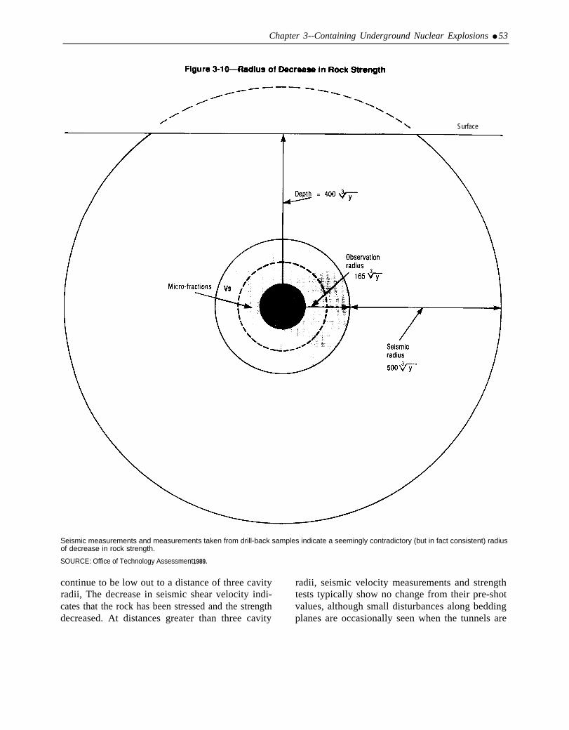
Chapter 3--Containing Underground Nuclear Explosions ● 53
Surface
Seismic measurements and measurements taken from drill-back samples indicate a seemingly contradictory (but in fact consistent) radiusof decrease in rock strength.
SOURCE: Office of Technology Assessment, 1989.
continue to be low out to a distance of three cavity radii, seismic velocity measurements and strengthradii, The decrease in seismic shear velocity indi- tests typically show no change from their pre-shotcates that the rock has been stressed and the strength values, although small disturbances along beddingdecreased. At distances greater than three cavity planes are occasionally seen when the tunnels are

54 ● The Containment of Underground Nuclear Explosions
recentered after the test. Such measurements suggestthat the explosion only affects rock strength to adistance from the shot point to about three cavityradii (165 (yield) 113).
The second observation, obtained from seismicmeasurements of tectonic release, suggests a largerradius for the volume of rock affected by anexplosion. The seismic signals from undergroundnuclear explosions frequently contain signals cre-ated by what is called “tectonic release. ” Byfracturing the rock, the explosion releases anypreexisting natural stress that was locked within therock. The release of the stress is similar to a smallearthquake. The tectonic release observed in theseismic recordings of underground explosions fromRainier Mesa indicate the loss of strength in avolume of rock with a minimum radius equal to 500(yield)1/3.
Although the drill samples and the seismic dataappear to contradict each other, the followingexplanation appears to account for both: The force ofthe explosion creates a cavity and fractures rock outto the distance of 2 cavity radii from the shot point.Out to 3 cavity radii, existing cracks are extendedand connected, resulting in a decrease in seismicshear velocity. Outside 3 cavity radii, no new cracksform. At this distance, existing cracks are openedand strength is reduced, but only temporarily. Theopen cracks close immediately after the shock wavepasses due to the pressure exerted by the overlyingrock. Because the cracks close and no new cracks areformed, the rock properties are not changed. Post-shot tests of seismic shear velocity and strength arethe same as pre-shot measurements. This is consis-tent with both the observations of surface fracturesand the slight disturbances seen along beddingplanes at distances greater than 3 cavity radii. Thesurface fractures are due to surface span, whichwould indicate that the rock was overloaded by theshock wave. The disturbances of the bedding planeswould indicate that fractures are being opened out togreater distances than 3 cavity radii. In fact, thebedding plane disturbances are seen out to a distanceof 600 (yield)1/3, which is consistent with the radiusdetermined from tectonic release.
The large radius of weak rock derived fromtectonic release measurements represents the tran-sient weakening from the shot. The small radius of
weak rock derived from the post-shot tests repre-sents the volume where the rock properties havebeen permanently changed. From the point of viewof the integrity of the tunnel system, it is the smallerarea where the rock properties have been perma-nently changed (radius = 165 (yield)1/3) that shouldbe considered for containment. Because the line-of-sight tunnel is located so that the stemming plugregion and closures are outside the region ofpermanently weakened or fractured material, theclosure system is not degraded.
HOW SAFE IS SAFE ENOUGH?Every nuclear test is designed to be contained and
is reviewed for containment. In each step of the testprocedure there is built-in redundancy and conserva-tism. Every attempt is made to keep the chance ofcontainment failure as remote as possible. Thisconservatism and redundancy is essential, however;because no matter how perfect the process may be,it operates in an imperfect setting. For each test, thecontainment analysis is based on samples, estimates,and models that can only simplify and (at best)approximate the real complexities of the Earth. As aresult, predictions about containment depend largelyon judgments developed from past experience. Mostof what is known to cause problems-carbonatematerial, water, faults, scarps, clays, etc.—waslearned through experience. To withstand the conse-quences of a possible surprise, redundancy andconservatism is a requirement not an extravagance.Consequently, all efforts undertaken to ensure a safetesting program are necessary, and they must con-tinue to be vigorously pursued.
Deciding whether the testing program is saferequires a judgement of how safe is safe enough. Thesubjective nature of this judgement is illustratedthrough the decision-making process of the CEP,which reviews and assesses the containment of eachtest.39 They evaluate whether a test will be containedusing the categorizations of ‘‘high confidence, ’‘‘adequate degree of confidence, and some doubt.But, the CEP has no guidelines that attempt toquantify or describe in probabilistic terms whatconstitutes for example, an ‘‘adequate degree ofconfidence. Obviously one can never have 100percent confidence that a test will not releaseradioactive material. Whether “adequate confi-
Wm Conttiment Ev~uatlon pine} is a ~oup of rcpre=ntatlves from vfious Iakratories and technicat consulting organizations who evaluate theproposed containment plan for each test without regard to cost or other outside considerations (see ch. 2 for a complete discussion).

Chapter 3--Containing Underground Nuclear Explosions . 55
dence” translates into a chance of 1 in 100, 1 in1,000, or 1 in 1,000,000, requires a decision aboutwhat is an acceptable risk level. In turn, decisions ofacceptable risk level can only be made by weighingthe costs of an unintentional release against thebenefits of testing. Consequently, those who feelthat testing is important for our national security willaccept greater risk, and those who oppose nucleartesting will find even small risks unacceptable.
Establishing an acceptable level of risk is difficultnot only because of value judgments associated withnuclear testing, but also because the risk is not seenas voluntary to those outside the testing program.Much higher risks associated with voluntary, every-day activities may be acceptable even though themuch lower risks associated with the nuclear test sitemay still be considered unacceptable.
The question of whether the testing program is‘‘safe enough’ will ultimately remain a value
judgment that weighs the importance of testingagainst the risk to health and environment. In thissense, concern about safety will continue, largelyfueled by concern about the nuclear testing programitself. However, given the continuance of testing andthe acceptance of the associated environmentaldamage, the question of ‘adequate safety’ becomesreplaced with the less subjective question of whetherany improvements can be made to reduce thechances of an accidental release, In this regard, noareas for improvement have been identified. This isnot to say that future improvements will not be madeas experience increases, but only that essentially allsuggestions that increase the safety margin havebeen implemented. The safeguards built into eachtest make the chances of an accidental release ofradioactive material as remote as possible.
Chapter 4
Monitoring AccidentalRadiation Releases

CONTENTSPage
INTRODUCTION .. .. .. .. .. .. .. .. . ... ... ..... .. .. .. .. .. .. .. 59WHAT IS RADIATION? . . . . . . . . . . . . . . . . . . . . . . . . . . . . . .. .. .. .. . 59PRODUCTS OF A NUCLEAR EXPLOSION . . . . . . . . . . . . . . . . . . . . . . . . . . . . . . . . . . . . . . 59CRITERIA FOR CONDUCTING A TEST .. .. . . . . . . . . . . . . . . . . . . . . . . . . . . . . . . . . . . . 60PREDICTING FALLOUT PATTERNS .. .. .. .. .. .. .. .. ... ... ...... . . . . . . . . . . . . . 63ACCIDENT NOTIFICATION .. ........................... . . . . . . . . . . . . . . . . . . . . . 64
Onsite Monitoring by The Department of Energy .. .. .. .. .. .. .. ... .. . . . . . . . . . . . . . . 65Offsite Monitoring by The Environmental Protection Agency . . . . . . . . . . . . . . . . . . . . . . 66
GROUNDWATER . . . . . . . . . . . . . . . . . . . . . . . . . . . . . . . .. .. .. .. .. .. .. . . . . . . . . . . . . . . . . . 70MONITORING CAPABILITY . . . . . . . . . . . . . . . . . . . . . . . . . . . . . . . . . . . . . . . . . . . . . . . . . . . . . 74
FiguresFigure Page
4-1. The Typical Bimodal Curve for Fission-Product Yield . . . . . . . . . . . . . . . . . . . . . . . . . 604-2. Controllable and Uncontrollable Areas . . . . . . . . . . . . . . . . . . . . . . . . . . . . . . . . . . . . . . . . . 624-3. Projected Fallout Dispersion pattern . . . . . . . . . . . . . . . . . . . . . . . . . . . . . . . . . . . . . . . . . . . 634-44-54-64-74-84-9
Yield v. Distance . . . . . . . . . . . . . . . . . . . . . . . . . . . . . . . . . . . . . . . . . . . . . . . . . . . . . . .... 64Typical RAMs Array for Vertical Drill-Hole Shot . . . . . . . . . . . . . . . . . . . . . . . . . . . . 66Typical RAMs Array for Tunnel Shot . . . . . . . . . . . . . . . . . . . . . . . . . . . . ... ... ......67Air Monitoring Stations .. . .. . . .. ....... . . . . . . . . . . . . . . . . . . . . . . . . . . . . . . . . . . ... 69Sample Press Release . . . . . . . . . . . . . . . . . . . . . . . . . . . . . . . . . . . . . . . . . . . . . . . . . . . .... 72Standby Air Surveillance Network Stations . . . . . . . . . . . . . . . . . . . . . . . . . . . . . . . . . . . . 73
4-10. Locations Monitored With Thermoluminescent Dosimeters . . . . . . . . . . . . . . . . . . . . . 744-11. Milk Sampling Locations . . . . . . . . . . . . . . . . . . ... . . . . . . . . . . . . . . . . . . . . . . . . . . . . . . . 754-12. Standby Milk Surveillance Network . . . . . . . . . . . . . . . . . . . . . . . . . . . . . . . . . . . . . . . . . . . 764-13. Collection Site for Animals Sampled in 1987 . . . . . . . . . . . . . . . . . . . . . . . . . . . . . . . . . . 774-14. Locations of Families in the Offsite Human Surveillance Program.. ... .. . . . . . . . 784-15. Well Sampling Locations Onsite .. ............... . . . . . . . . . . . . . . . . . . . . . . . . . . 794-16. Well Sampling Locations Offside . . . . . . . . . . . . . . . . . . . . . ... . . . . . . . . . . . . . . . . . . . . . 80
TablesTable Page4-1. Common Radionuclides Involved in a Nuclear Explosion . . . . . . . . . . . . . . . . . . . . . . . . 604-2. Summary of Onsite Environmental Monitoring Program . . . . . . . . . . . . . . . . . . . . . . . . . 684-3. Citizens Alert Water Sampling Program . . . . . . . . . . . . . . . . . . . . . . . . . . . . . . . . . . . . . . . . 78
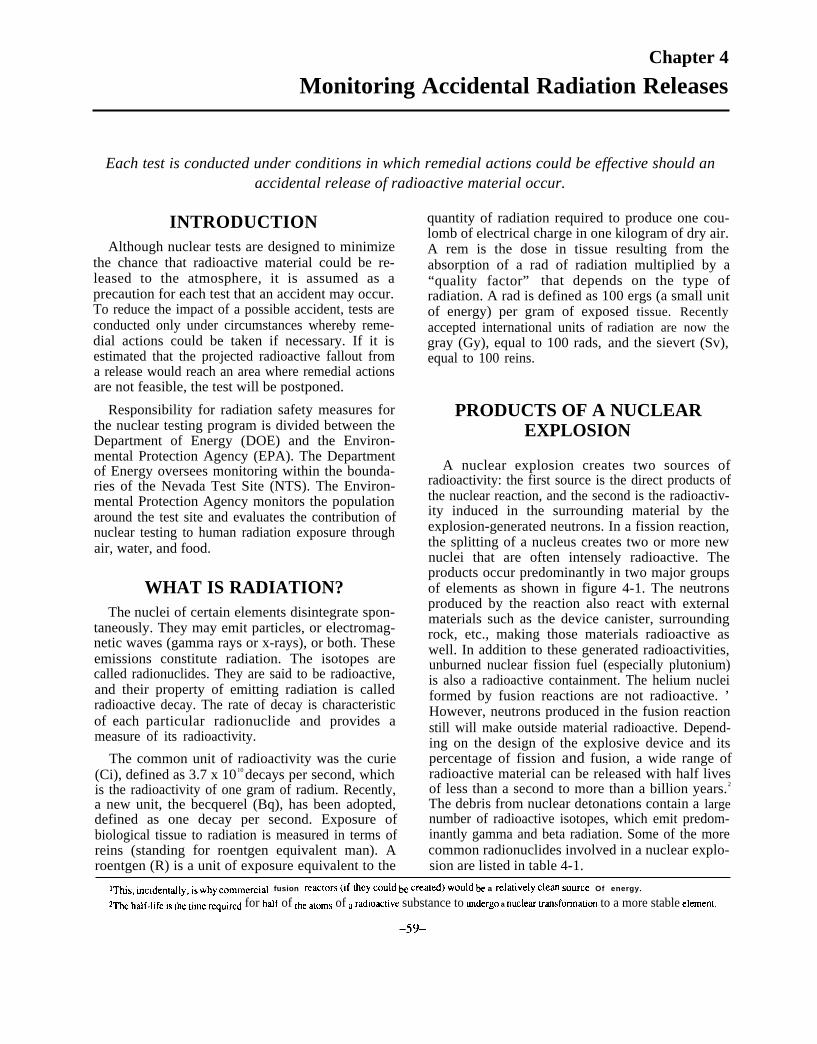
..
Chapter 4
Monitoring Accidental Radiation Releases
Each test is conducted under conditions in which remedial actions could be effective should anaccidental release of radioactive material occur.
INTRODUCTIONAlthough nuclear tests are designed to minimize
the chance that radioactive material could be re-leased to the atmosphere, it is assumed as aprecaution for each test that an accident may occur.To reduce the impact of a possible accident, tests areconducted only under circumstances whereby reme-dial actions could be taken if necessary. If it isestimated that the projected radioactive fallout froma release would reach an area where remedial actionsare not feasible, the test will be postponed.
Responsibility for radiation safety measures forthe nuclear testing program is divided between theDepartment of Energy (DOE) and the Environ-mental Protection Agency (EPA). The Departmentof Energy oversees monitoring within the bounda-ries of the Nevada Test Site (NTS). The Environ-mental Protection Agency monitors the populationaround the test site and evaluates the contribution ofnuclear testing to human radiation exposure throughair, water, and food.
WHAT IS RADIATION?The nuclei of certain elements disintegrate spon-
taneously. They may emit particles, or electromag-netic waves (gamma rays or x-rays), or both. Theseemissions constitute radiation. The isotopes arecalled radionuclides. They are said to be radioactive,and their property of emitting radiation is calledradioactive decay. The rate of decay is characteristicof each particular radionuclide and provides ameasure of its radioactivity.
The common unit of radioactivity was the curie(Ci), defined as 3.7 x 10¹⁰ decays per second, whichis the radioactivity of one gram of radium. Recently,a new unit, the becquerel (Bq), has been adopted,defined as one decay per second. Exposure ofbiological tissue to radiation is measured in terms ofreins (standing for roentgen equivalent man). Aroentgen (R) is a unit of exposure equivalent to the
quantity of radiation required to produce one cou-lomb of electrical charge in one kilogram of dry air.A rem is the dose in tissue resulting from theabsorption of a rad of radiation multiplied by a“quality factor” that depends on the type ofradiation. A rad is defined as 100 ergs (a small unitof energy) per gram of exposed tissue. Recentlyaccepted international units ofgray (Gy), equal to 100 rads,equal to 100 reins.
radiation are now theand the sievert (Sv),
PRODUCTS OF A NUCLEAREXPLOSION
A nuclear explosion creates two sources ofradioactivity: the first source is the direct products ofthe nuclear reaction, and the second is the radioactiv-ity induced in the surrounding material by theexplosion-generated neutrons. In a fission reaction,the splitting of a nucleus creates two or more newnuclei that are often intensely radioactive. Theproducts occur predominantly in two major groupsof elements as shown in figure 4-1. The neutronsproduced by the reaction also react with externalmaterials such as the device canister, surroundingrock, etc., making those materials radioactive aswell. In addition to these generated radioactivities,unburned nuclear fission fuel (especially plutonium)is also a radioactive containment. The helium nucleiformed by fusion reactions are not radioactive. ’However, neutrons produced in the fusion reactionstill will make outside material radioactive. Depend-ing on the design of the explosive device and itspercentage of fission and fusion, a wide range ofradioactive material can be released with half livesof less than a second to more than a billion years.2
The debris from nuclear detonations contain a largenumber of radioactive isotopes, which emit predom-inantly gamma and beta radiation. Some of the morecommon radionuclides involved in a nuclear explo-sion are listed in table 4-1.
IThls, incldent~]y, is why ~ommercla] fusion reac[ors (If ficy Coukj ~ created) Wou]d ~ a relatively clean SOurCe Of energy.
2~e h~f.]lfe is the time re~ulred for h~f of the aloms of a radioactive substance to undergo a nuclear ~ansformation to a more stable e]emenl.
-59-

60 ● The Containment of Underground Nuclear Explosions
Figure 4-1-The Typical Bimodal Curve forFission-Product Yield
Mass number
Products of a nuclear explosion occur predominantly in two majorgroups of nuclides.
SOURCE: Modified from Lapp and Andrews, Prentice-Hall, Inc., 1972.
An individual radioactive species follows thehalf-life rule of decay—that is, half of the nucleidisintegrate in a characteristic time. called a “half-life. ” However, a mixture of fission products has amore complicated decay pattern. The general rule ofthumb for a nuclear explosion is that the totalactivity decreases by a factor of 10 for everysevenfold increase in time. In other words, if thegamma radiation 1 hour after an explosion has anintensity of 100 units, then 7 hours later it will havean intensity of 10. Consequently. the time after theexplosion has a dramatic effect on the amount ofradioactivity. A 1 kiloton explosion in the atmos-phere will produce 41 billion curies 1 minute afterdetermination, but this will decrease to 10 millioncuries in just 12 hours.
Table 4-1--Common Radionuclides Involved in aNuclear Explosion
Radionuclide Half-Life
Uranium-238 . . . . . . . . . . . . . . . . . . . . . . . . .4,500,000,000 yearsPlutonium-239 . . . . . . . . . . . . . . . . . . . . . . . . . . . . . 24,300 yearsCarbon-14 . . . . . . . . . . . . . . . . . . . . . . ............5,800 yearsRadium-226 . . . . . . . . . . . . . . . . . . . . . . . . . . . . . . . . .1,620 yearsCesium-137 . . . . . . . . . . . . . . . . . . . . . . . . . . . . . . . . . . . 30 yearsStrontium-90 . . . . . . . . . . . . . . . . . . . . . . . . . . . . . . . . . . .28 yearsTritium . . . . . ., . . . . . . . . . . . . . . . . . . 12.3 yearsKrypton-85 . . . . . . . . . . . . . . . . . . . . . . . . . ; 10.9 yearsiodine-131 . . . . . . . . . . . . . . . . . . . . . . . . . . . . . . . . . . . . . . 8 daysXenon-133 . . . . . . . . . . . . . . . . . . . . . . . . . . . . . . . . . . . . 5.2 daysiodine-132 . . . . . . . . . . . . . . . . . . . . . ...............2.4 hours
The type of release is also important in predictingwhat radionuclides will be present. For example,atmospheric tests release all radionuclides created.Prompt, massive ventings have released a nonnegli-gible fraction of the radionuclides created. Late-time, minor seeps, like those since 1970, release onlythe most volatile radionuclides. In an undergroundexplosion, radionuclides also separate (called frac-tionation”) according to their chemical or physicalcharacteristics. Refractory particles (particles thatdo not vaporize during the nuclear explosion) settleout fast underground, while more volatile elementsthat vaporize easily condense later. This has a strongeffect on radioactive gases that seep slowly throughthe soil from an underground explosion. In anunderground explosion, nearly all the reactive mate-rials are filtered out through the soil column. and theonly elements that come up through the soil to theatmosphere are the noble gases, primarily kryptonand xenon.
CRITERIA
Although everyaccidental release
FOR CONDUCTINGA TEST
attempt is made to prevent theof radioactive material to the
atmosphere, several safety programs are carried outfor each test. These programs are designed tominimize the likelihood and extent of radiationexposure offsite and to reduce risks to people shouldan accidental release of radioactive material occur.The Environmental Protection Agency monitors thepopulation around the test site and has establishedplans to protect people should an accident occur.EPA’s preparations are aimed toward reducing thewhole-body exposure of the off-site populace and tominimizing thyroid dose to offsite residents, particu-

Chapter 3--Monitoring Accidental Radiation Releases ● 61
larly from the ingestion of contaminated milk.3 Thewhole-body dose is the main concern. However,deposition of radioactive material on pastures canlead to concentration in milk obtained from cowsthat graze on those pastures. The infant thyroid dosesfrom drinking milk from family cows is alsoassessed. 4
The Department of Energy’s criteria for conduct-ing a test are:
For tests at the Nevada Test Site, when consider-ing the event-day weather conditions and the specificevent characteristics, calculations should be madeusing the most appropriate hypothetical releasemodels which estimate the off-site exposures thatcould result from the most probable release scenario.Should such estimates indicate that off-site popula-tions, in areas where remedial actions to reducewhole-body exposures are not feasible, could receiveaverage whole-body dose in excess of 0.17 R/year(170 mR/year), the event shall be postponed untilmore favorable conditions prevail. In addition,events may proceed only where remedial actionsagainst uptake of radionuclides in the food chain arepracticable and/or indications are that average thy-roid doses to the population will not exceed 0.5R/year (500 mR/year).5
These criteria mean that a test can only take placeif the estimate of the fallout from an accidentalrelease of radioactivity would not be greater than0.17 R/year in areas that are uncontrollable, i.e.,where ‘‘remedial actions to reduce whole-bodyexposures are not feasible. ” Thus, tests are notconducted when the wind is blowing in the generaldirection of populated areas considered to be uncon-trollable, except under persistent light wind condi-tions that would limit the significant fallout to theimmediate vicinity of the NTS. Areas considered tobe uncontrollable by EPA are shown in figure 4-2.
The EPA and DOE have also defined a controlla-ble area (figure 4-2), within which remedial actionsare considered feasible. Criteria for the controllablearea, as defined by the DOE are:
. . . those areas where trained rad-safe monitors areavailable, where communications are effective (wherethe exposure of each individual can be documented),where people can be expected to comply with
recommended remedial actions, and where remedialactions against uptake of radionuclides in the foodchain are practicable.
The controllable area is the zone within approxi-mately 125 miles of the test control point (see figure4-2) for which EPA judges that its remedial actionswould be effective. Within this area, EPA has thecapability to track any release and perform remedialactions to reduce exposure, including sheltering orevacuation of all personnel (as needed); controllingaccess to the area; controlling livestock feedingpractices, i.e., providing feed rather than allowinggrazing; replacing milk; and controlling food andwater.
In the case of the controllable area, a test may beconducted if the fallout estimate implies that indi-viduals in the area would not receive whole-bodydoses in excess of 0.5 R/year and thyroid doses of 1.5R/year. If winds measured by the weather serviceindicate that the cloud of radioactive debris pro-duced by the assumed venting would drift overcontrollable areas, such as to the north, the test ispermitted when EPA’s mobile monitors are in thedownwind areas at populated places. EPA must beready to measure exposure and to assist in movingpeople under cover or evacuating them, if necessary,to keep their exposures below allowable levels.
As a consequence of the geometry of the control-lable area, tests are generally not conducted if windsaloft blow toward Las Vegas or towards other nearbypopulated locations. In addition, the test will not beconducted if there is less than 3 hours of daylightremaining to track the cloud.
Prior to conducting a test, detailed fallout projec-tions are made by the weather service for thecondition of “the unlikely event of a promptmassive venting. ” Predictions are made of theprojected fallout pattern and the maximum radiationexposures that might occur. An example of such aprediction is shown in figure 4-3. The center line isthe predicted path of maximum fallout depositionfor a prompt venting, marked with estimated arrivaltimes (in hours) at various distances. Lines to eitherside indicate the width of the fallout area. The twodashed lines indicate the 500 mR/year area and the
3Ses “Offsite Remediat Action Capability for Underground Nuclear Weapons lkst Accidents, ” U.S. Environmental Protection Agency,Environmental Monitoring Systems Laboratory--La.. Vegas, NV, October 1988.
d~ tie ~= of ~ ~ident, however, t~ ~tua] do= wo~d be minimized because the milk would ~ ~PkKed m much ~ Pssible.SS= ‘‘Offsite Reme.dia] &tion Capability for Underground Nuclear Weapons ‘kS1 Accidents, ’ U.S. Environmental Protection Agency,
Environmental Monitoring Systems Laboratory-Las Vegas, NV, October 1988.

62 The Containment of Underground Nuclear Explosions
Figure 4-2--Controllable and Uncontrollable Areas
The controllable area is the region within which remedial actions are considered feasible.
SOURCE. Modified from Enwronmental Protection Agency
170 mR/year level. If 0.17 mR/year (the maximum postponed. Within the predictions shown in figureexternal exposure allowed during a 12-month period 4-3, the test could be conducted if EPA monitorsfor an uncontrolled population) or more is predicted were prepared to be at each of the ranches, mines.to fall outside the controllable area, the test will be and other populated areas within the dispersion

Chapter 3--Monitoring Accidental Radiation Releases ● 63
Figure 4-3-Projected Fallout Dispersion Pattern
/
Glendale●
Key: H+ number= time of detonation plus elapsed hours; mR= milliREM
Predicted fallout pattern for the case of an accidental venting.
SOURCE Modlfled from. “Public Safety for Nuclear Weapons Tests,” U.S.Environmental Protection Agency, January 1984.
pattern to measure exposure and perform remedialactions should they be necessary.
The preferred weather conditions for a test are aclear sky for tracking, southerly winds (winds fromthe south), no thunderstorms or precipitation thatwould inhibit evacuation, and stable weather pat-terns. During the test preparations, the WeatherService Nuclear Support Office provides the TestController with predicted weather conditions. Thisinformation is used by the Weather Service to derivethe estimated fallout pattern should an accidentalrelease occur. About one-third of all nuclear tests aredelayed for weather considerations; the maximumdelay in recent years reached 16 days.
PREDICTING FALLOUTPATTERNS
The predicted fallout pattern from an undergroundtest depends on many variables related to the type ofnuclear device, the device’s material composition.type of venting, weather conditions, etc. With somany variables and so little experience with actualventings, fallout predictions can only be consideredapproximations. The accuracy of this approxima-tion, however, is critical to the decision of whethera test can be safely conducted. Fallout predictionsare made by the Weather Service Nuclear SupportOffice using up-to-date detailed weather forecastscombined with a model for a “prompt massiveventing. ” The model uses scaling technique basedon the actual venting of an underground test thatoccurred on March 13, 1964. The test, named“Pike,’ was a low-yield (less than 20 kilotons)explosion detonated in a vertical shaft. A massiveventing occurred 10 to 15 seconds after detonation.6
The venting continued for 69 seconds, at which timethe overburden rock collapsed forming a surfacesubsidence crater and blocking further venting. Thevented radioactive debris, consisting of gaseous andparticulate material, rose rapidly to about 3,000 feetabove the surface.
The Pike scaling model has been used to calculateestimates of fallout patterns for the past 20 yearsbecause: 1) the large amount of data collected fromthe Pike venting allowed the development of ascaling model, and 2) Pike is considered to be theworst venting in terms of potential exposure to thepublic.7
The Pike model, however, is based on a very smallrelease of radioactive material compared to whatwould be expected from an aboveground test of thesame size.8 The percentage of radioactive materialreleased from the Baneberry venting (7 percent fromtable 3-l), for example, is many times greater thanthe percentage of material released from the Piketest. 9 It would therefore appear that Baneberryprovides a more conservative model than Pike. This.however, is not the case because Baneberry was not
6PlkC ~U ~OndUC[~d in ~llUvl~ ,n ,L@~ s of’ the test site. The release Was ai~lbllied to a fr~~urc that propagated [0 tic surface. Other factor’icontributing to the release were an inadequate depth of burial and an inadequate closure of the line-of-sight pipe.
7“ 1985 Analyses and Evaluations of the Radiological and Meteorological Data from the Pike Event, ’ National Oceanic and At.mosphcrlcAdministration, Weather Service Nuclear Support Office, Las Vegas, NV, December, 1986, NVO-308.
gThe exact ~ount Of rnatcrial released from [he 1964 Pike test remains clmsified.gsec table 3-1 for a comparison of various rCICaSCS.
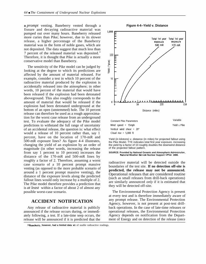
64 ● The Containment of Underground Nuclear Explosions
a prompt venting. Baneberry vented through afissure and decaying radioactive material waspumped out over many hours. Baneberry releasedmore curies than Pike; however, due to its slowerrelease, a higher percentage of the Baneberrymaterial was in the form of noble gases, which arenot deposited. The data suggest that much less than7 percent of the released material was deposited.10
Therefore, it is thought that Pike is actually a moreconservative model than Baneberry.
The sensitivity of the Pike model can be judged bylooking at the degree to which its predictions areaffected by the amount of material released. Forexample, consider a test in which 10 percent of theradioactive material produced by the explosion isaccidentally released into the atmosphere; in otherwords, 10 percent of the material that would havebeen released if the explosion had been detonatedaboveground. This also roughly corresponds to theamount of material that would be released if theexplosion had been detonated underground at thebottom of an open (unstemmed) hole. The 10 percentrelease can therefore be used as a rough approxima-tion for the worst case release from an undergroundtest. To evaluate the adequacy of the Pike modelpredictions to withstand the full range of uncertaintyof an accidental release, the question is: what effectwould a release of 10 percent rather than, say 1percent, have on the location of 170-mR and500-mR exposure lines? As figure 4-4 illustrates,changing the yield of an explosion by an order ofmagnitude (in other words, increasing the releasefrom say 1 percent to 10 percent) increases thedistance of the 170-mR and 500-mR lines byroughly a factor of 2. Therefore, assuming a worstcase scenario of a 10 percent prompt massiveventing (as opposed to the more probable scenario ofaround a 1 percent prompt massive venting), thedistance of the exposure levels along the predictedfallout lines would only increase by a multiple of 2.The Pike model therefore provides a prediction thatis at least within a factor of about 2 of almost anypossible worst-case scenario.
ACCIDENT NOTIFICATIONAny release of radioactive material is publicly
announced if the release occurs during, or immedi-ately following, a test. If a late-time seep occurs, therelease will be announced if it is predicted that the
1,000
100
10
0
Figure 4-4--Yield v. Distance
0 50 100 150
Distance (miles)
Constant Pike Parameters Variable
Wind speed = 15mph Yield x Pike
Vertical wind shear = 20°Cloud rise = 5,000 ft
Yield (in kilotons) v. distance (in miles) for projected fallout usingthe Pike Model. TYE indicates total first year exposure. increasingthe yield by a factor of 10 roughly doubles the downwind distanceof the projected fallout pattern.
SOURCE: Provided by National Oceanic and Atmospheric Admlnlstratlon,National Weather sarwee Nuclear Support Ofhee, 1888.
radioactive material will be detected outside theboundaries of the test site. If no detection off-site ispredicted, the release may not be announced.Operational releases that are considered routine(such as small releases from drill-back operations)are similarly announced only if it is estimated thatthey will be detected off-site.
The Environmental Protection Agency is presentat every test and is therefore immediately aware ofany prompt release. The Environmental ProtectionAgency, however, is not present at post-test drill-back operations. In the case of late-time releases oroperational releases, the Environmental ProtectionAgency depends on notification from the Depart-ment of Energy and on detection of the release (once
1OBmc&~, however, had a limited data WI of usable radioactive readings.

Chapter 4-Monitoring Accidental Radiation Releases ● 65
it has reached outside the borders of the test site) bythe EPA offsite monitoring system.
Estimates of whether a particular release will bedetected offsite are made by the Department ofEnergy or the sponsoring laboratory. Such judg-ments, however, are not always correct. During thedrill-back operations of the Glencoe test in 1986,minor levels of radioactive material were detectedoffsite contrary to expectations. During the Riolatest in 1980, minor amounts of radioactive inertgases were detected offsite. In both cases, DOEpersonnel did not anticipate the release to bedetected offsite and therefore did not notify EPA. l1
Although the releases were extremely minor andwell-monitored within the test site by DOE, EPAwas not aware of the release until the material hadcrossed the test site boundaries. Both cases fueledconcern over DOE’s willingness to announce acci-dents at the test site. The failure of DOE to publiclyannounce all releases, regardless of size or cir-cumstance, contributes to public concerns overthe secrecy of the testing program and reinforcesthe perceptions that all the dangers of the testingprogram are not being openly disclosed.
Onsite Monitoring by theDepartment of Energy
The Department of Energy has responsibility formonitoring within the boundaries of the Nevada TestSite to evaluate the containment of radioactivityonsite and to assess doses-to-man from radioactivereleases as a result of DOE operations. To achievethese objectives, DOE uses a comprehensive moni-toring system that includes both real-time monitor-ing equipment and sample recovery equipment. Thereal-time monitoring system is used for promptdetection following a test, the sample recoveryequipment is used to assess long-term dose and risk.
The heart of the real-time monitoring system is anetwork of Remote Area Monitors (RAMs). For alltests, RAMs are arranged in an array around the testhole (figure 4-5). Radiation detectors are alsofrequently installed down the stemming column sothe flow of radioactive material up the emplacementhole can be monitored. In tunnel shots, there areRAMs above the shot point, throughout the tunnelcomplex, outside the tunnel entrance, and in eachcontainment vessel (figure 4-6). In addition to
RAMs positioned for each shot, a permanent RAMnetwork with stations throughout the test site is incontinual operation.
During each test, a helicopter with closed-circuittelevision circles the ground zero location. Nearby.a second helicopter and an airplane are prepared totrack any release that might occur. A third helicopterand an airplane remain on stand-by should they beneeded. In addition, a team (called the ‘‘BluebirdTeam’ ‘), consisting of trained personnel in 2 four-wheel drive vehicles outfitted with detection equip-ment and personnel protection gear is stationed nearthe projected fallout area to track and monitor anyrelease. Approximately 50 radiation monitoringpersonnel are available on the Nevada Test Site tomake measurements of exposure rates and collectsamples for laboratory analysis should they beneeded. Prior to the test, portions of the test site areevacuated unless the operation requires mannedstations. If manned stations are required. directcommunication links are established with the work-ers and evacuation routes are set-up.
In addition to the real-time monitoring network,air and water samples are collected throughout theTest Site and analyzed at regular intervals. Thiscomprehensive environmental monitoring programis summarized in table 4-2. The network of samplerslocated throughout the Test Site includes 160thermoluminescent dosimeters; over 40 air samplersthat collect samples for analysis of radioiodines.gross beta, and plutonium-239: and about half adozen noble gas samplers. Each year over 4.500samples are collected and analyzed for radiologicalmeasurement and characterization of the NevadaTest Site, All sample collection, preparation, analy-sis, and review are performed by the staff of theLaboratory Operations Section of REECO’s Envi-ronmental Sciences Department.
In the case of a prompt, massive accidental releaseof radioactive material, the following emergencyprocedures would be initiated:
1. any remaining test site employees downwindof the release would be evacuated,
2. monitoring teams and radiological expertswould be dispatched to offsite downwindareas,
I I[n tie case of Rio]a, [he release ~currcd ]n the cvcnlng and was not reported until tic following morning, AS a resull, II was 12’/2 hours before EpAwas notified.
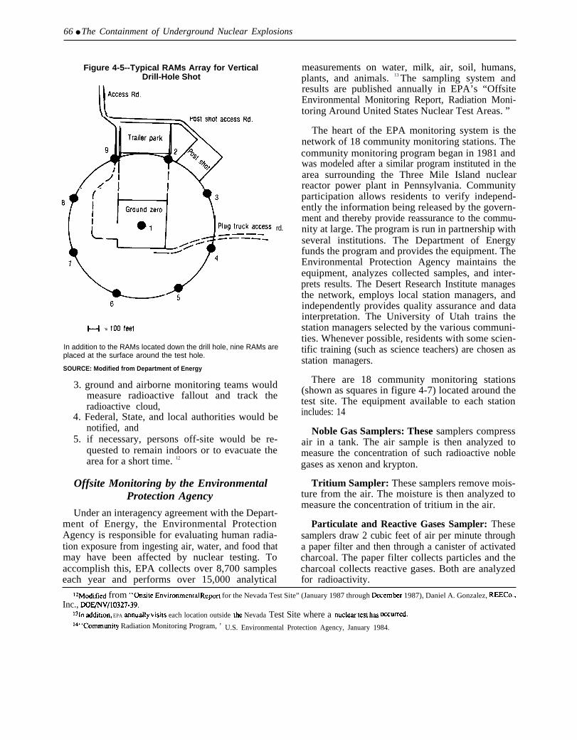
66 ● The Containment of Underground Nuclear Explosions
Figure 4-5--Typical RAMs Array for VerticalDrill-Hole Shot
rd.
In addition to the RAMs located down the drill hole, nine RAMs areplaced at the surface around the test hole.
SOURCE: Modified from Department of Energy
3. ground and airborne monitoring teams wouldmeasure radioactive fallout and track theradioactive cloud,
4. Federal, State, and local authorities would benotified, and
5. if necessary, persons off-site would be re-quested to remain indoors or to evacuate thearea for a short time. 12
Offsite Monitoring by the EnvironmentalProtection Agency
Under an interagency agreement with the Depart-ment of Energy, the Environmental ProtectionAgency is responsible for evaluating human radia-tion exposure from ingesting air, water, and food thatmay have been affected by nuclear testing. Toaccomplish this, EPA collects over 8,700 sampleseach year and performs over 15,000 analytical
measurements on water, milk, air, soil, humans,plants, and animals. 13 The sampling system andresults are published annually in EPA’s “OffsiteEnvironmental Monitoring Report, Radiation Moni-toring Around United States Nuclear Test Areas. ”
The heart of the EPA monitoring system is thenetwork of 18 community monitoring stations. Thecommunity monitoring program began in 1981 andwas modeled after a similar program instituted in thearea surrounding the Three Mile Island nuclearreactor power plant in Pennsylvania. Communityparticipation allows residents to verify independ-ently the information being released by the govern-ment and thereby provide reassurance to the commu-nity at large. The program is run in partnership withseveral institutions. The Department of Energyfunds the program and provides the equipment. TheEnvironmental Protection Agency maintains theequipment, analyzes collected samples, and inter-prets results. The Desert Research Institute managesthe network, employs local station managers, andindependently provides quality assurance and datainterpretation. The University of Utah trains thestation managers selected by the various communi-ties. Whenever possible, residents with some scien-tific training (such as science teachers) are chosen asstation managers.
There are 18 community monitoring stations(shown as squares in figure 4-7) located around thetest site. The equipment available to each stationincludes: 14
Noble Gas Samplers: These samplers compressair in a tank. The air sample is then analyzed tomeasure the concentration of such radioactive noblegases as xenon and krypton.
Tritium Sampler: These samplers remove mois-ture from the air. The moisture is then analyzed tomeasure the concentration of tritium in the air.
Particulate and Reactive Gases Sampler: Thesesamplers draw 2 cubic feet of air per minute througha paper filter and then through a canister of activatedcharcoal. The paper filter collects particles and thecharcoal collects reactive gases. Both are analyzedfor radioactivity.
lzM~ificd from “@site Environmcn[a] ReporI for the Nevada Test Site” (January 1987 through Deccmbcr 1987), Daniel A. Gonzalez, REECO.,Inc., DOEJNV/10327-39,
lsln addition, EPA annua]ly visi(s each location outside the Nevada Test Site where a nLICkW ttXt has @XunCd.
Id’’commwity Radiation Monitoring Program, ’ U.S. Environmental Protection Agency, January 1984.
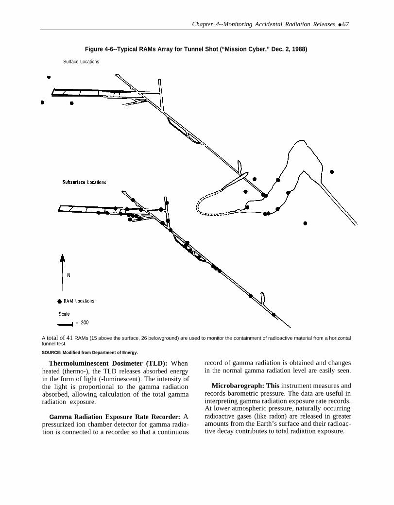
Chapter 4--Monitoring Accidental Radiation Releases ● 67
Figure 4-6--Typical RAMs Array for Tunnel Shot (“Mission Cyber,” Dec. 2, 1988)
Surface Locations
●
A total of 41 RAMs (15 above the surface, 26 belowground) are used to monitor the containment of radioactive material from a horizontaltunnel test.
SOURCE: Modified from Department of Energy.
Thermoluminescent Dosimeter (TLD): Whenheated (thermo-), the TLD releases absorbed energyin the form of light (-luminescent). The intensity ofthe light is proportional to the gamma radiationabsorbed, allowing calculation of the total gammaradiation exposure.
Gamma Radiation Exposure Rate Recorder: Apressurized ion chamber detector for gamma radia-tion is connected to a recorder so that a continuous
record of gamma radiation is obtained and changesin the normal gamma radiation level are easily seen.
Microbarograph: This instrument measures andrecords barometric pressure. The data are useful ininterpreting gamma radiation exposure rate records.At lower atmospheric pressure, naturally occurringradioactive gases (like radon) are released in greateramounts from the Earth’s surface and their radioac-tive decay contributes to total radiation exposure.
68 ● The Containmen of Underground Nuclear Explosions
Table 4-2-Summary of Onsite Environmental Monitoring Program
Collection NumberSample type Description frequency of locations Analysis
Air . . . . . . . . . . . . . . . . . . . . . Continuous sampling through Weekly 44 Gamma Spectroscopy gross beta, Pu-239gas filter & charcoal cartridgeLow-volume sampling through Biweekly 16 Tritium (HTO)silica gelContinuous low volume Weekly 7 Noble gases
Potable water . . . . . . . . . . . . 1-liter grab sample Weekly 7 Gamma Spectroscopy gross beta, tritium Pu-239 (quarterly)
Supply wells . . . . . . . . . . . . . l-liter grab sample Monthly 16 Gamma Spectroscopy gross beta, tritium Pu-239 (quarterly)
Open reservoirs . . . . . . . . . . l-liter grab sample Monthly 17* Gamma Spectroscopy gross beta, tritium Pu-239 (quarterly)
Natural springs . . . . . . . . . . . l-liter grab sample Monthly 9* Gamma Spectroscopy gross beta, tritium Pu-239 (quarterly)
Ponds (contaminated) . . . . . l-liter grab sample Monthly 8* Gamma Spectroscopy gross beta,tritium Pu-239 (quarterly)
Ponds (effluent) . . . . . . . . . . l-liter grab sample Monthly 5 Gamma Spectroscopy gross beta, tritium Pu-239 (quarterly)
External gamma radiationlevels . . . . . . . . . . . . . . . . . Thermoluminescent Semi- 1s3 Total integrated exposure over field cycle
Dosimeters annually
*Not all of these locations were sampled due to inaccessibility or lack of water.
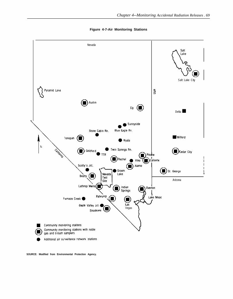
Chapter 4--Monitoring Accidental Radiation Releases . 69
Figure 4-7-Air Monitoring Stations
Nevada
Salt Lake City
e
Vegas)
1
Delta ■
III
Arizona
SOURCE: Modified from Environmental Protection Agency.
70 ● The Containment of underground Nuclear Explosions
The monitoring stations are extremely sensi-tive; they can detect changes in radiation exposuredue to changing weather conditions. For example,during periods of low atmospheric pressure, gammaexposure rates are elevated on the order of 2 to 4uR/hr because of the natural radioactive productsbeing drawn out of the ground. To inform the public,data from the community monitoring stations areposted at each station and sent to local newspapers(figure 4-8).
In addition to the 18 community monitoringstations, 13 other locations are used for the AirSurveillance Network (shown as circles in figure4-7) to monitor particulate and reactive gases. Theair surveillance network is designed to cover the areawithin 350 kilometers of the Nevada Test Site, witha concentration of stations in the prevailing down-wind direction. The air samplers draw air throughglass fiber filters to collect airborne particles (dust).Charcoal filters are placed behind the glass fiberfilters to collect reactive gases. These air samplersare operated continuously and samples are collectedthree times a week. The Air Surveillance Network issupplemented by 86 standby air sampling stationslocated in every State west of the Mississippi River(figure 4-9). These stations are ready for use asneeded and are operated by local individuals oragencies. Standby stations are used 1 to 2 weekseach quarter to maintain operational capability anddetect long-term trends.
Noble gas and tritium samplers are present at 17of the air monitoring stations (marked with asteriskin figure 4-7). The samplers are located at stationsclose to the test site and in areas of relatively lowaltitude where wind drains from the test site. Noblegases, like krypton and xenon, are nonreactive andare sampled by compressing air in pressure tanks.Tritium, which is the radioactive form of hydrogen,is reactive but occurs in the form of water vapor inair. It is sampled by trapping atmospheric moisture.The noble gas and tritium samplers are in continuousoperation and samples are recovered and analyzedweekly.
To monitor total radiation doses, a network ofapproximately 130 TLDs is operated by EPA. Thenetwork encircles the test site out to a distance ofabout 400 miles with somewhat of a concentration inthe zones of predicted fallout (figure 4-10). The TLDnetwork is designed to measure environmentalradiation exposures at a location rather than expo-
sures to a specific individual. By measuring expo-sures at fixed locations, it is possible to determinethe maximum exposure an individual would havereceived had he or she been continually present atthat location. In addition, about 50 people living nearthe test site and all personnel who work on the testsite wear TLD’s. All TLD’s are checked every 3months for absorbed radiation.
Radioactive material is deposited from the aironto pastures. Grazing cows concentrate certainradionuclides, such as iodine-131, strontium-90. andcesium-137 in their milk. The milk therefore be-comes a convenient and sensitive indicator of thefallout. The Environmental Protection Agency ana-lyzes samples of raw milk each month from about 25farms (both family farms and commercial dairies)surrounding the test site (figure 4-11 ). In addition tomonthly samples, a standby milk surveillance net-work of 120 Grade A milk producers in all Stateswest of the Mississippi River can provide samples incase of an accident (figure 4-12). Samples from thestandby network are collected annually.
Another potential exposure route of humans toradionuclides is through meat of local animals.Samples of muscle, lung, liver, kidney, blood. andbone are collected periodically from cattle pur-chased from commercial herds that graze northeastof the test site. In addition, samples of sheep, deer,horses, and other animals killed by hunters oraccidents are used (figure 4-1 3). Soft tissues areanalyzed for gamma-emitters. Bone and liver areanalyzed for strontium and plutonium; and blood/urine or soft tissue is analyzed for tritium.
A human surveillance program is also carried outto measure the levels of radioactive nuclides infamilies residing in communities and ranches aroundthe test site (figure 4-14). About 40 families livingnear the test site are analyzed twice a year. Awhole-body count of each person is made to assessthe presence of gamma-emitting radionuclides.
GROUNDWATERAbout 100 underground nuclear tests have been
conducted directly in the groundwater. In addition,many pathways exist for radioactive material fromother underground tests (tests either above or belowthe water table) to migrate from the test cavities tothe groundwater. To detect the migration of radioac-tivity from nuclear testing to potable water sources,a long-term hydrological monitoring program is

Chapter 4--Monitoring Accidental Radiation Releases . 71
Photo credit: David Graham, 1988
Whole Body Counter, Environmental Protection Agency.
managed by the Environmental Protection Agency elides from underground tests, DOE drilled a testat the Department of Energy’s direction with adviceon sampling locations being obtained from the U.S.Geological Survey. Whenever possible, water sam-ples are collected from wells downstream (in thedirection of movement of underground water) fromsites of nuclear detonations. On the Nevada TestSite, about 22 wells are sampled monthly (figure4-15). The 29 wells around the Nevada Test Site(figure 4-16) are also sampled monthly and analyzedfor tritium semiannually.
well near a nuclear weapons test named ‘‘Cambric.Cambric had a yield of 0.75 kilotons and wasdetonated in a vertical drill hole in 1965. A test wellwas drilled to a depth of 200 feet below the cavitycreated by Cambric. It was found that most of theradioactivity produced by the test was retainedwithin the fused rock formed by the explosion,although low concentrations of radioactive materialwere found in the water at the bottom of the cavity.A satellite well was also drilled 300 feet from the
The flow of groundwater through the Nevada Test cavity. More than 3 billion gallons of water were
Site is in a south-southwesterly direction. The flow pumped from the satellite well in an effort to drawspeed is estimated to be about 10 feet per year, water from the region of the nuclear explosion. Thealthough in some areas it may move as fast as 600 only radioactive materials found in the water werefeet per year. To study the migration of radionu- extremely small quantities (below the permitted
15SW ‘ 6 Radjonu~]jdc Migralion In Groundwtimr ~1 NTS, ” U.S. Depanmcnt of Energy, Septcmber, 1987.

—
72 ● The Containment of Underground Nuclear Explosions
Figure 4-8-Sample Press Release
Alamo, NV
COMMUNITY RADIATION MONITORING REPORT
Dell Sullivan, Manager of the Community Radiation Monitoring Station inAlamo, NV reported the results of the radiation measurements at this stationfor the period July 11 to July 20, 1988. The average gamma radiation exposurerate recorded by a Pressurized Ion Chamber at this station was 13.0microroentgens* per hour as shown on the chart.
AVERAGE GAMMA RADIATION EXPOSURE RATERECORDED ON THE PRESSURIZED ION CHAMBER ATALAMO, NV, DURING THE WEEK ENDING JULY 20, 1988
o 10 20 30Microroentgens Per Hour
The averages of the 16 Community Monitoring Stations operated for theEnvironmental Protection Agency, Department of Energy and the DesertResearch Institute varied from 6.2 microroentgens per hour at Las Vegas, NVto 20.2 microroentgens per hour at Austin, NV. All of the rates for the past weekwere within the normal background range for the United States as shown on theaccompanying chart. Environmental radiation exposure rates vary withaltitude and natural radioactivity in the soil. Additional information anddetailed data obtained from Community Radiation Monitoring NetworkStations, including an annual summary of the results from all monitoringaround the Nevada Test Site, can be obtained from Mr. Sullivan (702) 725-3544or by calling Charles F. Costa at the EPA in Las Vegas (702) 798-2305.
“The roent en is a measure of exposure to X or gamma radiation. A microroent en is 1f 5millionth o a roentgen. For comparison, one chest x-ray results in an exposure of 1 ,000 to
20,000 microroentgens.t Sum Of cosmic PIUS tefiestrial dose rates in air in the U.S.(PP3’7,42, BEIR ~~~, 1980).
Example of community radiation monitoring report that is posted at each monitoring station and sent to the press.
SOURCE. Environmental Protection Agency.

.—
Chapter 4--Monitoring Accidental Radiation Releases . 73
Figure 4-9-Standby Air Surveillance Network Stations
,
Scale in Miles
u ‘ \
Texas
100 300 500
86 standby air surveillance stations are available and samples are collected and analyzed every 3 months to maintain a data base.
SOURCE: Modified from Environmental Protection Agency,
level for drinking water) of krypton-85, chlorine-36,ruthenium-106, technetium-99 and iodine-1 29.
Radioactive material from nuclear testing movesthrough the groundwater at various rates and isfiltered by rock and sediment particles. Tritium,however, is an isotope of hydrogen and becomesincorporated in water molecules. As a result, tritiummoves at the same rate as groundwater. Tritium is
therefore the most mobile of the radioactive materi-als. Although tritium migrates, the short half-life oftritium (12.3 years) and slow movement of thegroundwater prevents it from reaching the Test Siteboundary. No analysis of groundwater has everfound tritium at a distance greater than a fewhundred meters from some of the old test sites. Noneof the water samples collected outside the bounda-

74 ● The Containment of Underground Nuclear Explosions
Figure 4-10-Locations Monitored With Thermoluminescent Dosimeters (TLDs)
Lake {
Tahoe
Arizona
One hundred thirty locations are monitored with TLDs. All TLDs are checked every 3 months for absorbed radiation.
SOURCE: Modified from Environmental Protection Agency.
ries of the test site has ever had detectable levels of groundwater contamination offsite of the Nevadaradioactivity attributable to the nuclear testing Test Site.program. An independent test of water samples fromaround the test site was conducted by Citizen Alert(Reno, Nevada) at 14 locations (table 4-3).
MONITORING CAPABILITYThe combination of: 1) the monitoring system
Citizen Alert found no detectable levels of tritium deployed for each test, 2) the onsite monitoringor fission products in any of their samples. With- system run by DOE, and 3) the offsite monitoringstanding any major change in the water table, there system run by EPA, forms a comprehensive detec-currently appears to be no problem associated with tion system for radioactive material. There is

Chapter Monitoring Accidental Radiation Releases ● 75
Figure 4-11-Milk Sampling Locations
o 50 100 150
Scale in Kilometers
John Deer ●●
●
Brent JonesDairy
● SF and K DairyI
Samples of raw milk are collected each month from about 25 farms surrounding the test site.
SOURCE’ Modified from Environmental ProtectIon Agency

76 ● The Containment of Underground Nuclear Explosions
Figure 4-12-Standby Milk Surveillance Network
All major milksheds west of the Mississippi River are part of the standby milk surveillance network.Samples are collected and analyzed annually.
SOURCE: Modfmd from Environmental Protection Agency
essentially no possibility that a significant releaseof radioactive material from an undergroundnuclear test could go undetected. Similarly, thereis essentially no chance that radioactive materialcould reach a pathway to humans and not bediscovered by the Environmental Protection Agency.Allegations that a release of radioactive materialcould escape from the test site undetected are basedon partial studies that only looked at a small portionof the total monitoring system. 16 Such criticisms areinvalid when assessed in terms of the total monitor-ing system.
The radiation monitoring system continues toimprove as new measurement systems and tech-niques become available and as health risks fromradiation become better understood. Assuming that
the monitoring effort will continue to evolve, andthat such issues as the migration of radioactivematerial in groundwater will continue to be aggres-sively addressed, there appear to be no valid criti-cisms associated with the containment of under-ground nuclear explosions. This is not to say thatfuture improvement will not be made as experienceincreases, but only that essentially all relevantsuggestions made to date that increase the safetymargin have been implemented.
Public confidence in the monitoring system suf-fers from a general lack of confidence in theDepartment of Energy that emanates from theenvironmental problems at nuclear weapons produc-tion facilities and from the radiation hazards associ-ated with past atmospheric tests. In the case of the
1%x for example, ‘‘A review of off-si[c cnvironmcrmd monitoring of tic Nevada Test Site,’ Bcmd Franke, Health Effcm of Underground NuclearTests, Oversight Hearing before the Subcomml[me on Energy and the Environment of the Committee on Interior and Insular Affairs, House ofRepre.senta[ives, Sep!. 25, 1987, Scr]al No. 1[)0-?5, pp. 120-144.

Chapter 4--Monitoring Accidental Radiation Releases ● 77
Figure 4-13-Collection Site for Animals Sampled In 1987
Bighorn Sheep
❑ Mule Deer
Nevada Test Site
Depending on availability, an assortment of animals are analyzed each year.
SOURCE Modified from Environmental Protection Agency.
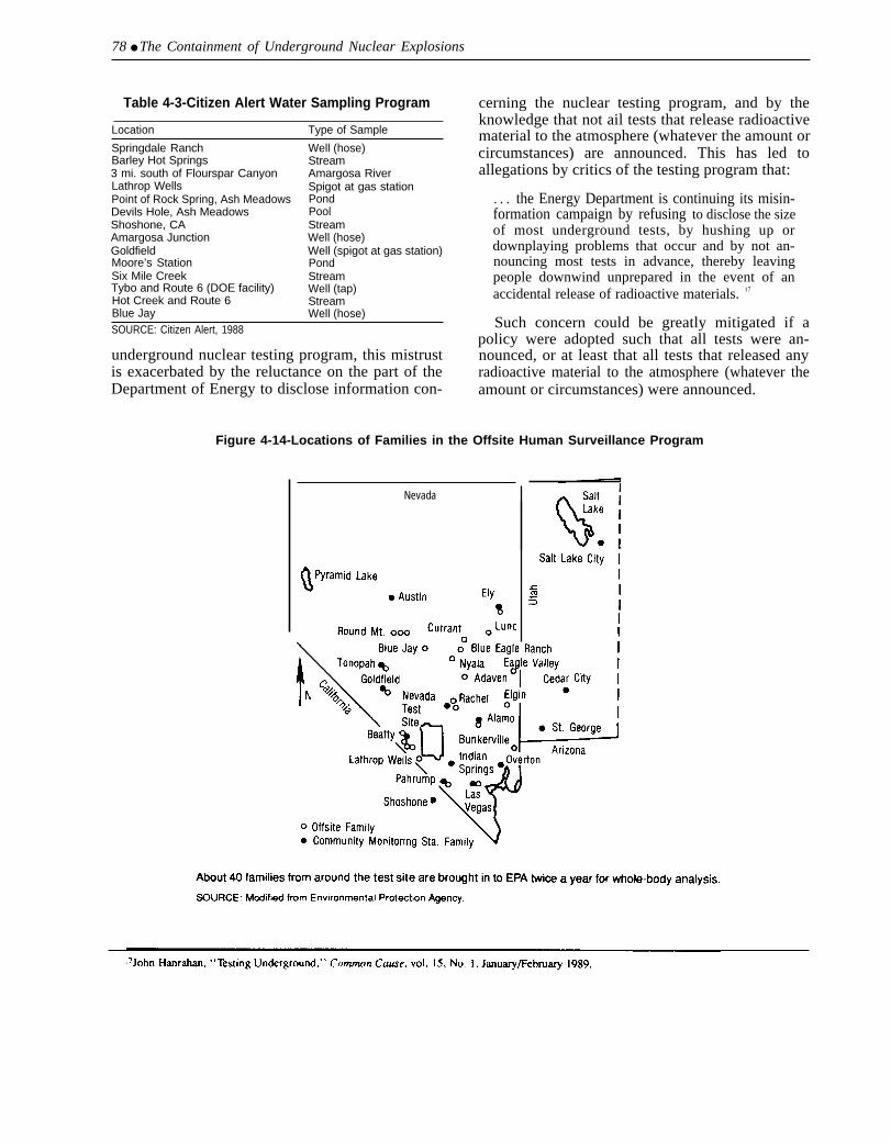
78 ● The Containment of Underground Nuclear Explosions
Table 4-3-Citizen Alert Water Sampling Program
Location Type of Sample
Springdale Ranch Well (hose)Barley Hot Springs Stream3 mi. south of Flourspar Canyon Amargosa RiverLathrop Wells Spigot at gas stationPoint of Rock Spring, Ash Meadows PondDevils Hole, Ash Meadows PoolShoshone, CA StreamAmargosa Junction Well (hose)Goldfield Well (spigot at gas station)Moore’s Station PondSix Mile Creek StreamTybo and Route 6 (DOE facility) Well (tap)Hot Creek and Route 6 StreamBlue Jay Well (hose)SOURCE: Citizen Alert, 1988
underground nuclear testing program, this mistrustis exacerbated by the reluctance on the part of theDepartment of Energy to disclose information con-
cerning the nuclear testing program, and by theknowledge that not ail tests that release radioactivematerial to the atmosphere (whatever the amount orcircumstances) are announced. This has led toallegations by critics of the testing program that:
. . . the Energy Department is continuing its misin-formation campaign by refusing to disclose the sizeof most underground tests, by hushing up ordownplaying problems that occur and by not an-nouncing most tests in advance, thereby leavingpeople downwind unprepared in the event of anaccidental release of radioactive materials. 17
Such concern could be greatly mitigated if apolicy were adopted such that all tests were an-nounced, or at least that all tests that released anyradioactive material to the atmosphere (whatever theamount or circumstances) were announced.
Figure 4-14-Locations of Families in the Offsite Human Surveillance Program
Nevada
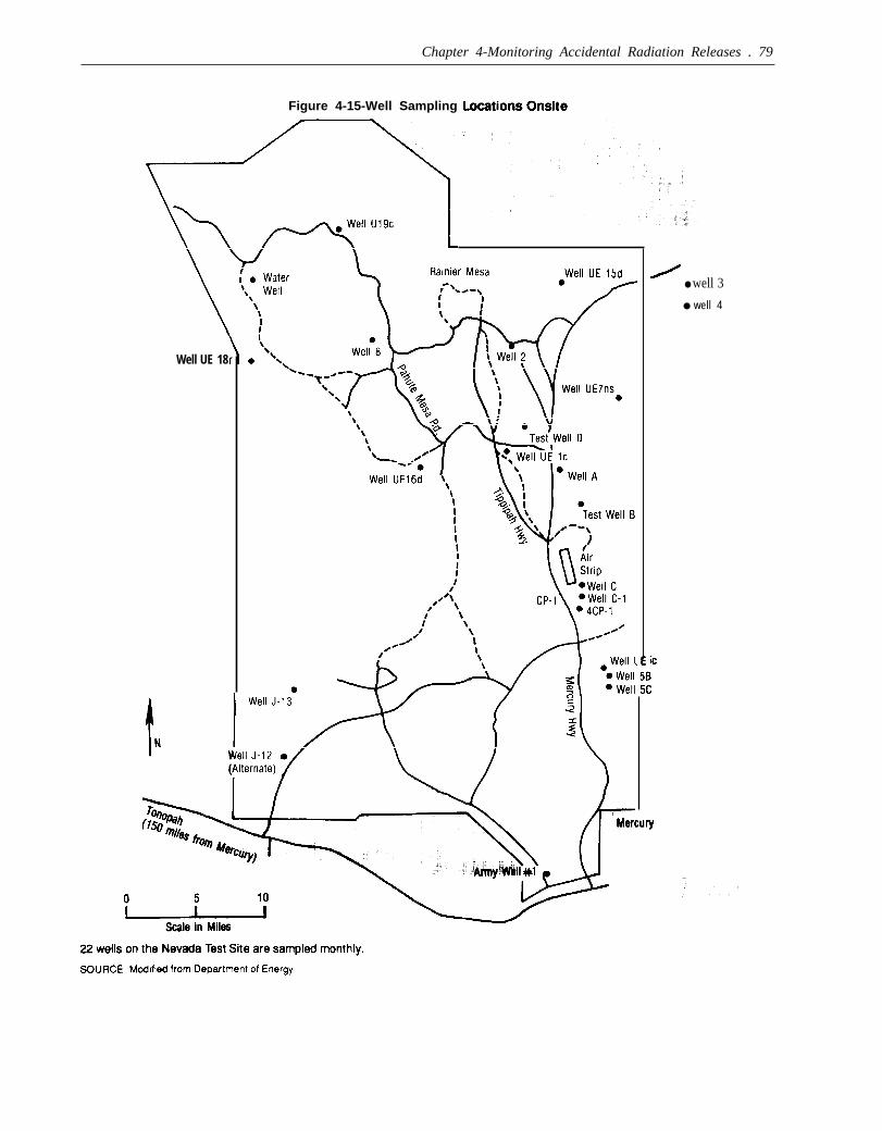
Chapter 4-Monitoring Accidental Radiation Releases . 79
Figure 4-15-Well Sampling
\
Well UE 18
● well 3
● well 4
ic
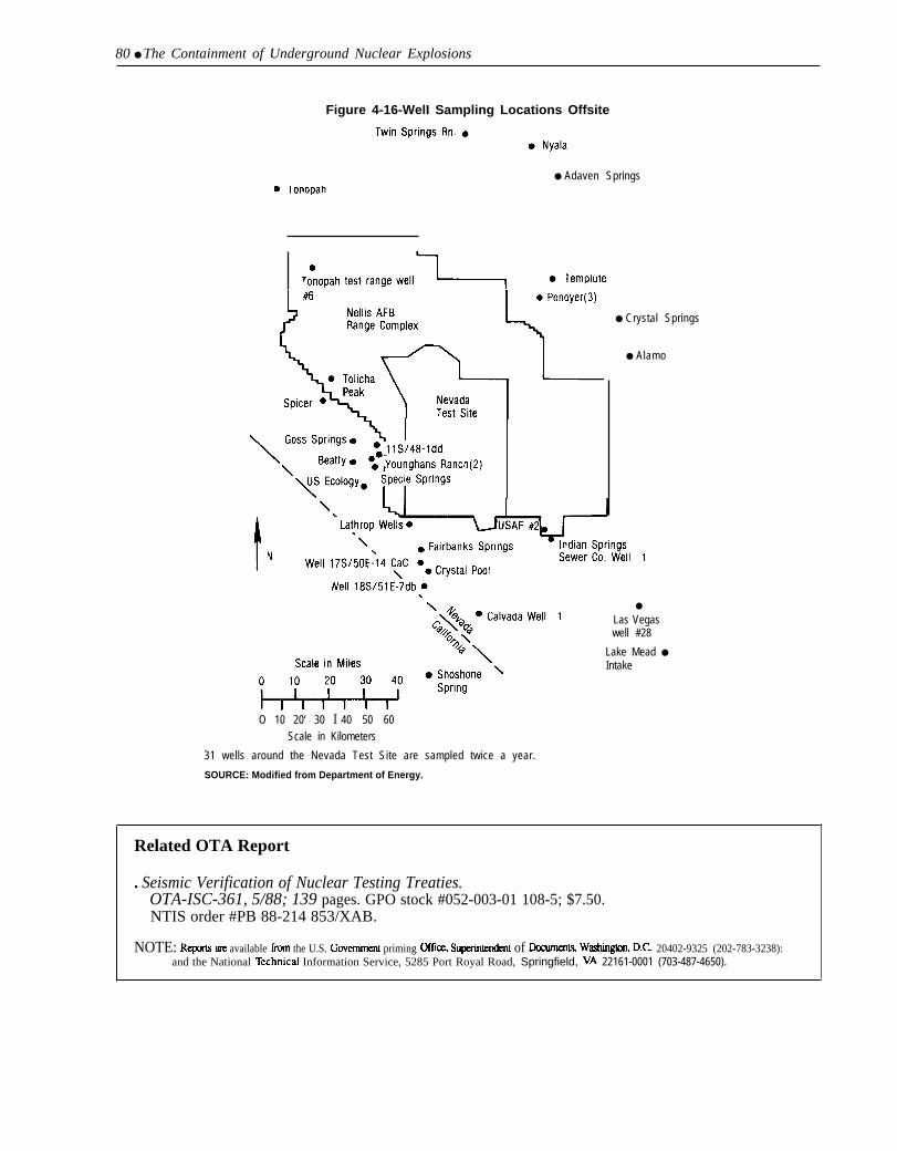
80 ● The Containment of Underground Nuclear Explosions
Figure 4-16-WelI Sampling Locations Offsite
● Adaven Springs
● Crystal Springs
● Alamo
O 10 20‘ 30 I 40 50 60Scale in Kilometers
31 wells around the Nevada Test Site are sampled twice a year.
SOURCE: Modified from Department of Energy.
●
Las Vegaswell #28
Lake Mead ●
Intake
Related OTA Report
. Seismic Verification of Nuclear Testing Treaties.OTA-ISC-361, 5/88; 139 pages. GPO stock #052-003-01 108-5; $7.50.NTIS order #PB 88-214 853/XAB.
NOTE: RepOm m available ilorn the U.S. Govemmcnt priming office, Supaintendent of Decurnent% Wash@on, D.C. 20402-9325 (202-783-3238):and the National lkchnical Information Service, 5285 Port Royal Road, Springfield, VA 22161-0001 (703-487-4650).