Embed Size (px)
Citation preview

ADNOC Classification: Internal
THE CONTENTS OF THIS DOCUMENT ARE PROPRIETARY.
ADNOC GROUP PROJECTS AND ENGINEERING ELECTRICAL ENGINEERING DESIGN GUIDE
Guideline
AGES-GL-02-001

ADNOC Classification: Internal
Document No: AGES-GL-02-001 Rev. No: 1 Page 2 of 91
ADNOC Classification: Internal
GROUP PROJECTS & ENGINEERING / PT&CS DIRECTORATE
CUSTODIAN Group Projects & Engineering / PT&CS ADNOC Specification applicable to ADNOC & ADNOC Group Companies
Group Projects & Engineering is the owner of this Specification and responsible for its custody, maintenance and periodic update.
In addition, Group Projects & Engineering is responsible for communication and distribution of any changes to this Specification and its version control.
This specification will be reviewed and updated in case of any changes affecting the activities described in this document.

Document No: AGES-GL-02-001 Rev. No: 1 Page 3 of 91
ADNOC Classification: Internal
INTER-RELATIONSHIPS AND STAKEHOLDERS
a) The following are inter-relationships for implementation of this Specification:
i. ADNOC Upstream and ADNOC Downstream Directorates and
ii. ADNOC Onshore, ADNOC Offshore, ADNOC Sour Gas, ADNOG Gas Processing. ADNOC LNG, ADNOC Refining, ADNOC Fertilisers, Borouge, Al Dhafra Petroleum, Al Yasat
b) The following are stakeholders for the purpose of this Specification:
ADNOC PT&CS Directorate.
c) This Specification has been approved by the ADNOC PT&CS is to be implemented by each ADNOC Group company included above subject to and in accordance with their Delegation of Authority and other governance-related processes in order to ensure compliance
d) Each ADNOC Group company must establish/nominate a Technical Authority responsible for compliance with
this Specification.
DEFINED TERMS / ABBREVIATIONS / REFERENCES
“ADNOC” means Abu Dhabi National Oil Company.
“ADNOC Group” means ADNOC together with each company in which ADNOC, directly or indirectly, controls fifty percent (50%) or more of the share capital.
“Approving Authority” means the decision-making body or employee with the required authority to approve Policies & Procedures or any changes to it.
“Business Line Directorates” or “BLD” means a directorate of ADNOC which is responsible for one or more Group Companies reporting to, or operating within the same line of business as, such directorate.
“Business Support Directorates and Functions” or “Non- BLD” means all the ADNOC functions and the remaining directorates, which are not ADNOC Business Line Directorates.
“CEO” means chief executive officer.
“Group Company” means any company within the ADNOC Group other than ADNOC.
“Guidelines” means this Electrical Engineering Design Guide
CONTROLLED INTRANET COPY
The intranet copy of this document located in the section under Group Policies on One ADNOC is the only controlled document. Copies or extracts of this document, which have been downloaded from the intranet, are uncontrolled copies and cannot be guaranteed to be the latest version.
Document No: AGES-GL-02-001 Rev. No: 1 Page 4 of 91
ADNOC Classification: Internal
TABLE OF CONTENTS
1 PURPOSE ......................................................................................................................................... 6
2 SCOPE .............................................................................................................................................. 6
3 DEFINED TERMS / ABBREVIATIONS / REFERENCES ................................................................ 6
4 NORMATIVE REFERENCES ........................................................................................................... 8
5 REFERENCE DOCUMENTS .......................................................................................................... 12
6 DOCUMENTS PRECEDENCE ....................................................................................................... 13
7 SPECIFICATION DEVIATION/CONCESSION CONTROL ............................................................ 13
8 DESIGN CONSIDERATIONS /MINIMUM DESIGN REQUIREMENTS .......................................... 13
9 POWER SUPPLY SYSTEM ............................................................................................................ 16
10 CLASSIFICATION OF HAZARDOUS AREA ................................................................................. 29
11 SYSTEM STUDIES ......................................................................................................................... 33
12 SUBSTATIONS .............................................................................................................................................................. 35
13 NON-INDUSTRIAL BUILDINGS ..................................................................................................... 41
14 TRANSFORMERS ......................................................................................................................................................... 42
15 HV SWITCHGEAR ........................................................................................................................................................ 43
16 LV SWITCHGEARS AND MOTOR CONTROL CENTERS ................................................................................... 45
17 UPS SYSTEMS ............................................................................................................................................................... 45
18 CAPACITORS ................................................................................................................................................................ 46
19 MOTORS AND GENERATORS ................................................................................................................................. 47
20 MOTOR CONTROL STATIONS ................................................................................................................................ 50
21 CABLES AND ACCESSORIES .................................................................................................................................... 51

Document No: AGES-GL-02-001 Rev. No: 1 Page 5 of 91
ADNOC Classification: Internal
22 LIGHTING ...................................................................................................................................................................... 56
23 SOCKET OUTLETS ........................................................................................................................ 59
24 PORTABLE LAMPS ....................................................................................................................... 60
25 EARTHING ...................................................................................................................................... 60
26 CATHODIC PROTECTION ............................................................................................................. 64
27 ELECTRICAL HEAT TRACING ..................................................................................................... 65
28 INTERFACE WITH INSTRUMENTATION ...................................................................................... 65
29 EQUIPMENT NUMBERING SYSTEM ............................................................................................ 65
30 DRAWINGS AND DOCUMENTS.................................................................................................... 65
31 EXISTING SWITCHGEAR MODIFICATION ................................................................................... 68
32 ELECTOMAGNETIC COMPATABILITY (EMC) ............................................................................. 68
33 TESTING ......................................................................................................................................... 70
34 APPENDIX 1 : AC UPS CONFIGURATION ................................................................................... 71
35 APPENDIX 2 : D.C. UPS CONFIGURATION ................................................................................. 72
36 APPENDIX 3 : ILLUMINATION LEVELS ....................................................................................... 73
37 APPENDIX 4 : CONTRACTOR PREPARED DOCUMENTS ......................................................... 78
38 APPENDIX 5 : CABLE SELECTION CHART FOR 415 VOLT MOTORS - DIRECT BURIED ..... 81
39 APPENDIX 6 : LOAD SCHEDULE FORMAT ................................................................................ 82
40 APPENDIX 7 : RESTARTING / REACCELERATION OF ESSENTIAL AUXILLIARY MOTORS. 83
41 APPENDIX: 8 INSTRUMENT EARTHING PHILOSOPHY BLOCK DIAGRAM ............................ 85
42 APPENDIX 9 : ENERGY METERS ................................................................................................. 86
43 APPENDIX 10 : MOTOR COST EVALUATION ............................................................................. 88
44 APPENDIX 11 : PREFERRED RATINGS, IMPEDANCES & VOLTAGES AND CORRELATION BETWEEN TRANSFORMER & SYSTEM VOLTAGES .................................... 90

Document No: AGES-GL-02-001 Rev. No: 1 Page 6 of 91
ADNOC Classification: Internal
General
1 PURPOSE
1.1 This specification covers the minimum requirement for Design, Engineering and Installation of
Electrical Facilities for ADNOC GROUP, Abu Dhabi.
1.2 The intent of this specification is to define the basic requirements to be followed by the CONTRACTORS. Nothing in this specification shall be construed to relieve the CONTRACTOR of his contractual obligations. Any deviation from this Specification requires written approval from COMPANY.
This Design Guide is created to suit the following five (5) specifications. A new revision of the design guide will be issued when further specifications are developed at later stages.
AGES-SP-02-001 Power Transformer Specification
AGES-SP-02-002 Synchronous Motor Specification
AGES-SP-02-003 Air Insulated High Voltage Switchgear and Controlgear Specification
AGES-SP-02-004 Electrical Adjustable Speed Drive System Specification
AGES-SP-02-005 Gas Insulated Switchgear and Controlgear >1kV – 52kV Specification
2 SCOPE
2.1 The scope of this engineering guide includes the integration of electrical equipment within ADNOC facilities.
2.2 For project and site specific additional requirements, refer to supplementary requirements stated
in respective project’s Purchase Requisition documentation.
3 DEFINED TERMS / ABBREVIATIONS / REFERENCES
3.1 DEFINED TERMS
‘Essential’ service

Document No: AGES-GL-02-001 Rev. No: 1 Page 7 of 91
ADNOC Classification: Internal
A service, which, if it fails in operation or when called upon, will affect the continuity, quality or quantity of the product.
Non-essential service
A service that is neither vital nor essential.
Vital service
A service which, if it fails in operation or when called upon, can cause an unsafe condition of the process and/or electrical installation, jeopardize life, or cause major damage to the installation.
3.2 ABBREVIATIONS
Abbreviations
AL Alarm level (EMF)
ASD Adjustable speed drive
AVR Automatic voltage regulator
CEE Certified electrical equipment
ECS Electrical control system
EMC Electromagnetic compatibility
EMF Electromagnetic field
ICSS Instrument control and safety system
IPCS Integrated protection and control system
LMLS Load management load shedding
MEL Main equipment list
NICAD Nickel cadmium (battery)
OT Operational technology
PCC Point of common coupling

Document No: AGES-GL-02-001 Rev. No: 1 Page 8 of 91
ADNOC Classification: Internal
PMU Power monitoring unit
THD Total harmonic distortion
UPS Uninterruptible power supply
4 NORMATIVE REFERENCES
IEC 60034 Rotating electrical machines (All Parts) IEC 60038 IEC standard voltages IEC 61869-2 Current transformers IEC 60050 International electro technical vocabulary IEC 60051 Direct acting indicating analog electrical measuring instruments and their
accessories IEC 60060 High voltage test techniques IEC 60071 Insulation coordination IEC 60072 Dimensions and output series for rotating electrical machines (All Parts) IEC 60073 Coding of indicating devices and actuators by colors and supplementary
means IEC 60076 Power transformers (All Parts) IEC 60076-10 Determination of transformer and reactor sound levels IEC 60076-11 Dry type transformers IEC 60079 Electrical apparatus for Explosive atmospheres (All Parts) IEC TR 60083 Plugs and socket outlets for domestic and similar general use IEC 60085 Thermal evaluation and classification of electrical insulation IEC 60099 Lightning arresters (All Parts) IEC 60112 Method for determining the comparative and the proof tracking indices of
solid insulating materials under moist conditions IEC 60137 Bushings for alternating voltages above 1000 V IEC 60146 Semiconductor converters IEC 60156 Insulating liquids determination of the breakdown voltage at power
frequency test method IEC 60317 Basic dimensions of winding wires IEC 61869-3 Voltage transformers IEC 60214-2 Application guide for on load tap changers IEC 60227 Polyvinyl chloride insulated cables and conductors of rated voltages up to
and including 450/750 V IEC 60228 Conductors of insulated cables IEC 60255 Electrical relays (All Parts) IEC 62271 High voltage switches IEC 60269 Low voltage fuses IEC 60282 High voltage fuses

Document No: AGES-GL-02-001 Rev. No: 1 Page 9 of 91
ADNOC Classification: Internal
IEC 60287 Calculation of the continuous current rating of cables (100% load factor) IEC60076-6 Reactors IEC 60296 Specification for Unused Mineral Insulating Oils for Transformers and Switchgear IEC 60309 Plugs, socket outlets and couplers for industrial purposes IEC 60331 Fire resisting characteristics of electric cables (All Parts) IEC 60332 Tests on electric cables under fire conditions IEC 60364 Electrical installations of buildings (All Parts) IEC 60376 Specification and acceptance for new sulphur hexafluoride IEC 60422 Supervision and maintenance guide for mineral insulating oils in electrical
equipment IEC 61439 Low voltage switchgear and controlgear assemblies (All Parts) IEC 60445 Identification of equipment terminals and of terminations of certain
designated conductors including general rules for an alphanumerical systems
IEC 60455 Specification for solventless polimerisable resinous compounds used for electrical insulation.
IEC 62271-106 High voltage alternating contactors IEC 61204 Low-Voltage Power Supply Devices, D.C. Output IEC 60480 Guide to checking of sulphur hexafluoride (SF6) taken from electrical
equipment IEC 60502 Extruded solid dielectric insulated power cables for rated voltages from 1 kV
up to 30 kV IEC 60529 Degrees of protection provided by enclosures (IP Code) IEC 60549 High voltage fuses for the external protection of shunt power capacitors IEC 60617 Graphical symbols for diagrams IEC 60623 Vented nickel cadmium prismatic rechargeable single cells IEC 60851 Enameled Round Wires IEC 60871-4 Internal fuses and internal overpressure disconnectors for shunt capacitors IEC 61140 Classification of electrical and electronic equipment with regard to protection
against electric shock IEC 62052-11 Class 0.5, 1 and 2 alternating current watt hour meters IEC 62155 Test on hollow insulators for use in electrical equipment IEC 61554 Dimensions for panel mounted indicating and recording electrical measuring
instruments IEC 62271-100 High voltage alternating current circuit breakers IEC 62271-200 A.C. metal enclosed switchgear and controlgear for rated voltages above 1
kV and up to and including 52 kV
IEC 62271-106 High voltage motor starters IEC 60664 Insulation coordination for equipment within low voltage systems IEC 60688 Electrical measuring transducers for converting A.C. electrical quantities to
analog or digital signals IEC 62271-1 Common clauses for high voltage switchgear and controlgear standards IEC 60702 Mineral insulated cables and their termination with rated voltage not
exceeding 750 V IEC 61558 Isolating Transformers and safety isolating transformers IEC 60755 General requirements for residual current operated protective devices IEC 60800 Heating cables with a rated voltage of 300/500 V for comfort heating and
prevention of ice formation
Document No: AGES-GL-02-001 Rev. No: 1 Page 10 of 91
ADNOC Classification: Internal
IEC 60811 Common test methods for insulating and sheathing materials of electric cables
IEC 60815 Guide for the selection of insulators in respect of polluted conditions IEC 60831 Shunt power capacitors of the self-healing type for A.C. systems having a
rated voltage up to and including 660 V IEC 60865 Short circuit currents calculation of effects. IEC 60871 Shunt capacitors for A.C. power systems having a rated voltage above 660 V IEC 60905 loading guide for dry type power transformers IEC 60909 Short circuit current calculation in three phase A.C. systems IEC 60947 Low voltage switchgear and controlgear (All Parts) IEC 60993 Electrolyte for Vented Nickel-Cadmium Cells IEC 61000 Electromagnetic Compatibility (EMC) (All Parts) IEC 60364-7-712 Overvoltage protection for photovoltaic (PV) power generation system IEC 61194 Characteristic parameters of standalone photovoltaic (PV) system IEC 62271-202 Prefabricated high voltage/low voltage substations. IEC TR 62271-303 High voltage switchgear and control gear. Use and handling of Sulphur
hexafluoride (SF6) in high voltage switchgear and control gear. IEC 61641 Enclosed LV Switchgear and Controlgear – Guide for testing under
conditions of arcing due to internal fault IEC 52305 Protection against lightning
Electrical Apparatus for Use in the Presence of Combustible Dust
IEC 61241 1 1 Part 1 Section 1 Specification for apparatus IEC 60079-14 Part 1 Section 2 Selection, installation, and maintenance IEC 61241 2 1 Part 2 Section 1 Methods for determining the minimum ignition temperature
of dust IEC 61241 2 2 Part 2 Section 2 Methods for determining the electrical resistivity of dust in
layers IEC 60079-10-2 Part 10- Section 2- Classification of areas- Combustible Dust Atmospheres.
4.1 British Standards (BS)
BS EN 81-1 Safety rules for the construction and installation of lifts and service lifts BS 115 Metallic resistance materials electrical purpose BS 159 Bus bars and bus bar connections BS 4999 Specification on voltage regulation and parallel operation of A.C.
synchronous generators BS 5308 Instrument cables BS 6004 PVC insulated cables (non armoured) for electric power and lighting BS 6231 PVC insulated cables for switchgear and controlgear wiring BS 6346 PVC insulated cables for electricity supply BS 6941 Specification for electrical apparatus for explosive atmospheres with type of
protection N BS 7354 Code of practice for design of high voltage open terminal stations BS EN ISO 1461 Specification for hot dip galvanized coatings on iron and steel articles BS EN 50307 Composition of lead and lead alloy sheaths of electric cables

Document No: AGES-GL-02-001 Rev. No: 1 Page 11 of 91
ADNOC Classification: Internal
BS EN 60079 Code of practice for the selection, installation and maintenance of electrical apparatus for use in potentially explosive atmospheres (other than mining applications or Explosive processing and manufacturing)
BS EN 60896-11 Lead acid stationary cells and batteries BS EN 60332-1-1 (Part 1) Test of electric cables under fire conditions
4.2 Electricity Association
S.34 Engineering recommendation S.34 A guide for assessing the rise of earth potential at substation sites
4.3 Electrical Research Association
ERA 69 30 Current rating standards for distribution cables
4.4 Energy Institute
IP 15 IP Model Code of Safe Practice Part 15 Area classification code for petroleum installations
4.5 European Standards (EN)
EN 50021 Electrical apparatus for potentially explosive atmospheres - Type of
protection "n" ”. EN 50209 Tests of insulation of bars and coils of high voltage machines”.
Electrical Apparatus for Potentially Explosive Atmospheres
EN 60079-0 General requirements EN 60079-6 Oil immersion 'o' EN 60079-2 Pressurized apparatus 'p' EN 60079-5 Powder filling 'q' EN 60079-1 Flameproof enclosure 'd' EN 60079-7 Increased safety 'e' EN 60079-11 Intrinsic safety “i” EN 60079-18 Encapsulation 'm' EN 60079-25 Intrinsically safe electrical systems “i” EN 50160 Voltage characteristics of electricity supplied by public distribution systems
4.6 American Standards
API RP 540 Recommended Practice for Electrical Installation in Petroleum Processing
Plants IES Illuminating Engineering Society ANSI C 37.2 Electrical Power System Device Function Number API American Petroleum Institute Standards lEEE 80 Guide For Safety in Alternating Current Substation Grounding IEEE 242 Recommended Practice for Protection & Coordination of Industrial &
Commercial Power Systems IEEE 519 Recommended Practice & Requirements for Harmonic Control in Electrical Power
Systems.

Document No: AGES-GL-02-001 Rev. No: 1 Page 12 of 91
ADNOC Classification: Internal
4.7 ISO Standards
ISO 9000 Quality Management & Quality Assurance Standards ISO 9001 Quality Management Systems – Requirements ISO 9004 Managing for the sustained success of an organization – A quality management
approach
5 REFERENCE DOCUMENTS
5.1 ADNOC Specifications
DGS 1140 001 Emergency Generator DGS 1511 081 SCADA Shelters and Solar Power Stations DGS 1630 002 Current limiting devices DGS 1630 004 Integrated Protection and Control System (IPCS) DGS 1630 011 Turbine driven synchronous AC generator DGS 1630 013 Specification for Electrical Items on Packaged Equipment DGS 1630 015 Electrical Heat Tracing DGS 1630 021 Power Transformers DGS 1630 022 High Voltage Switchgear and Control Gear DGS 1630 023 Low Voltage Switchgear and Control Gear DGS 1630 024 Low Voltage Bus Bar Trunking DGS 1630 025 Static DC UPS System DGS 1630 026 Static AC UPS System DGS 1630 027 Electric Motors Cage Induction and Synchronous DGS 1630 029 Power, Control and Earthing Cables DGS 1630 030 Substation Alarm Annunciator Panel DGS 1630 031 Electrical Variable Speed Drive Controllers DGS 1630 032 Neutral Earthing Resistor DGS 1630 033 Lighting and Small Power Distribution Boards DGS 1630 034 Interposing Relay Panel DGS 1630 035 Field Commissioning of Electrical Installation and Equipment DGS 1630 036 Load Shedding and Load Management System DGS 1630 037 Gas insulated 33kV switchgear and controlgear DGS 1630 038 Power Factor Improvement Equipment DGS 1674 001 Design, Installation, Commissioning & Monitoring of Cathodic Protection for
Plant Facilities DGS 1674 002 Design, Installation, Commissioning & Monitoring of Cathodic Protection for
Pipelines DGS 1882 001 Structural Design Basis. DGS 2010 001 Architectural Design Basis TE-POL-001 OT (Operational Technology) Security Policy OT-PR-016 OT Security Procedure TE-GU-028 OT security Guidelines
5.2 Standard Drawings
None at present

Document No: AGES-GL-02-001 Rev. No: 1 Page 13 of 91
ADNOC Classification: Internal
5.3 Other References (Other Codes/IOC Standards) etc.
EU Directive 2013/35/EU - electromagnetic fields
6 DOCUMENTS PRECEDENCE
The specifications and codes referred to in this specification shall, unless stated otherwise, be the latest approved issue at the time of Purchase Order placement.
In case of conflict, the order of precedence shall be:
UAE Statutory Requirements
ADNOC Codes of Practice
Equipment Data Sheets and Drawings
Project Specification and Standard Drawings
Company Specifications
National / International Standards
Any conflicts shall be highlighted to the Purchaser and a resolution proposed.
7 SPECIFICATION DEVIATION/CONCESSION CONTROL
Deviations from this specification are only acceptable where the MANUFACTURER has listed in his quotation the requirements he cannot, or does not wish to comply with, and the COMPANY/CONTRACTOR has accepted in writing the deviations before the order is placed.
In the absence of a list of deviations, it will be assumed that the MANUFACTURER complies fully with this specification.
Any technical deviations to the Purchase Order and its attachments including, but not limited to, the data sheets and Narrative Specifications shall be sought by the VENDOR only through Concession Request Format. Concession requests require CONTRACTOR’S and COMPANY’S review/approval, prior to the proposed technical changes being implemented. Technical changes implemented prior to COMPANY approval are subject to rejection.
8 DESIGN CONSIDERATIONS /MINIMUM DESIGN REQUIREMENTS
The electrical system shall be designed to provide:
• Safety to operating and maintenance personnel. • Safety to the connected equipment. • Reliability of power supply to plant/facilities depending on criticality. • Maximum security for supplies during emergencies. • Minimal fire risk. • Ease of operation and maintenance. • Minimum operation and maintenance cost.

Document No: AGES-GL-02-001 Rev. No: 1 Page 14 of 91
ADNOC Classification: Internal
• Provision and flexibility for future expansion. • Safe starting and shutdown of the plant under all conditions.
8.1 STANDARDIZATION OF ELECTRICAL EQUIPMENT/MATERIALS
Equipment and material for use in safe area shall be industrial type suitable for oil and gas applications whereas equipment for installation inside hazardous area shall be certified type and selected according to section 10. Standardization of equipment, bulks and materials with existing plant shall be considered for reduction of spares holding and site familiarity. All equipment and material to be selected for the plant shall be new, commercially well known, proved for use in industrial application, designed and manufactured with state of the art technology. All microprocessor based equipment such as protection relays etc. shall be of latest version at the time of Award of CONTRACT. Equipment of similar type and incorporating similar or identical components and of similar and identical constructions shall be of the same manufacturer. These shall include but not limited to the following:
• Transformers • HV Switchgear/MCC • LV Switchgear/MCC • AC & DC UPS Systems including batteries • Lighting and small Power distribution boards • LV Motors • HV Motors • Variable Speed Drive Systems • Emergency Generators • Power & Convenience outlets • Lighting Fittings • Motor Control Stations • Neutral Earthing Resistors • Interposing Relay Panels • Substation annunciator Panels
8.2 SITE CONDITIONS
Unless stated otherwise, the design conditions shown in table 1 shall apply:
Parameter Onshore facilities Offshore facilities Altitude: Less than 1000 m above sea level Outdoor equipment Maximum air temperature (equipment under shade)
: 54°C 48 °C
Minimum air temperature : 5°C Maximum solar gain (equipment without shade) note1
: 1006W/m2
Indoor equipment Maximum air temperature general equipment
: 40°C

Document No: AGES-GL-02-001 Rev. No: 1 Page 15 of 91
ADNOC Classification: Internal
Maximum air temperature emergency equipment note 2
: 45°C
Maximum daily average air temperature
: 35°C
Relative Humidity note 3: Maximum at 43°C : 97% Average at 54°C : 60% Rainfall: : Extremely rare, but flash flooding may occur.
Measurable rainfall usually occurs in an average of about 10 days per year with a rainfall intensity of 10mm for 15 minutes, these being confined to winter and transitional months only; however, showers during thunder storms and flash flooding are unknown
Wind velocity for design : 175 km/hr (3 second gust) Notes: 1. Static equipment exposed to direct sunlight can achieve surface temperatures of 85°C. 2. Applies to equipment required to operate under emergency conditions when HVAC is not available, e.g. UPS or emergency LV switchboard operating under shut in conditions with HVAC unavailable. 3. Occurrence of internal condensation shall be considered in the design 4. Atmosphere shall be regarded as dusty, sulfurous, saliferous and corrosive as commonly encountered in petrochemical installations
Table 1: Site environmental conditions
8.3 LIFE CYCLE MANAGEMENT MODEL OF ELECTRICAL EQUIPMENT
The contractor/supplier shall provide with his technical bid during tendering a product life cycle management model aimed to provide proactive service for maximizing availability and performance of the equipment. The model shall show the product’s lifecycle into four phases: active, classic, limited and obsolete. The Model shall mention the starting date of first production and the number of years for each phase. The supplier shall provide the product’s lifecycle model with the following minimum requirements:
• ensuring spare part and competence availability throughout the lifecycle • enabling efficient product support & maintenance for improved reliability • adding functionality to the initial product by following the upgrade path • providing smooth transition to new technology in the end of the lifecycle
The above mandatory requirement shall be clearly stated in the Material Requisitions and Technical Bid Evaluations.

Document No: AGES-GL-02-001 Rev. No: 1 Page 16 of 91
ADNOC Classification: Internal
9 POWER SUPPLY SYSTEM
9.1 POWER GENERATION AND DISTRIBUTION FACILITIES
Power Generation & Distribution Facilities shall be installed as indicated in the single line diagrams and related documents. The firm capacity of the new power generation system shall be capable of supplying 110% of the peak load with N generators in operation. During early stages of project development when the project MEL is undeveloped design margin shall allow a contingency for growth. 9.2 CAPACITY OF NEW DISTRIBUTION SYSTEM
The capacity of the completely new distribution system (new substations and switchgears) shall be 125% of the peak load at each voltage level.
Power system capacity should be determined based on:
(ii) Continuous maximum loading after diversity
(iii) Peak design production.
(iv) A minimum 25% design margin at start up.
(v) Inclusion of an allowance for known future capacity requirements.
(vi) N-1 operating philosophy, where N = Number of transformers or generators.
(vii) Dual redundant transformers and feeders.
N-2 capacity shall only be permitted if justified by RAM and short circuit studies that are approved by Company responsible engineer.
For revamped switchgears in existing substations, the final peak load resulting from the existing electric loads plus the additional loads shall not exceed the equipment ratings (of transformers and switchgears) and the specified voltage limits.
The cables, bus-ducts supplying transformers, as well as all equipment downstream (bus-duct, cables, switchgear etc.), shall be sized on the basis of the ONAF rating of transformers.
9.3 UTILIZATION OF VOLTAGES AND FREQUENCY
9.3.1 Voltage selection
Nominal system (phase to phase) voltage shall be selected from IEC 60038.
Selected voltage shall be based on:
(i) The most economic voltage for the application.

Document No: AGES-GL-02-001 Rev. No: 1 Page 17 of 91
ADNOC Classification: Internal
(ii) Lifecycle costs
Economic and lifecycle assessment shall be submitted to the COMPANY for approval. 9.3.2 Voltage allocation
Equipment should be allocated to the selected voltages in table 2 based on economic and lifecycle assessment.
Motors above 3000 kW : 11 kV, 3 phase
Motors above 160 kW up to and including 3000 kW : 6.6 kV, 3 phase, note 1
Motors above 160 kW up to and including 1500 kW : 3.3 kV, 3 phase, note 1&2
Motors above 160 kW up to and including 315 kW : 690 V, 3 phase, note 3
Motors from 0.18 kW up to and including 160 kW : 415V, 3 phase
Fractional horse power motors up to 0.18 kW : 240V, 1 phase
Welding receptacles : 415, 3 phase, 4 wire
Lighting & receptacle supply : 240V, 1 phase, 2 wire Neutral solidly earthed 50 Hz derived from 415V, 3 phase 4 wire system.
Control Supply:
132kV, 33 kV, 11 kV, 3.3 kV, 415V switchgears : 110 V.DC
11 kV & 3.3 kV motors : 110 V.DC
415V motors : 240 V.AC
Annunciators/IPCS : 110 V.DC
Notes: 1. 6.6kV shall be used on new facilities in preference to 3.3kV.
2. 3.3kV should be used on an existing facility if currently used.
3. 690V shall only be used where justified by economic assessment.
Document No: AGES-GL-02-001 Rev. No: 1 Page 18 of 91
ADNOC Classification: Internal
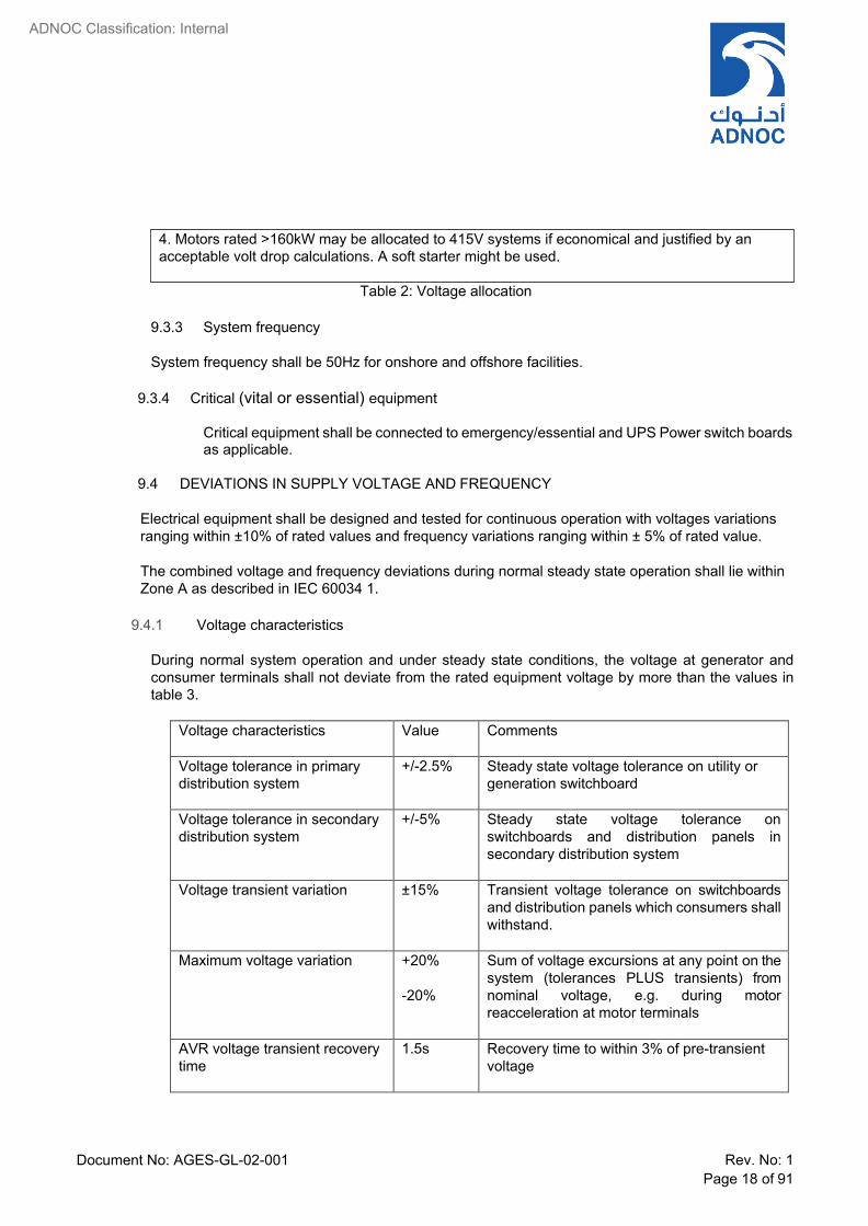
Table 2: Voltage allocation
9.3.3 System frequency
System frequency shall be 50Hz for onshore and offshore facilities.
9.3.4 Critical (vital or essential) equipment
Critical equipment shall be connected to emergency/essential and UPS Power switch boards as applicable.
9.4 DEVIATIONS IN SUPPLY VOLTAGE AND FREQUENCY
Electrical equipment shall be designed and tested for continuous operation with voltages variations ranging within ±10% of rated values and frequency variations ranging within ± 5% of rated value.
The combined voltage and frequency deviations during normal steady state operation shall lie within Zone A as described in IEC 60034 1.
9.4.1 Voltage characteristics
During normal system operation and under steady state conditions, the voltage at generator and consumer terminals shall not deviate from the rated equipment voltage by more than the values in table 3.
Voltage characteristics Value Comments
Voltage tolerance in primary distribution system
+/-2.5% Steady state voltage tolerance on utility or generation switchboard
Voltage tolerance in secondary distribution system
+/-5% Steady state voltage tolerance on switchboards and distribution panels in secondary distribution system
Voltage transient variation ±15% Transient voltage tolerance on switchboards and distribution panels which consumers shall withstand.
Maximum voltage variation +20% -20%
Sum of voltage excursions at any point on the system (tolerances PLUS transients) from nominal voltage, e.g. during motor reacceleration at motor terminals
AVR voltage transient recovery time
1.5s Recovery time to within 3% of pre-transient voltage
4. Motors rated >160kW may be allocated to 415V systems if economical and justified by an acceptable volt drop calculations. A soft starter might be used.
Document No: AGES-GL-02-001 Rev. No: 1 Page 19 of 91
ADNOC Classification: Internal
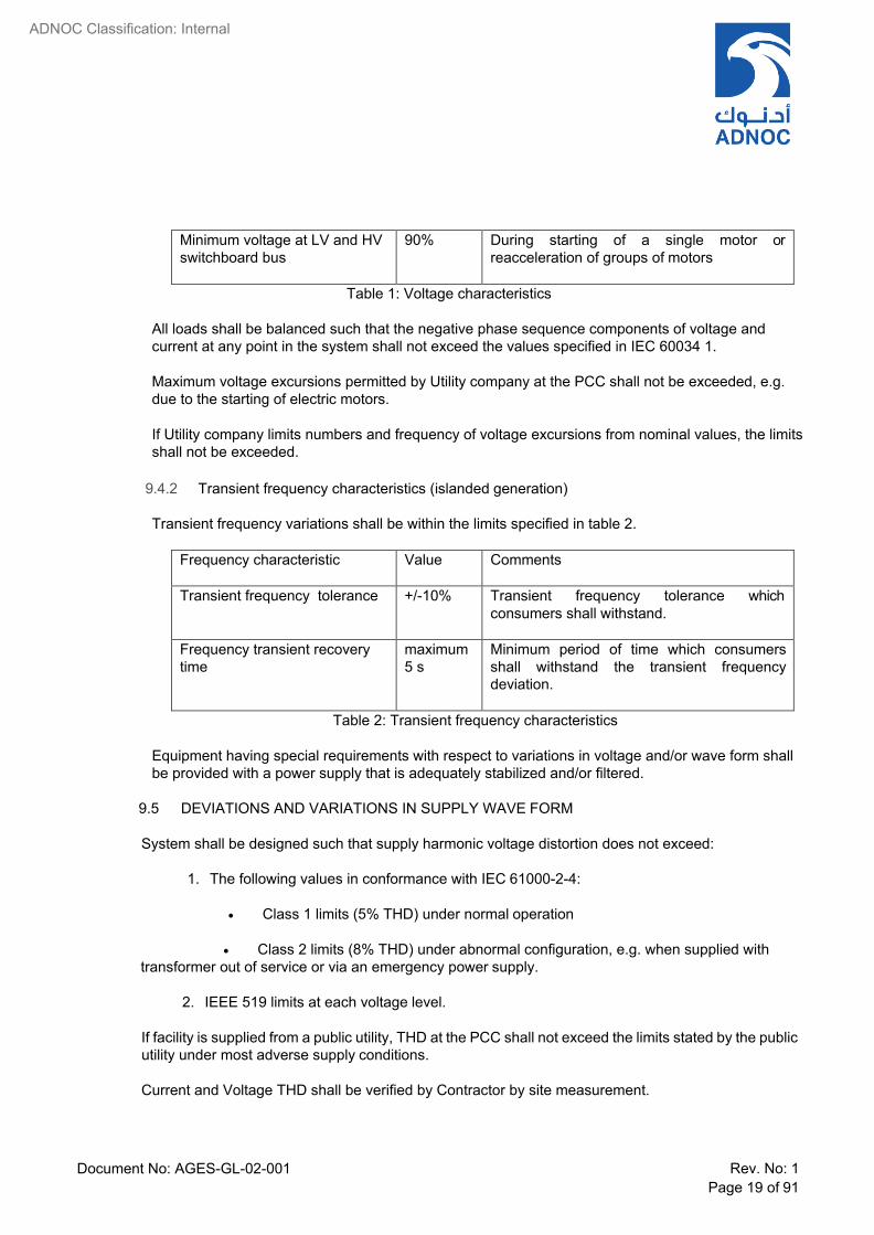
Minimum voltage at LV and HV switchboard bus
90% During starting of a single motor or reacceleration of groups of motors
Table 1: Voltage characteristics
All loads shall be balanced such that the negative phase sequence components of voltage and current at any point in the system shall not exceed the values specified in IEC 60034 1.
Maximum voltage excursions permitted by Utility company at the PCC shall not be exceeded, e.g. due to the starting of electric motors.
If Utility company limits numbers and frequency of voltage excursions from nominal values, the limits shall not be exceeded.
9.4.2 Transient frequency characteristics (islanded generation)
Transient frequency variations shall be within the limits specified in table 2.
Frequency characteristic Value Comments
Transient frequency tolerance +/-10% Transient frequency tolerance which consumers shall withstand.
Frequency transient recovery time
maximum 5 s
Minimum period of time which consumers shall withstand the transient frequency deviation.
Table 2: Transient frequency characteristics
Equipment having special requirements with respect to variations in voltage and/or wave form shall be provided with a power supply that is adequately stabilized and/or filtered.
9.5 DEVIATIONS AND VARIATIONS IN SUPPLY WAVE FORM
System shall be designed such that supply harmonic voltage distortion does not exceed:
1. The following values in conformance with IEC 61000-2-4:
• Class 1 limits (5% THD) under normal operation
• Class 2 limits (8% THD) under abnormal configuration, e.g. when supplied with
transformer out of service or via an emergency power supply.
2. IEEE 519 limits at each voltage level.
If facility is supplied from a public utility, THD at the PCC shall not exceed the limits stated by the public utility under most adverse supply conditions.
Current and Voltage THD shall be verified by Contractor by site measurement.

Document No: AGES-GL-02-001 Rev. No: 1 Page 20 of 91
ADNOC Classification: Internal
Unless a higher value is stated on the data sheets all equipment shall be suitable for operation on a network supply with harmonic voltage THD up to 8%.
Equipment which will produce a sustained DC component in the AC. supply system shall not be utilized.
Notes:
The values of maximum permissible harmonic distortion are to be regarded as a guide to good practice aimed at minimizing the risk of damage to or malfunction of system electrical equipment and at preventing system over voltages and over currents due to resonant effects. However, the latter possibility is dependent on the system capacitance (including that employed for power factor correction), the source and load impedances and the harmonic current requirements of the nonlinear load, etc. The necessity of protective measures is consequently a matter to be ascertained for each Project individually, depending on the relative magnitude of the above mentioned parameters. The above mentioned harmonic voltage distortion limits do not apply to the input terminals of individual items of harmonic generating equipment, e.g. converters, which are supplied via transformers or series reactors.
9.6 SYSTEM POWER FACTOR
The overall system power factor, inclusive of reactive power losses in transformers and other distribution system equipment, shall not be less than 0.90 lagging at rated design throughput of the Plant. The power factor shall be determined at:
• The terminals of the generator(s), when power is supplied from in plant generation. • The PCC (Point of Common Coupling with an external network), when power is supplied from
a public utility. The plant power system shall be designed such that the power factor stated by the public utility is achieved with a design margin of at least 2%.
Note: As measured, the power factor will be an average value determined over the metering integration period, typically 30 minutes.
Any improvement of power factor beyond that necessary to achieve the foregoing aims shall be considered on an economic basis, e.g. reduction in distribution system equipment ratings, reduction in kVAr charges.
Where necessary, power factor correction shall be effective by one or more of the following methods, which are stated in order of preference. The method selected depends on reliability and economic considerations.
• Variation of the Excitation of synchronous generators. • Variation of the Excitation of synchronous motors. • Suitably rated static capacitor banks connected to distribution switchboards or group motor
control centres via suitably protected switching devices.
9.7 SYSTEM EARTHING
132kV System : Solidly earthed

Document No: AGES-GL-02-001 Rev. No: 1 Page 21 of 91
ADNOC Classification: Internal
33 kV system : Resistance earthed, unless otherwise stated in the Requisition.
11 kV System : Resistance earthed
3.3 kV System : Resistance earthed
415V System : Solidly earthed
240V UPS : Solidly earthed
110V DC : Unearthed
24V DC : Unearthed.
9.8 LOAD ASSESSMENT AND ELECTRICITY CONSUMPTION
A schedule of the installed electrical loads, the maximum normal running plant load and the peak load, expressed in kilowatts and kilovars and based on the plant design capacity when operating under the site conditions specified, shall be prepared. This shall be completed and updated regularly throughout the design stage of the Project and shall form the basis for provision of the necessary electricity supply and distribution system capacity.
Formula for determining the total electrical loads shall be as follows:
• Maximum normal running plant load = x (%) E + y (%) F • Peak load = x (%) E + y (%) F + z (%) G.
where:
E = sum of all continuously operating loads.
F = sum of all intermittent loads.
G = sum of all stand by loads.
x, y and z are diversity factors.
Values shall be determined by the CONTRACTOR for the diversity factors appropriate to the type of Plant. The values of the diversity factors x, y and z must take account of the individual drives or consumers which make up the continuous, intermittent and stand by loads, respectively. For example, y (%) F cannot be less than the largest individual intermittent drive or consume. In such case 100% of largest individual intermittent and/or stand-by load shall be considered for sizing the supply switchboard and its incoming transformer.
Subject to the above considerations, the following default values could be used for initial load assessments, or if the diversity factors have not been finalized:

Document No: AGES-GL-02-001 Rev. No: 1 Page 22 of 91
ADNOC Classification: Internal
x = 100% (By definition, at rated plant throughput all driven equipment should be operating at its duty point. However, some diversity may need to be applied to non- process loads, e.g. offices and workshop power and lighting (typically 90%).
y = 30%
z = 10%
A separate schedule shall be prepared for each switchboard, the total of all switchboard loads being summarized as required to arrive at the maximum normal running and peak loads for each substation and for the Plant overall.
Loads shall be allocated to switchgear busses to balance loading across the plant and allow continuity of process operation under maintenance or abnormal conditions.
Duty and standby loads shall be allocated to different buses.
Account should be taken of large intermittent or stand by loads for these summations, as described above. All loads to be shed during an under frequency condition shall be identified as such in the "remarks" column. All loads to be automatically restarted after a voltage dip shall be identified as such in the restarting column. The percentage of total intermittently operating load that contributes to the maximum normal running load will depend on Plant operations.
Depending on steam/electricity supply availability, the use of non-electrical drivers for stand by duties and the total number of units installed, only a small number of the largest electrical standby units may have to be considered when establishing the peak load.
Where a group of drives operate as a unit, it shall be considered as an individual consumer. Attached table format given in Appendix 7 shall be used for this purpose.
9.9 DISTRIBUTION PHILOSOPHY
9.9.1 Power supply distribution within the plant shall be as indicated in single line diagrams or Project
Definition Report.
9.9.2 11 kV and above bus bars systems should be continuous with bus section breakers in normally closed position.
9.9.3 11kV bus section breaker may by in normally open condition with ATS (Auto Transfer System)
if the design necessitate subject to COMPANY approval.
9.9.4 Feeders to continuous process unit substations shall be radial type. Each unit substation shall have two 100% feeders terminating directly on transformers.
9.9.5 Adequately rated emergency diesel generators shall be provided in the plant at strategic
locations to feed vital loads. Emergency Generator shall start and come on line automatically in the event of Mains failure. Periodic testing for diesel generator on load synchronizing and

Document No: AGES-GL-02-001 Rev. No: 1 Page 23 of 91
ADNOC Classification: Internal
paralleling facilities with the Mains shall be provided. Loads to be fed from emergency supply shall include, but not be limited, to the following:
• AC input to one unit of all AC & DC UPS Systems. • Twenty percent (20%) Plant lighting including substations/control rooms. • Essential auxiliaries of major machinery. • In case of any particular emergency load is in (3 x 50%) configuration, i.e. (2W+1S), then 2
units shall be fed from the emergency bus which is fed from bus B in normal operation. Whereas, one unit shall be fed from bus A.
• All lights in main control room. • Fire Water Jockey Pumps • Auxiliaries of main power generator(s) • Critical pumps of hydrocarbon drainage sump pump. • Any other critical load required by process to have emergency backup supply.
9.9.6 The need for a load shedding scheme shall be studied and if required a microprocessor/PLC
based load shedding scheme shall be provided. As a backup to this, under frequency load shedding in conjunction with rate of change of frequency relays shall also be provided.
9.9.7 Automatic reacceleration/re start scheme shall be provided for those motors dictated by process
requirements. (See Appendix 7).
9.10 SYSTEM PROTECTION AND METERING
9.10.1 Protection and metering scheme for the electrical distribution network shall be as shown on single line diagrams.
9.10.2 Unit type protection with overlapping zones shall be provided as primary protection for the
various elements of the power system.
9.10.3 Graded time over current protection shall be provided as backup protection. All protective relays shall be microprocessor based (unless specific protection is not available with Microprocessor Technology), programmable type and shall be of the same make throughout the Plant.
9.10.4 Test blocks shall be provided on all switchgears to facilitate testing of relays and meters.
9.10.5 Ring type CT shall be installed for zero sequence protection for better sensitivity and to improve
the accuracy of the protection.
9.10.6 For purpose of standardization / stock level optimization in order to limit operation, maintenance and replacement costs, the protection relays shall be digital, multifunction, programmable, with serial IEC 61508 communication.
9.10.7 Power Generation and Distribution Facilities
Protection and metering to be provided for different equipment/circuits shall generally be as shown on single line diagrams and shall include but not be limited to the following:

Document No: AGES-GL-02-001 Rev. No: 1 Page 24 of 91
ADNOC Classification: Internal
(a) Main Generators:
• Overvoltage protection • Differential protection. • Voltage restrained over current protection/impedance relay • Earth fault protection. • Reverse power protection. • Loss of excitation protection. • Negative Sequence protection. • Rotor earth fault protection. • Diode failure protection. • Under frequency/overfrequency protection. • Stator winding over temperature protection connected to winding RTDS. • Generator lockout relay. • Mechanical protection devices such as high vibration, high bearing temperature, etc. • Voltmeter with selector switch. • Ammeter with selector switch. • Frequency meter. • kW meter. • KVAR meter. • kWh meter. • Power factor meter. • Field volt meter. • Field ammeter. • Hours run counter. • kW transducer. • Synchroscope • Over fluxing • Generator star point.
Note: Redundant protection relay to be provided for main generator primary protection.
(b) Emergency Diesel Generators:
• Voltage Restrained Over Current Protection. • Earth Fault Protection. • Negative Phase Sequence Protection • Stator winding over temperature protection connected to winding RTD's, • Rotor E/F Protection. • Over Voltage Protection • Reverse Power. • Field Failure protection (loss of excitation protection). • Diode Failure Protection. • Lockout Relay. • Voltmeter with Selector Switch. • Ammeter with Selector Switch. • KW / KVAR/ kWH Meters. • P.F. Meter. • Frequency meter.

Document No: AGES-GL-02-001 Rev. No: 1 Page 25 of 91
ADNOC Classification: Internal
• Field Ammeter & Volt Meters. • Hours Run Counter. • Synchroscope
(c) 11 kV Motor Feeder:
• Multimodule Motor Protection relay comprising:
− Overload protection. − Negative sequence protection. − Short circuit protection. − Locked rotor protection. (Prolonged start) − Motor stall / Jam protection (Mechanical Jam at running condition) − Earth fault protection with CBCT. − Field failure (for synch. motors) − Out of step for synchronous motors. − Anti-single phase protection shall be required for fused contactor type motor feeders.
• Undervoltage protection. • Adjustable Time Delay Re start Inhibit Protection. • Differential protection. • Thermal relay connected to winding and bearing RTDS. • Ammeter with selector switch. • Hours run counter
(d) Feeder for 132/34.5 kV, 33/11.5 kV, 11/3.45 kV or 11/0.433 kV or 3.3/0.433 kV Transformers:
• Inverse Definite Minimum Time (IDMT) relay (51) with high set instantaneous unit (50) in all
three phases. • Instantaneous earth fault relay (50N) (This shall be a high impedance relay to avoid tripping
while charging transformers). • Differential relay for transformers rated 10 MVA and above (87). The transformer differential
protection shall be low impedance relay and shall be able to avoid nuisance tripping while charging the transformer.
• Line differential protection (87L) for feeders ≥ 500 meters • Transformer lock out relay (86). • Ammeter with selector switch. • kWh meter.
(e) Incoming from 220/34.5 kV, 132 kV/34.5 kV, 33/11.5 kV, 11/3.45 kV, 11/0.433 kV, 3.3/0.433
kV Transformers:
• Bus bar zone protection with back-up for switchboards above 33kV. Bus zone protection shall be provided for 33kV & 11kV SWBDs, in special circumstances such as:
− If a Busbar fault cannot be cleared within 1 s. − Switchgears supplied from multiple sources with generators. − Plant main intake switchgears. − System design requirements (e.g. critical fault clearing time for system stability).
• IDMT over current and Earth fault relays (51, 51N).

Document No: AGES-GL-02-001 Rev. No: 1 Page 26 of 91
ADNOC Classification: Internal
• Separate IDMT over current and Earth fault relays (51, 51N) mounted on Bus coupler & riser aux. compartments facial shall be provided for bus coupler protection. Partial differential scheme shall be provided for 3.3KV and 415 Volt switchboards or in switchboards where bus differential protection is not provided and SWG will have normally open tie arrangement. Partial differential relay shall be coordinated with downstream load feeders.
• Directional overcurrent and earth fault relays (67.67 N) only for 132 kV/34.5 kV transformers and 33 kV/11.5 kV transformers.
• Lockout relay (86) for use with the above relays. • Auxiliary flag operated relays for transformer Buchholz (or sudden pressure), oil temperature,
winding temperature, oil level, etc. Sudden Pressure Relay (SPR) shall be provided for OLTC where applicable.
• Restricted earth fault protection for LV winding of transformers (64). • Separate relay for Standby earth fault protection (51G) connected to transformer neutral CT
and lockout relay 86. • Differential relay for incoming Transformers above 10MVA fed from the Grid (ADNOC
Onshore / TRANSCO). Transformer differential protection shall cover both the primary and secondary side cables/bus ducts if separate line differential protection is not provided.
• Lockout Relay for transformer (86T) for connection to 26, 49, 63, 64, 71. • Line differential protection (87L) for 400kV, 220kV and 132 kV cables (Receiving end) • Ammeter with selector switch. • Voltmeters with selector switch connected to PT on incoming side.
(f) 11 kV Feeder to a Secondary Substation (SENDING END):
• Line differential protection (87L). • IDMT over current and earth fault protection (51, 51 N). • Lockout relay (86). • Ammeter with selector switch. • kWh meter.
(g) 11 kV Feeder to a Secondary Sub Station (RECEIVING END):
• Line differential protection (87L). • IDMT overcurrent and earth fault protection (51, 51N) connected in a partial differential
scheme with 11 kV bus section breaker CTs. Switchgear should be provided with open tie arrangement.
• Directional over current relay (67, 67N) • Lock out relay (86). • Ammeter with Selector Switch. • Voltmeter with Selector Switch connected to PT on incoming side
(h) 3.3 kV Motor Feeder
• Multimodule motor protection relay comprising:
− Overload Protection. − Negative Sequence Protection. − Locked rotor protection. − Earth Fault Protection with CBCT. − Adjustable Time Delay Restart Inhibit Protection.

Document No: AGES-GL-02-001 Rev. No: 1 Page 27 of 91
ADNOC Classification: Internal
• HRC fuses for short circuit protection. • Undervoltage protection. • Lockout Relay (86). • Thermal relay connected to windings and bearing RTD's if required (non quadratic, load
torques for winding RTD's and sleeve bearings for bearing RTD's) • Ammeter with selector switch. • Hours Run Counter
(i) 33 kV or 11 kV Current Limiting Reactor or Is limiter
• Differential protection of line (87L) or pilot wire relay (85) as shown in single line diagrams. • IDMT overcurrent and earth fault current (51, 51 N) on both circuit breakers. • Lockout relay (86) on both circuit breakers • Synchro-check relay on both circuit breakers. • If power flows in either direction, it is essential that in case of fault, the current limiting reactor
is completely isolated (both circuit breakers have to be inter-tripped and interlocked by the lockout relay (86) of the other one).
• Ammeter with selector switch on each circuit breaker. • Wattmeter (with zero center deflection with "N" and "OUT" marking) on each circuit breaker. • Undervoltage (alarm).
(j) 415V Motor Protection
All the motors shall be fed through Contactors and MCCB. The MCCB shall have short circuit capacity similar to the bus bar. The starter shall be equipped with the multifunction protections relay comprising as a minimum the following:
• Short circuit protection • Overload Protection • Earth fault protection for all motors. CBCT shall be used for 30kW motors and above. • Single phasing protection • Restart facility • Ammeter with proper scale (can be integrated in Digital relay flush mounted screen) • CT’s for remote ammeter.
(k) 415V Power Feeder
All the power feeders shall be fed through MCCB or (MCCB +Contactor) having short circuit capacity similar to the bus bar, equipped with inherent protection comprising as a minimum the following:
• Short circuit protection • Overload protection. • Earth fault protection for 63A feeders and above using CBCT. • Shunt trip coil if specified. • Ammeter with selector switch (3 positions + 0) for feeders rated 63A and above.
9.11 ELECTRICAL POWER SYSTEM MANAGEMENT
9.11.1 INTEGRATED PROTECTION AND CONTROL SYSTEMS (IPCS)

Document No: AGES-GL-02-001 Rev. No: 1 Page 28 of 91
ADNOC Classification: Internal
A centralized monitoring and supervision of the Electrical System shall be implemented through a dedicated Integrated Protection and Control System" (IPCS) which will interface with the plant process Distribution and Control System (DCS).
IPCS shall incorporate data logging, fault recording, plant performance trends, energy management, recording plant performance trends and recording of transient disturbances in the power system trip signals from the electrical protection shall be derived locally from MCC and Switchgear and not from part of external control monitoring system.
The IPCS shall be integrated with the DCS system so that the complete electrical system status of all the plant substations are made available on the IPCS / DCS.
Electrical power management system design shall have capabilities to support various network topologies such Star, Mesh, Bus etc. In addition the system shall support interfaces to DCS such as OPC, Modbus over Ethernet, Modbus Serial communication etc.
Basic requirements for IPCS are described in specification DGS 1630 004.
9.11.2 LOAD MANAGEMENT LOAD SHEDDING & TRANSIENT DISTURBANCE MONITORING
(LMLS & TDM)
In areas where power generation is required to be provided, CONTRACTOR to provide a LMLS & TDM System in accordance with Specification No DGS-1630-036.
LMLS system shall use high speed IEC 61850 communication capability with a redundant fibre communication loop.
9.11.3 OT SECURITY REQUIREMENTS
Electrical Power System Management, IPCS...etc. shall comply with company OT Security requirements. OT security requirements shall include firewall solutions, Centralized Antivirus, Centralized Patch management solutions, Active directory, Network monitoring solutions, Whitelisting, Security Information and Events Management solutions, System Hardening, etc. For details, refer Company OT Security policy (TE-POL-001), OT Security procedure (OT-PR- 016) and OT security guidelines (TE-GU-028)
9.12 POWER MONITORING UNIT
Substations containing 11 kV, and above, switchgear shall have a Power Monitoring Unit (PMU) installed on each segment of switchgear bus. PMU shall be capable of detecting and recording voltage and current sags and surges, monitor required metering parameters, capture current and voltage waveforms, and determine sequence of events (breaker tripping, lockout relaying) to 1 ms accuracy. The unit shall be capable of using 110 Vdc control power to ensure operation during power outages.
PMU shall be a high speed source of electrical distribution information interfacing with IPCS to permit user to execute informed decisions on system events, power sags and surges, efficiency, maintenance scheduling and troubleshooting

Document No: AGES-GL-02-001 Rev. No: 1 Page 29 of 91
ADNOC Classification: Internal
10 CLASSIFICATION OF HAZARDOUS AREA
10.1 Hazardous area shall be classified into zones in accordance with IEC 60079 10 as follows:
Zone "0" In which an explosive gas air mixture is continuously present or present for long periods.
Zone “1" In which explosive gas air mixture is likely to occur in normal operation. Zone "2" In which an explosive gas air mixture is not likely to occur, and if it occurs it will
only exist for short time. 10.2 The area classification shall be based on latest edition of EI 15 Energy Institute Model Code of
Safe Practice Part 15: The Area Classification Code for Installations Handling Flammable Fluids).
10.3 In determining the area classification, the contents of each item of equipment within the plant shall be considered from the point of view of being a potential source of hazard.
Schedule shall be produced indicating the following data with respect to contents of each item of equipment:
• Type of Material. • Chemical Composition. • Flash Point. • Maximum design operating temperature and Pressure: • Flammable Range (% by Volume in Air). • Gas or Vapor Density. • Self-Ignition Temperature. • Temperature Class. • Gas Group. • Source and Grade of Release. • Extent of Area made Hazardous under:
− Normal Ventilation. − Ventilation failure.
10.4 Special consideration shall be given to those areas where large volume of hazardous materials
are being handled or high pressures are utilized.
10.5 Considerations shall be given to classification of areas around sampling points, relief vents etc. Location of electrical equipment near sampling points, relief vents shall be avoided.
10.6 Within the battery limits of the Process areas all electrical equipment, not installed in non-
hazardous areas in buildings, shall be certified for use in hazardous areas. This is irrespective of whether the actual equipment location is classified as non-hazardous Inside the battery limits of process areas the ENGINEER/EPC Contractor shall prepare the hazard area classification drawings by considering IP code Part 15 section 2.7 last paragraph and introduce a new legend for extended hazard area (different from legend for zones 0, 1, 2) to cover the small non- hazardous pockets which are located within the boundaries of a process area.
10.7 Grouping of various hazardous gases and vapors shall be as per IEC 60079.

Document No: AGES-GL-02-001 Rev. No: 1 Page 30 of 91
ADNOC Classification: Internal
10.8 Electrical equipment selection and installation for the classified area shall be in accordance with IEC 60079 and BS 5345 with the exception that 11 kV high voltage motors for installation in Zone 2 areas shall be EEx(d)/EEx(p) type.
10.9 Equipment selection shall follow the table 3.
Type of Zone
Description of Electrical Apparatus
Zone 1 Zone 2 Electrical apparatus for Zone 1 are suitable for Zone 2.
Low voltage induction motors Flameproof "d" + increased safety terminal box “e": EEx”de”.
Non-sparking induction motors "n". (IEC 60079-15)
Note:
Motors supplied at varying frequency and voltage by a convertor shall be tested with the specified convertor or with a comparable convertor in reference to the output voltage and current specifications, in accordance with IEC 60079-15 Requirements
HV Induction motors (6.6kV or 3.3 KV)
Flameproof "d" + increased safety terminal box “e": EEx”de”.
EEx”de” if the motor drives a centrifugal /screw hydrocarbon gas compressor.
else Non sparking induction motors "n"
HV Induction motors (11 kV) Flameproof "d" +increased safety terminal box “e": EEx"de”. Or, EEx”p”
Same as Zone-1.
HV Synchronous motors Ex “pxb” Terminal box may be Ex”eb”
Ex “pzc” or EX “pxb” and Ex “ec”
Arcing and sparking equipment
(switches, circuit breakers,
switchgear, panel boards,
Flameproof "d" + increased safety enclosure "e" : EEx"de")
Same as in Zone 1

Document No: AGES-GL-02-001 Rev. No: 1 Page 31 of 91
ADNOC Classification: Internal
control stations, etc…)
Plugs and sockets Flameproof "d"+ increased safety enclosure "e": (EEx"de")
Same as in Zone 1
Lighting fixtures Flameproof "d" increased safety "e" : (EEx"de")
Intrinsic safety "I" : (EEx “” for portable torch lamps
Flameproof (EEx"d")
Same as in Zone 1
Heating apparatus, (heat
tracing, heating resistance
etc)
Increased safety "e" : (EEx"e")
Flameproof "d : (EEx"d").
Same as in Zone 1
No sparking equipment (like
junction boxes, etc.
Increased safety "e" : (EEx"e")
Flameproof "d": (EEx"d").
Same as in Zone 1
Table 3: Selection Of Electrical Equipment For Gas Hazardous Area
All equipments installed in classified hazardous area shall comply with the ATEX Directive. Equipment certification shall be acceptable if equipment is tested, approved and certified by independent Notified Bodies/Certification Bodies recognized under the EU ATEX and IECex certification schemes.
10.10 COMBUSTIBLE DUST
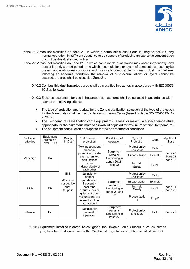
10.10.1 Combustible dust hazardous area shall be classified into zones in accordance with IEC 60079 10-2 as follows:
Zone 20 An area in which combustible dust, as a cloud, is present continuously or frequently, during normal operation, in sufficient quantity to be capable of producing an explosive concentration of combustible dust mixed with air, and/or where layers of dust of uncontrollable and excessive thickness can be formed.
Document No: AGES-GL-02-001 Rev. No: 1 Page 32 of 91
ADNOC Classification: Internal
Zone 21 Areas not classified as zone 20, in which a combustible dust cloud is likely to occur during normal operation, in sufficient quantities to be capable of producing an explosive concentration of combustible dust mixed with air.
Zone 22 Areas, not classified as Zone 21, in which combustible dust clouds may occur infrequently, and persist for only a short period, or in which accumulations or layers of combustible dust may be present under abnormal conditions and give rise to combustible mixtures of dust in air. Where, following an abnormal condition, the removal of dust accumulations or layers cannot be assured, the area shall be classified Zone 21.
10.10.2 Combustible dust hazardous area shall be classified into zones in accordance with IEC 60079
10-2 as follows:
10.10.3 Electrical equipment for use in hazardous atmospheres shall be selected in accordance with each of the following criteria:
• The type of protection appropriate for the Zone classification selection of the type of protection
for the Zone of risk shall be in accordance with below Table (based on table D2-IEC60079-10- 2, 2009).
• The Temperature Classification of the equipment (T Class) or maximum surface temperature appropriate for the hazardous materials involved adjusted for maximum ambient temperature.
• The equipment construction appropriate for the environmental conditions.
Protection afforded
Equipment protection level (EPL)
Group (III= Dust)
Performance of protection
Conditions of operation
Type of Protection
Code Applicable
Zone
Very high
Da
III B
(B = Non conductive
dust) Sulphur
Two independent means of
protection or safe even when two malfunctions
occur independently of
each other
Equipment
remains functioning in zones 20, 21
and 22
Protection by Enclosure Ex ta
Zone 20 Zone 21 Zone 22
Encapsulation Ex maD
Intrinsic Safety
Ex iaD
High
Db
Suitable for normal
operation and frequently occurring
disturbances or equipment where malfunctions are normally taken into account
Equipment remains
functioning in zones 21 and
22
Protection by Enclosure Ex tb
Zone 21 Zone 22
Encapsulation Ex mbD Intrinsic Safety Ex ibD
Pressurizatio
n
Ex pD
Enhanced
Dc
Suitable for normal
operation
Equipment remains
functioning in zone 22
Protection by
Enclosure
Ex tc
Zone 22
10.10.4 Equipment installed in areas below grade that involve liquid Sulphur such as sumps,
pits, trenches and areas within the Sulphur storage tanks shall be classified for IEC

Document No: AGES-GL-02-001 Rev. No: 1 Page 33 of 91
ADNOC Classification: Internal
Zone 1, Group IIB for H2S gas with a maximum rated surface temperature of 185°C at 54 °C ambient.
10.10.5 For Electrical equipment in zone 21/22, the following shall apply:
• Indoor/Outdoor (under shed) Zone 21/Zone22:
Ex tb IIIB, T 146°C, Tamb 54°C, IP65 • Outdoor direct sun exposed Zone 21/Zone22:
Ex tb IIIB, T 115°C, Tamb 54°C, IP65.
10.11 EX EQUIPMENT REGISTER FOR CEE EQUIPMENT
In compliance with Standard IEC 60079-17 to inspect and maintain CEE Equipment (Certified Electrical Equipment), the EPC Contractor shall develop and provide an Ex Equipment Register for all the CEE Equipment installed in the plant. The Ex equipment register shall be developed in suitable format for import into the computerized maintenance management system, with minimum requirements as stated in APPENDIX 4 of this design guide.
11 SYSTEM STUDIES
11.1 System Studies for the Electrical Power Distribution System shall be carried out and shall include
but not be limited to the following:
• Load Flow Studies. • Short Circuit Studies (3 phase and earth fault). • Motor Starting and Run Up • Transient Stability • Voltage profile on different bus bars during motor starting and fault conditions. • Frequency response on loss of generation and load shedding. • Harmonic Distortion Studies. • Short circuit studies shall be carried out in accordance with IEC 60909.
For systems with "near to source" power generation IEC 61363 may be used to determine adequacy of equipment to clear short circuit fault.
• Protection studies • Arc flash assessments
11.2 Arc flash assessments
11.2.1 Arc flash analysis calculations shall be conducted to determine arc flash incident levels at:
• Switchgear buses. • MCC buses. • Bus section breakers. • Overcurrent and isolation device locations of overhead lines and open-air substations. • Power panels rated 240 V and higher.
11.2.2 Calculations shall be performed in accordance with one of the following methods:
(i) IEEE 1584.
Document No: AGES-GL-02-001 Rev. No: 1 Page 34 of 91
ADNOC Classification: Internal
(ii) IEEE 1584 simplified LV method
(iii)Lee method
(iv) German accident insurance organisation
11.2.3 Results of arc flash studies shall be used to:
• Optimise power system design to minimise arc flash incident energy. • Risk assess activities and determine PPE requirements for operation and maintenance tasks.
11.2.4 PPE requirements shall be based on the highest arc incident energy at the busbar location.
11.2.5 Designs shall evaluate methods to remove risk from arcing incidents, eliminating the need to
operate live equipment to as low as reasonably practicable, e.g. by:
• Isolation of equipment • Eliminating the need for manual racking in or switching of breakers on live equipment from in
front of the equipment. • Use of early detection protection such as arc UV detection combined with pressure detection • Use of maintenance mode protection relay settings whilst working in close proximity to
switchgear. • Venting arc incident gas exhaust to an outdoor area via ducting
11.2.6 Arc incident energy levels should be reduced to less than 8 cal/cm2.
11.2.7 Incident energy levels that cannot be reduced to less than 8 cal/cm2 and below 40 cal/cm2 shall
be permitted if approved by Company responsible engineer.
11.2.8 Credible design configurations that result in an incident energy levels 40 cal/cm2 shall not be permitted.
11.3 SAFOP study (Safety and Operability review of Electrical Systems).
The scope shall comprise the following:
• Project Description (All relevant key documents). • Study Scope Identification in terms of:
− Voltage levels. − No. of Substations. − No. of systems (Control, protection, black starting, etc.)
• Study execution req. (SYSOP, PHILOP, SAFAN and OPTAN). • Carry out workshop with concerned parties. • List of Deliverables (reports, etc.) • The complete Electrical SAFOP study has four modules SAFAN, PHLOP, SYSOP, and OPTAN. • During FEED phase the SYSOP, PHILOP and SAFAN studies will be required. • SYSOP study module will focus on assuring design security, design fit with Business requirements,
and Design Quality (best practice).

Document No: AGES-GL-02-001 Rev. No: 1 Page 35 of 91
ADNOC Classification: Internal
• PHILOP study module will focus on assuring the critical philosophies that underpin the electrical facility (BOD, electrical safety, electrical operating and work practice, protection, load shed, black start, etc.) fit with business requirements.
• SAFAN study module will focus on assuring safety of Personnel (COMPANY and non-COMPANY) and include a critical review of construction and commissioning risks and environment, permits, barriers etc.). SAFAN shall be started in FEED and shall be continue to be completed in EPC.
12 SUBSTATIONS
12.1 Substations shall be located in safe areas, as close as feasible to load centres.
A minimum distance of 30m from any source of hazard shall be considered for locating substations.
12.2 Substation shall be designed to resist the Blast Loading (peak side-on overpressure) as per the QRA report and DGS-1882-001 (Structural Design Basis).
12.3 Onshore substations shall be elevated such that the height from grade to the underside of ceiling
or beams, whichever is at the lower level shall be a minimum of 1800 mm.
12.4 Wire mesh fence access protection with lockable door (s) shall be provided for cable cellars and outdoor transformer pens.
12.5 Substations shall be provided with lightning protection in accordance with IEC 62305.
12.6 Substations shall be provided with two 100% rated air conditioning units to maintain an internal
temperature of 25'C. Relative humidity shall be 50% ± 10%.
Positive pressure shall be maintained within the substation.
The HVAC equipment shall be installed in a separate room with separate access door, outside the switchgear room.
12.7 Personnel access doors with air lock and equipment access doors (2.5m x 3m high) of adequate
size shall be provided for all substations.
There shall also be an emergency escape door.
All doors in the substation shall be fitted with panic bar.
12.8 Following minimum working clearances shall be followed/provided:
• In front of HV switchgear : 2500 mm
• In front of LV switchgear : 1500 mm
• Between HV & LV switchgear : 2500 mm
• Between two rows of LV switchgear : 1500 mm

Document No: AGES-GL-02-001 Rev. No: 1 Page 36 of 91
ADNOC Classification: Internal
• Rear side of HV & LV switchgear (requiring rear cable access)
: 1000 mm
• Rear side of HV & LV switchgear (for front access and front connection only)
Panels for which back access is not required (if installed close to wall)
: 100 mm
• Between equipment ends and equipment ends and wall (after keeping a provision for Extension)
: 1000 mm
• Around transformers : 1000 mm
• Between transformer and building wall : 750mm
• From highest point of equipment to underside of lowest roof beam
: 500 mm
• Between back of UPS and wall : 1000 mm
• Around battery banks : 1000 mm
12.9 Entire substation floor except the area where switchgears are to be installed shall be covered with 6 mm thick rubber flooring norament type 926S or approved equivalent.
Floor steel shall be installed, level and flush with finished rubber flooring for mounting the switchgear. Switchgear shall be bolted to the floor steel.
12.10 Cables should enter the substation from below.
12.11 All cable entry holes shall be sealed after cable installation.
12.12 Suitable cable support frames made of 102 x 51 mm channel as main member and P1000
unistrut as cross members shall be provided below the substation to support cables (distance between supports not to Exceed 600 mm).
12.13 All high voltage cables shall be clamped to the unistrut by suitable cable clamps of BICC make
or approved equivalent. All LV and control cables shall be fixed by EVA coated stainless steel all-purpose band "Band it" or approved equivalent.
12.14 Cables to wall mounted panels/devices in substation shall be routed in suitable plastic trunking
the colour of which shall match the wall painting.
Alternatively, heavy duty galvanized steel trunking for indoor lighting and rigid galvanized steel conduits for outdoor lighting, indoor and outdoor socket outlets may be used with single core wires.
The galvanized trunking/conduits shall be epoxy painted to match the color of the wall painting.

Document No: AGES-GL-02-001 Rev. No: 1 Page 37 of 91
ADNOC Classification: Internal
12.15 For cable glanding below the substation, suitable IP55 gland box below switchgear/MCC fixed on bottom side of substation floor shall be provided.
12.16 The gland box shall be fabricated out of 50 x 50 x 8 mm M.S. angle and 2 mm thick side sheets
and 6 mm thick gland plate at the bottom. The box shall have removable covers of 2 mm thick galvanized sheet on front and rear complete with neoprene gaskets. The plates on other two sides and the gland plate (after drilling required number of holes) shall be welded to the angle frame. The box shall be hot dip galvanized after fabrication.
12.17 Each Substation shall be provided with the following:
• One Desk • Two Chairs • Electrical Key single line diagram and area classification drawings framed and displayed on
the wall. • One cupboard for keeping drawings, documents, safety, tools etc. • One Quartz clock, wall mounted • First Aid Box • Telephone • Six (06) feet fiberglass stepladder with a working platform. • Electrical safety tools (live line detector, rubber hand glove, earthing discharge tool). • Overall key single line Diagram of the main Power Distribution System (to be framed & wall
mounted). • Shock Treatment Chart. • Heavy Duty Ex-Torch Light. • Pegboards for tools. • Key & Lock cabinets. • HV & LV CB handling truck. • Special lifting truck for VFD complete Semiconductor stack racking out and replacement as
applicable. • Heavy Battery lifting device.
12.18 Substations shall be provided with fire alarm system and firefighting system automatically actuated by fire alarm system.
12.19 Provision shall be provided to put the firefighting system on manual during maintenance. The
medium for the firefighting system shall be environment friendly. Refer to HSE DGS 1900-003; Fire and Gas Protection Design Basis.
12.20 Each substation shall be provided with an annunciator panel to annunciate faults/abnormalities
of electrical system of the substation. Facility shall be provided for repeat common alarm as well as individual alarms to the control room.
12.20.1 Where IPCS is available the Annunciator Panels shall not be required, alarms are to be provided via
the IPCS.

Document No: AGES-GL-02-001 Rev. No: 1 Page 38 of 91
ADNOC Classification: Internal
12.20.2 Common alarm signal of Loss of any DC control supply of all LV & HV SWGRs in any one substation shall be directly hardwired to DCS in MCR. Individual DC loss alarm signal for each DC control supply shall be configured via serial link to IPCS and hardwired to annunciation panel if exists.
12.21 Substation shall have a separate battery room, the access for which shall be from outside the
substations. There shall be an air conditioned supply air duct to the battery room and the return air shall be exhausted. Suitably sized redundant explosion proof exhaust fans shall be provided unless otherwise specified in the tender package. Batteries installed outside battery rooms, e.g. in switchrooms, should be installed in cabinets. These cabinets shall be naturally ventilated and either house the battery alone or the battery plus associated battery charger.
12.22 The Battery room shall be classified as zone 1 and NI-CD batteries shall be used. The batteries
shall be vertical mounting. The electrical equipment in the battery room shall be suitable for the area classification. H2 detectors shall be installed in battery rooms with alarm in Main Control Room. The exhaust fan system shall be dual system 2x100% fans, one 100% capacity duty and one standby. Boost charge shall be inhibited in case of both fans failure.
12.23 All door locks of substations shall be suitable for opening with a plant wide master key.
12.24 Lighting shall be provided in cable vaults and transformer shed.
12.25 Gas Insulated Switchgear
12.25.1 GIS switchgear shall be installed in a separate room.
12.25.2 The design of the switchgear shall allow extension on either side with minimum disturbance to
the installed equipment and without shutdown of the substation.
12.25.3 The design shall allow high voltage testing of extended bus bar section with the second bus bar in service.
12.25.4 The bus section isolators shall be installed in separate compartments from the bus bars.
12.25.5 Measures shall be taken to prevent an uncontrolled release of SF6 gas.
12.25.6 The SF6 chambers shall be provided with two stage pressure detection and alarm.
12.25.7 A hand held gas detector shall be provided.
12.25.8 Detection and monitoring in the room may be required if required by an environmental
assessment.
12.25.9 Warning plates shall be provided at the outside of the building, instructing people not to enter without personal protection when the alarm display is on.
12.25.10 All auxiliary equipment related to the GIS, e.g., protection and control systems, shall be
installed in a separate room.

Document No: AGES-GL-02-001 Rev. No: 1 Page 39 of 91
ADNOC Classification: Internal
12.26 Substation plot shall comprise for sufficient space to extend the main intake switchgear to utilize the full power supply capacity. Substation equipment layout shall be arranged in a manner that allows at least one side extension of the substation building for future expansion.
12.27 Substation transformers
12.27.1 Separation distances between adjacent transformers and between transformers and buildings
shall conform to values in tables 3 and 4 of IEC 61936-1.
Note: ADNOC specification XXXX requirements meet IEC 61936-1 enhanced protection features.
12.27.2 If IEC 61936-1 separation distances cannot be maintained fire walls shall be provided between
adjacent transformer equipment and buildings.
12.27.3 Earthing resistors shall be located in a safe area and as close as possible to the transformer or generator
12.27.4 Transformer terminal boxes shall be oriented:
(i) So that terminal boxes of adjacent transformers do not face each other.
(ii) Away from areas where personnel are normally present.
12.27.5 Positioning of transformer shall minimise cable route crossings.
12.27.6 Outdoor oil immersed power and distribution transformers shall be protected from the
environment by a removable roof sunshade/weather cover.
12.27.7 Transformer pen layout shall ensure that cooling is not impeded by roof/cover or firewalls.
12.27.8 Transformers fitted with liquid-immersed OLTC, shall be provided clearance above to allow un- tanking of the OLTC.
12.27.9 Transformers resistors should be:
(i) Oriented away from the process area.
(ii) Located in safe areas.
12.27.10 If locating outdoors transformers in hazardous area is not avoidable, transformers:
(i) May be located in a zone 2 area with approval of Company Responsible Engineer.
(ii) Shall be IECEx Certified or equivalent (minimum Zone2, IIB, T3).
12.27.11 Transformers shall not be located in a zone 1 area.

Document No: AGES-GL-02-001 Rev. No: 1 Page 40 of 91
ADNOC Classification: Internal
12.27.12 In case the required transformers are not available as a certified type, pressurized equipment rooms may be considered conforming to the requirements of IEC 60079-13, including:
(i) Air lock
(ii) Zone 1 certified ventilation system
(iii) Low pressure and loss of pressure alarms and shutdowns.
(iv) Air inlet from safe area.
(v) Fire and das detection
(vi) Fire suppression if required
(vii) Shut off dampers
12.27.13 Transformers shall be provided with an oil collection system.
12.27.14 Onshore facility transformer bund shall be sized as follows:
(i) 100% of the transformer fluid and fire water capacity if dedicated to a single transformer
(ii) 150% of a single transformer fluid and fire water capacity if shared with another transformer (above 5MVA).
12.27.15 Onshore facility transformer bund shall be provided with:
(i) Facility for pumping out collected oil/water.
(ii) Connection to the storm water drains system through an oil/water separator, as determined by the COMPANY in wet climate.
12.27.16 Offshore facility oil filled transformers shall be provided with a receiving tank underneath the
transformers that is connected to the open drain system.
12.27.17 Offshore bund receiving tank:
(i) May be common to several transformers.
(ii) Shall not be less than 100 % of the volume of liquid of the transformer, or of the largest transformer in case of a common tank.
12.27.18 If transformer oil fire point is<300C and oil volume is > 1000 litres, automatic fire suppression
shall be provided.
12.27.19 Transformer fire detection trip signal shall:

Document No: AGES-GL-02-001 Rev. No: 1 Page 41 of 91
ADNOC Classification: Internal
(i) Be based on a confirmed voting system (2 out of 2 detectors) to avoid spurious tripping.
(ii) Trip the transformer feeder and auxiliaries prior to water release.
12.27.20 In case of several oil filled transformers installation in adjacent bays, the isolation shall be limited to the single affected transformer and its accessories at the zone.
12.27.21 Dry-type transformer shall be provided with either:
(i) Integral metallic enclosure.
(ii) An earthed, demountable metal barrier or fence of at least 1.8 m high on all sides.
The barrier/fence shall have warning signs and a lockable personnel access gate with 1 m clearance from the extremities of the transformer and its cable terminations to allow safe access for visual inspection of the live transformer.
12.27.22 Automatic operated total flooding firefighting system (e.g. NOVEC) shall be provided for
indoor transformers.
13 NON-INDUSTRIAL BUILDINGS
Non-industrial buildings comprise all buildings outside the process areas, e.g. workshops warehouses, canteens, administration buildings, fire stations, training centers, gatehouses, chemical stores, etc.
They shall all be classified non-hazardous with the possible exception of chemical stores, i.e. depending on the chemicals and the method of their storage and handling.
The design and installation of the power, lighting and earthing systems shall comply with IEC 60364, the relevant parts of this specification and the local regulations and IEE wiring regulations. All wiring shall be in concealed conduits.
The power supply voltage to each building shall be the same as the LV supply to the plant except for very small total loads, e.g. less than 15 kVA, a three phase and neutral supply shall be installed.
Emergency lighting shall be installed in the building switchroom (s). Escape lighting shall be installed along all the emergency exit routes from the building. Escape lighting shall be provided using luminaries with integral 30 minute battery backup. The selection of luminaries shall be in accordance with 22.0.
Illumination levels shall be as stated in Appendix 3.
Twin outlets of the domestic pattern standard rated for 13A, 3 pin, in accordance with IEC 6083 shall be used. Industrial pattern convenience outlets (23.2) and power outlets (23.1) shall be provided, e.g. in workshops, as applicable.
Earthing, bonding and lightning protection shall comply with (25.0)
Power supplies to lifts shall be derived directly from the main switchboard.

Document No: AGES-GL-02-001 Rev. No: 1 Page 42 of 91
ADNOC Classification: Internal
Power supplies to central air conditioning units shall be arranged as radial feeders from the main switchboard, and those to fan coil units from a sub distribution board of the air conditioning system. Through wall air conditioners should be supplied as radial feeds from the sub distribution board.
Cabling and wiring shall be installed in accordance with the methods stated in (21.0).
Energy Meter shall be installed in accordance with Appendix-9.
14 TRANSFORMERS 14.1 Power and distribution transformers shall comply with Specification AGES-SP-02-001.
14.2 Transformer ratings and impedance voltages shall conform to IEC 60076 standard ratings.
Note: Addition guidance is provided in Appendix 11.
14.3 The maximum rating of transformers feeding plant substations should be such that the rated
current of their low voltage winding does not exceed 2500A except for LV feeders where it shall be limited to 4000A.
Note: This results in the following maximum transformer ratings:
• 125 MVA, if feeding a 33 kV switchboard; • 40 MVA, if feeding a 11 kV switchboard; • 25 MVA, if feeding a 6.6 kV switchboard; • 12.5 MVA, if feeding a 3.3 kV switchboard; • 4000 kVA, if feeding a 690V switchboard (heaters switchboard typical application); • 2500 kVA, if feeding a 415V switchboard.
14.4 Transformers rated at 2.0 MVA, 415V or 3.15MVA 690V and below may be hermetically sealed
oil filled or dry type.
14.5 Transformers rated above 2.0 MVA up to 3.15MVA, 415V may be hermetically sealed or conservator type. All transformers rated above 3.15MVA shall be conservator type, unless there are specific reasons for the use of hermetically sealed units.
14.6 Transformers rated at 10MVA and above shall have provision for future ONAF rating.
Cables and circuit breaker associated with transformer shall be rated based on ONAF rating.
14.7 Transformers shall be sized 125% of the peak load and in accordance with Section 9.2 where
applicable.
14.8 Sizing shall also be such as to permit starting of largest motor with the remaining normal load operating without exceeding the secondary bus voltage drop specified in Clause 9.4.
14.9 Transformers with highest voltage at 11kV or below phase displacement notation shall be Dyn11
unless approved by company responsible engineer.
14.10 Onshore transformer insulating fluid shall be either:

Document No: AGES-GL-02-001 Rev. No: 1 Page 43 of 91
ADNOC Classification: Internal
(i) Mineral oil.
(ii) Synthetic or natural ester with fire point >300C in conformance with IEC 61039 if there is a fire risk to personnel.
14.11 Offshore transformer insulating oil shall be synthetic or natural ester high fire point fluid.
Note: Natural and synthetic ester oils are biodegradable and available for EHV transformer applications. Silicon based oils are non bio-degradable and have a larger footprint/weight.
14.12 Silicon based high fire point oils shall not be permitted for onshore or offshore facilities.
14.13 For transformer rated 1 MVA and above, transformer low voltage connections for 415V may be
either:
(i) Cast resin insulated solid bus ducts.
(ii) Single core cables.
14.14 Transformer low voltage connections for voltages 3.3kV and above shall be by single core cables.
14.15 OLTC shall be provided for transformer intakes from Utility supplies at 33kV and above.
14.16 OLTC time delays shall be set to exceed the run up time of the largest motor downstream of the transformer to avoid tap changer hunting during starting which in turn could cause unnecessary voltage swings.
15 HV SWITCHGEAR
15.1 HV switchgear shall comply with the following specifications:
(i) AGES-SP-02-003 for air insulated HV switchgear
(ii) AGES-SP-02-005 for GIS switchgear.
15.2 Double busbar systems shall be selected for HV switchboards rated >33 kV at grid intake substations.
15.3 Single busbar systems should be selected for HV switchboards rated at 33kV and below.
15.4 Switchboards with rated voltage above 11kV:
(i) Shall have a rated short circuit withstand duration of a minimum of 1s.
(ii) Should normally have a maximum of two sections (2x100%).
(iii) Should be operated with bus tie circuit breakers closed.
(iv) May be operated with bus tie circuit breaker open subject to approval of Company responsible engineer.

Document No: AGES-GL-02-001 Rev. No: 1 Page 44 of 91
ADNOC Classification: Internal
15.5 Switchboards with rated voltage of 11kV and below shall:
15.5.1 Be type tested, metal clad draw out type with vacuum or SF6 circuit breakers for incoming, bus section, transformer and 11 kV motor feeders.
15.5.2 Use fuse contactor combinations with Vacuum or SF6 contactors for 3.3kV and 6.6kV motor
feeders.
15.5.3 Have rated short circuit withstand duration of 1 s
15.6 Circuit breaker ratings shall be naturally cooled, limited to a maximum of 2500A.
15.7 Key exchange interlocks shall be provided between upstream and downstream circuits to ensure that:
15.7.1 Circuits are isolated before cable or busbar earthing switches can be closed
15.7.2 Earthing switches are open before energizing the circuits.
15.8 All circuit breakers in the switchgear assembly shall be installed in single tier formation.
15.9 Motor feeder units at 6.6kV and 3.3kV may be installed in double tier formation.
15.10 At least one motor (if applicable) and one transformer cubicle (fully equipped) shall be provided
as spare on each bus section.
15.11 Space shall be provided to add a further 2 circuit breaker columns (one at each bus section).
15.12 Each breaker shall have a key-operated Local/Off/Remote selector switch, key removable only in the Remote position, installed in the LV compartment. The following functions shall be included:
(i) Local - breaker, isolator, earthing switch operated locally only
(ii) Off - breaker, isolator and earthing switch cannot be operated electrically
(iii) Remote – breaker and isolator can only be operated from the ECMS
15.13 Breaker / isolator / earthing switch ON / OFF control switches (separate from Bay Control Unit) shall be provided
15.14 Automatic transfer systems
15.14.1 Radially fed switchboards with open bus section breakers shall be provided with secondary
selective transfer schemes.
15.14.2 Transfer scheme shall have automatic and manual modes of operation, , selectable by operation of an Auto/ Manual selector switch
15.14.3 In automatic operation, the transfer scheme shall:

Document No: AGES-GL-02-001 Rev. No: 1 Page 45 of 91
ADNOC Classification: Internal
(i) Detect an undervoltage condition on one side of the bus section after a set time delay.
(ii) Trip the incomer or bus section breaker.
(iii) Close the incomer or bus section breaker to restore power to the entire bus.
15.5.4 The transfer scheme shall permit a circuit breaker to be taken out of service and maintain supply in manual operation by:
(i) Providing a closed transition to prevent interruption of power, by operation of a three position selector switch providing the following selections: Trip Incomer 1 / Trip Incomer 2 / Trip bus Coupler.
(ii) Closing transferring “to” breaker.
(iii) Automatically opening transferring “from” breaker on successful closing of transferring “to”
breaker.
(iv) Bypassing transfer operation by way of a Bypass selector switch, which maintains operation in a 2-out-of-3 configuration.
15.5.5 Transfer scheme shall be inhibited if:
(i) A fault exists on one of the busses.
(ii) Breakers required to be operated are not racked in and in the service position.
16 LV SWITCHGEARS AND MOTOR CONTROL CENTERS 16.1 Switchgear/Motor Control Center assemblies shall be type tested, metal clad fully draw out type
with minimum degree of Protection of IP 41. Low Voltage Switchgear and Control Gear shall comply with Specification DGS 1630 023.
16.2 Protection relays for low voltage motors shall be microprocessor based programmable type
Motor Manager Relay with data communication facilities to plant process Distributed Control System (DCS), in accordance with Specification DGS 1630 023
17 UPS SYSTEMS
17.1 Unless specified otherwise, UPS systems shall be as follows (i) 415V, 3 phase 4 wire 50 Hz AC or 240V single phase 50 Hz AC for instrumentation systems requiring AC supply. Single phase UPS systems are preferred compared to 3 phase.
(ii) 24 VDC for instrumentation systems requiring DC supply, shutdown systems, fire and gas systems etc.
(iii) 110V DC for switchgear control.
(iv) While sizing the UPS systems, a margin of 25% shall be allowed for future load growth. Spare MCBs of different sizes with their associated outgoing terminals shall be provided for future use for the full spare capacity available in the UPS Systems. The total number of spare MCB’s and their
Document No: AGES-GL-02-001 Rev. No: 1 Page 46 of 91
ADNOC Classification: Internal
sizes for each UPS System will be determined by EPC Contractor during detail design considering the UPS service, KVA rated power, KVA spare capacity (25% of rated power) and subject to Company approval. Minimum one spare MCB of each rating shall be wired so that future connection can be made without disruption to the circuits in service.
(v) Fail safe mode control systems involving electrical motors (e.g. synchronous motor excitation/converter control panels) shall be fed from a dedicated AC or DC UPS
17.1 AC UPS system shall be dual redundant. Inverters shall be transistorized PWM type with
Microprocessor Control. AC UPS system shall comply with DGS 1630 026. One AC UPS shall be fed from normal supply and the other fed from essential supply.
17.2 DC UPS systems shall be dual redundant type. DC UPS system shall comply with Specification
DGS 1630 025.
One DC UPS shall be fed from normal supply and the other fed from essential supply. Aircraft warning lights as specified in item 22.15 to be either fed from UPS with 1 hour autonomy time or equipped with built-in battery backup for one hour.
17.3 Unless specified otherwise time duration for battery sizing shall be as follows:
a. DC and AC UPS for instrumentation : 30 minutes (2x100% configuration) b. UPS for fire and gas, telecom, CCTV : 8 hours (2x100% configuration) c. DC UPS for switchgear control supply : 8 hours (2x50% configuration) d. UPS for non-process computer installations : 15 minutes (2x100% configuration) e. UPS for pipeline instrumentation : 18 hours (2x100% configuration) f. UPS for SCADA Shelter and Solar Power
Station : 5 days of
"no Sun" (2x50% configuration)
17.4 UPS battery sizing shall be based on the design load profile for the system.
17.5 For switchgear DC supplies the load profile shall include the ability to complete the following
actions:
• Supporting of switchboard and auxiliaries continuous standing load, e.g. protection relays and control circuits, for the duration of the autonomy time.
• Tripping of all circuit breakers on initial loss of supply • Closing of all circuit breakers at the end of the autonomy time followed by immediate tripping of all
circuit breakers
18 CAPACITORS 18.1 Capacitors shall be provided in different locations of the electrical distribution system to achieve
an overall power factor not less than 0.90.
18.2 Capacitors shall be of the low loss, metal enclosed, hermetically sealed type. LV capacitors should be of the self-healing type complying with IEC 60831, and may be of either single phase or three phase unit construction. HV capacitors shall comply with IEC 60871. All capacitor units should have individually fused elements; if this is not feasible for certain types of LV capacitor,

Document No: AGES-GL-02-001 Rev. No: 1 Page 47 of 91
ADNOC Classification: Internal
internal overpressure disconnectors shall be provided. Internal fuses and internal overpressure disconnectors shall comply with IEC 60593.
18.3 HV capacitor banks shall be installed outdoors.
18.4 Attention shall be paid to the capacitor inrush currents and in particular to the possibility very
high inrush currents when being paralleled with already energized capacitors. Air cored reactors should be installed in HV capacitor banks to limit the inrush currents. See IEC 60831 or IEC 60871, as relevant.
18.5 Consideration shall be given to the relatively long discharge times (from the operating voltage
down to 75 V) allowed in the relevant IEC standards, i.e. 3 minutes for LV capacitors and 10 minutes for HV capacitors. Shorter discharge times shall be specified where necessary to satisfy national or local requirements. In any event a clear warning notice shall be posted on any cubicle or compartment containing capacitors warning users not to touch the capacitor bank until the discharge time (to be specified for every capacitor) has elapsed.
18.6 An interlock system shall be provided for all automatically controlled capacitor banks to prevent
re-energization, when the residual voltage is above 10% Un. For further details refer to DGS 1630-038
19 MOTORS AND GENERATORS
19.1 Electric induction motors shall comply with Specification DGS 1630 027.
19.2 Synchronous motors shall comply with Specification AGES-SP-02-002
19.3 Torsional analysis shall be completed by the driven equipment Supplier.
19.4 Analysis shall include synchronous motor twice frequency oscillations during start up.
19.5 Motors rated <15MW shall generally be 3 phase squirrel cage induction type totally enclosed, adequately rated for their duty and suitable for direct on line starting as per API standard 610.
19.6 Motors shall be suitable to start and accelerate the load at 80% voltage at its terminals.
19.7 Motor service factor shall be 1.
19.8 Motors shall be mounted such that they can be easily removed for maintenance without
dismantling the skid/surrounding equipment/structure.
19.9 Motor installations shall be such that cable disconnection and reconnection shall not require temporary platforms. Permanent platforms to be considered accordingly.
19.10 Greasing tubes to be provided for motor where the drive end/non-drive end grease nipples
cannot be accessed an appropriate grease drain facility shall be available in all greased type of motors
19.11 Partial discharge monitoring

Document No: AGES-GL-02-001 Rev. No: 1 Page 48 of 91
ADNOC Classification: Internal
19.11.1 HV Motors and generators classified ‘essential’ for plant operation shall be provided with motor winding partial discharge monitoring sensors located within the main terminal box.
19.11.2 ‘Essential’ machines shall include:
(i)All 11kV machines.
(ii) Machines operating at 6kV and above and deemed ‘essential’ to plant operation following a Company risk assessment.
19.11.3 Wiring from couplers shall be terminated in a suitable terminal box on the Motor/Generator
frame.
19.11.4 One portable analyzer shall be supplied loose.
19.12 Adjustable speed motors
19.12.1 The electric ASDS with all its related equipment shall comply with AGES-SP-02-004
19.12.2 The application of Variable Speed Drive Systems (VSDS) shall be considered where it can be demonstrated that the VSDS will benefit the operation, maintenance and efficiency of the plant.
Note: ASD selection shall be reviewed by an appropriate multidisciplinary team.
Examples of these drives where a VSDS can be beneficial are:
• Centrifugal pumps, including submersible pumps, • Recycle gas compressors and booster compressors, • Fin fan coolers, (two speed motors shall be considered when this can be demonstrated to provide an
efficient method of control of cooling air flow). • Extruders. • Some of the benefits that can accrue include: • Wide range of throughput at improved efficiency, resulting in energy savings ,in comparison with
constant speed drive and throttling control, • Direct drive of driven equipment, i.e. dispensing with gearbox. • For drive ratings exceeding 15 MW, synchronous motors are preferred on account of their proven
technology.
19.12.3 Remote stopping of HV ASD's including tripping shall be achieved by one of the following methods:
(i) A trip signal directly to the ASD and with short time delay to the trip the feeding circuit breaker if the feeder and drive are separate items of equipment.
(ii) Via integrated contactor/circuit breaker installed in the converter cabinet.
19.13 Generators

Document No: AGES-GL-02-001 Rev. No: 1 Page 49 of 91
ADNOC Classification: Internal
19.13.1 Generators shall comply with Design General Specification Turbine driven Synchronous AC
Generators DGS 1630 011.
19.13.2 Main generator drivers shall be gas turbine or steam turbine driven as indicated in Project Definition Report.
19.13.3 For the DC auxiliaries and control supply, 110 V.DC UPS in compliance with DGS 1630 025
shall be provided. (Batteries shall be ultra-low maintenance recombination type restricted vented NICAD type with an autonomy of 8 hours.
19.13.4 Gas turbine generator, auxiliary transformer, 415V switchboard, redundant DC UPS with
individual batteries unless otherwise specified, etc. shall be installed in a suitably containerized housing. Compartments housing 415V switchboard, DC UPS and batteries shall be air conditioned to maintain temperature of 25°C with dual packaged air conditioners.
19.13.5 The turbine generator and transformer compartments shall be properly ventilated.
19.13.6 Black start facilities shall be provided for the generator.
19.13.7 All the power and control cables interconnecting these equipment to any other outside
equipment (even within the main turbine generator package) shall be installed and glanded as per specification DGS-1630-003.
19.14 Synchronous motors
19.14.1 Synchronous motors shall comply with Specification AGES-SP-02-002.
19.14.2 Synchronous motors should be specified for motors rated 15MW and above.
19.14.3 Synchronous motors may be specified for motors rated below 15MW if justified by a cost benefit
analysis approved by Company responsible engineer
19.14.4 Starting current of synchronous motors shall be ≤ 6 time the Full Load Current with no positive tolerance.
19.14.5 A lower value of starting current shall be specified to Suppliers if voltage drop at HV switchgear
bus or motor terminals would exceed permitted values.
19.14.6 If synchronous motor short circuit contribution results in a fault level at the switchboard that is within 10% of the switchboard short circuit rating, motor parameters may be adjusted to ensure that margin is retained.
19.14.7 Adjustments may be achieved by specifying tolerance limits on the machine transient and sub-
transient reactances as long as they are within Suppliers normal design range.

Document No: AGES-GL-02-001 Rev. No: 1 Page 50 of 91
ADNOC Classification: Internal
19.14.8 Temperature rise tests for synchronous machines shall be performed using one of the following methods:
(i) Loading the machine at rated load and voltage.
(ii) Superposition method
(iii) Equivalent load method
19.14.9 Test method and Suppliers facility ability to load machine shall be reviewed and approved by
Company responsible engineer prior to placement of purchase order.
19.14.10 Temperature rise measurements shall be based on resistance method.
19.14.11 Maintenance intervals for synchronous motors shall:
(i) Be aligned with the driven equipment and process plant requirements.
(ii) Not exceed intervals recommended by motor Supplier.
19.14.12 Additional condition monitoring equipment based on Suppliers recommendations shall be provided to permit extended operation beyond the Supplier’s normal recommended maintenance intervals.
19.15 Motor cooling
19.15.1 Heat exchangers for ‘essential’ motors shall be provided with a minimum of 2x50% heat
exchangers.
19.15.2 In the event a single heat exchanger fails it shall be possible to run the motor at rated capacity within class F temperature rise for up to 8 hours.
19.15.3 Tube material shall be selected for compatability with cooling medium as follows:
(i) Titanium tubes shall be used with sea water cooling.
(ii) Copper-nickel for clean and treated cooling water.
19.15.4 Double tubes arrangements shall be used for ‘essential’ motors.
19.15.5 Coolers that are mounted off the machine may be provided if approved by Company
responsible engineer.
20 MOTOR CONTROL STATIONS 20.1 Every motor shall be provided with start/stop control stations EEx(d) / EEx(de) type mounted
local to motors. Control station shall be heavy duty type, with lock off stop feature. Control station

Document No: AGES-GL-02-001 Rev. No: 1 Page 51 of 91
ADNOC Classification: Internal
enclosure shall be of high impact, flame retardant, ultraviolet resistance glass reinforced polyester.
20.2 Start/stop control stations shall normally be installed on suitable steel supports close to the motor
they control and shall be wired directly to the motor starter in the MCC/Switchboard. Accessibility by plant personnel to reach and operate the Motor Control Station (MCS) shall be made safe and shall not be obstructed by any structure/equipment/piping etc.
20.3 Motors automatically controlled by a level switch, pressure switch or temperature switch etc.,
shall have hand off auto selector switch mounted local to the motor. The unit shall have facilities for locking in the "off" position.
20.4 Start/stop control stations shall be located at grade for all fin fan and cooling tower motors. In
addition a lock off stop push button shall be located near each motor.
20.5 All motors which can be started from more than one location, shall be provided with local remote control stations adjacent to the motor, (except those motors which have automatic control which shall have hand-off-auto switch) and start/stop at all locations. The local control station(s) shall have facilities for locking in the "off" position.
20.6 Lock off type stop push buttons shall be located adjacent to the motor where the control station
is remote from the motor.
20.7 Ammeters shall be incorporated in the associated control station for all motor except motorized valves. Ammeter shall have glass cover material to prevent fading to UV light.
20.8 Ammeters shall be operated from a current transformer with a one amp secondary mounted in
the motor starter panel.
20.9 Ammeter scales should be selected so that full load current appears between 50% and 80% of full scale deflection.
20.10 Full load motor current (design value) shall be indicated by a red line on the scale.
20.11 Ammeters for motors should be capable of repeatedly withstanding the appropriate motor
starting current without accuracy being impaired.
20.12 All motor control stations shall have threaded entries for cable glands. When impact resistant molded plastic enclosures are used for motor control stations, suitable stainless steel threaded gland plates shall be provided.
20.13 Each Motor Operated Valve (MOV) shall be provided with a local isolation switch near the MOV
to isolate both power and control connections. The switch shall have pad locking facility in "off' position
21 CABLES AND ACCESSORIES

Document No: AGES-GL-02-001 Rev. No: 1 Page 52 of 91
ADNOC Classification: Internal
21.1 All cables shall be in accordance with relevant IEC or British standards and shall comply with Specification DGS 1630 029.
21.2 All cables (Power and control) shall be of annealed stranded copper conductors, XLPE insulated,
steel wire armoured and overall PVC sheathed. Armour for single core cables shall be of aluminum. All cables rated 1.9/3.3 kV and above shall have conductor and insulation screening.
21.3 Cleats used in single core cable shall be non-magnetic.
21.4 Unless otherwise specified the underground cables at gas plants shall be non-lead sheathed
except for the following cases:
• Interface cables that will extend / run outside the battery limits. • Cables within existing Habshan plant (due to contaminated soil with hydrocarbon contents).
21.5 All the electrical cables runs at totally or partially at manned area shall be low smoke halogen free type.
21.6 Where fire resistant cables are specified they shall comply with IEC 60331 and in addition shall
be rated to withstand a temperature of 1000°C for one hour. A type test certificate from an independent laboratory/authority shall be furnished in support of this.
21.7 All cables from Switchgear/MCCs to motors/other devices shall be laid in single length without
any joint except where length and size of cable exceeds maximum manufacturing capability, in which case CONTRACTOR shall seek COMPANY approval. Sufficient cable loop shall be provided near joint/termination for future use. Joints, if provided shall be staggered. Joints shall not be provided in the substation cable vault.
21.8 A special joint marker shall be provided at the joint location. The GPS coordinates of the cable
with joint location shall be provided. A consolidated list of all joints used in the project with the GPS coordinates drawings and Part Number Model Number/Make of joint used shall be provided to COMPANY.
21.9 Minimum cross section of low voltage power cables shall be 4 mm² and for lighting and control
cables 2.5 mm²: Minimum size of MV and HV power cables shall be 50 mm2. Maximum cross section of 3 core power cables shall be 185 mm² for motor circuits and 240 mm² for feeder circuits. Single core cables up to 1000 mm² may be used for generators, transformers.
21.10 For motors up to 22 kW, 4 core cables shall be used. The fourth core shall be terminated on the
earth bus in MCC and on earth stud inside motor terminal box. Alternatively, 3 core cables may be used in cases where the motor protection can provide earth fault protection with core balance CTS.
21.11 Cores of power cables and control cables up to 4 cores shall be colour coded. Colour coding
shall be red, yellow, blue and black. Control cables above 4 cores shall be numbered. At least 20% spare cores shall be provided in control cables subject to a minimum of one.
21.12 Cores of lighting cables shall be colour coded red, black and green / yellow for 3 core cables and
red, yellow, blue and green / yellow for four core cables.

Document No: AGES-GL-02-001 Rev. No: 1 Page 53 of 91
ADNOC Classification: Internal
21.13 The colour of outer PVC sheath for the cables shall be as follows:
33 kV Orange RAL 2004 11 kV Red RAL 2002 3.3 kV Yellow RAL 1016 Low Voltage Black RAL 9005 Power Control Cables Black RAL 9005
21.14 Outer sheath of above ground cables shall be intrinsically flame retardant and antitermite protected shall meet the requirement of BS 4066 Part I and IEC 60332 1.
21.15 Following aspects shall be considered in cables sizing:
(i) Thermal short circuit capacity (to the maximum fault current for circuits protected by circuit breakers and to the maximum fault let through current for circuits protected by fuses).
(ii) Voltage drop.
(iii) Continuous Current rating.
(iv) Compatibility between the minimum fault corresponding to the maximum fault loop impedance of the circuit and the operating current/time of the short circuit protective device.
Note: For non-linear loads (e.g.ASD, UPS) r.m.s value of the fundamental plus harmonic currents shall be considered while sizing the cable.
21.16 All cables shall be sized for continuous duty taking into account ambient/soil temperature, soil
thermal resistivity and group de-rating factors. Soil temperature for cable sizing to be considered shall be 38°C unless stated otherwise.
21.17 All equipment (e.g. switchgear/cables/bus-ducts, etc.) that are upstream and downstream of the
transformer shall be sized to carry the ONAF (forced cooled) rated current of the transformer, where an ONAF rating has been specified.
21.18 Voltage drop to be considered for cable sizing shall be as follows:
• Power distribution Feeders : 2% • Lighting distribution feeders : 1 % • Lighting branch circuits : 2% • Motor branch circuits : 5% • Voltage drop in Motor cable while starting : 15%
21.19 ` Voltage drop and cable sizing calculations shall be furnished.
21.20 Cables protected by circuit breakers shall be sized to withstand the thermal stresses due to short circuit current equivalent to the rating of switchgear and the fault clearing time of protective devices.
21.21 For outgoing circuits protected by circuit breakers with instantaneous protection, a fault clearing
time of 0.25 seconds shall be considered.

Document No: AGES-GL-02-001 Rev. No: 1 Page 54 of 91
ADNOC Classification: Internal
21.22 For incoming circuits connected between transformer secondary windings and incomer circuit breakers, a fault clearing time of either 1 second as a minimum or fault clearing time as per coordination study, whichever is greater, to be considered.
21.23 Cables protected by fuses shall be sized to withstand the maximum thermal stresses, which
occur, in fact, when the minimum possible fault occurs on the circuit. This minimum fault shall be considered at the end of the cable and depends on the neutral system of the circuit. The clearing time depends on the fault current and on the time/current fuse curve.
21.24 Cables between substations and substations and various loads within the plant shall be directly
buried. In paved areas, concrete shall be colored red over electric cable trenches, and green over instrument cable trenches.
21.25 All 33 kV, 11 kV and 3.3 kV distribution cables from the main substation to various unit
substations and loads shall be laid in single layer. The low voltage cables from unit substations to process units may be laid in two layer formation.
21.26 Cables shall be laid on 75 mm bed of clean sand and covered by 75 mm of clean sand and cable
protective tile laid on top of sand. Trench shall then be backfilled to grade. Cable protective tiles are not required in paved areas of the plant. Where cables are laid in two layer formation, sand filling between the layers shall be 150 mm. Cable route markers shall be installed along the route of the cables as per the standard drawings.
21.27 A minimum spacing of 300 mm shall be maintained between cables and high temperature
surfaces.
21.28 Direct buried cables runs shall not be routed through areas proposed for future Expansion.
21.29 From unit substations to process unit, and in process units and paved areas, a dummy cable trench of 600 1000 mm wide adjacent to the main cable trench shall be left for future use. Where the main cable trench width is 1 m or less, the cable trench design shall be of the dummy trench type with 25% space for future cables. Location of dummy cable trenches shall be clearly marked. Dummy cable trench shall be filled with sand and covered with precast concrete covers with lifting facility.
21.30 Due consideration shall be given to routing of power cables with respect to instrumentation and
other low energy system cables to avoid interference. A minimum separation of 1500 mm shall be allowed between long parallel lines of power and low energy system cables. Additional separation of 4000 mm is required from high voltage cables. With 90° crossings, a vertical separation of 150 mm shall be provided.
21.31 Spacing between cable centers shall be as follows:
• Between HV cables : 300 mm • Between HV&LV cables : 300 mm • Between LV cables : 150 mm • Between LV power cables & : 1500 mm
Instrument cables • Between HV power cables & : 4000 mm

Document No: AGES-GL-02-001 Rev. No: 1 Page 55 of 91
ADNOC Classification: Internal
Instrument cables 21.32 All motor control cables shall be laid alongside their respective power cables.
21.33 Whenever cables emerge from underground to connect to equipment they shall be sleeved in
schedule 80 U.V. resistant PVC pipe to at least 150 mm above finished grade level. Pipes shall be sealed after cable installation, with weatherproof PVC compound.
21.34 Cables, crossing roads in general shall be installed in concrete encased PVC pipes. At least 20%
spare pipes subject to a minimum of two, sealed at both ends, shall be installed for future requirements. Bell mouths shall be installed on ends of each pipe.
21.35 The design of above ground cable installations shall be such that risk of damage to cable
installation and the plant as a result of cable failure is minimized.
21.36 Cable tray or ladder racks supported from structures shall be used for overhead cable runs. All cable trays/ladders shall be laid in horizontal formation supported at a distance of not more than 3m. Mechanical and electrical continuity of all cables trays/ladders shall be maintained. Number of cables in the trays shall be limited to two layers, 25% space shall be provided in each cable tray/ladder for future use.
21.37 Cable trays/ladders/ covers shall be heavy duty, hot dip galvanized as per DGS1300-175- .
Cable tray/ladder covers shall be provided where cables are likely to be exposed to direct sunlight and mechanical damage is likely to occur during plant maintenance activities. The covers shall be arranged so as not to confine the heat generated by radiation from the cables and the cover. Rungs for the cable ladders shall be welded to the side rails. Thickness of steel used for fabrication of cable tray/ladder/covers shall be 2 mm minimum. Cable trays if laid in multi-tier shall have sufficient maintenance access throughout the cable length. Vault cross ventilation to be incorporated in the vault for better cooling. All cables entering the Substation cable vault shall be on trays. FRP material may be applied to marine installations only where high corrosion is a determinant factor. Material original color shall be retained in this application.
21.38 All cable ties shall be of stainless steel insert and PVC coating.
21.39 Above ground cables for critical services (e.g. ESD, communication, fire & gas) shall be
fireproofed along with cable trays at locations where liquid hydrocarbons are handled. The recommendations of the plant fire protection study shall be incorporated.
21.40 All cables entering any electrical equipment or fittings shall be glanded using brass double
compression cable glands suitable for armored cables. All cable glands shall have an earth tag and PVC protective shroud. All cable glands to be used in Zone 1 and Zone 2 areas shall be EEx(d).
21.41 A cable numbering system shall be developed by the CONTRACTOR in consultation with
COMPANY. For plants having existing numbering system, the same shall be followed.
21.42 Cable numbers shall be marked on the cables along their routes and at both termination points. For underground cables the spacing between cable numbers along the route shall not exceed 5 m and for aboveground cabling 25 m. Cables shall also be numbered where they branch off from main route.

Document No: AGES-GL-02-001 Rev. No: 1 Page 56 of 91
ADNOC Classification: Internal
21.43 Underground cable markers shall be of stainless steel sheet on which the cable number has been printed by means of letter/cipher punches. For aboveground cabling, plastic markers resistant to the atmospheric conditions shall be specified. All cable markers shall be tied to the cable using PVC coated stainless steel cable ties.
21.44 For underground cabling in unpaved areas, aboveground cable route markers shall be provided
at every 25 m and at every change of direction in the routing and at both sides of road or pipeline crossing.
21.45 In the extreme case when use of cable joint is approved by COMPANY (section 21.5),
CONTRACTOR shall adhere to the following strict requirements:
(i) Type & Make of the cable joint/termination shall be approved by the COMPANY.
(ii) CONTRACTOR shall utilize well-qualified Cable Jointer to perform cable jointing/termination jobs under close supervision.
(iii) Cable loop shall be provided near the joint.
22 LIGHTING
22.1 Lighting system shall be installed to provide uniform and adequate intensity of light in working areas. Lighting fittings shall be arranged to give a symmetrical appearance. All outdoor lighting fixtures shall be suitable and certified for an ambient temperature of 54° C. LED light shall be used and in case of non-availability for specific application or range, energy saving type should be used.
22.2 Use of high pressure sodium vapour flood lights shall be maximized as far as possible for
illumination of open general areas.
22.3 The illumination levels shall be in accordance as indicated in Appendix 3.
22.4 In process and utility areas within the plant (safe, zone 1 and zone 2) EEx(de) type LED light fittings with shall be used.
22.5 Industrial/decorative LED lighting fixtures shall be used for illumination in substations, control
rooms, offices, etc.
22.6 All lighting fittings in process areas shall be solidly fixed and not suspended by means of chains/conduits, etc. They shall be mounted such that routine maintenance can be carried out safely and without the use of temporary scaffolding.
22.7 Lighting fittings for general illumination shall be located as close as possible to instruments,
gauges etc. as to avoid special lighting for these devices.
22.8 Flood lights shall be generally used for open area lighting. Flood lighting fixtures shall be mounted at sufficient elevation and directed so as to provide uniform illumination. Plant structures shall be used where possible for mounting such flood lights.

Document No: AGES-GL-02-001 Rev. No: 1 Page 57 of 91
ADNOC Classification: Internal
22.9 All outdoor plant lighting, street lighting, fence lighting and flood lighting shall be controlled by photo electric cells. All outdoor lighting fixtures shall be with a minimum degree of protection of IP65 and glass diffuser.
22.10 All outdoor plant emergency lighting shall be controlled by photo electric cells fed from the same
emergency supply.
22.11 Power supply cables to street/fence lighting poles shall be sized to include an allowance for additional ten (10) similar lighting poles for the future.
22.12 All indoor lighting in industrial and non-industrial buildings shall be controlled by infra-red
occupancy detectors. All indoor lighting fixtures shall be with a minimum degree of protection of IP 51.
22.13 Infra-red occupancy detectors shall be provided for controlling automatic switching of main
indoor lighting (not including emergency, escape, task or architectural lighting) for Non-manned Industrial (Process) Buildings, e.g. Substations, Instrument Equipment Rooms and Operator Shelters.
22.14 Infra-red occupancy detectors shall be provided for controlling automatic switching of main
indoor lighting (not including emergency, escape, task or architectural lighting) for areas in Non- Industrial (Non-Process) Buildings which are not continuously occupied, e.g. open plan offices areas, stores areas etc.
It is not recommended to use IR detectors to control lighting in Building main entrance/reception areas, stairways and main access corridors. In these areas lights should be switched manually (applicable to both Industrial and Non-Industrial Buildings).
22.15 The zoning of lights controlled by particular IR detectors shall be based on consideration of
normal personnel movement through buildings and normal working locations and patterns (e.g. Shift Patterns, regular inspection/maintenance activities etc.).
22.16 IR occupancy detectors shall cover all personnel access doors and provide general room and
access/walkways coverage such that persons working in or passing through these rooms are constantly detected. Adjustable timers shall also be provided to switch off lights after a pre- selected period of non-detection (say 1 hour). Lighting switches shall be provided with an “On” function, which overrides the IR Detector, and timer functions until the “Off” function is selected (returning lighting circuits to automatic IR detector control).
22.17 For all street lighting, fence lighting and flood lighting high pressure sodium vapor lamps shall be
used.
22.18 Lighting/receptacle distribution Panels shall be located in the area being served. All outgoing circuits in Panels located in plant area shall be controlled by double pole miniature circuit breakers. At least 20% spare outlets shall be provided in each lighting and receptacle distribution Panels.
22.19 Lighting fittings specifically installed for gauge glass illumination shall be on separate sub circuits
and shall be controlled by a locally mounted switch.

Document No: AGES-GL-02-001 Rev. No: 1 Page 58 of 91
ADNOC Classification: Internal
22.20 Lighting installation in control rooms shall be designed for switching off independently ceiling light groups to suit operator needs. Dimmers shall be provided to control the illumination level. The reflectors on the luminaries shall be such as to provide glare free light with high degree of visual comfort on VDU screens.
22.21 Aircraft warning lights shall be installed on all structures 40 meters and above and in accordance
with local aviation regulations. Bulbs used for aircraft warning lights shall be of long life type. Facility shall be provided to bring down the lighting fixtures for re-lamping. Above bulbs used for warning lights with structures 40 meters shall be testing type.
22.22 Tank farm Lighting shall generally be by flood lighting. However flood lighting poles/towers shall
be located outside the tank dikes.
22.23 All junction boxes used for lighting and receptacle circuits shall be of high impact, flame retardant, ultra violet resistant glass reinforced polyester EEx(e) type suitable for zone 1, gas group II, temp class T6 with degree of protection IP 67 using closed cell neoprene gasket with detachable lid and stainless steel captive fixing screws. The junction boxes shall be of AB controls, UK make, or approved equivalent.
22.24 Fence lighting shall be provided for the plant fencing with LED lamps on 6m high poles.
Illumination levels for the fence lighting shall be same as for the street lighting. Sunshade shall be provided on all outdoor lighting & power panels.
22.19 Emergency and Escape Lighting
22.24.1 Fixed emergency lighting shall be installed at strategic points in the installations, including
control rooms, switchrooms, fire stations, first-aid rooms, watchmen's offices, the main entrances, and all other buildings and areas where required for safety reasons. Location and electrical arrangement shall be such that danger to personnel in the event of a power failure is prevented, and escape routes are lit.
22.24.2 The emergency lighting system shall consist of a number of standard luminaires of the normal
lighting installation, which shall be fed via circuits having a stand-by supply from an emergency generator or from an inverter having a battery with an autonomy time of at least 1 h for onshore and 3 h for offshore installations.
22.24.3 In remote areas, where only a few fittings are required, self-powered emergency luminaires
may be used, subject to economic considerations.
22.24.4 If power is supplied by an emergency generator, a number of luminaires in the control room and the basement of the control room, field auxiliary rooms as well as substations, shall have a stand-by supply from an independent source with battery back-up to avoid complete darkness during start-up of the diesel engine.
22.24.5 The number of emergency luminaires in relation to the total number of fittings shall be
determined as follows:
Utility area 20 %

Document No: AGES-GL-02-001 Rev. No: 1 Page 59 of 91
ADNOC Classification: Internal
Process area 10 % Administrative area 5 % Control room and auxiliary rooms 50 % (20% of this luminaires shall have in addition an integral 3hrs back-up battery).
22.24.6 Substations, field auxiliary rooms, compressor and generator buildings 30 % (33 % of this
luminaires shall have in addition an integral 3hrs back-up battery).
22.24.7 Escape luminaires shall be provided in all buildings to light the way for personnel leaving the building along defined escape routes to defined muster points, which shall also be illuminated.
22.24.8 The escape luminaires shall be part of the emergency installation, but in addition the luminaires
shall have integral batteries rated to maintain the lighting for at least 1 hrs.
23 SOCKET OUTLETS
Socket outlets of the types outlined below shall be provided throughout the site for maintenance.
Each LV power and convenience outlet circuit shall be protected by phase short circuit protective devices and by current-operated earth leakage protective devices, which are in accordance with IEC 60947-2, i.e., residual current circuit breakers (RCCB). The RCCB operating current shall be 30 mA for circuits of less than 125 A and 300 mA for circuits equal to or greater than 125 A.
23.1 Outlets for welding
23.1.1 Welding outlets shall be 63A, 415V, 3 phase 4 wire, 5 pin industrial switch socket unit. Not more than two outlets shall be connected to one circuit.
23.1.2 Two 125A 415V, 3 phase 4 wire, 5 pin industrial switch socket outlets complete with plugs shall
be provided outside each substation, one at each end, fed from separate bus bars of MCC.
23.1.3 Welding outlets shall be provided in the operating areas assuming a 50 m long Extension cable.
23.1.4 Mechanical interlock shall be provided between plug and outlet switch to prevent inserting/removing of the plug without switching OFF the power supply.
23.2 Convenience outlets
240V, 16A, 3 poles (Phase, Neutral and Earth) switched socket outlets complete with plug shall be provided in the operating areas located on the basis of 25 m extension lead. Not more than 8 outlets shall be connected a single circuit derived from the distribution board located in the area served.
23.3 Socket outlets in buildings
23.3.1 240V switched socket outlets, 13 A, 3 pin shall be provided in all buildings spaced not more than
3m apart (distance measured along the wall) with a minimum of two receptacles per room.

Document No: AGES-GL-02-001 Rev. No: 1 Page 60 of 91
ADNOC Classification: Internal
23.3.2 Not more than six outlets shall be wired in each circuit.
24 PORTABLE LAMPS
Hand held portable lamps for maintenance shall be provided rated for 24VAC. These shall be connected to portable 240 V.AC/24 V.AC double wound transformers which are fed from 240V plant socket outlets which have earth leakage protection set at 30 mA. Primary side of these transformers shall be provided with 30m long flexible cable and a plug for connection to socket outlet
25 EARTHING
25.1 A common earthing system shall be provided for electrical, lightning and static earthing and shall be in accordance with Institute of Petroleum Electrical Code except as modified below.
25.2 General
Basically, the objective of all earthing systems is to reduce and control voltages to an acceptably low level for:
Electrical safety, i.e., to reduce touch and step voltage in case of earth faults; Carry out calculations to confirm limits are within IEC requirements
Lightning and static electricity protection (prevention of fire and dangerous touch voltage);
Intrinsic safety (avoiding ignition sources in hazardous areas);
EMC (reducing disturbing voltages at the terminals of electronic equipment).
Following the recommendations of IEC 61000-5-2, an integrated earthing system shall be installed. The objective of this integrated earthing system is to provide a common ground plane reference for electrical and electronic systems and a well-defined (return) current path resulting in a low transfer impedance for equipment to be protected.
For the earthing of electrical systems, equipment and structures, each installation shall have one common earth grid connected to at least two groups of earth electrodes. The earth grid shall comprise stranded copper earthing cables with green/yellow PVC sheathing.
The overall earth grid design shall be part of an EMC study to be carried out during the design stage, the results of which are subject to approval by the Company.
25.3 Main earth grid conductor shall have a cross section area of 70 mm² except in substation areas
which shall be sized based on the max. fault current (switchgear rating) and the fault clearing time of one second. All major electrical equipment in the substation shall be connected to the main earth grid with two conductors having the same cross section as the earth grid conductor.
25.4 Cross section of branch earthing conductors for equipment earthing (except major electrical
equipment in Substations) shall generally be equivalent to half the size of Power Conductor, subject to a minimum of 10 mm² and maximum of 70 mm². However, the minimum size of buried

Document No: AGES-GL-02-001 Rev. No: 1 Page 61 of 91
ADNOC Classification: Internal
branch conductor shall be 25 mm². Branch earthing conductors for structures, vessels, towers, fences, etc. shall have a cross section of 25 mm². While following these criteria, branch earthing conductor sizes shall be standardized to 10 mm², 25 mm² and 70 mm².
25.5 The earth grid shall extend throughout the installation in the form of a main earth ring with branch
interconnections to equipment and structures to be earthed. The metallic enclosures of electrical equipment shall be bonded to the plant earth ring. The metallic enclosures of non-electrical equipment, e.g. vessels, shall also be bonded to the plant earth ring.
25.6 5 50 mm dia 3.5m long hot dip galvanized steel pipes minimum thickness 3mm or ¾ inch dia
copper bonded steel rods with copper cladding minimum thickness of 250 microns - as stated at the project statement of requirements - shall be installed as earth electrodes connected to the main earth grid to obtain a maximum resistance to earth of one ohm. Resistance to earth of less than one Ohm and shall also be calculated based on the step voltage/touch potential limitation under phase to ground fault of the highest voltage of cable/Equipment in that respective area. In areas of high soil resistivity deep well earth electrodes shall be installed. A number of electrodes shall be installed over the plant and off sites area and interconnected so as to achieve an overall resistance to earth of less than one Ohm. Minimum burial/driven installation depth of earth rods to be 3.5 meters below the absolute (yearly/seasonal) minimum groundwater level established from the Site Geotechnical Survey. The combined resistance to the general mass of earth of the electrodes provided for lightning protection shall not exceed 10 ohm when isolated from the plant earth grid. The individual earth electrodes resistance should be measured and should not exceed 25 Ohms. In case of individual earth pit resistance exceed the specified limit, a Ground Enhancement Material (GEM) should be used to reduce the earth pit resistance. GEM material should be Marconite and cement based. Utilizing carbon, salt and water should not be considered as its effect will vanish shortly.
25.7 Connection between earth electrode and earth cable shall be arranged in a pit with cover to allow
maintenance and testing.
25.8 Earthing conductor shall be of stranded annealed copper conductor with 450/75OV or 600/1OOOV grade green/yellow PVC insulation for electrical earth, and green PVC insulation for instrument earth. All joints and taps in the earthing conductor shall be carried out with thermal welds where located underground or in raceway. These joints shall be insulated using self- amalgamating tape (Scotch 23 or approved equivalent) half lap wrapped with minimum 3 layers extending along each connected earthing cable for a minimum of 25mm. All connections to earthing bars and equipment shall be carried out using compression connectors.
25.9 Earthing connection to equipment/structures shall be made with bolted connections.
Foundations bolts shall not be used for earthing.
25.10 Major electrical equipment such as switchgear, transformers, lighting boards, floodlight towers or poles, control panels etc., and metallic frameworks for supporting same, shall be directly connected to the earthing system.
25.11 Neutrals of HV generators and transformer secondary windings shall be connected to an earth
electrode through an earthing resistor.
25.12 Neutrals of LV generators and transformer secondary windings shall be directly earthed.

Document No: AGES-GL-02-001 Rev. No: 1 Page 62 of 91
ADNOC Classification: Internal
25.13 The earth electrode shall be connected to the earthing grid.
25.14 Each earthing transformer and resistor shall be rated to withstand the respective earth fault currents for a max duration of 10 s.
25.15 Where delta connected transformer windings (e.g. 33kV) are earthed, it shall be through zig-zag
connected earthing transformer combined with an earthing resistor.
25.16 Where generators are to be directly connected to the main HV switchboard (i.e. not via generator transformers), each generator should be earthed via its own earthing resistor. This, however, is subject to verification that the zero sequence harmonic currents (3rd, 9th, 15th etc.) that could circulate through the resistors under various loading conditions of the generators would not be damaging to the resistors. The rating of each resistor should be such as to limit the magnitude of earth fault current to the rated full load current of the generator to which it is connected. A resistor of higher Ohmic value than the aforementioned may be considered if such a resistor would limit the magnitude of circulating harmonic current to a harmless value, provided that with such a resistor, sufficient current would flow under each fault condition, which ensures positive operation of earth fault protection on all circuits. If the latter is not possible for any reason, other measures shall be adopted to limit such circulating currents, e.g. single point earthing at one of the supply sources or provision of controls to ensure that identical generators, each separately earthed, remain equally loaded and excited during normal operation.
Note: If multiple generators are directly connected to a switchboard and each is earthed via its own dedicated resistor, then the possibility exists for zero sequence harmonic currents (principally, the third harmonic) to circulate through the neutral earth connections of the parallel operating machines. The Magnitude of this circulating current will depend on:
The difference in magnitude and phase of the triple harmonic voltages which exist in the stator voltage.
Waveform of the respective generators operating in parallel (if the waveforms are not perfectly sinusoidal).
The magnitude of neutral earth resistances and of stator reactance’s (at the relevant harmonic frequency) of the prospective generators.
Consequently, harmonic current can circulate in the neutral resistors of dissimilar machines operating in parallel, and also between identical machines operating in parallel, and also between identical machines operating in parallel if the harmonic voltage is sufficiently large and/or the electrical loading of the identical generators is sufficiently different.
If the sustained circulating current is such as to exceed the thermal rating of the resistor, then the current may be reduced by increasing the Ohmic value of the resistor. This may be done provided the resultant earth fault current is at least 5 times the setting current of any earth fault relay on the relevant HV system.
In situations where generators of dissimilar ratings, characteristics or loadings are to be operated in parallel such as to give rise to circulating currents in the above mentioned earthing resistors that would exceed the thermal rating of the resistors, then the HV system shall be earthen via one earthing resistor only. Each generator shall then be provided with a suitable switching device (i.e. remotely

Document No: AGES-GL-02-001 Rev. No: 1 Page 63 of 91
ADNOC Classification: Internal
operated circuit breaker or latched contractor) to facilitate connection of any machine to the single earthing resistor. During normal operation, only one generator shall be connected to the resistor. If the generator so connected is tripped for any reason, an alarm is required to prompt manual intervention to close the neutral earth switching device of one of the other operating generators to facilitate earthing of the system.
Where generators are connected to the main switchboard via individual generator step up transformers, each generator neutral point shall be individually earthed through a single phase distribution transformer with a secondary resistor. The resistor shall be rated to limit the generator earth fault current to 10 A, or to 3Ico where Ico is the per phase capacitive charging current, whichever is the greater.
Note: The per phase capacitive current is that due to the generator stator windings,
generator transformer LV winding, and generator main cable/connections.
Each earthing transformer and resistor shall be rated to withstand the respective earth fault currents for duration of not less than 10 s.
Resonant impedance earthing, e.g. Peterson coil, may be considered for systems mainly
comprising overhead lines, and thus subject to transient faults, e.g. lightning. It is advisable in this case to install a low value earthing resistor in parallel with the normal high impedance device so that, if a fault on an outgoing circuit is not cleared within the allowed time, the resistor can be switched in to provide a higher fault current to allow clearance by back up protection.
25.17 Frames of motors shall be directly connected to the earthing system.
25.18 Lightning and static earthing protection shall be provided by connecting steel structures, towers,
vessels, tanks, etc., to the earthing system.
25.19 Tall steel structures such as towers or structure columns, provided they are electrically continuous, shall be considered inherently protected against lightning by their connection to the earthing system. Bonds across joints may be used to ensure electrical continuity if necessary.
25.20 Electrically continuous structural columns may be used as down conductors by means of which
elevated tanks, vessels, etc., shall be connected to the earthing system.
25.21 Separate lightning protection systems shall be provided for tall masonry or concrete structures in accordance with IEC 62305. Down conductors of other parts of the lightning protection systems shall not be used for earthing electrical equipment. The system shall be electrically and mechanically bonded directly to the general earthing system.
25.22 Flanges of metallic pipelines that have insulated linings shall be bonded to ensure electrically
continuity. A bond shall also be applied at the equipment connection. Flanged joints in other metallic pipelines shall be considered inherently continuous.
25.23 Pipelines shall only be connected to the earthing system where they enter and leave the battery
limits.

Document No: AGES-GL-02-001 Rev. No: 1 Page 64 of 91
ADNOC Classification: Internal
25.24 The earthing system shall be designed on the ring principle with interconnecting conductors as necessary. This ring shall be connected to earth wells. Earthing grids of various substations and plant units within the plant and shall be interconnected by 70 mm² Insulated cable. Sole reliance on cable armor as a protective earth conductor is not acceptable.
25.25 Earthing conductors shall be run underground at a minimum depth of 500 mm below grade in
unpaved areas. In paved areas, conductors may be run on rough grade under paving. Where possible, earthing conductors shall be run in cable trenches.
25.26 Earthing conductors rising through paving or other concrete work shall be run in suitable
schedule 80 U.V. Resistant PVC pipes which shall project 150 mm above finished level.
25.27 Two earthing bosses shall be welded at diagonally opposite corners of any packaged unit (skid). An earth loop of 70 mm² cable shall be run between these two bosses and all skid mounted equipment shall be earthed by connecting it to this earth loop.
25.28 Earth electrodes paralleled in a group, to reduce the earth resistance to the permissible value,
shall be spaced apart for a distance at least equal to their buried length.
25.29 Separate earthing system shall be provided for earthing of instrumentation systems depending on manufacturer recommendations. This shall be designated as "Instruments earth" and used for earthing instrument power supply isolation transformers, signal cable screens and various electronic systems associated with instrumentation “Refer to Instrument Earthing Philosophy Block Diagram” in Appendix 8.
25.30 Instrument earth bar shall be connected to a group of earth electrodes (with a minimum of four)
so as to obtain a resistance not Exceeding 2 ohms. Where practical, minimum distance between these earth electrodes and the electrical system earth electrodes shall be 5m or equal to the maximum driven depth of an earth electrode, whichever is the greater. The instrument earth bar shall be connected directly to the electrical earth bar by a single secure low impedance copper connection. This shall be the ONLY point of interconnection (intentional or unintentional) between these two earthing systems.
25.31 The type of earth electrode for instrument earth shall be the same as the one used for electrical
earth but shall in addition be placed in a non-galvanized steel lined pipe of 20 cm diameter up to a depth of 3 meters to shield the electrode from surface stray earth currents which may cause unwanted interference.
25.32 Measures should be taken to achieve Electromagnetic Compatibility (EMC) in accordance with
IEC 61000, IEC 62305 and IEC 60364-4-44.
25.33 Special consideration shall be given while routing cables which carry small power signals through electromagnetically polluted areas.
25.34 Lightning shall be included as a possible disturbance source. The maximum value of peak
lightning current shall be assumed to be 200 kA. The maximum value of the rate of rise of lightning current shall be assumed to be 20 kA/microsecond.
26 CATHODIC PROTECTION

Document No: AGES-GL-02-001 Rev. No: 1 Page 65 of 91
ADNOC Classification: Internal
26.1 Cathodic protection shall be provided for tank bottoms, tank internals, underground pipelines, seawater intake structures, jetties, concrete foundations and other buried metallic objects requiring cathodic protection.
26.2 Soil investigation shall be carried out to determine the soil resistivity and corrosiveness.
26.3 Either impressed current or sacrificial type cathodic protection shall be provided as dictated by
the requirements, detailed in Design, Installation, Commissioning & Monitoring of Cathodic Protection Specifications, DGS-1674-001, Rev. 1 (Plant Facilities) & DGS-1674-002, Rev.1 (Pipelines).
27 ELECTRICAL HEAT TRACING
27.1 Electrical heat tracing shall be provided as required and in accordance with Specification
DGS 1630 015.
27.2 Trace heating shall be designed to operate either on 240V single phase or 415V, 3 phase, 4 wire supply.
27.3 Trace heating shall be carried out using self-regulating tapes of Raychem or approved equivalent
28 INTERFACE WITH INSTRUMENTATION
28.1 All ESD, safeguarding and sequence control signal wiring between Electrical (Switchgear, MCCs)
and Instrument Systems (DCS, ESD, etc.) shall be wired through Interface Panels with interposing relays. For critical users, Process Equipment Healthy/Available status and run feedbacks shall be provided via Hardwired signals (potential-free contacts) in Interposing Relay Panel (IRP). All other non-critical users where executive functions are involved shall be interfaced with the DCS via the IPCS through serial Modbus over Ethernet communication. In case of no executive function is involved, interface through OPC and Modbus over Ethernet to be reviewed and recommended for company approval.
28.2 Interposing relays in IRPs shall be energized from respective MCCs for 'Run', 'Stop', 'Tripped'
status contacts. Whereas 'Emergency trip', Start', Stop, Enable, etc. commands/contacts from DCS, ESD and other systems shall be powered from the respective panels.
29 EQUIPMENT NUMBERING SYSTEM
Equipment numbering system for new facilities shall be as per Project Procedure Requirements.
30 DRAWINGS AND DOCUMENTS
All necessary drawings, documents, specifications relating to the electrical design and installation, interconnection of equipment shall be prepared by CONTRACTOR or COMPANY approved SUBCONTRACTOR.
Document No: AGES-GL-02-001 Rev. No: 1 Page 66 of 91
ADNOC Classification: Internal
A drawing and document schedule shall be prepared listing all the engineering documents (specifications, drawings, material requisitions, etc.) with their numbers, revisions, date of scheduled and actual issue. This shall be used for recording and reporting progress during engineering and procurement phases of the Project.
Fully detailed construction drawings shall be prepared to permit site construction contractor to install and commission all the electrical equipment. Supplier information and details shall be incorporated as soon as it becomes available.
Graphic symbols for electrical diagrams shall be according to IEC Standards. Device code numbers shall be as per ANSI C 37.2.
The types of drawings and documents to be prepared by CONTRACTOR are listed in the attached Appendix 4.
30.1 MINIMUM REQUIREMENT FOR EACH TYPE OF DRAWING
30.1.1 Key Single Line Diagram
The key one line diagram shall show the complete A.C. electrical generation and distribution system of the plant including all HV feeds, main LV feeds and sub-¬distribution boards, together with all sources of electric power.
The principal supply and distribution system interconnections at each voltage level.
System capacities, equipment ratings and impedances, winding configuration and earthing arrangements.
30.1.2 Single Line Diagram for the Switchgear
The single line diagrams shall be prepared for each switchboard and shall detail the main circuitry and its earthing systems. It shall also indicate the instrument transformers, relays, meters, etc., for the control, protection and operation of the equipment together with electrical data such as voltage, current and impedances. Typical outgoing circuits shall be shown with their protection and metering schemes and a table shall be included to list various outgoing feeders, their tag numbers, ratings, cable sizes, cable numbers, etc.
30.1.3 Single Line Diagrams for AC and DC UPS Systems
The single line diagram shall detail for each system the system configuration metering, earthing arrangements, UPS ratings, the equipment number, function, location, nominal voltages, maximum load, number and type of battery cells and battery autonomy time, No. of outgoing feeders, their ratings, cable sizes, etc.
30.1.4 Layout Drawings
A substation/switchroom layout drawing showing the physical location and the civil provisions to be made for installing all transformers, switchgear and other electrical power, lighting, earthing and auxiliary equipment located in a substation shall be made. The cable runs and support systems shall

Document No: AGES-GL-02-001 Rev. No: 1 Page 67 of 91
ADNOC Classification: Internal
also be shown. Space requirements for future switchgear, correct location and dimensions of transits in the substation floor for existing and future switchgear shall be shown.
Power, lighting, earthing, substation, and trench layout drawings shall identify:
• All major process equipment by their item numbers, • All electrical equipment and cables by their equipment and cable numbers.
The power layouts shall show all power cabling, identified by cable numbers (at equipment), lighting supply cables up to the main junction boxes, and the power and convenience outlet distribution board feeder cables.
Lighting layouts shall show all luminaries (normal and emergency), all level gauges, all lighting and convenience outlet distribution boards, and all junction boxes and cable routing, downstream of the main junction boxes. Lighting layout shall indicate each light fitting, JB, control gear...etc., which shall be properly tagged, as per approved tagging philosophy.
Luminaries, etc. shall be identified by a support detail reference, circuit reference, fitting/outlet reference. If required for clarity, separate or additional layouts should be prepared for the higher levels (above grade).
Earthing layouts shall show the main earthing grid, branch connections, earth electrodes, earth bars and conductor sizes for both the electrical earthing system and the instrument clean earth system.
The cable trench layout shall show the physical location of all underground cable trenches, underground pipes and ducts.
Cable Management Software Program raceway drawings shall be provided for all cable trenches, ducts and aboveground cable routes showing raceway numbers against each cable route. Cables in each raceway shall be given by various Cable Management Software Program reports.
Where Cable Management Software Program is not used e.g. in existing plant areas conventional cable reports shall be prepared listing all cables in each section of cable route.
As part of the project handover for documentation and softwares, the EPC Contractor shall provide GASCO with hard copy and soft copy of the cable schedules as well as the Cable Management software program (latest version with which the cable schedules were prepared.
30.1.5 Installation Standards
These drawings shall show typical construction and mounting details of the power, lighting and earthing installations which cannot otherwise be shown on the layouts. Each detail shall have a unique reference.
30.1.6 Cable Schedules
Cable schedules shall incorporate cable No., voltage grade, cross section, routing, originating and terminating points and estimated length.

Document No: AGES-GL-02-001 Rev. No: 1 Page 68 of 91
ADNOC Classification: Internal
30.1.7 Area Classification Drawings
The area classification drawings shall show the classification of the areas with respect to gas or vapor or dust explosion hazard, and shall include sectional elevations where needed for clarity and also hazardous area equipment Schedules (ref. Clause 10.3 of this specification).
30.1.8 Protective Relay Coordination Drawings
These shall show protection key diagram relay setting schedules and relay discrimination curves.
30.1.9 Supplier Drawings
Supplier drawings shall be provided to show as a minimum all the information specified in the relevant equipment specifications and requisitions.
31 EXISTING SWITCHGEAR MODIFICATION
In case tie-in to existing switchgear is required to supply power to new loads, the FEED ENGINEER and EPC CONTRACTOR are required to carry out the following adequacy checks and modifications:
Review existing electrical load summary and ensure it is up-to-date and if necessary update this document to as-built status, prior to any modification.
Review existing single line diagrams of switchgears and ensure they are as-built
Carry out worst-case scenario for load flow analysis to ensure adequacy of existing switchgear, transformers, and incoming feeder cables of existing switchgear to supply new loads with specified steady state voltage drop limits.
Carry out worst-case scenario for short-circuit calculation to ensure new fault level (with new loads added) is within the switchgear short circuit ratings.
Carry out worst-case scenario for Motor staring study to ensure adequacy of existing transformer to start the largest motor with base load consisting of existing/new load and at specified transient voltage drop limits.
Upgrade any electrical component of the existing substation/distribution system to supply the new loads.
Modify existing protection relays settings to ensure proper protection coordination with new installation.
Modify all affected existing drawings to as-built to reflect the new changes.
32 ELECTOMAGNETIC COMPATABILITY (EMC)
32.1 EMC

Document No: AGES-GL-02-001 Rev. No: 1 Page 69 of 91
ADNOC Classification: Internal
EMC aspects shall be an integral part of the electrical engineering and installation requirements. The Contractor shall prepare, present and implement an EMC management plan, describing the specific EMC requirements during the engineering, procurement, construction and commissioning phase of the project. The EMC plan should also address any interfacing between new and existing facilities. Measures to achieve EMC should be chosen in accordance with IEC 61000 and other international standards whichever is more stringent.
Lightning shall be included as a possible major source of disturbance. In accordance with IEC 62305, the maximum value of peak lightning current shall be assumed to be 200 kA. The maximum value of the rate of rise of lightning current shall be assumed to be 200 kA/0s.
With regard to EMC, the use of above ground cabling in enclosed cable trunking should be considered in order to provide protection for the effects of lightning, this particularly in areas with a high lightning intensity.
The armouring and lead sheath, if any, of multicore cables shall be solidly bonded at both ends. Details of bonding, e.g., the location, type and length of the bonding conductor as per EMC considerations shall be submitted for company approval.
In order to protect against lightning-induced currents, in all cable trenches at least one separate earthing wire, also referred to as Parallel Earthing Conductor (PEC), shall be installed for cable trenches less than 1 meter width. However, at least two (2) parallel Earthing conductors (PEC), one from each side, shall be installed for trenches with width 1 meter and above. At the end of the cable trenches the PECs shall be bonded to the above ground cable ladders, racks and supports.
Note: The number of PECs shall be determined as part of an EMC assessment, taking into account the number of cables, the transfer impedance of the cables, the expected lightning current, trench width and the allowable transient voltage.
In view of EMC requirements, all metallic parts of steel supports for lighting and power installation shall be properly bonded or earthed
32.2 EMF
Layout should consider potential risk of non-ionising EMF on personnel safety.
Layout of equipment shall ensure that personnel are not exposed to harmful levels of EMF as defined in the EU Directive 2013/35/EU - electromagnetic fields.
Due account shall be taken of the magnetic field surrounding the transformer in the positioning of any sensitive electronic equipment and the designing of any adjacent metallic building structures or fence. If necessary, a magnetic flux plot should be obtained from the Manufacturer.
If it is possible for high AL (action levels) to be exceeded, controls shall be put in place to mitigate the exposure.
Mitigation actions may include:
(i) Restrict access, e.g. transformer pens with lockable gates or room access control.
Document No: AGES-GL-02-001 Rev. No: 1 Page 70 of 91
ADNOC Classification: Internal
(ii) Monitoring of EMF levels prior to entering areas.
(iii) Use of shielding.
(iv) Isolation of equipment for activities that would require working in close proximity to high AL fields.
33 TESTING
Testing requirements shall be as specified in individual DGS specification of each equipment. However, electrical equipment shall be type tested at an internationally recognized testing station, or in the manufacturer’s own laboratories, witnessed and certified by a recognized certification body.
EPC contractor/ Supplier shall submit certified copies of type test certificates according to latest IEC standard.
Type tests certificates/reports shall be considered acceptable if they are in compliance with the relevant Standards and the following:
Type Tests conducted at an internationally recognized laboratory acceptable to Company.
Type Tests conducted at the manufacturer’s laboratory and witnessed by representatives from an internationally recognized laboratory acceptable to Company.

Document No: AGES-GL-02-001 Rev. No: 1 Page 71 of 91
ADNOC Classification: Internal
34 APPENDIX 1 : AC UPS CONFIGURATION

Document No: AGES-GL-02-001 Rev. No: 1 Page 72 of 91
ADNOC Classification: Internal
35 APPENDIX 2 : D.C. UPS CONFIGURATION

Document No: AGES-GL-02-001 Rev. No: 1 Page 73 of 91
ADNOC Classification: Internal
36 APPENDIX 3 : ILLUMINATION LEVELS
Unless specified otherwise, the lighting system shall be designed to achieve the following illumination levels in various areas:
The tabulated illumination levels apply after taking account of the fouling factor stated below, i.e. when the luminaires are dirty:
Process areas and non-process areas : 0.80
(outdoor and indoor)
Buildings : 0.85
AREA OR ACTIVITY ILLUMINATION LEVEL [LUX] ELEVATION [MM]
I. A.
PROCESS AREA
GENERAL PROCESS UNITS
Pump rows, valves, manifolds 50 Ground
Heat Exchangers 30 Ground
Maintenance Platforms 30 Floor
Operation Platforms 50 Floor
Cooling Towers (Equipment areas) 50 Ground
Furnaces 30 Ground
Ladders and Stairs (Inactive) 10 Floor
Ladders and Stairs (Active) 50 Floor
Gauge Glasses 50 Eye Level
Instruments (On Process Units) 50 Eye Level
Compressor Houses 300 Floor
Separators 50 Top of Bay
General Area 10 Ground

Document No: AGES-GL-02-001 Rev. No: 1 Page 74 of 91
ADNOC Classification: Internal
Note: For instruments with back-lit liquid crystal displays (LCD) the illumination level may be reduced to the area level in which the instruments are installed
B. CONTROL ROOMS AND HOUSES Ordinary Control House
400
Floor
Instrument Panel 400 1700
Console 500 760
Back of Panel 100 760
Central Control House 500 Floor
Instrument Panel 500 1700
Console 500 760
Back of Panel 100 900
C. SPECIALITY PROCESS UNITS
Electrolyte Cell Room
50
Floor
Electric Furnace 50 Floor
Conveyors 20 Surface
Conveyor Transfer Points 50 Surface
Kilns (Operating Area) 50 Floor
Extruders and Mixers 200 Floor
II. NON-PROCESS AREAS
A. LOADING, UNLOADING AND
COOLING WATER PUMP HOUSES
Pump Area
50
Ground
General Control Area 150 Floor
Control panel 200 1100
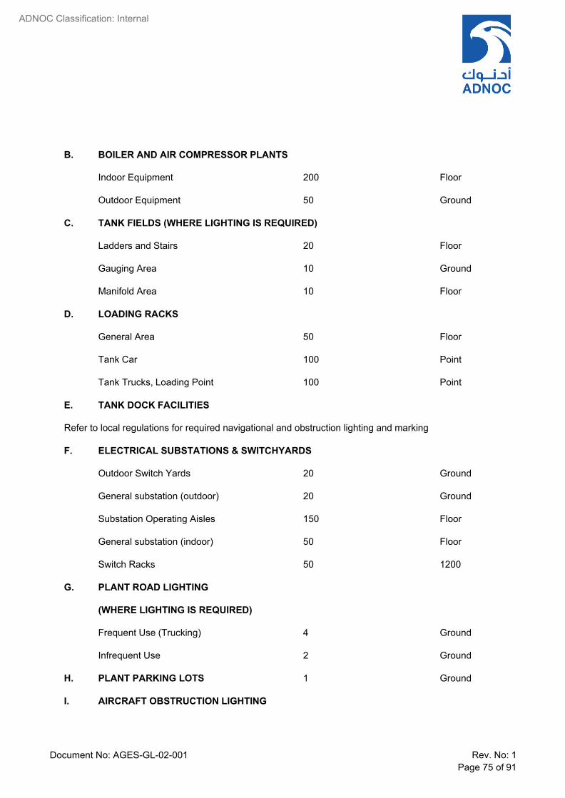
Document No: AGES-GL-02-001 Rev. No: 1 Page 75 of 91
ADNOC Classification: Internal
B. BOILER AND AIR COMPRESSOR PLANTS
Indoor Equipment 200 Floor
Outdoor Equipment 50 Ground
C. TANK FIELDS (WHERE LIGHTING IS REQUIRED)
Ladders and Stairs 20 Floor
Gauging Area 10 Ground
Manifold Area 10 Floor
D. LOADING RACKS
General Area 50 Floor
Tank Car 100 Point
Tank Trucks, Loading Point 100 Point
E. TANK DOCK FACILITIES
Refer to local regulations for required navigational and obstruction lighting and marking
F. ELECTRICAL SUBSTATIONS & SWITCHYARDS
Outdoor Switch Yards 20 Ground
General substation (outdoor) 20 Ground
Substation Operating Aisles 150 Floor
General substation (indoor) 50 Floor
Switch Racks 50 1200
G. PLANT ROAD LIGHTING
(WHERE LIGHTING IS REQUIRED)
Frequent Use (Trucking) 4 Ground
Infrequent Use 2 Ground
H. PLANT PARKING LOTS 1 Ground
I. AIRCRAFT OBSTRUCTION LIGHTING

Document No: AGES-GL-02-001 Rev. No: 1 Page 76 of 91
ADNOC Classification: Internal
Refer to local regulations for required navigational and obstruction lighting and marking
III. A.
BUILDINGS
OFFICES
Prolonged Difficult Task
(Drafting & Designing) 1000 760
Difficult Task
(Accounting, Business Machines) 750 760
Normal Office
(Reading, Files, Mail Room) 500 760
Reception Areas, Stairways, Wash Rooms 200 760
Hallways 200 Floor
Equipment & Service Rooms 150 Floor
B. LABORATORIES
Qualitative, Quantitative & Physical Test
500
900
Research. Experimental 500 900
Pilot Plant, Process and Speciality 300 Floor
ASTM Equipment Knock Test 300 Floor
Glassware, washrooms 300 900
Fume Hoods 300 900
Stock Rooms 150 Floor
C. WAREHOUSE AND STOCK ROOMS
Indoor Bulk Storage
50
Floor
Outdoor Bulk Storage 5 Ground
Large Bin Storage 50 760
Small Bin Storage 100 760

Document No: AGES-GL-02-001 Rev. No: 1 Page 77 of 91
ADNOC Classification: Internal
Small Parts Storage 200 760
Counter Tops 300 1200
D. REPAIR SHOP
Large Fabrication 300 Floor
Bench and Machine Work 500 760
Crane way, Aisles 150 Floor
Small Machine 300 760
Sheet Metal 300 760
Electrical 300 760
Instrument 500 760
E. CHANGE HOUSE
Locker Room, Shower 100 Floor
Laboratory 100 Floor
F. CLOCK HOUSE AND ENTRANCE GATEHOUSE
Card Rack and Clock Area 200 Floor
Entrance Gate, Inspection 200 Floor
General 100 Floor
G. CAFETERIA
Eating 300 760
Serving Area 300 900
Food Preparation 300 900
General Halls, etc. 100 Floor
H. GARAGE AND FIREHOUSE
Storage and Minor Repairs 100 Floor
I. FIRST AID ROOM 700 760
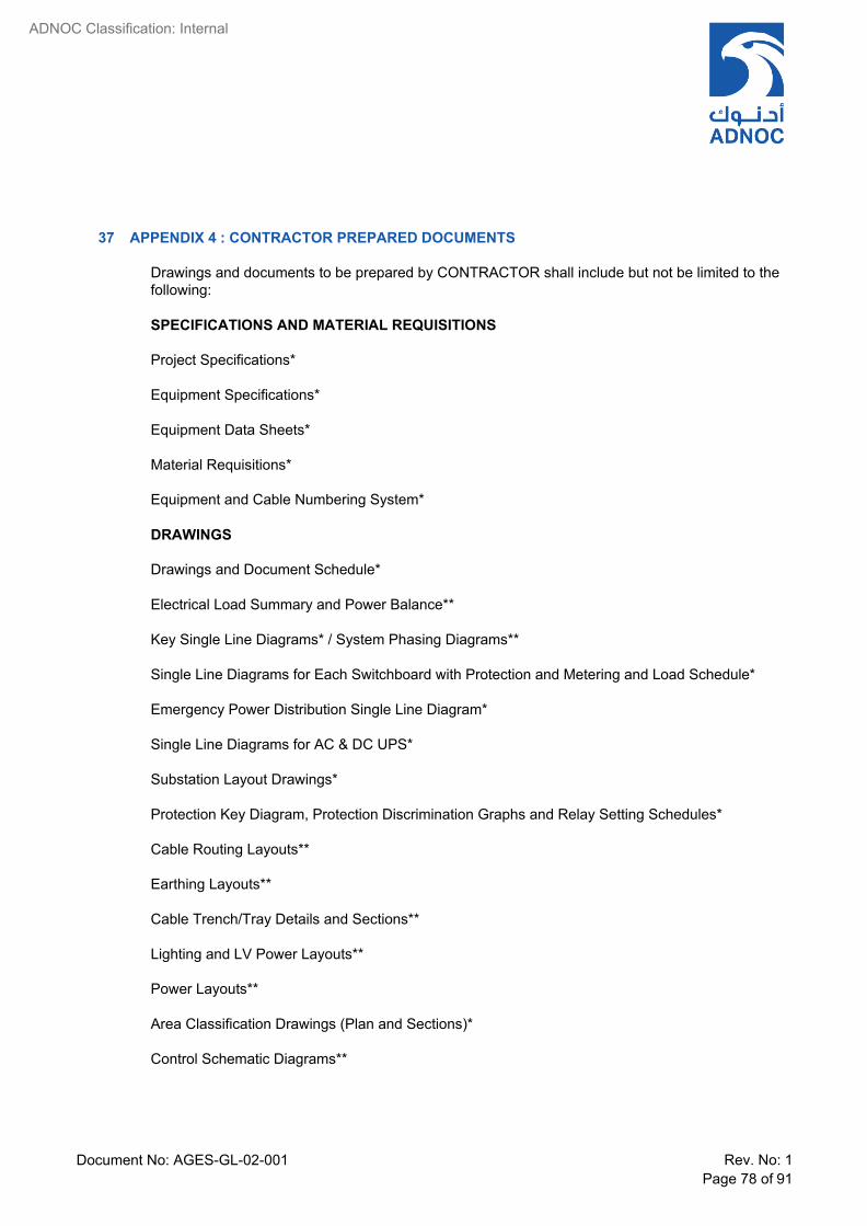
Document No: AGES-GL-02-001 Rev. No: 1 Page 78 of 91
ADNOC Classification: Internal
37 APPENDIX 4 : CONTRACTOR PREPARED DOCUMENTS
Drawings and documents to be prepared by CONTRACTOR shall include but not be limited to the following:
SPECIFICATIONS AND MATERIAL REQUISITIONS
Project Specifications*
Equipment Specifications*
Equipment Data Sheets*
Material Requisitions*
Equipment and Cable Numbering System*
DRAWINGS
Drawings and Document Schedule*
Electrical Load Summary and Power Balance**
Key Single Line Diagrams* / System Phasing Diagrams**
Single Line Diagrams for Each Switchboard with Protection and Metering and Load Schedule*
Emergency Power Distribution Single Line Diagram*
Single Line Diagrams for AC & DC UPS*
Substation Layout Drawings*
Protection Key Diagram, Protection Discrimination Graphs and Relay Setting Schedules*
Cable Routing Layouts**
Earthing Layouts**
Cable Trench/Tray Details and Sections**
Lighting and LV Power Layouts**
Power Layouts**
Area Classification Drawings (Plan and Sections)*
Control Schematic Diagrams**

Document No: AGES-GL-02-001 Rev. No: 1 Page 79 of 91
ADNOC Classification: Internal
Interconnection Diagrams**
Installation Standards (Power, Lighting, Earthing)*
Trace Heating System Layouts and Schematics**
Layouts for Cathodic Protection Systems**
Cable Schedules**
EX EQUIPMENT REGISTERS
Ex Equipment Register of CEE (Certified Electrical Equipment)** shall be developed as per Company Templates that include the following information in an excel sheet table format
• Serial No. • Location • Zone Information (Zone, Gas Group, Temperature Class) • Equipment Tag No. • Make • Model • Duty Class (continuous, intermittent, standby) • Voltage • Feeder Rating Amps • Max Amps for Exe Equipment • Enclosure Protection • Ex Class • Gas Group • Temperature Class • Certifying Authority • Certificate (Number, Validity Date) • Supplied From (Switchgear tag no., feeder No., substation No.) • Type of Inspection (Initial).
Note that initial detailed inspection shall be conducted before the plant or equipment is brought into service [§ 4.3.1 of IEC 60079-17]
• Date of Inspection Remark (condition of equipment based on initial inspection)
A separate Ex Register shall be developed for each but not limited to the following CEE Equipment: • High Voltage Motors • Low Voltage Motors • RCU and Push Buttons • Lighting Fittings • Lighting and Small Power Junction Box • Socket Outlets • Distribution Boards • MOVs • Instrument Junction Boxes • Instrument Local Control Panels

Document No: AGES-GL-02-001 Rev. No: 1 Page 80 of 91
ADNOC Classification: Internal
* Drawings/Documents to be submitted for COMPANY approval
** First Drawing/Document produced for each type to be submitted for COMPANY approval. Subsequent Drawings/Documents for COMPANY comments
STUDIES AND CALCULATIONS
System Studies (Ref. Clause 11.0 of this Specification)*
Cable Sizing Calculations*
Voltage Drop and Voltage Dip Calculations*
Illumination Level Calculations*
Motor Restart and Reacceleration Studies*
Load Shedding Studies*
Harmonic Analysis*
Power Factor Correction*
Protection Settings*
Generator / Transformer / UPS Sizing Calculations*
Earthing Design Calculations*
Cathodic Protection Design Calculations*
Fire Fighting Equipment Sizing Calculations for Substation*
MISCELLANEOUS
Field Test Procedures for Electrical Equipment and Test Record Forms*
Design Manuals**
Operation Manuals**
Spare Parts List and SPIR**
* Drawings/Documents to be submitted for COMPANY approval
** First Drawing/Document produced for each type to be submitted for COMPANY approval. Subsequent Drawings/Documents for COMPANY comments

Document No: AGES-GL-02-001 Rev. No: 1 Page 81 of 91
ADNOC Classification: Internal
38 APPENDIX 5 : CABLE SELECTION CHART FOR 415 VOLT MOTORS - DIRECT BURIED

Document No: AGES-GL-02-001 Rev. No: 1 Page 82 of 91
ADNOC Classification: Internal
39 APPENDIX 6 : LOAD SCHEDULE FORMAT

Document No: AGES-GL-02-001 Rev. No: 1 Page 83 of 91
ADNOC Classification: Internal
40 APPENDIX 7 : RESTARTING / REACCELERATION OF ESSENTIAL AUXILLIARY MOTORS
In the event of interruptions or dips in supply voltage outside the before mentioned limits, caused by disturbances in the supply grid or system short circuits etc., the following requirements shall be met:
Voltage dips resulting in consumer voltages down to 80% of rated equipment voltage shall not affect plant operations.
Voltage dips resulting in consumer terminal voltages below 80% of rated equipment voltage for duration between 0.2 and 4.5 sec shall, on voltage restoration, result in a sequential reacceleration of selected consumers.
Reacceleration schemes shall:
(i) Be configured to support process ‘essential’ load restoration
(ii) Limit maximum voltage dip at motor terminals to 20%.
(iii) Limit maximum voltage dip at switchgear bus to 10%.
(iv) Not cause unacceptable disturbances to the power system
Re-acceleration system studies shall be carried out to model:
(i) The grouping and sequence of reacceleration of motors.
(ii) The interval timing between groups of reaccelerated motors
(iii) Voltage depression at each bus during reacceleration.
System transient stability shall be verified during reacceleration.
If unacceptable motor starting voltage dips are calculated, the following solutions shall be evaluated:
(i) Stagger starting times to reduce load steps.
(ii) Decrease system source impedance to the motor busbars.
If source impedance reduction is considered switchgear shall be evaluated to ensure:
(iii) Arc energy is below acceptable value.
(iv) Commercially competitive switchgear is available from approved suppliers.
(v) Reacceleration shall be achieved by use of programmable control modules or high integrity programmable system such as the ICSS or ECS in conjunction with contactors or circuit breakers. Any other auto-restarting schemes are subject to the COMPANY’s approval.

Document No: AGES-GL-02-001 Rev. No: 1 Page 84 of 91
ADNOC Classification: Internal
(vi) Reacceleration schemes shall be verified by transient stability studies that are subject to approval by Company responsible engineer.

Document No: AGES-GL-02-001 Rev. No: 1 Page 85 of 91
ADNOC Classification: Internal
41 APPENDIX: 8 INSTRUMENT EARTHING PHILOSOPHY BLOCK DIAGRAM
(Refer STANDARD DETAIL DRAWING No. STD-1622-032 Rev.0 Electrical – Instrument Earthing Philosophy)
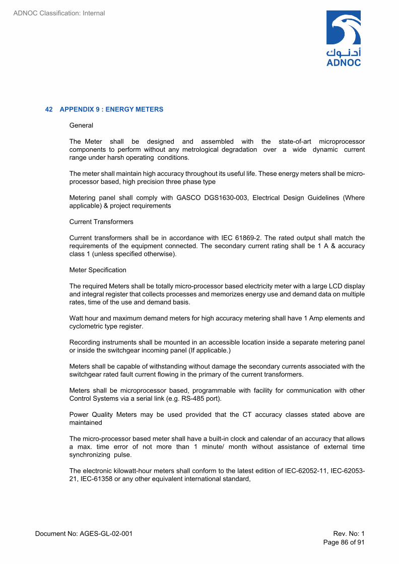
Document No: AGES-GL-02-001 Rev. No: 1 Page 86 of 91
ADNOC Classification: Internal
42 APPENDIX 9 : ENERGY METERS
General
The Meter shall be designed and assembled with the state-of-art microprocessor components to perform without any metrological degradation over a wide dynamic current range under harsh operating conditions.
The meter shall maintain high accuracy throughout its useful life. These energy meters shall be micro- processor based, high precision three phase type
Metering panel shall comply with GASCO DGS1630-003, Electrical Design Guidelines (Where applicable) & project requirements
Current Transformers
Current transformers shall be in accordance with IEC 61869-2. The rated output shall match the requirements of the equipment connected. The secondary current rating shall be 1 A & accuracy class 1 (unless specified otherwise).
Meter Specification
The required Meters shall be totally micro-processor based electricity meter with a large LCD display and integral register that collects processes and memorizes energy use and demand data on multiple rates, time of the use and demand basis.
Watt hour and maximum demand meters for high accuracy metering shall have 1 Amp elements and cyclometric type register.
Recording instruments shall be mounted in an accessible location inside a separate metering panel or inside the switchgear incoming panel (If applicable.)
Meters shall be capable of withstanding without damage the secondary currents associated with the switchgear rated fault current flowing in the primary of the current transformers.
Meters shall be microprocessor based, programmable with facility for communication with other Control Systems via a serial link (e.g. RS-485 port).
Power Quality Meters may be used provided that the CT accuracy classes stated above are maintained
The micro-processor based meter shall have a built-in clock and calendar of an accuracy that allows a max. time error of not more than 1 minute/ month without assistance of external time synchronizing pulse.
The electronic kilowatt-hour meters shall conform to the latest edition of IEC-62052-11, IEC-62053- 21, IEC-61358 or any other equivalent international standard,

Document No: AGES-GL-02-001 Rev. No: 1 Page 87 of 91
ADNOC Classification: Internal
Power quality & energy meters shall be supplied from GASCO approved suppliers for Micro- processor based relays only
Measured values
3 Ph Voltages, 3 Ph Currents, KW, KVA, KVAR, KWH, KVARH, Power factor & Frequency
Electromagnetic compatibility (EMC)
The meters shall be in accordance with the following regulations:
Electrostatic discharge according to IEC61000-4-2
Electromagnetic RF fields according to IEC61000-4-3.
Fast transient burst according to IEC61000-4-4
Fast of immunity to conducted disturbance induced by radiofrequency fields according to IEC61000- 4-6.
Surge immunity test according to IEC61000-4-5

Document No: AGES-GL-02-001 Rev. No: 1 Page 88 of 91
ADNOC Classification: Internal
43 APPENDIX 10 : MOTOR COST EVALUATION
Contractor shall evaluate motor cost bids to compare the Total All-in Cost (TAC) per annum of the motors offered using the formula given below, and using the factors and cost data stated in the requisition:
TAC = C⋅Capc + P⋅ Kot
(8760⋅ E + 12 ⋅ MDC ) 100 Eman
cost PFman
where:
C = Capital Expenditure
Capc = Capital Charge (%)
P = rated output motor (kW)
Kot = operating time per annum (%).
Typically 100% for a single motor application and 50% for dual motors
Esup = efficiency value guaranteed by the Manufacturer (%)
Ecost = energy unit cost (cost/kWh)
MDC = maximum demand charge per month (cost/kVA)
PFSup = power factor value guaranteed by the Manufacturer
Contractor shall submit Total All-in Cost calculations to Company for approval prior to motor selection.
Example of all in motor cost
P (kW)
Number of Poles
E man (at full load)
PF man (at full load)
C (USD)
Motor A 160 4 95.7 0.87 13,500
Motor B 160 4 94.6 0.87 12,500
Capc = 20%

Document No: AGES-GL-02-001 Rev. No: 1 Page 89 of 91
ADNOC Classification: Internal
(
Ecost = UDS 0.06 per kWh
MDC = USD 1/kVA
Kot = 100%
Motor A Motor B
Capital charge (USD) 2,700 2,500
Electricity cost (USD) 90,181 91,229
Total All-in Cost, TAC (USD) 92,881 93,729
In the above table the capital charge and the electricity cost are calculated as follows:
Capital Charge (USD) =
C ⋅ Capc
100
Electricity cost (USD) = P ⋅ Kot 8760 ⋅ E Eman
cost
+ 12 ⋅ MDC
PFman
In the example it is assumed that the maintenance costs are identical for both motors.
This example indicates that the Total All-in Cost of motor A is USD 848 less than that of motor B.
All other factors being equal, motor A would be the preferred option.
)

Document No: AGES-GL-02-001 Rev. No: 1 Page 90 of 91
ADNOC Classification: Internal
44 APPENDIX 11 : PREFERRED RATINGS, IMPEDANCES & VOLTAGES AND CORRELATION BETWEEN TRANSFORMER & SYSTEM VOLTAGES
1. PREFERRED RATINGS Values of rated power should be selected from the following series and their decimal multiples:
100, 125, 160, 200, 250, 315, 400, 500, 630, 800, 1000
2. IMPEDANCE VOLTAGE Unless there is an overriding design requirement, the percentage impedance voltage based on rated
power as defined in IEC 60076-5 Table 1:
Rated Power (kVA)
Impedance Voltage (%)
Up to 630 4.00
631 – 1250 5.00
1251 - 2500 6.00
2501 - 6300 7.00
6301 - 25000 8.00
25001 - 40000 10.00
40001 - 63000 11.00
63001 - 100000 12.50
Above 100000 >12.50
Impedance voltages for transformers rated above 25000 kVA shall be specified in the requisition, depending on the system design criteria.
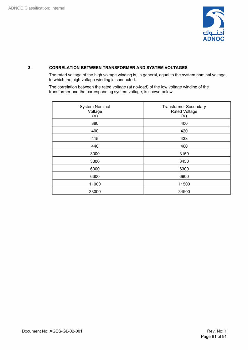
Document No: AGES-GL-02-001 Rev. No: 1 Page 91 of 91
ADNOC Classification: Internal
3. CORRELATION BETWEEN TRANSFORMER AND SYSTEM VOLTAGES The rated voltage of the high voltage winding is, in general, equal to the system nominal voltage, to which the high voltage winding is connected.
The correlation between the rated voltage (at no-load) of the low voltage winding of the transformer and the corresponding system voltage, is shown below.
System Nominal Voltage
(V)
Transformer Secondary Rated Voltage
(V)
380 400
400 420
415 433
440 460
3000 3150
3300 3450
6000 6300
6600 6900
11000 11500
33000 34500