Embed Size (px)
Citation preview

for quick sizing of Link-Seal® Modular Seals.
The contractors choice...there are no equals!
Made in U.S.A.
Information and sizing charts updated 2-08.
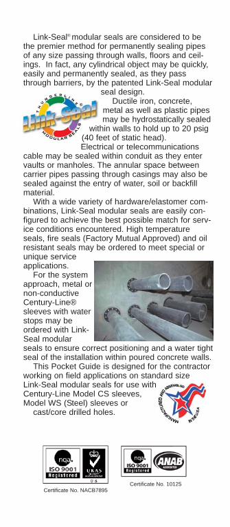
Link-Seal® modular seals are considered to bethe premier method for permanently sealing pipesof any size passing through walls, floors and ceil-ings. In fact, any cylindrical object may be quickly,easily and permanently sealed, as they passthrough barriers, by the patented Link-Seal modular
seal design.Ductile iron, concrete,
metal as well as plastic pipesmay be hydrostatically sealed
within walls to hold up to 20 psig(40 feet of static head).Electrical or telecommunications
cable may be sealed within conduit as they entervaults or manholes. The annular space betweencarrier pipes passing through casings may also besealed against the entry of water, soil or backfillmaterial.
With a wide variety of hardware/elastomer com-binations, Link-Seal modular seals are easily con-figured to achieve the best possible match for serv-ice conditions encountered. High temperatureseals, fire seals (Factory Mutual Approved) and oilresistant seals may be ordered to meet special orunique serviceapplications.
For the systemapproach, metal ornon-conductiveCentury-Line®sleeves with waterstops may beordered with Link-Seal modularseals to ensure correct positioning and a water tightseal of the installation within poured concrete walls.
This Pocket Guide is designed for the contractorworking on field applications on standard sizeLink-Seal modular seals for use withCentury-Line Model CS sleeves,Model WS (Steel) sleeves or
cast/core drilled holes.
Certificate No. NACB7895Certificate No. 10125

Table of Contents
Useful Information Prior to Sizing/InstallationSuggested Pipe O.D. Range 2Minimum Required Seating Width 2Frequently Asked Questions 3
SizingSizing Charts for Standard Pipe Century-Line Sleeves 4-9Sizing Charts for Standard Pipe WS Steel Wall Sleeves 10-15Sizing Charts for Standard Pipe Cast/Core Bit Drilled Hole 16-21
Installation TechniquesLink-Seal® Modular Seal Installation 22-23Century-Line® Sleeve Installation 24-26Cell-Cast® Disk Installation 26-28
For Complete Product Information use the Link-SealEngineering Manual or Selection Guide. Availableon-line at www.linkseal.com
Updated engineering catalogs, literature, CADDrawings, installation videos, sizing program andinstallation techniques are available on-line at:www.linkseal.com
Performance data included in this manual isintended for guideline purposes only.Performance suitability for any specific applica-tion should be determined by the user. Variationin temperature, pressure, concentration or mix-tures acting synergistically may preclude recom-mended service use.

* =
Whe
neve
r po
ssib
le u
se th
icke
rlin
ks, s
uch
as th
e LS
-400
, LS-
475
orLS
-500
ser
ies
to p
rovi
de m
ore
leew
ay.
Suggested Pipe O.D. Range
Link-Seal® Model Minimum RequiredSelected for Penetration Seating WidthLS-200/275 2.25”LS-300/315 3.00”LS-325/340/360 4.00”LS-400/410/425/475 5.00”LS-500/525/575 5.00”LS-600/650 6.00”
2

3
Frequently Asked Questions
1) Q - How do I install Link-Seal® modular seals over weld-bead?A - Weld-beads and all otherirregularities on the pipe oropening should be addressed inaccordance with the manufac-turer’s and/or project engineer’ssuggestions to provide a round,smooth and clean surface forLink-Seal installation.
2) Q - How much angular pipemovement will Link-Seal modu-lar seals allow and still maintaina seal?A - Link-Seal modular sealsmay allow angular pipe move-ment or misalignment depend-ing on the ratio of annular spaceof the penetration to theexpanded range of the Link-Seal model sized for the pene-tration. Please call PSI for moreinformation.
3) Q - Is it necessary to useWS or CS sleeves wheninstalling Link-Seal modularseals?A - WS model steel and CSmodel plastic sleeves are spe-cially designed for use withLink-Seal modular seals. Wheninstalled with Link-Seal modularseals these sleeves provide thebest possible assurance of aquality wall penetration system.
4) Q - Sometimes wheninstalling a belt of Link-Sealmodular seals, it hangs looseon the pipe even though all mysizing calculations are correct.Why does it appear that I havetoo many links?A - Link-Seal modular seals arebasically sized to fit the opening,not the pipe. Use the assem-blies suggested by the charts orcalculation. It may not look right,
but it will fit.
5) Q - Can Link-Seal modularseals be used for penetrationswhere the pipe is off-center tothe opening?A - Centering is very important.Contact PSI for more informa-tion.
6) Q - Is it necessary to use riserclamps, pipe saddles and hang-er supports with Link-Seal mod-ular seals?A - Designed as a penetrationseaL, Link-Seal modular sealsare not intended to be a structur-al support. Standard pipe hangerpractice should always beapplied.
7) Q - What tools are required toinstall Link-Seal modular seals?A - A socket or offset wrenchwith 5/16”, 1/2”, 3/8”, 9/16”, 3/4”& 1-3/16” sockets will handle allinstallations. A low speed (450RPM or less) power tool is sug-gested for multiple installations toincrease efficiency. (see nextquestion)
8) Q - Can I use power toolswhen installing Link-Seal modu-lar seals with 316 stainless steelbolts?A - No, please see suggested installation techniques.
9) Q - Can Link-Seal modularseals be used with manholevault installed thimbles, notsleeves?A - No, only if the area creates apenetration cylinder, such thatthe axis of the cylinder is parallelto the axis of the pipe goingthrough it.

How to Order:Using the Provided Sizing Charts1. Determine Link-Seal® modular seal model to be
used (See Link-Seal Selection Guide or EngineeringManual for technical information).
2. Locate charts on pages 6 through 9 that corre-sponds to the type and size pipe being used.
3. Verify that your pipe O.D. matches the actualoutside diameter shown on the chart.
4. To order Link-Seal modular seals choose Link-Seal modular seal size (from SIZE column),Link-Seal modular seal model (C, S-316, L, LS-316, O, OS-316, T or FD/FS) and indicatenumber of links required per seal (from LINKSPER SEAL column).[Example: LS-575-C-10]
5. To order corresponding Century-Line sleevesindicate model number (from MODEL NUMBERcolumn), length of sleeve and quantity required.[CS Example: CS-10-12”-1]
Note: Contact PSI (1-800-423-2410) or your local dis-tributor if your pipe sizing solution is not listed inthe provided charts.
Century-Line® SleevesModel CS (16” length)Weights and Dimensional Data
MODEL I.D. (In.) I.D. (mm) lbs. Kg.CS-2 1.98 50.3 0.70 0.32CS-3 2.94 74.7 1.30 0.59CS-3-1/2 3.38 85.9 1.50 0.68CS-4 4.03 102.4 2.00 0.90CS-5 5.14 130.6 2.80 1.27CS-6 6.14 156.0 3.60 1.63CS-8 8.21 208.5 4.80 2.18CS-10 10.19 258.8 6.40 2.90CS-12 12.26 311.4 7.20 3.27CS-14 14.14 359.2 11.20 5.08CS-16 16.18 411.0 12.00 5.44CS-18 17.45 443.2 15.50 7.03CS-20 19.12 485.6 17.50 7.94CS-22 20.32 516.1 21.00 9.53CS-24 22.76 578.1 22.00 9.98CS-25 24.81 630.2 23.00 10.43
4
Cen
tury
-Lin
e®Sl
eeve
s

Sizing Charts for Standard Pipe whenusing Link-Seal® Modular Seals andCentury-Line® Sleeves with:• SDR-35 Gravity Sewer Pipe• Steel and Plastic Pipe with Same
Outside Diameter (IPS)• Ductile Iron Pipe (DIPS, AWWA-C900,
AWWA-C905, PVC Water Pipe)• Copper Tubing• Cast Iron Soil Pipe (Extra Heavy)• Cast Iron Soil Pipe (Service Weight)• Electrical Metallic Tubing (EMT) • Thin Wall Intermediate Metal Conduit (IMC)• Rigid (RSC), Aluminum (ASC), Galvanized
(GSC), Non-Metallic Conduit (NRC)
Link-Seal® Modular Seal Models:EPDM Seal ElementsModel C = Standard EPDM (black)Model L = Low Durometer EPDM (blue)Model S-316 = 316 Stainless Steel HardwareModel LS-316 = 316 Stainless Steel Hardware
Nitrile Seal ElementsModel O = Standard Nitrile (green) Oil ResistantModel OS-316 = with 316 Stainless Steel Hardware
Silicone Seal ElementsModel T = Silicone (grey) High Temp. Model FD/FS = Double Silicone Seal
5
Century-Line
®Sleeves
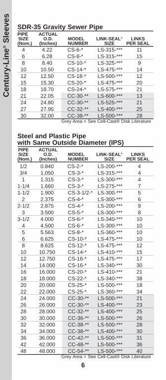
SDR-35 Gravity Sewer PipePIPE ACTUALSIZE O.D. MODEL LINK-SEAL® LINKS(Nom.) (Inches) NUMBER SIZE PER SEAL
4 4.22 CS-6-* LS-315-*** 116 6.28 CS-8-* LS-315-*** 158 8.40 CS-10-* LS-325-*** 9
10 10.50 CS-14-* LS-475-*** 1412 12.50 CS-18-* LS-500-*** 1215 15.30 CS-20-* LS-475-*** 2018 18.70 CS-24-* LS-575-*** 2121 22.05 CC-30-** LS-600-*** 1324 24.80 CC-30-** LS-525-*** 2127 27.95 CC-32-** LS-400-*** 2530 32.00 CC-38-** LS-500-*** 28
Grey Area = See Cell-Cast® Disk Literature
Steel and Plastic Pipewith Same Outside Diameter (IPS)PIPE ACTUALSIZE O.D. MODEL LINK-SEAL® LINKS(Nom.) (Inches) NUMBER SIZE PER SEAL1/2 0.840 CS-2-* LS-200-*** 43/4 1.050 CS-3-* LS-315-*** 41 1.315 CS-3-* LS-300-*** 4
1-1/4 1.660 CS-3-* LS-275-*** 71-1/2 1.900 CS-3-1/2-* LS-300-*** 5
2 2.375 CS-4-* LS-300-*** 62-1/2 2.875 CS-4-* LS-200-*** 9
3 3.500 CS-5-* LS-300-*** 83-1/2 4.000 CS-6-* LS-340-*** 10
4 4.500 CS-6-* LS-300-*** 105 5.563 CS-8-* LS-360-*** 106 6.625 CS-10-* LS-475-*** 108 8.625 CS-12-* LS-475-*** 12
10 10.750 CS-14-* LS-410-*** 1512 12.750 CS-16-* LS-475-*** 1714 14.000 CS-16-* LS-340-*** 3016 16.000 CS-20-* LS-410-*** 2118 18.000 CS-22-* LS-340-*** 3820 20.000 CS-25-* LS-500-*** 1822 22.000 CS-25-* LS-360-*** 3424 24.000 CC-30-** LS-500-*** 2126 26.000 CC-30-** LS-400-*** 2328 28.000 CC-32-** LS-400-*** 2530 30.000 CC-36-** LS-500-*** 2632 32.000 CC-38-** LS-500-*** 2834 34.000 CC-38-** LS-400-*** 3036 36.000 CC-42-** LS-500-*** 3142 42.000 CC-48-** LS-500-*** 3648 48.000 CC-54-** LS-500-*** 40
Grey Area = See Cell-Cast® Disk Literature
6
Cen
tury
-Lin
e®Sl
eeve
s

Ductile Iron Pipe (DIPS, AWWA-C900,AWWA-C905, PVC Water Pipe)PIPE ACTUALSIZE O.D. MODEL LINK-SEAL® LINKS(Nom.) (Inches) NUMBER SIZE PER SEAL
2 2.500 CS-4-* LS-300-*** 62-1/4 2.750 CS-4-* LS-275-*** 10
3 3.960 CS-6-* LS-340-*** 104 4.800 CS-8-* LS-475-*** 86 6.900 CS-10-* LS-475-*** 108 9.050 CS-12-* LS-400-*** 9
10 11.100 CS-14-* LS-410-*** 1512 13.200 CS-18-* LS-575-*** 1514 15.300 CS-20-* LS-475-*** 2016 17.400 CS-22-* LS-360-*** 2818 19.500 CS-24-* LS-410-*** 2520 21.600 CS-25-* LS-400-*** 2024 25.800 CC-30-** LS-400-*** 2330 32.000 CC-38-** LS-500-*** 2836 38.300 CC-44-** LS-500-*** 3342 44.500 CC-50-** LS-500-*** 3848 50.800 CC-56-** LS-500-*** 43
Grey Area = See Cell-Cast® Disk Literature
Copper TubingPIPE ACTUALSIZE) O.D. MODEL LINK-SEAL® LINKS
(Nom.) (Inches) NUMBER SIZE PER SEAL1/2 0.625 CS-2-* LS-275-*** 43/4 0.875 CS-2-* LS-200-*** 41 1.125 CS-3-* LS-315-*** 4
1-1/4 1.375 CS-3-* LS-275-*** 81-1/2 1.625 CS-3-* LS-275-*** 8
2 2.125 CS-4-* LS-315-*** 62-1/2 2.625 CS-4-* LS-275-*** 12
3 3.125 CS-5-* LS-340-*** 84 4.125 CS-6-* LS-315-*** 116 6.125 CS-8-* LS-315-*** 158 8.125 CS-12-* LS-575-*** 10
10 10.125 CS-12-* LS-340-*** 2212 12.125 CS-16-* LS-575-*** 14
NOTES:* = Specify sleeve length in inches ** = See Cell-Cast Literature*** = Specify LS Model C, S-316, L...etc when ordering(Example LS-475-C-17). Technically there is no limit to the pipe size that can be sealedusing Link-Seal® modular seals. Please contact factory for sizesnot listed and for CS model plastic sleeves for walls less than 8”thick.
7
Century-Line
®Sleeves
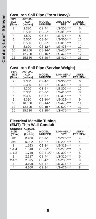
Cast Iron Soil Pipe (Service Weight)PIPE ACTUALSIZE O.D. MODEL LINK-SEAL® LINKS
(Nom.) (Inches) NUMBER SIZE PER SEAL2 2.300 CS-4-* LS-300-*** 63 3.300 CS-5-* LS-300-*** 84 4.300 CS-6-* LS-300-*** 105 5.300 CS-8-* LS-410-*** 86 6.300 CS-8-* LS-315-*** 158 8.380 CS-10-* LS-325-*** 9
10 10.500 CS-14-* LS-475-*** 1412 12.500 CS-18-* LS-500-*** 1215 15.620 CS-20-* LS-475-*** 20
Electrical Metallic Tubing(EMT) Thin Wall ConduitCONDUIT ACTUALSIZE O.D. MODEL LINK-SEAL® LINKS(Nom.) (Inches) NUMBER SIZE PER SEAL1/2 0.706 CS-2-* LS-275-*** 43/4 0.922 CS-2-* LS-200-*** 41 1.163 CS-3-* LS-315-*** 4
1-1/4 1.510 CS-3-* LS-275-*** 81-1/2 1.740 CS-3-1/2-* LS-300-*** 5
2 2.197 CS-4-* LS-315-*** 62-1/2 2.875 CS-4-* LS-200-*** 9
3 3.500 CS-5-* LS-315-*** 94 4.500 CS-8-* LS-475-*** 8
Cast Iron Soil Pipe (Extra Heavy)PIPE ACTUALSIZE O.D. MODEL LINK-SEAL® LINKS(Nom.) (Inches) NUMBER SIZE PER SEAL
2 2.380 CS-4-* LS-300-*** 63 3.500 CS-5-* LS-315-*** 94 4.500 CS-8-* LS-475-*** 85 5.500 CS-8-* LS-360-*** 106 6.500 CS-8-* LS-315-*** 158 8.620 CS-12-* LS-475-*** 12
10 10.750 CS-14-* LS-410-*** 1512 12.750 CS-16-* LS-475-*** 1715 15.880 CS-20-* LS-410-*** 21
8
Cen
tury
-Lin
e®Sl
eeve
s

Rigid (RSC), Aluminum (ASC), Galvanized(GSC), Non-Metallic Conduit (NRC)CONDUIT ACTUALSIZE O.D. MODEL LINK-SEAL® LINKS
(Nom.) (Inches) NUMBER SIZE PER SEAL1/2 0.840 CS-2-* LS-200-*** 43/4 1.050 CS-3-* LS-315-*** 41 1.315 CS-3-* LS-300-*** 4
1-1/4 1.660 CS-3-* LS-275-*** 71-1/2 1.900 CS-3-1/2-* LS-300-*** 5
2 2.375 CS-4-* LS-300-*** 62-1/2 2.875 CS-4-* LS-200-*** 9
3 3.500 CS-5-* LS-300-*** 83-1/2 4.000 CS-6-* LS-340-*** 10
4 4.500 CS-6-* LS-300-*** 105 5.563 CS-8-* LS-360-*** 106 6.625 CS-10-* LS-475-*** 10
Intermediate Metal Conduit (IMC)CONDUIT ACTUALSIZE O.D. MODEL LINK-SEAL® LINKS
(Nom.) (Inches) NUMBER SIZE PER SEAL1/2 0.815 CS-2-* LS-200-*** 43/4 1.029 CS-2-* LS-200-*** 41 1.290 CS-3-1/2-* LS-315-*** 5
1-1/4 1.638 CS-3-* LS-275-*** 81-1/2 1.883 CS-3-1/2-* LS-300-*** 5
2 2.360 CS-4-* LS-300-*** 62-1/2 2.857 CS-4-* LS-200-*** 9
3 3.476 CS-5-* LS-315-*** 93-1/2 3.970 CS-6-* LS-340-*** 10
4 4.466 CS-6-* LS-315-*** 11
NOTES:* = Specify sleeve length in inches *** = Specify LS Model C, S-316, L...etc when ordering(Example LS-475-C-17). Technically there is no limit to the pipe size that can be sealedusing Link-Seal® modular seals. Please contact factory for sizesnot listed and for CS model plastic sleeves for walls less than 8”thick.
9
Century-Line
®Sleeves

Model WS (12” length)MODEL I.D. lbs. Kg.WS-2-15-S-12 2.07 5.53 2.51WS-2-1/2-20-S-12 2.47 7.91 3.58WS-3-21-S-12 3.07 9.93 4.51WS-3-1/2-22-S-12 3.55 11.70 5.31WS-4-23-S-12 4.03 13.61 6.17WS-5-25-S-12 5.05 17.91 8.12WS-6-28-S-12 6.07 22.73 10.31ws-6-18-S-12 6.25 14.82 6.72WS-8-32-S-12 7.98 33.55 15.22ws-8-18-S-12 8.25 21.94 9.95WS-10-36-S-12 10.02 46.12 20.92ws-10-25-S-12 10.25 33.67 15.27WS-12-37-S-12 12.00 60.14 27.28WS-14-37-S-12 13.25 62.04 28.14WS-16-37-S-12 15.25 71.04 32.22WS-18-37-S-12 17.25 79.98 36.28WS-20-37-S-12 19.25 90.00 40.82WS-22-37-S-12 21.25 98.00 44.45WS-24-37-S-12 23.25 107.00 48.53
10
How to Order:Using the Provided Sizing Charts1. Determine Link-Seal® modular seal model to be
used (See Link-Seal Selection Guide or EngineeringManual for technical information).
2. Locate charts on pages 12 through 15 that cor-responds to the type and size pipe being used.
3. Verify that your pipe O.D. matches the actualoutside diameter shown on the chart.
4. To order Link-Seal modular seals choose Link-Seal modular seal size (from SIZE column),Link-Seal modular seal model (C, S-316, L, LS-316, O, OS-316, T or FD/FS) and indicate num-ber of links required per seal (from LINKS PERSEAL column). [Example: LS-575-C-10]
5. To order corresponding WS Steel sleeves indi-cate model number (from MODEL NUMBERcolumn), length of sleeve and quantity required.[WS Example: WS-10-12”-1]
Note: Contact PSI (1-800-423-2410) oryour local distributor if your pipe sizingsolution is not listed in the providedcharts.
WS
Stee
l Sle
eves

Link-Seal® Modular Seal Models:EPDM Seal ElementsModel C = Standard EPDM (black)Model L = Low Durometer EPDM (blue)Model S-316 = 316 Stainless Steel HardwareModel LS-316 = 316 Stainless Steel Hardware
Nitrile Seal ElementsModel O = Standard Nitrile (green) Oil ResistantModel OS-316 = with 316 Stainless Steel Hardware
Silicone Seal ElementsModel T = Silicone (grey) High Temp. Model FD/FS = Double Silicone Seal
Sizing Charts for Standard Pipe whenusing Link-Seal® Modular Seals and WSSteel Sleeves with:• SDR-35 Gravity Sewer Pipe• Steel and Plastic Pipe with Same
Outside Diameter (IPS)• Ductile Iron Pipe (DIPS, AWWA-C900,
AWWA-C905, PVC Water Pipe)• Copper Tubing• Cast Iron Soil Pipe (Extra Heavy)• Cast Iron Soil Pipe (Service Weight)• Electrical Metallic Tubing (EMT) • Thin Wall Intermediate Metal Conduit (IMC)• Rigid (RSC), Aluminum (ASC), Galvanized
(GSC), Non-Metallic Conduit (NRC)
11
Note: WS sizes thru. 10” are schedule 40. WSsizes 12” and up have a standard .375” wallthickness.
WS Steel Sleeves

SDR-35 Gravity Sewer PipePIPE ACTUALSIZE O.D. MODEL LINK-SEAL® LINKS(Nom.) (Inches) NUMBER SIZE PER SEAL
4 4.22 WS-6-28-S-* LS-315-*** 106 6.28 WS-8-32-S-* LS-315-*** 158 8.40 WS-10-36-S-* LS-315-*** 19
10 10.50 WS-14-37-S-* LS-360-*** 1712 12.50 WS-16-37-S-* LS-360-*** 2015 15.30 WS-20-37-S-* LS-575-*** 1718 18.70 WS-22-37-S-* LS-360-*** 2921 22.05 WS-26-37-S-* LS-475-*** 2824 24.80 WS-28-37-S-* LS-425-*** 2227 27.95 WS-32-37-S-* LS-400-*** 2530 32.00 WS-36-37-S-* LS-400-*** 29
Steel and Plastic Pipewith Same Outside Diameter (IPS)PIPE ACTUALSIZE O.D. MODEL LINK-SEAL® LINKS(Nom.) (Inches) NUMBER SIZE PER SEAL1/2 0.840 WS-2-15-S-* LS-275-*** 53/4 1.050 WS-2-1/2-20-S-* LS-275-*** 61 1.315 WS-2-1/2-20-S-* LS-200-*** 5
1-1/4 1.660 WS-3-21-S-* LS-275-*** 81-1/2 1.900 WS-3-21-S-* LS-200-*** 7
2 2.375 WS-3-1/2-22-S-* LS-200-*** 82-1/2 2.875 WS-4-23-S-* LS-200-*** 9
3 3.500 WS-6-28-S-* LS-360-*** 73-1/2 4.000 WS-6-28-S-* LS-340-*** 9
4 4.500 WS-6-28-S-* LS-300-*** 105 5.563 WS-8-32-S-* LS-340-*** 136 6.625 WS-10-36-S-* LS-475-*** 108 8.625 WS-12-37-S-* LS-475-*** 12
10 10.750 WS-14-37-S-* LS-425-*** 1012 12.750 WS-16-37-S-* LS-425-*** 1214 14.000 WS-18-37-S-* LS-475-*** 1816 16.000 WS-20-37-S-* LS-475-*** 2118 18.000 WS-22-37-S-* LS-475-*** 2320 20.000 WS-24-37-S-* LS-475-*** 2522 22.000 WS-26-37-S-* LS-475-*** 2824 24.000 WS-28-37-S-* LS-475-*** 3026 26.000 WS-30-37-S-* LS-400-*** 2328 28.000 WS-32-37-S-* LS-400-*** 2530 30.000 WS-34-37-S-* LS-400-*** 2732 32.000 WS-36-37-S-* LS-400-*** 2934 34.000 WS-40-37-S-* LS-500-*** 2936 36.000 WS-42-37-S-* LS-500-*** 3142 42.000 WS-48-37-S-* LS-500-*** 3648 48.000 WS-53-37-S-* LS-525-*** 40
12
WS
Stee
l Sle
eves

Copper TubingPIPE ACTUALSIZE) O.D. MODEL LINK-SEAL® LINKS
(Nom.) (Inches) NUMBER SIZE PER SEAL1/2 0.625 WS-2-15-S-* LS-275-*** 53/4 0.875 WS-2-1/2-20-S-* LS-275-*** 61 1.125 WS-2-1/2-20-S-* LS-275-*** 6
1-1/4 1.375 WS-2-1/2-20-S-* LS-200-*** 51-1/2 1.625 WS-3-21-S-* LS-275-*** 7
2 2.125 WS-3-1/2-22-S-* LS-275-*** 102-1/2 2.625 WS-4-23-S-* LS-275-*** 11
3 3.125 WS-5-25-S-* LS-315-*** 84 4.125 WS-6-28-S-* LS-315-*** 106 6.125 WS-8-32-S-* LS-315-*** 158 8.125 WS-10-36-S-* LS-315-*** 19
10 10.125 WS-14-37-S-* LS-410-*** 1412 12.125 WS-16-37-S-* LS-410-*** 16
Ductile Iron Pipe (DIPS, AWWA-C900,AWWA-C905, PVC Water Pipe)PIPE ACTUALSIZE O.D. MODEL LINK-SEAL® LINKS(Nom.) (Inches) NUMBER SIZE PER SEAL
2 2.500 WS-3-1/2-22-S-* LS-200-*** 82-1/4 2.750 WS-4-23-S-* LS-200-*** 9
3 3.960 WS-6-28-S-* LS-340-*** 94 4.800 WS-8-32-S-* LS-410-*** 76 6.900 WS-10-36-S-* LS-410-*** 108 9.050 WS-12-37-S-* LS-400-*** 9
10 11.100 WS-14-37-S-* LS-340-*** 2412 13.200 WS-18-37-S-* LS-475-*** 1814 15.300 WS-20-37-S-* LS-575-*** 1716 17.400 WS-22-37-S-* LS-475-*** 2318 19.500 WS-24-37-S-* LS-575-*** 2120 21.600 WS-26-37-S-* LS-475-*** 2724 25.800 WS-30-37-S-* LS-400-*** 2330 32.000 WS-36-37-S-* LS-400-*** 2936 38.300 WS-44-1/2-37-S-*LS-500-*** 3342 44.500 WS-50-37-S-* LS-500-*** 3848 50.800 WS-57-37-S-* LS-500-*** 43
NOTES:* = Specify sleeve length in inches *** = Specify LS Model C, S-316, L...etc when ordering(Example LS-475-C-17). Technically there is no limit to the pipe size that can be sealedusing Link-Seal® modular seals. Please contact factory for sizesnot listed and for CS model plastic sleeves for walls less than 8”thick.
13
WS Steel Sleeves

Cast Iron Soil Pipe (Extra Heavy)PIPE ACTUALSIZE O.D. MODEL LINK-SEAL® LINKS(Nom.) (Inches) NUMBER SIZE PER SEAL
2 2.380 WS-3-1/2-22-S-* LS-200-*** 83 3.500 WS-6-28-S-* LS-360-*** 74 4.500 WS-6-28-S-* LS-300-*** 105 5.500 WS-8-32-S-* LS-340-*** 136 6.500 WS-10-36-S-* LS-475-*** 108 8.620 WS-12-37-S-* LS-475-*** 12
10 10.750 WS-14-37-S-* LS-425-*** 1012 12.750 WS-16-37-S-* LS-425-*** 1215 15.880 WS-20-37-S-* LS-475-*** 20
Cast Iron Soil Pipe (Service Weight)PIPE ACTUALSIZE O.D. MODEL LINK-SEAL® LINKS(Nom.) (Inches) NUMBER SIZE PER SEAL
2 2.300 WS-4-23-S-* LS-315-*** 63 3.300 WS-6-28-S-* LS-360-*** 74 4.300 WS-6-28-S-* LS-315-*** 105 5.300 WS-8-32-S-* LS-360-*** 96 6.300 WS-8-32-S-* LS-315-*** 158 8.380 WS-10-36-S-* LS-315-*** 19
10 10.500 WS-14-37-S-* LS-360-*** 1712 12.500 WS-16-37-S-* LS-360-*** 2015 15.620 WS-20-37-S-* LS-475-*** 20
Electrical Metallic Tubing (EMT) Thin WallCONDUIT ACTUALSIZE O.D. MODEL LINK-SEAL® LINKS
(Nom.) (Inches) NUMBER SIZE PER SEAL1/2 0.706 WS-2-15-S-* LS-275-*** 53/4 0.922 WS-2-1/2-20-S-* LS-275-*** 61 1.163 WS-2-1/2-20-S-* LS-275-*** 6
1-1/4 1.510 WS-3-21-S-* LS-275-*** 61-1/2 1.740 WS-3-21-S-* LS-275-*** 8
2 2.197 WS-3-1/2-22-S-* LS-275-*** 102-1/2 2.875 WS-4-23-S-* LS-200-*** 9
3 3.500 WS-6-28-S-* LS-360-*** 74 4.500 WS-6-28-S-* LS-300-*** 10
14
WS
Stee
l Sle
eves

Rigid (RSC), Aluminum (ASC), Galvanized(GSC), Non-Metallic Conduit (NRC)CONDUIT ACTUALSIZE O.D. MODEL LINK-SEAL® LINKS
(Nom.) (Inches) NUMBER SIZE PER SEAL1/2 0.840 WS-2-15-S-* LS-275-*** 53/4 1.050 WS-2-1/2-20-S-* LS-275-*** 61 1.315 WS-2-1/2-20-S-* LS-200-*** 5
1-1/4 1.660 WS-3-21-S-* LS-275-*** 81-1/2 1.900 WS-3-21-S-* LS-200-*** 7
2 2.375 WS-3-1/2-22-S-* LS-200-** 82-1/2 2.875 WS-4-23-S-* LS-200-*** 9
3 3.500 WS-6-28-S-* LS-360-*** 73-1/2 4.000 WS-6-28-S-* LS-340-*** 9
4 4.500 WS-6-28-S-* LS-300-*** 105 5.563 WS-8-32-S-* LS-340-*** 136 6.625 WS-10-36-S-* LS-475-*** 10
Intermediate Metal Conduit (IMC)CONDUIT ACTUALSIZE O.D. MODEL LINK-SEAL® LINKS
(Nom.) (Inches) NUMBER SIZE PER SEAL1/2 0.815 WS-2-15-S-* LS-275-*** 53/4 1.029 WS-2-1/2-20-S-* LS-275-*** 61 1.290 WS-2-1/2-20-S-* LS-200-*** 5
1-1/4 1.638 WS-3-21-S-* LS-275-*** 81-1/2 1.883 WS-3-21-S-* LS-200-*** 7
2 2.360 WS-3-1/2-22-S-* LS-200-*** 82-1/2 2.857 WS-4-23-S-* LS-200-*** 9
3 3.476 WS-6-28-S-* LS-360-*** 73-1/2 3.970 WS-6-28-S* LS-340-*** 9
4 4.466 WS-6-28-S-* LS-300-*** 10
NOTES:* = Specify sleeve length in inches *** = Specify LS Model C, S-316, L...etc when ordering(Example LS-475-C-17). Technically there is no limit to the pipe size that can be sealedusing Link-Seal® modular seals. Please contact factory for sizesnot listed and for CS model plastic sleeves for walls less than 8”thick.
15
WS Steel Sleeves

16
How to Order:Using the Provided Sizing Charts1. Determine Link-Seal® modular seal model to be
used (See Link-Seal Selection Guide or EngineeringManual for technical information).
2. Locate charts on pages 18 through 21 that cor-responds to the type and size pipe being used.
3. Verify that your pipe O.D. matches the actualoutside diameter shown on the chart.
4. To order Link-Seal modular seals choose Link-Seal modular seal size (from SIZE column),Link-Seal modular seal model (C, S-316, L, LS-316, O, OS-316, T or FD/FS) and indicatenumber of links required per seal (from LINKSPER SEAL column).[Example: LS-575-C-10]
Note: Contact PSI (1-800-423-2410) or your local dis-tributor if your pipe sizing solution is not listed inthe provided charts.
Cas
t or
Cor
e B
it D
rille
d H
oles

Link-Seal® Modular Seal Models:EPDM Seal ElementsModel C = Standard EPDM (black)Model L = Low Durometer EPDM (blue)Model S-316 = 316 Stainless Steel HardwareModel LS-316 = 316 Stainless Steel Hardware
Nitrile Seal ElementsModel O = Standard Nitrile (green) Oil ResistantModel OS-316 = with 316 Stainless Steel Hardware
Silicone Seal ElementsModel T = Silicone (grey) High Temp. Model FD/FS = Double Silicone Seal
Sizing Charts for Standard Pipe whenusing Link-Seal® Modular Seals in Cast orCore Bit Drilled Holes:• SDR-35 Gravity Sewer Pipe• Steel and Plastic Pipe with Same
Outside Diameter (IPS)• Ductile Iron Pipe (DIPS, AWWA-C900,
AWWA-C905, PVC Water Pipe)• Copper Tubing• Cast Iron Soil Pipe (Extra Heavy)• Cast Iron Soil Pipe (Service Weight)• Electrical Metallic Tubing (EMT) • Thin Wall Intermediate Metal Conduit (IMC)• Rigid (RSC), Aluminum (ASC), Galvanized
(GSC), Non-Metallic Conduit (NRC)
17
Cast or C
ore Bit D
rilled Holes

Steel and Plastic Pipewith Same Outside Diameter (IPS)PIPE ACTUALSIZE O.D. HOLE LINK-SEAL® LINKS(Nom.) (Inches) I.D. SIZE PER SEAL1/2 0.840 2.000 LS-200-*** 43/4 1.050 3.000 LS-315-*** 41 1.315 3.000 LS-300-*** 4
1-1/4 1.660 3.000 LS-275-*** 81-1/2 1.900 4.000 LS-315-*** 6
2 2.375 4.000 LS-300-*** 62-1/2 2.875 4.000 LS-200-*** 9
3 3.500 5.000 LS-300-*** 83-1/2 4.000 6.000 LS-315-*** 10
4 4.500 6.000 LS-300-*** 105 5.563 8.000 LS-340-*** 136 6.625 10.000 LS-475-*** 108 8.625 12.000 LS-475-*** 12
10 10.750 14.000 LS-475-*** 1412 12.750 16.000 LS-475-*** 1714 14.000 18.000 LS-575-*** 1616 16.000 20.000 LS-575-*** 1818 18.000 22.000 LS-575-*** 2020 20.000 24.000 LS-475-*** 2622 22.000 26.000 LS-575-*** 2424 24.000 28.000 LS-475-*** 3126 26.000 30.000 LS-575-*** 2828 28.000 32.000 LS-575-*** 3030 30.000 34.000 LS-575-*** 3232 32.000 36.000 LS-575-*** 3434 34.000 38.000 LS-575-*** 3636 36.000 40.000 LS-575-*** 3842 42.000 46.000 LS-575-*** 4448 48.000 52.000 LS-575-*** 50
SDR-35 Gravity Sewer PipePIPE ACTUALSIZE O.D. HOLE LINK-SEAL® LINKS(Nom.) (Inches) I.D. SIZE PER SEAL
4 4.22 6.000 LS-315-*** 106 6.28 8.000 LS-315-*** 158 8.40 12.000 LS-475-*** 12
10 10.50 14.000 LS-475-*** 1412 12.50 16.000 LS-475-*** 1715 15.30 18.000 LS-360-*** 2418 18.70 22.000 LS-475-*** 2421 22.05 26.000 LS-575-*** 2424 24.80 28.000 LS-475-*** 3127 27.95 32.000 LS-575-*** 3030 32.00 36.000 LS-575-*** 34
18Cas
t or
Cor
e B
it D
rille
d H
oles

Copper TubingPIPE ACTUALSIZE) O.D. HOLE LINK-SEAL® LINKS(Nom.) (Inches) I.D. SIZE PER SEAL1/2 0.625 2.000 LS-275-*** 43/4 0.875 2.000 LS-200-*** 41 1.125 3.000 LS-315-*** 4
1-1/4 1.375 3.000 LS-300-*** 41-1/2 1.625 3.000 LS-275-*** 8
2 2.125 4.000 LS-315-*** 62-1/2 2.625 4.000 LS-275-*** 11
3 3.125 5.000 LS-315-*** 84 4.125 6.000 LS-315-*** 106 6.125 8.000 LS-315-*** 158 8.125 12.000 LS-575-*** 10
10 10.125 14.000 LS-575-*** 1212 12.125 16.000 LS-575-*** 14
Ductile Iron Pipe (DIPS, AWWA-C900,AWWA-C905, PVC Water Pipe)PIPE ACTUALSIZE O.D. HOLE LINK-SEAL® LINKS(Nom.) (Inches) I.D. SIZE PER SEAL
2 2.500 4.000 LS-300-*** 62-1/4 2.750 4.000 LS-200-*** 9
3 3.960 6.000 LS-315-*** 104 4.800 8.000 LS-410-*** 76 6.900 10.000 LS-410-*** 108 9.050 12.000 LS-400-*** 9
10 11.100 14.000 LS-400-*** 1012 13.200 16.000 LS-360-*** 2114 15.300 18.000 LS-360-*** 2416 17.400 20.000 LS-360-*** 2718 19.500 24.000 LS-525-*** 1720 21.600 26.000 LS-525-*** 1924 25.800 28.000 LS-425-*** 2330 32.000 36.000 LS-575-*** 3436 38.300 42.000 LS-575-*** 4042 44.500 50.000 LS-500-*** 3848 50.800 56.000 LS-500-*** 43
NOTES:*** = Specify LS Model C, S-316, L...etc when ordering(Example LS-475-C-17). Technically there is no limit to the pipe size that can be sealedusing Link-Seal® modular seals. Please contact factory for sizesnot listed and for CS model plastic sleeves for walls less than 8”thick.
19
Cast or C
ore Bit D
rilled Holes

Cast Iron Soil Pipe (Extra Heavy)PIPE ACTUALSIZE O.D. HOLE LINK-SEAL® LINKS(Nom.) (Inches) I.D. SIZE PER SEAL
2 2.380 4.000 LS-300-*** 63 3.500 5.000 LS-300-*** 84 4.500 6.000 LS-300-*** 105 5.500 8.000 LS-340-*** 136 6.500 10.000 LS-475-*** 108 8.620 12.000 LS-475-*** 12
10 10.750 14.000 LS-475-*** 1412 12.750 16.000 LS-475-*** 1715 15.880 18.000 LS-340-*** 33
Cast Iron Soil Pipe (Service Weight)PIPE ACTUALSIZE O.D. HOLE LINK-SEAL® LINKS(Nom.) (Inches) I.D. SIZE PER SEAL
2 2.300 4.000 LS-315-*** 63 3.300 5.000 LS-300-*** 84 4.300 6.000 LS-300-*** 105 5.300 8.000 LS-360-*** 96 6.300 8.000 LS-315-*** 158 8.380 10.000 LS-315-*** 19
10 10.500 14.000 LS-475-*** 1412 12.500 16.000 LS-475-*** 1715 15.620 18.000 LS-425-*** 14
Electrical Metallic Tubing (EMT) Thin WallCONDUIT ACTUALSIZE O.D. HOLE LINK-SEAL® LINKS
(Nom.) (Inches) I.D. SIZE PER SEAL1/2 0.706 2.000 LS-275-*** 43/4 0.922 2.000 LS-200-*** 41 1.163 3.000 LS-315-*** 4
1-1/4 1.510 3.000 LS-275-*** 81-1/2 1.740 3.000 LS-200-*** 6
2 2.197 4.000 LS-315-*** 62-1/2 2.875 4.000 LS-200-*** 9
3 3.500 5.000 LS-300-*** 84 4.500 6.000 LS-300-*** 10
20Cas
t or
Cor
e B
it D
rille
d H
oles

Rigid (RSC), Aluminum (ASC), Galvanized(GSC), Non-Metallic Conduit (NRC)CONDUIT ACTUALSIZE O.D. HOLE LINK-SEAL® LINKS
(Nom.) (Inches) I.D. SIZE PER SEAL1/2 0.840 2.000 LS-200-*** 43/4 1.050 3.000 LS-315-*** 41 1.315 3.000 LS-300-*** 4
1-1/4 1.660 3.000 LS-275-*** 81-1/2 1.900 4.000 LS-315-*** 6
2 2.375 4.000 LS-300-*** 62-1/2 2.875 4.000 LS-200-*** 9
3 3.500 5.000 LS-300-*** 83-1/2 4.000 6.000 LS-315-*** 10
4 4.500 6.000 LS-300-*** 105 5.563 8.000 LS-340-*** 136 6.625 10.000 LS-475-*** 10
Intermediate Metal Conduit (IMC)CONDUIT ACTUALSIZE O.D. HOLE LINK-SEAL® LINKS
(Nom.) (Inches) I.D. SIZE PER SEAL1/2 0.815 2.000 LS-200-*** 43/4 1.029 2.000 LS-200-*** 41 1.290 3.000 LS-300-*** 4
1-1/4 1.638 3.000 LS-275-*** 81-1/2 1.883 4.000 LS-315-*** 6
2 2.360 4.000 LS-300-*** 62-1/2 2.857 4.000 LS-200-*** 9
3 3.476 5.000 LS-300-*** 83-1/2 3.970 6.000 LS-315-*** 10
4 4.466 6.000 LS-300-*** 10
NOTES:*** = Specify LS Model C, S-316, L...etc when ordering(Example LS-475-C-17). Technically there is no limit to the pipe size that can be sealedusing Link-Seal® modular seals. Please contact factory for sizesnot listed and for CS model plastic sleeves for walls less than 8”thick.
21
Cast or C
ore Bit D
rilled Holes

1. Center the pipe, cable orconduit in wall opening orcasing. Make sure the pipewill be adequately support-ed on both ends. Link-Seal®modular seals are notintended to support theweight of the pipe.
2. Loosen rear pressureplate with nut just enoughso links move freely.Connect both ends of beltaround the pipe.
3. Check to be sure all boltheads are facing theinstaller. Extra slack or sagis normal. Do not removelinks if extra slack exists.Note: On smaller diameterpipe, links may need to bestretched.
4. Slide belt assembly intoannular space. For largersize belts, start insertingLink-Seal modular sealassembly at the 6 O’Clockposition and work bothsides up toward the 12O’Clock position in theannular space.
5. Using a hand socket oroff-set wrench ONLY, startat 12 O’ Clock. Do not tight-en any bolt more than 4turns at a time. Continue ina clockwise manner untillinks have been uniformlycompressed. (Approx. 2 or3 rotations)
Connect
Link-Seal® Modular SealInstallation Techniques
22

Installation Notes:The Link-Seal® modular seal bolt heads are usuallyrecessed below the wall opening or the edge of casing pipeand therefore a socket or offset wrench must be used.Hand Tools: Use 5/16” hex or #6 screwdriver for LS-200.1/2” hex requires 3/8” drive socket wrench. 9/16” and 3/4”hex requires 1/2” drive socket wrench. (Tools notprovided.)
6. Make 2 or 3 more passesat 4 turns per bolt MAXI-MUM, tightening all boltsclockwise until all sealingelements “bulge” aroundall pressure plates. On type316 stainless steel bolts,hand tighten ONLY withoutpower tool.
7. If the seal doesn’t appearto be correct using theinstructions provided, CallPSI at 800-423-2410.
Don’ts1. Don’t Install the belt with the pressure plates aimed inirregular directions. (Staggered)2. Don’t Install Link-Seal® modular seals where weld-beadsor other irregular surfaces exist withoutconsideration of the sealing require-ments.3. Don’t torque each bolt completelybefore moving on to the next.4. Don’t use high speed power tools(450 rpm or more)5. Do not use power tools on Link-Sealmodular seal 316 stainless steel bolts.6. Don’t use grease installing Link-Sealmodular seals.
Do’s1. Make sure pipe is centered.2. Install the belt with the pressure plates evenly spaced.3. Install the exact number of links indicated in sizingcharts.4. Check to make sure pipe is support-ed properly during backfill operations.Note: Link-Seal modular seals are notintended to support the weight of thepipe.5. Make sure seal assembly and pipesurfaces are free from dirt.6. For tight fits, use non-polluting liquiddetergent to assist installation.
Always Wear SafetyEquipment WhenInstalling Link-Seal®
modular seals!
Bulge
Installation Complete
Don’t
23

1. Measure the center lineto position Century-Line®
Sleeve end cap.
2. Nail one of the end capsat the marked center line.
3. Place the Century-Line®
Sleeve on the end cap.When field cutting non stan-dard CS sleeve lengths, thesleeve and endcaps totallength should be one-fourth(1/4”) longer than the thick-ness of the wall. Cut with ahand or power saw. Note: To insure minimumwater migration, center thewater stop in wall by cuttingequal lengths from eachend of the sleeve, except asnoted below.
4. Place second end cap onsleeve. Check to determinethat the cap is properlyinserted.
5. For additional stability, it’s necessary to secure thesleeve with wire to therebar. Insert the other endcap firmly, check that sec-ond end cap is positionedcorrectly, confirm sleevelength and close the form.
6. After the concrete ispoured and cured, removeend caps with screw driveror crow bar. End caps maybe replaced to protectsleeve until pipe penetrationis made.
Century-Line® SleeveInstallation Techniques
24

Century-Line® Sleeves are thermoplastic wall orfloor pipe penetration sleeves. One person working alone can usually install a Century-Line®
Sleeve regardless of the size.
Wall Cut From Dim. Cut From Dim.Thickness Left End A Right End B16” 0.0” 7.125” 0.0” 7.125”14” .875” 6.125” .875” 6.125”12” 1.875” 5.125” 1.875” 5.125”10” 2.375” 4.625” 3.375” 3.625”8” 2.375” 4.625” 5.375” 1.625”
EndCap1/2”
EndCap1/2”
CenterWater Stop
1”A B
Notes:1. Example: To convert 16” to 12”, cut 1.875” off each end.2. Endcaps leave 1/2” depression in face of concrete.3. On sleeves under 12” length, install Link-Seal® modularseal on the “long side” of the waterstop.(a) For Link-Seal® modular seals models LS-200, LS-275,LS-300, LS-315, LS-340 and LS-360 - install with pressureplates flush with outer edge of the sleeve.(b) For Link-Seal® modular seals models LS-325, LS-400,LS-410, LS-425 and LS-475 - install with pressure platespartially inserted into the sleeve. When tightened, the pres-sure plates will “pull” into the sleeve.(c) For Link-Seal® modular seals models LS-500, LS-525,LS-575, LS-600 and LS-650 - the minimum sleeve length is10”. Follow the instructions in 3 above.
If you should have questions using the techniques provided,Call PSI at 713-747-6948 or800-423-2410.
1/2”Depression in face of the con-crete formed by the endcaps.
Always Wear Safety Equipment When UsingCentury-Line Sleeves & Link-Seal Modular Seals!
Always install Link-Sealmodular seals on side A
25

Century-Line® Sleeve Alternative Technique Using Threaded Rod
26
1. Locate center line wherethe hole is desired. Thislocation will be used as aguide for the threaded cen-tering assist rod.
2. A 2x4 wood nailer isincluded. Fasten it alongwith the threaded rod direct-ly to the concrete form. Thisprovides support and helpscenter the complete Cell-Cast® disk assembly.
After nailing end cap toform, drive (threaded rod*)through the end plate andform and (thread nut*) onother side. Note:Remember to measure the(threaded rod*) to match thelength of the sleeve.
Place the sleeve over theend cap nailed to the form.
Place second cap on thesleeve and use a (block ofwood*) and (wing nut*) totighten unit in place. Makecertain sleeve is plumb.
Cell-Cast® DisksInstallation Techniques
27
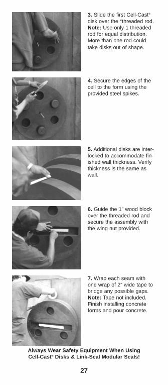
4. Secure the edges of thecell to the form using theprovided steel spikes.
3. Slide the first Cell-Cast®
disk over the *threaded rod.Note: Use only 1 threadedrod for equal distribution.More than one rod couldtake disks out of shape.
6. Guide the 1” wood blockover the threaded rod andsecure the assembly withthe wing nut provided.
7. Wrap each seam withone wrap of 2” wide tape tobridge any possible gaps.Note: Tape not included.Finish installing concreteforms and pour concrete.
5. Additional disks are inter-locked to accommodate fin-ished wall thickness. Verifythickness is the same aswall.
Always Wear Safety Equipment When UsingCell-Cast® Disks & Link-Seal Modular Seals!
28
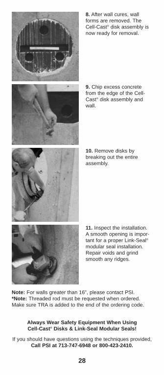
8. After wall cures, wallforms are removed. TheCell-Cast® disk assembly isnow ready for removal.
11. Inspect the installation.A smooth opening is impor-tant for a proper Link-Seal®modular seal installation.Repair voids and grindsmooth any ridges.
If you should have questions using the techniques provided,Call PSI at 713-747-6948 or 800-423-2410.
9. Chip excess concretefrom the edge of the Cell-Cast® disk assembly andwall.
10. Remove disks bybreaking out the entireassembly.
Always Wear Safety Equipment When UsingCell-Cast® Disks & Link-Seal Modular Seals!
Note: For walls greater than 16”, please contact PSI.*Note: Threaded rod must be requested when ordered.Make sure TRA is added to the end of the ordering code.

Warranty and Conditions of SaleThe seller warrants that all goods furnished under this
order will be free from defects in material and workmanshipand will conform to Pipeline Seal & Insulator, Inc. publishedspecifications.
The limit of PSI’s liability for failure of any of our prod-ucts to meet the foregoing warranty, or for breach of anyother warranty, express, implied or statutory, shall be tosupply an equivalent amount of product for any materialsreturned to us within 12 months of shipment and found tobe defective by PSI.
Due to the widely varying conditions under which ourproducts are used or installed, PSI offers no warranty as totheir merchantability, length of service or suitability for anyparticular purpose, express or implied, other than describedabove.
The Purchaser accepts full responsibility for installationof all goods furnished under this order and for any defectsor damage suffered as a result of defective installation ofsuch goods. No instructions, advice, or aid relative to instal-lation given by the Seller to the Purchaser shall be con-strued as a warranty as to the accuracy or utility of suchinstructions, advice, or aid, but only as an accommodationto the Purchaser and an opinion of the Seller.
The foregoing conditions of sale shall not be modifiedor affected in any way whatsoever by reason of Seller’sreceipt or acknowledgement of Buyer’s purchase order orany other related instrument of paper containing additionalor different conditions and, to the extent there may be anyterms or provisions in such a purchase order, etc. whichmay be in conflict with or modification of the foregoing, suchterms and provisions of such purchase order, etc. shall bedeemed to have no force or effect.
©2008, Pipeline Seal & Insulator, Inc.Link-Seal®, Century-Line® and Cell-Cast® are registered trademarks of PSI.

Pipeline Seal & Insulator, Inc.Houston, TX 77021 U.S.A.Telephone: 713-747-6948, Facsimile: 713-747-6029Toll Free: 800-423-2410www.linkseal.com, e-mail: [email protected]
©2007, Pipeline Seal & Insulator, Inc.Link-Seal®, Century-Line® and Cell-Cast® are registered trademarks of PSI.
PSI-PocketGuide 2/08
Quick Tips• Read installation techniques.• Make sure you have the correct
Link-Seal® model and number of links.• Make sure pipe is centered and
supported.• Do not remove links, install exact number
indicated in charts.• Tighten clock-wise pattern, 2 or more
passes at 4 turns per bolt.• Do not use power tools or zip guns on
316 stainless steel bolts.• Do not use grease when installing a belt
of Link-Seal modular seals. If needed,use non-polluting liquid detergent.
Authorized Local Servicing/Stocking Distributor