Embed Size (px)
Citation preview
The Cool One – Features and Benefits
Hot runner molds have been in use for decades. Today, energy costs and material availability have become greater processing considerations and new emphasis is being placed on reducing these costs. As a result, a hot runner molding system that can cut energy requirements, shorten cycles, save material and eliminate secondary operations, such as degating parts, spot facing and regrinding runners, is extremely well-suited for the industry.
What is The Cool One?
The Cool One is a group of standardized, pre-engineered components that can be incorporated into a hot runner mold to suit a specific application. The design of the Cool One places particular emphasis on temperature control throughout the system. Standard Cool One components fall into two categories: Distributor System and Probes.
Distributor System
Plastics are injected into the system through the D-M-E Heated Nozzle Locator. The system consists of bores, gun-drilled into the distributor block. A smaller diameter distributor tube is inserted in each bore and centered with end caps.
Material flowing in the bore, around the central tube, is kept molten by a thermocouple-cartridge heater in the tube. Heating the material “from the inside out” is highly efficient, since it allows heater loads to be considerably less than systems which heat from the outside in. In addition, the outer layer of the melt stream solidifies to form an insulating layer of plastics that further reduces energy requirements and permits mold surface temperatures to be maintained at 100° F. In many cases the flow design has a single primary distributor tube with intersecting probes to direct the flow of material to the gates. A primary and secondary distributor tube layout using a common “H” pattern is also a typical method of providing a balanced flow of material to probes intersecting the secondary tubes. (The cutaway view above is an example of the “H” pattern layout.) A wide variety of intersecting layouts are possible to carry molten material to virtually any number or pattern of cavities.
For even smaller molds, or increased cavitation in larger molds, D-M-E has standardized a group of Micro Cool One components applicable for solid block designs. In this design, smaller distributor tubes and cartridge heaters are used in conjunction with smaller “integral heater” gating probes. The Micro Cool One utilizes round distributor channels and a single level of distribution. System designs incorporate the Solid Block concept (as shown in the illustration above).
Inte
rnal
ly H
eate
d Ho
t Run
ner
Syst
ems
| T
he C
ool O
ne –
Fea
ture
s an
d Be
nefit
sInternally Heated Hot Runner Systems
The Cool One – Features and Benefits
ProbesMolten material flows through the distributor system to intersect with the probes centered in the probe bores. The heated probes keep the material molten and flowing to the gates.
In general, the gate is the most critical point in any hot runner mold. A perfect temperature balance has to be maintained at the gate if the mold is to run effectively. The molder has to find the “compromise” temperature which will fill the cavity, provide good part quality, keep the plastics molten and still shut-off without drooling when the mold opens for part ejection. The gate size and cycle time are also major variables that have to be considered in achieving this proper balance.
With the D-M-E system, cartridge heaters in both the tubes and probes contain integral thermocouples. This allows the heaters to be closely monitored and continuously adjusted by closed-loop temperature controls.
D-M-E Auto-Fixed™ probes are offered in three styles – finless with integral heaters, and finned or finless withreplaceable heaters. The “integral heater” probes are smaller in diameter than the others, making them ideal for smaller molds or closer cavity patterns. The finned style employs a precision-engineered tip configuration that automatically “fixes” the relationship between the probe tip and gate (i.e., centers the probe and limits tip protrusion into the gate). The finless style provides a wider selection of probe lengths (up to 10") for larger molds and deeper cavity configurations. An optional register ring is available for these probes to provide added stability at the probe tip if desired. Probes of different lengths can be used in the same mold to suit the gating requirements and contours of the molded part.
To save the moldmaker valuable machining time, standardized gate inserts are also available for all probes. Made from prehardened AISI S-7 steel, these inserts are pre-machined with the appropriate internal configurations for optimum probe performance.
BenefitsFor The ProcessorSome of the most readily apparent benefits of The Cool One are to the plastics processor. Basically, the system offers more quality parts while reducing labor and material costs.
As proven in actual production, this D-M-E Hot Runner System can:
■ Increase Production … Faster startups, faster cycles and delay-free automatic operation
■ Conserve Energy … “The Cool One” uses up to 75% less energy than conventional hot manifold systems and no regrind operations are necessary
■ Conserve Materials … No sprues or runners and fewer rejects make 50%–80% material savings possible
■ Improve Part Quality … Improved temperature control provides better gate cosmetics, more homogeneous melt
■ Increase Uptime … Contamination can be clearedor cartridge heaters replaced quickly with the mold in the press
For The DesignerStandardized components have established themselves as the best, fastest and least expensive way to design tools. This is especially true with D-M-E pre-engineered hot runner molding components.
■ Maximum Design Flexibility … Improved cosmetics offer wide choice of gate locations; Distributor System configurations are virtually unlimited
■ Production Proven … Predictable performance based on decades of successful applications.
For The Moldmaker■ Shorter Lead Times … Pre-engineered components
allow the moldmaker to go from part print to part approval (and final payment) sooner
■ Availability … Components are available from stock for immediate delivery which means faster mold construction and more uptime
Internally Heated Hot Runner Systems | The Cool O
ne – Features and BenefitsInternally Heated Hot Runner Systems
Internally Heated Hot Runner Systems
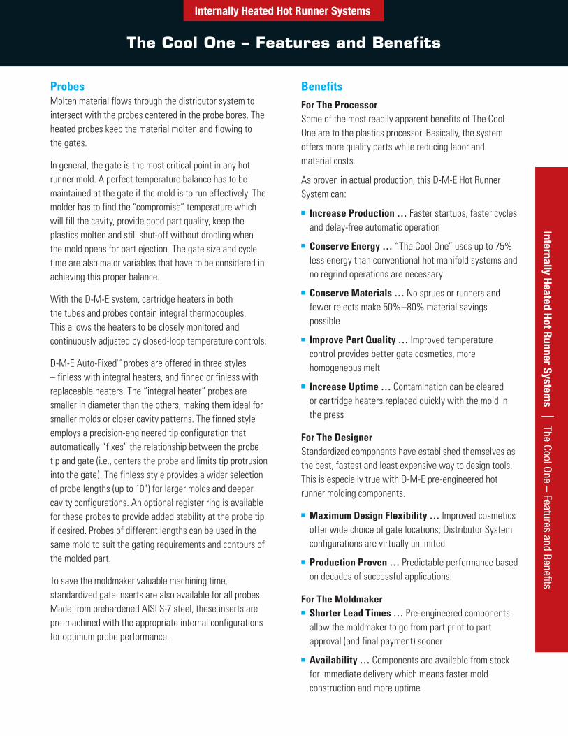
Components for Micro Cool One®
Split Plate/Solid Block Designs
Inte
rnal
ly H
eate
d Ho
t Run
ner
Syst
ems
| C
ompo
nent
s fo
r Mic
ro C
ool O
ne®
Components for Micro Cool One® Split Plate/Solid Block Designs■ Micro components for smaller molds or increased cavitation in larger molds
■ Integral heaters in all probes improve heat transfer throughout system
■ Applicable for split plate or solid block designs
Thermocouple (T/C) Distributor Tube Heaters (240 VAC, T/C Type J, 34" Leads)Distributed wattage heater design for more uniform temperature control. Sealed, flexible teflon covered leads to prevent lead damage and improve moisture resistance.
DIA (AMPS)* ITEM NUMBER OVERALL
LENGTHHEATED LENGTH WATTS
.375 (10 AMP)
HCTC-03-4 5.000 4.000 320HCTC-03-45 5.500 4.500 340HCTC-03-5 6.000 5.000 400HCTC-03-55 6.500 5.500 430HCTC-03-6 7.000 6.000 450HCTC-03-65 7.500 6.500 470HCTC-03-7 8.000 7.000 480
DIA (AMPS)* ITEM NUMBER OVERALL
LENGTHHEATED LENGTH WATTS
.375(10 AMP)
HCTC-03-75 8.500 7.500 515
HCTC-03-8 9.000 8.000 550
HCTC-03-9 10.000 9.000 650HCTC-03 -10 11.000 10.000 710HCTC-03-11 12.000 11.000 720
HCTC-03-12 13.000 12.000 760HCTC-03-13 14.000 13.000 810
*(AMPS) = Amperage requirement for temp. control module.
Distributor TubesMATERIAL: AISI 4140 STEELHARDNESS: 28-35 HRC
End CapMATERIAL: AISI 4140 STEEL
ITEM NUMBER LENGTH
HT-05-03-12 11.82
HT-05-03-16 15.76
ITEM NUMBEREC-11-05
1" NO HEAT AREA
HEATED LENGTH(HEATER)
LENGTH(TUBE)
1.000
.628 O.D.
.375 I.D. 1.125
Locating Ring (for Heated Nozzle Locator)NOTE: In addition to use with Micro Cool One designs, this
locating ring can be used with any Cool One system employing the heated nozzle locator in its design.
ITEM NUMBERHNR0001
Micro Cool One Distributor Tubes, End Caps, Distributor Tube Heaters
See the end of this section for component detail dimensions and design and machining guidelines.
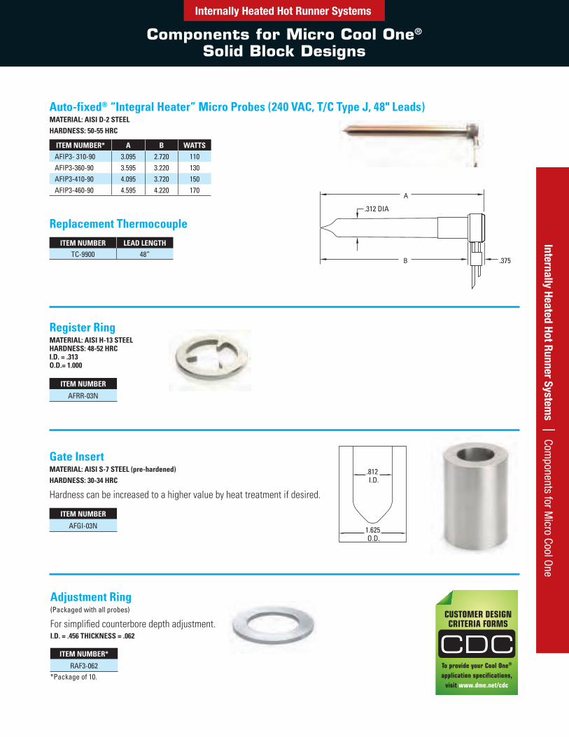
Auto-fixed® “Integral Heater” Micro Probes (240 VAC, T/C Type J, 48" Leads)MATERIAL: AISI D-2 STEELHARDNESS: 50-55 HRC
ITEM NUMBER* A B WATTSAFIP3- 310-90 3.095 2.720 110AFIP3-360-90 3.595 3.220 130AFIP3-410-90 4.095 3.720 150AFIP3-460-90 4.595 4.220 170
ITEM NUMBER LEAD LENGTHTC-9900 48”
ITEM NUMBER
AFRR-03N
ITEM NUMBER
AFGI-03N
ITEM NUMBER*
RAF3-062*Package of 10.
Replacement Thermocouple
Register RingMATERIAL: AISI H-13 STEEL HARDNESS: 48-52 HRC I.D. = .313 O.D.= 1.000
Gate InsertMATERIAL: AISI S-7 STEEL (pre-hardened)HARDNESS: 30-34 HRC
Hardness can be increased to a higher value by heat treatment if desired.
Adjustment Ring(Packaged with all probes)
For simplified counterbore depth adjustment.I.D. = .456 THICKNESS = .062
B
A
.375
.312 DIA
Components for Micro Cool One®
Solid Block Designs
Internally Heated Hot Runner SystemsInternally Heated Hot Runner System
s | Components for M
icro Cool One
To provide your Cool One®
application specifications, visit www.dme.net/cdc
CUSTOMER DESIGNCRITERIA FORMS
CDC
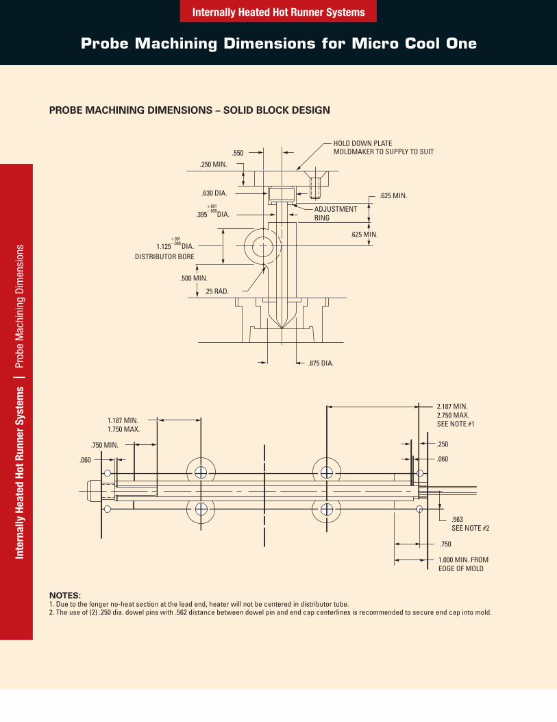
Probe Machining Dimensions for Micro Cool One
Internally Heated Hot Runner SystemsIn
tern
ally
Hea
ted
Hot R
unne
r Sy
stem
s |
Pro
be M
achi
ning
Dim
ensi
ons
.750 MIN.
.060
.250
2.187 MIN.2.750 MAX.SEE NOTE #1
.060
.563SEE NOTE #2
.750
1.000 MIN. FROMEDGE OF MOLD
1.187 MIN.1.750 MAX.
.875 DIA.
.25 RAD.
.500 MIN.
1.125DISTRIBUTOR BORE
.395
.630 DIA.
.250 MIN.
HOLD DOWN PLATEMOLDMAKER TO SUPPLY TO SUIT.550
.625 MIN.
.625 MIN.
ADJUSTMENTRING
DIA.
DIA.
.001
.000
.001
.000
NOTES:1. Due to the longer no-heat section at the lead end, heater will not be centered in distributor tube.2. The use of (2) .250 dia. dowel pins with .562 distance between dowel pin and end cap centerlines is recommended to secure end cap into mold.
PROBE MACHINING DIMENSIONS – SOLID BLOCK DESIGN
Internally Heated Hot Runner Systems | M
icro Cool One D
esign GuidelinesMicro Cool One® Solid Block
Designing and Machining Guidelines and Components
Internally Heated Hot Runner Systems
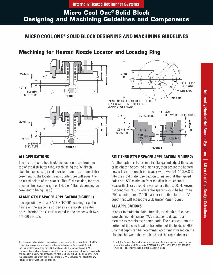
Machining for Heated Nozzle Locator and Locating Ring
ALL APPLICATIONSThe locator’s core tip should be positioned .06 from the top of the distributor tube, establishing the ‘A’ dimen-sion. In most cases, the dimension from the bottom of the core head to the locating ring counterbore will equal the adjusted height of the spacer. (The ‘B’ dimension, for refer-ence, is the heater length of 1.450 or 1.950, depending on core length being used.)
CLAMP STYLE SPACER APPLICATION (FIGURE 1)In conjunction with a D-M-E HNR0001 locating ring, the flange on the spacer is utilized as a clamp style heater nozzle locator. The core is secured to the spacer with two 1/4–20 S.H.C.S.
BOLT THRU STYLE SPACER APPLICATION (FIGURE 2)Another option is to remove the flange and adjust the spac-er height to the desired dimension, then secure the heated nozzle locator through the spacer with two 1/4–20 S.H.C.S. into the mold plate. Use caution to insure that the tapped holes are .500 minimum from the distributor channel. Spacer thickness should never be less than .250. However, if a condition results where the spacer would be less than .250, counterbore a 2.000 diameter into the plate to a ‘V’ depth that will accept the .250 spacer. (See Figure 3)
ALL APPLICATIONSIn order to maintain plate strength, the depth of the lead wire channel, dimension ‘W’, must be no deeper than required to contain the heater leads. The distance from the bottom of the core head to the bottom of the leads is .800. Channel depth can be determined accordingly, based on the distance between the core head and the top of the mold.
.156 REF..06 FROM
DIST. TUBE FIGURE 1
.500 MIN.
.156 REF.
.06 FROMDIST. TUBE FIGURE 2
.500 MIN.
B A
BA
1/4–20 TAP (2) HOLES FOR BOLT THRUSTYLE SPACER. OMIT HOLES FOR CLAMP STYLE SPACER
.219 .125 RAD MIN.
FIGURE 3
WV
5/16–18 TAP(2) HOLES
1.656 RAD.
.718 RAD.
.375SHOWN OUT OF POSITION
.06 × 45°CHAMFER
.06 RAD.
.5000
.5005DIA.
1.060 DIA.
.15615°
4.000DIA.
45°
2.000DIA.
MICRO COOL ONE® SOLID BLOCK DESIGNING AND MACHINING GUIDELINES
The design guidelines in this document are based upon results obtained using D-M-E’s production equipment and are provided as a design aid for use with D-M-E Hot Runner Systems. They are ONLY applicable to the current line of D-M-E components detailed in this document. Due to the wide variety of plastics materials and possible molding applications available, and since D-M-E has no control over the circumstances of any molding operation, D-M-E assumes no liability for any results obtained with this information.
D-M-E Hot Runner System Components are manufactured and sold under one or more of the following U.S. patents, 3,767,340; 3,010,155; 3,023,458; 3,231,938 AND 3,758,248. FOREIGN PATENTS ISSUED AND PENDING.
Internally Heated Hot Runner Systems
The Cool One – Heated Nozzle Locators, Assemblies and Replacement Parts
Inte
rnal
ly H
eate
d Ho
t Run
ner
Syst
ems
| T
he C
ool O
ne –
Hea
ted
Noz
zle
Loca
tors
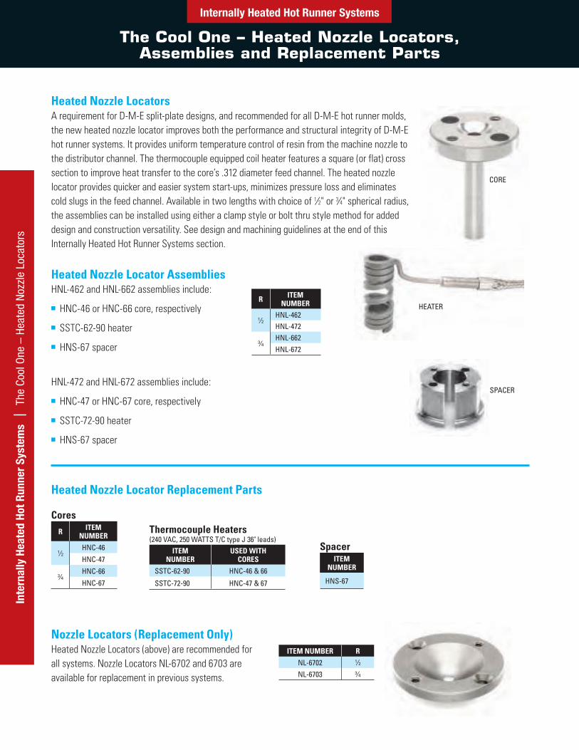
Heated Nozzle LocatorsA requirement for D-M-E split-plate designs, and recommended for all D-M-E hot runner molds, the new heated nozzle locator improves both the performance and structural integrity of D-M-E hot runner systems. It provides uniform temperature control of resin from the machine nozzle to the distributor channel. The thermocouple equipped coil heater features a square (or flat) cross section to improve heat transfer to the core’s .312 diameter feed channel. The heated nozzle locator provides quicker and easier system start-ups, minimizes pressure loss and eliminates cold slugs in the feed channel. Available in two lengths with choice of 1⁄2" or 3⁄4" spherical radius, the assemblies can be installed using either a clamp style or bolt thru style method for added design and construction versatility. See design and machining guidelines at the end of this Internally Heated Hot Runner Systems section.
R ITEM NUMBER
1⁄2HNL-462HNL-472
3⁄4HNL-662HNL-672
CoresR ITEM
NUMBER
1⁄2HNC-46
HNC-47
3⁄4HNC-66
HNC-67
Thermocouple Heaters(240 VAC, 250 WATTS T/C type J 36" leads)
ITEM NUMBER
USED WITH CORES
SSTC-62-90 HNC-46 & 66
SSTC-72-90 HNC-47 & 67
SpacerITEM
NUMBER
HNS-67
ITEM NUMBER R
NL-6702 1⁄2
NL-6703 3⁄4
Heated Nozzle Locator AssembliesHNL-462 and HNL-662 assemblies include:
■ HNC-46 or HNC-66 core, respectively
■ SSTC-62-90 heater
■ HNS-67 spacer
HNL-472 and HNL-672 assemblies include:
■ HNC-47 or HNC-67 core, respectively
■ SSTC-72-90 heater
■ HNS-67 spacer
Heated Nozzle Locator Replacement Parts
Nozzle Locators (Replacement Only)Heated Nozzle Locators (above) are recommended for all systems. Nozzle Locators NL-6702 and 6703 are available for replacement in previous systems.
CORE
SPACER
HEATER
Internally Heated Hot Runner Systems
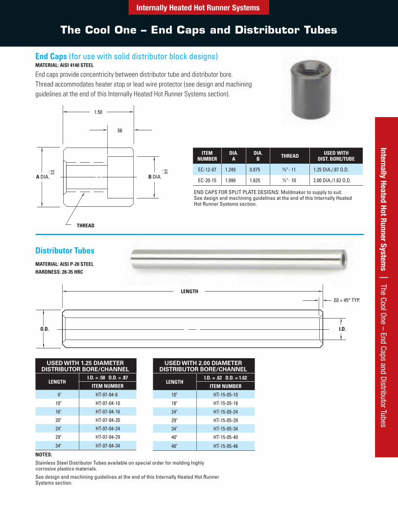
The Cool One – End Caps and Distributor Tubes
Internally Heated Hot Runner Systems | The Cool O
ne – End Caps and Distributor Tubes
USED WITH 1.25 DIAMETER DISTRIBUTOR BORE/CHANNEL
LENGTHI.D. = .50 O.D. = .87
ITEM NUMBER
6" HT-07-04-6
10" HT-07-04-10
16" HT-07-04-16
20" HT-07-04-20
24" HT-07-04-24
29" HT-07-04-29
34" HT-07-04-34
Distributor TubesMATERIAL: AISI P-20 STEELHARDNESS: 28-35 HRC
USED WITH 2.00 DIAMETER DISTRIBUTOR BORE/CHANNEL
LENGTHI.D. = .62 O.D. = 1.62
ITEM NUMBER
10" HT-15-05-10
18" HT-15-05-18
24" HT-15-05-24
29" HT-15-05-29
34" HT-15-05-34
40" HT-15-05-40
46" HT-15-05-46
NOTES:
Stainless Steel Distributor Tubes available on special order for molding highly corrosive plastics materials.
See design and machining guidelines at the end of this Internally Heated Hot Runner Systems section.
LENGTH
O.D. I.D.
.03 × 45° TYP.
End Caps (for use with solid distributor block designs)MATERIAL: AISI 4140 STEEL
End caps provide concentricity between distributor tube and distributor bore. Thread accommodates heater stop or lead wire protector (see design and machining guidelines at the end of this Internally Heated Hot Runner Systems section).
ITEM NUMBER
DIA. A
DIA. B THREAD USED WITH
DIST. BORE/TUBE
EC-12-07 1.249 0.875 5⁄8"- 11 1.25 DIA./.87 O.D.
EC-20-15 1.999 1.625 3⁄4"- 10 2.00 DIA./1.62 O.D.
END CAPS FOR SPLIT PLATE DESIGNS: Moldmaker to supply to suit. See design and machining guidelines at the end of this Internally Heated Hot Runner Systems section.
.
Internally Heated Hot Runner Systems
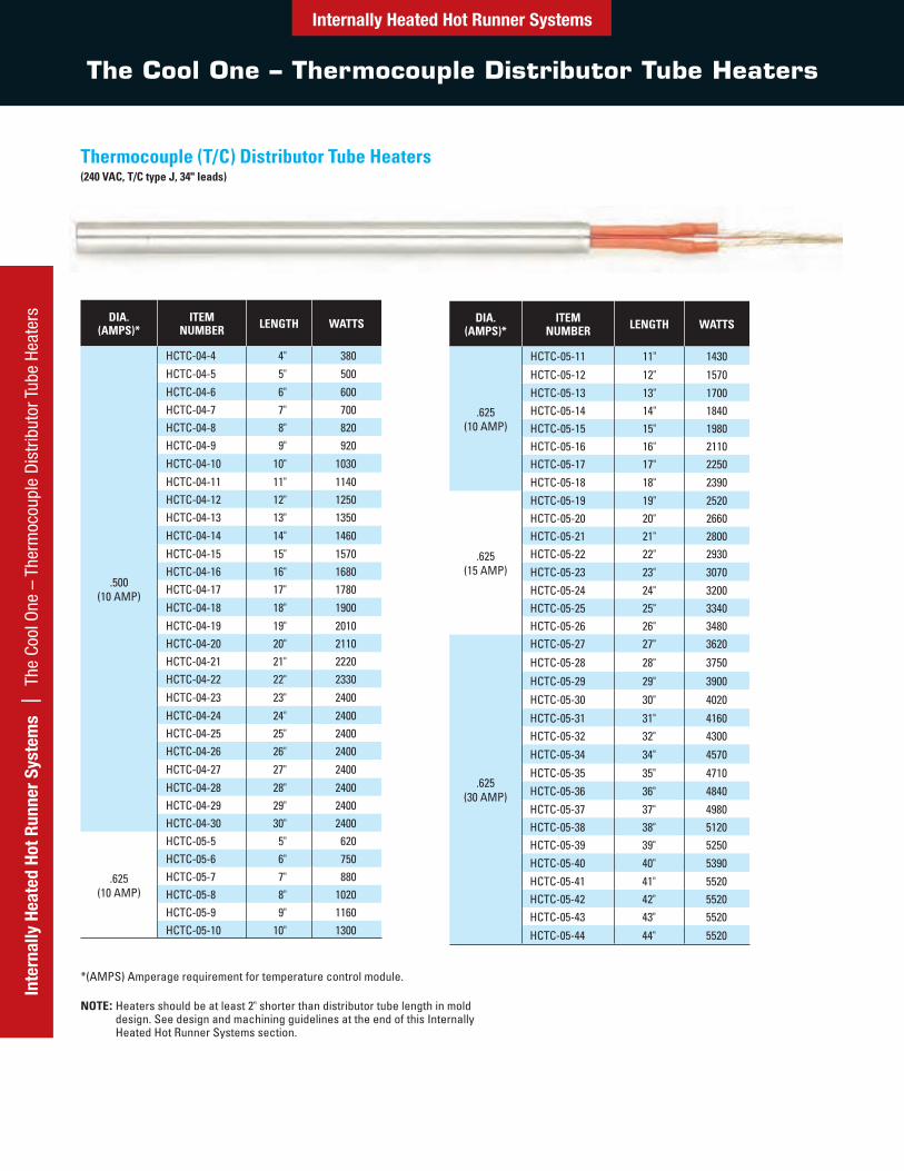
The Cool One – Thermocouple Distributor Tube Heaters
Inte
rnal
ly H
eate
d Ho
t Run
ner
Syst
ems
| T
he C
ool O
ne –
The
rmoc
oupl
e D
istr
ibut
or T
ube
Heat
ers DIA.
(AMPS)*ITEM
NUMBER LENGTH WATTS
.500 (10 AMP)
HCTC-04-4 4" 380HCTC-04-5 5" 500HCTC-04-6 6" 600HCTC-04-7 7" 700HCTC-04-8 8" 820HCTC-04-9 9" 920HCTC-04-10 10" 1030HCTC-04-11 11" 1140HCTC-04-12 12" 1250HCTC-04-13 13" 1350HCTC-04-14 14" 1460HCTC-04-15 15" 1570HCTC-04-16 16" 1680HCTC-04-17 17" 1780HCTC-04-18 18" 1900HCTC-04-19 19" 2010HCTC-04-20 20" 2110HCTC-04-21 21" 2220HCTC-04-22 22" 2330HCTC-04-23 23" 2400HCTC-04-24 24" 2400HCTC-04-25 25" 2400HCTC-04-26 26" 2400HCTC-04-27 27" 2400HCTC-04-28 28" 2400HCTC-04-29 29" 2400HCTC-04-30 30" 2400
.625 (10 AMP)
HCTC-05-5 5" 620HCTC-05-6 6" 750HCTC-05-7 7" 880HCTC-05-8 8" 1020HCTC-05-9 9" 1160HCTC-05-10 10" 1300
DIA. (AMPS)*
ITEM NUMBER LENGTH WATTS
.625 (10 AMP)
HCTC-05-11 11" 1430
HCTC-05-12 12" 1570HCTC-05-13 13" 1700HCTC-05-14 14" 1840HCTC-05-15 15" 1980HCTC-05-16 16" 2110HCTC-05-17 17" 2250HCTC-05-18 18" 2390
.625 (15 AMP)
HCTC-05-19 19" 2520HCTC-05-20 20" 2660HCTC-05-21 21" 2800HCTC-05-22 22" 2930HCTC-05-23 23" 3070HCTC-05-24 24" 3200HCTC-05-25 25" 3340HCTC-05-26 26" 3480
.625(30 AMP)
HCTC-05-27 27" 3620
HCTC-05-28 28" 3750
HCTC-05-29 29" 3900
HCTC-05-30 30" 4020
HCTC-05-31 31" 4160HCTC-05-32 32" 4300
HCTC-05-34 34" 4570
HCTC-05-35 35" 4710HCTC-05-36 36" 4840HCTC-05-37 37" 4980HCTC-05-38 38" 5120HCTC-05-39 39" 5250HCTC-05-40 40" 5390HCTC-05-41 41" 5520HCTC-05-42 42" 5520HCTC-05-43 43" 5520
HCTC-05-44 44" 5520
Thermocouple (T/C) Distributor Tube Heaters(240 VAC, T/C type J, 34" leads)
*(AMPS) Amperage requirement for temperature control module.
NOTE: Heaters should be at least 2" shorter than distributor tube length in mold design. See design and machining guidelines at the end of this Internally Heated Hot Runner Systems section.
Internally Heated Hot Runner Systems
The Cool One – Components
Internally Heated Hot Runner Systems | The Cool O
ne – Components
C DIA.
A DIA.
B DIA.
15° TYP.
.125 120° TYP.
.06 TYP.
+ .001– .000
+ .000– .001
+ .000– .001
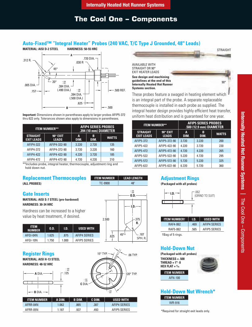
Auto-Fixed™ “Integral Heater” Probes (240 VAC, T/C Type J Grounded, 48" Leads)MATERIAL: AISI D-2 STEEL HARDNESS: 50-55 HRC
Important: Dimensions shown in parentheses apply to larger probes AFIP5-372 thru 622 only. Tolerances shown also apply to dimensions in parentheses.
ITEM NUMBER** AFIP4 SERIES PROBES .394 (10 mm) DIAMETER
STRAIGHT EXIT LEADS
90° EXIT LEADS
A DIM.
B DIM. WATTS
AFIP4-322 AFIP4-322-90 3.220 2.720 135AFIP4-372 AFIP4-372-90 3.720 3.220 160AFIP4-422 AFIP4-422-90 4.220 3.720 185AFIP4-472 AFIP4-472-90 4.720 4.220 210
**lncludes probe, integral heater, thermocouple, adjustment ring and hold down nut.
ITEM NUMBER** AFIP5 SERIES PROBES .500 (12.9 mm) DIAMETER
STRAIGHT EXIT LEADS
90° EXIT LEADS
A DIM.
B DIM. WATTS
AFIP5-372 AFIP5-372-90 3.720 3.220 200AFIP5-422 AFIP5-422-90 4.220 3.720 230AFIP5-472 AFIP5-472-90 4.720 4.220 265AFIP5-522 AFIP5-522-90 5.220 4.720 295AFIP5-572 AFIP5-572-90 5.720 5.220 325AFIP5-622 AFIP5-622-90 6.220 5.720 360
Replacement Thermocouples(ALL PROBES)
ITEM NUMBER LEAD LENGTHTC-9900 48"
Register RingsMATERIAL: AISI H-13 STEELHARDNESS: 48-52 HRC
ITEM NUMBER A DIM. B DIM. C DIM. USED WITHAFRR-04N 1.062 .865 .387 AFIP4 SERIESAFRR-05N 1.187 .937 .493 AFIP5 SERIES
Adjustment Rings(Packaged with all probes)
Hold-Down Nut(Packaged with all probes)THICKNESS = .500 THREAD = 1"- 8 HEX FLAT = 9⁄16
ITEM NUMBER† I.D. USED WITHRAF4-062 .469 AFIP4 SERIESRAF5-062 .565 AFIP5 SERIES
†Bag of 5 rings.
*Required for straight exit leads only.
Gate InsertsMATERIAL: AISI S-7 STEEL (pre-hardened)HARDNESS: 30-34 HRC
Hardness can be increased to a higher value by heat treatment, if desired.
ITEM NUMBER O.D. I.D. USED WITH
AFGI-04N 1.625 .875 AFIP4 SERIESAFGI-10N 1.750 1.000 AFIP5 SERIES
ITEM NUMBER
AFN-100
ITEM NUMBER
WR-916
I.D. .062(GRIND TO SUIT)
90°
STRAIGHT
Hold-Down Nut Wrench*
2.500 .375R.
.187SPH. R..625 45°
O.D.
I.D.
+ .005– .000
AVAILABLE WITH STRAIGHT OR 90° EXIT HEATER LEADSSee design and machining guidelines at the end of this Internally Heated Hot Runner Systems section.
These probes feature a swaged in heating element which is an integral part of the probe. A separate replaceable thermocouple is installed in each probe as supplied. The integral heater design provides highly efficient heat transfer, uniform heat distribution and is guaranteed for one year.
Internally Heated Hot Runner Systems
The Cool One – Probes and Probe Heaters
Inte
rnal
ly H
eate
d Ho
t Run
ner
Syst
ems
| T
he C
ool O
ne –
Pro
bes
and
Prob
e He
ater
s
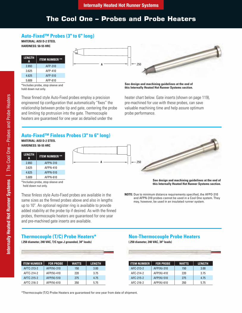
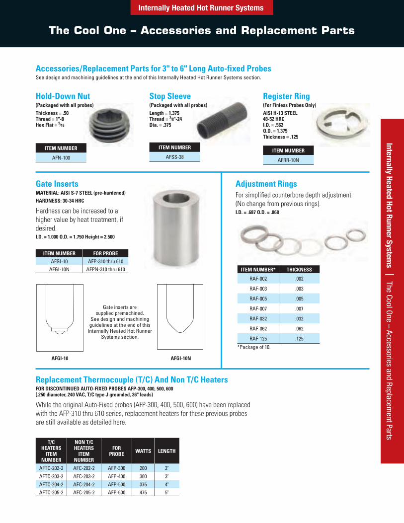
Auto-Fixed™ Probes (3" to 6" long)MATERIAL: AISI D-2 STEELHARDNESS: 50-55 HRC
LENGTH A ITEM NUMBER **
2.893 AFP-3103.625 AFP-4104.625 AFP-5105.609 AFP-610
*Includes probe, stop sleeve and hold down nut only.
These finned style Auto-Fixed probes employ a precision engineered tip configuration that automatically “fixes” the relationship between probe tip and gate, centering the probe and limiting tip protrusion into the gate. Thermocouple heaters are guaranteed for one year as detailed under the
heater chart below. Gate inserts (shown on page 119), pre-machined for use with these probes, can save valuable machining time and help assure optimum probe performance.
Auto-Fixed™ Finless Probes (3" to 6" long)MATERIAL: AISI D-2 STEELHARDNESS: 50-55 HRC
See design and machining guidelines at the end of this Internally Heated Hot Runner Systems section.
LENGTH A ITEM NUMBER **
2.893 AFPN-3103.625 AFPN-4104.625 AFPN-5105.609 AFPN-610
*Includes probe, stop sleeve and hold down nut only.
These finless style Auto-Fixed probes are available in the same sizes as the finned probes above and also in lengths up to 10". An optional register ring is available to provide added stability at the probe tip if desired. As with the finned probes, thermocouple heaters are guaranteed for one year and pre-machined gate inserts are available.
NOTE: Due to minimum distance requirements specified, the AFPO-310 and AFPN-310 probes cannot be used in a Cool One system. They may, however, be used in an insulated runner system.
ITEM NUMBER FOR PROBE WATTS LENGTHAFTC-213-2 AFP(N)-310 150 3.00AFTC-214-2 AFP(N)-410 220 3.75AFTC-215-2 AFP(N)-510 275 4.75AFTC-216-2 AFP(N)-610 350 5.75
ITEM NUMBER FOR PROBE WATTS LENGTHAFC-213-2 AFP(N)-310 150 3.00AFC-214-2 AFP(N)-410 220 3.75AFC-215-2 AFP(N)-510 275 4.75AFC-216-2 AFP(N)-610 350 5.75
*Thermocouple (T/C) Probe Heaters are guaranteed for one year from date of shipment.
Thermocouple (T/C) Probe Heaters*(.250 diameter, 240 VAC, T/C type J grounded, 34" leads)
See design and machining guidelines at the end of this Internally Heated Hot Runner Systems section.
Non-Thermocouple Probe Heaters(.250 diameter, 240 VAC, 34" leads)
Internally Heated Hot Runner Systems | The Cool O
ne – Accessories and Replacement Parts
The Cool One – Accessories and Replacement Parts
Internally Heated Hot Runner Systems
Hold-Down Nut(Packaged with all probes)Thickness = .50 Thread = 1"-8 Hex Flat = 9⁄16
ITEM NUMBER
AFN-100
Stop Sleeve(Packaged with all probes)Length = 1.375 Thread = 3⁄8"-24Dia. = .375
ITEM NUMBER
AFSS-38
Register Ring(For Finless Probes Only)AISI H-13 STEEL 48-52 HRC I.D. = .562 O.D. = 1.375 Thickness = .125
ITEM NUMBER
AFRR-10N
Accessories/Replacement Parts for 3" to 6" Long Auto-fixed ProbesSee design and machining guidelines at the end of this Internally Heated Hot Runner Systems section.
Gate InsertsMATERIAL: AISI S-7 STEEL (pre-hardened)HARDNESS: 30-34 HRC
Hardness can be increased to a higher value by heat treatment, if desired.I.D. = 1.000 O.D. = 1.750 Height = 2.500
ITEM NUMBER FOR PROBEAFGI-10 AFP-310 thru 610
AFGI-10N AFPN-310 thru 610
Adjustment RingsFor simplified counterbore depth adjustment (No change from previous rings).I.D. = .687 O.D. = .868
Gate inserts are supplied premachined.
See design and machining guidelines at the end of this
Internally Heated Hot Runner Systems section.
AFGI-10 AFGI-10N
ITEM NUMBER* THICKNESS
RAF-002 .002
RAF-003 .003
RAF-005 .005
RAF-007 .007
RAF-032 .032
RAF-062 .062
RAF-125 .125
*Package of 10.
Replacement Thermocouple (T/C) And Non T/C HeatersFOR DISCONTINUED AUTO-FIXED PROBES AFP-300, 400, 500, 600 (.250 diameter, 240 VAC, T/C type J grounded, 36" leads)
While the original Auto-Fixed probes (AFP-300, 400, 500, 600) have been replaced with the AFP-310 thru 610 series, replacement heaters for these previous probes are still available as detailed here.
T/C HEATERS
ITEM NUMBER
NON T/C HEATERS
ITEM NUMBER
FOR PROBE WATTS LENGTH
AFTC-202-2 AFC-202-2 AFP-300 200 2"
AFTC-203-2 AFC-203-2 AFP-400 300 3"AFTC-204-2 AFC-204-2 AFP-500 375 4"AFTC-205-2 AFC-205-2 AFP-600 475 5"
Inte
rnal
ly H
eate
d Ho
t Run
ner
Syst
ems
| T
he C
ool O
ne –
Acc
esso
ries
and
Repl
acem
ent P
arts
The Cool One – Accessories and Replacement Parts
Internally Heated Hot Runner Systems
Hold-Down Nut(Packaged with all probes)Thickness = .50 Thread = 1¼"-12 Hex Flat = 5⁄8
ITEM NUMBER
AFN-125
Stop Sleeve(Packaged with all probes)Length = 1.375 Thread = 1⁄2"-20Dia. = .500
ITEM NUMBER
AFSS-12
Register RingAISI H-13 STEEL 48-52 HRC I.D. = .693 O.D. = 1.500
ITEM NUMBER
AFRR-20N
Auto-Fixed™ Finless Probes (7" to 10" long)MATERIAL: AISI D-2 STEEL HARDNESS: 50-55 HRC
LENGTH A
ITEM NUMBER**
7.000 AFPN-7208.000 AFPN-8209.000 AFPN-920
10.000 AFPN-1020**Includes probe, stop sleeve and hold down nut only.
Gate InsertMATERIAL: AISI S-7 STEEL (pre-hardened)HARDNESS: 30-34 HRC
Hardness can be increased to a higher value by heat treatment, if desired.I.D. = 1.125 O.D. = 2000 Height = 2.500
ITEM NUMBERAFGI-20N
Thermocouple (T/C) Probe Heaters†
(.375 diameter, 240 VAC, T/C type J grounded, 46" leads)
ITEM NUMBER FOR PROBE WATTS LENGTHAFTC-327-2 AFPN-720 645 7.15AFTC-328-2 AFPN-820 760 8.15AFTC-329-2 AFPN-920 870 9.15AFTC-3210-2 AFPN-1020 980 10.15
† Thermocouple (T/C) Probe Heaters are guaranteed for one year from date of shipment. Adjustment Rings
Moldmaker to supply to suit (.990 O.D., .820 I.D.)
See design and machining guidelines at the end of this Internally Heated Hot Runner Systems section.
These longer probes are ideal for larger molds or gating into deeper cavity configurations. The optional register ring shown below may be used to provide added stability at the probe tip if desired. Thermocouple heaters are guaranteed for one year as detailed under the heater chart below.
A .375
Internally Heated Hot Runner Systems | Split Plate D
esign
Split Plate Design
Internally Heated Hot Runner Systems
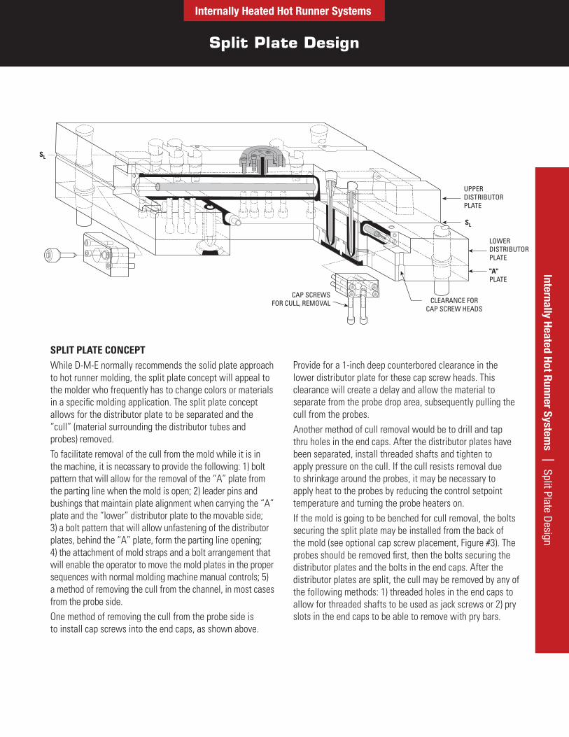
SPLIT PLATE CONCEPTWhile D-M-E normally recommends the solid plate approach to hot runner molding, the split plate concept will appeal to the molder who frequently has to change colors or materials in a specific molding application. The split plate concept allows for the distributor plate to be separated and the “cull” (material surrounding the distributor tubes and probes) removed.To facilitate removal of the cull from the mold while it is in the machine, it is necessary to provide the following: 1) bolt pattern that will allow for the removal of the “A” plate from the parting line when the mold is open; 2) leader pins and bushings that maintain plate alignment when carrying the “A” plate and the “lower” distributor plate to the movable side; 3) a bolt pattern that will allow unfastening of the distributorplates, behind the “A” plate, form the parting line opening; 4) the attachment of mold straps and a bolt arrangement thatwill enable the operator to move the mold plates in the proper sequences with normal molding machine manual controls; 5) a method of removing the cull from the channel, in most cases from the probe side.One method of removing the cull from the probe side is to install cap screws into the end caps, as shown above.
Provide for a 1-inch deep counterbored clearance in the lower distributor plate for these cap screw heads. This clearance will create a delay and allow the material to separate from the probe drop area, subsequently pulling the cull from the probes.Another method of cull removal would be to drill and tap thru holes in the end caps. After the distributor plates have been separated, install threaded shafts and tighten to apply pressure on the cull. If the cull resists removal due to shrinkage around the probes, it may be necessary to apply heat to the probes by reducing the control setpoint temperature and turning the probe heaters on.If the mold is going to be benched for cull removal, the bolts securing the split plate may be installed from the back of the mold (see optional cap screw placement, Figure #3). The probes should be removed first, then the bolts securing the distributor plates and the bolts in the end caps. After the distributor plates are split, the cull may be removed by any of the following methods: 1) threaded holes in the end caps to allow for threaded shafts to be used as jack screws or 2) pry slots in the end caps to be able to remove with pry bars.
CLEARANCE FORCAP SCREW HEADS
CAP SCREWSFOR CULL, REMOVAL
LOWERDISTRIBUTORPLATE
"A"PLATE
SL
SL
UPPERDISTRIBUTORPLATE

Split Plate Designs and Machining Guidelines – Trapezoids
Inte
rnal
ly H
eate
d Ho
t Run
ner
Syst
ems
| S
plit
Plat
e D
esig
ns a
nd M
achi
ning
– T
rape
zoid
sInternally Heated Hot Runner Systems
Two Level Trapezoid
Single Level Trapezoid
B
B
S L SL
D-M-E LOCATING RING 6521
BOLT THRUSTYLE SPACER
CLAMP STYLE SPACER D-M-E LOCATING RING 6524 (MODIFIED)
PRIMARYDIST. CHANNEL
IMPORTANT - END THIS POSITION OF INSULATION CHANNEL .50 MIN. FROM END CAP
WATER LINES AY BE WITHIN .31 OF PROBEOR DISTRIBUTOR BORE
BORE LOCATOR A
A
SECONDARYDIST. CHANNEL
E DIM.SLSL
NOTE: The SL symbol indicates the split line for split plate designs.
FIGURE 2
Dimensions and callouts on each side view (Figures 1, 2 and 3) can be applied to all three side views.
FIGURE 1
Internally Heated Hot Runner Systems
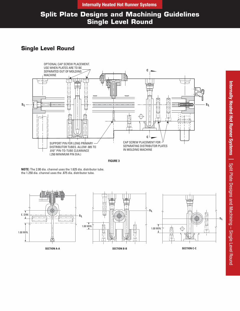
Split Plate Designs and Machining Guidelines Single Level Round
Internally Heated Hot Runner Systems | Split Plate D
esigns and Machining – Single Level Round
C
C
CAP SCREW PLACEMENT FORSEPARATING DISTRIBUTOR PLATESIN MOLDING MACHINE
SUPPORT PIN FOR LONG PRIMARYDISTRIBUTOR TUBES. ALLOW .005 TO.010” PIN-TO-TUBE CLEARANCE(.250 MINIMUM PIN DIA.)
OPTIONAL CAP SCREW PLACEMENT.USE WHEN PLATES ARE TO BESEPARATED OUT OF MOLDING MACHINE
SLSL
E. DIM.
1.00 MIN.
SECTION A-A SECTION B-B SECTION C-C
1.00 MIN.1.00 MIN.
SL
S L
S L
NOTE: The 2.00 dia. channel uses the 1.625 dia. distributor tube. the 1.250 dia. channel uses the .875 dia. distributor tube.
FIGURE 3
Single Level Round
Internally Heated Hot Runner Systems
Split Plate Design and Machining Guidelines
Inte
rnal
ly H
eate
d Ho
t Run
ner
Syst
ems
| S
plit
Plat
e D
esig
n an
d M
achi
ning
Gui
delin
es
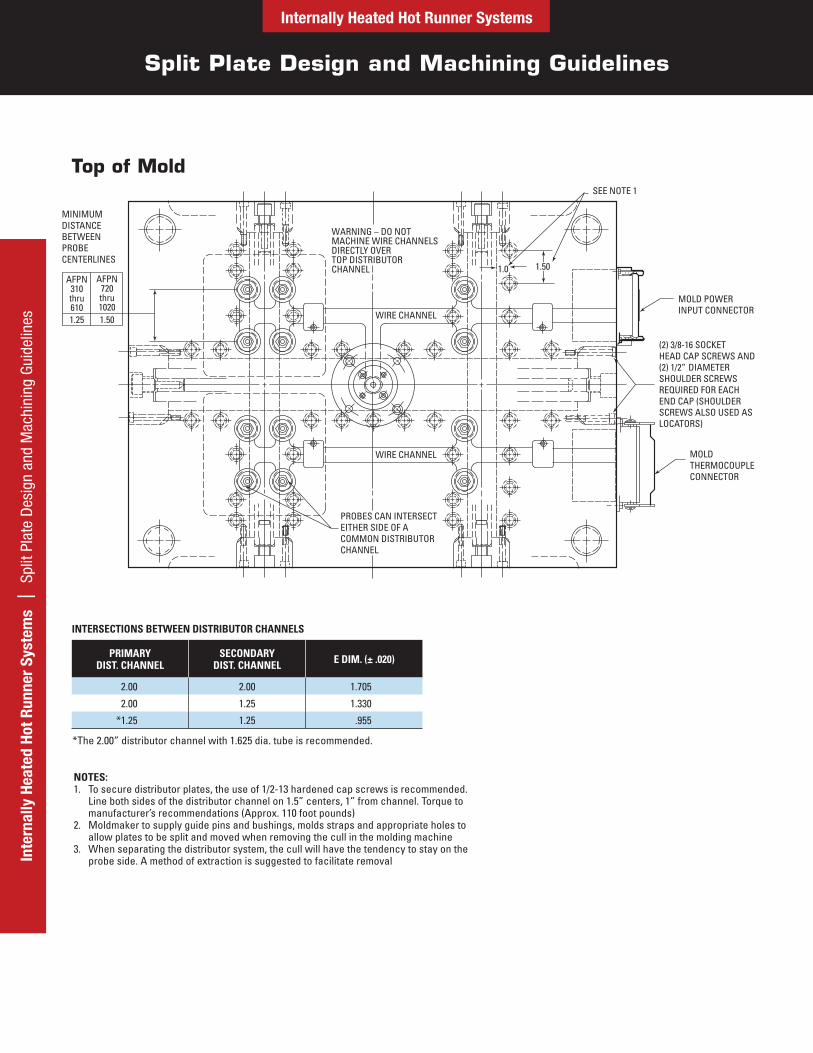
Top of Mold
MINIMUMDISTANCEBETWEENPROBECENTERLINES
WARNING – DO NOTMACHINE WIRE CHANNELSDIRECTLY OVERTOP DISTRIBUTORCHANNEL
WIRE CHANNEL
WIRE CHANNEL
PROBES CAN INTERSECTEITHER SIDE OF ACOMMON DISTRIBUTORCHANNEL
1.0 1.50
SEE NOTE 1
MOLD POWERINPUT CONNECTOR
(2) 1/2”
(2) 3/8-16 SOCKETHEAD CAP SCREWS AND
DIAMETERSHOULDER SCREWSREQUIRED FOR EACHEND CAP (SHOULDER SCREWS ALSO USED ASLOCATORS)
MOLDTHERMOCOUPLECONNECTOR
AFPN310thru610
AFPN720thru1020
1.25 1.50
PRIMARY DIST. CHANNEL
SECONDARY DIST. CHANNEL E DIM. (± .020)
2.00 2.00 1.705
2.00 1.25 1.330
*1.25 1.25 .955
INTERSECTIONS BETWEEN DISTRIBUTOR CHANNELS
*The 2.00” distributor channel with 1.625 dia. tube is recommended.
NOTES:To secure distributor plates, the use of 1/2-13 hardened cap screws is recommended. Line both sides of the distributor channel on 1.5” centers, 1” from channel. Torque to manufacturer’s recommendations (Approx. 110 foot pounds)Moldmaker to supply guide pins and bushings, molds straps and appropriate holes to allow plates to be split and moved when removing the cull in the molding machineWhen separating the distributor system, the cull will have the tendency to stay on the probe side. A method of extraction is suggested to facilitate removal
1.
2.
3.
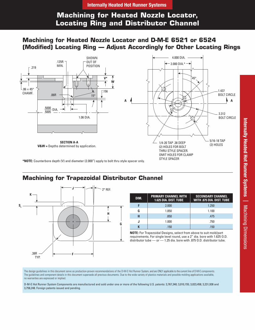
Machining for Heated Nozzle Locator, Locating Ring and Distributor Channel
Internally Heated Hot Runner SystemsInternally Heated Hot Runner System
s | Machining D
imensions
.219
.125RMIN.
SHOWNOUT OFPOSITION
V*
.15615°
1.06 DIA.
.5000
.5005DIA.
.06 × 45°CHAMF. .06R
1.437BOLT CIRCLE
3.312BOLT CIRCLE
5/16-18 TAP(2) HOLES1/4-20 TAP .38 DEEP
(2) HOLES FOR BOLTTHRU STYLE SPACER.OMIT HOLES FOR CLAMPSTYLE SPACER
W
4.000 DIA.
2.000 DIA.*
45°
A A
Machining for Heated Nozzle Locator and D-M-E 6521 or 6524 (Modified) Locating Ring — Adjust Accordingly for Other Locating Rings
SECTION A-AV&W = Depths determined by application.
*NOTE: Counterbore depth (V) and diameter (2.000”) apply to bolt thru style spacer only.
Machining for Trapezoidal Distributor Channel
K
SL
.38RTYP.
2° REF.J
G
F
H
DIM. PRIMARY CHANNEL WITH 1.625 DIA. DIST. TUBE
SECONDARY CHANNEL WITH .875 DIA. DIST. TUBE
F 2.000 1.250
G 1.850 1.100
H .850 .475
J 1.000 .750
K .150 .150
NOTE: For Trapezoidal Designs, select from above to suit mold/part requirements. For single level round, use a 2” dia. bore with 1.625 O.D. distributor tube — or — 1.25 dia. bore with .875 O.D. distributor tube.
The design guidelines in this document serve as production-proven recommendations of the D-M-E Hot Runner System, and are ONLY applicable to the current line of D-M-E components. The guidelines and component details in this document supersede all previous documents. Due to the wide variety of plastics materials and possible molding applications available, no warranties are expressed or implied.
D-M-E Hot Runner System Components are manufactured and sold under one or more of the following U.S. patents: 3,767,340; 3,010,155; 3,023,458; 3,231,938 and 3,758,248. Foreign patents issued and pending.
90° INCL. MAX.
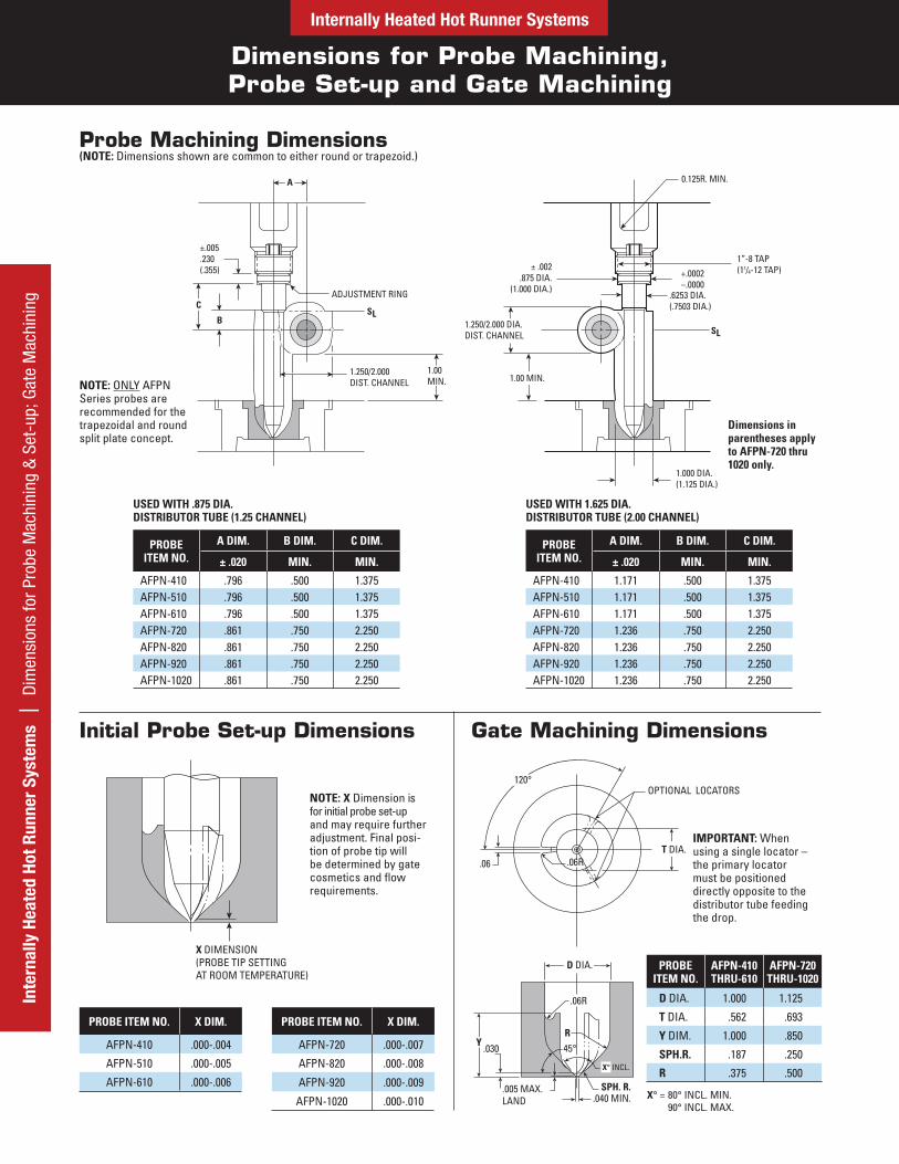
Dimensions for Probe Machining, Probe Set-up and Gate Machining
Internally Heated Hot Runner SystemsIn
tern
ally
Hea
ted
Hot R
unne
r Sy
stem
s |
Dim
ensi
ons
for P
robe
Mac
hini
ng &
Set
-up;
Gat
e M
achi
ning
±.005.230(.355)
ADJUSTMENT RING
SL
1.250/2.000DIST. CHANNEL
B
C
A
1.00MIN.
0.125R. MIN.
1”-8 TAP(11/4-12 TAP)+.0002
–.0000.6253 DIA.(.7503 DIA.)
SL
± .002.875 DIA.
(1.000 DIA.)
1.000 DIA.(1.125 DIA.)
1.250/2.000 DIA.DIST. CHANNEL
1.00 MIN.
Probe Machining Dimensions(NOTE: Dimensions shown are common to either round or trapezoid.)
PROBE ITEM NO.
A DIM. B DIM. C DIM.
± .020 MIN. MIN.
AFPN-410 .796 .500 1.375AFPN-510 .796 .500 1.375AFPN-610 .796 .500 1.375AFPN-720 .861 .750 2.250AFPN-820 .861 .750 2.250AFPN-920 .861 .750 2.250AFPN-1020 .861 .750 2.250
PROBE ITEM NO.
A DIM. B DIM. C DIM.
± .020 MIN. MIN.
AFPN-410 1.171 .500 1.375AFPN-510 1.171 .500 1.375AFPN-610 1.171 .500 1.375AFPN-720 1.236 .750 2.250AFPN-820 1.236 .750 2.250AFPN-920 1.236 .750 2.250AFPN-1020 1.236 .750 2.250
NOTE: ONLY AFPN Series probes are recommended for the trapezoidal and round split plate concept.
Dimensions in parentheses apply to AFPN-720 thru 1020 only.
Initial Probe Set-up Dimensions Gate Machining Dimensions
PROBE ITEM NO. X DIM.
AFPN-410 .000-.004
AFPN-510 .000-.005
AFPN-610 .000-.006
PROBE ITEM NO. X DIM.
AFPN-720 .000-.007
AFPN-820 .000-.008
AFPN-920 .000-.009
AFPN-1020 .000-.010
NOTE: X Dimension is for initial probe set-up and may require further adjustment. Final posi-tion of probe tip will be determined by gate cosmetics and flow requirements.
X DIMENSION(PROBE TIP SETTINGAT ROOM TEMPERATURE)
OPTIONAL LOCATORS
.06
.06R
R
45°.030Y
X° INCL.
SPH. R..040 MIN.
.005 MAX. LAND
120°
.06RT DIA.
D DIA. PROBE ITEM NO.
AFPN-410 THRU-610
AFPN-720 THRU-1020
D DIA. 1.000 1.125
T DIA. .562 .693
Y DIM. 1.000 .850
SPH.R. .187 .250
R .375 .500
X° = 80° INCL. MIN.
USED WITH .875 DIA. DISTRIBUTOR TUBE (1.25 CHANNEL)
USED WITH 1.625 DIA. DISTRIBUTOR TUBE (2.00 CHANNEL)
IMPORTANT: When using a single locator – the primary locator must be positioned directly opposite to the distributor tube feeding the drop.
Split Plate Designs and Machining Guidelines
Internally Heated Hot Runner SystemsInternally Heated Hot Runner System
s | Split Plate Designs and M
achining Guidelines
OPTIONAL :STRIPPER BOLTFOR CULL REMOVAL
OPTIONAL:SLOT FOR WIRE PATH
P THD. .62
DRILL & C’BORE FOR3/8-16 SOCKET HEADCAP SCREW (2 PLCS.) †LOCATION TO SUIT
DRILL & C’BORE FOR1/2” DIAMETER SHOULDERSCREW (2 PLCS.) †LOCATION TO SUIT
S DIA. Q DIA.
N
L
M
FROM LASTDISTRIBUTORCHANNEL ORPROBE NO HEAT
AREA
.09 TYP.
LENGTHTO SUIT
DIM. X
1.00MIN.
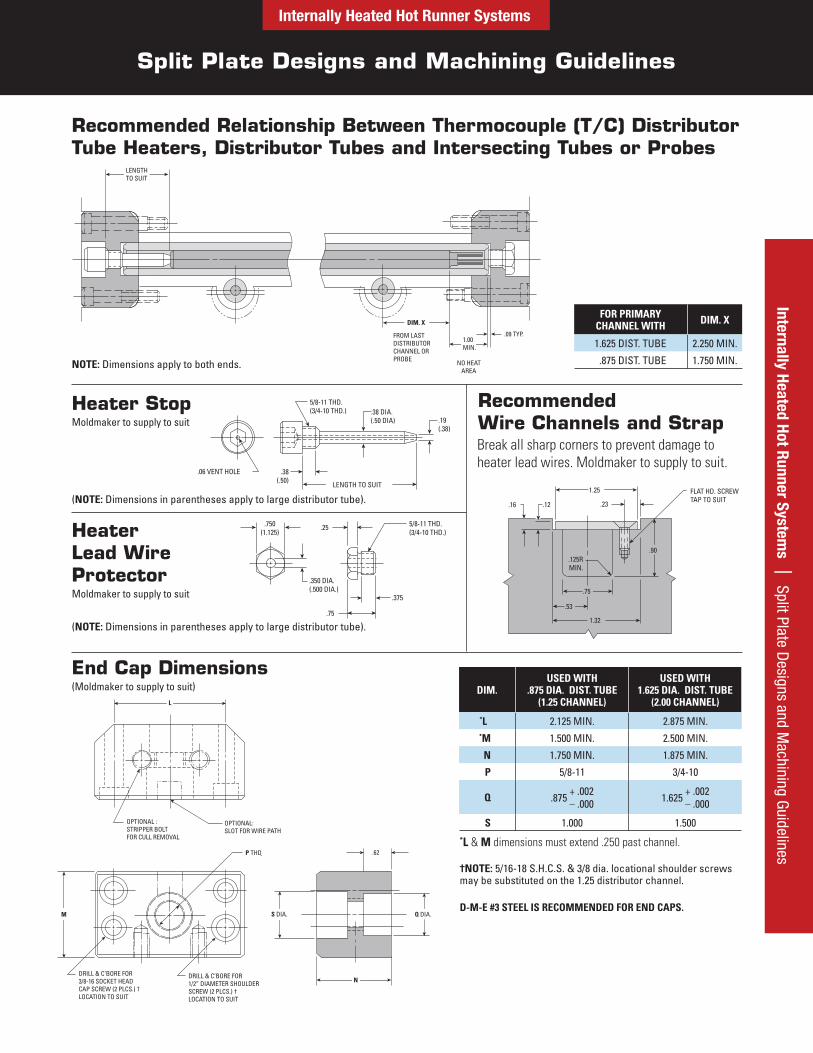
Recommended Relationship Between Thermocouple (T/C) Distributor Tube Heaters, Distributor Tubes and Intersecting Tubes or Probes
NOTE: Dimensions apply to both ends.
FOR PRIMARY CHANNEL WITH DIM. X
1.625 DIST. TUBE 2.250 MIN.
.875 DIST. TUBE 1.750 MIN.
Heater Lead Wire ProtectorMoldmaker to supply to suit
Heater StopMoldmaker to supply to suit
End Cap Dimensions(Moldmaker to supply to suit) DIM.
USED WITH .875 DIA. DIST. TUBE
(1.25 CHANNEL)
USED WITH 1.625 DIA. DIST. TUBE
(2.00 CHANNEL)*L 2.125 MIN. 2.875 MIN.*M 1.500 MIN. 2.500 MIN.
N 1.750 MIN. 1.875 MIN.
P 5/8-11 3/4-10
Q .875 + .002
– .000 1.625 + .002
– .000
S 1.000 1.500
†NOTE: 5/16-18 S.H.C.S. & 3/8 dia. locational shoulder screwsmay be substituted on the 1.25 distributor channel.
D-M-E #3 STEEL IS RECOMMENDED FOR END CAPS.
*L & M dimensions must extend .250 past channel.
.06 VENT HOLE .38(.50)
5/8-11 THD.(3/4-10 THD.) .38 DIA.
(.50 DIA) .19(.38)
LENGTH TO SUIT
.750(1.125)
.25
.350 DIA.(.500 DIA.)
5/8-11 THD.(3/4-10 THD.)
.375
.75
FLAT HD. SCREW TAP TO SUIT
.23.12.16
.125RMIN.
1.25
.90
.75
.53
1.32
Recommended Wire Channels and StrapBreak all sharp corners to prevent damage to heater lead wires. Moldmaker to supply to suit.
(NOTE: Dimensions in parentheses apply to large distributor tube).
(NOTE: Dimensions in parentheses apply to large distributor tube).
Inte
rnal
ly H
eate
d Ho
t Run
ner
Syst
ems
| D
imen
sion
s fo
r Pro
be M
achi
ning
and
Set
-up
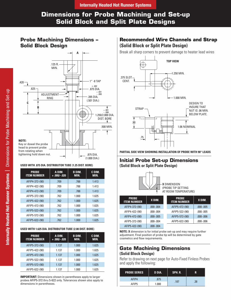
Dimensions for Probe Machining and Set-upSolid Block and Split Plate Designs
Internally Heated Hot Runner Systems
A
BC
.125 R.MIN.
1“ -8 TAP
.875 DIA.+ .001
.000
.002
+ .001 .000
.395 DIA.(.501 DIA.)
.500 MIN.
.875 DIA.(1.000 DIA.)
ADJUSTMENTRING
.625
.420
1.250/2.000 DIA.DIST. BORE
Recommended Wire Channels and Strap(Solid Block or Split Plate Design)Break all sharp corners to prevent damage to heater lead wires
Initial Probe Set-up Dimensions(Solid Block or Split Plate Design)
PROBE ITEM NUMBER X DIM.
AFlP4-372-(90) .000-.004
AFlP4-422-(90) .000-.004
AFlP4-472-(90) .000-.005
AFlP5-372-(90) .000-.004
AFlP5-422-(90) .000-.004
PROBE ITEM NUMBER X DIM.
AFlP5-472-(90) .000-.005
AFlP5-522-(90) .000-.005
AFlP5-572-(90) .000-.006
AFlP5-622-(90) .000-.006
NOTE: X dimension is for initial probe set-up and may require further adjustment. Final position of probe tip will be determined by gate cosmetics and flow requirements.
PROBE SERIES D DIA. SPH. R. R
AFlP4 .875.187 .38
AFlP5 1.000
USED WITH .875 DIA. DISTRIBUTOR TUBE (1.25 DIST. BORE)
USED WITH 1.625 DIA. DISTRIBUTOR TUBE (2.00 DIST. BORE)
Probe Machining Dimensions – Solid Block Design
PROBE ITEM NUMBER
A DIM. + .000/–.020
B DIM. MIN.
C DIM. MIN.
AFIP4-372-(90) .709 .788 1.413
AFIP4-422-(90) .709 .788 1.413
AFIP4-472-(90) .709 .788 1.413
AFIP5-372-(90) .762 1.000 1.625
AFIP5-422-(90) .762 1.000 1.625
AFIP5-472-(90) .762 1.000 1.625
AFIP5-522-(90) .762 1.000 1.625
AFIP5-572-(90) .762 1.000 1.625
AFIP5-622-(90) .762 1.000 1.625
PROBE ITEM NUMBER
A DIM. + .000/–.020
B DIM. MIN.
C DIM. MIN.
AFIP5-372-(90) 1.137 1.000 1.625
AFIP5-422-(90) 1.137 1.000 1.625
AFIP5-472-(90) 1.137 1.000 1.625
AFIP5-522-(90) 1.137 1.000 1.625
AFIP5-572-(90) 1.137 1.000 1.625
AFIP5-622-(90) 1.137 1.000 1.625
NOTE: Key or dowel the probe head to prevent probe from rotating when tightening hold down nut.
IMPORTANT: Dimensions shown in parentheses apply to larger probes AFIP5-372 thru 5-622 only. Tolerances shown also apply to dimensions in parentheses.
Gate Machining Dimensions(Solid Block Design)Refer to drawing on next page for Auto-Fixed Finless Probes and apply the following:
TOP VIEW
1.250 MIN.
1.000 MIN.
.375 SLOTCENT.
STRAP
.90
.75
DESIGN TO INSURE THAT NUT IS .06 MIN. BELOW PLATE.
1.06 NOMINAL
X DIMENSION(PROBE TIP SETTINGAT ROOM TEMPERATURE)
PARTIAL SIDE VIEW SHOWING INSTALLATION OF PROBE WITH 90° LEADS
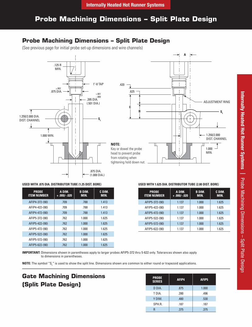
Probe Machining Dimensions – Split Plate Design
Internally Heated Hot Runner SystemsInternally Heated Hot Runner System
s | Probe Machining D
imensions – Split Plate D
esign
USED WITH .875 DIA. DISTRIBUTOR TUBE (1.25 DIST. BORE) USED WITH 1.625 DIA. DISTRIBUTOR TUBE (2.00 DIST. BORE)
Probe Machining Dimensions – Split Plate Design(See previous page for initial probe set-up dimensions and wire channels)
NOTE: The symbol “SL“ is used to show the split line. Dimensions shown are common to either round or trapezoid applications.
Gate Machining Dimensions (Split Plate Design)
PROBE SERIES AFIP4 AFIP5
D DIA. .875 1.000
T DIA. .390 .496
Y DIM. .480 .530
SPH.R. .187 .187
R .375 .375
.125 RMIN.
.875 DIA.
1"-8 TAP
+.001–.000
±.002
.395 DIA.(.501 DIA.)
SL
.875 DIA.(1.000 DIA.)
1.250/2.000 DIA.DIST. CHANNEL
1.000 MIN.
.420
.625
ADJUSTMENT RING
1.250/2.000DIST. CHANNEL
1.000MIN.
A
CB SL
PROBE ITEM NUMBER
A DIM. + .000/–.020
B DIM. MIN.
C DIM. MIN.
AFIP4-372-(90) .709 .788 1.413
AFIP4-422-(90) .709 .788 1.413
AFIP4-472-(90) .709 .788 1.413
AFIP5-372-(90) .762 1.000 1.625
AFIP5-422-(90) .762 1.000 1.625
AFIP5-472-(90) .762 1.000 1.625
AFIP5-522-(90) .762 1.000 1.625
AFIP5-572-(90) .762 1.000 1.625
AFIP5-622-(90) .762 1.000 1.625
PROBE ITEM NUMBER
A DIM. + .000/–.020
B DIM. MIN.
C DIM. MIN.
AFIP5-372-(90) 1.137 1.000 1.625
AFIP5-422-(90) 1.137 1.000 1.625
AFIP5-472-(90) 1.137 1.000 1.625
AFIP5-522-(90) 1.137 1.000 1.625
AFIP5-572-(90) 1.137 1.000 1.625
AFIP5-622-(90) 1.137 1.000 1.625
NOTE: Key or dowel the probe head to prevent probe from rotating when tightening hold down nut.
IMPORTANT: Dimensions shown in parentheses apply to larger probes AFIP5-372 thru 5-622 only. Tolerances shown also apply to dimensions in parentheses.
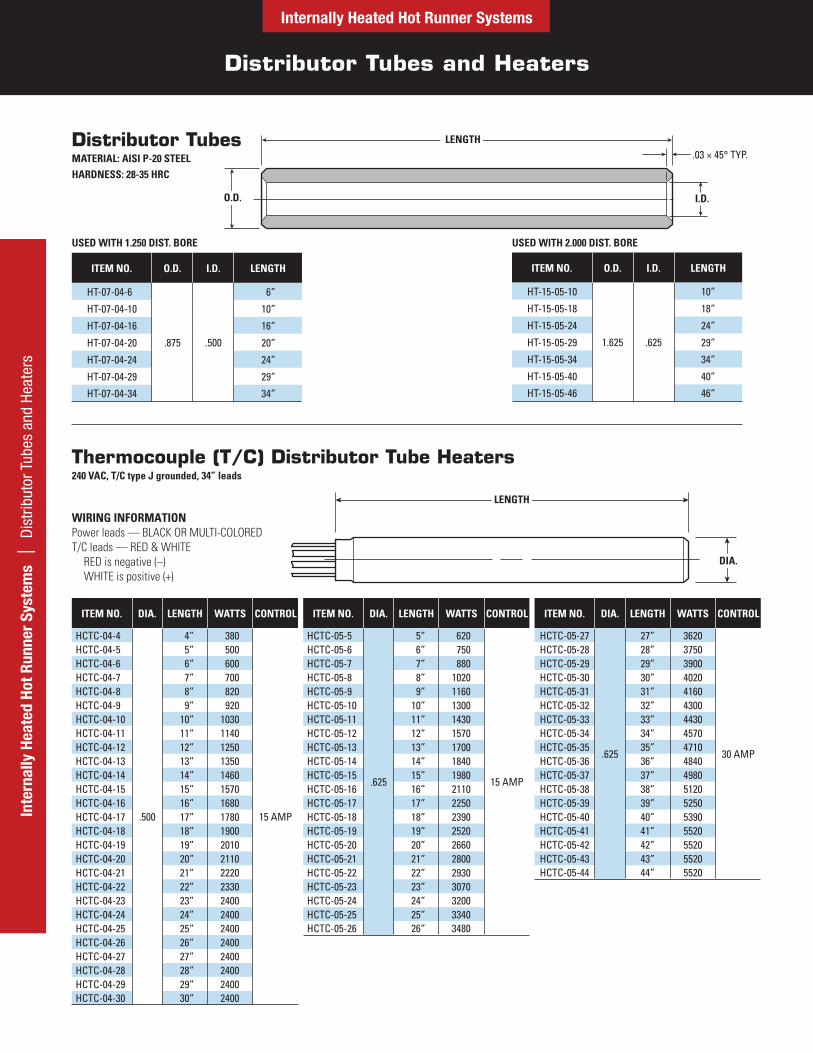
Distributor Tubes and Heaters
Internally Heated Hot Runner SystemsIn
tern
ally
Hea
ted
Hot R
unne
r Sy
stem
s |
Dis
trib
utor
Tub
es a
nd H
eate
rs
Distributor TubesMATERIAL: AISI P-20 STEELHARDNESS: 28-35 HRC
Thermocouple (T/C) Distributor Tube Heaters240 VAC, T/C type J grounded, 34” leads
WIRING INFORMATIONPower leads — BLACK OR MULTI-COLORED T/C leads — RED & WHITE
RED is negative (–) WHITE is positive (+)
ITEM NO. DIA. LENGTH WATTS CONTROL
HCTC-05-5
.625
5” 620
15 AMP
HCTC-05-6 6” 750HCTC-05-7 7” 880HCTC-05-8 8” 1020HCTC-05-9 9” 1160HCTC-05-10 10” 1300HCTC-05-11 11” 1430HCTC-05-12 12” 1570HCTC-05-13 13” 1700HCTC-05-14 14” 1840HCTC-05-15 15” 1980HCTC-05-16 16” 2110HCTC-05-17 17” 2250HCTC-05-18 18” 2390HCTC-05-19 19” 2520HCTC-05-20 20” 2660HCTC-05-21 21” 2800HCTC-05-22 22” 2930HCTC-05-23 23” 3070HCTC-05-24 24” 3200HCTC-05-25 25” 3340HCTC-05-26 26” 3480
ITEM NO. DIA. LENGTH WATTS CONTROL
HCTC-04-4
.500
4” 380
15 AMP
HCTC-04-5 5” 500HCTC-04-6 6” 600HCTC-04-7 7” 700HCTC-04-8 8” 820HCTC-04-9 9” 920HCTC-04-10 10” 1030HCTC-04-11 11” 1140HCTC-04-12 12” 1250HCTC-04-13 13” 1350HCTC-04-14 14” 1460HCTC-04-15 15” 1570HCTC-04-16 16” 1680HCTC-04-17 17” 1780HCTC-04-18 18” 1900HCTC-04-19 19” 2010HCTC-04-20 20” 2110HCTC-04-21 21” 2220HCTC-04-22 22” 2330HCTC-04-23 23” 2400HCTC-04-24 24” 2400HCTC-04-25 25” 2400HCTC-04-26 26” 2400HCTC-04-27 27” 2400HCTC-04-28 28” 2400HCTC-04-29 29” 2400HCTC-04-30 30” 2400
ITEM NO. DIA. LENGTH WATTS CONTROL
HCTC-05-27
.625
27” 3620
30 AMP
HCTC-05-28 28” 3750HCTC-05-29 29” 3900HCTC-05-30 30” 4020HCTC-05-31 31” 4160HCTC-05-32 32” 4300HCTC-05-33 33” 4430HCTC-05-34 34” 4570HCTC-05-35 35” 4710HCTC-05-36 36” 4840HCTC-05-37 37” 4980HCTC-05-38 38” 5120HCTC-05-39 39” 5250HCTC-05-40 40” 5390HCTC-05-41 41” 5520HCTC-05-42 42” 5520HCTC-05-43 43” 5520HCTC-05-44 44” 5520
LENGTH
O.D.
.03 × 45° TYP.
I.D.
LENGTH
DIA.
ITEM NO. O.D. I.D. LENGTH
HT-07-04-6
.875 .500
6”
HT-07-04-10 10”
HT-07-04-16 16”
HT-07-04-20 20”
HT-07-04-24 24”
HT-07-04-29 29”
HT-07-04-34 34”
USED WITH 1.250 DIST. BORE
ITEM NO. O.D. I.D. LENGTH
HT-15-05-10
1.625 .625
10”
HT-15-05-18 18”
HT-15-05-24 24”
HT-15-05-29 29”
HT-15-05-34 34”
HT-15-05-40 40”
HT-15-05-46 46”
USED WITH 2.000 DIST. BORE
Nozzle Locator Assemblies, Cores and Heaters
Internally Heated Hot Runner SystemsInternally Heated Hot Runner System
s | Nozzle Locator Assem
blies, Cores and Heaters
Heated Nozzle Locator Assemblies
HNL-462 and HNL-662 assemblies include:HNC-46 or HNC-66 core, respectivelySSTC-62-90 heaterHNS-67 spacer (stainless steel)
HNL-472 and HNL-672 assemblies include:HNC-47 or HNC-67 core, respectivelySSTC-72-90 heaterHNS-67 spacer (stainless steel)
•••
•••
Replacement Nozzle Locator Cores(See drawing at left for A Dim. reference and detail)
ITEM NUMBERA DIM.
R = 1⁄2 R = 3⁄4
HNC-46 HNC-66 1.809
HNC-47 HNC-67 2.309
Replacement Thermocouple (T/C) Square Coil Nozzle Locator Heaters(240 VAC, 250 Watts, T/C type J grounded, 34” leads)
ITEM NO. B DIM. USED WITH
SSTC-62-90 1.450 HNC-46 & HNC-66 Cores
SSTC-72-90 1.950 HNC-47 & HNC-67 Cores
.71
.75 MIN.
.75 DIA.
B
ITEM NO.A DIM. B DIM.
R = 1⁄2 R = 3⁄4
HNL-462 HNL-662 1.809 1.450
HNL-472 HNL-672 2.309 1.950
WIRING INFORMATIONPower leads — BLACK OR MULTI-COLORED T/C leads — RED & WHITE
RED is negative (–) WHITE is positive (+)
¼-20 TAPPED HOLES(2 PLACES) DRILLED AND C’ SUNK
FOR ¼-20 S.H.C.S.(2 PLACES)
1.437 DIA.BOLT CIRCLE
CORE
1.970DIA.
.750 DIA.HEATERREF.
.500 DIA.
.312 DIA.
R
HEATER
.375
BA
.71
STAINLESS STEELSPACER(See detail below)
End Caps, Nozzle Locators and Spacer
Internally Heated Hot Runner SystemsIn
tern
ally
Hea
ted
Hot R
unne
r Sy
stem
s |
End
Cap
s, N
ozzl
e Lo
cato
rs a
nd S
pace
r
D
1.437 DIA.BOLT CIRCLE
C
.30
45°
45°
.219
1.250 (As Supplied)
2.250DIA.
1.062DIA.
1.970DIA.
1.970DIA.REF.
DRILLED AND C’SUNK FOR1/4-20 FLAT HEAD SCREW2 PLACES
1/4-20 TAPPED HOLES2 PLACES
1.312 R.
.313 DIA.
.50 SPH. R.
.313
.015
3.250 DIA.
+.000–.005
+.00–.01
1.995 DIA.
.63
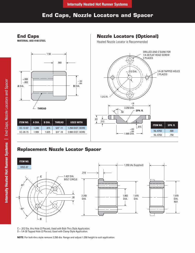
End CapsMATERIAL: AISI 4140 STEEL
ITEM NO. A DIA. B DIA. THREAD USED WITH
EC-12-07 1.249 .875 5/8”-11 1.250 DIST. BORE
EC-20-15 1.999 1.625 3/4”-10 2.000 DIST. BORE
Nozzle Locators (Optional)Heated Nozzle Locator is Recommended
ITEM NO. SPH. R.
NL-6702 .500
NL-6703 .750
Replacement Nozzle Locator Spacer
ITEM NO.
HNS-67
NOTE: For bolt-thru style remove 2.250 dia. flange and adjust 1.250 height to suit application.
C = .312 Dia. thru Hole (2 Places), Used with Bolt-Thru Style Application. D = 1/4-20 Tapped Hole (2 Places), Used with Clamp Style Application.
.560
+.000–.002
THREAD
+ .002–.000
A DIA.
1.50
B DIA.
Internally Heated Hot Runner Systems
Probes and Gate Insert Applications
Internally Heated Hot Runner Systems | Probes and Gate Insert Applications
10° TYP..06 TYP.
120° TPY.
+.001–.000
+.000–.001 +.000
–.001
C DIA.
.125A DIA.
B DIA.
REGISTER RING(Optional)
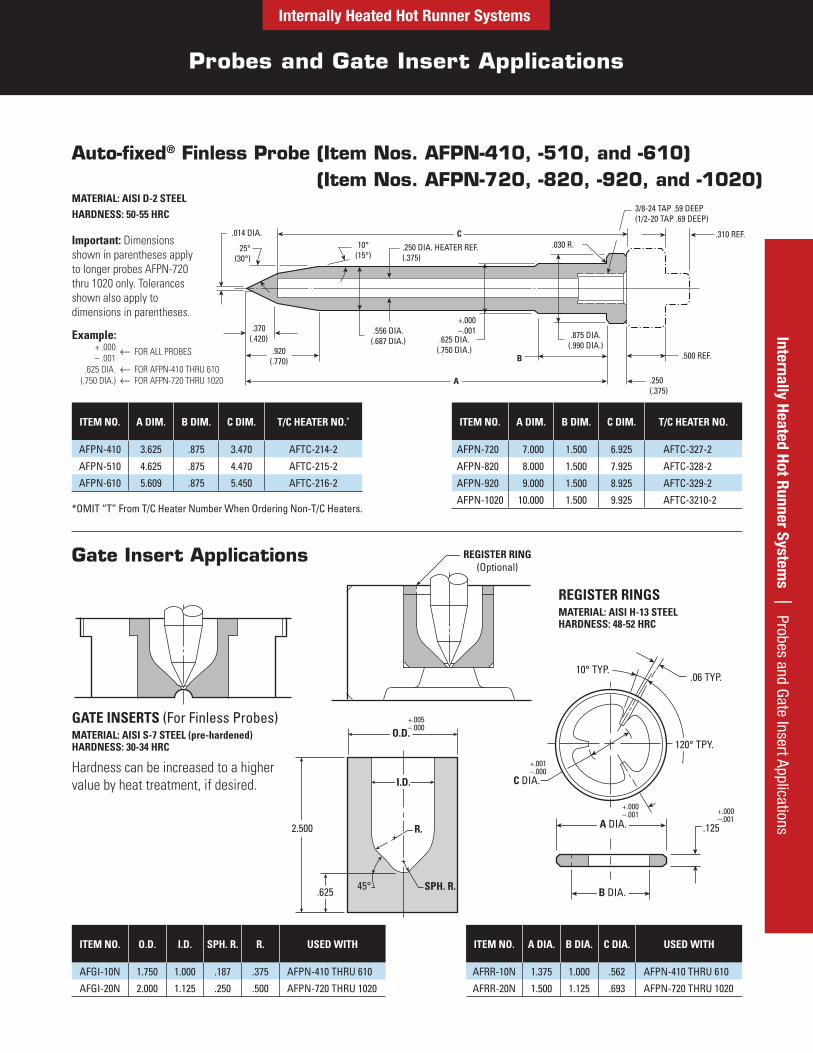
Auto-fixed® Finless Probe (Item Nos. AFPN-410, -510, and -610) (Item Nos. AFPN-720, -820, -920, and -1020)
MATERIAL: AISI D-2 STEELHARDNESS: 50-55 HRC
ITEM NO. A DIM. B DIM. C DIM. T/C HEATER NO.*
AFPN-410 3.625 .875 3.470 AFTC-214-2
AFPN-510 4.625 .875 4.470 AFTC-215-2
AFPN-610 5.609 .875 5.450 AFTC-216-2
ITEM NO. A DIM. B DIM. C DIM. T/C HEATER NO.
AFPN-720 7.000 1.500 6.925 AFTC-327-2
AFPN-820 8.000 1.500 7.925 AFTC-328-2
AFPN-920 9.000 1.500 8.925 AFTC-329-2
AFPN-1020 10.000 1.500 9.925 AFTC-3210-2
Gate Insert Applications
GATE INSERTS (For Finless Probes)MATERIAL: AISI S-7 STEEL (pre-hardened) HARDNESS: 30-34 HRC
Hardness can be increased to a higher value by heat treatment, if desired.
REGISTER RINGSMATERIAL: AISI H-13 STEEL HARDNESS: 48-52 HRC
ITEM NO. O.D. I.D. SPH. R. R. USED WITH
AFGI-10N 1.750 1.000 .187 .375 AFPN-410 THRU 610
AFGI-20N 2.000 1.125 .250 .500 AFPN-720 THRU 1020
ITEM NO. A DIA. B DIA. C DIA. USED WITH
AFRR-10N 1.375 1.000 .562 AFPN-410 THRU 610
AFRR-20N 1.500 1.125 .693 AFPN-720 THRU 1020
.014 DIA.
25°(30°)
10°(15°)
.250 DIA. HEATER REF.(.375)
.030 R.
3/8-24 TAP .59 DEEP(1/2-20 TAP .69 DEEP)
.310 REF.
.500 REF.
.250(.375)
.370(.420)
.556 DIA.(.687 DIA.)
+.000–.001
.625 DIA.(.750 DIA.)
B
.875 DIA.(.990 DIA.)
.920(.770)
C
A
SPH. R.
R.
45°
2.500
+.005–.000
.625
I.D.
O.D.
*OMIT “T” From T/C Heater Number When Ordering Non-T/C Heaters.
Important: Dimensions shown in parentheses apply to longer probes AFPN-720 thru 1020 only. Tolerances shown also apply to dimensions in parentheses.
Example:+ .000– .001
FOR ALL PROBES
.625 DIA. FOR AFPN-410 THRU 610(.750 DIA.) FOR AFPN-720 THRU 1020
Probes and Gate Insert Applications
Internally Heated Hot Runner SystemsIn
tern
ally
Hea
ted
Hot R
unne
r Sy
stem
s |
Pro
bes
and
Gate
Inse
rt A
pplic
atio
ns
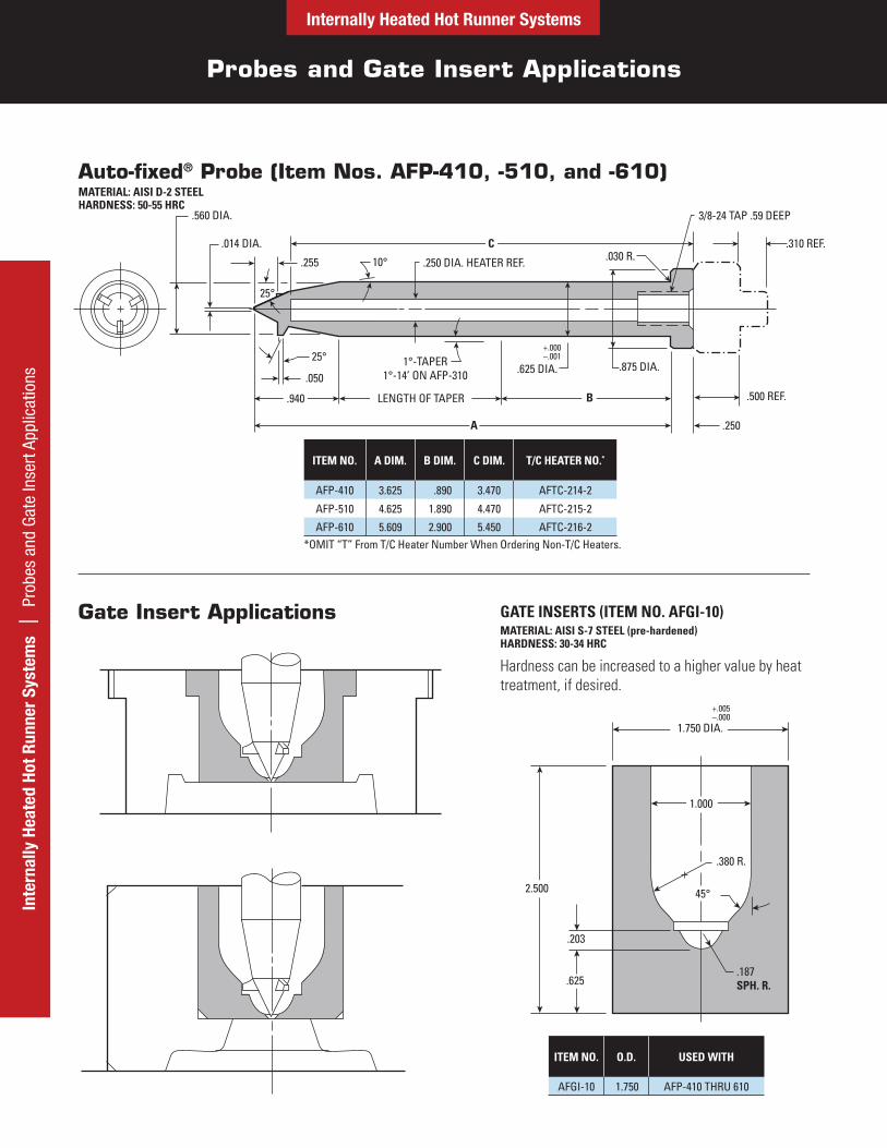
Auto-fixed® Probe (Item Nos. AFP-410, -510, and -610)MATERIAL: AISI D-2 STEEL HARDNESS: 50-55 HRC
ITEM NO. A DIM. B DIM. C DIM. T/C HEATER NO.*
AFP-410 3.625 .890 3.470 AFTC-214-2
AFP-510 4.625 1.890 4.470 AFTC-215-2
AFP-610 5.609 2.900 5.450 AFTC-216-2
GATE INSERTS (ITEM NO. AFGI-10)MATERIAL: AISI S-7 STEEL (pre-hardened) HARDNESS: 30-34 HRC
Hardness can be increased to a higher value by heat treatment, if desired.
ITEM NO. O.D. USED WITH
AFGI-10 1.750 AFP-410 THRU 610
Gate Insert Applications
.560 DIA.
.014 DIA.
.255 10°
25°
.250 DIA. HEATER REF. .030 R.
3/8-24 TAP .59 DEEP
.310 REF.
25°
.0501°-TAPER
1°-14’ ON AFP-310
+.000–.001
.625 DIA. .875 DIA.
.500 REF.
.250
.940 LENGTH OF TAPER B
A
C
.203
.380 R.
45°
.187SPH. R.
1.750 DIA.
1.000
.625
2.500
+.005–.000
*OMIT “T” From T/C Heater Number When Ordering Non-T/C Heaters.
Probe Heaters and Components
Internally Heated Hot Runner SystemsInternally Heated Hot Runner System
s | Probe Heaters and Components
ITEM NUMBER* FOR PROBE WATTS LENGTH
AFTC-214-2 AFP(N)-410 220 3.75
AFTC-215-2 AFP(N)-510 275 4.75
AFTC-216-2 AFP(N)-610 350 5.75
.250 DIA. (240 VAC, T/C type J grounded, 34” leads)
*OMIT “T” From T/C Heater Number When Ordering Non-T/C Heaters.
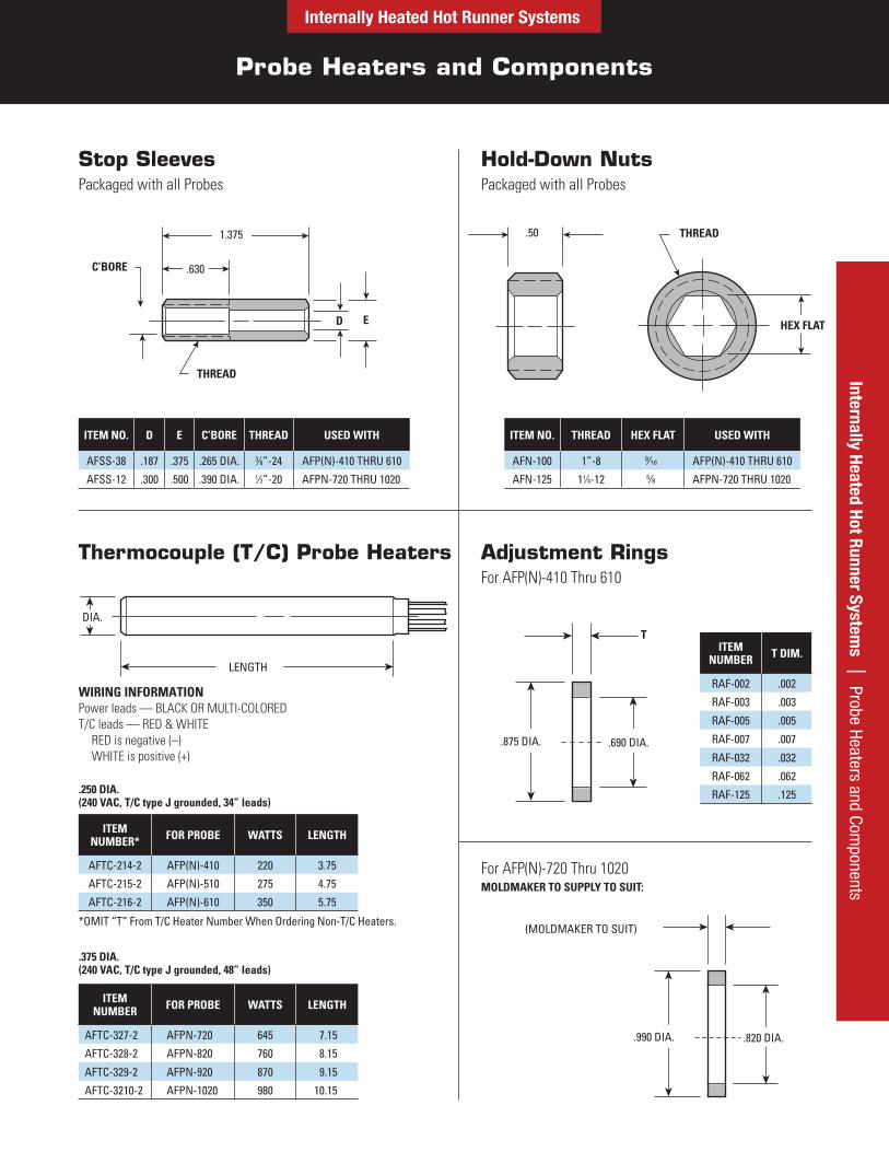
Stop SleevesPackaged with all Probes
Hold-Down NutsPackaged with all Probes
ITEM NO. D E C’BORE THREAD USED WITH
AFSS-38 .187 .375 .265 DIA. 3⁄8”-24 AFP(N)-410 THRU 610
AFSS-12 .300 .500 .390 DIA. 1⁄2”-20 AFPN-720 THRU 1020
ITEM NO. THREAD HEX FLAT USED WITH
AFN-100 1”-8 9⁄16 AFP(N)-410 THRU 610
AFN-125 11⁄4-12 5⁄8 AFPN-720 THRU 1020
Thermocouple (T/C) Probe Heaters
ITEM NUMBER FOR PROBE WATTS LENGTH
AFTC-327-2 AFPN-720 645 7.15
AFTC-328-2 AFPN-820 760 8.15
AFTC-329-2 AFPN-920 870 9.15
AFTC-3210-2 AFPN-1020 980 10.15
Adjustment RingsFor AFP(N)-410 Thru 610
For AFP(N)-720 Thru 1020MOLDMAKER TO SUPPLY TO SUIT:
THREAD
C’BORE
D E
1.375
.630
.50 THREAD
HEX FLAT
DIA.
LENGTH
ITEM NUMBER T DIM.
RAF-002 .002
RAF-003 .003
RAF-005 .005
RAF-007 .007
RAF-032 .032
RAF-062 .062
RAF-125 .125
.875 DIA. .690 DIA.
T
(MOLDMAKER TO SUIT)
.990 DIA. .820 DIA.
.375 DIA. (240 VAC, T/C type J grounded, 48” leads)
WIRING INFORMATIONPower leads — BLACK OR MULTI-COLORED T/C leads — RED & WHITE
RED is negative (–) WHITE is positive (+)
Internally Heated Hot Runner Systems
Solid Distributor Block Design and Machining Guidelines
Inte
rnal
ly H
eate
d Ho
t Run
ner
Syst
ems
| S
olid
Dis
trib
utor
Blo
ck –
Des
ign
and
Mac
hini
ng G
uide
lines
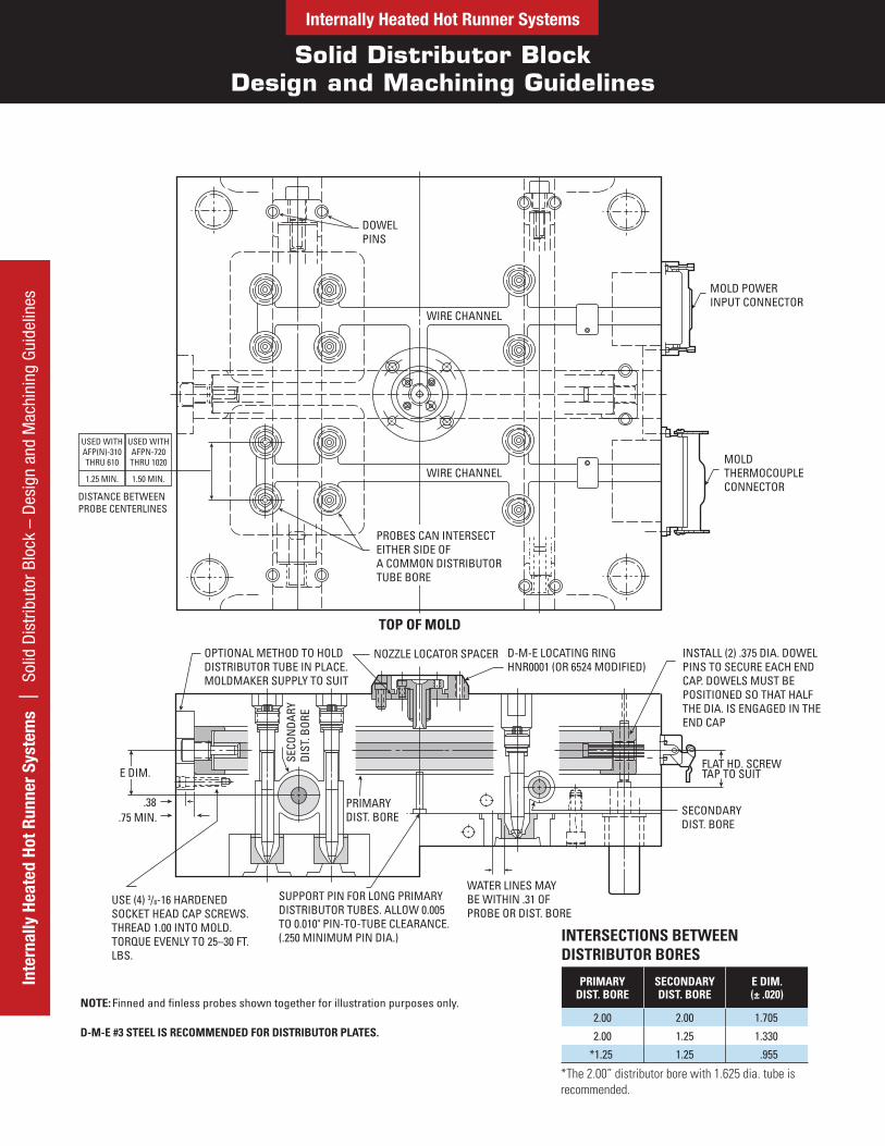
DOWELPINS
WIRE CHANNEL
WIRE CHANNEL
MOLD POWERINPUT CONNECTOR
MOLDTHERMOCOUPLECONNECTOR
TOP OF MOLD
PROBES CAN INTERSECTEITHER SIDE OFA COMMON DISTRIBUTORTUBE BORE
SUPPORT PIN FOR LONG PRIMARYDISTRIBUTOR TUBES. ALLOW 0.005TO 0.010" PIN-TO-TUBE CLEARANCE.(.250 MINIMUM PIN DIA.)
OPTIONAL METHOD TO HOLD DISTRIBUTOR TUBE IN PLACE.MOLDMAKER SUPPLY TO SUIT
NOZZLE LOCATOR SPACER D-M-E LOCATING RING HNR0001 (OR 6524 MODIFIED)
INSTALL (2) .375 DIA. DOWELPINS TO SECURE EACH END CAP. DOWELS MUST BE POSITIONED SO THAT HALFTHE DIA. IS ENGAGED IN THE END CAP
WATER LINES MAYBE WITHIN .31 OF PROBE OR DIST. BORE
USE (4) 3/8-16 HARDENEDSOCKET HEAD CAP SCREWS.THREAD 1.00 INTO MOLD.TORQUE EVENLY TO 25–30 FT.LBS.
.38.75 MIN.
SECO
NDA
RYDI
ST. B
ORE
PRIMARYDIST. BORE
FLAT HD. SCREWTAP TO SUIT
SECONDARYDIST. BORE
E DIM.
USED WITH AFP(N)-310 THRU 610
1.25 MIN.
USED WITH AFPN-720 THRU 1020
1.50 MIN.
DISTANCE BETWEEN PROBE CENTERLINES
INTERSECTIONS BETWEEN DISTRIBUTOR BORES
NOTE: Finned and finless probes shown together for illustration purposes only.
D-M-E #3 STEEL IS RECOMMENDED FOR DISTRIBUTOR PLATES.
PRIMARY DIST. BORE
SECONDARY DIST. BORE
E DIM. (± .020)
2.00 2.00 1.705
2.00 1.25 1.330
*1.25 1.25 .955
*The 2.00” distributor bore with 1.625 dia. tube is recommended.
Internally Heated Hot Runner Systems | Solid D
istributor Block – Design and M
achining GuidelinesSolid Distributor Block
Design and Machining Guidelines
Internally Heated Hot Runner Systems
.500 MAX.
1.437 DIA.BOLT CIRCLE
NOZZLELOCATOR SPACER
.500 MIN.
D.M.E LOCATINGRING HNR0001(OR 6524 MODIFIED)
.156REF.
.06 FROM DIST. TUBE
45°
BWA
NOZZLELOCATOR SPACER D-M-E LOCATING
RING 6521
.06 FROM DIST. TUBE
.156REF.
A
.500 MIN.
W
.219125RMIN.
SHOWN OUTOF POSITION
.06 × 45°CHAMF.
.5000
.5005DIA.
1.06 DIA.
15°.156.06R
VW
Heated Nozzle Locator
ALL APPLICATIONSThe locator’s core tip should be positioned 0.060 from the top of the distributor tube, establishing the “A“ dimension. In most cases, the dimension from the bottom of the core head to the locating ring counterbore will equal the adjusted height of the spacer. (The “B“ dimension, for reference, is the heater length of 1.450 or 1.950, depending on core length being used.)
CLAMP STYLE SPACER APPLICATION (Figure 1)The spacer is supplied with a flange and a 1.250 height. The flange may be used in conjunction with a D-M-E HNR0001 or modified 6524 locating ring to form a clamp-style spacer. To modify the locating ring, enlarge its 2.00 diameter counterbore to 2.281 (0.219 deep) and its 1.75 I.D. to 2.00. The core is secured to the spacer with two 1/4-20 S.H.C.S.
BOLT THRU STYLE SPACER APPLICATION (Figure 2)Another option is to remove the flange and adjust the spacer height to the desired dimension, then secure the Heated Nozzle Locator through the spacer with two 1/4-20 S.H.C.S.
into the mold plate. Use caution to insure that the tapped holes are 0.500 minimum from the distributor channel.Spacer thickness should never be less than 0.250. However, if a condition results where the spacer would be less than 0.250, counterbore a 2.00 diameter into the plate to a “V“ depth that will accept the 0.250 spacer (see Figure 3).
ALL APPLICATIONSIn order to maintain plate strength, the depth of the lead wire channel, dimension “W“, must be no deeper than required to contain the heater leads. The distance from the bottom of the core head to the bottom of the heater leads is 0.800. Channel depth can be determined accordingly, based on the distance between the core head and the top of the mold.
If a condition occurs where the Heated Nozzle Locator would extend above the standard locating ring, a special locating ring with extended flange for protecting the Heated Nozzle Locator should be constructed.
FIGURE 1
FIGURE 3
FIGURE 2
Inte
rnal
ly H
eate
d Ho
t Run
ner
Syst
ems
| S
olid
Dis
trib
utor
Blo
ck D
esig
n an
d M
achi
ning
Gui
delin
es
Solid Distributor Block Design and Machining Guidelines
Internally Heated Hot Runner Systems
The design guidelines in this document serve as production-proven recommendations of the D-M-E Hot Runner System, and are ONLY applicable to the current line of D-M-E components. The guidelines and component details in this document supersede all previous documents. Due to the wide variety of plastics materials and possible molding applications available, no warranties are expressed or implied. D-M-E Hot Runner System Components are manufactured and sold under one or more of the following U.S. patents: 3,767,340; 3,010,155; 3,023,458; 3,231,938 and 3,758,248. Foreign patents issued and pending.
.19 DIA.
.38 DIA.
+
+
LENGTH TO SUIT
.88
FROM LAST DISTRIBUTOR
CHANNEL OR PROBE
MIN.NO HEAT AREA
.09 TYP.
DIM. X 1.00
.150 REF.
+
+
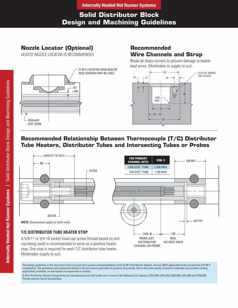
T/C DISTRIBUTOR TUBE HEATER STOPA 5/8-11 or 3/4-10 socket head cap screw (thread based on end cap being used) is recommended to serve as a positive heater stop. One stop is required for each T/C distributor tube heater. Moldmaker supply to suit.
Nozzle Locator (Optional)HEATED NOZZLE LOCATOR IS RECOMMENDED
PRIMARYDIST. BORE
.187±.005
D-M-E LOCATING RING 6520 OR6522 (SHOWN) MAY BE USED FLAT HD. SCREW
TAP TO SUIT.23.12.16
.125RMIN.
1.25
.75
.53
1.32
.90
Recommended Relationship Between Thermocouple (T/C) Distributor Tube Heaters, Distributor Tubes and Intersecting Tubes or Probes
FOR PRIMARY CHANNEL WITH DIM. X
1.625 DIST. TUBE 2.250 MIN.
.875 DIST. TUBE 1.750 MIN.
NOTE: Dimensions apply to both ends.
Recommended Wire Channels and StrapBreak all sharp corners to prevent damage to heater lead wires. Moldmaker to supply to suit.
Solid Distributor Block Machining Guidelines
Internally Heated Hot Runner SystemsInternally Heated Hot Runner System
s | Solid Distributor Block M
achining Guidelines
X DIMENSION(PROBE TIP SETTINGAT ROOM TEMPERATURE)GATE DIA. (.040 MIN.)
TO SUIT APPLICATION
.030
.005 MAX. LAND SPH. R.
45°
R.
Y°
D DIA.
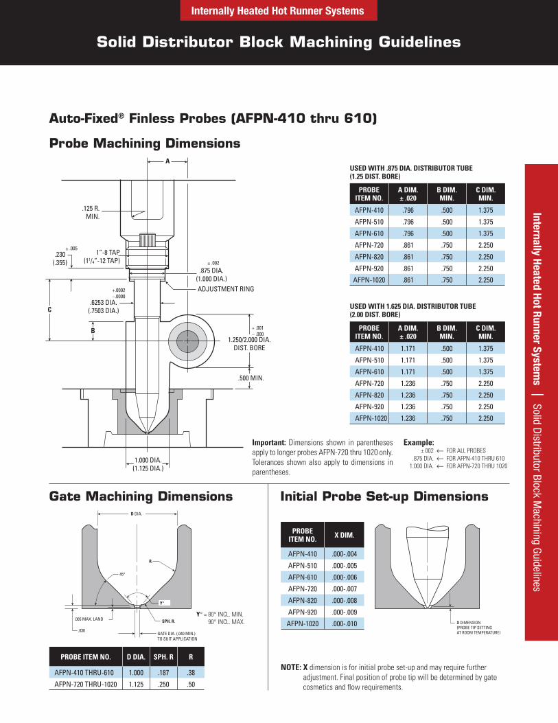
Auto-Fixed® Finless Probes (AFPN-410 thru 610)
Probe Machining Dimensions
PROBE ITEM NO.
A DIM. ± .020
B DIM. MIN.
C DIM. MIN.
AFPN-410 .796 .500 1.375
AFPN-510 .796 .500 1.375
AFPN-610 .796 .500 1.375
AFPN-720 .861 .750 2.250
AFPN-820 .861 .750 2.250
AFPN-920 .861 .750 2.250
AFPN-1020 .861 .750 2.250
PROBE ITEM NO.
A DIM. ± .020
B DIM. MIN.
C DIM. MIN.
AFPN-410 1.171 .500 1.375
AFPN-510 1.171 .500 1.375
AFPN-610 1.171 .500 1.375
AFPN-720 1.236 .750 2.250
AFPN-820 1.236 .750 2.250
AFPN-920 1.236 .750 2.250
AFPN-1020 1.236 .750 2.250
Important: Dimensions shown in parentheses apply to longer probes AFPN-720 thru 1020 only. Tolerances shown also apply to dimensions in parentheses.
Example:± 002 FOR ALL PROBES
.875 DIA. FOR AFPN-410 THRU 6101.000 DIA. FOR AFPN-720 THRU 1020
Gate Machining Dimensions Initial Probe Set-up Dimensions
PROBE ITEM NO. X DIM.
AFPN-410 .000-.004
AFPN-510 .000-.005
AFPN-610 .000-.006
AFPN-720 .000-.007
AFPN-820 .000-.008
AFPN-920 .000-.009
AFPN-1020 .000-.010
NOTE: X dimension is for initial probe set-up and may require further adjustment. Final position of probe tip will be determined by gate cosmetics and flow requirements.
PROBE ITEM NO. D DIA. SPH. R R
AFPN-410 THRU-610 1.000 .187 .38
AFPN-720 THRU-1020 1.125 .250 .50
Y° = 80° INCL. MIN. 90° INCL. MAX.
USED WITH .875 DIA. DISTRIBUTOR TUBE (1.25 DIST. BORE)
USED WITH 1.625 DIA. DISTRIBUTOR TUBE (2.00 DIST. BORE)
1.000 DIA.(1.125 DIA.)
.125 R.MIN.
± .005
± .002.230
(.355)1”-8 TAP
(11/4”-12 TAP)
+.0002–.0000
.6253 DIA.(.7503 DIA.)
.875 DIA.(1.000 DIA.)ADJUSTMENT RING
+ .001– .000
.500 MIN.
1.250/2.000 DIA.DIST. BORE
C
A
B
Internally Heated Hot Runner Systems
Solid Distributor Block Machining Guidelines
Inte
rnal
ly H
eate
d Ho
t Run
ner
Syst
ems
| S
olid
Dis
trib
utor
Blo
ck M
achi
ning
Gui
delin
es
.022 MIN.(PROBE FIN CLEARANCE
AT ROOM TEMPERATURE)*
X DIMENSION(PROBE TIP SETTING
AT ROOM TEMPERATURE)
.125 R.MIN.
± .005
1”-8 TAP
± .002
.230
+.0002–.0000
.6253 DIA.
.875
ADJUSTMENT RING
+ .001– .000
1.000 DIA.
1.250/2.000 DIA.DIST. BORE
.500 MIN.
B
C
A
.38R
+.002–.000
.005 R.45°
30°
.085
.203
.233 .030
.005 MAX. LAND
.187 SPH. R.
GATE DIA. (.040 MIN.)TO SUIT APPLICATION
1.000 DIA.
.570 DIA.
Y°
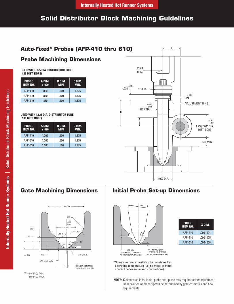
Auto-Fixed® Probes (AFP-410 thru 610)
PROBE ITEM NO.
A DIM. ± .020
B DIM. MIN.
C DIM. MIN.
AFP-410 .830 .500 1.375
AFP-510 .830 .500 1.375
AFP-610 .830 .500 1.375
PROBE ITEM NO.
A DIM. ± .020
B DIM. MIN.
C DIM. MIN.
AFP-410 1.205 .500 1.375
AFP-510 1.205 .500 1.375
AFP-610 1.205 .500 1.375
Gate Machining Dimensions Initial Probe Set-up Dimensions
PROBE ITEM NO. X DIM.
AFP-410 .000-.004
AFP-510 .000-.005
AFP-610 .000-.006
NOTE: X dimension is for initial probe set-up and may require further adjustment. Final position of probe tip will be determined by gate cosmetics and flow requirements.
Y° = 80° INCL. MIN. 90° INCL. MAX.
* Some clearance must also be maintained at operating temperature (i.e. no metal to metalcontact between fin and counterbore).
USED WITH .875 DIA. DISTRIBUTOR TUBE (1.25 DIST. BORE)
USED WITH 1.625 DIA. DISTRIBUTOR TUBE (2.00 DIST. BORE)
Probe Machining Dimensions