Embed Size (px)
DESCRIPTION
The Cornerstone to Test Automation The Media Cross Connect. MRV OCS Fast Facts. Founded in 1988 Over 20 years of optical innovation OCS Group employees 300 + Systems and integration business units Product offerings Infrastructure management Physical Layer Switch - PowerPoint PPT Presentation
Citation preview

The Cornerstone to Test AutomationThe Media Cross Connect

Founded in 1988– Over 20 years of optical innovation
OCS Group employees 300+– Systems and integration business units
Product offerings – Infrastructure management
• Physical Layer Switch
• Console Server/Power Management
– Optical communications
– Network management
– Network integration professional
services
MRV OCS Fast Facts
2
Worldwide Presence
Sales and service offices worldwide

Time to market is critical– Development and test cycle must get shorter
Time to market is critical– Development and test cycle must get shorter
Product/Test complexity is increasing– Testing becoming a burden/bottleneck of release cycle
Test standardization– Accuracy and repeatability more important
Test setup – Time consuming process prone to errors
Optimization of resources – Expensive equipment needs maximum utilization
Challenges with Test Management

Traditional Test Lab Environment
Labor-intense test set up
Prone to human error
Compromises test accuracy and repeatability
Inefficient use of lab equipment
Not positioned for automation
An estimated 70% of testing downtime is caused by wiring mistakes

Media Cross Connect Wire-Once Solution
Wire all infrastructure equipment to the MCC Configure physical connections using software commands
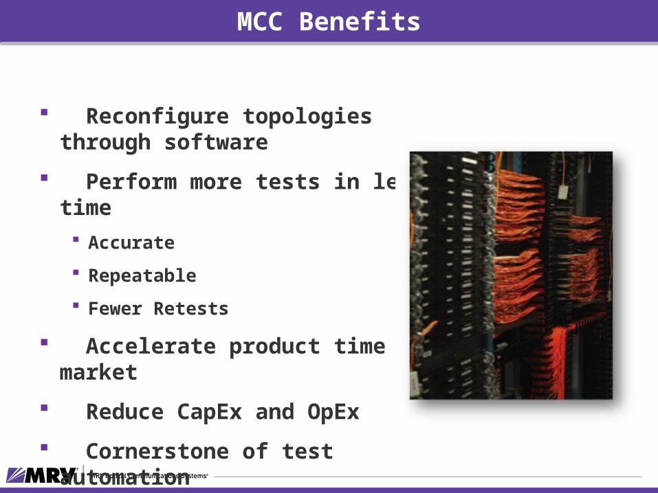
MCC Benefits
Reconfigure topologies through software
Perform more tests in less time Accurate
Repeatable
Fewer Retests
Accelerate product time to market
Reduce CapEx and OpEx
Cornerstone of test automation

MCC Applications
Lab automation Equipment sharing Interoperability testing Network/fault simulation System test/validation Media conversion Proof of concept labs Support labs/NOC Training centers Video matrix distribution/multicast traffic Network monitoring

Reduce test time
Increase test accuracy
Increase equipment utilization
Expedite new product releases
Minimize operational and capital expense
Position for test automation
Why Deploy the MCC ?
8

9
As companies try to do more with less – Test automation is becoming required practice

Cornerstone to Lab Automation
Connect the physical layer using software commandsPoint to point – uni- or bi directionalPoint to multi pointPort mirroring

Layer 1, Physical Layer Switch– Route media electronically
Provides programmable mappings– any-port to any-port, – wire-speed connectivity – non-blocking switching back plane
Port mappings can be made one-to-one or one-to-many Protocol independent - data rate specific 100% transparent with virtually no latency (<μs) Variety of chassis types and interface blades
What is a Media Cross Connect?
11

Physical Layer Switch
12
MCC
OSI Model

Media Cross Connect Hardware Overview
13

MCC Chassis
4X Chassis (4.25G mapping bandwidth)— 2, 4, 8 slot AC/DC
8X Chassis (8.50G mapping bandwidth)— 4 slot AC/DC
High Speed Chassis (10.3Gbps mapping bandwidth)— 1 slot AC, 36 ports x 10G non-blocking — 4 slot AC/DC, up to 144 ports x 10G non-blocking— 8 slot AC, up to 288 port x 10G non-blocking

MCC Interface Blades
Optical andCopper
Interface Blade types•RJ 45 – 100m/1G conversion•T3/E3/STS1•SFP – with and without CDR•SFP+ - up to 10G
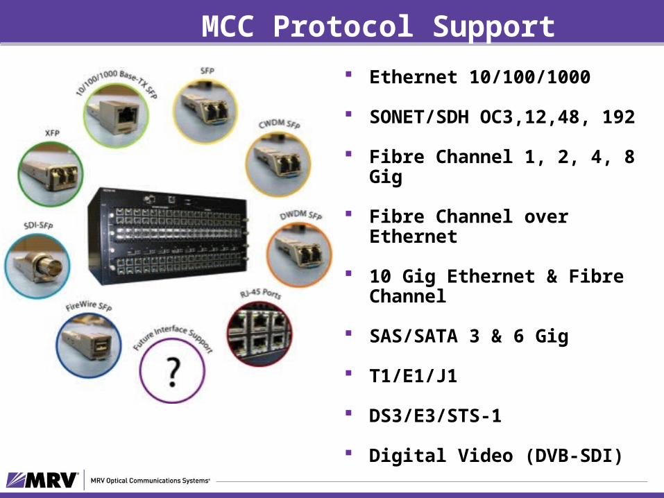
MCC Protocol Support Ethernet 10/100/1000
SONET/SDH OC3,12,48, 192
Fibre Channel 1, 2, 4, 8 Gig
Fibre Channel over Ethernet
10 Gig Ethernet & Fibre Channel
SAS/SATA 3 & 6 Gig
T1/E1/J1
DS3/E3/STS-1
Digital Video (DVB-SDI)

MCC Chassis Offerings
Chassis(NC316-)
BladeSlots
Per Port Mapping Speed
Max # Ports(@ Max Speed)
PowerSupplies Size
36PMC HS 1 10.3 Gbps – HS 36 2 AC 1 RU
72PMC 4X 2 4.25 Gbps – 4X 72(18 – 10G) 2 AC 4 RU
144PMC 4X 4 4.25 Gbps – 4X 144(32 – 10G)
2 ACor 2 DC 5 RU
144PMC 8X 4 8.5 Gbps – 8X 144(8G)
2 ACor 2 DC 5 RU
144PMC HS 4 10.3 Gbps - HS 144(10G)
2 ACor 2 DC 5 RU
288PMC 4X 8 4.25 Gbps – 4X 288(72 – 10G)
4 ACor 4 DC 9 RU
288PMC HS 8 10.3 Gbps – HS 288(10G)
4AC or 4 DC (included) 10 RU
3672
144
288

MCC Chassis Blade Support
Chassis 2R or 3R 36PMCHS 72PMC4X 144PMC4X 144PMC8X 144PMCHS 288PMC4X 288PMCHS
Blades
36 SFP 2R X X X X X X X
36 SFP MR CDR 3R X X X X X X X
36 SFP+ FC 8G 3R X X X X
36 SFP+ 10G MR 3R X X X
9 XFP 10G 3R X X X X X X
36 RJ-C 3R X X X X X X X
36 T1/E1 3R X X X X X X X
18 D3/T3/STS 3R X X X X X
36 SAS/SATA X X X
36 IC (3x12) 3R X X X X X X X
2R = Reshape & Retransmit3R = Reshape, Retransmit & Retime

Pay-as-you-grow Scalability
Multi-use paths eliminate rate matching in clustering configurations Decreases the number of inter-chassis (Z) links and optics Flexible, economical means of achieving large port count connectivity

Inter-Chassis Blade
Three CXPs provide 12 rate-independent paths Simplify design and implementation of multiple chassis Compatible with any MCC chassis MTP cables rated to 100M

504 Ports Using 2 Chassis
12 multi-rate links/cable

1008 Ports Using 5 Chassis
12 multi-rate links/cable

Optical Cross Connect- OCC 96
• Single Mode Physical Layer Switch
• All Optical Switch
• Protocol Independent
• Any Speed Up to 100 Gbps• 1, 10, 40, and 100Gbps
• “Dark Fiber Switching” • doesn’t require end system devices to configure connections
• Standards based management interfaces

96 Ports, SMF Dual LC Connectors Low Loss: <2 dB insertion loss Serial Port, 10/100 Ethernet
Management Port AC or DC Power Options Field replaceable power modules Mechanicals
17.25”x 22”x 8.7” (5RU) Weight 59 lbs. +10°C to 40°C (32°F to 122°F) Heat Dissipation 55W
OCC 96 Specifications

How it works: an optical beam is collimated and steered from an input array ("send" side) to an output array ("receive" side). Voltage signals to the piezoelectric elements control the pointing
Advantages of Beam-steering technology– Very clean optical path: with a very simple optical train, consisting of fiber
and two collimators, DirectLight is capable of very low loss (typ=0.4 dB) and extremely high optical performance
– High force, high stiffness drive train: with 100x the stiffness of typical 3D MEMS devices, the system is far less susceptible to shock, vibration, or other environmental disturbances
– High resolution positioning & control: provides the ability to sense and tune very accurately and allowing maximum power throughput
Optical Cross Connect Technology
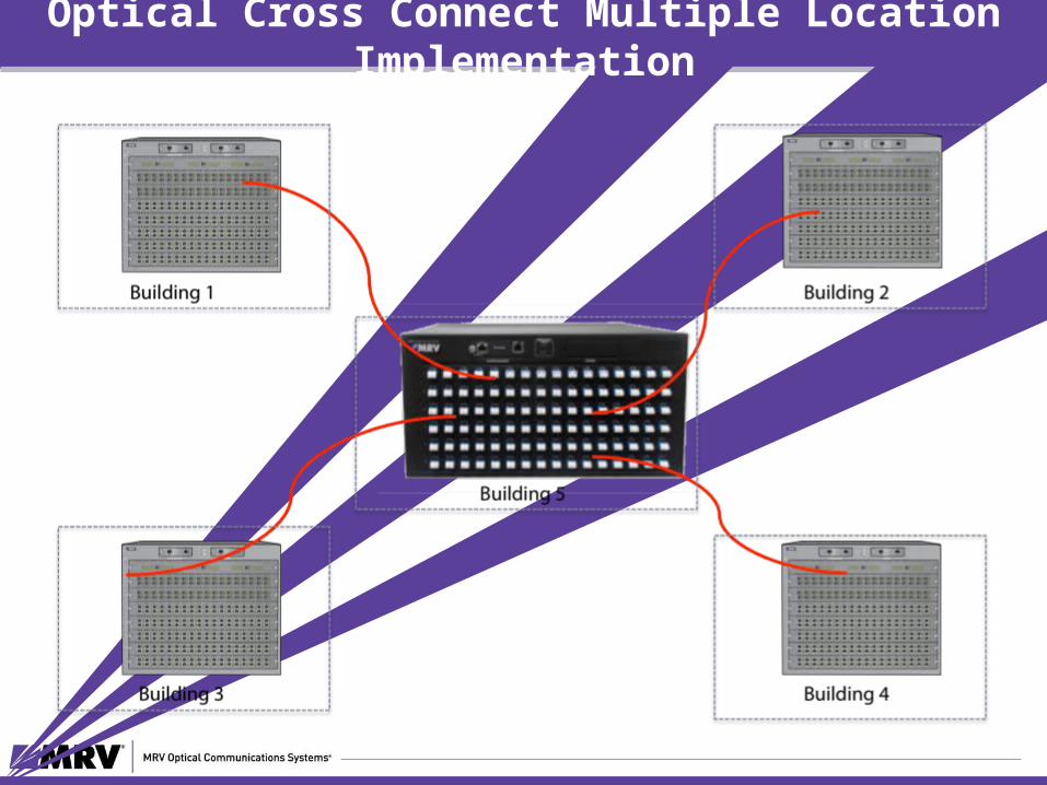
Optical Cross Connect Multiple Location Implementation

Media Cross Connect Management Support
27

MCC Management Flexibility

MCC Management Options
CLI - Command Line Interface– Robust command set – “cisco like” CLI
SNMP – North-bound OSS interface
TCL-Based API– Simplify scripting– Library of pre-determined
scripts
PathFinder GUI– Single chassis applications– Mapping Efficiencies– Graphical representation of
topology– Scaled-down tester interface
Commercial 3rd Party Automation Software– Spirent – Test Center and iTest– QualiSystems – Test Shell– Narra Systems- nFast
29

Telnet, SSH, RS 232 Access– Local and Remote Access
SNMP v1/v2c/v3– Standard MIB support integrates into common network management
systems TFTP and SCP support
– Secure software upgrades and configuration file transfers
Command Line Interface

PathFinder – Mapping

Reduce test time
Increase test accuracy
Increase equipment utilization
Expedite new product releases
Minimize operational and capital expense
Position for test automation
MCC: the cornerstone of test automation
32