Embed Size (px)
Citation preview
MME 345
Lecture 12
The Design of Feeding System3. Feeding calculations 2: Optimizing shape and
placement of feeder
Ref:
[1] P. Beeley, Foundry Technology, Butterworth-Heinemann, 2001
[2] J. Campbell, Castings, Butterworth-Heinemann, 2001
[3] Heine, Loper, Rosenthal, Principles of Metal Casting, Tata McGraw-Hill, 1976
1. Optimizing shape of feeder
2. Optimizing placement of feeder
3. Increasing the efficiency of feeder
Topics to discuss....
1. Optimizing Feeder Shape
The shape of the feeder plays an important part in keeping the metal it contains in
liquid form. So the feeder should be shaped so that it promotes a slow cooling rate.
surface area of the casting relative to volume is important in determining the rate of heat transfer
from the casting.
According to Chvorinov's rule, solidification time of a given shape is proportional to
its modulus , i.e., square of its (V/A) ratio
for a feeder of a given size to have a maximum solidification time,
it must have the smallest surface area
Amongst all shapes, a sphere has the smallest surface area
a spherical feeder head will remain liquid for the longest period of time amongst all shapes
of unit volume
3/24
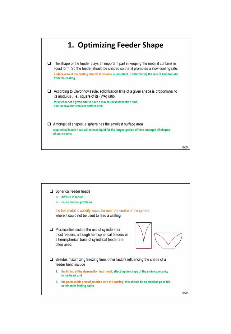
Spherical feeder heads
difficult to mould
cause feeding problems
the last metal to solidify would be near the centre of the sphere,
where it could not be used to feed a casting
Besides maximizing freezing time, other factors influencing the shape of a
feeder head include
1. the timing of the demand for feed metal, affecting the shape of the shrinkage cavity
in the head, and
2. the permissible area of junction with the casting: this should be as small as possible
to minimize fettling costs
Practicalities dictate the use of cylinders for
most feeders, although hemispherical feeders or
a hemispherical base of cylindrical feeder are
often used.
4/24
Now the diameter of a cylindrical feeder depends on too many factors.
But what about its height?
Most authorities and researchers agree that the minimum height of a riser
should be no less than one-half times its diameter and the maximum height should be
no more than one and a half times its diameter.
D = 100 mm H = 50 – 150 mm
This is because of the V/A ratio.
Dimensions outside those limits would make the V/A ratio lower than it is within them.
These limitations apply to both top and side feeders.
1.1 Optimising feeder dimensions
5/24
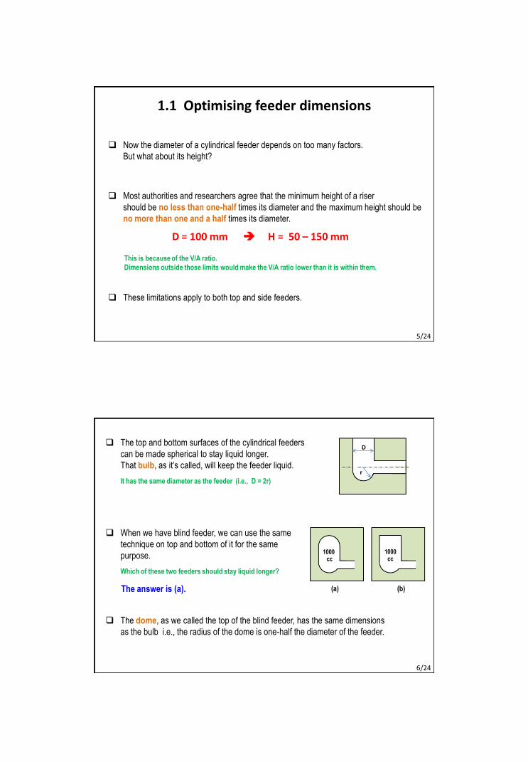
The top and bottom surfaces of the cylindrical feeders
can be made spherical to stay liquid longer.
That bulb, as it’s called, will keep the feeder liquid.
It has the same diameter as the feeder (i.e., D = 2r)
D
r
When we have blind feeder, we can use the same
technique on top and bottom of it for the same
purpose.
Which of these two feeders should stay liquid longer?
1000 cc
1000cc
(a) (b)
The dome, as we called the top of the blind feeder, has the same dimensions
as the bulb i.e., the radius of the dome is one-half the diameter of the feeder.
The answer is (a).
6/24
Like feeder, the neck should stay liquid as long as possible.
That means that the cross-sectional shape of the neck should be circular.
For thin plate castings, a round neck may be impossible.
In that cases, we have to use a neck with a square, or perhaps rectangular, cross-section.
Even though the neck has a circular section, the longer it is for a given diameter,
the more area it will have and the more rapidly it will solidify.
The feeder neck should never exceeds one-half the diameter of the feeder.
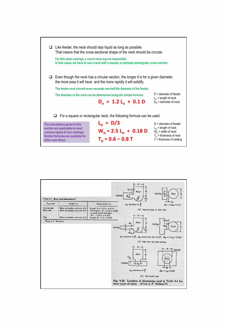
The diameter of the neck can be determined using the simple formula:
Dn = 1.2 Ln + 0.1 D
D = diameter of feeder
Ln = length of neck
Dn = diameter of neck
For a square or rectangular neck, the following formula can be used:
Ln = D/3
Wn = 2.5 Ln + 0.18 D
Tn = 0.6 – 0.8 T
D = diameter of feeder
Ln = length of neck
Wn = width of neck
Tn = thickness of neck
T = thickness of casting
The calculations given in this
section are applicable to most
common types of iron castings.
Similar formulas are available for
other cast alloys.
2. Optimizing Placement of Feeder
In complex castings, the shape is divided into a number of natural zones of feeding,
each centred on a heavy section separated from the remainder of the casting by
more constricted numbers.
Each zone is then fed by a separately calculated feeder
Feeder heads are normally placed in direct contact with the heavier sections
of a casting, since this enables directional solidification to be maintained
throughout freezing.
In normal conditions, there will be a limit to how far feed liquid can be provided
along a flow path.
Up to this distance from the feeder, the casting will be sound.
Beyond this distance, the casting will exhibit porosity.
9/24
For many extended castings feeding range is the limiting factor as appreciable
temperature gradients are needed for feeding and these are difficult to induce in
parallel sections over long distances.
Examples to obtain castings free from
dispersed porosity:
steels :
~ 0.2–0.4 °C gradients/cm (plate)
~ 1.5–2.6 °C/cm (bars)
non-ferrous alloys :
~ 5.5 °C gradients/cm
~ 13 °C gradients/cm
(long freezing range alloys)
• steep temperature gradients against end walls
• shallow gradients adjacent to feeder heads
• isothermal plateau in intermediate regions
• feeding can only take place over very short
distances in such plateau zones and centre
line shrinkage generated in remaining areas temperature distribution in a solidifying steel bar
When a long bar or a plate is cast without a feeder, a certain length of the casting
from each end of the bar/plat is sound.
this results from the directional solidification that developed at the ends because of faster
cooling rate.
This is called the end effect.
When a long bar/plate is cast using a feeder at the centre of the casting,
a certain distance from the feeder (in any direction) the bar/plat is sound.
This is called the feeder effect.
The use of chill provides a powerful influence in extending the feeding range
of heads when placed at intermediate positions of feeders.
the spacing between feeder heads can in this case be more than doubled,
which also greatly increases the casting yield.
11/24
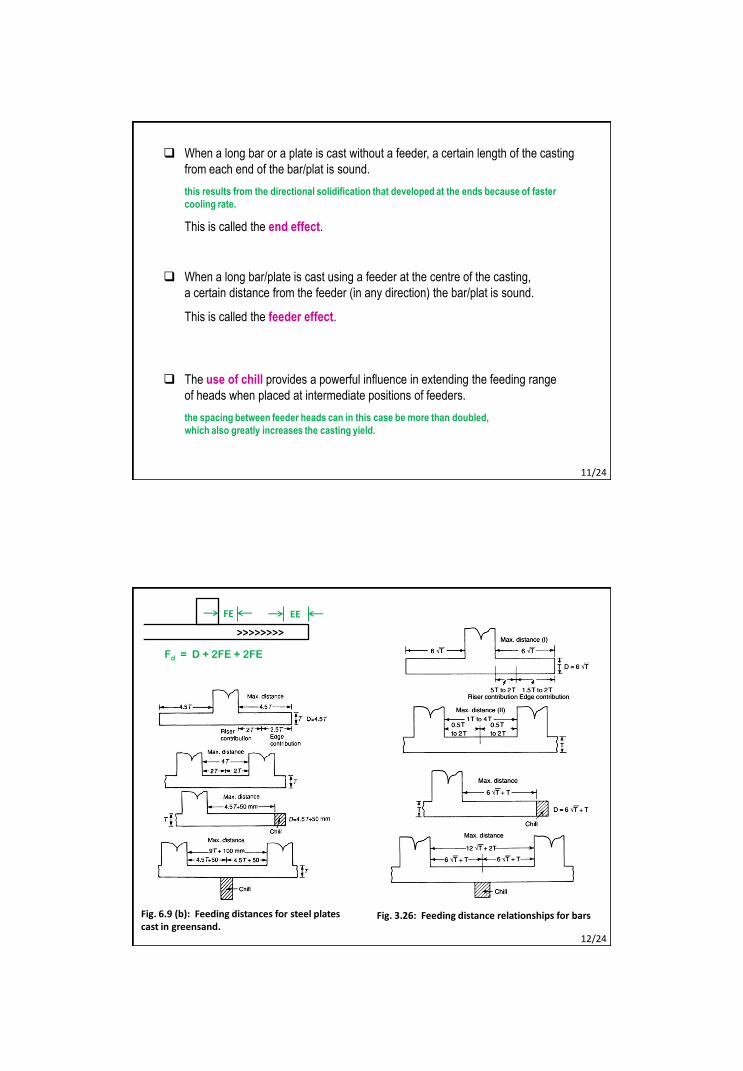
Fig. 6.9 (b): Feeding distances for steel plates cast in greensand.
Fig. 3.26: Feeding distance relationships for bars
12/24
FE EE
>>>>>>>>
Fd = D + 2FE + 2FE
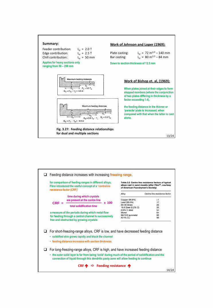
Summary:
Feeder contribution: Ld = 2.0 TEdge contribution: Ld = 2.5 TChill contribution: Ld = 50 mm
Applies for heavy sections only
ranging from 50 – 200 mm
Work of Johnson and Loper (1969):
Plate casting: Ld = 72 m1/2 – 140 mmBar casting: Ld = 80 m1/2 – 84 mm
Down to section thickness of 12.5 mm
Fig. 3.27: Feeding distance relationships for dual and multiple sections
Work of Bishop et. al, (1969):
When plates joined at their edges to form
stepped members (where the conjunction
of two plates differing in thickness by a
factor exceeding 1.4),
the feeding distance in the thinner or
‘parasite’ plate is increased, when
compared with that when the latter is cast
alone.
13/24
Feeding distance increases with increasing freezing range.
time during which crystals
are present at the centre line
total solidification timeCRF = x 100
for comparison of feeding ranges in different alloys,
Flinn introduced the useful concept of a ‘centreline
resistance factor (CRF)’
a measure of the periods during which metal flow
for feeding through a central channel is successively
free and obstructed by growing crystals
CRF Feeding resistance
For short-freezing-range alloys, CRF is low, and have decreased feeding distance
• solidified skin grows rapidly and block the channel
• feeding distance increases with section thickness
For long-freezing-range alloys, CRF is high, and have increased feeding distance
• the outer solid layer is far from being ‘solid’ during much of the period of solidification and the
connection of liquid through this dendritic pasty zone will allow feeding to continue
14/24
3. Increasing Efficiency of Feeder
The efficiency of a feeder head may be defined as the amount of feed metal supplied
to the casting in relation to the total weight of metal initially present in the head.
Efficiency, U = x 100I – F
II = initial volume of metal in head
F = final volume of metal in head
The efficiency of a plain feeder head is very low, since solidification proceeds in the
head at the same time as in the casting.
15/24
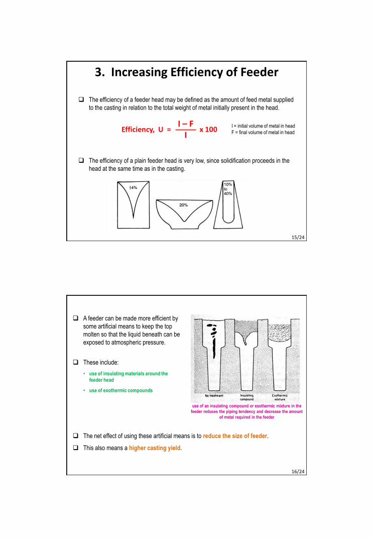
A feeder can be made more efficient by
some artificial means to keep the top
molten so that the liquid beneath can be
exposed to atmospheric pressure.
These include:
• use of insulating materials around the
feeder head
• use of exothermic compounds
The net effect of using these artificial means is to reduce the size of feeder.
This also means a higher casting yield.
use of an insulating compound or exothermic mixture in the
feeder reduces the piping tendency and decrease the amount
of metal required in the feeder
16/24
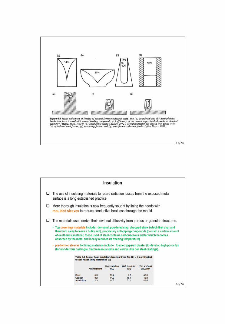
17/24
Insulation
The use of insulating materials to retard radiation losses from the exposed metal
surface is a long established practice.
More thorough insulation is now frequently sought by lining the heads with
moulded sleeves to reduce conductive heat loss through the mould.
The materials used derive their low heat diffusivity from porous or granular structures.
• Top coverings materials include: dry sand, powdered slag, chopped straw (which first char and
then burn away to leave a bulky ash), proprietary anti-piping compounds (contain a certain amount
of exothermic material; those used of steel contains carbonaceous matter which becomes
absorbed by the metal and locally reduces its freezing temperature)
• pre-formed sleeves for lining materials include: foamed gypsum plaster (to develop high porosity)
(for non-ferrous castings), diatomaceous silica and vermiculite (for steel castings).
18/24
Exothermic materials
Considerable heat is generated by exothermic reaction; in some cases molten metal
is also produced.
Common materials used: thermit mixture (fine mixture of aluminium and iron oxide),
powdered charcoal or graphite, rice or oat husk, and refractory powder.
Thermit reactions:
2Al + Fe2O3 = Al2O3 + 2Fe; DH298 = -853 kJ8Al + 3Fe3O4 = 4Al2O3 + 9Fe; DH298 = -3347 kJ
Added in two ways:
1. Material is added on top of feeder to control feeding. Composition must be compatible with
that of the casting.
2. Material is mixed with bonding material and water to mould sleeve for lining feeder head.
The added substance helps delaying exothermic reacting and extend the period during which
heat is generated. This diminishes the danger of contamination, since the exothermic reaction
is confined to the mould wall. The period during which heat is generated is controlled.
19/24
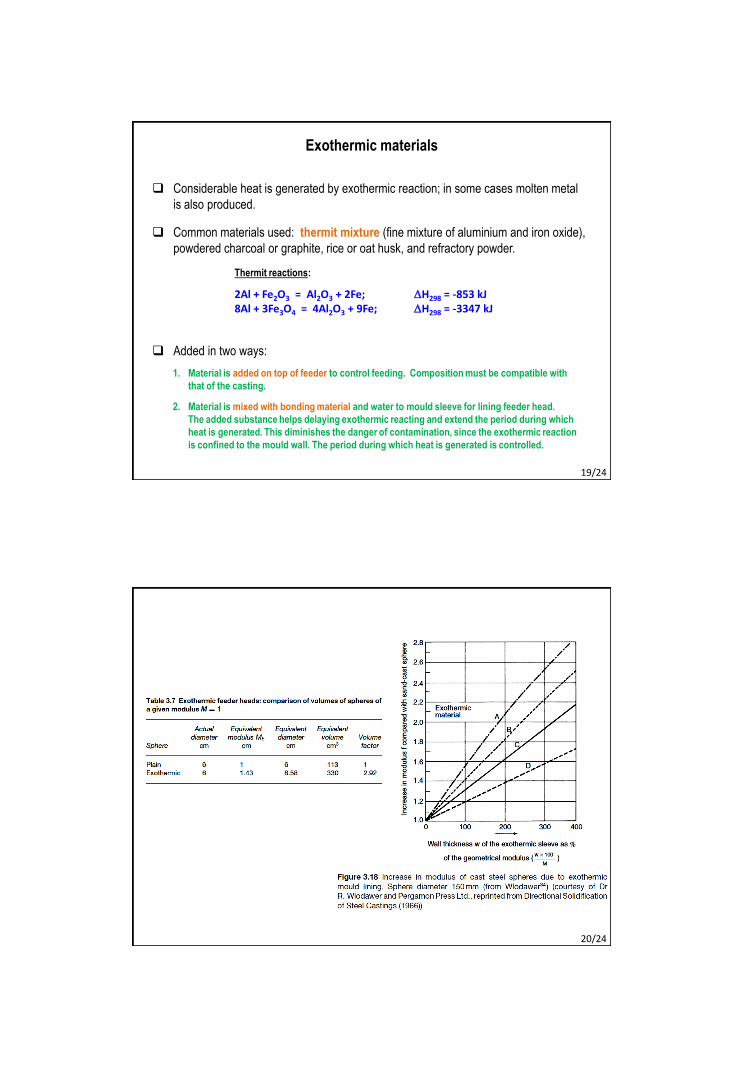
20/24
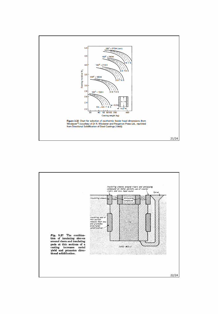
21/24
22/24
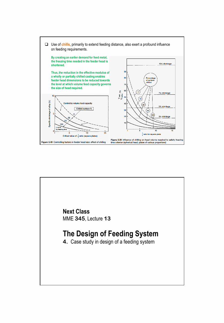
Use of chills, primarily to extend feeding distance, also exert a profound influence
on feeding requirements.
By creating an earlier demand for feed metal,
the freezing time needed in the feeder head is
shortened.
Thus, the reduction in the effective modulus of
a wholly or partially chilled casting enables
feeder head dimensions to be reduced towards
the level at which volume feed capacity governs
the size of head required.
Next ClassMME 345, Lecture 13
The Design of Feeding System4. Case study in design of a feeding system


![WELCOME [teacher.buet.ac.bd]teacher.buet.ac.bd/ziawadud/documents/seraj.pdf · welcome to the presentation on ... typical sheltech organogram of construction management. may 24,](https://img.pdfslide.net/doc/110x75/5a858de47f8b9ad30c8c768a/welcome-to-the-presentation-on-typical-sheltech-organogram-of-construction.jpg)