Embed Size (px)
Citation preview
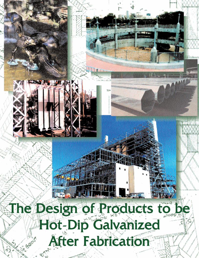
The Design of Products to beHot-DDip Galvanized
After Fabrication
The galvanizing process has existed for more than 250 years and hasbeen a mainstay of North American industry since the 1890s.Galvanizing is used throughout various markets to provide steel withunmatched protection from the ravages of corrosion. A wide range ofsteel products – from nails to highway guardrail to the BrooklynBridge’s suspension wires to NASA’s launch pad sound-suppressionsystem – benefit from galvanizing’s superior corrosion preventionproperties.
Galvanizing’s primary component is zinc. This vital substance is silveryblue-gray in color and makes up an estimated 0.004% of the earth’s crust, ranking 25th in order of abundance. It is essential for the growth and development of almost all life. Between 1.4 and 2.3 gramsof zinc are found in the average adult, and the World HealthOrganization has recommended a daily intake of 15 milligrams.Numerous consumer products, including cold remedies, sunscreens,diaper creams, and nutritional supplements, contain beneficialamounts of zinc, primarily in the form of zinc oxide.
Even though galvanized steel is blue-gray, it also can be “green.” Thezinc and galvanizing industries work to promote sustainable develop-ment by enhancing zinc’s contribution to society and ensuring that itsproduction and use are in harmony with the natural environment andthe needs of society, now and in the future.
Zinc, as it is used in galvanizing, is a healthy metal, completely recycl-able. The energy used to smelt zinc is inversely related to the amountof zinc recycled. Galvanizing delivers incredible value in terms of protect-ing our infrastructure. Less steel is consumed and fewer raw materialsare needed because galvanizing makes steel structures, bridges, roads,and buildings last longer. Over time, galvanizing helps maintain steelfabrications’ structural integrity: galvanized structures are safer.
Additionally, because galvanized steel requires no maintenance fordecades, its use in public construction is an efficient use of our taxes.Selecting galvanized steel for private projects makes a significantcontribution to a company’s profitability.
© 2005 American Galvanizers Association, Inc. The material in this publication has been developed to provide accurate and authoritative information about the design of productsto be hot-dip galvanized after fabrication. This material provides general information only and is not intended as a substitute for competent professional examination and verificationas to suitability and applicability. The publication of the material herein is not intended as a representation or warranty on the part of the American Galvanizers Association, Inc.Anyone using this information assumes all liability arising from such use.
THE DESIGN OF PRODUCTS TO BE
HOT-DIP GALVANIZED AFTER FABRICATION
TABLE OF CONTENTS
Design Considerations ..............................................................................................................................2Communication Among Design Engineer, Fabricator & Galvanizer.......................................................2Materials Suitable for Galvanizing...........................................................................................................3Combining Different Materials and Surfaces...........................................................................................4Welding Procedures & Welding Flux Removal........................................................................................5Mechanical Properties of Galvanized Steel..............................................................................................6
Strain-age Embrittlement ....................................................................................................................6Hydrogen Embrittlement ....................................................................................................................7
Size & Shape.............................................................................................................................................8Allowing for Proper Drainage ..................................................................................................................9Tubular Fabrications & Hollow Structurals .............................................................................................9
Cleaning ..............................................................................................................................................9Venting ..............................................................................................................................................10Handrail ............................................................................................................................................11Rectangular Tube Truss ...................................................................................................................12Pipe Truss .........................................................................................................................................12Pipe Columns & Girders, Street Light & Transmission Poles ........................................................13Box Sections ....................................................................................................................................13Tapered-Signal Arm .........................................................................................................................14Designing for Proper Venting & Draining of Enclosed & Semi-Enclosed Products.......................14
Minimizing Distortion ............................................................................................................................15Precautions for Overlapping & Contacting Surfaces .............................................................................16Castings...................................................................................................................................................17Threaded Parts ........................................................................................................................................18Moving Parts...........................................................................................................................................19Marking for Identification ......................................................................................................................20Related Specifications.............................................................................................................................21
DESIGN CONSIDERATIONS
Protection against corrosion begins at the drawing board. No matter what corrosion protection system isspecified, it must be factored into the product’s design.
Once the decision has been made to hot-dip galvanize steel for maximum corrosion prevention, the designengineer should ensure that the pieces can be suitably fabricated for highest-quality galvanizing.
Certain rules apply when designing components for galvanizing. These rules are readily followed and, inmost cases, are simply those that good practice would dictate to ensure maximum corrosion protection.
Adopting the following design practices, along with those listed in ASTM A 385, Practice for Providing HighQuality Zinc Coatings (Hot-Dip), will produce optimum quality galvanized steel, reduce coating costs, and assistwith timely product processing.
COMMUNICATION AMONG DESIGNENGINEER, FABRICATOR & GALVANIZER
Throughout the process, from designing to speci-fication to galvanizing, it is highly beneficial for thedesigner, fabricator, and galvanizer to communicate.This ongoing communication can maximize opportu-nities for on-time project delivery and superior quali-ty galvanized steel.
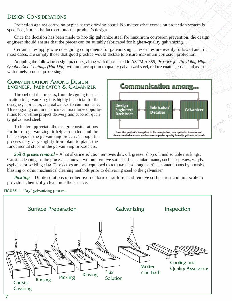
To better appreciate the design considerationsfor hot-dip galvanizing, it helps to understand thebasic steps of the galvanizing process. Though theprocess may vary slightly from plant to plant, thefundamental steps in the galvanizing process are:
Soil & grease removal − A hot alkaline solution removes dirt, oil, grease, shop oil, and soluble markings.Caustic cleaning, as the process is known, will not remove some surface contaminants, such as epoxies, vinyls,asphalts, or welding slag. Fabricators are best equipped to remove these tough surface contaminants by abrasiveblasting or other mechanical cleaning methods prior to delivering steel to the galvanizer.
Pickling − Dilute solutions of either hydrochloric or sulfuric acid remove surface rust and mill scale toprovide a chemically clean metallic surface.
Surface Preparation Galvanizing Inspection
CausticCleaning
Rinsing Pickling Rinsing FluxSolution
MoltenZinc Bath
Cooling andQuality Assurance
2
FIGURE 1: “Dry“ galvanizing process
Fluxing − Steel is immersed in liquid flux (usually a zinc ammonium chloride solution) to remove oxidesand to prevent oxidation prior to dipping into the molten zinc bath. In the “dry” galvanizing process (Figure 1),the item is separately dipped in a liquid flux bath, removed, allowed to dry, and then galvanized. In the “wet”galvanizing process, the flux floats atop the molten zinc and the item passes through the flux immediately priorto galvanizing. Either method effectively promotes the metallurgical bond between zinc and steel.
Galvanizing − The article is immersed in a bath of molten zinc at between 815-850 F (435-455 C). Duringgalvanizing, the zinc metallurgically bonds to the steel, creating a series of highly abrasion-resistant zinc-ironalloy layers, topped by a layer of impact-resistant pure zinc.
Finishing − After the steel is withdrawn from the galvanizing bath, excess zinc is removed by draining,vibrating or - for small items - centrifuging. The galvanized item is then air-cooled or quenched in liquid.
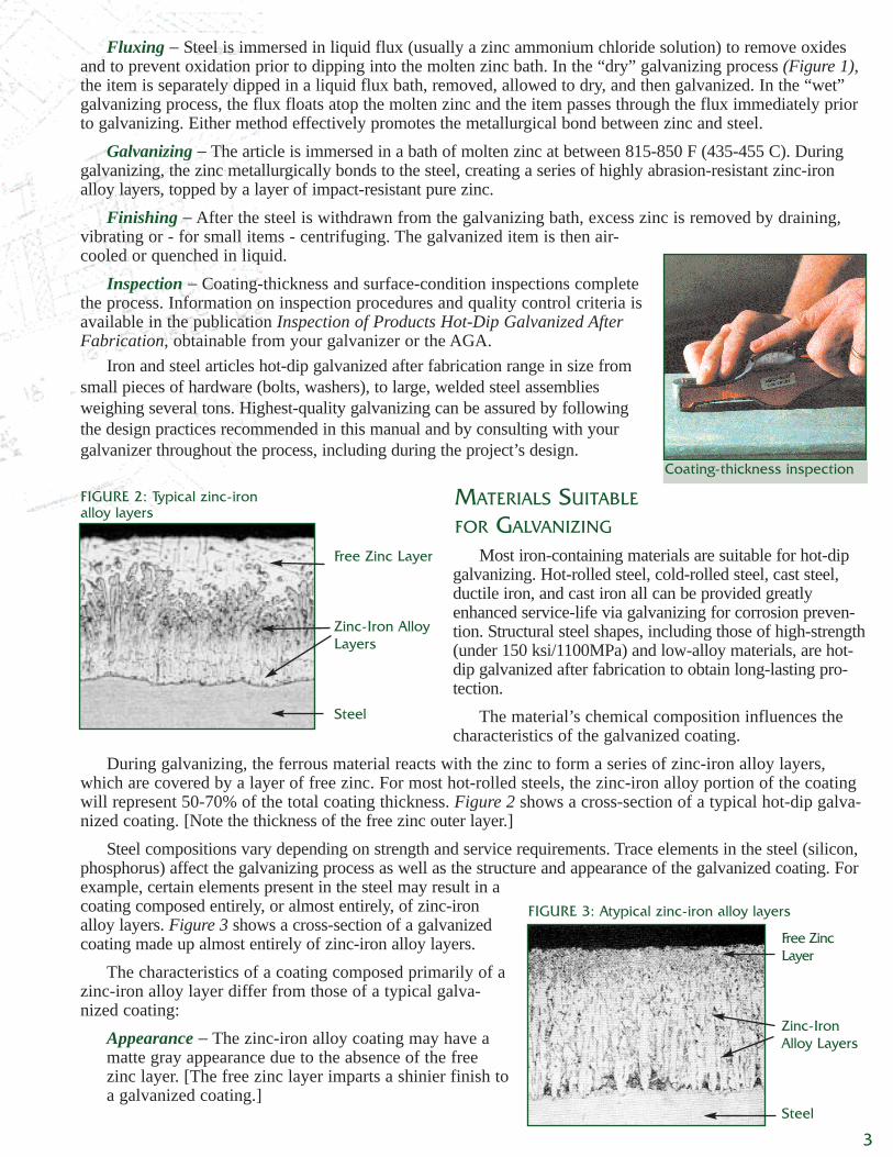
Inspection − Coating-thickness and surface-condition inspections completethe process. Information on inspection procedures and quality control criteria isavailable in the publication Inspection of Products Hot-Dip Galvanized AfterFabrication, obtainable from your galvanizer or the AGA.
Iron and steel articles hot-dip galvanized after fabrication range in size fromsmall pieces of hardware (bolts, washers), to large, welded steel assembliesweighing several tons. Highest-quality galvanizing can be assured by followingthe design practices recommended in this manual and by consulting with yourgalvanizer throughout the process, including during the project’s design.
MATERIALS SUITABLE
FOR GALVANIZING
Most iron-containing materials are suitable for hot-dipgalvanizing. Hot-rolled steel, cold-rolled steel, cast steel,ductile iron, and cast iron all can be provided greatlyenhanced service-life via galvanizing for corrosion preven-tion. Structural steel shapes, including those of high-strength(under 150 ksi/1100MPa) and low-alloy materials, are hot-dip galvanized after fabrication to obtain long-lasting pro-tection.
The material’s chemical composition influences thecharacteristics of the galvanized coating.
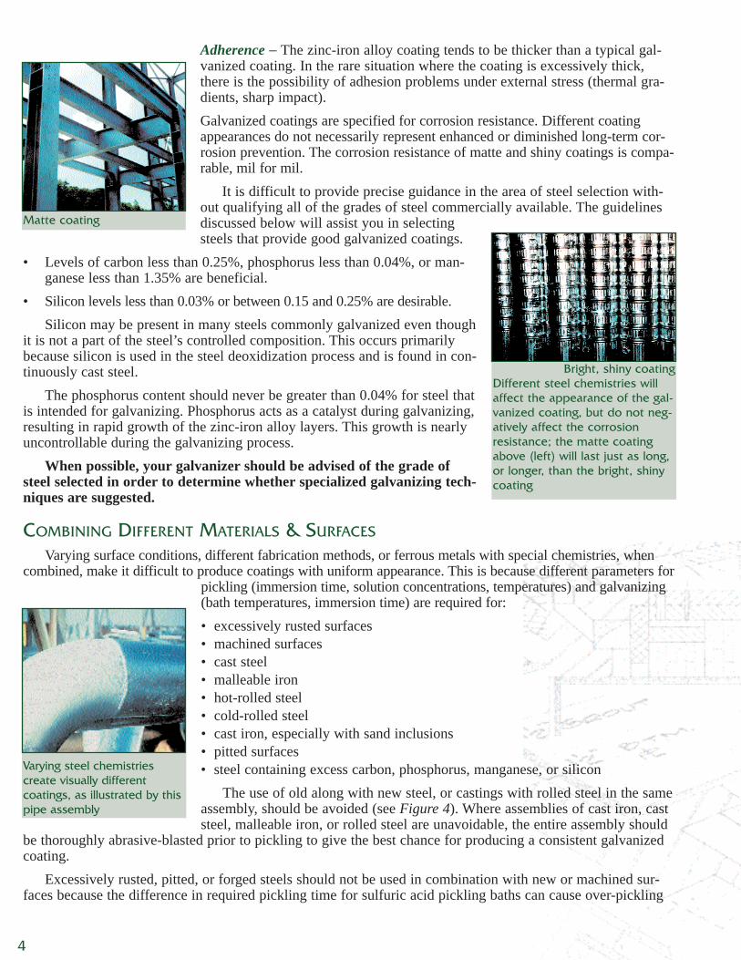
During galvanizing, the ferrous material reacts with the zinc to form a series of zinc-iron alloy layers,which are covered by a layer of free zinc. For most hot-rolled steels, the zinc-iron alloy portion of the coatingwill represent 50-70% of the total coating thickness. Figure 2 shows a cross-section of a typical hot-dip galva-nized coating. [Note the thickness of the free zinc outer layer.]
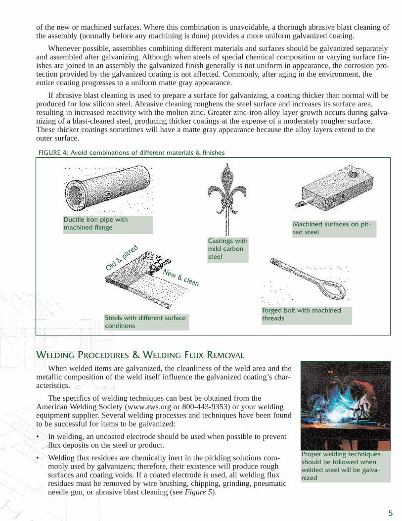
Steel compositions vary depending on strength and service requirements. Trace elements in the steel (silicon,phosphorus) affect the galvanizing process as well as the structure and appearance of the galvanized coating. Forexample, certain elements present in the steel may result in acoating composed entirely, or almost entirely, of zinc-ironalloy layers. Figure 3 shows a cross-section of a galvanizedcoating made up almost entirely of zinc-iron alloy layers.
The characteristics of a coating composed primarily of azinc-iron alloy layer differ from those of a typical galva-nized coating:
Appearance − The zinc-iron alloy coating may have amatte gray appearance due to the absence of the freezinc layer. [The free zinc layer imparts a shinier finish toa galvanized coating.]
Coating-thickness inspection
FIGURE 2: Typical zinc-iron alloy layers
Free Zinc Layer
Zinc-Iron AlloyLayers
Steel
FIGURE 3: Atypical zinc-iron alloy layers
Free ZincLayer
Zinc-IronAlloy Layers
Steel
3
Adherence − The zinc-iron alloy coating tends to be thicker than a typical gal-vanized coating. In the rare situation where the coating is excessively thick,there is the possibility of adhesion problems under external stress (thermal gra-dients, sharp impact).Galvanized coatings are specified for corrosion resistance. Different coatingappearances do not necessarily represent enhanced or diminished long-term cor-rosion prevention. The corrosion resistance of matte and shiny coatings is compa-rable, mil for mil.
It is difficult to provide precise guidance in the area of steel selection with-out qualifying all of the grades of steel commercially available. The guidelinesdiscussed below will assist you in selectingsteels that provide good galvanized coatings.
• Levels of carbon less than 0.25%, phosphorus less than 0.04%, or man-ganese less than 1.35% are beneficial.
• Silicon levels less than 0.03% or between 0.15 and 0.25% are desirable.Silicon may be present in many steels commonly galvanized even though
it is not a part of the steel’s controlled composition. This occurs primarilybecause silicon is used in the steel deoxidization process and is found in con-tinuously cast steel.
The phosphorus content should never be greater than 0.04% for steel thatis intended for galvanizing. Phosphorus acts as a catalyst during galvanizing,resulting in rapid growth of the zinc-iron alloy layers. This growth is nearlyuncontrollable during the galvanizing process.
When possible, your galvanizer should be advised of the grade ofsteel selected in order to determine whether specialized galvanizing tech-niques are suggested.
COMBINING DIFFERENT MATERIALS & SURFACES
Varying surface conditions, different fabrication methods, or ferrous metals with special chemistries, whencombined, make it difficult to produce coatings with uniform appearance. This is because different parameters for
pickling (immersion time, solution concentrations, temperatures) and galvanizing(bath temperatures, immersion time) are required for:• excessively rusted surfaces• machined surfaces• cast steel• malleable iron• hot-rolled steel• cold-rolled steel• cast iron, especially with sand inclusions• pitted surfaces• steel containing excess carbon, phosphorus, manganese, or silicon
The use of old along with new steel, or castings with rolled steel in the sameassembly, should be avoided (see Figure 4). Where assemblies of cast iron, caststeel, malleable iron, or rolled steel are unavoidable, the entire assembly should
be thoroughly abrasive-blasted prior to pickling to give the best chance for producing a consistent galvanizedcoating.
Excessively rusted, pitted, or forged steels should not be used in combination with new or machined sur-faces because the difference in required pickling time for sulfuric acid pickling baths can cause over-pickling
Matte coating
Bright, shiny coatingDifferent steel chemistries willaffect the appearance of the gal-vanized coating, but do not neg-atively affect the corrosionresistance; the matte coatingabove (left) will last just as long,or longer, than the bright, shinycoating
Varying steel chemistries create visually different coatings, as illustrated by thispipe assembly
4
of the new or machined surfaces. Where this combination is unavoidable, a thorough abrasive blast cleaning ofthe assembly (normally before any machining is done) provides a more uniform galvanized coating.
Whenever possible, assemblies combining different materials and surfaces should be galvanized separatelyand assembled after galvanizing. Although when steels of special chemical composition or varying surface fin-ishes are joined in an assembly the galvanized finish generally is not uniform in appearance, the corrosion pro-tection provided by the galvanized coating is not affected. Commonly, after aging in the environment, theentire coating progresses to a uniform matte gray appearance.
If abrasive blast cleaning is used to prepare a surface for galvanizing, a coating thicker than normal will beproduced for low silicon steel. Abrasive cleaning roughens the steel surface and increases its surface area,resulting in increased reactivity with the molten zinc. Greater zinc-iron alloy layer growth occurs during galva-nizing of a blast-cleaned steel, producing thicker coatings at the expense of a moderately rougher surface.These thicker coatings sometimes will have a matte gray appearance because the alloy layers extend to theouter surface.
WELDING PROCEDURES & WELDING FLUX REMOVAL
When welded items are galvanized, the cleanliness of the weld area and themetallic composition of the weld itself influence the galvanized coating’s char-acteristics.
The specifics of welding techniques can best be obtained from theAmerican Welding Society (www.aws.org or 800-443-9353) or your weldingequipment supplier. Several welding processes and techniques have been foundto be successful for items to be galvanized:• In welding, an uncoated electrode should be used when possible to prevent
flux deposits on the steel or product.• Welding flux residues are chemically inert in the pickling solutions com-
monly used by galvanizers; therefore, their existence will produce roughsurfaces and coating voids. If a coated electrode is used, all welding fluxresidues must be removed by wire brushing, chipping, grinding, pneumaticneedle gun, or abrasive blast cleaning (see Figure 5).
Old & pitted
New & clean
Ductile iron pipe withmachined flange
Forged bolt with machinedthreads
Castings withmild carbonsteel
Steels with different surfaceconditions
Machined surfaces on pit-ted steel
FIGURE 4: Avoid combinations of different materials & finishes
Proper welding techniquesshould be followed whenwelded steel will be galva-nized
5
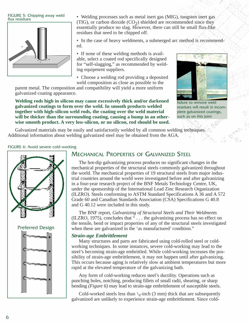
• Welding processes such as metal inert gas (MIG), tungsten inert gas(TIG), or carbon dioxide (CO2) shielded are recommended since theyessentially produce no slag. However, there can still be small flux-likeresidues that need to be chipped off.• In the case of heavy weldments, a submerged arc method is recommend-ed.• If none of these welding methods is avail-able, select a coated rod specifically designedfor “self-slagging,” as recommended by weld-ing equipment suppliers.• Choose a welding rod providing a depositedweld composition as close as possible to the
parent metal. The composition and compatibility will yield a more uniformgalvanized coating appearance.Welding rods high in silicon may cause excessively thick and/or darkenedgalvanized coatings to form over the weld. In smooth products weldedtogether with high-silicon weld rods, the coating over the weld materialwill be thicker than the surrounding coating, causing a bump in an other-wise smooth product. A very low-silicon, or no silicon, rod should be used.Galvanized materials may be easily and satisfactorily welded by all common welding techniques.
Additional information about welding galvanized steel may be obtained from the AGA.
MECHANICAL PROPERTIES OF GALVANIZED STEEL
The hot-dip galvanizing process produces no significant changes in themechanical properties of the structural steels commonly galvanized throughoutthe world. The mechanical properties of 19 structural steels from major indus-trial countries around the world were investigated before and after galvanizingin a four-year research project of the BNF Metals Technology Centre, UK,under the sponsorship of the International Lead Zinc Research Organization(ILZRO). Steels conforming to ASTM Standard Specifications A 36 and A 572Grade 60 and Canadian Standards Association (CSA) Specifications G 40.8and G 40.12 were included in this study.
The BNF report, Galvanizing of Structural Steels and Their Weldments(ILZRO, 1975), concludes that “ . . . the galvanizing process has no effect onthe tensile, bend or impact properties of any of the structural steels investigatedwhen these are galvanized in the ‘as manufactured’ condition.”Strain-age Embrittlement
Many structures and parts are fabricated using cold-rolled steel or cold-working techniques. In some instances, severe cold-working may lead to thesteel’s becoming strain-age embrittled. While cold-working increases the pos-sibility of strain-age embrittlement, it may not happen until after galvanizing.This occurs because aging is relatively slow at ambient temperatures but morerapid at the elevated temperature of the galvanizing bath.
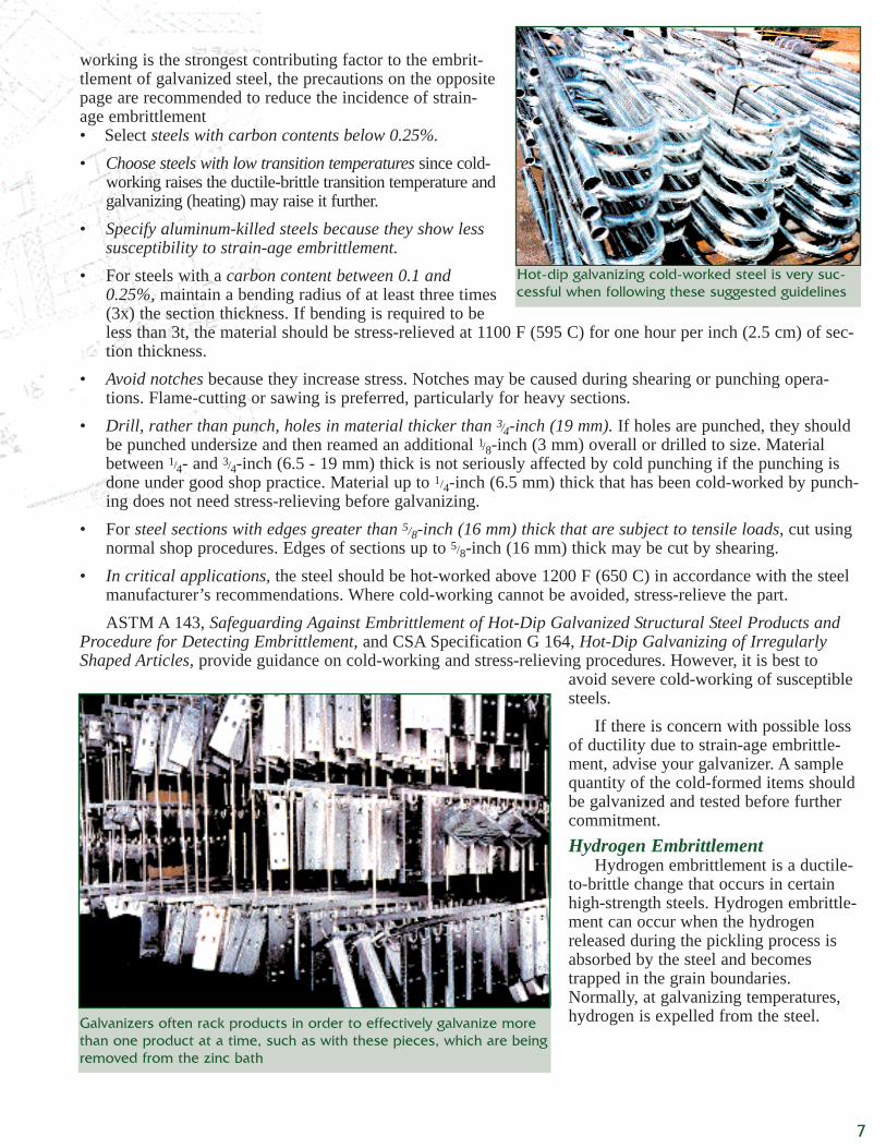
Any form of cold-working reduces steel’s ductility. Operations such aspunching holes, notching, producing fillets of small radii, shearing, or sharpbending (Figure 6) may lead to strain-age embrittlement of susceptible steels.
Cold-worked steels less than 1/8-inch (3 mm) thick that are subsequentlygalvanized are unlikely to experience strain-age embrittlement. Since cold-
FIGURE 5: Chipping away weldflux residues
Failure to remove weldresidues will result in incom-plete galvanized coatings,such as on this joint
Preferred Design
6
FIGURE 6: Avoid severe cold-working
working is the strongest contributing factor to the embrit-tlement of galvanized steel, the precautions on the oppositepage are recommended to reduce the incidence of strain-age embrittlement• Select steels with carbon contents below 0.25%.• Choose steels with low transition temperatures since cold-
working raises the ductile-brittle transition temperature andgalvanizing (heating) may raise it further.
• Specify aluminum-killed steels because they show lesssusceptibility to strain-age embrittlement.
• For steels with a carbon content between 0.1 and0.25%, maintain a bending radius of at least three times(3x) the section thickness. If bending is required to beless than 3t, the material should be stress-relieved at 1100 F (595 C) for one hour per inch (2.5 cm) of sec-tion thickness.
• Avoid notches because they increase stress. Notches may be caused during shearing or punching opera-tions. Flame-cutting or sawing is preferred, particularly for heavy sections.
• Drill, rather than punch, holes in material thicker than 3/4-inch (19 mm). If holes are punched, they shouldbe punched undersize and then reamed an additional 1/8-inch (3 mm) overall or drilled to size. Materialbetween 1/4- and 3/4-inch (6.5 - 19 mm) thick is not seriously affected by cold punching if the punching isdone under good shop practice. Material up to 1/4-inch (6.5 mm) thick that has been cold-worked by punch-ing does not need stress-relieving before galvanizing.
• For steel sections with edges greater than 5/8-inch (16 mm) thick that are subject to tensile loads, cut usingnormal shop procedures. Edges of sections up to 5/8-inch (16 mm) thick may be cut by shearing.
• In critical applications, the steel should be hot-worked above 1200 F (650 C) in accordance with the steelmanufacturer’s recommendations. Where cold-working cannot be avoided, stress-relieve the part.ASTM A 143, Safeguarding Against Embrittlement of Hot-Dip Galvanized Structural Steel Products and
Procedure for Detecting Embrittlement, and CSA Specification G 164, Hot-Dip Galvanizing of IrregularlyShaped Articles, provide guidance on cold-working and stress-relieving procedures. However, it is best to
avoid severe cold-working of susceptiblesteels.
If there is concern with possible lossof ductility due to strain-age embrittle-ment, advise your galvanizer. A samplequantity of the cold-formed items shouldbe galvanized and tested before furthercommitment.Hydrogen Embrittlement
Hydrogen embrittlement is a ductile-to-brittle change that occurs in certainhigh-strength steels. Hydrogen embrittle-ment can occur when the hydrogenreleased during the pickling process isabsorbed by the steel and becomestrapped in the grain boundaries.Normally, at galvanizing temperatures,hydrogen is expelled from the steel.Galvanizers often rack products in order to effectively galvanize more
than one product at a time, such as with these pieces, which are beingremoved from the zinc bath
Hot-dip galvanizing cold-worked steel is very suc-cessful when following these suggested guidelines
7
Although hydrogen embrittlement is uncommon, precau-tions should be taken to avoid it, particularly if the steelinvolved has an ultimate tensile strength exceeding 150,000psi (1050 MPa). If high-strength steels are to be processed,grit-blasting instead of acid-pickling is recommended inorder to minimize the introduction of gaseous hydrogen dur-ing the pickling process.
SIZE & SHAPE
With the increase in the sizes and capacities of galvanizingkettles, facilities can accommodate fabrications in a signifi-
cant range of sizes and shapes. Galvanizing kettles up to 42 feet (13 m) in length are available in most indus-trial areas, and kettles in the range of 50, 60 and 80 feet (15, 19 and 25 m) in length are available throughoutNorth America.
Almost any component can be galvanized by designing and fabricating in modules suitable for the avail-able galvanizing facilities. It is wise to verify kettle constraints with your galvanizer at an early stage. (Kettledimensions and phone numbers of member galvanizers are available through the AGA.)
Large structures are galvanized by designing in modules or sub-units that are assembled by field-welding orbolting after galvanizing. Modular design techniques often produce economies in manufacturing and assemblybecause they simplify handling and transportation.
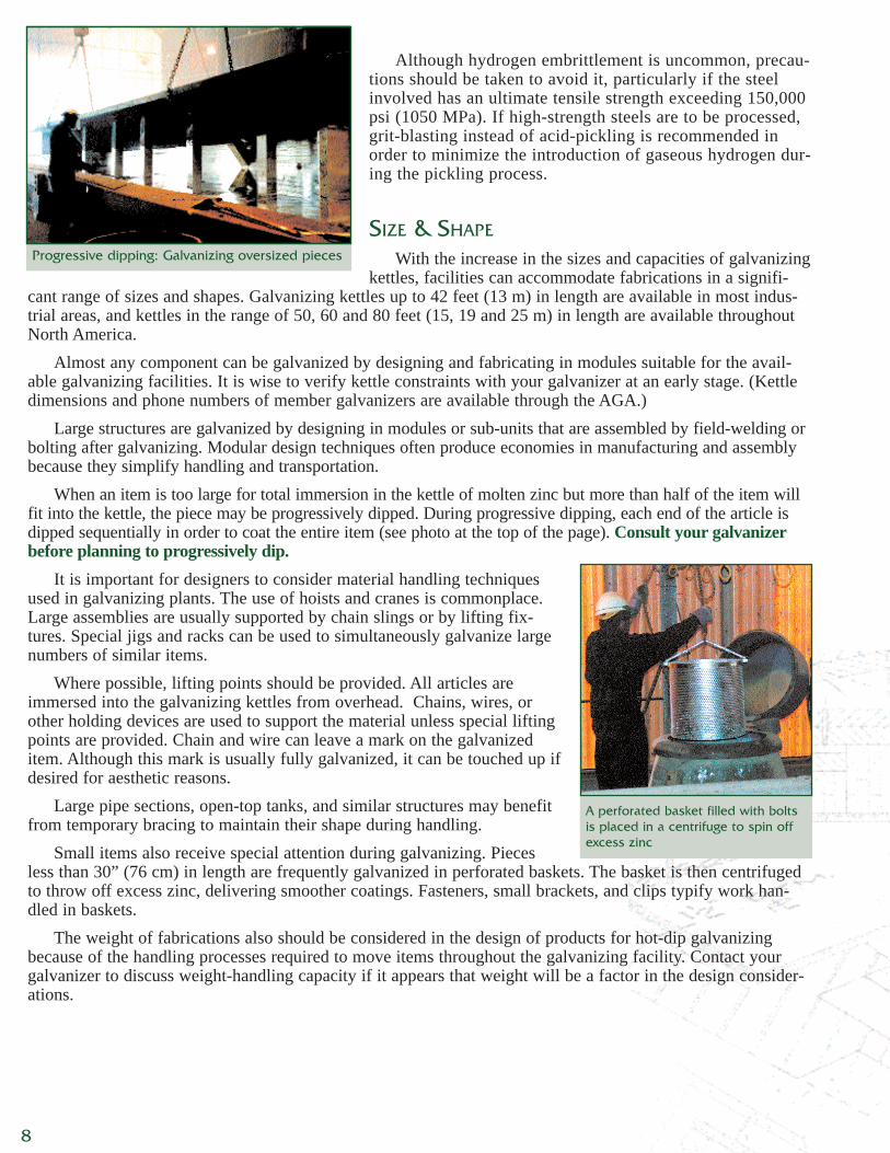
When an item is too large for total immersion in the kettle of molten zinc but more than half of the item willfit into the kettle, the piece may be progressively dipped. During progressive dipping, each end of the article isdipped sequentially in order to coat the entire item (see photo at the top of the page). Consult your galvanizerbefore planning to progressively dip.
It is important for designers to consider material handling techniquesused in galvanizing plants. The use of hoists and cranes is commonplace.Large assemblies are usually supported by chain slings or by lifting fix-tures. Special jigs and racks can be used to simultaneously galvanize largenumbers of similar items.
Where possible, lifting points should be provided. All articles areimmersed into the galvanizing kettles from overhead. Chains, wires, orother holding devices are used to support the material unless special liftingpoints are provided. Chain and wire can leave a mark on the galvanizeditem. Although this mark is usually fully galvanized, it can be touched up ifdesired for aesthetic reasons.
Large pipe sections, open-top tanks, and similar structures may benefitfrom temporary bracing to maintain their shape during handling.
Small items also receive special attention during galvanizing. Piecesless than 30” (76 cm) in length are frequently galvanized in perforated baskets. The basket is then centrifugedto throw off excess zinc, delivering smoother coatings. Fasteners, small brackets, and clips typify work han-dled in baskets.
The weight of fabrications also should be considered in the design of products for hot-dip galvanizingbecause of the handling processes required to move items throughout the galvanizing facility. Contact yourgalvanizer to discuss weight-handling capacity if it appears that weight will be a factor in the design consider-ations.
Progressive dipping: Galvanizing oversized pieces
A perforated basket filled with boltsis placed in a centrifuge to spin offexcess zinc
8
ALLOWING FOR PROPER DRAINAGE
For effective galvanizing, cleaning solutions and molten zinc must flowwithout undue resistance into, over, through, and out of the fabricated article.
Failure to provide for this free, unimpeded flow can result in complicationsfor the galvanizer and the customer. Improper drainage design results in poorappearance, bare spots, and excessive build-up of zinc. All of these are unnec-essary and costly. Again, communication throughout the project is key.
Where gusset plates are used, generouslycropped corners provide for free drainage. Whencropping gusset plates is not possible, holes atleast 1/2-inch (13 mm) in diameter must beplaced in the plates as close to the corners as possible (see Figure 7).
To ensure unimpeded flow of solutions, all stiffeners, gussets, and bracingshould be cropped a minimum of 3/4-inch (19 mm) (see Figure 8).
Provide holes at least 1/2-inch (13 mm) in diameter in end-plates on rolled steelshapes to allow molten zinc access during immersion in the galvanizing bath anddrainage during withdrawal.
Alternatively, holes at least 1/2-inch (13 mm) in diameter can be placed in theweb within 1/4-inch (6 mm) of the end-plate. To facilitate drainage, end-platesshould have holes placed as close to interior corners as possible (see Figure 9).
TUBULAR FABRICATIONS & HOLLOW STRUCTURALS
Tubular assemblies (handrails, pipe columns, pipe girders, street light poles, transmission poles, pipe truss-es, sign bridges) are commonly galvanized because corrosion protection is afforded to the interior and exteriorof the product. To provide an optimal galvanized coating, hollow products require proper cleaning and draining.Cleaning
As with all steel, pipe and other hollow materials must be thoroughly cleaned before the molten zinc willmetallurgically bond with the steel. Pipe can present two specialcleaning challenges.
First, the mill coating (varnish, lacquer, and similar materials)applied by pipe manufacturers requires extra time and effort toremove at the galvanizing plant. Some galvanizers do not havethe capability to remove this coating. Some organic mill coatingformulations, both foreign and domestic, are extremely difficultto remove with common cleaning solutions, so blasting may berequired. Ordering uncoated pipe avoids costly attempts toremove these mill coatings. In some cases, it may be more costeffective to substitute tube for pipe.
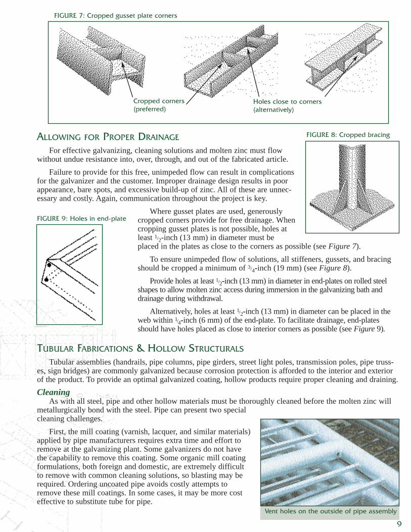
FIGURE 7: Cropped gusset plate corners
Cropped corners(preferred)
Holes close to corners(alternatively)
FIGURE 8: Cropped bracing
FIGURE 9: Holes in end-plate
Vent holes on the outside of pipe assembly
9
Second, welding around mill coatings burns and carbonizes the varnishin the surrounding areas and cannot be removed by the normal cleaningprocess at a galvanizer. This soot must be removed by blasting or othermechanical cleaning methods prior to delivering steel to the galvanizingfacility.Venting
The primary reason for vent and drain holes is to allow air to be evacu-ated, permitting the object to be completely immersed into cleaning solu-tions and molten zinc. Proper sizing and location make it safer to galvanizeand provide the optimal finish. The secondary reason is to prevent damageto the parts. Any pickling solutions or rinse waters that might be trapped ina blind or closed joining connection will be converted to superheated steamor gas and can develop a pressure of up to 3600 psi (1100 MPa) whenimmersed in molten zinc. Not only is there risk of damage to the fabricationbeing galvanized, but there also is risk of serioushazard to galvanizing personnel and equipment.
Air and frothy fluxes must be allowed to flow upward and completely out.Cleaning solutions and molten zinc must be allowed to flow in and completely wetthe surfaces. Proper galvanizing results when the inside and outside of a product arecompletely cleaned and zinc-coated.
The structure must be lowered into the solution without trapping any air, thenraised from the bath without trapping any solution. Consequently, ample passage-ways allowing unimpeded flow into and out of the part must be designed intoassemblies.
Because items to be galvanized are immersed and withdrawn at an angle, thevent holes should be located at the highest point and drain holes at the lowest.
All sections of fabricated pipe-work should be interconnected with full open-teeor miter joints. Each enclosed section must be provided with a vent hole at eachend.
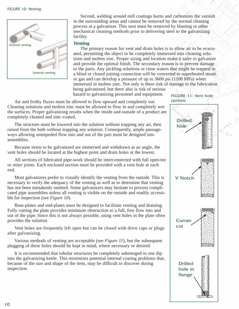
Most galvanizers prefer to visually identify the venting from the outside. This isnecessary to verify the adequacy of the venting as well as to determine that ventinghas not been mistakenly omitted. Some galvanizers may hesitate to process compli-cated pipe assemblies unless all venting is visible on the outside and readily accessi-ble for inspection (see Figure 10).
Base-plates and end-plates must be designed to facilitate venting and draining.Fully cutting the plate provides minimum obstruction to a full, free flow into andout of the pipe. Since this is not always possible, using vent holes in the plate oftenprovides the solution.
Vent holes are frequently left open but can be closed with drive caps or plugsafter galvanizing.
Various methods of venting are acceptable (see Figure 11), but the subsequentplugging of these holes should be kept in mind, where necessary or desired.
It is recommended that tubular structures be completely submerged in one dipinto the galvanizing kettle. This minimizes potential internal coating problems that,because of the size and shape of the item, may be difficult to discover duringinspection.
FIGURE 10: Venting
Internal venting
External venting
FIGURE 11: Vent holeoptions
Drilledhole
V Notch
Cornercut
Drilledhole inflange
10
1
1
1
2
2
3
3
4
2
2
2
4
5
5
2
1
1
Vent holes should be visible on the outside of any pipe assembly to provide internal vent verification
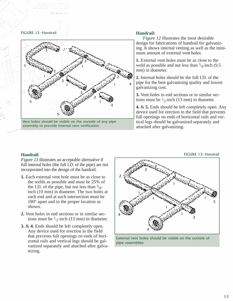
Handrail:Figure 12 illustrates the most desirable
design for fabrications of handrail for galvaniz-ing. It shows internal venting as well as the mini-mum amount of external vent holes.1. External vent holes must be as close to theweld as possible and not less than 3/8-inch (9.5mm) in diameter.2. Internal holes should be the full I.D. of thepipe for the best galvanizing quality and lowestgalvanizing cost.3. Vent holes in end sections or in similar sec-tions must be 1/2-inch (13 mm) in diameter.4. & 5. Ends should be left completely open. Anydevice used for erection in the field that preventsfull openings on ends of horizontal rails and ver-tical legs should be galvanized separately andattached after galvanizing.
FIGURE 12: Handrail
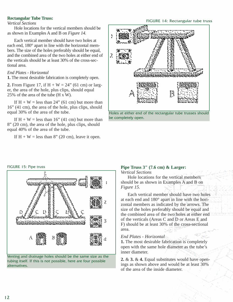
Handrail:Figure 13 illustrates an acceptable alternative iffull internal holes (the full I.D. of the pipe) are notincorporated into the design of the handrail.1. Each external vent hole must be as close to
the welds as possible and must be 25% ofthe I.D. of the pipe, but not less than 3/8-inch (10 mm) in diameter. The two holes ateach end and at each intersection must be180° apart and in the proper location asshown.
2. Vent holes in end sections or in similar sec-tions must be 1/2-inch (13 mm) in diameter.
3. & 4. Ends should be left completely open.Any device used for erection in the fieldthat prevents full openings on ends of hori-zontal rails and vertical legs should be gal-vanized separately and attached after galva-nizing.
External vent holes should be visible on the outside ofpipe assemblies
FIGURE 13: Handrail
1
1
1
2
3
3
4
4
1
2
1
1
11
Rectangular Tube Truss:Vertical Sections
Hole locations for the vertical members should beas shown in Examples A and B on Figure 14.
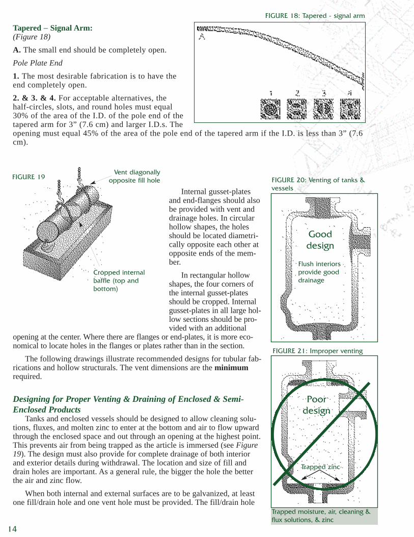
Each vertical member should have two holes ateach end, 180° apart in line with the horizontal mem-bers. The size of the holes preferably should be equal,and the combined area of the two holes at either end ofthe verticals should be at least 30% of the cross-sec-tional area.End Plates - Horizontal1. The most desirable fabrication is completely open.2. From Figure 17, if H + W = 24” (61 cm) or larg-er, the area of the hole, plus clips, should equal25% of the area of the tube (H x W).
If H + W = less than 24” (61 cm) but more than16” (41 cm), the area of the hole, plus clips, shouldequal 30% of the area of the tube.
If H + W = less than 16” (41 cm) but more than8” (20 cm), the area of the hole, plus clips, shouldequal 40% of the area of the tube.
If H + W = less than 8” (20 cm), leave it open.
Holes at either end of the rectangular tube trusses shouldbe completely open.
Pipe Truss 3" (7.6 cm) & Larger:Vertical Sections
Hole locations for the vertical membersshould be as shown in Examples A and B onFigure 15.
Each vertical member should have two holesat each end and 180° apart in line with the hori-zontal members as indicated by the arrows. Thesize of the holes preferably should be equal andthe combined area of the two holes at either endof the verticals (Areas C and D or Areas E andF) should be at least 30% of the cross-sectionalarea.End Plates - Horizontal1. The most desirable fabrication is completelyopen with the same hole diameter as the tube’sinner diameter.2. & 3. & 4. Equal substitutes would have open-ings as shown above and would be at least 30%of the area of the inside diameter.
FIGURE 15: Pipe truss
Venting and drainage holes should be the same size as thetubing itself. If this is not possible, here are four possiblealternatives.
12
FIGURE 14: Rectangular tube truss
Pipe Columns, Pipe Girders, Street Light, &Transmission Poles:(With base plates and with or without cap-plates,Figure 16)Location of Openings1. The most desirable fabrication is to have the endcompletely open, with the same diameter as the sec-tion top and bottom.2. & 3. & 4. This is an equal substitute if the fullopening is not allowed.5. This must be used when no holes are allowed inthe cap- or base-plate: two half-circles 180° apartand at opposite ends of the pole.Dimensions
Openings at each end must be at least 30% ofthe I.D. area of the pipe for pipe three inches andgreater and 45% of the I.D. area for pipe smallerthan 3” (7.6 cm).
Allow 30% of the area of the I.D. for hole sizes at each end.Illustration 1, end completely open.Illustration 2, Slot A = 3/4-inch (19 mm), Center hole B = 3” (7.6 cm) in diameterThe following is an example of sizes for a 6” (15 cm) diameter section. Illustration 3,
half circle C = 13/4-inch (4.5 cm) radiusIllustration 4, oval opening = 13/4-inch (4.5 cm) radiusIllustration 5, half circle D = 15/8-inch (1.9 cm) radius
FIGURE 16: Pipe columns, pipe girders, street light polesand transmission poles
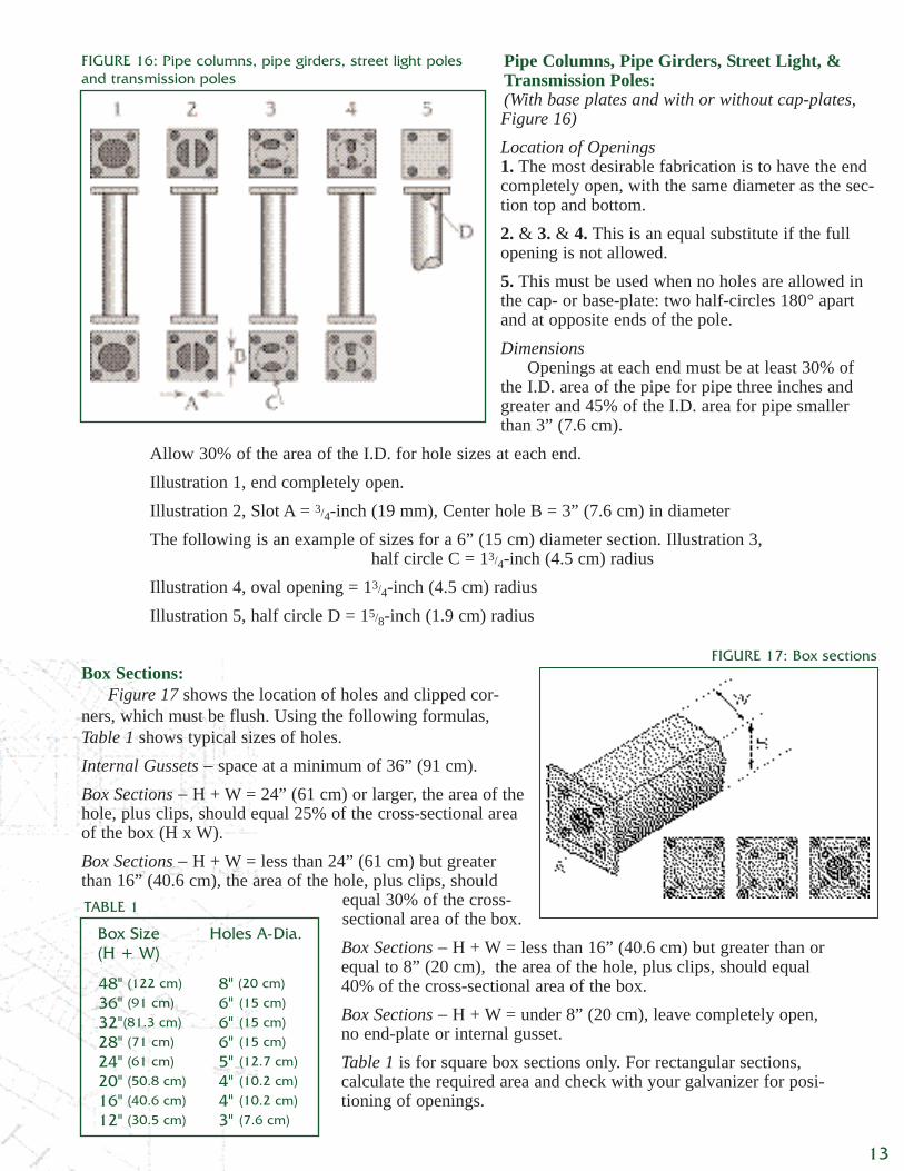
Box Sections:Figure 17 shows the location of holes and clipped cor-
ners, which must be flush. Using the following formulas,Table 1 shows typical sizes of holes.Internal Gussets − space at a minimum of 36” (91 cm).Box Sections − H + W = 24” (61 cm) or larger, the area of thehole, plus clips, should equal 25% of the cross-sectional areaof the box (H x W).Box Sections − H + W = less than 24” (61 cm) but greaterthan 16” (40.6 cm), the area of the hole, plus clips, should
equal 30% of the cross-sectional area of the box.Box Sections − H + W = less than 16” (40.6 cm) but greater than orequal to 8” (20 cm), the area of the hole, plus clips, should equal40% of the cross-sectional area of the box.Box Sections − H + W = under 8” (20 cm), leave completely open,no end-plate or internal gusset.Table 1 is for square box sections only. For rectangular sections,calculate the required area and check with your galvanizer for posi-tioning of openings.
Box Size Holes A-Dia.(H + W)
48" (122 cm) 8" (20 cm)
36" (91 cm) 6" (15 cm)
32"(81.3 cm) 6" (15 cm)
28" (71 cm) 6" (15 cm)
24" (61 cm) 5" (12.7 cm)
20" (50.8 cm) 4" (10.2 cm)
16" (40.6 cm) 4" (10.2 cm)
12" (30.5 cm) 3" (7.6 cm)
FIGURE 17: Box sections
TABLE 1
13
Internal gusset-platesand end-flanges should alsobe provided with vent anddrainage holes. In circularhollow shapes, the holesshould be located diametri-cally opposite each other atopposite ends of the mem-ber.
In rectangular hollowshapes, the four corners ofthe internal gusset-platesshould be cropped. Internalgusset-plates in all large hol-low sections should be pro-vided with an additional
opening at the center. Where there are flanges or end-plates, it is more eco-nomical to locate holes in the flanges or plates rather than in the section.
The following drawings illustrate recommended designs for tubular fab-rications and hollow structurals. The vent dimensions are the minimumrequired.
Designing for Proper Venting & Draining of Enclosed & Semi-Enclosed Products
Tanks and enclosed vessels should be designed to allow cleaning solu-tions, fluxes, and molten zinc to enter at the bottom and air to flow upwardthrough the enclosed space and out through an opening at the highest point.This prevents air from being trapped as the article is immersed (see Figure19). The design must also provide for complete drainage of both interiorand exterior details during withdrawal. The location and size of fill anddrain holes are important. As a general rule, the bigger the hole the betterthe air and zinc flow.
When both internal and external surfaces are to be galvanized, at leastone fill/drain hole and one vent hole must be provided. The fill/drain hole
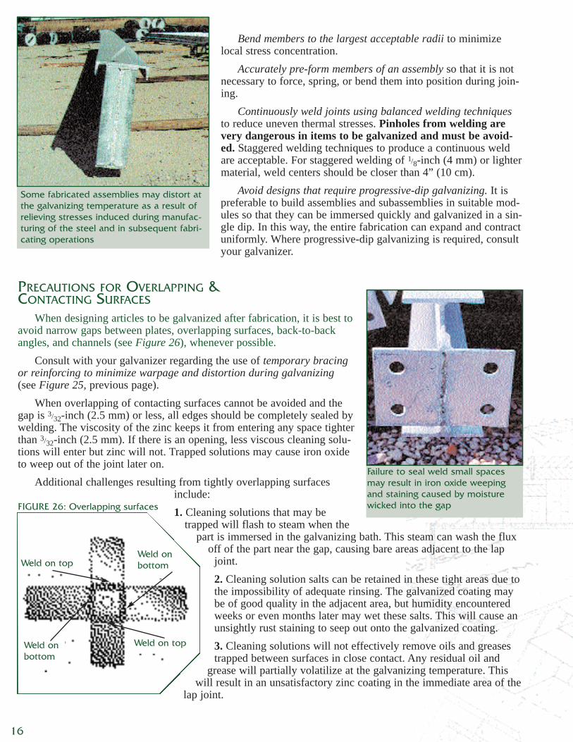
FIGURE 20: Venting of tanks &vessels
Gooddesign
Flush interiorsprovide gooddrainage
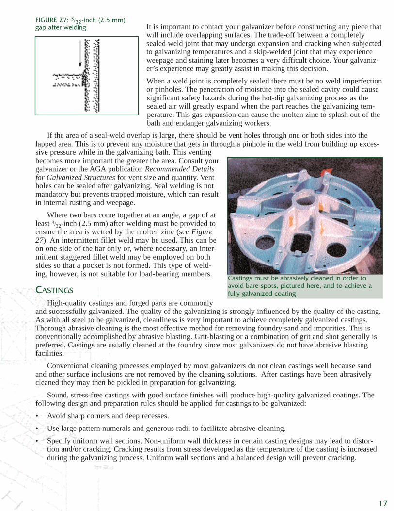
Poordesign
Trapped zinc
Trapped moisture, air, cleaning &flux solutions, & zinc
14
Tapered − Signal Arm:(Figure 18)A. The small end should be completely open.Pole Plate End1. The most desirable fabrication is to have theend completely open.2. & 3. & 4. For acceptable alternatives, thehalf-circles, slots, and round holes must equal30% of the area of the I.D. of the pole end of thetapered arm for 3” (7.6 cm) and larger I.D.s. Theopening must equal 45% of the area of the pole end of the tapered arm if the I.D. is less than 3” (7.6cm).
FIGURE 18: Tapered - signal arm
FIGURE 21: Improper venting
FIGURE 19Vent diagonally
opposite fill hole
Cropped internalbaffle (top andbottom)
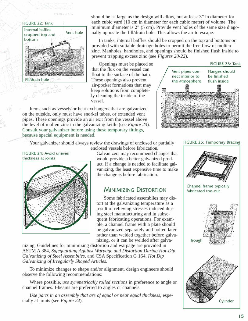
should be as large as the design will allow, but at least 3” in diameter foreach cubic yard (10 cm in diameter for each cubic meter) of volume. Theminimum diameter is 2” (5 cm). Provide vent holes of the same size diago-nally opposite the fill/drain hole. This allows the air to escape.
In tanks, internal baffles should be cropped on the top and bottoms orprovided with suitable drainage holes to permit the free flow of moltenzinc. Manholes, handholes, and openings should be finished flush inside toprevent trapping excess zinc (see Figures 20-22).
Openings must be placed sothat the flux on the vessel canfloat to the surface of the bath.These openings also preventair-pocket formations that maykeep solutions from complete-ly cleaning the inside of thevessel.
Items such as vessels or heat exchangers that are galvanizedon the outside, only must have snorkel tubes, or extended ventpipes. These openings provide an air exit from the vessel abovethe level of molten zinc in the galvanizing kettle (see Figure 23).Consult your galvanizer before using these temporary fittings,because special equipment is needed.
Your galvanizer should always review the drawings of enclosed or partiallyenclosed vessels before fabrication.
Galvanizers may recommend changes thatwould provide a better galvanized prod-uct. If a change is needed to facilitate gal-vanizing, the least expensive time to makethe change is before fabrication.
MINIMIZING DISTORTION
Some fabricated assemblies may dis-tort at the galvanizing temperature as aresult of relieving stresses induced dur-ing steel manufacturing and in subse-quent fabricating operations. For exam-ple, a channel frame with a plate shouldbe galvanized separately and bolted laterrather than welded together before galva-nizing, or it can be welded after galva-
nizing. Guidelines for minimizing distortion and warpage are provided inASTM A 384, Safeguarding Against Warpage and Distortion During Hot-DipGalvanizing of Steel Assemblies, and CSA Specification G 164, Hot DipGalvanizing of Irregularly Shaped Articles.
To minimize changes to shape and/or alignment, design engineers shouldobserve the following recommendations:
Where possible, use symmetrically rolled sections in preference to angle orchannel frames. I-beams are preferred to angles or channels.
Use parts in an assembly that are of equal or near equal thickness, espe-cially at joints (see Figure 24).
FIGURE 22: Tank
Vent hole
Fill/drain hole
Internal bafflescropped top andbottom
FIGURE 24: Avoid uneven thickness at joints
FIGURE 25: Temporary Bracing
Cylinder
Trough
Channel frame typicallyfabricated toe-out
15
FIGURE 23: Tank
Vent pipes con-nect interior tothe atmosphere
Flanges shouldbe finishedflush inside
Bend members to the largest acceptable radii to minimizelocal stress concentration.
Accurately pre-form members of an assembly so that it is notnecessary to force, spring, or bend them into position during join-ing.
Continuously weld joints using balanced welding techniquesto reduce uneven thermal stresses. Pinholes from welding arevery dangerous in items to be galvanized and must be avoid-ed. Staggered welding techniques to produce a continuous weldare acceptable. For staggered welding of 1/8-inch (4 mm) or lightermaterial, weld centers should be closer than 4” (10 cm).
Avoid designs that require progressive-dip galvanizing. It ispreferable to build assemblies and subassemblies in suitable mod-ules so that they can be immersed quickly and galvanized in a sin-gle dip. In this way, the entire fabrication can expand and contractuniformly. Where progressive-dip galvanizing is required, consultyour galvanizer.
PRECAUTIONS FOR OVERLAPPING &CONTACTING SURFACES
When designing articles to be galvanized after fabrication, it is best toavoid narrow gaps between plates, overlapping surfaces, back-to-backangles, and channels (see Figure 26), whenever possible.
Consult with your galvanizer regarding the use of temporary bracingor reinforcing to minimize warpage and distortion during galvanizing(see Figure 25, previous page).
When overlapping of contacting surfaces cannot be avoided and thegap is 3/32-inch (2.5 mm) or less, all edges should be completely sealed bywelding. The viscosity of the zinc keeps it from entering any space tighterthan 3/32-inch (2.5 mm). If there is an opening, less viscous cleaning solu-tions will enter but zinc will not. Trapped solutions may cause iron oxideto weep out of the joint later on.
Additional challenges resulting from tightly overlapping surfacesinclude:1. Cleaning solutions that may be
trapped will flash to steam when thepart is immersed in the galvanizing bath. This steam can wash the flux
off of the part near the gap, causing bare areas adjacent to the lapjoint.2. Cleaning solution salts can be retained in these tight areas due tothe impossibility of adequate rinsing. The galvanized coating maybe of good quality in the adjacent area, but humidity encounteredweeks or even months later may wet these salts. This will cause anunsightly rust staining to seep out onto the galvanized coating.3. Cleaning solutions will not effectively remove oils and greasestrapped between surfaces in close contact. Any residual oil and
grease will partially volatilize at the galvanizing temperature. Thiswill result in an unsatisfactory zinc coating in the immediate area of the
lap joint.
Failure to seal weld small spacesmay result in iron oxide weepingand staining caused by moisturewicked into the gapFIGURE 26: Overlapping surfaces
Weld on top
Weld on top
Weld onbottom
Weld onbottom
16
Some fabricated assemblies may distort atthe galvanizing temperature as a result ofrelieving stresses induced during manufac-turing of the steel and in subsequent fabri-cating operations
It is important to contact your galvanizer before constructing any piece thatwill include overlapping surfaces. The trade-off between a completelysealed weld joint that may undergo expansion and cracking when subjectedto galvanizing temperatures and a skip-welded joint that may experienceweepage and staining later becomes a very difficult choice. Your galvaniz-er’s experience may greatly assist in making this decision.When a weld joint is completely sealed there must be no weld imperfectionor pinholes. The penetration of moisture into the sealed cavity could causesignificant safety hazards during the hot-dip galvanizing process as thesealed air will greatly expand when the part reaches the galvanizing tem-perature. This gas expansion can cause the molten zinc to splash out of thebath and endanger galvanizing workers.
If the area of a seal-weld overlap is large, there should be vent holes through one or both sides into thelapped area. This is to prevent any moisture that gets in through a pinhole in the weld from building up exces-sive pressure while in the galvanizing bath. This ventingbecomes more important the greater the area. Consult yourgalvanizer or the AGA publication Recommended Detailsfor Galvanized Structures for vent size and quantity. Ventholes can be sealed after galvanizing. Seal welding is notmandatory but prevents trapped moisture, which can resultin internal rusting and weepage.
Where two bars come together at an angle, a gap of atleast 3/32-inch (2.5 mm) after welding must be provided toensure the area is wetted by the molten zinc (see Figure27). An intermittent fillet weld may be used. This can beon one side of the bar only or, where necessary, an inter-mittent staggered fillet weld may be employed on bothsides so that a pocket is not formed. This type of weld-ing, however, is not suitable for load-bearing members.
CASTINGS
High-quality castings and forged parts are commonlyand successfully galvanized. The quality of the galvanizing is strongly influenced by the quality of the casting.As with all steel to be galvanized, cleanliness is very important to achieve completely galvanized castings.Thorough abrasive cleaning is the most effective method for removing foundry sand and impurities. This isconventionally accomplished by abrasive blasting. Grit-blasting or a combination of grit and shot generally ispreferred. Castings are usually cleaned at the foundry since most galvanizers do not have abrasive blastingfacilities.
Conventional cleaning processes employed by most galvanizers do not clean castings well because sandand other surface inclusions are not removed by the cleaning solutions. After castings have been abrasivelycleaned they may then be pickled in preparation for galvanizing.
Sound, stress-free castings with good surface finishes will produce high-quality galvanized coatings. Thefollowing design and preparation rules should be applied for castings to be galvanized:• Avoid sharp corners and deep recesses.• Use large pattern numerals and generous radii to facilitate abrasive cleaning.• Specify uniform wall sections. Non-uniform wall thickness in certain casting designs may lead to distor-
tion and/or cracking. Cracking results from stress developed as the temperature of the casting is increasedduring the galvanizing process. Uniform wall sections and a balanced design will prevent cracking.
Castings must be abrasively cleaned in order toavoid bare spots, pictured here, and to achieve afully galvanized coating
17
FIGURE 27: 3/32-inch (2.5 mm) gap after welding
THREADED PARTS
Hot-dip galvanized fasteners are recommended for use with hot-dip gal-vanized subassemblies and assemblies. Galvanized nuts, bolts, and screwsin common sizes are readily available from commercial suppliers.
Bolted assemblies should be sent to the galvanizer in a disassembledcondition. Nuts, bolts, or studs to be galvanized also should be supplied dis-assembled.
Because hot-dip galvanizing is a coating of corrosion-inhibiting, highlyabrasion-resistant zinc on bare steel, the original steel becomes slightlythicker. When talking about tapped holes and fasteners, the increased thick-ness is important.
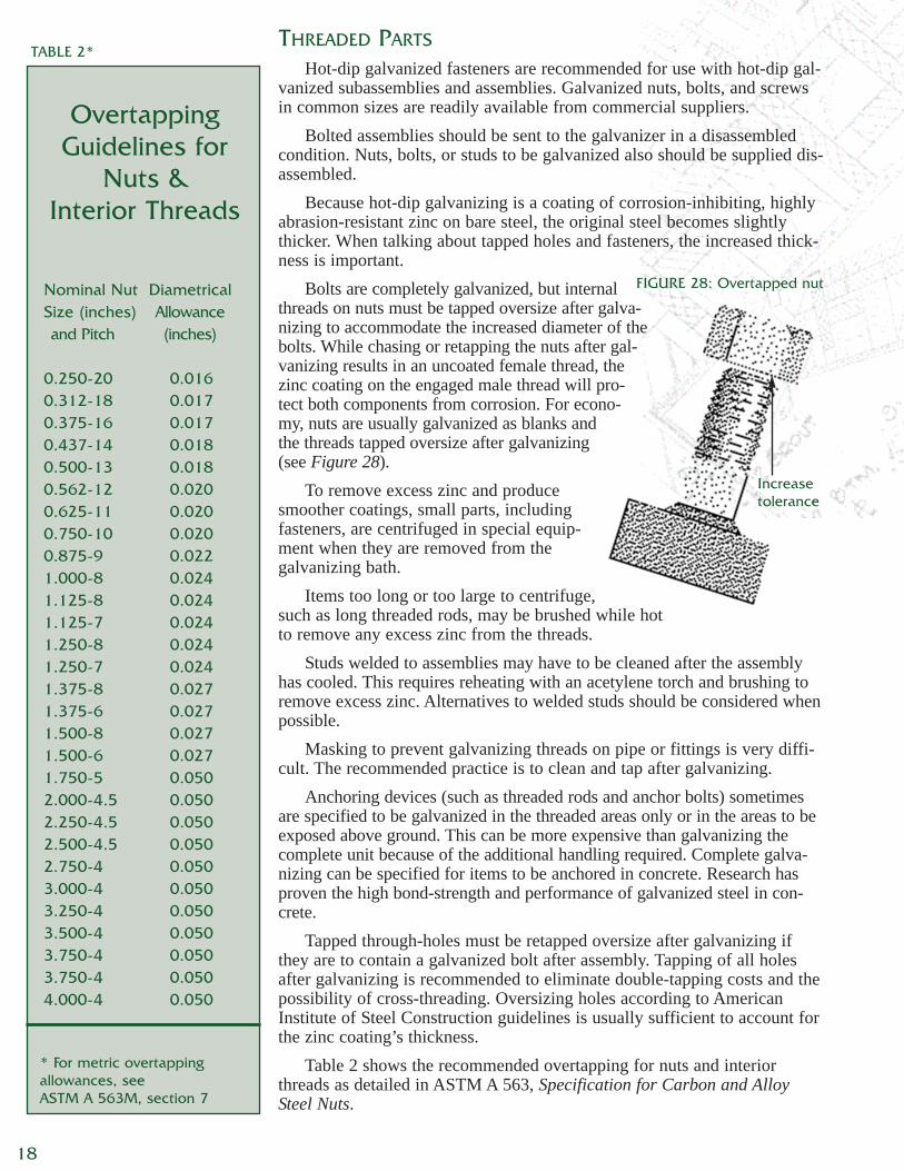
Bolts are completely galvanized, but internalthreads on nuts must be tapped oversize after galva-nizing to accommodate the increased diameter of thebolts. While chasing or retapping the nuts after gal-vanizing results in an uncoated female thread, thezinc coating on the engaged male thread will pro-tect both components from corrosion. For econo-my, nuts are usually galvanized as blanks andthe threads tapped oversize after galvanizing(see Figure 28).
To remove excess zinc and producesmoother coatings, small parts, includingfasteners, are centrifuged in special equip-ment when they are removed from thegalvanizing bath.
Items too long or too large to centrifuge,such as long threaded rods, may be brushed while hotto remove any excess zinc from the threads.
Studs welded to assemblies may have to be cleaned after the assemblyhas cooled. This requires reheating with an acetylene torch and brushing toremove excess zinc. Alternatives to welded studs should be considered whenpossible.
Masking to prevent galvanizing threads on pipe or fittings is very diffi-cult. The recommended practice is to clean and tap after galvanizing.
Anchoring devices (such as threaded rods and anchor bolts) sometimesare specified to be galvanized in the threaded areas only or in the areas to beexposed above ground. This can be more expensive than galvanizing thecomplete unit because of the additional handling required. Complete galva-nizing can be specified for items to be anchored in concrete. Research hasproven the high bond-strength and performance of galvanized steel in con-crete.
Tapped through-holes must be retapped oversize after galvanizing ifthey are to contain a galvanized bolt after assembly. Tapping of all holesafter galvanizing is recommended to eliminate double-tapping costs and thepossibility of cross-threading. Oversizing holes according to AmericanInstitute of Steel Construction guidelines is usually sufficient to account forthe zinc coating’s thickness.
Table 2 shows the recommended overtapping for nuts and interiorthreads as detailed in ASTM A 563, Specification for Carbon and AlloySteel Nuts.
* For metric overtappingallowances, seeASTM A 563M, section 7
OvertappingGuidelines for
Nuts &Interior Threads
Nominal Nut DiametricalSize (inches) Allowance and Pitch (inches)
0.250-20 0.0160.312-18 0.0170.375-16 0.0170.437-14 0.0180.500-13 0.0180.562-12 0.0200.625-11 0.0200.750-10 0.0200.875-9 0.0221.000-8 0.0241.125-8 0.0241.125-7 0.0241.250-8 0.0241.250-7 0.0241.375-8 0.0271.375-6 0.0271.500-8 0.0271.500-6 0.0271.750-5 0.0502.000-4.5 0.0502.250-4.5 0.0502.500-4.5 0.0502.750-4 0.0503.000-4 0.0503.250-4 0.0503.500-4 0.0503.750-4 0.0503.750-4 0.0504.000-4 0.050
TABLE 2*
FIGURE 28: Overtapped nut
Increasetolerance
18
On threads over 11/2-inches (38 mm) it is often more practical, if designstrength allows, to have the male thread cut 0.031-inches (0.8 mm) undersizebefore galvanizing so a standard tap can be used on the nut.
Manufacturers of threaded parts recognize that special procedures must befollowed in their plants when certain items are to be galvanized. Following aresome examples:• Low carbon bars are recommended since high carbon or high silicon cause
a heavier, rougher galvanized coating on the threads.• Hot-formed heading or bending requires cleaning at the manufacturing
plant to remove scale before threading. Otherwise, over-pickling of threadswill result during scale removal.
• Sharp manufacturing tools are mandatory. Ragged and torn threads openup in the pickling and galvanizing processes. Worn tools also increase boltdiameters. Frequent checking is necessary on long runs.
• Standard sized threads are cut on the bolt, while standard sized nuts areretapped oversize after galvanizing.
MOVING PARTS
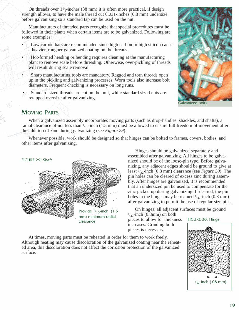
When a galvanized assembly incorporates moving parts (such as drop-handles, shackles, and shafts), aradial clearance of not less than 1/16-inch (1.5 mm) must be allowed to ensure full freedom of movement afterthe addition of zinc during galvanizing (see Figure 29).
Whenever possible, work should be designed so that hinges can be bolted to frames, covers, bodies, andother items after galvanizing.
Hinges should be galvanized separately andassembled after galvanizing. All hinges to be galva-nized should be of the loose-pin type. Before galva-nizing, any adjacent edges should be ground to give atleast 1/32-inch (0.8 mm) clearance (see Figure 30). Thepin holes can be cleared of excess zinc during assem-bly. After hinges are galvanized, it is recommendedthat an undersized pin be used to compensate for thezinc picked up during galvanizing. If desired, the pinholes in the hinges may be reamed 1/32-inch (0.8 mm)after galvanizing to permit the use of regular-size pins.
On hinges, all adjacent surfaces must be ground1/32-inch (0.8mm) on bothpieces to allow for thicknessincreases. Grinding bothpieces is necessary.
At times, moving parts must be reheated in order for them to work freely.Although heating may cause discoloration of the galvanized coating near the reheat-ed area, this discoloration does not affect the corrosion protection of the galvanizedsurface.
FIGURE 29: Shaft
FIGURE 30: Hinge
Provide 1/16-inch (1.5mm) minimum radialclearance
1/32-inch (.08 mm)
19
Galvanized bolts
MARKING FOR IDENTIFICATION
Identification markings on fabricated items should becarefully prepared before galvanizing so they will belegible after galvanizing but not disrupt the zinc coat-ing’s integrity.
Cleaning solutions used in the galvanizing processwill not remove oil-based paints, crayon markers or oil-based markers, so these products should not be used forapplying addresses, shipping instructions, or job numbers. Ifthese products are used, ungalvanized area may result.
Detachable metal tags or water-soluble markers shouldbe specified for temporary identification.
Where permanent identification is needed, there are threesuitable alternatives for marking steel fabrications to behot-dip galvanized. Each enables items to be rapidly identi-fied after galvanizing and at the job site (see Figures 31through 32).
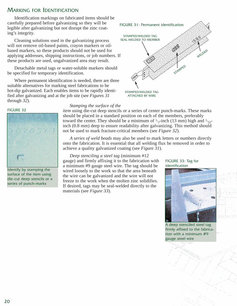
Stamping the surface of theitem using die-cut deep stencils or a series of center punch-marks. These marksshould be placed in a standard position on each of the members, preferablytoward the center. They should be a minimum of 1/2-inch (13 mm) high and 1/32-inch (0.8 mm) deep to ensure readability after galvanizing. This method shouldnot be used to mark fracture-critical members (see Figure 32).
A series of weld beads may also be used to mark letters or numbers directlyonto the fabrication. It is essential that all welding flux be removed in order toachieve a quality galvanized coating (see Figure 31).
Deep stenciling a steel tag (minimum #12gauge) and firmly affixing it to the fabrication witha minimum #9 gauge steel wire. The tag should bewired loosely to the work so that the area beneaththe wire can be galvanized and the wire will notfreeze to the work when the molten zinc solidifies.If desired, tags may be seal-welded directly to thematerials (see Figure 33).
FIGURE 33: Tag for identification
A deep stenciled steel tagfirmly affixed to the fabrica-tion with a minimum #9gauge steel wire
Identify by stamping thesurface of the item usingdie-cut deep stencils or aseries of punch-marks
20
FIGURE 31: Permanent identification
FIGURE 32
STAMPED/WELDED TAGSEAL-WELDED TO MEMBER
STAMPED/WELDED TAGATTACHED BY WIRE
STAMPED
WELDED
21
RELATED SPECIFICATIONS
ASTM A 36 Specification for Structural SteelASTM A 123 Specification for Zinc (Hot-Dip Galvanized) Coatings on Iron and
Steel ProductsASTM A 143 Practice for Safeguarding Against Embrittlement of Hot-Dip
Galvanized Structural Steel Products and Procedure for DetectingEmbrittlement
ASTM A 153 Specification for Zinc Coating (Hot-Dip) on Iron and SteelHardware
ASTM A 384 Practice for Safeguarding Against Warpage and Distortion DuringHot-Dip Galvanizing of Steel Assemblies
ASTM A 385 Practice for Providing High Quality Zinc Coatings (Hot-Dip)ASTM A 563 Specification for Carbon and Alloy Steel NutsASTM A 572 Specification for High-Strength Low-Alloy Columbium-Vanadium
Structural SteelASTM A 767 Specification for Zinc-Coated (Galvanized) Steel Bars for Concrete
ReinforcementASTM A 780 Practice for Repair of Damaged and Uncoated Areas of Hot-Dip
Galvanized CoatingsASTM B 6 Specification for ZincASTM D 6386 Practice for Preparation of Zinc (Hot-Dip Galvanized) Coated Iron
and Steel Product and Hardware Surfaces for PaintingASTM E 376 Practice for Measuring Coating Thickness by Magnetic-Field or
Eddy-Current (Electromagnetic) Test Methods
G 40.8* Structural Steel with Improved Resistance to Brittle FractureG 40.12* General Purpose Structural SteelG 164 Galvanizing of Irregularly Shaped Articles
*Superseded by G 40.20/G 40.21 General Requirements for Rolled or WeldedStructural Quality Steel
Duplex Systems: Painting Over Hot Dip Galvanized SteelAmerican Galvanizers Association, Aurora, Colo., 1998.Inspection of Products to be Hot Dip Galvanized After Fabrication: Including aNew Section on Touch-up & RepairAmerican Galvanizers Association, Englewood, Colo., 2001.Recommended Details for Galvanized StructuresAmerican Galvanizers Association, Aurora, Colo., 1990.Welding & Hot-Dip GalvanizingAmerican Galvanizers Association, Englewood, Colo., 2002.Wet Storage StainAmerican Galvanizers Association, Aurora, Colo., 1997.
CanadianStandardsAssociation
FurtherReading &RelatedMaterials
AmericanSociety forTesting &Materials
American Galvanizers Association6881 South Holly Circle, Suite 108Englewood, Colorado 80112Phone: 800-468-7732Fax: [email protected]