Embed Size (px)
Citation preview
The design of soft fluid filled actuators driven by conductive nylon
by Lee Sutton
B.A.Sc. (Mechanical Engineering) University of British Columbia, 2014
Thesis Submitted in Partial Fulfillment of the Requirements for the Degree of
Master of Applied Science
in the School of Engineering Science
Faculty Applied Sciences
© Lee Sutton 2019 SIMON FRASER UNIVERSITY
Fall 2019
Copyright in this work rests with the author. Please ensure that any reproduction or re-use is done in accordance with the relevant national copyright legislation.

ii
Approval
Name: Lee Sutton Degree: Master of Applied Science Title: The design of soft fluid filled actuators driven by
conductive nylon Examining Committee: Chair: Kamal Gupta
Professor
Carlo Menon Senior Supervisor Professor, Schools of Mechatronics Systems Engineering and Engineering Science
Woo Soo Kim Supervisor Professor, School of Mechatronic Systems Engineering
Michael Adachi Internal Examiner Assistant Professor
Date Defended/Approved: September 17, 2019

iii
Abstract
Soft robots have become increasingly prevalent due to their distinct advantages over
traditional rigid robots such as high deformability and good impact resistance. However,
soft robotics are currently limited by bulky, non-portable methods of actuation. In this
study, we propose a soft actuator driven by conductive nylon artificial muscles which is
able to produce forces up to 1.2N. By utilizing nylon artificial muscles, the system does
not require sizable pumps or compressors for actuation. The proposed actuator is made
up of two main components, a sealed bladder filled with air and an arrangement of nylon
artificial muscles. The quasi static behavior of the actuator is characterized using
established hyper elastic models and validated against experimental results (maximum
error of 5.3%). Using these models, a set of design considerations are formulated which
outline the achievable torques for various actuator dimensions.
Keywords: soft robotics; artificial muscles; nylon; fluidic actuator; polymer

iv
Acknowledgements
I would like to thank Dr. Carlo Menon, my senior supervisor for his support and
guidance, Dr. Michael Adachi, Dr. Woo Soo Kim for being my committee. Special thanks
to Hadi Moein and Shahram Pourazadi for contributing their time towards aiding me to
conduct research experiments. I would also like to thank all members of MENRVA
research group for their help and support. Last but not least, I would like to thank my
family and my Fiancédf Ali White for providing me with support and encouragement.

v
Table of Contents
Approval ............................................................................................................................. ii Abstract .............................................................................................................................. iii Acknowledgements ............................................................................................................ iv Table of Contents ................................................................................................................ v List of Figures ................................................................................................................... vii List of Acronyms ............................................................................................................... xi
Chapter 1. Introduction ............................................................................................. 1 1.1. Background ............................................................................................................... 1 1.2. Motivation ................................................................................................................. 2 1.3. Objectives ................................................................................................................. 3 1.3 Thesis Layout ................................................................................................................ 4
Chapter 2. Literature Review .................................................................................... 7 2.1. Soft Robotics ............................................................................................................. 7 2.2. Intrinsically Soft Materials ....................................................................................... 8 2.3. Actuation technologies ............................................................................................. 9
2.3.1. Pneumatic actuation .......................................................................................... 9 2.3.2. Actuation using smart materials ..................................................................... 12 2.3.3. Cable driven actuation .................................................................................... 16
2.4. Soft Robotics Applications ..................................................................................... 18 2.4.1. Grippers and Manipulators ............................................................................. 18 2.4.2. Medical Applications ...................................................................................... 20 2.4.3. Wearable applications..................................................................................... 22 2.4.4. Locomotion ..................................................................................................... 27
2.5. Control Systems ...................................................................................................... 29 2.6. Challenges ............................................................................................................... 31
Chapter 3. Actuator Design and Early Stage Prototype ....................................... 34 3.1. Actuator Concept .................................................................................................... 34 3.2. Actuator Prototype .................................................................................................. 35
Chapter 4. Analytical Modelling ............................................................................. 38 4.1. Nylon Thermo-Electric Model ................................................................................ 38 4.2. Silicone Material Model ......................................................................................... 40 4.3. Quasi-static Modelling ............................................................................................ 42
Chapter 5. Experimental Results ............................................................................ 46 5.1. Internal Pressure Model Validation ........................................................................ 46 5.2. Position Model Validation ...................................................................................... 47

vi
5.3. Force Model Validation .......................................................................................... 51 5.4. Position Controller .................................................................................................. 54 5.5. Soft Gripper Demonstration .................................................................................... 58
Chapter 6. Design Considerations ........................................................................... 63 6.1. Nylon Limitations ................................................................................................... 63 6.2. Maximum Achievable Torque ................................................................................ 65 6.3. Range of motion ...................................................................................................... 66
Chapter 7. Discussion ............................................................................................... 69
Chapter 8. Future Work .......................................................................................... 72 8.1. Potential Applications ............................................................................................. 72 8.2. Actuator Development ............................................................................................ 76
Chapter 9. Conclusion .............................................................................................. 85
Bibliography .................................................................................................................... 87

vii
List of Figures
Figure 1 Approximate Young's modulus of selected engineering and materials. Image reproduced with permissions from [1] ........................................................ 8
Figure 2 (a) McKibben actuator reproduced with permissions from [37] (b, c) fluid elastomer actuators from [38] (d) pneu-net molded fluid actuator from [39]. (d) Foam based fluidic actuator [40]. Image reproduced with permissions from [3] ................................................................................. 11
Figure 3 (a) Hydraulic artificial muscle attached to a skeletal arm. Image reproduced with permissions from [40](b) Time sequence of a jumping robot powered by chemical explosions. Image reproduced with permissions from [44] ...... 12
Figure 4 (a) Soft robotic octopus arm powered by SMA coil actuators. Image reproduced with permissions from [16]. Jellyfish soft robot powered by SMA actuators [52]. (c) A self contained soft fish robot powered by SMA actuators. Image reproduced with permissions from [53]. (d) A resilient earth worm robot coiled with SMA actuators to produce locomotion. Image reproduced with permissions from [50]. ........................................ 14
Figure 5 (a) A rollable soft gripper powered by DEA actuators. Image reproduced with permissions from [51]. An electro adhesion gripper actuated with DEA’s. Image reproduced with permission from [52]. A soft bendable actuator used in the development of a DEA powered soft gripper. Image reproduced with permissions from [53]. ................................................... 15
Figure 6 (a) A planar swimming robot powered by ionic polymer artificial muscles. Image reproduced with permissions from [63] (b) A soft jellyfish inspired robot actuated with ionic polymer metal composite muscles. Image reproduced with permissions from [65]. ................................................... 16
Figure 7. (a) A cosmetic prosthetic hand driven with cable actuators arranged along the joint path. Image reproduced with permissions from [68]. A soft robotic manipulator activated by cable driven actuators. Image reproduced with permissions from [62]. (c) A bioinspired continuous manipulator which utilizes pressure and tendon driven actuation. Image reproduced with permissions from [70]. (d) A soft wearable robot for hand assistance. The robot uses a tendon driven actuation system aligned with the hand joints to assist with flexion and extension. Image reproduced with permissions from[66] .................................................................................................... 17
Figure 8. Some applications of the soft manipulators. (a) Soft Robotics’ gripper handling food item (reproduced with permission from [90]). (b) Theragripper grasping a group of cells [92]. (c) Grabit electroadhesion soft gripper. (d) Soft gripper being used for underwater application [42]. Images reproduced with permissions from [90] [91] [41] [42] ............................. 19
Figure 9 Soft robotic actuators arranged to mimic heart pumping motion. (a) Soft pneumatic actuators arranged helically to simulate the pumping and twisting motion of the heart [95]. (b) Heart fluid pump produced using

viii
foam based soft fluidic actuators. Soft Robotic-Based Heart Actuators. [40]. Image reproduced with permissions from [3] .................................. 21
Figure 10 Design of theragripper drub delivery system (a) schematic of the theragripper device. (b) Open and closed theragrippers. (c) Conceptual illuastration of theragrippers inside the body. Image reproduced with permissions from [87] ............................................................................................................ 22
Figure 11 Wearable or assistive soft robotic devices. (a) Wearable soft robotic device for the wrist [105]. (b) Soft pneumatic wearable elbow assistive device. [106] (c) Wearable assistive device for the foot and ankle [108]. (d) Wearable assistive device for the hand [75]. (d) Lightweight soft exoskeleton for lower body gait assistance. [107]. Images reproduced with permissions from [105], [106], [75], [107], and [108] respectively. ............................ 26
Figure 12 (a) A resilient earth worm robot coiled with SMA actuators to produce locomotion. Image reproduced with permissions from [51]. (b) caterpillar inspired locomotive robot. Fabricated from silicone and tethered to its power source. Image reproduced with permissions from [109] (c) A soft robotic fish which was able to swim and manouvre. Image reproduced with permissions from [110]. .................................................................... 28
Figure 13 Depiction of actuator operation. Reproduced from [15] .................................. 35 Figure 14. Depiction of the soft actuator fabrication process. (a) Molding the actuator
body using a 3-D printed part. (b) The nylon strain limiting layer is attached to the flat face of the actuator. Nylon is wound along the entire length of the actuator. The steel rod is removed from the silicone body and the ends are closed off with silicone. One end is sealed with a vented screw connected to a pressure sensor to measure the internal air pressure in the actuator. Reproduced from [15] ...................................................... 36
Figure 15. Fabricated actuator. (a) Top view of the silicone actuator after being removed from the mold (b) Bottom view of silicone actuator showing the axially arranged nylon artificial muscles. (c) Silicone actuator wrapped in nylon artificial muscles (top view). Reproduced from [15] ................................ 37
Figure 16 (a) The measured actuator bending angle (b) A cross section view of the actuator with labelled dimensions. Reproduced from [15] ....................... 44
Figure 17 Internal pressure versus nylon tensile stroke plotted against the analytics model. Reproduced from [15] ................................................................... 47
Figure 18 Actuator analytical model visualized against a bending actuator. Reproduced from [15] ................................................................................................... 48
Figure 19 Bending angle versus pressure, for radius values ranging from 6.0 to 14.0mm. Reproduced from [15] ............................................................................... 49
Figure 20. Bending angle versus pressure, for wall thickness ranging from 1.0 to 4.0mm. Reproduced from [15] ............................................................................... 50
Figure 21 Actuator force measured with the top layer constrained .................................. 51 Figure 22 Force measurements of the actuator versus internal pressure for various radii.
Reproduced from [15] ............................................................................... 52

ix
Figure 23 Force measurements of the actuator versus internal pressure for various actuator lengths. Reproduced from [15] ................................................... 53
Figure 24 Actuator forces versus internal pressure for various actuator wall thicknesses. Reproduced from [15] ............................................................................... 54
Figure 25 Schematic of control system for each actuator. Each actuator was equipped with a pressure sensor and the power was modulated to the nylon using a RFP30N06LE MOSFET. .......................................................................... 55
Figure 27 Schematic of the closed loop controller for actuator bending angle. Reproduced from [15] ................................................................................................... 56
Figure 28 Feedback control loop performance. Actuator tracking a sinusoidal reference angle with a period of 0.04Hz. Reproduced from [15] ............................. 57
Figure 29 Feedback control loop performance. Step response of the actuator controller. Reproduced from [15] ............................................................................... 58
Figure 29 Top down view of the internals of the gripper demonstration. Each actautor is equipped with a pressure sensor which is connected to an arduino mega. The power to each actuator is modulated using a RFP30N06LE MOSFET controlled by the arduino. ......................................................................... 59
Figure 30 Soft gripper demonstration. The soft gripper shown grasping a ping pong ball through all stages of grasping. Reproduced from [15] ............................. 60
Figure 31 The soft gripper shown grasping various objects. ............................................ 61 Figure 32 Plot of pressure versus time for the actuators in the gripper ............................ 62 Figure 33 Depiction of the nylon wrapping angle ............................................................ 64 Figure 34 Forces in the nylon versus. tensile stroke for various actuator dimensions ..... 65 Figure 35 Maximum achievable torques for versus actuator dimensions. Actuator
limitations shown as a dashed black line .................................................. 66 Figure 36 Maximum achievable range of motion versus actuator dimensions. Actuator
limitations shown as a black dashed line. ................................................. 67 Figure 37 A soft wearable assistive device for the hand, powered by pneumatic actuators
and tethered to a pneumatic compressor. Reproduced with permissions from [145] ................................................................................................. 73
Figure 38 (a) A soft robotic rehabilitation device for the hand. (b) A patient utilizing the device under superision of the clinician. The pump and control box required to activate the device are also depicted. Reproduced with permissions from [107] ............................................................................. 74
Figure 39 A soft robotic system used to sample deep coral reefs. The robot is currently limited by its tethers to its pneumatic power source. Reproduced with permissions from [146] ............................................................................. 75
Figure 40 A soft robotic system used to mimic snake like locomotion for environmental monitoring purposes. The robot is currently limited by its bulky rigid pneumatic compressor. Reproduced with permissions from [147] .......... 76

x
Figure 41 Perspective views of the fluidic actuator which uses artificial muscles to increase the internal pressure, elongating the actuator. ............................ 77
Figure 42 Perspective views of the fluidic actuator with artificial muscles arranged to twist the actuator around the central axis. ................................................. 78
Figure 43 Illustration of a bending fluidic actuator with actuators arranged to bend and twist the actuator. ...................................................................................... 79
Figure 44 Illustration of a bending fluidic actuator with actuators arranged to bend and twist the actuator in both directions by activating each set of axial nylon wires individually. The activated nylon is shown in red and the resulting bending configuration is shown above. .................................................... 80
Figure 45 Illustration of a bending fluidic actuator with actuators arranged to allow for planar movement. ...................................................................................... 81
Figure 46 Illustration of a bending fluidic actuator with actuators 3 actuators arranged in a compact cylinder to allow for planar movement. ................................... 82
Figure 47 Illustration of a bending fluidic actuator with one fluidic actuator and 3 axial nylon wires arranged in parallel to allow for planar movement. .............. 83
Figure 48 Illustration of a bending fluidic actuator with actuators 2 actuators arranged in a compact cylinder to allow for planar movement. ................................... 84

xi
List of Acronyms
SFU Simon Fraser University DEA Dielectric elastomer Actuators SMA Shape memory alloy IPMC Ionic polymer-metal composite actuator MENRVA Mechanisms N Robotics for Viable Applications
1
Chapter 1. Introduction
1.1. Background
Biology has for some time, been a source of inspiration for engineers designing
more adaptable machines. Biological systems rely on body compliance and softness to
effortlessly interact with complex environments. These biological systems have inspired
designers in the creation of a new class of machines referred to as soft robots.
Conventional, rigid robots are used for a variety of applications where they perform
exceedingly well when programmed to perform a single task however, often with limited
adaptability [1]. In addition, due to their rigid nature, conventional robots are unsafe for
interaction with humans [2]. As a result, it is common practice to separate work spaces
for humans and robots to prevent collisions and mitigate safety concerns [2]. The limited
compliance in conventional robotic systems is large contributor to this problem. Soft
robots provide an opportunity to bridge this gap between human and robotic interactions.
Due to the compliant nature of soft robotic systems, the body of the robot is able to
absorb the majority of the energy in the case of a collision [3]. These robots consist of a
continuously deformable structure paired with muscle like actuation technologies that
emulate biological systems. As a result, these systems are able capable of deforming
with a large number of degrees of freedom when compared to their rigid counterparts [3].
Soft robotics offers an alternative solution to rigid systems, with increased adaptability,
agility, and reduced complexity when interacting with their environments.

2
1.2. Motivation
Soft robots have become increasingly prevalent due to their distinct advantages
over traditional rigid robots such as high deformability and good impact resistance. One
of the biggest challenges for soft robotics is the design of extendable, portable methods
for actuation [1]. The segments of a soft robot are typically actuated in one of two ways:
tendons of varying length may be embedded into the soft segments to achieve motion;
or pneumatic actuation may be used to pressurize inflatable channels which cause the
material to deform to the desired deformation [1]. Tendon systems typically rely on
electric motors to contract. Electric motors produce high specific power outputs, but
require transmission systems to perform non-repetitive tasks, which increases the size,
and weight of the overall system [2]. Pneumatic actuators rely on external pressure
sources that are generally limited to pumps, compressors, or cylinders of compressed air
[3].
Biological muscles offer many advantages over electric motors and pneumatic
actuation methods. Skeletal muscles can produce large forces under varying strains,
exhibit fast actuation times, and have high power- to-weight ratios [4]. Researchers in
the field of artificial muscles aim to create an actuator that matches these desirable
properties. Some of the technologies currently being examined include piezoelectric
polymers, shape memory alloys, ferroelectric dielectric elastomers, and polyelectrode
gels [2] [5] [6] [7]. These materials deform when a chemical, electrical, or thermal stress
is applied [8]. However, these technologies suffer from certain limitations such as low life
cycle, hysteresis, high voltage requirements, and low efficiency [2] [9] [10]. A muscle-like
technology whose performance could match that of skeletal muscle would be beneficial
for the field of soft robotics.

3
Haines et al. recently discovered a new type of artificial muscles that match or
exceed the performance of biological muscles [11]. These artificial muscles are
produced by coiling nylon fibres. Nylon fibres are made up of polymer chains oriented in
the fibre direction which undergo large reversible contractions when heated. Haines et
al. showed that uncoiled nylon fibres can contract up to 4% when a thermal load is
applied. They showed that the tensile stroke may be amplified by coiling the fibres to
make them chiral. Depending on the coil parameters, the coiled fibres may contract up to
49%, exceeding skeletal muscles (20%) [11]. In addition, nylon actuators have been
shown to generate power densities of up to 5.3kW/kg, compared to 0.32kW/kg for the
average human skeletal muscle [9].
In this study, soft actuators are proposed which make use of nylon artificial
muscles to produce a soft fluidic actuator with no requirement for an external
compressor. The artificial muscles are arranged to increase the pressure of the internal
fluid while providing a backbone to produce bending motion. The internal fluid provides
the proposed actuators with a compliant structure much like pneumatically-driven soft
actuators. This study examines the feasibility of using the proposed actuators by
investigating the system both analytically and experimentally.
1.3. Objectives
The objectives of this thesis are to:
1. Explore the feasibility of developing a soft bending fluidic actuator which
makes use of nylon artificial muscles eliminating the need for an external
compressor or pump
2. Utilize established hyper elastic models to investigate the quasi-static
behaviour of the proposed fluidic actuator

4
3. Verify the proposed model
4. Characterize the performance of the proposed fluidic actuator
1.3 Thesis Layout
The thesis has the following layout. Chapter 2 presents an in-depth literature
review of the field of soft robotics. A general overview of the field is discussed and its
recent emergence into fields where conventional rigid robotics were typically used. Next,
a number of soft robotic actuation technologies are explored including pneumatic
actuators, smart materials, and cable driven actuators. These technologies have
enabled soft robotics to enter into a number of new applications. Some of these
applications are explored including soft robotic grippers, medical applications, wearable
applications, and soft locomotive robots. Based on these actuation technologies, various
soft robotic control systems are reviewed. Lastly, the persistent challenges in soft
robotics development are highlighted.
Chapter 3 presents the proposed actuator design and the fabrication of an initial
prototype. In this chapter, the actuator operating principles are outlined along with a
proposed fabrication method for the sealed fluid bladder and coiled nylon fibres. Finally,
an initial prototype is constructed using the proposed methods and presented at the end
of this section.
In chapter 4 and analytical model is developed for the proposed actuator design.
To enable the robotics research community to utilize the proposed actuator, analytical
models were formulated to predict the actuator’s quasi-static behaviour and validated
against the experimental results. This provides robotics designers with information on
the actuator’s performance prior to manufacturing. The variables in the models were the
nylon thermo-electric properties, the actuator dimensions, and the material properties of

5
the silicone bladder. The outputs of the model were the actuator position and the forces
generated at the actuator tip.
Chapter 5 validates the analytical models proposed in chapter 4 against
experimental results. Six variations of the proposed actuator are fabricated and tested to
verify the proposed position and force models. After validating the analytical models, a
position controller was developed to demonstrate the simplicity at which the proposed
actuator may be controlled. This controller is then used to provide evidence of the
potential ability of the soft actuator to be used in robotic applications
Chapter 6 examines the validated analytical models and outlines a set of design
considerations for the proposed actuator. The proposed fluidic actuator may be suitable
for applications where pressure driven actuators are currently used. However, the size
and forces generated by the actuator are limited by the capabilities of the nylon artificial
muscles. It is important for the robotics designer to understand how these limitations
affect the actuator’s capabilities. Using the models developed in chapter 4, a set of
theoretical limits is calculated based on the physical dimensions of the actuator to
establish the maximum achievable torques and maximum actuator dimensions for a full
range of motion.
The vast majority of the thesis is reproduced with permission from the following
papers I co-authored:
Sutton, L & Menon C (2019) A soft fluidic actuator based on nylon artificial
muscles. Engineering Research Express. Manuscript accepted for publication [15]
Kaur, R, Sutton, L & Menon C (2019) Soft Grippers: A state of the art review.
Robotica. Manuscript submitted for publication. [16]

6
Sutton L, Moein H, Rafiee A, Madden JD, Menon C. Design of an assistive wrist
orthosis using conductive nylon actuators. In2016 6th IEEE International Conference on
Biomedical Robotics and Biomechatronics (BioRob) 2016 Jun 26 (pp. 1074-1079). IEEE.
[16]

7
Chapter 2. Literature Review
This chapter presents a review on the current state of the art in the field of soft
robotics including actuation technologies, soft robotics applications, control systems, and
persistent challenges moving forward. on the proposed actuator design and the
fabrication process for the initial prototypes. Sections of this chapter are excerpts from
the following papers which I co-authored:
Kaur, R, Sutton, L & Menon C (2019) Soft Grippers: A state of the art review.
Robotica. Manuscript submitted for publication
Sutton L, Moein H, Rafiee A, Madden JD, Menon C. Design of an assistive wrist
orthosis using conductive nylon actuators. In 2016 6th IEEE International Conference on
Biomedical Robotics and Biomechatronics (BioRob) 2016 Jun 26 (pp. 1074-1079). IEEE.
2.1. Soft Robotics
Conventional robotic systems are composed of metals, or hard plastics with
moduli with moduli in the range of 109– 1012 𝑃𝑃𝑃𝑃 (Figure 1) [1]. These rigid bodied robots
are used in a number of applications where they may be programmed to perform specific
tasks efficiently. However, due to their rigid nature, they usually perform these tasks with
limited adaptability. In addition, these rigid systems are often unsafe for interactions with
humans. To overcome these limitations, engineers have begun to explore using soft
materials to build robots. The body of these soft robots are made out of soft materials
that can absorb energy and deform in the case of a collision. Due to their flexible
structure, these robots exhibit a large number of degrees of freedom. This allows them
to exhibit increased levels of adaptivity when compared to rigid bodied robots. Recent
developments have shown these robots twisting and bending with high curvatures in a

8
continuous way allowing them to achieve motions that emulate biology [15], employ
compliant motion to manipulate objects, move in rough terrain [16], and execute rapid
agile maneuvers [17]. Soft robotics is rapidly entering new areas of active development,
in the following sections, the underlying actuation technologies, some of the common
applications of soft robotics, and the challenges moving forward are explored.
Figure 1 Approximate Young's modulus of selected engineering and materials. Image reproduced with permissions from [1]
2.2. Intrinsically Soft Materials
Recent developments in the design of soft materials has been one of the key
enablers for the soft robotics community. Conventional robotic systems typically made
use of hard materials such as metals or hard plastics which have a Young’s modulus in
the range of 109–1012 Pa [4]. On the contrary, biological systems are often composed of
materials such as skin, or muscle tissue, with a Young’s modulus in the range of 104–109
Pa [4]. The soft robotics community has taken inspiration from these biological systems
begun to design autonomous systems that are primarily made of up materials with a
Young’s modulus in the range of soft biological materials.
Historically, advanced elastomers with low Young’s modulus, high strains, and
toughness were not available from commercial vendors until relatively recently. On the
contrary, metals and ceramics have been globally available for use for thousands of
years [18]. Although natural rubber was available from the Hevea brasilinesis tree, it was

9
not vulcanized until the 19th century. It also does not provide the required properties for
use in soft robotics [3]. In 1948 Dow-Corning was the first to release a commercially
available resilient silicone [3]. Eventually, these silicones started to see use as gaskets,
sealants and coatings, however it wasn’t until recently when these materials started to
be used as the machinery itself. These soft materials with a Young’s modulus similar to
that of biological materials offer many advantages over rigid materials. They offer a
considerable reduction in harm that could be caused by a collision with a rigid material
[19]. This is beneficial to the robotics community as inadvertent collisions can potentially
occur during human robot interaction. In addition, these compliant materials readily
adapt to the shapes of various objects making tasks such as grasping significantly less
complex. Furthermore, these soft materials can lead to improved mobility for locomotion
robots exploring unknown terrain [20].
2.3. Actuation technologies
Soft robotic systems require a flexible actuation system. These actuation
systems often take inspiration from biological muscles because of their deformability and
adaptability. A number of flexible actuation systems have been proposed. These
systems involve force that is transmitted by a fluidic pressure inside the soft structure,
through cables embedded in the structure, or by using smart materials such as dielectric
elastomers (DEA) or shape memory alloys (SMA).
2.3.1. Pneumatic actuation
Robots powered by pneumatic actuation use a pressurized fluid to deform the
soft robotic structure to a desired configuration. These motions may include elongation,
contraction, twisting, bending or any complex combination of all these [15]. The desired

10
motions are achieved by structural constraints and through control of the fluid pressure
inside the inflatable chambers [16]. The inherently compliant structure of the robot allows
it to change its compliance according to the change in pressure of the fluid inside. These
characteristics allow pressure controlled soft robots to distribute the pressure uniformly
over large areas without elaborate controls and thus allow them to manipulate fragile
and irregular shaped objects.
McKibben et al. was one of the first to propose pneumatic muscle actuators to
assist patients with paralyzed hands [17]. The proposed muscles are made up an
inflatable rubber tube housed in a rigid helically wound braid (Figure 2 a). When the tube
is pressurized, the muscle expands radially and contracts axially. These muscles exhibit
characteristics similar to that of biological muscles and have been studied extensively
[24], [25], [26], [27], [28] [29], [30].
The muscles proposed by McKibben et al. only allow for deformation in the linear
direction. To overcome these limitations, researchers have begun to explore channeled
actuators to allow for more complex motions. These actuators are composed of an
elastomer embedded with a network of internal channels, and a stiff layer bonded to the
elastomer. The difference in the young’s modulus of the two materials and the design of
the internal network cause the actuator to bend to the desired configuration upon
pressurization [31], [32] (Figure 2 b-e). Chang et al. was one of the first to propose a
channelled bending fluidic actuator. The actuator used a unique fluidic channel
embedded in a soft silicon structure bonded to a thin stiff material [22]. This work was
adapted by Ilievski in the creation of a new pneumatic network actuator (PneuNets) [33].
These PneuNets actuators were used in a number of soft robotic designs including:
Shepherd’s puncture resistant actuator [34], Stokes’ soft quadruped [35], Tolley’s
walking robot [1] Homber's soft gripper [36].

11
Figure 2 (a) McKibben actuator reproduced with permissions from [37] (b, c) fluid elastomer actuators from [38] (d) pneu-net molded fluid actuator from [39]. (d) Foam based fluidic actuator [40]. Image reproduced with permissions from [3]
Most actuators are controlled by pressurized air as it presents many advantages
over the use of other fluids [32]. However, hydraulic actuation is used in cases where
higher forces are required [40], [41], [42]. A comparison between pneumatic and
hydraulic actuation was conducted by Trivedi [43] in the development of a soft robotic
octopus arm. Yamaguchi et al. examined a different type of fluid working fluid in in the
design of a robotic hand [44]. The robotic hand used an electro-conjugate fluid that

12
produces a jet flow when subjected to a high DC voltage. The jet flow pressurizing the
fingers allows them to bend. Furthermore, the pressure generation by chemical reactions
to power the soft bodied robot has also been developed [45], [34], [46] [47].
(a) (b)
Figure 3 (a) Hydraulic artificial muscle attached to a skeletal arm. Image reproduced with permissions from [40](b) Time sequence of a jumping robot powered by chemical explosions. Image reproduced with permissions from [44]
2.3.2. Actuation using smart materials
Advances in the field of materials science has introduced various materials with
intelligence embedded at the molecular level. These materials respond to electrical or
thermal stimuli by altering their shape [48]. Several of these smart materials including
SMAs and EAPS are finding use in soft robotics.
Shape memory alloys (SMAs) have the unique ability to recover from a plastic
strain when they are heated above a certain temperature. This property is exploited in

13
the development of SMA muscles which make use of coiled SMA wires that contract
when heated. These muscles can be activated using an external heat source or by
running an electrical current through the wire (joule heating). Researchers have shown
that SMA wires can be used to generate multiple modes of actuation depending on the
configuration of the SMA wires. As a result, researchers have found many use cases for
SMA wires in soft robotics. Lashi et al. used coiled SMA wires in the development of an
octopus like arm robot (Figure 2C). [49]. Kim et al. used SMA wires to design a resilient
earth worm like locomotion robot [50]. A dexterous soft robotic hand having 7 degrees of
freedom actuated entirely by SMA wires was developed by Kim et al. [51]. Underwater
robots inspired by jellyfish and fish actuated by SMAs have also been designed [52],
[53].
Electroactive polymers (EAPs) represent another class of smart materials that
undergo a change in shape or size in response to an electrical stimulus. EAPs are
typically composed of soft materials which mimic the flexibility of biological materials.
They can also be configured to undergo large deformations, enabling their use in
bioinspired soft robots. DEAs represent an important class of EAPs due to their high
energy density and fast response times. [45]. DEAs are constructed by surrounding a
soft insulating membrane with two compliant electrodes. When a voltage is applied to
the electrodes, the insulting membrane contracts in the direction of the electric field and
expands in the transverse direction. Researchers have studied the characteristics of
various configurations of DEA’s [46], [47], [48], [49]. Examples of soft robots that are
actuated by DEAs include Kofod’s tulip-shaped soft gripper [50], Araromi’s rollable
gripper for space applications [51], Shinktake’s gripper that uses both electro adhesion
and electrostatic forces (Figure 2D) [52] and Lau’s soft gripper [53].

14
(a) (b) (c)
(d)
Figure 4 (a) Soft robotic octopus arm powered by SMA coil actuators. Image reproduced with permissions from [16]. Jellyfish soft robot powered by SMA actuators [52]. (c) A self contained soft fish robot powered by SMA actuators. Image reproduced with permissions from [53]. (d) A resilient earth worm robot coiled with SMA actuators to produce locomotion. Image reproduced with permissions from [50].
Ionic polymer-metal composites (IPMC) represent another class of EAPs which
have been studied for soft actuation. IPMCs consist of a thin ionic conductor membrane
surround by metal electrodes. When a voltage is applied to the metal electrodes, the
counter-ions diffuse towards the compliant electrode. The charge and displacement of
the ions cause the actuator to bend. These actuators require lower voltages when
compared to DEAs. Due to the ionic nature of the conductor, these actuators operate
best in humid environments. As a result, researchers have found use cases for IPMCs in
the design of underwater soft robots [63], [64], [65]. However, researchers have also
successfully used IPMCs in dry applications by encapsulating the actuators [66].

15
(a)
(b) (c)
Figure 5 (a) A rollable soft gripper powered by DEA actuators. Image reproduced with permissions from [51]. An electro adhesion gripper actuated with DEA’s. Image reproduced with permission from [52]. A soft bendable actuator used in the development of a DEA powered soft gripper. Image reproduced with permissions from [53].

16
(a) (b)
Figure 6 (a) A planar swimming robot powered by ionic polymer artificial muscles. Image reproduced with permissions from [63] (b) A soft jellyfish inspired robot actuated with ionic polymer metal composite muscles. Image reproduced with permissions from [65].
2.3.3. Cable driven actuation
Cable driven actuation methods use cables along the body of the soft robot
connected to traditional motors to deform the robot to the desired configuration. This
allows the designer to displace the source of actuation while still providing the required
forces at the robot’s end effectors [58]. By utilizing cables and soft materials robots can
be created that conform to their environment and are safe for interactions with humans.
In addition, cable driven robots, involve low inertia, low volume requirements, and a fast
response time [58]. Cable driven actuators have been used to create a number of soft
robots including: a prosthetic hand by Carozza et al [59], a soft hand gripper by Manti et
al. [60], [61], a minimally invasive surgical gripper by Rateni et al. [62], a crawling,
grasping robot by Calisti [63] and an octopus inspired robotic arm by Giannaccini [64].
Cable driven actuation methods have also found use in wearable robotics to assist
people with disabilities [65], [66]. A number of continuum robots have also been

17
proposed which make use of cable driven actuation mechanisms [67], [68], [69], [70],
[71].
(a) (b)
(c) (d)
Figure 7. (a) A cosmetic prosthetic hand driven with cable actuators arranged along the joint path. Image reproduced with permissions from [68]. A soft robotic manipulator activated by cable driven actuators. Image reproduced with permissions from [62]. (c) A bioinspired continuous manipulator which utilizes pressure and tendon driven actuation. Image reproduced with permissions from [70]. (d) A soft wearable robot for hand assistance. The robot uses a tendon driven actuation system aligned with the hand joints to assist with flexion and extension. Image reproduced with permissions from[66]

18
2.4. Soft Robotics Applications
Soft robotics is a rapidly growing field and researchers are consistently finding
innovative applications for soft robots. Due to their flexible nature and increased
adaptability, researchers are able to use soft robots in human friendly environments
where rigid robots have failed.
2.4.1. Grippers and Manipulators
The compliant nature of soft robotic graspers makes them an appealing choice
for use in grasping applications. In particular, recent developments in the field of soft
robotics has allowed robots to enter the food industry. The uncertainty in size, weight,
and compliance of food items makes interaction with a robotic device a challenging task
[81], [82]. Soft robots are able to overcome some of the limitations of rigid robotics by
providing the ability to conform to the shape of the object being interacted with.
Researchers have proposed a number of soft manipulators to pick and place food items
[83], [84] or harvest fruits and vegetables [85], [86], [87], [88]. Not only are these
grippers used in an academic setting, but a number of products are actively being
developed in the market [89]. Soft Robotics (Figure 3A) is one such company that
produces soft grippers for handing food items [90]. Festo and Grabit [91] are other
examples of manufacturers that are fabricating soft grippers for use in the food industry.

19
(a) (b)
(c) (d)
Figure 8. Some applications of the soft manipulators. (a) Soft Robotics’ gripper handling food item (reproduced with permission from [90]). (b) Theragripper grasping a group of cells [92]. (c) Grabit electroadhesion soft gripper. (d) Soft gripper being used for underwater application [42]. Images reproduced with permissions from [90] [91] [41] [42]

20
2.4.2. Medical Applications
Soft robotics has been adopted for wide use in medical applications. The
compliant body of soft robotics allows for safe interaction with human tissue and has
facilitated the introduction of soft medical robots [93].
Heart disease is currently the second leading cause of death in Canada with
roughly one in twelve Canadians living with heart disease above the age of 20 [94].
There are currently several methods for treating heart failure including medication,
reparative surgery or through the use of an implanted cardiac device [3]. Implanting
cardiac devices such as pacemakers, heart valves, or pumps may be used for a number
of reasons. An implantable pump may serve as a temporary assistive device while the
damaged heart heals naturally, it may be used to sustain heart function while the patient
is awaiting a transplant, or to permanently assist the heart function for the duration of the
patients life [95]. Cardiac Pumps are available in various forms based on the intended
function and lifetime requirements, however, they can be generally described as (i) blood
contacting vs non‐blood contacting, and (ii) pulsatile versus continuous [3]. Although a
number of techniques have been explored to provide a pulse like output for continuous
pumps, a pulsatile system that matches the cyclic pumping of the heart has yet to be
achieved [3]. Currently there is only one FDA approved total artificial heart which
replaces both ventricles of the heart, pumping blood to both the body and the lungs
(SyncCardia) [96]. As of 2010 the system had been implanted in over 500 patients,
however the cost is too prohibitive to meet the needs of the majority of patients [96]. As
a result, researchers have begun to explore the possibility of using soft robotics to
reduce the size, and cost of cardiac pumps.
The Walsh lab recently proposed a soft robotic device to match the intricate
motion of the heart [95]. To match the motion of the heart, the device was designed to

21
twist during contraction. The proposed device is shown below in Figure 9. The device
consists of seven Mckibben actuators arranged in a helical orientation to provide twisting
at its apex while contracting the heart in the circumferential direction. The resulting
device was able to pump 92 mL per cycle which is well above the typical stroke volumes
of a heart (~70 mL)
Figure 9 Soft robotic actuators arranged to mimic heart pumping motion. (a) Soft pneumatic actuators arranged helically to simulate the pumping and twisting motion of the heart [95]. (b) Heart fluid pump produced using foam based soft fluidic actuators. Soft Robotic-Based Heart Actuators. [40]. Image reproduced with permissions from [3]
In addition to cardiac devices, soft robotics has found use as an embedded drug
delivery system for the human body. Researchers at the University of California have
developed a soft robot that can be implanted inside of the body. This robot is actuated
with laser light and can be used to deliver drugs to parts of the body or for acquiring

22
tissue samples [86]. A similar gripper was proposed by researchers at John Hopkins
university. The proposed gripper can be used for drug delivery and dissolves inside the
body after delivering the required payload [87], [88].
Figure 10 Design of theragripper drub delivery system (a) schematic of the
theragripper device. (b) Open and closed theragrippers. (c) Conceptual illuastration of theragrippers inside the body. Image reproduced with permissions from [87]
2.4.3. Wearable applications
The human limbs play in important role in activities of daily living. Unfortunately,
when injury or disease affects the functionality of these limits, there are a number of

23
consequences which disrupt the quality of life for those affected. Stroke cerebral palsy,
muscular dystrophy, spinal cord injury, traumatic brain injury, are only some of the many
things that may affect one’s ability to accurately control their extremities.
Impairments to the hands and wrist severely affect the patient’s ability to perform
activities daily living (ADL) [100]. Conventional means of rehabilitation involves a physio
therapist manually manipulating the patient’s wrist through its range of motion [101].
Positive outcomes of physical rehabilitation are heavily dependent on the onset,
duration, intensity, and frequency of the training [101]. These intense repetitions of the
affected limbs can create a significant burden for the health professional administering
the training [102]. Furthermore, outside of scheduled clinical hours, there are few tools
which allow the patient to continue with his physical therapy in their own home. This
deficit highlights a large amount of unaccounted time that could be semi-structured to be
complementary to a stroke therapy regime. In response to these problems, prevailing
research has presented a number of solutions in the form of robotic aided physical
therapy [101]. Robotic rehabilitation devices can assist in the rehabilitation process by
performing the repetitive movements needed to restore functionality for stroke patients
suffering from hemiparesis or hemiplegia. Studies have shown that robotic aided therapy
can produce results comparable with conventional means of physical therapy [103].
Furthermore, robotic therapeutic devices could be administered by physio therapists for
the patient to use in the comfort of their own home, decreasing hospitalization costs and
increasing the frequency of therapy for the user.
A number of wearable assistive devices have been proposed for rehabilitation
purposes that consist of rigid actuation systems. These devices can be used in a clinical
setting but are not well suited for assistive tasks or for use in the patient’s home [104].
Recently, researchers have begun to explore soft robotic technology in the design of

24
rehabilitative devices. These devices utilise compliant materials such as soft actuation
systems for supporting the complex motion produced by the upper extremities. These
soft robotic systems can be manufactured using low cost techniques, provide increased
adaptability with their operating environment and are therefore well suited for wearable
applications.
Researchers have suggested a variety of soft robotic systems for rehabilitation
and assistance of the hands, wrist, and elbow. A number of soft glove devices have
been proposed which provide assistance in repetitive flexion and extension of the
fingers. These gloves may also be used to assist with the grasping of objects if the
individual suffers from functional grasp pathologies [75]. In addition to hand motion,
some researchers have chosen to focus on developing assistive devices for the wrist,
elbow and shoulder. Barlett et al. proposed a soft wrist device actuated by McKibben
type muscles to support all degrees of freedom of the wrist (Figure 11) [105]. Unlike
conventional assistive devices, this robotic system could be used outside of a clinic
environment. Sasaki et al proposed a similar device to actively support the wrist [106].
The device was actuated by pneumatic soft actuators and was capable of flexion and
extension.
In addition to upper extremities, researchers have also proposed soft wearable
robotic systems for the lower extremities. Wehner et al. was one such research group
who proposed a soft lower body exosuit [107]. The system was equipped with custom
McKibben style pneumatic actuators that could assist the hip, knee, and ankle. The
system was ultra-lightweight when compared to its conventional rigid alternative and
provided a lower mechanical impedance (Figure 11). The system was able to transfer
forces of up to 400N to certain locations on the body which are suitable to handle this
sort of load. Park et al. proposed a soft wearable device for active knee motions. The

25
system was composed of a number of pneumatic artificial muscles to and elastomers to
assist the knee with extension and flexion. Finally, a wearable soft robotic system was
designed for the ankle which was again proposed by Park et al [108]. The device took
inspiration for the human musculoskeletal system and was powered by pneumatic
artificial muscles. The robotic system was able to provide assistance in flexion and
extension of the angle without restricting the additional degrees of freedom of the ankle
joint.

26
(a) (b) (c)
(d) (e)
Figure 11 Wearable or assistive soft robotic devices. (a) Wearable soft robotic device for the wrist [105]. (b) Soft pneumatic wearable elbow assistive device. [106] (c) Wearable assistive device for the foot and ankle [108]. (d) Wearable assistive device for the hand [75]. (d) Lightweight soft exoskeleton for lower body gait assistance. [107]. Images reproduced with permissions from [105], [106], [75], [107], and [108] respectively.

27
2.4.4. Locomotion
Recent work has explored the modes of locomotion enabled by soft bodied
robots. Notably, Calisti et al. developed a soft lightweight structure with locomotive and
grasping capabilities [63]. Another soft robot that has both walking and manipulative
capabilities was designed by Stokes et al. [29]. This robot has the particular capability of
grasping and retrieving an object using the capabilities of a soft quadruped and rapid
locomotion by using a wheeled hard robot. Studies of caterpillars have also led to soft
robotic systems. Lin et al. proposed a resilient earth worm like soft robot which was
actuated by SMA’s and was able to adapt to a variety of environments [109]. Similarly,
Katzschmann et al. designed a self-contained autonomous robotic fish [110]. The fish
was actuated by soft pneumatic actuators and was able to swim forward, turn, and
adjust its depth. The robot was able to execute manoeuvres at speeds similar to its
biological counterpart. Soft robots are also being used outside of academic settings,
Pneubotics has developed a soft robot to inspect corrosion in enclosed areas such as in
pipes [89], [90]. The potential features and the continuing developments in soft robots
may make their use popular in everyday life.

28
(a) (b)
(c)
Figure 12 (a) A resilient earth worm robot coiled with SMA actuators to produce locomotion. Image reproduced with permissions from [51]. (b) caterpillar inspired locomotive robot. Fabricated from silicone and tethered to its power source. Image reproduced with permissions from [109] (c) A soft robotic fish which was able to swim and manouvre. Image reproduced with permissions from [110].

29
2.5. Control Systems
Position and motion control of soft robotic systems remains a challenging
problem due to several factors. Soft actuators are typically composed of materials that
cannot be modelled with linear dynamics [4]. These materials exhibit viscoelastic
properties which can lead to hysteresis and inaccurate open loop controllers [3]. The
actuation systems also play a role in designing a controller for a soft robotic system.
Pneumatic actuators often exhibit slow response times after a pressure stimulus. This is
often a result of the high impedance of the tubing and valve orifices connected with the
fluidic actuator [3]. Furthermore, pneumatic actuators may be controlled with miniature
binary solenoid valves which can only switch between two states, fully on and fully off.
This makes analog control systems infeasible for these pneumatic actuator
configurations [3].
For soft robotic actuators, the control problem consists of finding the correct
combination of inputs to reach the desired shape, position, and velocity. In an open loop
control system, the required inputs are determined without observing the current state of
the actuator. The inputs may be determined using a mathematical model or though
experimentation. For example, Duriez et al. used finite element modelling to simulate the
motion of a soft fluidic actuator [113]. This model was then implemented along with an
open loop controller to control the fluid input to the actuator. Similarly, Marchese et al.
used a piecewise curvature function to model a soft robot with multiple links [114]. The
proposed control system would search for the required sequence of inputs that would
achieve the desired motion. Hines et al. proposed a graphical and numerical
optimization technique to model volume changes in a soft fluidic actuator surrounded by
dielectric elastomer actuators [115]. The actuator was made of a hyperelastic material,
as a result, the dynamics of the motion could not be captured by the proposed models.

30
Instead, the model was used to predict the actuator motion after it had reached steady
state.
Open loop control systems have several drawbacks. Firstly, there is no feedback
system to indicate if the actuator ever reaches the desired state. For instance, if errors
occur during manufacturing or the system is operating in a new environment with
external disturbances, an open loop controller may fail [3]. Second, steady state analysis
may not be sufficient for the given task [116]. The steady state does not predict any
intermediate dynamic motion of the system response. This dynamic motion may
negatively impact the robot’s ability to complete the desired task. Third, relying on a
model to predict system state works only as well as the accuracy of the model [3]. For
example, the model proposed by Farrow et al. performed well within certain pressure
ranges. As a result, the controller could only be used within these pressure ranges,
ultimately limiting the full range of the actuator [117].
The challenges with open loop control systems can potentially be mitigated by
adding some form of feedback using internal or external sensors. A number of
researchers have taken this approach in designing a controller for their proposed soft
robotic system. Farrow et al. in [117] designed a soft robotic actuator with Galinstan
based curvature sensors embedded into the actuator. Similarly, Bilodeau et al. proposed
a soft robotic hand with EGaIn channels arranged along the fingers [119]. These
channels provided feedback when objects were grasped or manipulated. Case et al.
chose to use elastomer strain sensors embedded in soft bendable beams to provide
analog feedback on the bending angle of the beams [120]. The proposed control system
used a “bang-bang controller” for the pressure input to the system.
For more complex dynamic systems, designing a controller quickly becomes
more difficult. Firstly, systems with non-negligible times to overcome system inertia may

31
take time to increase or decrease the stimuli to the actuator motion [3]. For example, for
a pneumatic system, it may take time for the compressor to increase the pressure in the
system due to the compressor start time or fluid resistance in the values and connecting
hoses. Secondly, soft robotic devices with integrated sensors may have their own
dynamic systems which exhibit time delays, or hysteresis [121].
Polygerinos et al. argues that for “fast and accurate control of such systems,
accurate models are needed potentially requiring a combination of both feedforward and
feedback control” [3]. Turkseven et al. presented a robotic system which used such an
approach [122]. The robotic system used a feedforward model-based controller for a
pneumatic system which accounted for the delay in the pressure response caused by
long transmission lines. The model could be modified to use feedback from controllers
which monitored a number of discrete states of the system. In [123] Zhoa et al. proposed
a soft orthosis which used a state machine controller to generate controlled curvature
motion. Similarly, Skorina et al. proposed a soft robotic manipulator which used an
iterative slide mode controller [124]. The feedback system in the controller provided
correction to the control input at each time step. Furthermore, a feedforward model was
included to predict the manipulator position at steady state given the pressure input to
the system. By adding the feedforward model, the system was able to demonstrate
improved control and performance while experiencing payload disturbances.
2.6. Challenges
Many of the exciting applications for soft robotics including portable orthosis, and
locomotion robots, require an autonomous mobile system. However, most experimental
soft robotic systems rely on power and control signals delivered through pneumatic and
electrical tethers. Conventional pressure sources are generally limited to compressors,

32
pumps, and compressed air cylinders [91]. These compressors may use valuable
electrical energy, and cylinders of compressed gas have limited use time. What has
been missing for fluidic systems is completely self-contained soft system capable of
generating complex movements [15]. Such a system may make use of portable energy
sources which might also be compliant and soft in nature. These self-contained systems
will also need to make use of lightweight, compact actuation systems to reduce the
overall bulk added to the system.
In addition to designing self-contained devices, robust control systems remain a
challenging problem for the soft robotics community. Polygerinos et al in [3] state that
while empirical approaches have highlighted the exciting potential for soft robotics, the
lack of robust models and control systems for soft actuation systems greatly limit their
potential. They highlight that, soft actuation systems have been the focus of many
researchers in recent years, however, the modelling and characterization of such
systems has been limited [3]. In order for these soft robotic devices to enter into exciting
applications involving robot human interaction, these devices will require a number of
new design concepts and systematic understanding of the relationship between actuator
inputs, control and performance [121]. Furthermore, very few of the technologies
described above can be evaluated independently (actuators, control, materials,
fabrication). The designer will typically have to look at each system independently,
evaluating design trade-offs for various combinations of actuation systems, materials,
and sensors. For example, one actuator may be difficult to manufacture but offer
increased softness and compliance. Other systems may produce small forces but offer
complex bending configurations. All these factors will also play a role in the modelling
and control of the system. As these technologies mature, the soft robotics community

33
has begun to highlight some of the complex problems involved with integrating such
systems.

34
Chapter 3. Actuator Design and Early Stage Prototype
This chapter elaborates on the proposed actuator design and the fabrication
process for the initial prototypes. The presented materials are toward fulfillment of the
1st objective of the thesis; Propose and develop a soft bending fluidic actuator which
makes use of nylon artificial muscles eliminating the need for an external compressor or
pump. The entirety of the chapter is an excerpt from sections 1-3 of the article published
in L. Sutton and C. Menon “Design of a soft fluidic actuator using nylon artificial
muscles,” Engineering Research Express Accepted June 2019.
3.1. Actuator Concept
The proposed actuator is made up of two main components, a sealed bladder
filled with a compressible or incompressible fluid and an arrangement of nylon artificial
muscles. The sealed bladder is made up of a soft deformable material and ideally takes
a semi-cylindrical shape to maximize bending [126]. The flat component of the sealed
bladder is then embedded with nylon artificial muscles. Furthermore, nylon artificial
muscles are wrapped radially around the bladder as shown in Figure 13. Similar to
conventional bending fluidic actuators, the actuation path is dictated by the shape of the
actuator and the relative difference in the Young’s modulus of the two materials [127].
Bending is achieved when the artificial muscles activate. When activated, the artificial
muscles contract which cause the fluid pressure in the sealed bladder to increase. This
increased pressure creates a force which acts to expand the actuator axially. The axially
arranged artificial muscles prevent axial extension and instead impose a bending motion
in the actuator.

35
Figure 13 Depiction of actuator operation. Reproduced from [15]
3.2. Actuator Prototype
A prototype was fabricated to demonstrate the feasibility and performance of the
proposed actuator design. The nylon artificial muscles were created from silver coated
Nylon 6, 6 sewing thread. The conductive silver coating allowed for joule heating to be
used for activation [131]. The fibres were coiled using a dc motor while a 200g weight
hung from the end of the fibre. The coils were then stretched by 30% and placed into an
oven at 200°C for 60 minutes [17]. This heat treatment is used to anneal the fibres,
relieving stresses induced by the coiling process [17].
The silicone structure was created using Silicone TC-5005 (BJB Enterprises,
Inc.), because it provides a soft compliant surface in addition to high elongation, and
high tear resistance [132]. The actuator was prepared using two negative molds created
from ABS plastic using a Stratysis 3D printer as seen in Figure 14. A liquid silicone pre-

36
polymer was then poured into the molds to produce the final structure. After pouring the
prepared silicone in the mold, it was left to cure at room temperature for 18 hours. The
silicone was removed from the molds without any visible residue.
(a) (b)
Figure 14. Depiction of the soft actuator fabrication process. (a) Molding the actuator body using a 3-D printed part. (b) The nylon strain limiting layer is attached to the flat face of the actuator. Nylon is wound along the entire length of the actuator. The steel rod is removed from the silicone body and the ends are closed off with silicone. One end is sealed with a vented screw connected to a pressure sensor to measure the internal air pressure in the actuator. Reproduced from [15]
After removing the silicone from the molds, the structure was wrapped radially by
hand with nylon artificial muscles. The actuator was equipped with pressure and
temperature sensor and sealed with a gasket mount (Figure 15).

37
(a) (b) (c)
Figure 15. Fabricated actuator. (a) Top view of the silicone actuator after being removed from the mold (b) Bottom view of silicone actuator showing the axially arranged nylon artificial muscles. (c) Silicone actuator wrapped in nylon artificial muscles (top view). Reproduced from [15]
38
Chapter 4. Analytical Modelling
This chapter develops analytical models for the proposed actuator design. The
presented materials are toward fulfillment of the second objective of the thesis; Utilize
established hyper elastic models to investigate the quasi-static behaviour of the
proposed fluidic actuator. The entirety of the chapter is an excerpt from section 3 of the
article published in L. Sutton and C. Menon “Design of a soft fluidic actuator using nylon
artificial muscles,” Engineering Research Express Accepted June 2019 [15].
To enable the robotics research community to utilize the proposed actuator,
analytical models were formulated to predict the actuator’s quasi-static behavior and
validated against the experimental results. This provides robotics designers with
information on the actuator’s performance prior to manufacturing. The variables in the
models were the nylon thermo-electric properties, the actuator dimensions, and the
material properties of the silicone bladder.
4.1. Nylon Thermo-Electric Model
When the nylon actuators contract, the actuator radius is decreased while the
length of the actuator is constrained by the axially arranged nylon. As a result, the
internal volume of the actuator decreases and the internal fluid pressure in the actuator
increases. The increased internal pressure causes the actuator to bend to the desired
configuration. Using the nylon thermo-electric model and the silicone material model, an
analytical model was created to relate the nylon contraction to the internal fluid pressure.
The thermo-mechanical model for silver coated nylon actuators was
characterized in previous research [17]. The forces generated by the nylon muscles can
be modelled as [133]:

39
𝐹𝐹 = 𝑘𝑘(𝑥𝑥 − 𝑥𝑥0) + 𝑏𝑏𝑥 + 𝑐𝑐(𝑇𝑇 − 𝑇𝑇0) (1)
where 𝐹𝐹 is the force generated by the nylon, 𝑥𝑥 is the displacement at the end of
the fiber, 𝑇𝑇 is the temperature, and 𝑘𝑘, 𝑐𝑐, and 𝑏𝑏 are constants determined from calibration.
The tensile stroke is defined as the amount of contraction exhibited by the muscles when
activated. Kinzaid et al. showed that the tensile stroke is a function of the wire
temperature and is independent of the load applied if the stress in the wire remains
below the tensile strength [133]. Sharafi et al. showed that the tensile actuation is a
function of the temperature of the wire and the coil geometry [134]. This relationship can
be modelled as [134]:
𝜀𝜀 = 𝛼𝛼 − 𝛾𝛾𝑇𝑇 − 𝛽𝛽 ∙ erf 𝑇𝑇 − 𝑇𝑇𝑔𝑔𝜎𝜎𝑔𝑔 ∙ √2
(2)
where 𝜀𝜀 is the tensile stroke, 𝑇𝑇 is the temperature of the wire, 𝑇𝑇𝑔𝑔 is the glass
transition temperature of the nylon, and 𝛼𝛼, 𝛾𝛾, and 𝛽𝛽 are constants determined by the
spring coil index.
The nylon is plated with silver that allows it to conduct current. The silver creates
a non-negligible resistance along the length of the nylon which was measured to be 0.15
Ω/mm. When a voltage is applied Joule heating occurs at causes the temperature of the
wire to increase. Previous research has shown that a simple thermo electric model can
be used to characterize the actuator temperature. This model is defined as [12]:
𝐶𝐶𝑑𝑑𝑇𝑇𝑑𝑑𝑑𝑑
=𝑉𝑉2
𝑅𝑅 –Λ(𝑇𝑇 – 𝑇𝑇𝑎𝑎𝑎𝑎𝑎𝑎)
(3)

40
where 𝐶𝐶 is the thermal mass of the nylon, 𝑉𝑉 is the applied voltage, 𝑅𝑅 is the
resistance of the nylon, Λ is the absolute thermal conductivity of the actuator, 𝑇𝑇 is the
temperature of the nylon and 𝑇𝑇𝑎𝑎𝑎𝑎𝑎𝑎 is the ambient temperature. The absolute thermal
conductivity will change depending on the size of the actuator, the nylon wrapping
configuration and the environment the actuator is operating in.
4.2. Silicone Material Model
The actuators were fabricated using Silicone TC-5005 from BJB Enterprises,
which exhibits non-linear behavior during large mechanical deformations [19]. Previous
studies have shown that an incompressible Ogden model can accurately predict the
deformation behavior of Silicone TC-5005 [135]. The stretch ratio of silicone is defined
as [135]:
𝜆𝜆𝑖𝑖 =𝑥𝑥𝑖𝑖𝑋𝑋𝑖𝑖
(4)
where 𝜆𝜆𝑖𝑖 is the stretch ratio in the 𝑖𝑖th direction, 𝑥𝑥𝑖𝑖 is the final length, and 𝑋𝑋𝑖𝑖 is the
original length in the 𝑖𝑖th direction. The strain energy density function is then determined
as a function of the stretch ratios, and c. The strain energy can be shown as [135]:
𝑊𝑊 = 𝜇𝜇𝑖𝑖𝛼𝛼𝑖𝑖
𝑁𝑁
𝑖𝑖
(𝜆𝜆1𝛼𝛼𝑖𝑖 + 𝜆𝜆2
𝛼𝛼𝑖𝑖 + 𝜆𝜆3𝛼𝛼𝑖𝑖 − 3 ) (5)
where W is the strain energy density, 𝜆𝜆𝑖𝑖 is the stretch ratio in the ith direction, 𝛼𝛼𝑖𝑖
and 𝜇𝜇𝑖𝑖 are Ogden parameters, and N represents the degree of the model used. For
TC5005, N = 2 gives the best results [135]. The Cauchy stress can then be obtained by
taking the derivative of the strain energy density function, as [135]:

41
𝜎𝜎𝑖𝑖 = 𝑝𝑝 + 𝜆𝜆𝑖𝑖 𝜕𝜕𝑊𝑊𝜕𝜕𝜆𝜆𝑖𝑖
(6)
where 𝜎𝜎𝑖𝑖 is the Cauchy stress, p is the hydrostatic pressure, 𝜆𝜆𝑖𝑖 is the stretch ratio
in the ith direction, and W is the strain energy density.
The actuator design described above uses air as the internal fluid. For air at
room temperature or above and atmospheric pressure, the ideal gas law can be used to
relate the volume change to pressure change. Assuming constant temperature, the
change in volume of the internal chamber can be related to the pressure using Boyle's
law, as [136]:
𝑃𝑃2 = 𝑃𝑃1 𝑉𝑉1𝑉𝑉2
(7)
where 𝑃𝑃1 and 𝑉𝑉1 are the initial pressure and volume in the chamber, while 𝑃𝑃2 and
𝑉𝑉2 are the pressure and volume in the chamber during actuation.
The volume of the internal chamber is compressed by the tensile contraction of
the nylon and can be calculated as shown in Equation 7. The actuator is constrained in
the axial direction. As a result, it is assumed that the length of the actuator remains
constant during the nylon contraction. Per the nylon thermo-electric model, the nylon
tensile stroke is related to the wire temperature. This tensile stroke can also be related to
the volume change as shown above.
𝑉𝑉1𝑉𝑉2
=1
(1 − 𝜀𝜀)2 (8)
where 𝜀𝜀 is tensile stroke in the nylon described by Equation 1.
According to the nylon thermo-electric model, the nylon tensile stroke is a
function of temperature, but remains constant with increasing stress up to the tensile
strength [137]. Using the silicone material model, and the internal pressure model

42
derived above, the stress in the nylon can be calculated to verify that it remains below
the maximum tensile strength.
To calculate the stress in the nylon, a force balance was conducted between the
internal pressure in the actuator, the material stress in the silicone, and the tensile stress
in the nylon.
𝜎𝜎𝑛𝑛𝐴𝐴𝑛𝑛 = ∫ 𝑃𝑃 𝑑𝑑𝐴𝐴 + ∫ 𝑆𝑆𝜃𝜃𝑑𝑑𝐴𝐴𝑠𝑠 (9)
The material stresses can be calculated using the Ogden model shown above.
The three principal stresses exist in the radial, circumferential, and axial directions. The
stretch ratios in the axial and circumferential direction can be found based on the tensile
stroke of the nylon. Assuming that the silicone is incompressible [135], the stretch ratios
can be found as [138]:
𝜆𝜆𝑙𝑙 = 1 (8)
𝜆𝜆𝜃𝜃 = 1 − 𝜀𝜀 (9)
𝜆𝜆𝑟𝑟 =1
𝜆𝜆𝑙𝑙𝜆𝜆𝜃𝜃 (10)
where 𝜆𝜆𝑙𝑙 , 𝜆𝜆𝜃𝜃, and 𝜆𝜆𝑟𝑟 represent the stretch ratios in the axial, circumferential, and
radial directions, respectively. 𝜖𝜖 represents the nylon tensile stroke.
4.3. Quasi-static Modelling
Based on the work of Polygerinos et al. in [129], an analytical model was
developed that captures the relationship between the internal pressure in the actuator
and the actuator bending angle. Polygerinos et al. showed that the internal pressure in
the actuator and the stress in the actuator materials resulted in opposing bending
moments as [129]:

43
𝑀𝑀𝑎𝑎 = 𝑀𝑀𝜃𝜃 (11)
where 𝑀𝑀𝒂𝒂 represents moments produced by the internal pressure and 𝑀𝑀𝜽𝜽
represents the bending moment produced by the material stresses. The moment
produced by the internal pressure can be calculated as: [129]
𝑀𝑀𝑎𝑎 =
2(𝑃𝑃1– 𝑃𝑃𝑎𝑎) ∫ (𝑃𝑃 𝑠𝑠𝑖𝑖𝑠𝑠 𝜙𝜙 𝑏𝑏)𝑃𝑃2 𝑐𝑐𝑐𝑐𝑠𝑠2 𝜙𝜙 𝑑𝑑𝜙𝜙𝜋𝜋/20
(12)
where 𝑃𝑃1 is the internal pressure, 𝑃𝑃𝑎𝑎𝑎𝑎𝑎𝑎 is the atmospheric pressure, a, b and 𝜙𝜙
are shown in Figure 16. The moments generated by the material stresses can be found
by evaluating Equation 13 [129]:
𝑀𝑀𝜃𝜃 = 𝑆𝑆𝛽𝛽(2𝑃𝑃 + 𝑑𝑑)𝐿𝐿𝛽𝛽𝑑𝑑𝛽𝛽 + 2 𝑆𝑆𝜏𝜏,𝜙𝜙((𝑃𝑃 + 𝜏𝜏)2𝑠𝑠𝑖𝑖𝑠𝑠𝜙𝜙 + 𝑏𝑏(𝑃𝑃 + 𝜏𝜏)𝐿𝐿 𝑑𝑑𝜙𝜙)𝑑𝑑𝜏𝜏𝐴𝐴𝑚𝑚
𝑎𝑎
0
(13)
where 𝑀𝑀𝜃𝜃 is the moment generated by the material stress, 𝑆𝑆𝐵𝐵 is the material stress in the
base of the actuator and 𝑆𝑆𝜏𝜏,𝜙𝜙 is the stress in the hemi-cylindrical section of the actuator.
The material stresses are calculated using Equation 5. An analytical solution could not
be derived for Equation 13 so it was solved numerically.

44
(a)
(b)
Figure 16 (a) The measured actuator bending angle (b) A cross section view of the actuator with labelled dimensions. Reproduced from [15]
The analytical model derived in Equation 13 can be extended to produce and
expression for the actuator force. If the actuator is constrained to a zero-bending angle,
no internal bending moments are generated during pressurizations. Therefore, the
torque from the actuator base can be calculated as [129]:
𝑀𝑀𝑀𝑀 = 𝐹𝐹𝐿𝐿𝑀𝑀 = 𝑀𝑀𝑎𝑎 =(4𝑃𝑃3 + 3𝜋𝜋𝑃𝑃2𝑏𝑏)
6𝑃𝑃𝑖𝑖𝑛𝑛
(14)
where F is the contact force at the actuator tip, Lf is the actuator length, and Mf is
the external bending torque generated by the contact force around the actuator base.
This equation describes the relationship between pressure and force under a constant

45
bending angle [129]. Although Equation 14 is only applicable for a bending angle of zero
degrees, it follows that under constant pressure, the force output will decrease as the
bending angle increases. This is due to the fact that larger moments are required to
bend the actuator. Therefore, Equation 14 defines the maximum force output for a given
input pressure.

46
Chapter 5. Experimental Results
This chapter outlines the results from testing an early stage prototype of the
proposed actuator. The presented materials are toward fulfillment of the third objective of
the thesis; verify the proposed model; and partially addresses objective 4; characterize
the performance of the proposed fluidic actuator. The entirety of the chapter is an
excerpt from section 3 of the article published in L. Sutton and C. Menon “Design of a
soft fluidic actuator using nylon artificial muscles,” Engineering Research Express
Accepted June 2019.
5.1. Internal Pressure Model Validation
Experiments were conducted to verify the internal pressure model. Three
variations of the actuator were fabricated and each was tested four times by applying a
voltage to the nylon. The actuator was activated using an adjustable power supply, the
pressure was monitored using an pressure sensor placed on the inside of the fluid
bladder and the temperature of the nylon was monitored using a Texas Instruments
LMT01LPG sensor. The sensors were connected to an arduino and recorded using a
data acquisition program written in Python running on a 2015 Macbook pro.
The temperature of the nylon was measured and related to the nylon tensile
stroke using Equation 2 [134]. Figure 17 shows the relation between the nylon tensile
stroke and the actuator internal pressure. Good correlation between the theoretical and
experimental results was observed, demonstrating the validity of Equation 7.
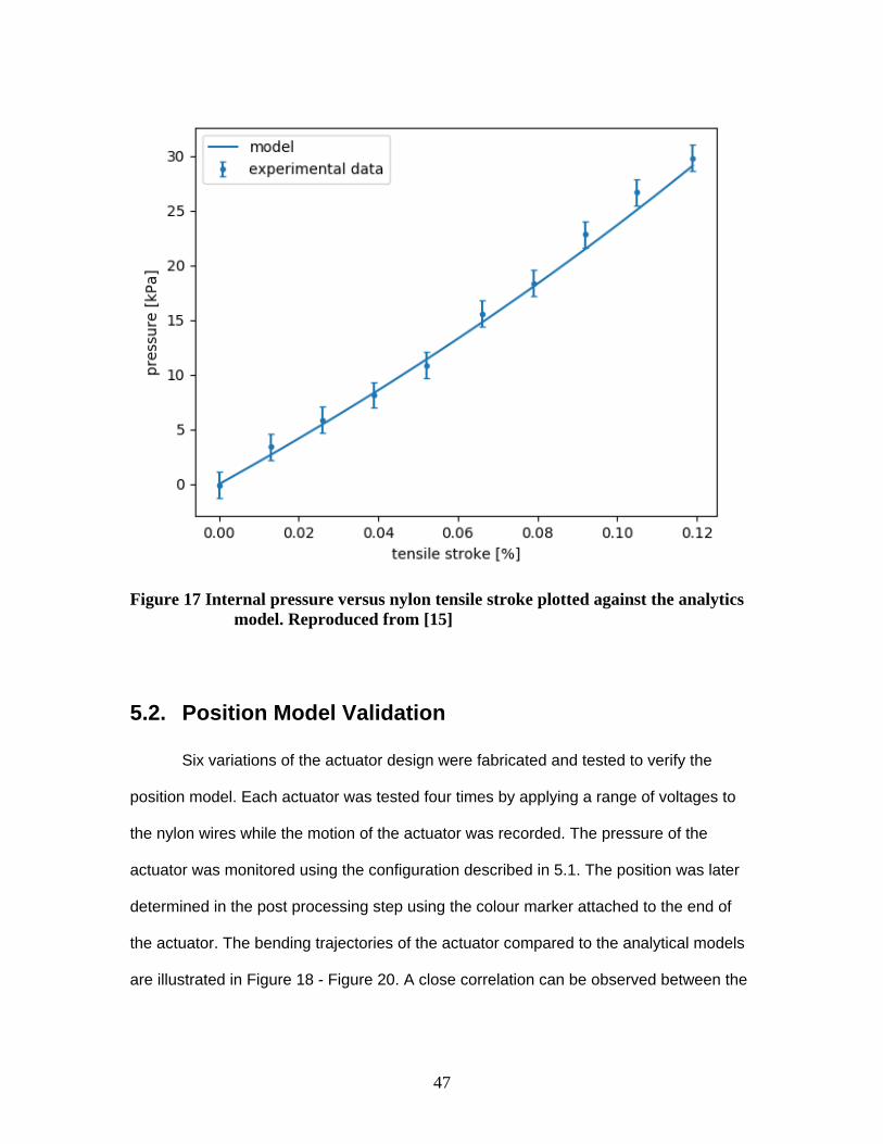
47
Figure 17 Internal pressure versus nylon tensile stroke plotted against the analytics model. Reproduced from [15]
5.2. Position Model Validation
Six variations of the actuator design were fabricated and tested to verify the
position model. Each actuator was tested four times by applying a range of voltages to
the nylon wires while the motion of the actuator was recorded. The pressure of the
actuator was monitored using the configuration described in 5.1. The position was later
determined in the post processing step using the colour marker attached to the end of
the actuator. The bending trajectories of the actuator compared to the analytical models
are illustrated in Figure 18 - Figure 20. A close correlation can be observed between the

48
theoretical model and the experimental data. A maximum displacement error of 4.2%
was calculated demonstrating the validity of the models.
Small discrepancies can be seen in the pressure values due to initial prebending
and gravitational influences. This resulted in a pressure error of 8.3%.
Figure 18 Actuator analytical model visualized against a bending actuator. Reproduced from [15]

49
Figure 19 Bending angle versus pressure, for radius values ranging from 6.0 to 14.0mm. Reproduced from [15]

50
Figure 20. Bending angle versus pressure, for wall thickness ranging from 1.0 to 4.0mm. Reproduced from [15]

51
5.3. Force Model Validation
To verify the force model, experimental results were obtained by examining six
variations of the actuator design. A range of voltages was applied to the nylon actuators
and the force was measured at the actuator tip as shown in Figure 21. The top layer of
the actuator was fixed to prevent the actuator from bending during pressurization.
Figure 21 Actuator force measured with the top layer constrained
The forces at the tip of the actuator compared to the analytical models are shown
in Error! Reference source not found. – Figure 23. The experimental results show a
close correlation with the predicted force at the tip of the actuator for this configuration. A
maximum displacement error of 5.3% was calculated demonstrating the validity of the
models. Small discrepancies can be seen in the pressure values due to initial
prebending and gravitational influences.

52
Figure 22 Force measurements of the actuator versus internal pressure for various radii. Reproduced from [15]

53
Figure 23 Force measurements of the actuator versus internal pressure for various actuator lengths. Reproduced from [15]

54
Figure 24 Actuator forces versus internal pressure for various actuator wall thicknesses. Reproduced from [15]
5.4. Position Controller
Using the analytical model developed above, a position controller was developed
to demonstrate the simplicity at which the proposed actuator may be controlled. A
feedback control loop with an angle filter, as shown in Figure 26, was implemented to
demonstrate the ability of the analytical model of Equation 13 to use pressure
information to estimate bending angle in real time. Although the input to the system is
voltage, the variation in the size of the actuator, and the ambient temperature affects the
heating and cooling rate of the nylon. As a result, voltage provides an unreliable input to
the feedback controller. Alternatively, the internal air pressure is relatively simple to

55
measure in real time and is a good predictor of the actuator bending angle as shown in
Figure 20. In addition, utilizing pressure as the input to the feedback control loop, makes
the controller more versatile as it can be used in more operating environments. To
control the power input to the nylon, a simple bang bang controller was utilized due to
the slow cooling rate of the actuator. The pressure for the actuator was monitored using
the configuration described in section 5.1. The power input to each actuator was
modulated using a RFP30N06LE MOSFET connected to an Arduino Mega (Figure 25).
Figure 25 Schematic of control system for each actuator. Each actuator was equipped with a pressure sensor and the power was modulated to the nylon using a RFP30N06LE MOSFET.

56
The feedback control loop was tested against a sinusoidal reference angle and a
step response reference angle. The controller was successful in tracking an angle signal
of 0.04 Hz as shown in Figure 27 and Figure 28. The maximum applied power to the
actuator was 1.92W (12V, 160mA). A larger power input could also be used which would
reduce the actuator heating times, however, the cooling time is limited by the natural
convection.
Figure 26 Schematic of the closed loop controller for actuator bending angle. Reproduced from [15]

57
Figure 27 Feedback control loop performance. Actuator tracking a sinusoidal reference angle with a period of 0.04Hz. Reproduced from [15]

58
Figure 28 Feedback control loop performance. Step response of the actuator controller. Reproduced from [15]
5.5. Soft Gripper Demonstration
In order to provide evidence of the potential ability of the soft actuator to be used
in robotic applications, a prototype of a soft robotic gripper (Figure 30) was constructed.
Three actuators were mounted in a holding structure fabricated in ABS via a 3D printer.
The power input to each actuator was modulated using a RFP30N06LE MOSFET as
shown in Figure 25 connected to an Arduino Mega (Figure 29).The pressure for each
actuator was also monitored and connected to an arduino similar to the configuration
described in 5.1.
The gripper was powered by a single 9V battery and with each actuator drawing
approximately 130mA of current. Figure 31 shows the pressure in the actuators during

59
the grasping motion. Figure 30 shows the gripper grasping a ping pong ball through all
stages of grapsing. Figure 31 shows that the gripper was able to grasp various objects.
Each actuator could be manipulated individually, and there was no noticeable crosstalk
between actuators caused by convective heating. Since the gripper is made out of a soft
polymer and the actuation system is soft there is potential for this system to grasp
delicate objects as similar configurations have demonstrated this capability [139] [140]
[141] [142] [143].
Figure 29 Top down view of the internals of the gripper demonstration. Each actautor is equipped with a pressure sensor which is connected to an arduino mega. The power to each actuator is modulated using a RFP30N06LE MOSFET controlled by the arduino.

60
Figure 30 Soft gripper demonstration. The soft gripper shown grasping a ping pong ball through all stages of grasping. Reproduced from [15]

61
Figure 31 The soft gripper shown grasping various objects.

62
Figure 32 Plot of pressure versus time for the actuators in the gripper

63
Chapter 6. Design Considerations
This chapter uses the analytical models developed in chapter 4 to outline a set of
design considerations for the proposed actuator. The presented materials are here in
combination with the material from chapter 5 are aimed towards fulfillment of the fourth
objective of the thesis; characterize the performance of the proposed fluidic actuator.
The entirety of the chapter is an excerpt from section 3 and section 4 of the article
published in L. Sutton and C. Menon “Design of a soft fluidic actuator using nylon
artificial muscles,” Engineering Research Express Accepted June 2019.
The proposed fluidic actuator may be suitable for applications where pressure
driven actuators are currently used. However, the size and forces generated by the
actuator are limited by the capabilities of the nylon artificial muscles. It is important for
the robotics designer to understand how these limitations affect the actuator’s
capabilities. Using the models developed above, a set of theoretical limits could be
calculated based on the physical dimensions of the actuator to establish the maximum
achievable torques and maximum actuator dimensions for a full range of motion.
6.1. Nylon Limitations
According to Equation 7, the stress in the nylon is proportional to the forces
generated by the internal pressure and material stresses in the actuator walls.
Furthermore, the nylon tensile stroke is a function of the temperature only and is
independent of the tensile stress as long as the tensile stress remains below the ultimate
tensile strength of the nylon [133]. Using the tensile stroke, the internal pressure in the
actuator can be calculated using Equation 8 and the material stresses in the actuator
can be calculated using Equation 13. Based on the calculated pressure and material
stresses, the stress in the nylon can be calculated using Equation 8. It is assumed that

64
this force is evenly distributed over the number of nylon coils which can be calculated
based on the wrapping angle (Figure 33) and the width of the nylon. The force in the
nylon is then checked to remain below the ultimate tensile strength. Furthermore, Haines
et al showed that the nylon ultimate tensile strength and the tensile stroke is dependent
on the nylon coil index and that an inverse relationship exists between the nylon ultimate
tensile strength and the maximum tensile stroke. The results are summarized in Figures
Figure 34 -
Figure 36.
Figure 33 Depiction of the nylon wrapping angle
Figure 34 shows how the actuator dimensions affect the tensile force generated
in the nylon. As the actuator dimensions increase, the force required to compress the
actuator walls increases beyond the maximum capabilities of the nylon. The nylon
limitations for various coil indices are shown with a dashed black line.

65
Figure 34 Forces in the nylon versus. tensile stroke for various actuator dimensions
6.2. Maximum Achievable Torque
Using the results of Figure 34, the maximum achievable torque for a proposed
actuator can be calculated given the actuator dimensions and the nylon coil index
(Equation 14). The nylon thresholds for various wrapping angles were determined using
Equation 8 and are shown as a dashed black line. From Figure 35 it can be observed
that a larger coil index produces a larger torque for smaller actuator dimensions.
However, as the actuator dimensions increase, the nylon quickly reaches its limitations.
In addition, by increasing the wrapping angle, the expansion force generated by the
internal pressure and materials stresses is distributed over less nylon coils. As a result,
the maximum force in the nylon is reached sooner for actuators of the same dimensions.

66
Figure 35 Maximum achievable torques for versus actuator dimensions. Actuator limitations shown as a dashed black line
Range of motion
Figure 36 summarizes the theoretical limits for the bending angle of the proposed
actuator. The bending angle was calculated using Equation 13 and Equation 8 was used
to determine the bending angle limitations. Given an actuator and its dimensions, using
Figure 36 the designer can determine if the actuator can undergo a full range of
motion. As the actuator dimensions increase, the stress in the nylon increases causing
the range of motion to decrease. Similar to the maximum torque, by increasing the
wrapping angle, the expansion force generated by the internal pressure and materials
stresses is distributed over less nylon coils. As a result, the maximum force in the nylon
is reached sooner for actuators of the same dimensions.

67
Figure 36 Maximum achievable range of motion versus actuator dimensions. Actuator limitations shown as a black dashed line.
Using the results of Figures Figure 34 -
Figure 36, a robotics designer with higher force requirements might consider using the
maximum radius 20mm with a nylon coil index of 1.1 (Figure 35).The designer could
select a large but reasonable wall thickness of 6mm and a length of 90mm. According to
Figure 35, this actuator could produce a maximum force of 1.2N. The resulting actuator
could also undergo a full range of motion according to
Figure 36.On the contrary, another robotics application may have smaller force
requirements but the actuator is space constraint. An actuator with a radius of 7.5mm,

68
length of 70mm and a wall thickness of 2mm can produce a maximum force of 0.15N if
nylon with a coil index of 1.7 is used.

69
Chapter 7. Discussion
The entirety of the chapter is an excerpt from section 5 of the article published in
L. Sutton and C. Menon Design of a soft fluidic actuator using nylon artificial muscles,”
Engineering Research Express Accepted June 2019.
Soft fluidic actuators can generate complex motions at a low mechanical cost. To
date, the development of such actuators has largely relied on mechanical compressors
or pumps to supply the input fluid pressure. The proposed actuator aims to bridge the
gap between current fluidic actuators and a complete, compact, soft solution. By utilizing
nylon actuators, the proposed fluidic actuator has no need for an external compressor or
pump while still providing the benefits of a soft, compliant fluid actuator.
Depending on the application, the proposed actuators could be used with off the
shelf batteries or commercially available flexible batteries to produce a completely soft
portable system. For example, the gripper described above in Figure 31 used a 9V
battery and drew approximately 400mA of current at maximum capacity. Flexible
batteries such as those avaible from Jenax Inc. [144] could have been used for limitted
amounts of time. In contrast, conventional bending fluidic actuators require both a
compressor and an electrical system. Although the electrical system can be made
portable or flexible, soft portable compressors are not currently available [4]. For the
robotics designer looking for portable soft robotics system, the proposed actuators could
potentially be suitable.
For robotics designers looking to utilize the proposed actuators, analytical
models were developed to provide performance information on the actuator prior to
manufacturing. The position model showed a close correlation with the experimental
data. A maximum displacement error of 4.2% was calculated demonstrating the

70
accuracy of the models. The small discrepancies were likely due to the initial bending of
the actuator caused by gravitational influences. Additionally, the force model showed
good correlation with the experimental results (maximum force error of 4.3%). Using the
analytical models, a minimalist position controller was implemented to demonstrate how
a designer might implement a control system in practice. The analytical models were
also used to calculate a set of design considerations for the robotics engineer. These
design plots can be used select the optimal nylon fibre and actuator dimensions to best
suit the designer’s requirements.
Nylon actuators offer a lightweight alternative solution to traditional actuation
methods. Currently the system is limited by restricted muscle relaxation time. Thus,
further research could be conducted to improve the speed of cooling the nylon. This
could be done by immersing the coils in water, increasing air flow around the wire,
adding heat sinks to the design, or decreasing the air temperature around the coils.
Additionally, this problem could be overcome by adding opposing actuators that could
compensate for the slow relaxation times. The wrapping procedure could also be
improved. Currently the nylon is wrapped radially by hand as this was a preliminary
research project. However, the procedure could be improved by creating an automated
system. The system could rotate the silicone bladder while moving along the axis. The
coiled nylon could be fed and wrapped around the bladder as it rotates. This could
improve the reliability of the proposed actuators by reducing the bulging effect and
potential twisting induced caused by wrapping the actuators manually.
Research in the area of soft robotics is an emerging field and nylon actuators
could potentially provide a soft, lightweight, alternative to pressure driven fluidic
actuators. By combining the nylon actuators with flexible power sources future studies

71
may examine how robots can be composed of entirely soft components and remain
completely self-contained.

72
Chapter 8. Future Work
A flexible fluidic actuator is presented which utilizes nylon artificial muscles for
activation. The proposed actuator is made up of two main components, a soft fluid
bladder, and artificial muscles embedded and or wrapped around the fluid bladder. The
shape of the fluid bladder and the arrangement of the artificial muscles allow the
actuator to deform to the desired configuration. By utilizing contractile elements, the
actuator does not require a pump or compressor for actuation. Various embodiments of
the actuator are proposed which may produce motions including but not limited to
elongation, bending, twisting, and planar motion. The proposed fluidic actuator may be
suitable for a number of applications including but not limited to surgical robots,
wearable orthoses, or robotic grippers. This chapter outlines potential future directions
for further development of the proposed actuator and potential applications where it may
make an immediate impact.
8.1. Potential Applications
As described in Chapter 2, soft robotics is entering many new fields and new
applications are being actively studied. The proposed actuator can potentially be used in
a number of applications where soft these robotic actuators are currently. However, as
outlined in Chapter 6. Design Considerations, the proposed actuator is most suitable for
applications with certain force requirements and size constraints. Based on the results of
Chapter 6, the proposed actuator has the potential to make the most immediate impact
on assistive wearable devices, and locomotion robots.
The proposed actuator could be used in the design of an assistive wearable
orthosis for the hand and wrist. These devices have a range of force requirements
dependent on the severity of the affected extremity. Assistive devices to for the hand
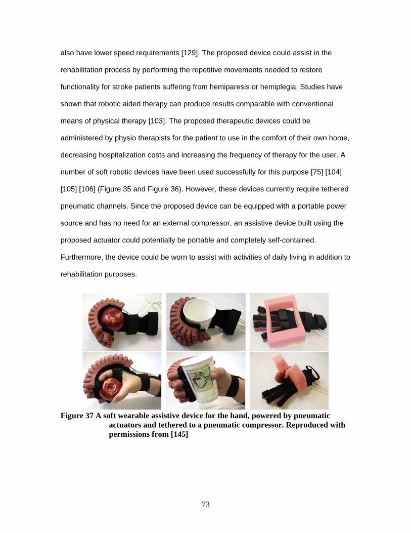
73
also have lower speed requirements [129]. The proposed device could assist in the
rehabilitation process by performing the repetitive movements needed to restore
functionality for stroke patients suffering from hemiparesis or hemiplegia. Studies have
shown that robotic aided therapy can produce results comparable with conventional
means of physical therapy [103]. The proposed therapeutic devices could be
administered by physio therapists for the patient to use in the comfort of their own home,
decreasing hospitalization costs and increasing the frequency of therapy for the user. A
number of soft robotic devices have been used successfully for this purpose [75] [104]
[105] [106] (Figure 35 and Figure 36). However, these devices currently require tethered
pneumatic channels. Since the proposed device can be equipped with a portable power
source and has no need for an external compressor, an assistive device built using the
proposed actuator could potentially be portable and completely self-contained.
Furthermore, the device could be worn to assist with activities of daily living in addition to
rehabilitation purposes.
Figure 37 A soft wearable assistive device for the hand, powered by pneumatic
actuators and tethered to a pneumatic compressor. Reproduced with permissions from [145]

74
Figure 38 (a) A soft robotic rehabilitation device for the hand. (b) A patient utilizing the device under superision of the clinician. The pump and control box required to activate the device are also depicted. Reproduced with permissions from [107]
In addition to wearable devices, the proposed actuator could potentially find use
in the development of locomotive robots. As outlined in Chapter 2, soft bodied robots
have enabled a number of locomotive robots. The soft locomotive robots have shown
improved navigation capabilities over their rigid counterparts when exploring new
terrains; examples include vertical surfaces, desert sand, rubble, and deformable
surfaces such as mud and soil [76]. This could allow soft robots to be used in new
operating environments for many exciting applications including, search and rescue, or

75
environmental monitoring. However, many of the studied soft robotic systems require
power and control signals delivered through pneumatic tethers since compressors are
relatively heavy [24] (Figure 39 Figure 40). Furthermore, these robots typically have
small force requirements and limited speed requirements depending on the application.
The proposed actuator could potentially be used in place of these pneumatic actuators
to create a completely soft, self-contained portable system.
Figure 39 A soft robotic system used to sample deep coral reefs. The robot is currently limited by its tethers to its pneumatic power source. Reproduced with permissions from [146]

76
Figure 40 A soft robotic system used to mimic snake like locomotion for environmental monitoring purposes. The robot is currently limited by its bulky rigid pneumatic compressor. Reproduced with permissions from [147]
8.2. Actuator Development
The proposed actuator incorporates a flexible fluid bladder wrapped embedded
with nylon artificial muscles. The developed actuator is configured to bend the actuator
when the nylon is activated. However, the fluid bladder can take any shape, it is only
dictated by the mold in which it is cast. This in combination with a unique configuration of
nylon wrapped and embedded in the bladder can be used to deform the actuator to the
desired shape. A variety of configurations are proposed to achieve, the following motions
elongation, contraction, bending, twisting, and planar movement. Future development of
the proposed actuator could explore the following actuator designs.
Figure 41 shows the arrangement of a fluidic actuator where elongation is
achieved. This is achieved by wrapping the soft fluid bladder in artificial muscles. When
the artificial muscles activate, the fluid bladder is compressed in the radial direction. As a
result, the fluid pressure increases and acts to expand the soft bladder. The bladder is

77
constrained in the radial direction due to the stiffness artificial muscles. However, there
is no constraint in the axial direction which allows the soft bladder to expand in the axial
direction.
Figure 41 Perspective views of the fluidic actuator which uses artificial muscles to increase the internal pressure, elongating the actuator.
Figure 42 shows a configuration of the actuator where twisting is achieved. This may be
achieved by wrapping the artificial muscles around the soft bladder in a spiral pattern.

78
The contraction of the muscles causes the fluid pressure to increase while also acting to
provide torsion on the soft bladder around the central axis.
Figure 42 Perspective views of the fluidic actuator with artificial muscles arranged to twist the actuator around the central axis.
Figure 43 shows a configuration of the flexible fluidic actuator where a
combination of bending and twisting is achieved. This configuration uses the same
fundamental principles described for Figure 13 to achieve bending. However, the radial
muscles are arranged in an asymmetric spiral pattern around the fluid bladder. In
addition, an asymmetric backbone is added to actuator to further increase twisting.

79
Figure 43 Illustration of a bending fluidic actuator with actuators arranged to bend and twist the actuator.
Figure 44 shows a further embodiment of the configuration proposed in Figure 43
where a combination of bending and twisting is achieved. This configuration uses the
same fundamental principles described for Figure 43 to achieve bending and twisting.
However, the axial muscles are activated individually to achieve twisting in both
directions. The proposed configuration may be useful for not only grasping but also for
manipulating the object after it has been grasped.

80
Figure 44 Illustration of a bending fluidic actuator with actuators arranged to bend and twist the actuator in both directions by activating each set of axial nylon wires individually. The activated nylon is shown in red and the resulting bending configuration is shown above.
Figure 45 Shows a further embodiment of the flexible fluidic actuator for
achieving planar motion. By combining three bending fluidic actuators in parallel, planar
motion may be achieved by activating the actuators in conjunction. This allows for the
individual pressurization of the fluidic channels and allows for selective bending in the x-

81
y plane of the actuator, as well as motion in the z-direction perpendicular to the plane of
the actuator.
Figure 45 Illustration of a bending fluidic actuator with actuators arranged to allow for planar movement.
Figure 46 Illustrates a further embodiment of the flexible fluidic actuator for
achieving planar motion. Three bending fluidic actuators, are combined in parallel similar
to the configuration described in Figure 45. However, the actuators’ cross section is
designed such that the combination of the three forms a circular cross section.

82
Figure 46 Illustration of a bending fluidic actuator with actuators 3 actuators arranged in a compact cylinder to allow for planar movement.
Figure 47 Illustrates a further embodiment of the flexible fluidic actuator for
achieving planar motion. In this case, only a single cylindrical fluid bladder is required
while three axial nylon wires are arranged in parallel to control the direction of bending.

83
Figure 47 Illustration of a bending fluidic actuator with one fluidic actuator and 3 axial nylon wires arranged in parallel to allow for planar movement.
Figure 48 Illustrates a further embodiment of the flexible fluidic actuator for
achieving planar motion. Two bending fluidic, are combined in parallel similar to the
configuration described in Figure 46. However, the actuators’ cross section is designed

84
such that bending is increased in one direction. The proposed actuator may be useful for
grasping and manipulating objects as it can bend in the direction of the object and twist
after the object has been grasped.
Figure 48 Illustration of a bending fluidic actuator with actuators 2 actuators arranged in a compact cylinder to allow for planar movement.

85
Chapter 9. Conclusion
The purpose of this thesis was to address the following objectives:
1. Explore the feasibility of developing a soft bending fluidic actuator which
makes use of nylon artificial muscles eliminating the need for an external
compressor or pump
2. Utilize established hyper elastic models to investigate the quasi-static
behaviour of the proposed fluidic actuator
3. Verify the proposed model
4. Characterize the performance of the proposed fluidic actuator
The previous chapters address the thesis objectives as follows.
Chapter 3 focuses on objective 1; Explore the feasibility of developing a soft
bending fluidic actuator which makes use of nylon artificial muscles eliminating the need
for an external compressor or pump. By utilizing nylon actuators, the proposed fluidic
actuator has no need for an external compressor or pump while still providing the
benefits of a soft, compliant fluid actuator.
Chapter 4 focuses on objective 2; Utilize established hyper elastic models to
investigate the quasi-static behaviour of the proposed fluidic actuator. The thermo-
mechanical model for silver coated nylon actuators was characterized in previous
research [17] [133]. This model was used to calculate the squeezing capacity of the
nylon actuators. The actuator bodies were fabricated using Silicone TC-5005 from BJB
Enterprises, which exhibits non-linear behavior during large mechanical deformations.
Previous studies have shown that an incompressible Ogden model can accurately
predict the deformation behavior of Silicone TC-5005 [20]. Combining the Ogden model

86
for silicone with the force and displacement model for nylon actuators, a quasi-static
model was developed for the proposed fluidic actuator.
Chapter 5 focuses on objective 3; verify the proposed model and partially
addresses objective 4; characterize the performance of the proposed fluidic actuator.
The position model showed a close correlation with the experimental data. A maximum
displacement error of 4.2% was calculated demonstrating the accuracy of the models.
The small discrepancies were likely due to the initial bending of the actuator caused by
gravitational influences. Additionally, the force model showed good correlation with the
experimental results (maximum force error of 4.3%). Using the analytical models, a
minimalist position controller was implemented to demonstrate how a designer might
implement a control system in practice.
Chapter 5 addresses objective 4; Characterize the performance of the proposed
fluidic actuator. The analytical models were used to calculate a set of design
considerations for the robotics engineer. The design plots outline the range of
dimensions, and force requirements where the proposed actuator is most suitable.
Furthermore, the design plots can be used select the optimal nylon fibre and actuator
dimensions to best suit the designer’s requirements. Typically, the designer will select an
actuator based on either the force requirements or the size constraints. For example, the
designer can calculate the maximum forces achievable given a set of actuator
dimensions. Alternatively, they can calculate the forces achievable given a set of
actuator dimensions. Additional optimizations can also be made based on the nylon
selected nylon coil index.

87
Bibliography
[1] M. T. Tolley et al. "A Resilient, Untethered Soft Robot," Soft Robotics, vol. 1, no.
3, pp. 213-223, 2014.
[2] C. Bicchi, et al. "Safety for physical human–robot interaction," in Springer
handbook of robotics, Springer, 2008, pp. 1335-1348.
[3] Polygerinos P, et al. "Soft robotics: Review of fluid‐driven intrinsically soft
devices; manufacturing, sensing, control, and applications in human‐robot
interaction," Advanced Engineering Materials, 2017.
[4] D. Rus and M. T. Tolley, "Design, fabrication and control of soft robots," Nature,
vol. 521, pp. 467-475, 2015.
[5] J. D. Madden et al. "Artificial muscle technology: physical principles and naval
prospects," IEEE Journal of Oceanic Engineering, vol. 29, no. 3, pp. 706-728,
2004.
[6] M. Wehner and et al., "Pneumatic Energy Sources for Autonomous and
Wearable Soft Robotics," Soft Robotics, vol. 1, no. 4, pp. 263-274, 2014.
[7] C. G. Burgar and et al., "Development of robots for rehabilitation therapy: the
Palo Alto VA/Stanford experience," Journal of rehabilitation research and
development, vol. 37, no. 6, pp. 663--674, 2000.
[8] Y. Bar-Cohen, "Electroactive Polymers as Artificial Muscles: Capabilities,
Potentials and Challenges," in Robotics 2000, Albuquerque, New Mexico, 2000.

88
[9] M. Fremond, “Shape Memory Alloy: A Thermomechanical Macroscopic Theory”,
Vienna: Springer Vienna, 1996.
[10] H. Moein and C. Menon, "An active compression bandage based on shape
memory alloys: a preliminary investigation," Biomedical engineering online, vol.
13, no. 1, p. 135, 2014.
[11] W. Huang, "On the selection of shape memory alloys for actuators," Materials
and Design, vol. 23, no. 1, pp. 11-19, 2002.
[12] M. Yip and N. Gunter, "High-Performance Robotic Muscles from Conductive
Nylon Sewing Thread," in 2015 IEEE International Conference on Robotics and
Automation, Seattle, Washington, 2015.
[13] K. Otsuka and C. M. Wayman, Shape Memory Materials, London: Cambridge
University Press, 1999.
[14] C. Haines and et al., "Artificial Muscles from Fishing Line and Sewing Thread,"
Science, vol. 343, no. 6173, pp. 868-872, February 2014.
[15] L. Sutton and C. Menon, "A Soft Fluidic Actuator based on Nylon Artificial
Muscles," Smart Materials and Structures, 2019.
[16] R. Kaur et. al. “Review of soft robotic grippers,” Robotica, Submitted for
publication January 2019
[17] L. Sutton, H. Moein, A. Rafiee, J. D. Madden and C. Menon, "Design of an
assistive wrist orthosis using conductive nylon actuators," in Biomedical
Robotics and Biomechatronics (BioRob), Singapore, 2016.

89
[18] C. D. &. R. D. Onal, "Autonomous undulatory serpentine locomotion utilizing
body dynamics of a fluidic soft robot," Bioinsipred Biomimetics, vol. 8, no. 26,
2013.
[19] L. Mazzolai, et al. "Soft-robotic arm inspired by the octopus," Bioinspiration &
Biomimetics, vol. 7, 2015.
[20] A. Marchese, et al. "Autonomous soft robotic fish capable of escape maneuvers
using fluidic elastomer actuators". Soft Robotics, vol. 1, 2014
[21] A. H., The Significance of Early Bronze Age Iron Objects from Kaman-
Kalehöyük,, Turkey, 2008.
[22] C. M. Abidi H, "On intrinsic safety of soft robots," Fronteirs in Robotics, vol. 4,
no. 5, 2017.
[23] Trivedi D, et al. "Soft robotics: Biological inspiration, state of the art, and future
research," Applied bionics and biomechanics, vol. 5, no. 3, pp. 99-117, 2008.
[24] D. Rus and M. Tolley, "Design, fabrication and control of soft robots," Nature,
vol. 521, no. 7553, pp. 467-475, 2015.
[25] B. Chang, J. Berring, M. Venkataram and C. Menon, "Bending fluidic actuator for
smart structures," Smart Materials and Structures, vol. 20, no. 3, p. 8, 2011.
[26] F. Daerden and D. Lefeber, "Pneumatic artificial muscles: actuators for robotics
and automation," European journal of Mechanical and Environmental
Engineering, vol. 47, pp. 10-21, 2000.
90
[27] B. Tondu, V. Boitier and P. Lopez, "Naturally compliant robot‐arms actuated by
McKibben artificial muscles," in Proceedings of ‘94 IEEE‐SMC Conference, San
Antonio, TX, 1994.
[28] C.-P. Chou and B. Hannaford, "Measurement and modeling of McKibben
pneumatic artificial muscles," IEEE Transactions on Robotics and Automation ,
vol. 12, no. 1, pp. 90-102, 1996.
[29] G. Klute, J. Czerniecki and B. Hannaford, "McKibben artificial muscles:
pneumatic actuators with biomechanical intelligence," in 1999 IEEE/ASME
International Conference on Advanced Intelligent Mechatronics, Atlanta, GA,
USA, 1999.
[30] M. Sugisaka and H. Zhao, "The characteristics of McKibben muscle based on
the pneumatic experiment system," Artificial Life and Robotics, vol. 11, no. 2, pp.
223-226, 2007.
[31] Z. Zhang and M. Philen, "Pressurized artificial muscles," Journal of Intelligent
Material Systems and Structures , vol. 23, no. 3, pp. 255-268, 2011.
[32] W. Liu and C. R. Rahn, "Fiber-Reinforced Membrane Models of McKibben
Actuators," Journal of Applied Mechanics, vol. 70, no. 6, pp. 853-859, 2003.
[33] S. Kurumaya, H. Nabae, G. Endo and K. Suzumori, "Design of thin McKibben
muscle and multifilament structure," Sensors and Actuators A: Physical, vol.
261, pp. 66-74, 2017.

91
[34] Carabin G, et al, “Experimental Evaluation and Comparison of Low-Cost
Adaptive Mechatronic Grippers”. International Conference on Robotics in Alpe-
Adria Danube Region 2017 Jun 21, pp. 630-637 Springer, Cham.
[35] B. Mosadegh, et al., "Pneumatic networks for soft robotics that actuate rapidly,"
Advanced Functional Materials, vol. 24, no. 15, pp. 2163-2170, 2014.
[36] F. Ilievski, A. D. Mazzeo, R. F. Shepherd, X. Chen and G. M. Whitesides, "Soft
Robotics for Chemists," ANGEWANDTE CHEMIE INTERNATIONAL EDITION,
vol. 50, no. 8, pp. 1890-1895, 2011.
[37] R. F. Shepherd, et al., "Soft Machines That are Resistant to Puncture and That
Self Seal," Advanced Materials, vol. 25, no. 46, pp. 6709-6713, 2013.
[38] A. A. Stokes, et al., "A Hybrid Combining Hard and Soft Robots," Soft Robotics,
vol. 1, no. 1, pp. 70-74, 2014.
[39] B. S. Homberg, R. K. Katzschmann, M. R. Dogar and D. Rus, "Haptic
Identification of Objects using a Modular Soft Robotic Gripper," in 2015
IEEE/RSJ International Conference on Intelligent Robots and Systems (IROS),
Hamburg, Germany, 2015.
[40] A. Meller, et al. " Reconsidering the McKibben muscle: energetics, operating
fluid, and bladder material.," Journal of Intelligent Material Systems and
Structures, vol. 18, pp. 2276-2293, 2014.
[41] Suzumori K, et al. "A bending pneumatic rubber actuator realizing soft-bodied
manta swimming robot.," in 2007 IEEE International Conference on Robotics
and Automation, 2007.

92
[42] R, Shepherd, et al., "Multigait soft robot," in Proceedings of the national
academy of sciences, 2011.
[43] B.C MacMurray, et al., "Poroelastic foams for simple fabrication of complex soft
robots," Advanced Materials, vol. 41, pp. 6334-6340, 2015.
[44] G. McCarthy, D. Effraimidis, B. Jennings, N. Corso, C. D. Onal and M. Popovic,
"Hydraulically actuated muscle (HAM) exo-musculature," in Robot Makers: The
Future of Digital Rapid Design and Fabrication of Robots, California, CA, 2014.
[45] P. Polygerinos, Z. Wang, K. C. Galloway, R. J. Wood and C. J. Walsh, "Soft
Robotic Glove for Combined Assistance and at-Home Rehabilitation," Robotics
and Autonomous Systems, vol. 73, pp. 135-143, 2015.
[46] K. C. Galloway, K. P. Becker, B. Phillips, J. Kirby, S. Licht, D. Tchernov, R. J.
Wood and D. F. Gruber, "Soft Robotic Grippers for Biological Sampling on Deep
Reefs," Soft Robotics, vol. 3, no. 1, pp. 23-33, 2016.
[47] D. Trivedi, D. Dienno and C. D. Rahn, "Optimal, Model-Based Design of Soft
Robotic Manipulators," Journal of Mechanical Design, vol. 130, no. 9, 2008.
[48] A. Yamaguchi, K. Takemura, S. Yokota and K. Edamura, "A robot hand using
electro-conjugate fluid," Sensors and Actuators A: Physical, vol. 170, no. 1-2, pp.
139-146, 2011.
[49] C. D. Onal and D. Rus, "A Modular Approach to Soft Robots," in The Fourth
IEEE RAS/EMBS International Conference on Biomedical Robotics and
Biomechatronics, Roma, Italy, 2012.

93
[50] B. Mazzolai and V. Mattoli, "Robotics: Generation soft," Nature, vol. 536, pp.
400-401, 2016.
[51] R.F Shepherd, et al., "Using explosions to power a soft robot," in Angewandte
Chemie International Edition, 2013.
[52] K. J. Kim and S. Tadokoro, Electroactive Polymers for Robotic Applications:
Artificial Muscles and Sensors, Springer Publishing Company, Incorporated,
2007.
[53] C. Laschi, M. Cianchetti, B. Mazzolai, L. Margheri, M. Follador and P. Dario,
"Soft Robot Arm Inspired by the Octopus," Advanced Robotics, vol. 26, no. 7,
pp. 709-727, 2012.
[54] S. Kim, E. Hawkes, K. Choy, M. Joldaz, J. Foleyz and R. Wood, "Micro artificial
muscle fiber using NiTi spring for soft robotics," in 2009 IEEE/RSJ International
Conference on Intelligent Robots and Systems, St. Louis, USA, 2009.
[55] H.-I. Kim, M.-W. Han, W. Wang, S.-H. Song, H. Rodrigue and S.-H. Ahn,
"Design and Development of Bio-mimetic Soft Robotic Hand with Shape Memory
Alloy," in 2015 IEEE International Conference on Robotics and Biomimetics
(ROBIO), Zhuhai, China, 2015.
[56] A. Villanueva, C. Smith and S. Priya, "A biomimetic robotic jellyfish (Robojelly)
actuated by shape memory alloy composite actuators," Bioinspiration &
Biomimetics, vol. 6, no. 3, 2011.

94
[57] N. Shinjo and G. Swain, "Use of a shape memory alloy for the design of an
oscillatory propulsion system," IEEE Journal of Oceanic Engineering, vol. 29, no.
3, pp. 750-755, 2004.
[58] G.-Y. Gu, J. Zhu, L.-M. Zhu and X. Zhu, "A survey on dielectric elastomer
actuators for soft robots," Bioinspiration & Biomimetics, vol. 12, no. 1, 2017.
[59] R. Pelrine, R. Kornbluh, J. Joseph, R. Heydt, Q. Pei and S. Chiba, "High-field
deformation of elastomeric dielectrics for actuators," Materials Science and
Engineering C, vol. 11, pp. 89-100, 2000.
[60] M. Wissler and E. Mazza, "Modeling and simulation of dielectric elastomer
actuators," Smart Materials and Structures, vol. 14, no. 6, pp. 1396-1402, 2005.
[61] L. Patrick, K. Gabor and M. Silvain, "Characterization of dielectric elastomer
actuators based on a hyperelastic film model," Sensors and Actuators A, vol.
135, no. 2, pp. 748-757, 2007.
[62] Y. Liu, L. L. Z. Zhang and J. Leng, "Dielectric elastomer film actuators:
characterization, experiment and analysis," Smart Materials and Structures, vol.
18, no. 9, p. 10 pages, 2009.
[63] G. Kofod and W. Wirges, "Energy minimization for self-organized structure
formation and actuation," Applied Physics Letters, vol. 90, no. 8, 2007.
[64] O. A. Araromi, I. Gavrilovich, J. Shintake, S. Rosset, M. Richard, V. Gass and H.
R. Shea, "Rollable Multisegment Dielectric Elastomer Minimum Energy
Structures for a Deployable Microsatellite Gripper," IEEE/ASME Transactions on
Mechatronics, vol. 20, no. 1, pp. 438-446, February 2015.

95
[65] J. Shintake, S. Rosset, B. Schubert, D. Floreano and H. Shea, "Versatile Soft
Grippers with Intrinsic Electroadhesion Based on Multifunctional Polymer
Actuators," Advanced Materials, vol. 28, no. 2, pp. 231-238, January 2016.
[66] G.-K. Lau, K.-R. Heng, A. S. Ahmed and M. Shrestha, "Dielectric elastomer
fingers for versatile grasping and nimble pinching," Applied Physics Letters, vol.
110, no. 8, 2017.
[67] K. Takagi, M. Yamamura, Z.-w. Luo, M. Onishi, S. Hirano, K. Asaka and Y.
Hayakawa, "Development of a Rajiform Swimming Robot using Ionic Polymer
Artificial Muscles," in 2006 IEEE/RSJ International Conference on Intelligent
Robots and Systems, Beijing, China, 2006.
[68] S. Guo, Y. Ge, L. Li and S. Liu, "Underwater Swimming Micro Robot Using IPMC
Actuator," in 2006 IEEE International Conference on Mechatronics and
Automation, Luoyang, China, 2006.
[69] S.-W. Yeom and I.-K. Oh, "A biomimetic jellyfish robot based on ionic polymer
metal composite actuators," Smart Materials and Structures, vol. 18, no. 8, p. 10
pages, 2009.
[70] B. Bhandari, G.-Y. Lee and S.-H. Ahn, "A review on IPMC material as actuators
and sensors: Fabrications, characteristics and applications," International
Journal of Precision Engineering and Manufacturing, vol. 13, no. 1, pp. 141-163,
2012.
[71] G. Runge, S. Zellmer, T. Preller, G. Garnweitner and A. Raatz, "Actuation
Principles for the Bioinspired Soft Robotic Manipulator SpineMan," in 2015 IEEE

96
International Conference on Robotics and Biomimetics (ROBIO), Zhuhai, China,
2015.
[72] M. C. Carrozza, G. Cappiello, G. Stellin, F. Zaccone, F. Vecchi, S. Micera and P.
Dario, "A Cosmetic Prosthetic Hand with Tendon Driven Under-Actuated
Mechanism and Compliant Joints: Ongoing Research and Preliminary Results,"
in 2005 IEEE International Conference on Robotics and Automation, Barcelona,
Spain, 2005.
[73] M. Manti, T. Hassan, G. Passetti, N. D'Elia, C. Laschi and M. Cianchetti, "A
Bioinspired Soft Robotic Gripper for Adaptable and Effective Grasping," Soft
Robotics, vol. 2, no. 3, pp. 107-116, 2015.
[74] M. Manti, T. Hassan, G. Passetti, N. d’Elia, M. Cianchetti and C. Laschi, "An
Under-Actuated and Adaptable Soft Robotic Gripper," in Living Machines 2015:
Biomimetic and Biohybrid Systems, Barcelona, Spain, 2015.
[75] G. Rateni, M. Cianchetti, G. Ciuti, A. Menciassi and C. Laschi, "Design and
development of a soft robotic gripper for manipulation in minimally invasive
surgery: a proof of concept," Meccanica, vol. 50, no. 11, pp. 2855-2863, 2015.
[76] M. Calisti, A. Arienti, F. Renda, G. Levy, B. Hochner, B. Mazzolai, P. Dario and
C. Laschi, "Design and development of a soft robot with crawling and grasping
capabilities," in 2012 IEEE International Conference on Robotics and
Automation, Saint Paul, MN, 2012.
[77] M. E. Giannaccini, I. Georgilas, I. Horsfield, B. H. P. M. Peiris, A. Lenz, T. Pipe
and S. Dogramadzi, "A variable compliance, soft gripper," Autonomous Robots,
vol. 36, no. 1-2, pp. 93-107, 2014.

97
[78] A. Asbeck, R. Dyer, A. Larusson and C. Walsh, "Biologically-inspired soft
exosuit," in 2013 IEEE International Conference on Rehabilitation Robotics
(ICORR), Seattle, WA, 2013.
[79] I. Hyunki, B. K. Brian, S. MinKi and C. Kyu-Jin, "Exo-Glove: A Wearable Robot
for the Hand with a Soft Tendon Routing System," IEEE Robotics & Automation
Magazine, vol. 22, no. 1, pp. 97 - 105, 2015.
[80] R. Cieślak and A. Morecki, "Elephant trunk type elastic manipulator - a tool for
bulk and liquid materials transportation," Robotica, vol. 17, no. 1, pp. 11-16,
1999.
[81] M. W. Hannan and I. D. Walker, "Kinematics and the Implementation of an
Elephant's Trunk Manipulator and Other Continuum Style Robots," Journal of
Field Robotics, vol. 20, no. 2, pp. 45-63, 2003.
[82] F. Renda, M. Giorelli, M. Calisti, M. Cianchetti and C. Laschi, "Dynamic Model of
a Multibending Soft Robot Arm Driven by Cables," IEEE Transactions on
Robotics, vol. 30, no. 5, pp. 1109-1122, 2014.
[83] F. Maghooa, A. Stilli, Y. Noh, K. Althoefer and A. H. Wurdemann, "Tendon and
pressure actuation for a bio-inspired manipulator based on an antagonistic
principle," in 2015 IEEE International Conference on Robotics and Automation
(ICRA), Seattle, WA, 2015.
[84] V. Vikas, P. Grover and B. Trimmer, "Model-free control framework for multi-limb
soft robots," in 2015 IEEE/RSJ International Conference on Intelligent Robots
and Systems (IROS), Hamburg, Germany, 2016.
98
[85] F. Erzincanli and J. Sharp, "Meeting the need for robotic handling of food
products," Food Control, vol. 8, no. 4, pp. 185-190, 1997.
[86] P. Chu, T. Ilschner and D. Caldwell, "Robotic manipulation of food products – a
review," Industrial Robot: An International Journal, vol. 30, no. 4, pp. 345-354,
2003.
[87] S. Davis, J. Gray and D. G. Caldwell, "An end effector based on the Bernoulli
principle for handling," Robotics and Computer-Integrated Manufacturing, vol.
24, no. 2, p. 249–257, 2008.
[88] A. Pettersson, T. Ohlsson, S. Davis, J. Gray and T. Dodd, "A hygienically
designed force gripper for flexible handling of variable and easily damaged
natural food products," Innovative Food Science and Emerging Technologies,
vol. 12, no. 3, pp. 344-351, 2011.
[89] M. Monta, N. Kondo and K. Ting, "End-Effectors for Tomato Harvesting Robot,"
Artificial Intelligence Review, vol. 12, no. 1-3, p. 11–25, 1998.
[90] K. Tanigakia, T. Fujiuraa, A. Akase and J. Imagawa, "Cherry-harvesting robot,"
Computers and Electronics in Agriculture, vol. 63, no. 1, pp. 65-72, 2008.
[91] S. Hayashi, K. Shigematsu, S. Yamamoto, K. Kobayashi, Y. Kohno, J. Kamata
and M. Kurita, "Evaluation of a strawberry-harvesting robot in a field test,"
Biosystems Engineering, vol. 105, no. 2, pp. 160-171, 2010.
[92] Y.-C. Chiu, S. Chen and J.-F. Lin, "Study of an Autonomous Fruit Picking Robot
System in Greenhouses," Engineering in Agriculture, Environment and Food,
vol. 6, no. 3, pp. 92-98, 2013.

99
[93] R. Bogue, "Flexible and soft robotic grippers: the key to new markets?,"
Industrial Robot: An International Journal, vol. 43, no. 3, pp. 258-263, 2016.
[94] "Soft Robotics Inc.," [Online]. Available: https://www.softroboticsinc.com/.
[Accessed 22 July 2017].
[95] Grabit. [Online]. Available: https://grabitinc.com/products/. [Accessed 22 July
2017].
[96] K. Malachowski, J. Breger, H. R. Kwag, M. O. Wang, J. P. Fisher, F. M. Selaru
and D. H. Gracias, "Stimuli-Responsive Theragrippers for Chemomechanical
Controlled Release," Angew Chem Int Ed, vol. 53, no. 31, pp. 8045-8049, 2014.
[97] J. Burgner-Kahrs, D. C. Rucker and H. Choset, "Continuum Robots for Medical
Applications: A Survey," IEEE Transactions on Robotics, vol. 31, no. 6, pp.
1261-1280, 2015.
[98] G. o. Canada, "Heart Disease in Canada," 9 February 2017. [Online]. Available:
https://www.canada.ca/en/public-health/services/publications/diseases-
conditions/heart-disease-canada.html. [Accessed 20 June 2019].
[99] E. T. Roche, et al., "A bioinspired soft actuated material," Advanced Materials,
vol. 8, pp. 1200-1206, 2014.
[100] V. Torregrossa, et al., "Results with SynCardia total artificial heart beyond 1
year.," Asaio Journal, vol. 6, pp. 626-634, 2014.
[101] BERKELEY, "New light-controlled gel makes big strides in soft robotics,"
Berekeley News, [Online]. Available: http://news.berkeley.edu/2013/05/28/light-
controlled-hydrogel/. [Accessed 22 July 2017].

100
[102] J. C. Breger, C. Yoon, R. Xiao, H. R. Kwag, M. O. Wang, J. P. Fisher, T. D.
Nguyen and D. H. Gracias, "Self-Folding Thermo-Magnetically Responsive Soft
Microgrippers," Applied Materials & Interfaces, vol. 7, no. 5, pp. 3398-3405,
2015.
[103] Z. Xiao, et al., "Towards the Development of a Portable Wrist Exoskeleton," in
International Conference on Robotics and Biomimetics, 2011, Phuket, Thailand.
[104] P. Maciejasz, "A survey on robotic devices for upper limb rehabilitation," Journal
of neuroengineering and rehabilitation, vol. 11, no. 1, pp. 1-29, 2014.
[105] C. G. Burgar, "Development of robots for rehabilitation therapy: the Palo Alto
VA/Stanford experience," Journal of rehabilitation research and development,
vol. 37, no. 6, pp. 663-674, 2000.
[106] P. S. Lum, "Robot-assisted movement training compared with conventional
therapy techniques for the rehabilitation of upper-limb motor function after
stroke," Archives of physical medicine and rehabilitation,, vol. 83, no. 7, pp. 952-
959, 2002.
[107] P. Polygerinos and e. al., "Towards a Soft Pneumatic Glove for Hand
Rehabilitation," in IEEE/RSJ Int. Conf. Intell. Robot. Syst, Japan, 2013.
[108] C. Bartlett, et al., "A soft robotic orthosis for wrist rehabilitation," Journal of
Medical Devices, vol. 9, 2015.
[109] M. Sasaki, et al. "Development of active support splint driven by pneumatic soft
actuator," in 2005 IEEE international conference on robotics and automation,
2005.

101
[110] C. Wehner, et al., "A lightweight soft exosuit for gait assistance," in IEEE
international conference on robotics and automation, 2013.
[111] R. Park, "A soft wearable robotic device for active knee motions using flat
pneumatic artificial muscles," in 2014 IEEE International Conference on
Robotics and Automation, 2014.
[112] H. Lin, "Softrobots in space: a perspective forsoft robotics".
[113] D. Katzschmann, "Hydraulic autonomous soft robotic fish for 3D swimming.," in
Internation Symposium on Experimental robotics, 2014.
[114] A. D. Marchese, R. K. Katzschmann and D. Rus, "Whole arm planning for a soft
and highly compliant 2D robotic manipulator," in 2014 IEEE/RSJ International
Conference on Intelligent Robots and Systems, Chicago, IL, 2014.
[115] Pneubotics, "Lightweight Manipulators for Cost Effective Corrosion Inspection,"
[Online]. Available:
https://static1.squarespace.com/static/54c29f04e4b08c8849fa740e/t/583f15294
6c3c47182ea4e9a/1480529194064/Pneubotics-
Cost+Effective+Corrosion+Inspection.pdf. [Accessed 24 July 2017].
[116] D. C, "Control of elastic soft robots based on real-time finite element method," in
IEEE International Conference on Robotics and Automation, 2013.
[117] D. Marchese, "Dynamics and trajectory optimization for a soft spatial fluidic
elastomer manipulator.," J. Robotics Res, vol. 35, no. 8, pp. 1000-1019, 2016.
[118] M. Hines, "Inflated soft actuators with reversible stable deformations," Advanced
Materials, 2016.

102
[119] L. Cecilia and C. Matteo, "Soft Robotics: New Perspectives for Robot Bodyware
and Control," Frontiers in Bioengineering and Biotechnology , vol. 2, p. 3, 2014.
[120] C. N. Farrow N, "A soft pneumatic actuator that can sense grasp and touch," in
IEEE/RSJ International Conference on Intelligent Robots and Systems (IROS),
2015.
[121] I. rivedi "Soft robotics: Biological inspiration, state of the art, and future
research," Applied bionics and biomechanics, 2008.
[122] R. Bilodeau RA, "Monolithic fabrication of sensors and actuators in a soft robotic
gripper," in International Conference on Intelligent Robots and Systems (IROS),
2015.
[123] R. Case JC, "Sensor enabled closed-loop bending control of soft beams," Smart
Materials and Structures, 2014.
[124] C. Iida F, "Soft robotics: challenges and perspectives," Procedia Computer
Science, 2011.
[125] J. Turkseven, "Observer based impedance control of a pneumatic system with
long transmission lines," in 2016 IEEE International Conference on Robotics and
Automation, 2016.
[126] Zhao H, "A helping hand: Soft orthosis with integrated optical strain sensors and
EMG control," in EEE Robotics & Automation , 2016.
[127] C. Skorina, "Motion control of a soft-actuated modular manipulator," in 2016
IEEE International Conference on Robotics and Automation, 2016.

103
[128] R. Shepherd, "Using explosions to powera soft robot," Angewandte Chemie, vol.
125, 2013.
[129] P. Polygerinos, Z. Wang, J. T. Overvelde, K. C. Galloway, R. J. Wood, K.
Bertoldi and C. J. Walsh, "Modeling of soft fiber-reinforced bending actuators,"
Modeling of soft fiber-reinforced bending actuators, vol. 31, no. 3, pp. 778-789,
2016.
[130] B. Chang and et al., "A spatial bending fluidic actuator: fabrication and quasi-
static characteristics," Smart Materials and Structures, vol. 21, no. 4, 2012.
[131] S. Mirvakili, A. Rafie, I. Hunter, C. S. Haines, N. Li, J. Foroughi, S. Naficy,
Spinks, B. Geoffrey M and J. D. Madden, "Simple and strong: Twisted silver
painted nylon artificial muscle actuated by Joule heating," International Society
for Optics and Photonics, 2014, vol. 9056, p. 9056I, 2014.
[132] B. Chang, "Quasi-static analysis and control of planer and spatial bending fluidic
actuator," Simon Fraser University, Burnaby, British Columbia, Canada, 2011.
[133] R. Kianzad, F. Ko, G. M. Spinks and J. D. Madden, "Nylon coil actuator
operating temperature range and stiffness," in PIE Smart Structures and
Materials+ Nondestructive Evaluation and Health Monitoring, 2015.
[134] S. Sharafi and G. Li, "A multiscale approach for modeling actuation response of
polymeric artificial muscles," Soft matter, vol. 11, no. 19, pp. 3833-3843, 2015.
[135] S. Ahmadi and e. al., "Fabrication and electromechanical examination of a
spherical dielectric elastomer actuator," SMART MATERIALS AND
STRUCTURES, vol. 22, no. 22, p. 115004, 2013.

104
[136] E. Potter, Gender and Boyle's law of gases, Indiana University Press, 2001.
[137] S. Kianzad and et al., "Nylon coil actuator operating temperature range and
stiffness," in SPIE Smart Structures and Materials+ Nondestructive Evaluation
and Health Monitoring, 2015.
[138] S. Pourazadi, S. Ahmadi and C. Menon, "On the design of a DEA-based device
to potentially assist lower leg disorders: an analytical and FEM investigation
accounting for nonlinearities of the leg and device deformations," Biomedical
Engineering online, vol. 14, no. 1, p. 103, 2015.
[139] M. Manti, "A novel type of compliant underactuated robotic hand for grasping,"
Soft Robotics, vol. 2, no. 3, 2015.
[140] Soft Robotics Inc., [Online]. Available: https://www.softroboticsinc.com.
[Accessed 11 January 2019].
[141] Y. Wei, "A Novel Variable Stiffness Robotic Gripper Base on Integrated Soft
Actuatoring and Particle Jamming," Soft Robotics, vol. 3, no. 3, pp. 134-143,
2016.
[142] R. D. a. O. Brock, "A novel type of compliant underactuated robotic hand for
dexterous grasping," Internal Journal of Robotics Research, vol. 35, no. 1-3, pp.
107-116, 2016.
[143] Z. W. a. S. Hirai, "A 3D printed soft gripper integrated with a curvature sensor for
studying soft grasping," in IEEE Internation Symposium on System Integration,
2016.

105
[144] Jenax Incorporated, "Jenax Battery Products," Jenax Incorporated, [Online].
Available: https://jenaxinc.com/. [Accessed 23 January 2019].